AlR COND/TIONING SYSTEMS-HEATING AND COOLING LOADS … · R-values, square footage, and design...
23
SYSTEMS-HEATING AND COOLING LOADS AlR COND/TIONING Key Words: heat Sains heat lag heat leakage heat loads Learning Oblectives; After studying thischapter, you will be able to: a Define heat load and identify its sources for both heat- ing and cooling of space. a Determine heat loadsthrough the use of tl- or R-values, square footage, and design temperature charts, a Practic€ approved safety procedures. heattransfer coeff icient heattransief rate pondedroof R value thermal conductivity U value Heating and cooling systems rcquire that the urlit be sized {or the specific application. Th€ heating system should be capable of ke€pint ihe occupied sPace warm even on the coldest winter days {or the Siven location. In much of the United States,typical heating conditions arc as follows: 70'F (2'1"C) inside temperature and 0'F ( 18'C) outside tempeHture with a 15 mph wind blow- ing. The air conditioning system must also be sized to provide adequate cooling capacity for the wamest days 27.1 Heat Loads Heat always flows ftom hot to cold. In the winier, a conditioned space must be heated with mough heat enerBy Gtus) to compensate for the heat loss to the colder outside ambient air. For heatint purposes, it is de- sirable to reduce lenf loss. During the sulllrner, enough heai must be removed from the conditioned sPace to cool it as heat €nters from the walm outside air In sum- mer conditions, ii is desirable to minimize ftert 8rir. In both conditions, it is necessaryto reduce the transfei of heat from inside th€ conditioned space to the outdoors or to prevent heat transfer from the outdoors into ihe condihonedspace. Buildings should be desitned to reduce heat trans- Ier This is refered to as making the buildint enveloPe 'tiqht." However, rccent studies have sholt'n that mak- inta building too "tight" may result in insuflicient air changes within the building. In hrm, ihis may lead to sick btilding syndrofie. To prevent this, it is important to brins in some fresh ouiside air and to maintain continu_ ous air changes within a building. Th€ amount of heat transfer from a building is detemined by the buildinS's desisn, consfuction mate als, and location. Jhe maximum heat load (loss or Sain) is deterrrined ror d peood of one hour Charls {for]nd in numeroLrs manuals) arc used to make the comPutation. Heat load calculation manuals are available through various sources. The Air Conditioning Conhactors of Anerica (ACCA) publish t}].e Laad Cnlculatian fot R?side11 tial Wintet andSummer Ail Conditioius,known as Manual J. They also publish lodd Calculation for CannerciLl Suln merand winter Ail Condit,otr'trq, known as Manual N. 1033
Transcript of AlR COND/TIONING SYSTEMS-HEATING AND COOLING LOADS … · R-values, square footage, and design...
SYSTEMS-HEATINGAND COOLINGLOADS
AlR COND/TIONING
Key Words:
heat Sainsheat lagheat leakageheat loads
Learning Oblectives;After studying this chapter, you will be able to:
a Define heat load and identify its sources for both heat-ing and cooling of space.
a Determine heat loads through the use of tl- orR-values, square footage, and design temperaturecharts,
a Practic€ approved safety procedures.
heat transfer coeff icientheat transief rateponded roofR valuethermal conduct iv i tyU value
Heating and cooling systems rcquire that the urlitbe sized {or the specific application. Th€ heating systemshould be capable of ke€pint ihe occupied sPace warmeven on the coldest winter days {or the Siven location.In much of the United States, typical heating conditionsarc as follows: 70'F (2'1"C) inside temperature and 0'F( 18'C) outside tempeHture with a 15 mph wind blow-ing. The air conditioning system must also be sized toprovide adequate cooling capacity for the wamest days
27.1 Heat Loads
Heat always flows ftom hot to cold. In the winier,a conditioned space must be heated with mough heatenerBy Gtus) to compensate for the heat loss to thecolder outside ambient air. For heatint purposes, it is de-sirable to reduce lenf loss. During the sulllrner, enoughheai must be removed from the conditioned sPace tocool it as heat €nters from the walm outside air In sum-mer conditions, ii is desirable to minimize ftert 8rir. Inboth conditions, it is necessary to reduce the transfei ofheat from inside th€ conditioned space to the outdoorsor to prevent heat transfer from the outdoors into ihecondihoned space.
Buildings should be desitned to reduce heat trans-Ier This is refered to as making the buildint enveloPe'tiqht." However, rccent studies have sholt'n that mak-inta building too "tight" may result in insuflicient airchanges within the building. In hrm, ihis may lead tosick btilding syndrofie. To prevent this, it is important tobrins in some fresh ouiside air and to maintain continu_ous air changes within a building. Th€ amount of heattransfer from a building is detemined by the buildinS'sdesisn, consfuction mate als, and location.
Jhe maximum heat load (loss or Sain) is deterrrinedror d peood of one hour Charls {for]nd in numeroLrsmanuals) arc used to make the comPutation.
Heat load calculation manuals are available throughvarious sources. The Air Conditioning Conhactors ofAnerica (ACCA) publish t}].e Laad Cnlculatian fot R?side11tial Wintet and Summer Ail Conditio ius, known as Manual
J. They also publish lodd Calculation for CannerciLl Sulnmer and winter Ail Condit,otr'trq, known as Manual N.
1033

1034 Modern Refr geration and Air Conditioning
There are several major heat loads:. Heat that is transmitted through walls, ceilings, and
floors (conduction).. Heat necessary to conhol moisfure content in the air.. Conditioning the air that enters the building by
leakage and for veniilation.. The sun produces heat in buildings, directly
through thewindows.It also produces heat by heat-ing the surfaces it stfikes (a cooling load).
. Energy devices-light fixtures, electric motors, elec-tric or gas stoves, etc.-all produce heat. People,too, release a considerable amount of heat,In a[ cases, the heat load ca be descdbed as ei-
ther sensible heat load (temperature change) or laientheaL load lmoi. lure) evapo.al ing o' corden5ing.
27.1.1 Heat Loads for HeatingHeai loads for heating include all means by which
heat will be losi Ircm a building. They also include heailoss due to warming oI cooier substances brcughi iniothe building, Figure 27-1. The major heat losses are:
. Conduction ihrough walls, ceilings, and floors.
. Air leaking out of ihe bu dtug (exfiltration), andthat which leaks into the building (infiltration).
. Combustion air leavinS ihe flue from gas or oil fur-naces, or ftorn firePlaces.Normally, all other heai losses are i8nored. They are
too small, relatively, to affect the size of the unit to beinstalled.
27.1 .2 Heat Loads {or CoolingThere are delinite sources of heat gain in \4.arm
weather includint heat and air leakage irlto the build-ing, \'entilation air, sun load, heat ftom appliances andlighis, and heat gain from occupants.
Heal gain rcfers to the heat added to a space that isbeing cooled. This heat must be removed to keep tem-perature and rclative humidity at the values des ed.
Heaf gain in wann weather is pioduced by heatconduction. This takes place through the walls, ceilings,floors, windows, and doors of the enclosure. Also, heatenters d1e room by way of infiltrated air People and ani-mals in the room also give off heai.
Miscellaneous sources of heai are electrical devices(lights and motors), gas-burning devices, and steamtables. Another source of heat is the srn. The sun maybe a considerable source oI heat. See Figue 27-2.
Heat LeakageHeat leaknge is the heat that is conducted through
the walls, ceilings, and noors. The total heat leaka8e iscomputed as follows: First, detemine the arca of eachtype of surface through which heat js leaking. Next fhdthe U-value for each type of surface. The Ll-?atre repre-sents the amouni oI heat that will pass from one side ofa wa1l to the other. Total heat leakage is found by multiplyin8 the heat leakage areas by their respectiveU-values. The U-value may also be refefied to as theheat tl'Lnsfer coefficient,
Heat leakage can also be computed usin8 the fter-mal resistance of the struciure, Thermal resistance isknown as the R-i'al e. lt is the reciprocal of conductance(C) or ihe overall heat transfer (U).
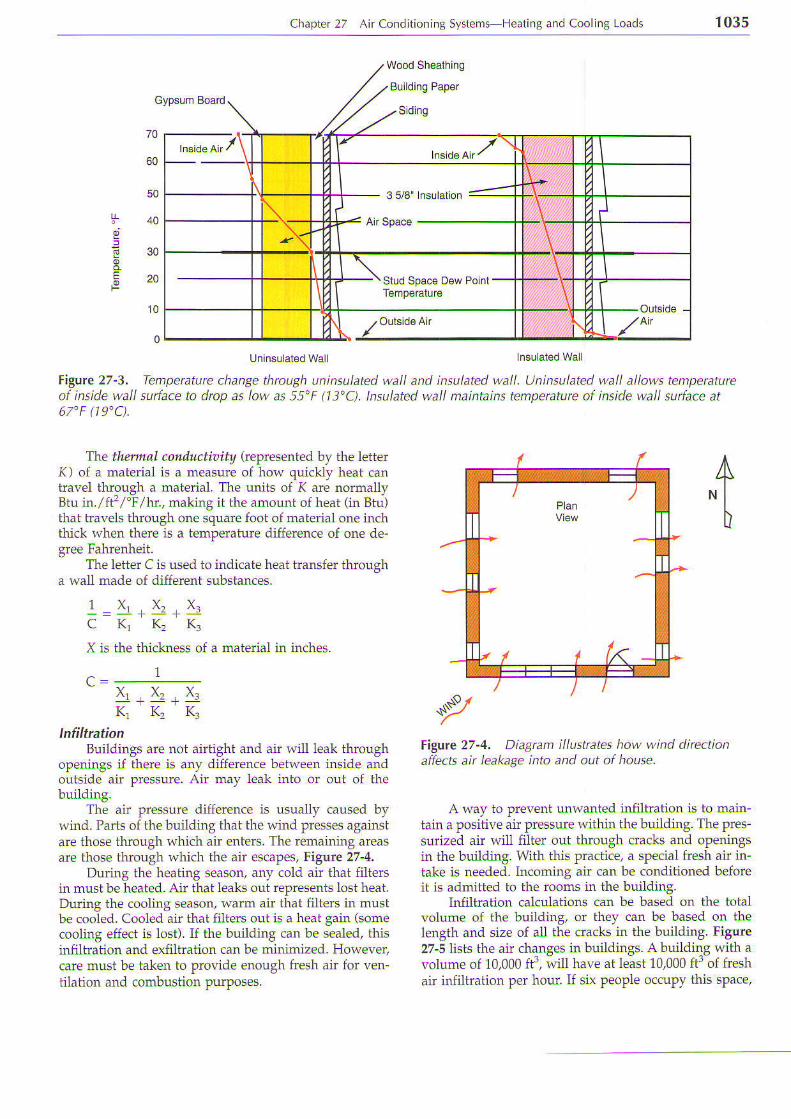
Building materials have been iested to deteminethe amount of heat they will transfer Figure 27-3 showstemperature chan8es during the heating season for ai}?ical wood sided wall. Both noninsulated and insu-lated walls are shown-
Dl
: ( 18 !C )
70.F (21.1 'C)
Figure 27-1. Large heat losses occur durin| heatingselson due to cold air filteting into building and warnair filterinE out. Heat is also lost through walls, floors,winclows, and ceilinSs.
Fi1l|ne 27-2. Heat is gained in building durina coolinqseison. Note heat leaka]e, ai infiltration, sun load,lights, appliances, and moisturc sources. [email protected]. K-Kitchen LR Living roan.W-Washer. D Drier
" |{ ' . / / ' r r : :
Chapier 27 Air Cond rioning Systems Heating and Cool ng Loads r035
The thennal cotlductioity (represented by the letter() of a material is a measure of how quickly heat cantrd\el throuBh d md'endl The uni l - of r dre nornauyB r u i n . f i ' ' t h r . m a l . n g i r l h e a m o u n t o f h e d t , i n B l u 'that travels through one square foot of maiedal one inchthick when there is a temperature difference of one de-gree Fahrenheit.
The letter C is used to indicate heai transfer througha wall made of different substances.
K, K, K?
Building Paper
4
Figwe 27"4, Dia7ran illustrates how wind dircctionaffects air leakaqe into and out of house.
A way to pre\.ert unwanted infiltration is to main-tain a positive air pressure rvithin the buildinS. The pres-sudzed air will filter out through cracks and openingsin ihe building. With this practice, a special fresh air in-take is needed. Incorning air can be condiiioned beforeii is admitied to the rooms in the buildint.
Infiltration calculations can be based on the totalvolume of ihe building, or they can be based on thelength and size oI all the cracks in the buildhg. Figure27-5 lists the air chanqes in buildinqs. A buildins with avolume oI 10,000 ft3, ;i have af least 10,000 ftr;f freshair infiltration per hour. If six people occuPy this sPace,
Sdlng
Figwe 27-3. Temperature chanle thrau1h uninsulated wall and insulated wall. Uninsulated wall allows tempetatureof inside wall surface ta drop as lovr as 55"F (13"C). lnsulated wall naintains temperature ol inside wall surface at67'F (19'C).
5tEP
I
-
X is the thickness of a matedal in inches.
X. X" X.KT K' K3
InfiltrationBuildings are not airtight and air will ieak through
openings if there is any difference bet$'een insid€ andoutside air pressure- Air may leak into or out of thebuilding.
The air pressure difference is usually caused bywind. Parts of the building that the wiid presses againstare those thro(gh vrhich air enters. The remaining areasare those through which the air escapes, Figure 27-4.
During the heating season, any cold air that filteGin must be heated. Air that leaks out represents lost heai.During the cooling season, warm air that filters in mustbe cooled. Cooled air that filters out is a heai gain (somecooling effect is lost). If the building can be sealed, thisinfiltration and exfiltration can be mlnimized. However,care must be taken to Provide enough fresh air for ven-lilaiion and combustion purposes.

1036 Modern Refr gerat ion and A r Condi t ion ing
1 Side Expossd
3 Sides Expos€d
Enirances
11 1 1 2222-j
l isde Flm (Resistance = 0.68)
Figure 27-5. Appraximate number af air chan1esdesirable per haur for various raom exposurcs.
ihere is 10,000 - 6 or 1657 ft3 per ho11| for each person,or 1667 - 60 = 27.8 cfm (0.79 m'lmin.). The air changervill be reduced considerably if ihis buildint is constructed with vapor barriers. Fiiting a1l doors and windows with weather-stripping will also rcduce the airchange. Ii may even be rcduced to the Pojni of Dnsafevertilation. (There will be ioo little oxygen in the air)
Heat Transfer RateT]ne heat transfer nte is the amount of heat con-
ducted through a structure for a given unit of time. It isusualll'represented blr ihe letter Q and expressed inBiu/hr. The iotal heat transfer rate is found as follorvs:The l'\eat transfer coefficieni (U-\'alue) is multiplied bythe temperature diflerence and the alea
Heai Transfer Raie = Heat tnnsfer coefficient xarea X temPerair.rre difference
Q = (U x Area) x (To TJWhere: To = Outside temPerahrte
Tr = Inside temPeralrire
U-value fot Computing Heat LeakageIn cornputing heat transfer, the letter U has ahnost
rle sarne vaiue as the leiter C. The value of U, however,includes ihe additional insulating effect of an air filmThis air iilm always exists on each side of the surfaceS€e Figure 27-6.
It I = ---
1 * x , * X ' * X ' * 1F, K, K, K. F.
F i ) , \ e h L . r l r " 1 . r e r l l , r ' , u t h i h e i r r , d F I - t m Fis the heat transfer ihrouth the outside air film U-valueis a term indicatirlg the arnount of heat transferredthrougll a structure ('all):
U = Btu/ftrl'F/hour
U-r'alues are based on a 15 mPh t'ind on the outsideand a 15 fpm (1/5 mPh) drait on the inside lvall sur
The U-r'alue for ost tyPes of construction canbe obtained ftonl reference books P biished bv the
American Society of HeatinS, Retuigeratiig and Air-
Conditioning Engineers (ASHR{E) Figure 27-7 is a
condensed table fol some of the more common construc-
tions.
i - - Ol ls ide Fim (Festsra.ce = o. r7)
25132' Fir Sheathing, BLri d ng Paper,and Yellow-Pine Lap Siding
(Resslance= 1.85)
l\,linera Fiber B!tl lnsulalon 3,5(Fes stance = 13)
Figure 27-6. Dnwin7 of external wall section showsinaide and oLttside air iilm. C values are rcciprccal ai theR-value ol material, or C = 1/R. (Edison Electric lnstitute)
Civen the U-value, ihe desiSn temperature condr-tions of 70'F (21"C) indoors and 0'F ( 18'C) outdoors,and the area, calculate the heat load as follows:
Formula:Heat flo(, = area X
temPeraiure difference x U-valueToial heat transfer (Q) = U x
total sldace x temperaiure diffefence
Example:A structure has 400 fts of surface The temPeraiure
difference is 70'F The structure has a brick veneer walland no insulation. lt has a U-value of 0.25
Solution:This U value means that 025 Btu will iransler
through each square fooi of wall {or each one degree Ftemperature difference in one hour'
Total heai transfer (Q) = 400 x (70"F 0'F) x 0.25= 4 0 0 x 7 0 x 0 2 5: 28,000 x 0.25= 7000 Btu/hr.
Example:Ii btal surface area is 1200 ft2, heat transfer can be
determined as iollows:
Q = 1200 x (70"F 0'F) x 0.25= 1200 x 70 x 0.25: 84,000 x 0.25= 21,000 Btu/hr.
The same method of comPuting heat ieakage isused when using the metdc system. Only the uniis used
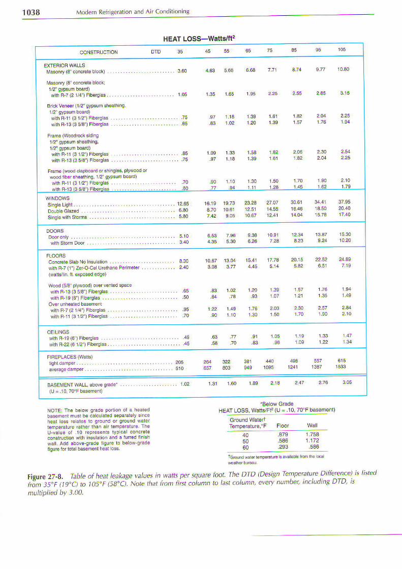
are changed.Fisire 27-a shows t,vpical heat leakage listed in
'lvatts ;er square foot. To obtain the waii load per de-gree F;divide the "35 column" bv 35. To convert watts
io Biri/hr., ml tipll' r'atts by 3.414358.

Chapter 27 Air Conditioning Systems Heating and Coollng Loads 1037
Heat LoadsConstants for Heat Transmission (U and R Values)
E&r essed r Blu per I our oe' sqLa.s lool per deg.ee -€mpe.a_'rrc d 'l€r€lce, bas€d 04 1 5 np1 w nd vebcity.
Gene€l Wall C @rrrcadon3
&ckVonsor 1' !ryood Siding StudsG y p s u m B o a d l / 2 . . . . . . .
Bigld nsulalion, SIuds, GypsumB @ r d 1 / 2 . . . . . . . .
&ckveneer I Wood Siding, Sludsl' Polystyrene Insu alionGypsum Board 1/2
Bdckven€€r 1 Wood Siding. Sluds.Rock woor Fin, Larh and P 4ter
3.71
13.5
1 / 2 W a L b o a r d . . . . .
1 Poystyreie,l/2 Wallboad
3.51
wood S d ng on 1'Wood Shaalh ^0,Studs Gypsum Boad l,2' . . . . ..
woodSdng,Slrealhing. Sluds. GypsumBoad 12 ,l Polyslyrene . . . .
Wood Sd ng, Shealhing, Sluds.
G y p s u m B o a d 1 / 2 . . . . .
Wood Sd ng, Sh€alhinq, SIudB, Rockwoo l F l l La t l i and P as ter . . .
Nor6: FEm6 Walrs wlth Sh ngle ExteiofF n sh same as wa s wi$ \ryood sidinq
Stuc6, Wood S d nA, Studs. GypsumB o a d . . . . .
Stuoco on 2t32 Rig d Insulalion.Sluds 1/2 Rigid Insuauonand Pla6ler. . .
Stucco on 1/2 Rigd Insualion
Lath and Prdler . ..
U
.15
.472
Nol6: In gen6r6l ior coo ngcomptnal ons, bas€ ih6 ca cu al onstor heat gain from adjoiningnon{ond t oned rmms on a d fi€renlial€qual lo 1D rh6 d llerenrial
GypsunBoadlz on Bolh S des.Gypsum Boa'd 1/2 on Bolh S des,
Foam nsulal on .
u
.23
3 . i3
1 .23
214
4 Thrck co^cele, No Fini6h
4 Concrcre Suspenden Pra5lsce hg
4 Concrct€,lvlela L6rh and PlasrerCeiling Hadwood FLoor onPinosub-Fmdng . . . . . . .
4 Concrct€, Hadwoon and P n€ FLoof,No Ce nq 323
Hadwood and Pino F oodng
a n d P a s t e r C e i l i n g . . .
Rough Pine Floor. wood Lalhand P 4 l€ r c€ i l ng . . .
No Foor Lalh and P aslr Coilinq
3 5 / 3 ' B o c k W o o F i l . . . . .
1 ' F € x b e I n s u l a l i o n . . .
S h € a l h i n q . . . . . . .
AphatShinges,l Flexible
kphal Shingl$, Polysly€no 1
S i n g a G a $ . . . . . . .
Singlo Glass and Slom Wlndow
Doub€ G ass, Inlemediale AirS p a c o l / 2 ' . . . . . . . . .
€ x 6 ' t 4 B l o c k s . . .
1.73
Figure 27-7. lJ- and R-values arc Eiven fot walls, ceilings, floors, and partitions for various types of construction andfot various thicknesses. (Reprinted by permission of the American Society of HeatinS, ReftiSerating, andAi-Conditioning Engineers, Atlanta, Ceorgia)
1038 Modern RefriEeration and Air Condltionins
HEAT Loss-Watt€i/ft'?
DTD 35 45 55 65 75 35
Masonry (3' conc€l€ block)
Maonry {3 coicele blocki
s l lh F-7 (21 l4 ' ) F ibeEa6 . . . .
Bick v6neer (1/2' gypsum shea$ng
with R-11(31/2') Fib€rg as ..w lh Br3{35 /3 ) F ibercLas . . . .
wlth F-11(31/2') Fib€rc aswlhBl3 (3 5/3 ) F boQlas .
.€5
1.95
1.24 1.39 1.57.97 1 .13
.90 1 . r0
1 .53 i .32
1,501.24
2.06i .32
Frame (wood capboad orshlnglos, pywood orwood iib€rsh€alhing, 1/2 gypsum boad)with R'11(31/2') Fib€rg as ..
12 .65 16.19 19.73 23.233.70 10,61 12.51
30.51 34.41 37.95
Concr€ i€ s lab No nsu a l ion . . . . . . . .wilh R'7 (1 )ZerO.C6lUdhane Pdmoler(wafls/in fi sxposed edqe)
Wood (s/3 plylvood) ov€r venled spac€wilh F 13 (3 5/3 )Fibe€las .with R'1 9 (6 ) F b6lqlas . . . . . .
Ovor unhealed basomentw l lh B 7(2114 ' ) F ib€Qas . . .w lhR. l l (31 /2 ) F iberc las . .
17.T4
1.391.07
20.15 2252 24.495.a2 6,51 7.19
1 5 7121 135 1 .49
2.30 2.51 2441.70 1 .S0 210
CE LLNGSwi lhR ' ]9 (6)Fborc las . . . .{ith R-22 (61/2 ) Fib€ralas.
i .05.33
205510 1241
BASEiTENT WALL .bove O6de' . . . . . i.o2 1.31 1.60 139 2.13 247
(! =.10 70'F basem€nl)
NoTE: Th€ beow grade po on ol a h€aledbasem€nt musl be calcuated separal€ y snceheat loss rca1es lo ground or ground warerlemperature ialher lhan an lemporatur€ fheu-valu6 ot 10 repr€s€nls lypca concrereconstructon w lh lnsulalioi and a lu(ed fnLsrrwarl. Add above-gEd€ figure to b€low gradel9u@ Joi lolal bdemsnt heal o6s
'B€lowGrad€
HEAT Loss, watls/Fc (u =.10,70!F bas€ment)
Tgmperaiurc,'F Foor
4A5060
.879 1,758
.586 1.172
.293 .586
l:ff :i,T:"1J"-**' * *' * * *'
Figure 27-8. Table of heat leakale values in watts per square foot fhe DTD (Desi+n Tempeature Difference) is listed
;,3^ii;iis":ci L losir 6a"ci Note thut from first coiunn to last cotumn, everv number, includins DTD' is
nultiplied by 3.04.
Chapter 27 Ai r Condi t onlnB Systems He. l n8 and Cool inB Loads 1039
Some common metric system heat transmissionuniis are: joules/second, kilocalodes/hour; and watts.These values are used with square meter or square cen
Heat transmission using $raits per square rneter isthe most popular method. The watt unit is both a U.S.conventional unit and an Sl metric unit. It may be easilvapplied to heaiing and cooling urdt capacities.
Multiply Btu/hr/ft'l"F by 5.674 to obtain W/m'z/'C. To charrge -merrr. ur i l - lo lJ.S.,on\err io.rdl unr. . .nrul t ip ly h m C by 0. 7b7 ro.b..r in B.u \r . f r .T.
Vu. i ip ly l -r ,y ' 'F B.J b, 0. ,7o2 ,o ob,drn m''ClW. To change metric units to U.S. .onventional unirs,multipltr mrl'Clw by 5.674 to obtain hr. ft2l'FlBiu.R-value for Heat Leakage
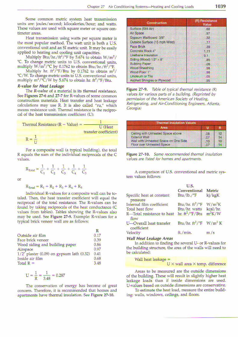
Tlre R-?al!e of a material is its thermal rcsistallce.See Figures 27'6 and 27-7 for R-values oI some con'rmonconstruction mate als. Heat transfer ar'rd heat leakagecalculations nlay rise R. It is also called "m," R'hichDreans resistance unii. Thermal rcsistance is ihe reciprocal of the heat tfansmission coefiicient (U):
Thermal Resisiance (R - Value) =U (Heat
transfer coefficient)
For a composite wali (a typical building), the totalR ecluals the sum of the inclividual reciprocals of the C
Filue 27-9. Table of typical thermal resiitarce fR)values lor various parts of a building. lReprinted bypermissian ai the American Saciety af Heating,Refrigetating, and Air-Conditioning Engineers, Atlanta,CeorBia)
Figurc 27-1O. Some rccammended thermal insulationvalues are listed far homes and apattments.
A comparison of U-S- conventional and metdc sys-tem values folo\,'s:
IU
1 1 1 1 1cr c, c3 cr cr
Rrot.r : Rr + R, + Rr + Ra + R.
Individual R-\'alues for a composite !\all can be to-taled. Then, the heat transfer coefficient will equal thereciprocal of the total resistance. The R-values can befound bv takint reciprocals of the heat conductance (Cvalues from tables). Tables showing ihe R-values alsomay be used. See Figule 27"9. Example: R-values for at_vpical brick veneer h'all are as Iollows:
ROutside air film 0.17Face brick Yeneer 0.39Wood sidinS and building paper 0.86Airspace 0.971/2'plaster (0.09) on gypsum lath (0.32) 0.41lnside air film 0.68Total R = 3.48
- . I I ^ ^ - -R 3.48
The consewaiion of energy has become of greatconcern. Therefore, it is recommended ihai homes andapariments have thermal insulation. See Figure 27-10.
U-Overall heat iransfer Btu/hr. ft'zl'F W/mr K
Velocity
Spe.ific heat at constant
Intemal {i]m coefficieniTotal heat flor,'R Total resistance to heat
flow
u.s.Conventional MetdcBtu/lb./'F kj/kgK
Btu/hr. fi'zl'F w/m':KBtu/hr waits kcal/hrhr. ft']ii 'Fii Btu m'?K'/W
wall Heat Leakage AreasIn addition to {inding the several U or R-values for
the building structure, the area of the H'alls will need iobe calculaiedl
Wall heat ]eakage =U x wali arca x temp. difference
Areas to be measured are the ouiside dimensionsof the building. fhese r{'ill resuli in slightly higher heatleakage loads ihan if inside dimensions are used.U-r'alues based on outside dimensions are conse ative.
To estimate the heat load, measure the entire build_ingr r\?lls, windoh's, ceilings, and floors.
Ceiling wnh Unheaied Space above
Wallwith Unheat€d Space on On€ SideFloor over Unheaied Spa@

'1040Modem Refrigefation and Air Condjtioning
To measure walls, take the outside Iengih and widthof the house and th€ inside ceiling heiSht To determinethe total surface aiea, first m€asure the distance arcundthe house. This will be the lmgth plus the width, plusthe length, plus the width. L + W + L + W = Perimeier
Total wall area is obtained by adding th€se valuesand muliiplying by the wall height. For examPle, ahouse, as sho .n in Figwe 27-1L, \s 24' x 32' (outside).It has an 8' ceilinS. The total area will be:
P e m e t e r = L + W + L + W= 32' + 24'. + 32'. + 24',=112'
Area = pedmetet X hei8ht: 712', x 8',= 896 fc
This is the totalwall area. Window and door areas mustbe subtracied.
Eigurc 27-11. Drawing af one'story home shaws wall,window, and door areas. Buildinq is 32' (9.8 n) long by24' (7.3 n) wide. Roam height is 8' (2.44 m). Five\\,indows are 4' (1.22 m) high by 2' (0.61 m) wide. Twodoorc are 7' (2.13 m) high by 3' (a.914 n)wide. Laryewinclow is 1' (1.22 n) high by 6' (1.83 n) wide.
windows and DootsKnowledge of the area of each window is needed
in a heat leakage calculation. It is determined by mea-sudng the opening in the wall. This would be the dis-tance to the bdck edtes, as shown in Figure 27-12.
Windowconstruction varies considerably Windowsma) be sirgle-prne. double-Pane u<ing a slorm windo\^o- permane'1l double-Pane. Lnergy-efficienl $rndos-may even have three Permanent layers of glass. SeeFisure 27-13.-
The pemanent window (single- or double-Pane) iscalled th; p mary window. An additional fiamed Paneof glass may be set into place to Provide added insula-tron. lhis i5 Ldlled a 5.orm windoh or -dch
The most efficient window construction is the Per-manent double- or triple-Pane. Two or three Panes of
Slass with sealed airspaces between Panes Provide ex-
6,ffil&r
Figurc 27-12, Typical double-hung window showinBwidth and height of windaw opening.
:;
W, i l
. la.
B
u,t:..
a:,i
Storm Sash lor Double-
n)
|,i
:
Eigure 27-13. Window construction. A Dry air.BlPrimary glass. C-storm glass. D-Metal sash.E Sliding windo,A' and storm with screen.
cellent insulaiion. This airsPace is dehydrated andevacuated. Then it is usually filled with nitrog€n or someother dry gas to prevent sweating (condensaiion).
Windows are installed in a variety of ways. Somepossibfities include:
. Fixed (picture windows)
. Single- or doubte-hung (where either one or boihsashes move up and down)
. Sliding horizontal or casemeni (hinged on one sideand olen out with a crank mechanism)
c t ;

Chapter 27 Air Conditioning Sysiems-Heatjng and Cooling Loads 104'l
The frame around windows may be made of woodor metal. Vinyl-clad aluminum fram€s are used tominimize frcsiing. The R- and U-values of window paneassemblies are shown in Figure 27-14.
Figwe 27-14, Thermal resistance (R) and heat transfercoefficient (U) af various window pane assemblies arespecified. (Andercen Carp.)
Warm air wi condense on cold suffaces. Thisbecomes a problem with windows and walls. Conden-sation occurs due to a combination of both temperatureand reiative humidity, (dew point). For example, atu at70'F (21'C) and 40% relaiive humidity, contacting a win-dou al 45'F r fc). causec conden<drior. l h i> proce,s i -shown on the psychrometric charts in Chapter 19.
To prevent condensation, reduce ihe relative hu-miditl. oi raise the temperature of the dass surface.Lowering the relative humidity in the home may not bepractical or comfo able. Another solution would be ioadd a vapor barrier beiween ihe inside surface of theh'indow and the room air. It will also serye as addedinsulation- Many companies make products to providea temporary vapor barier Ior the cold season.
The area used to calculate heat leakage Ior a doori . rhe \e:ght l imes the l^, idr\ of t l 'e door opening.
Doors are constructed in a varieiy of desiSns. Theymay be made of solid wood or of wood venee$ o\:erfoam cores. Recent energy efficient doo$ are constructedof a metal shell filled with insulation. Some doors havehindows as part of their design. Large sliding glassdoors are called patio doors. They are rcsponsible for20% of solar heating and heat leakage in some homes.
Proper door-io- 'a11 sealing is very important tominimize heat leakage. The use of a rubber weather-st pping is common practice. On metal doors, a mag-netic weather-stripping, similar to that used onrefri8erators, can also be used-
When computing the wall heat leaka8e area, addthe area of the doors in the outside walls to the area ofthe windows. Then, sribiract this amount from the totalwall area.
ExamplelBack in Figur€ 27'11, there are five windows mea-
suring 2' x 4', two doors measuring 3' X 7', and one\.indo$, measuring 4' x 6'.
2 x 1 t 5 : 8 x s = 4 A f t 23 x 7 x 2 = 2 7 t 2 = 4 2 #
The nei wall area is
E96 t'C - rc6 t'C =7e0 reThe two values, 106 Ii'?of windo$' area and 790 ft2
of wall area, will be used later to find the building heatload.
ceilingsCeilings generally are made by fastening drywall to
the joisis. Figure 27-15 shows sei'eral typical ceilin8 con-sEuciions. Heat leakaSe will be considerable if the joisisdo not have a floor over them. It will also be consider-able if there is no insulation beh^.een the joists. SeeFigure 27-7 for U-values for ceilings.
Using ihe sample house in Figure 27-11, ihe ceilingarea is calculated as follows:
C e i l i n g a r e a = W ! L= 24' t 32'= 768 fr2
E
Eigne 27-15. Ceilin1 construction. A-No iloot orinsulation. B No floor, 2" insulation. C No floor,4'insulation. D-Floor, 2" insulation. E-Double flaor, noi nsu lation. F-F loor, 6' insul ation.
4 X 6 X 1Total opening area : 106 fF
The totat wall area is 896 ft'?

1042 Modern Refriseration and Air Conditioning
Basement Heat LossHeat losses or gains for basements vary wid+
Fieure 27-16 shows the heat loss for a basement builtfiv! feet into the ground. The deeper the basemenL theless the heat loss. It is usually assumed that a basementis at 60'F (16"C). Leakage through the basement flooris usually noi calculated. The heat leakage load is cal-culated through the fust floor of the building (thebasement ceilind.
EiglJJe 27-'16. Tempenture conditions and constructionof buildinB with basenent.
Buildines built on a concrete slab have differentheat losses than those built with a basement. SeeFigwe 27-17. With the building on a slab, heat lossabove ground is calculated in the typical manner. Iceand ftost may form around the outside of a slabbuilding. One method for minimizing this is to use adeid urethane slab. The slab should be at least 2" thickand installed 2' to 4' i]l the ground. Figure 27-18 showsa t\''Dical installation.'-Heat
losses for the slab design are usually cal-culated as Iollowsr The perimeter o{ the building isdetermined. The total lentth is multiplied by 18 Btu/hr.for each foot of len$h (0"F I 18"C1 design temperahre).
Another popular type oi foundation leaves justenough space between the floor and the ground to al-low access. This is referre d. to as a qawl space. T\e eatt}].floor of a clawl space should have a vapor barrier on it.(This could be plastic sheeting, roofing PaPer. etc.) In ad-dition, the floor can be insulated from undemeath toprovide maximum thermal protection. A crawl spacemust have suJficient vendng to minimize moisture Prob-lems in the summer. The venting also minimizes the
Fi$we 27-17, Tempeature conclitions and consttuctionof building built on concrcte slab.
Figure 27-18. A method is shown for preventing icea;d frost fron fotming around perinetet ol buildin7 builton slab. A'_Rigid urethane insulation. lnstall as close tobuilding as convenient.
amouni of cold air enterint in the winter. Vents withdampers are installed to serve this dual purpose.
R€cent constructlon pmctices use vapor barriers(plastic sheeting) between the basement walls and thesurrounding ground. Refer to the American Society ofHeatin& Refrigemting and Air-Conditioning Engineersrecommendations for additional data.
Sun Heat toadH€at energy from the sun adds considerable heat
load durint the summer. The suJl's mys in the northem

, hdo .er - a o -d ion i , r \ . . pn . -F Ipd Inq ond .oo I -odd. 1043
hemisphere shine on tlle east, sorth, and west walls.They also shine on those roof sections that are exposedto the sun. Therefore, r 'hen computing total heat load,heat from the sun must be considered:
. On the east wallin the morning.
. On the south wall all day long.
. On the west wall in the afternoon.
This is shorvn in Figure 27-19.
Unless windows are prctected with awnings, use atemperahue of 15'F (8'C) higher than outside ambienttemperature for corect results. Also add thls amount toambieni tempemture to take care of the effect of the sunshining on walls.
Approximate values obtained by using the 15'F(8'C) temperature correction genemlly are usable. How-ever, there a(e many special cases that reqldrc carefulstudla Consider the changing position of the sun relativeto the su aces oI the building. Also consider the iimelag required for this heat to reach the building's interior
Heat LagIt takes time for the heat to iravel through a sub-
stance that is heated on one side. Il€df ldg is the timen€eded for heat to travel thrcuth a substance that isheated on one side. The sun heats the outside wall of abuilding. Hol^.ever, several hours pass before this heatreaches the inner surfaces of the wall. In normal build-ings, this time varies between three and four hours. Withwell-insulated or thick r{-alls, ihe sun may be gone bythe time the heat "soaks" through.
In the southwesL adobe walls are made cluiie thick.The sun heat moves into the wa11 wlile the sun shines.The wall is thick enough to prevent the heat ftom reach-ing the interior. Dudng the nighi, r -hen ouidoor tem-peratures fa1l below those inside, the heat flow reversesit-el f djrd frdvel. ou.!vard rhroLrgl- rhe w.- .
The south wall receives sunlight the eniire day. Theeast and west walls receive sunlighi only a small pe odof time. Howevet the south wa11 is not as sirongl]' af-fected as the east and west walls. This is because therayscome from overhead. The lenSth of daylight alsochanges throuthout the season.
This heat lat causes the rooms to be heated evenafter the sun goes below the horizon and the outdoortemperature drops. See Fig]lle 27-21.
- oulerwal, F - - - - - h n e r w a l l
I 7 A.M.
Figwe 27-19, Sun rays and their impact on the walls aia building during a 12 hr. period.
The sun releases different amounts of heat tosurfaces, depending upon ihe part of the world inwhich the buildhg is located- The approrinate maxi-mum hFdt B-dir f rom the--un rs 130 Bfu per hr per h(97 watls/ft't10a0 W/m'l). This is for a black su aceat right angles to the sun's rays near the equator(tropic). Any oiher color surface ai an angle to the sun'sravs will rcceive less heai.
At the 42nd parallel (a line goint through Nel^' YorkCiiy, Clel'eland, and Salt Lake City), the maximum heatfrom the -un. rav5-i . abolr l t lc Bfu pe' hr pe' fL ' ] ,q2r.atts/ft' 1993 W/m'l).
Much of the heat from the sun is reflected back intothe atmosphere. Figure 27-20 indicates the windor ' heatgain for windows facing different dircciions. fhis heatgain musi be removed lvith air conditioning.
figwe 27-20, Heat absorption when sun is shining on
Figwe 27-21. LaB in interior',\'a|l temperaturefallowing exposure to sun.
Heat Sources in Buildin8sHeat sources may or may noi be a benefiL depend-
ing on whether it is sumrner or r\/inter. There arc sev-eral sour.es of heat besides inJiltiation and surl load All
124
1 1 0
100
90
80
TA
6 9 1 2 2 1 A 1 2 1 5 1 3 6 8

1044 Modem Refrisefat on and Air Condit onlng
sources must be considercd when liSuring the comfocooling load.
Durnrg the healing season, the heatinS sysiem isaided by these other sources. Practically all energy ex-pended in the building becomes heat. Yet, these sourcesare usually ignored when figudng heat loads of smallbuildings in the winter. They are small amounts com-paied to the total heat load in temperate zones.
Howevet when Iiguring the suruner heat load(cooling heat load), all heat energy sources musi be con-sidered. (ThG includes heat released by human beings,5ro\p-. . ighlr ele.rr ic molor). er. ) Figure 27-22 'hoh5some of these heat sources. Notice that the two sourcesof heat sensible heat tain and latent heat gain-areitemized. Lateni heai raises the relative humidity.
Dunng the cool 'ng season. .he hedt relea:ed b) Per-on5 mu.t be laker rnio accourt . The rrea. relea)ed byone person weighing aboui 150 lb (58 kg) is 74 watts(253 Btu/hr.) rThen at rest. It is aboui 440 watts (1,500
Btu/hr.) r.hen that same Person is working About 25%to ,15% of this heat is by moisrure evaPoraiion. This is acombination of moisture ftom the respiraiory systemand from the skin.
window Heat Load for CoolingThere is considerable heat flor^' through ordinary
wrndou gla--. lL i - dppro\ imaiel \ three l i r re. a" Sredta- fow lhroug\ urdrndr) re ' ;dcnt idl roofr a ' ]d cer lmE'Therefore, a conditioning areas containing a largeamount of ordina!, glass can become a problem. To re-duce the heat conductivity through glass, a storm sashis used. To reduce the solar heat throtgh 8lass, sPecialtypes of ghss with high heat-reflecting qualitles may beused.
Specral heaFab5orbine qla55 ldn reduce the 'olarheat 6ao by a' much as rdd enorner merhod r> to u-eglass tinted a bluish Sray to reduce the solar glare andcooling 1oad.
Roo{ extensions over a window will rcduce th€ areaexposed to the sulr. Double-glazed windows exposecl tosun ravs reduce solar heat absorption by 15% Awningsto shade glass windows exPosed to the sun can reducethe heat load by 55%.
Humidifier Heat LoadDuring ihe heating season/ water vapor must be
added to the aif for comfortable conditions Heai to Pro-duce ihe water vapor may come ftom heated air, fumaceheat, or electric heat.
The amount of heat needed is figured as followsiThe number of volume chanSes Per hour musi beknown. Generallt one change Per hour is satisfactory forhomes. The number of gains to be added per Pound ofait to obtain the required relative humidity must beknown. See Chapter 19-
FormulaiPounds of air per 24 hours
x increase in Srains : grains/day
$./day/7A00 gt./Ib. =lb of water/day]b. of water/day/8.34 lb./ga|: $I /day
To calculate:
l n . o / ^ )\o lume charge- hr ' d- ; ;= - 8 i l /dd)' JJ,UUU
Example:A home has 12,000 ft3. The grains to be added Per
pound of air to change ihe air ftom 35'F (2"C) and 907"iiH to 72'F (22"O and 40% are 20. Find the total gallonsof water to be evaporated Per day.
Solution:12.000 z 1 20 240,000 -- , ,: : . - . . J ga l . day
33,000 33,000
Heai Loads
EnergyBtu/hr,
E ec l rcMorors, E eclric;/Hp in Foom
tvolors, Electic/Hp Oul oi Foom
UP IA 112U P T O 3UPTO 20UP JO 1/2I.JP TO 3U P T O 2 0
341542003700295017001 1 5 0400
3415
102012301080880500340120
1020
1 1 0 0550
320160
300675
88198
36400
1 0120 800 230
Slnirg
Danc ng
370700-1500
2000
1 1 0204444
590
140
figfie27-22. Heat released by variaus enegy sources within a building

Chapter 27 Air Condit onlng Systems Heat n8 and Cooling Loads 1045
The amount of heai (in Btu/hr.) needed to evapo-rate the water is found as follows:
Formula:Volume of house
\ (hd rSe ipe rhou r I3 . sq f r o fa l r / l b .x (Br./lb. indoors - gr./lb. outdoors)
x 970.3 Btt:/lb./7D00 gr,/1b : Btu/hr.
volume chdnge.. hr. F^-iL - sr, n"
Example:Using the same numbers as beforc, the volume is
12,000 ff. The gains are 20. Find the required hear.Solution:
12,000 1 20 240,000 ̂ ,-- - ,_ r , . hh, hr97.75 97.75
Air Conditioner Heat LoadFigure 27-23 is a form used to calculate the coolinS
heat load for a room. By multiplying the area of thefloors, walls, and windows by multipliers, the amountof required ener8y can be determined. The nultipliersare obtained by multiplying a typical U-value by thetemperature difference. For example, the wnrdows (in
the shade) have a U-value of 1.25.Ifthe iemperature dif-ference is about 12"F (7"C), the multiplier becomes 15.
12x1.25-15
The following is a way io make a rough esiimate.The chart identifies COP, which is the ratio o{ outputdivided by input. The output is ihe amount of hearabsorbed by the system. Input is the amount of energyput into the system. Remember iha! on the average,a medium-size room needs 5000 to 6000 Btu/hr oIcooling. The average window conrJort cooling unit willadequately handle the cooling bads as follows:
0-6000 Btu/lt = l/2 L|P., COP = 4.716000-9000 Btulhr. = 3/4 hp., COP = 4.719000-11,000 Biu/hr. = t hp., COP :4.32
27.1.3 Total Heat LoadIt is best to set up total heat load calculations in
table form. Figure 27-24 shows a iypical heat load cal-culation for a 24' x 32' (7.3 m x 9.8 m) house. Refer toFigure 27-7, Note that the temperaiure difference Ior theceiling is only 35'F (19"C). Also consider that ihe roof
Enefgy Requlred lor Cooling
Heighl:
No.r - Facinal S z e : - x -
suf exposed ( rteror shad€s)
Sun exposed (awninss)
East, Nonh, or shaded:
6 0 = - B l u / h r - w a t i s4 0 = - B i u / h r - w a n s
3 5 = - B i u / h r - w a n s15 =-Blu/hr . -wat ls
Souih, Wesl exposure:
Thn wal a lexposures:
-sq, f i . x 8 =-B1u/hr . -wat1ssq. f r . x 5 =-B1u/hr , -waf ts
- sq. fl. x l0 = - Blu/hr. - wails-sq. f l .x 4 = - Biu/hr . wal ts- sq. n. x 10 = Blu/hr. - walts
Btu/hr. - walts- BtL/hr - walts- Btu/hr walls
3 =8 =
2 0 =
- s q . f t . x 4 = - B l ! / h r - w a n s
- sq. l x 400 = - Blt/hr wans
x 3.4=-Btu/hr . -wal ts=-Biu/hr . -wal ts
Total: - Btu/hr, walts
Figure 27-23. This table can be used to cletermine the cooling needed for a typical residence.

't 046 Modern Refr lgerat ion and Alr Coid i t ion ing
Figli]e 27-24. Typical heat load calculation for2r' x 32' hane havinB an 8' ceiling heiSht.
serves as added insulation. it keePs the attic temPera-ture higher than the outdoor iemPerature The attic tem-peratuie can be accurately calculated by makint theheatleaking inio ihe attic in winier equal the heat leaking out
Ceilins area x (70'F - [attic temP ]) x U.- = Roof area x (attic temp. 0"F) x U..
Wherer U. = U-value of the ceilingU, = U-value of the roof
Note that most homes have an 8' (2 4 m) ceilingheisht. Manv homes may have 9' (2.7 m) or 10' (3.0 m)tusi floo' ceilings. Va.lt;d ceilings require that the totalwall area be calculated by adding the dimensions ol theentire wall, including the "iiangle area" at the top ofvaulted rcom's walls. The lorver ceiling helPs Preventtrapping hot air near the ceiling The hot ceihlg ail canbe used for heaiing
Each heat leakage value is obiained by means oftheIollowing formula:
Heat leakage =area x U-value x temPerature diJference
A qu'cl nethod u"ed to eshmite total hFar -odd'
sJrown in Figur€ 27-2q. \ote thar lhe hed! load i ' brsed
Resldenlial Forced Airsyst€m Design Guide (For Estimatlng PuQoses Onlv)
rzoo 6r3oo P
Eigurc 27-25. APptoximate heat laad chatt far winter heatinS and summer caoling is bated on valume oi conditionecl
space. lDetroil Edisan Ca.)

I h d p e r 2 a i r , o n a i r o - B ( ) ' l F m - l ' F a l _ g " n d ( o o l ' r S l o d d 1047
Residential Forced Air SyEtem Design Guide
Air Distribuiion sizes
SupplyDuct ( ln ) Outlel (ln.)
Grille(Da.) Equiv
Ceilinq(Dia.) (Dia.) Eou v.
200300400500600
4
5
4112 t 34 1 1 2 t 34 1 1 2 x 34 1 1 2 x 3
2114 \ 10
6 x 1 06 r 1 06 x 1 06 x 1 0
66666
700800900
10001 1 0 0
55666
8 t 3 1 1 4
14 x 211141 0 x 3 1 / 4
2 1 1 4 t 1 02 1 / 4 x 1 02114 \ '102 1 / 4 \ 1 02 1 1 4 \ 1 2
4 x l 0 66666
6 x l 06 x l 06 r l 06 x 1 06 x 1 0
666
8 x 6
120013001400I5001600
667
7
6 x 5
8 x 5
2 1 / 4 \ 1 21 0 , 6
1 2 x 61 4 x o
6 x 1 0 7III
17001800190020003000
77
T 112
x 6
13
4 x 1 24 x 1 2
6 t I888
I ^ 1 1
40005000600070008000
91 0
1 1 1 t 21 2
8 x 8I x 1 18 x 1 38 t 1 48 x 1 6
6 . t 2 46 : 3 08 x 3 08 / 3 0
1 8 x 1 8
l 11 21 3
1 5
8 x 1 88 x 2 28 \ 2 4
1000012000140001600018000
2000025000
l 3
1 4 1 1 21 51 6
1 8
a ! 1 88 \ 2 24 , 2 48 r 2 68 r 3 0
8 x 3 48 x 3 9
1 8 r l 8
2 4 \ 2 4
2 4 / 3 0
2 4 x 3 02 4 t 3 0
1 61 8202020
2222
8 x 2 aS x 3 6S x 4 6
8 x 6 0
Filure 27-26. Duct sizes basecl an estimatecl values faund in Figurc 27-25. (Detroit Edisan Co.)
on room volume. The table also includes cooling. Amethod for estimating duct sizes is shown in Figure27-26. This table is used as a companion to the heat loadtable. For a given rcom volume, a recommended supplyand retum duct size is 8iven. Outlet and retum 8rillealeas are also shown. More information on the calculaiion of Droper afu distribution svstems is found inChapter b. Standard worksheets aie available Ior calcu-lating total heat load. See Figtre 27-27.
Heat gain calculaiions to determine the total build-ing cooling load are similar to heai loss calculations. Thetemperature difference is based on the localiiy beingconsidered. Indoor tempefature is usually designed tobe 75"F (24'C) at 50% relative humidiiy (RH). Therefore,if the sujnmer design temperature is 100"F (38'C), thetemperature difference is 25'F (14'C). This temPerature
dilference is for Ioad calculations only. In practice, a 20"F(11"C) difference is recommended.
Other heat sources must be considered. Sr.m load,electrical load, and occupants are ]arge enough sourcesof heat to be included in the heat load calculahons.
27 .2 Design Temperatures
Contact the local weathet bureau or lo€al chapter olthe Amedcan Societs/ of HeatinS, Reftigerating, and Air-Conditioning Engineers (ASHRAE) for data on desiSnrcmperarufes.
Always choose the outdoor desiSn temPelatures(ODT) on the low side. Heaturg plants that are over-worked cause excessive stack and chimney temPeraturcs

1 048 Modenr Rei'iserat on and Air co rd ltion ng
Besidential
State- Zp
WINTER: Inside Design Temp- 'F-Outside Oesign Temp- 'F = Healing TemP Ditrerence- 'F
SUMTIEF: Oulside Design Temp- 'F-lnside Design Temp- "F = CoolingTemp Ditlercnce- )F
Whole House Worksheet
HEATING COMMON DATA SECTION COOLING
SUBJECT
GROSSWALL
DOOFS &WINDOWS f iabeAor B)
NETWALL
CE L ]NG
FLOORS
f f i t ' f , - , ! "TXT=" ! t t i t t "x 0 18333 x 0 01833 : x
SUB-TOTAL BTUN LOSS (per 10 F)
ADJUSTMENT FACTOF (Tab e C)TOTAL BTUH LOSSpEopLE- Joo BruH Ge r 1}i!g5,"'"',;'l'""' ' . . . .APPLIANCES BTUH 1200
SUB ToTALBTUH GAIN (room sensible only)
DUCT LoSS/GAjN FACTOB (Table F)
sUB-ToTALBTUH (Sens b e Gai.)
L4OISTUFE F EI'IOVAL (s!b lola x 1.3) x 1 . 3
TOTAL BTUH LOSS/GAIN
TABLE A.HEATING-OOORS & WOOD FFAME WINDOWS(PEF 10.F)For s iding glass doors - use lactors forthe same lype wfdow
TABLE B-COOLING-DOOBS & WINDOWSFactors assume wndows have nsde shadng by drapeies orvenenanblnds ard siding glass doors arelreated as wndows
TABLE D_INFILTFATION MULTIPLIEBSwinter Air changes Per Hour
Summer Air Changes Per Hour
slls e Pane9.90 10.451 1 5 5
4.75 5.25 6.50
6 0 9 7,25
3.41 3 3 5 4.90
3.80 4.39 5.46
1 1 . 0
5.0Sky lgh ls 11.0711.6912.92
6.65 7.35 4.75
4.603.20
1.90
(F-5)W/Slorm 1_70
TABLE C-ADJUSTII,!ENT FACTOFS{HEATING50 305
TOTALS
Fisvre 27-27, t-Jse this ||atksheet to catculate heat tasses and p.ains. (The Tnne Canpanl lconLinLled, next page )

Chapter 27 Air Condirioning Synems-Heating and Cooling Loads 1049
TABLE ECONSTBUCTION FACTOBS HEATING & COOLING
ryPE OF CONSTRUCNON 15. 20. 25'
Walls-wood trame w/ sheering & siding,von€s or other linishA) No islaloi rr2 GypslmBoad
B) Frr cavib/ ns!aroi + r'2 GypsumBoad
c)Ri3cEvryhsurarion
Dr F 13caviyinsdario^ 3/4 Bead eoa'n (R 2.7)
E) Rrecavry i&aron + r2 Gypslm Boad
F) Fnscaviv nlaron + 3'4'Entuded Poy
a) Above Eade No ns!aror
D) Beron qrade No 6u roi
CEILINGS (Use Sq. Ft.)
Dl 5rr 6rr, rnsuraron F 1e
i) carhedE tpe No nsraron(rcdrce iiqconbnaron)
4 carhedd ryp€ Frr l,oorca ins..ffbiaioi)
() carhad'a \ipe u le (,ooite rnq6mbnaronl
L) Carhdd,a rype F 22tootcerhq.onbnaion)
Mr caihedErtpe R.26(rco'ts nocombmrioi)
FLOORS (UseSq. Fl. OF Linear Ft.)
FrooE ove, unFndrionsd spa€ ($.3q. h )Al owba*medo,endosedc6w spa.e l iorveiiad]
B) Sameas A + Rrr isuaroi
c) sams as A +Fieinsuraroi
D) oYe, v4rEd spa€ or saraqo
E) over venred space or qaGqe + a 11 insurarion
F) o€r!6id <pre orqa6qe F le naa on
BaFmeni FLoors (u.. 3q. ft.)
concieresrablloorunh€bd (use rid..rfi,)
concrcbsrablloorduciinsrab(us.rrne n.)
HEAT LOSS & GAIN FACTORSTABLE F
Calcu ale only I duct s localad in 6n unconditoned spaco
ESTIMATED PROCEDURES
reislh 1ps ftbd n r@r sasab
a md B by m! rF\ fs ss a€a d s as aft d@re te
10 oi vod$et m! tpt se are4 : h
DUCT LOSS MIJLTIPLIEFS
Case I " Supply An Temper.tuE6 Below 120!F
OpenCcq soaca a2
DUCT GAIN I\iULTIPLIEBS
Figurc 27-27. Continue.l

'| 050 Modem RefriSeration and Air Conditioning
and may cause fues. Ove$ized units wiII be less efficient
and waste energy.I he OD I is never a' low as the lowest temPeraLure
rccorded for the area. This is because these extreme lows
are usually o{ short duration Residual heat in the build-ing usually enables the furnace based on th€ desiSn tem-perature to handle the load.
ASHRAE has a method oI fisling otltside desiSnlemperaLur5 (ODT,. In this m€thod. the Om varieswith lafirude and ele\ation. When worling hiih desiSntempeFtures, use the current values (These are avail-abla from the local ASHRAE chapter')
ASHRAE charts give three diJferent values for eachlocality. The lowest temPerature is for small (domestic
and office) rninsulated buildings The 99% temPeraturemeans that the outdoor temperaturc is at or above thistemperature gga. of lhe time lt can be u.ed for weli-con:iru.ted and well rn"ulaled building' ha\ing a stan-dard number of windows.
A 97.5qa v^l\e also Siven for each locality meansthat the outside temp€mhne is above the value listed97.5% of the time. It f used for large buildings with con-siderable themal capaoty and smali total window area
Example: Dehoit once used 10"F (-23"C) as ODTfoi aU buildinss. Now it is recommended that 0"F(-18'C) be used for smait, uninsulated buildings. Forwell constru€ted, insulated bldldings with a standardwindow area, +4"F Q"C) (99Ea (actor) is used. For largebuildings with a standard number of windows, +8oF(4'C) (97.5% factor) is used.
If the Inside Design Tempemture (IDT) is 72'F(22'C), an ODT of 0"F (-18"C) means a 72'F (40"C) tem-perature difference rTD). The qroo ODT I r4'F [ 2'Cl)mean' a o8"F tl8'C) TD. Ihe c7.5ad mearb a b4"l- (35"C)
TD,
T r a t a:: 100 : _: 100 : 1170f t / z
This represents alr 1190 savings in equipment size on ihisinstallation.
In many buildings, certain areas such as closets,hallway-, dnd attics dre un}leated. Theie -Pdces receivetheir h;ai from heat leakage through Partitions, ceiLings,and floors. These urheated areas are assrmed to be halJ-way between the indoor desigr t€mPerature and theoutside desig4 temPerature
27.2.1 Degree-DayMethodThe desr€e-day method is used for determining
fuel consumltion and heating cost during a season ltdetermines, by previous weather records, the averageiemperature oi e;ch day during the season. It also keePsa reiord of daity tempemture during the season understudy.
The degree-day method uses a 65'F (18'C) indoor
temperafure a> d standdrd. T[ the average temPeralwe
out. ideis l5"F r-q"C). the temperdturedif ferencewould
be 50'F (28"C). Therefore, that day would have 50
desree-davs. tach degree-day requires a certain heatloj i ro keep the inside temperdture at b5eF I lSoCr'
Knowing the number of degree-days since a fuel oiltank was frIed enables you to accurately calculate theanoult of fuel lefi in the tank. lf the degtee-days for aseason are known, the heating cost for that season canbe calcldated.
27.3 tnsulation and Vapor Barriers
A large number of diff€rcnt insulating matedathave been-developed for buitdings lt is necessary thatthe insulation reduce heat loss In additio& vaPorbard€Is should be included in the insulation or in thewals. Th€ barriers rcduce moisture travel through th€waI.
lL i< ven imporldnt thaL h) groscoPi. rmoishne ab-
"orbent) ins! ation i5 hermedcally sealed Alurrlinumeheei or lared PaPer are tro PoPUlar cealing materialr'Even insulation noi dffecled by morshxe should be va-por sealed. fhe in.ulahon wi lo'e much of its insulat-ine vaiue iJ iL tuls up with moi-ture. Thi- is parficuld-rlyim;ortant in cooline applications'
The in.ularion seiecLed should hdte suJlicientsfreng.th to cupporl iLsell and not 'hrirk or 'ettle. Tl mu'tnot d"eleriorate-in the Presence of moFture ll murt nol
have any unPleasant odor' The insulation should bevermin-prcof and fue-resjstant
Th; type of insulation used dePends, to some ex_tent, on th; method of apPlication. Easy-flowing bulk in-sulation can be blown into the sPace between the studsof an eristin8 buildinS as shown in tig$e 27-28. Forne\r buildings, rigid in.uldiion can be used
Flexible insulation is easy to install in new construc-tion or io existing attic sPaces. It comes in rolls and eas-ily conJorms to any irregularities in the construction.
Fisure 27-28- Easy-flowinB bulk insulation being blowniim an aftic area. (Owens-Corning Fiberglas Corp.)
Chapter 2T Alr Conditioning Systems H€ating and CooliiE Loads 1 0 5 1
The Mineial Insulation Manufacture/s Association,lnc. (MIMA) recommends certain insulation for electri-cally heaied and air condiiioned homes:
Ceilings R-19 through R-28Walls R-11 througll R-19Floors over unheated spaces R-11 thiough R 19
The above R values dep€nd upon the location. Usethe higher values for locations abov€ the 42nd parallel.R-22 and R-13 values are recommended for special situ-ations where exha insulation is necessary
27.3.1 Ponded RoofAn ordinary roof may be heated by the sun to a tem-
perature of 100'F to 150"F (38t to 66t). Ceilings undersuch roofs will become warm and radiate this heatthrough the space below
Many buildings with flat roofs are provided withsome summer comfort coolngby rlsi^g ponded rcofs. A2" to 3" (5 cm to 8 cm) pond of water cove$ the roofsurface. This type oI cooling is especially well suited toone-siory factory and market buildings. To be effective,the ioof area should be as large as the floor area.
The cooling effect comes ftom the evaporation ofwater from the roof. Naturally, ponded systems arc mostelfective in areas having a high tempemture, low rela-tive humidit, and bright sunshine. By pondin& rooftemperature may be kept below that o{ the su ounding
Ponded roofs require a means of maintaining aconstant level oI water on the roof, Drains are neededto take away excess water due to rain- If the roof is1arge, wave breakers arc needed to prevent wavesftom foming under high winds. The waves couldcause a large quantity of water to be blown off the rcofedge.
A ponded roof may reduce the required at condi-tioning capacity by as much as 3070. However, the addedweight on the roof will result in higher constructioncosts. A ponded roof should never be added to an exisfing building uiless the rcof shucture can support theadditional weight of the water.
27.3.2 Building Insulation and Ventilationfor Electric Heating
Eiectric heating is becoming more popular Prob-lems in electric heating usually involve the need for in-sulation or ventilation. Excess relative humidity also canpose a problem.
The cost of heating is another factor to be consid-ered. Usually, itcosts more toproduce a unit ofheatelec-trically than with most other types of fuels. ReducinSheat loss through windows, walls, floors, and ceilingswillreduce the cost oI elecdc heaiinS. Therefore, install-ing efficient insulating mateiials and double-glazed win-dows will help cut the heat load.
Eleciric heating requires a rvell-insulated and tighistmcture. Sometimes, however, this adds to the ventila-tion prcblem. If the building is occupied by manypeople, frequent air changes musi be provided for ven-tllation purposes.
Spaces that are comfort cooled as well as electri-cally heated usually have the elect c heating elementsin the plenum chamber or the air dilct sysiem. Somesystems also have electric elements located in eachroom. lhi, dl lows individual contrul of ihe .pacesbeing heated.
Relative humidity conirol in electrically heatedbuildings is usually differcni than from ihose usinS tuelburning heating equipment. Wiih fuel-buming €quip-ment, a fairly la€e air quantity passes through ihefurnace and out of the stack. Usuallt makeup air entersihe building by leakage around ihe dools, windows, andcmcks in the floor With most electrically heaied struc-tures, buildint consiiuction permits iittle infiltration ofthis naiure. Therefore, there is a possibfity that the rcla-tive humidity is too high. Vapor formed in the space can-not ea,ily e,cape from rhe oLlupred space. De-humidifying equipment may be needed.
There are other Iactors, too, that h+ make the costof heaiing with electricity favorable. There is no dirt orsmoke tenerated in connection with the heating. Drapes,upholstery and woodwork remain clean longer, and thecost of cleaning and redecorating may be reduced. Insome areas/ the electrical companies prcvide a lowerp ce for elechicity used for heating a structure, as an
27.4 Energy Conservation
when reviewing the calculations for determiningheat loads, cetain steps should be Iollowed. Foliovringthese steps can rcsult in signiJicant energy savin$. Theyinclude:
. Use increased insulaiion where possible (especiallybetween roof and cei l ing srr face5l. The incred-e inthe R-value thai rcsults is directiy proportional ioenergy savings in terms of heat loss.
. Use the latest design temPeratur€s when calculating required HVAC system capacit).
. Use proper inside design temperatuies. Theseshould be at the low end of a person's comfort levelin the winter and at the high end in th€ summer.Proper relative humidity and indoor desiSn iem-perature GDT) will maximize overal comfort.
. Eliminate umecessary heat leakage around doolsand window' !1i th good.eahng lechnique..
. Use secondary heat soures (motors. machinery€tc.) as much as possible. This is esPecially truewhen calculatint the required HVAC systemcaPaciiy.
. Use the most ef{icient construction materials, suchas shaded glass, Themopanes, and metal foam_insulated dools.

1052 Mode n Refr geralion ,nd A r Cond troning
27.5 Construction Types and Designs
Building constuction will be a Iactor when design-ing or_seivicing an HVAC system. A building's design
l. ll-e type ol healing o_ dir conditioning svstem2. The an or water distibution neiwork.3. The HVAC instalation.
The technician should have a basic unde$tandingoI the more common construction practices. A typicalresidence can be classified as a singte-floor ilpe (nnchstyle), a two floor lwe (colonial style), or a combinationof both (split-level style). Each style may be built over abasement, a crawl space, or a cemeni slab. Each tl?e ofstructure requires careful consideFtion when insiallingor seFicing an FryAC system. Th€ rnaterials used in con-struction (b ck, aluminum, insulatior! etc) must betaken into consideEtion. They all have significant effectson the heat in8 and .oo|ng of Lhe stru( iure.
The techrrician should also be able to tead construc-iion Dnnts or floor plans. These will provide inJomation useful in making heating or cooling calculationsThis would include dimensions, with locations of duct-rvork and electdcal wires. A tyPical floor Plan with somedimensional infomation is shown in Figwe 27-29. Notethe air conditioner at the center.
The following pangraphs include some specificconstruction differences and their effects on heat loadcalculations. Recent designs and new matedals have rc-duced heat losses and qains.
27.5..1 Roof DesiSn and ConstructionHeat loss through the rool of a building is influ-
enced by several factors. These hclude the tyPe of roofconsbuction, ventilation. and covering. The most com-mon residential roof construction is the pitched roof us-ing a prefabdcated iruss system- See FiSure 27-30. Theslope of a piiched roof is the ve ical se or height ofthe roof compared to the horizontal run. This is shownin Figure 27-30, Slope is Siven as "- in 12." For examPle,a t)?ical mnch style home will have a roof slope of 4 in12- If vou were in the attic and walked a distance ofiwelve feet in the dir€ction of the roof Pitch, the roofheight would have incrcased by foul feet The pitch of aroof is the ratio of the veltical rise io the span (twice therun). It is $ven as a Inction. For examPle, if the totalroof dse is 4' and the total span is 24', ihe Pitch is 1/6(4/24: 1/6). The pitch of a roof is detenr.ined by theclimate and the designer's intedor sPace needs. Themore snow that falls, ihe greater the Pitch should be.This minimizes the sno\r weight at the center. A spliflevel is more likely to have a hither pitch to allow moreheadroom on the second stolY.
Recenilt rcof pitch has become an asPeci of energyconse ation as well- For examPle, the desiSner mustconsider such things as the sPace required fol adequateinsulation with a cathedral ceiling, or a roof Pitch thatwould allow an efficient solar panel system
ProDei ventilation is also impo ant in the roof en-closed irea. Atiics are used to vent household airthrough various ceiling and exhaust fans in the hom€.
tigurc 27-29. Typicat home ltaor plan shows dimensional infotmatian. Note the air condhioner at center.
(@Home PIanners, 1nc.)

Chapler 27 Alr Conditioning Systenrs Heaiing and Cooling Loads 1053
Fisur€ 27-30, Prefabricated roof truss. This unit is called a fink truss
Mosi atiic areas arc vented so that, in summer, cool inpui air can come Ircm the overhangs. This air picks upheat and is exhausted through roof vents or gable vents.See Figure 27-31.
Roof covedngs are chosen based on the sutound-ing climate. Dark asphalt shingles help to absorb ihesun's heating effect du ng winter months. The samefeature, howevet would work against cooling in the
Roof coverin$ for pitched roofs are installed oversheathing. Insulation can be used beneaih the sheathing.Roof coverinSs for flat roofs can consist oI many layers,as in built-up roofing. Inslllation can be a pa of th€ rcofcoverinS.
The R values for pitched rcofs arc hither thanihose for flat roofs. Refer to Figure 27-7. The designmust take this into account, along widr the color of theroot coverrnS.
27.5.2 Wall ConstructionBuilding wall construction has chanSed in the past
few years. Heat leakage and moisture Passage throughthe waII structure has been reduced. Fi8urc 27-32 showstypical b ck veneer outside wall conshuction. DurinSthe heafinB sea.on, ihe inside !dpor barrier is necessary.In summer the outside vapor barier is required. If thedew point temperature in winter (based on the indoorrelative humidity) is rcached between the two vaPor bar-riers in Figur€ 27-32 the location of the dew Point musinot b€ ai the inside vapor barrier If it is, condensationwill take place on the room side of the inside barier. Ifthe dew Doint temDeralure in summer (based on the out-door relative humidity) js rcached between the two bar-
ers, the dew point must not be at the outside vaporba ier. lf it is, condensation will occur on the exieriorside of the outside barrier. For all weather conditions,
Fi'lure 27-31, Roof and aftic ventilation. lf the aftic can be kept cool in the summer, less cooling will be neededinlide the building. A second use of ventilation is to help keep snow from melting on top of the roof, running down,and freezin| at the averhanE. lce dam on ovehanB can force water under shingles

1054 Modern RefriSention and A r ConditioninS
&ck
Figwe 27-32, Brick veneer wall canstruction
the dew point location should be halfway between thenr.o bariiers. This means the Iollowjng should beavoidedrL Tr\ inq lo gel lhP rrrdoor relaf ive humidi iy dbo\e
2l? when , \e ouldoor tempe-ature '5 -20'F
(-29'C) or lower.2. Tr\rng to gei the indoor temPerafure below 67F
( l6"Ct when lhe outdoor ' ondjt ion. are hiSher thdn98'F (37'O and higher than 979. relative humidiiy.ln older homes, an aPProximate 1" afu space sepa-rates the brick veneer from ihe sheaihing. Vaporbariers were noi commonly used.Where vaPor ba iers are used, ihey should be as
.rehi lv -e".ed a- possible. lh:s ndy even mean tarr inSr h"e b;edl. in tha.eal. The barrrer ' ma) be m.de ortarred papet aluminum foil, or plastic film Aluminumfoil hai a_reflection value as well as being a vaPor+ightseal. Idealty, a hermetically sealed (airtight) insulationshould be used in areas where dew point temPeraturesoccur during the heating or cooiing seasor
Another type of wall construction, more commonin warm areas, is the stucco !\tall Stucco is a ihin coafine ofcemeni.Itis spread over concreteblocks or a metalmish and nailed to a wood stud wall This tyPe of fin
ish can be applied by hand troweling or machine sPrayA variely of at1-wood wall constructlons arc also
found. In most newer construction, all wood walls aremade of some iype of hardwood siding. It is fit togetherover the sheathins. The remainder of the wall is sindlarto a brick constuation. Some ofthe more decomtive con-structions include siding made from cedar and redwood
Atuminum siding is nearly as common as the brick
exterior. Aluminum siding is available in a variety of col-
oIS, textuies, and styles. lt is usually installed over the
sheathing material. Newer alurninum siding has a layer
of insulaiion bonded to the back side of the aluminum
The aluminum is installed in an overlapping Pattem'Holes aie provided on the bottom edges of the siding
for moisture release
27.5.3 CommercialConstructionSmall commercial buildings use many of the same
construction prachces and matedals as the t)?ical resi-
dential buildings discussed in this chapter' Foundations,wall and wind6w conshuction, and roof desiSn may be
similai. These tyPes of buildings house small offices or
rctail shoDs.In m'anv instances, the low-dse shoPping center has
replaced th; individually conshtcted shoP. It is now oneoithe largest consumers of air conditioning and refriS-eration p;oducts. These buildings are usually made ofconcreie block set on a concreie slab. Common walls be-tween businesses may be made of concrete block (each
with its own footing) or of a wood-stud construction'Both aliow for floor plan changes to suit the tenani The
roof on th€ low-dse ihoPPing center is usually flat l{'ith
asphalt weather protection The water dlainage on a flatroof is critical. eare should be taken not to interfere
with drainage when working on the roof After a job is
complele, t i -e roo' should be in.pected An) damr8e,lhdt md\ l 'avP o' curred Lo lhe wealher 'eal Protect ionshould
'be noted. Small industdal firms have similar
Hie\.nte bui idrne' dno large indu5Lrrdl bui ldingsare muih nore conpl i \ in their con-Irucf ior ' In lhe)ecases, you should become farniliar with the generalbui ldins design. 5rud) the bluePrir ls Pr ior to doint dry
major HVAC *or\ in\ol \ in8 the bui lding ) ' t rucrure
27.5 Review of SafetY
For safety, a heating system must have enough ca-
Dacity to heat a struclure without becoming tax€d or;verh€ated. The heating syst€m should b€ slightly over-
siz€, nev€r undersize.All designs of heating and cooling systems should
be checked care{ully. Be sure that enouSh fresh air
ent€rs the structure. lt must provide adequate ventila-
tion for the maximum number of occupants. It mustprovide for adequate combustion air during the heating
ln some well-insulated homes, it may b€ necessaryto ooen a basement window or provide some other airinl€t. This €nables the furnace and fireplace flues to draw
properl)-smoLe dnd (arbon monoride \ i l l not he re-
leased into th€ building.
27 .7 Test Your Knowledge
Please do noi wnte ilr this text Place your answem on a
seParate sheet of paPer'1. - causes the majority of heat loss.
A. ConductionB. ExfiliraiionC. InfiiirationD. All of ihe above
Drywal

Chapter 27 Air Cond tioning Systems Heating and CooLing Loads r 055
2.
3.
L
10 .
7.
12.
13.
14.
15.
16.
17.
18.
19.
Which of the following sources of heat are pari ofthe cooling load for a building?A. Heat and air leakage.B. Veniilaiion air.C. Heat from appliances, lights, and occupants.D. A11 oI the above.wlrcn computing total heat leakage, what does "U"rePresent?A Ta -no - rh . - . . l i F f . . " . " .
B. Overall heat transfer.C. Thermal resistance.D. Total heat leakage.Out-rde design iemperd|ure iODTIA. varies wiih latitude and elevationB. provides four different values for each locaiionC. does noi consider the number of windowsD. All of the above.Ahumidifier thatvaporizes one pound of waterperhour will vapodze - gallons of rvater perduy.A. 24B. 12c. 2.88D. 3.5For which heating calculation(s) are heat gains fromlights, motors, appliances, and people not taken
A. Commercial.B. Small buildings.C. Industrial.D. All of the above.What is exfiltration?A. Af thai leaks out of a building.B. An effeci of negative air pressure.C. Air that leaks into a building.D. Both B and C.
usually cause(s) ail pressure difference.
B. Too many exhaust ventsC. The h'indD. All of the above.The-the basement goes into the ground, the
the heat 1oss.A. deeper, moreB. deeper, lessC. less, IessD. None of the above.Wlich ofthe follo .int will reduce condensation ona tlass su ace?A. Reducing the relative humidiiy.B. Raising the temperature oI ihe glass surface.C. Adding a vapor bariier between the inside sur-
face of the window and the room airD. All of the above.The - wall is noi effected by the sun in thenorthem hemisphere-
B, westC. northD, south
How is the effect of the sun usually included incooling load calculations?A. By adding 20"F (11"C) to the design tempera-
tute.B. By adding 5"F (3"C) to the design temperaiure.C. By addint 15'F (8'C) to the design temperatur€.D. It is automatically included. There is no need
to add io the design temperature.What is "heat lag"?A lhe rhi. kness of " wdll di-d i . ' rr-ulation.B. The time it takes for heat to travel through a
substance that is heated on one side.C. Adobe rvalls.D. Tl cau)e. room. to .hi d e|he rJrr o^p. re-
low the horizon.What is air film?A. A thin layer of ail and moisture on glass srlr-
B. A thin layei ofsti[air thatclings to aIIsurfaces.C. A thin layer of still air that clints to warm sur
faces.D. None of the above.If the outside tempenture is 20"F ( 7"C) for 24hours, how many degree-days accumulate?A. Thi y.B. T .€nty-five.C. Fo y five.D. None of ihe above.What is the design wind velociiy used in comput-ing heai loads?A. 5 mph.B. 10 mph.C. 20 mph.D. 15 mph.\ rhich dimensions are used when deiermiring wali
A. Ouiside dimensions.B. Inside dimensions.C. A combination of outside and inside dimen-
D. It depends upon ihe type of construciron be-ing evaluated.
which has the gieatest heat flow rcsistance, insideak film or outside air fihn?A. Inside.B. Outside.C. They are equal.D. Ii depends upon humjdity and ambient tem
perature.The de8ree-day method uses a - indoor tem-perature as a siandard.A. 50'F (10"C)B. 65'F (18'C)c. 70'F (21"C)D. 72"F \22'C)A typicat ranch-type home will have a roof slope of- i n - .A . 2 , 1 2B. 8, 16c. 12,6D. 4, 12
1 1 .20.