ALPS 2000 PP Pad Printer Machine Operation … 2000 pp.pdfALPS 2000 PP Pad Printer Machine Operation...
57
INTERNATIONAL ALPS 2000 PP Pad Printer Machine Operation Manual Serial No.: with SCMIC setup
Transcript of ALPS 2000 PP Pad Printer Machine Operation … 2000 pp.pdfALPS 2000 PP Pad Printer Machine Operation...

INTERNATIONAL
ALPS 2000 PP Pad PrinterMachine Operation Manual
Serial No.:with SCMIC setup

Machine Operation Manual Table of contents
Kent Pad Printer Canada Inc. Page 1.1
Table of contents
Topic Page � Introduction 2.1
� Overview of the pad printing process 2.3
� Main features 3.1
� Installation 4.1
� Ink cup setup
� Features 5.1
� Die plate & ink cup installation 5.2
� Ink cup holder adjustment 5.5
� Die plate & ink cup removal 5.5
� Control sequence
� Main features 6.1
� Turning your machine ON 6.2
� The Manual mode screens feature 6.3
� Setting up a new printing job 6.4
� Saving & retrieving jobs 6.9
� Printing 6.10
� Stopping your machine 6.11
� Machine setup
� Pad installation & adjustment 7.1
� Tape clean installation & adjustment 7.2
� Work table adjustment 7.3
� Die plate platform adjustment 7.4
� Pad stroke downward/upward speed control 7.5
� Maintenance 8.1
� Appendix A: Circuits & Diagrams A-1
� Appendix B: Spare Parts List B-1

Machine Operation Manual Introduction
Kent Pad Printer Canada Inc. Page 2.1
Introduction
Dear valued customer:
Thank you for choosing Kent Pad Printer Canada Inc. We hope that you will get the most out of your machine.
The following manual will familiarize you with the setup and use of your printer. Please read thoroughly before using your machine for the first time. Please note that the diagrams shown in this manual are not to scale, and some aesthetic details may be omitted for the sake of clarity. While every effort has been made to ensure accuracy of this manual, Kent cannot be held responsible for any errors or omissions. We reserve the right to make changes to technical specifications without prior notice.
We would like to draw your special attention to the following notes:
Proper usage of machine
The present machine is provided as “stand alone” and cannot be linked to other automation/system via third party control. Warranty of machine will be void if equipment is modified or not operated under intended usage and maintenance.
Emergency stop
Press the emergency stop switch (panic switch) to cut off power and halt machine motion in the event of an emergency. The foot switch should be used to stop a cycle in normal operating conditions only.
Manual mode
Setup machine in “Manual mode” before switching to “one-cycle” or “automatic cycle” for printing.
Cabling obstruction
All external flexible cables should be run in conduits as not to present a tripping hazard.
! WARNINGIT IS THE OPERATOR’S RESPONSIBILITY TO COMPLY WITH THE FOLLOWING
SAFETY INSTRUCTIONS TO PREVENT SERIOUS INJURIES.

Machine Operation Manual Introduction
Kent Pad Printer Canada Inc. Page 2.2
Isolation of energy sources
Electrical and pneumatic energy sources must be cut off from machine for service, repair, maintenance, and associated activities. Complete separation of power plug from socket and air hose from compressed air line by mean of lever or quick connector coupling is mandatory to prevent injuries caused by unexpected energizing or start up of machines.
Start-up conditions
Switch off the power switch prior to connecting power and air. Be alert and verify that safe start-up conditions exist prior to connecting the air supply and switching on the power switch as the machine may move when air pressure is applied.
Machine Operation Manual Overview of the pad printing process
Kent Pad Printer Canada Inc. Page 2.3
Overview of the pad printing process
The 3 main constituents of the process are:
1. The Cliché The desired image to print is etched onto a plate called a cliché. The cliché is usually made of a polymer coating on a metal backing or of hardened steel.
2. The Ink Pad printing inks are available in a broad range of colors and come in a variety of chemicals that are specific to the type of substrate to be printed on.
3. The Pad The pads are made of silicon which can vary in hardness, shape and size. The properties of the silicon allow the inks to temporarily stick to the pad and be released fully when pressed against the surface of the product on which the image is to be printed.
The pad printing process consists of the following steps:
1. Flooding The image on the cliché is flooded with ink via the enclosed cup while the pad travels to the image.
2. Inking The pad picks up the inked image from the cliché and travels to the substrate.
3. Printing The pad makes contact with the substrate and releases the image.

Machine Operation Manual Main Features
Kent Pad Printer Canada Inc. Page 3.1
Main Features Use the following illustrations to become familiar with the main parts and components of your machine.
5
2
1
1. Membrane control panel with panic switch and +/- rocker switch
2. Adjustable worktable 3. Foot switch
4. Side guard (x2) 5. Leveling mount (x6)
3
4

Machine Operation Manual Main Features
Kent Pad Printer Canada Inc. Page 3.2
Printing area
1. Digital pad shuttle 2. Extended pads (x2) 3. Tape clean platform 4. Printing area - Product
3
2
6
74
1
5
5. Inking area - ink cup setup stations (x4)
6. Adjustable ink cup platforms 7. Product holding/tilting fixture

Machine Operation Manual Installation
Kent Pad Printer Canada Inc. Page 4.1
Installation
UnpackingUn-crate machine and forklift to final destination. Choose a well ventilated area away from direct sunlight, walls and other obstructions and place machine on a flat surface. The side doors, control panel and other machine openings must be accessible. Ensure adequate area for setup tooling and for storage of parts before and after printing.
LevellingBefore operation, the machine must be levelled. Adjust the 6 levelling mounts as follows:
1. Place bubble levels on the die plate platform of machine, one parallel to the long side of the base and another parallel to the short side of the base.
2. Loosen lock nuts. 3. Adjust the levelling bolts until bubble levels read level. 4. Tighten lock nuts.
Lock nut
Levellingbolt
Place load forks in this area.

Machine Operation Manual Installation
Kent Pad Printer Canada Inc. Page 4.2
Air connection ---------------------------------------------------------------------------------------------------------------------
WARNING:Make sure to secure all hoses in an organized manner to prevent tripping hazards.
---------------------------------------------------------------------------------------------------------------------
---------------------------------------------------------------------------------------------------------------------Important note:Ensure that machine can be isolated from the main air supply using an isolation device installed upstream such as a manually operated valve. This device will ensure extra protection from potentially hazardous and unexpected energization, start-up, or release of stored energy that could cause injury. ---------------------------------------------------------------------------------------------------------------------
Machine requires clean, dry air. Connect air supply to the service unit and set system pressure as follows:
1. Connect optional auxiliary air accessories to AUX. air connector.
2. Connect the main air supply to the air inlet fittings of service units. 1/4 NPT threads.
3. Adjust pressure -- machine to 6 bar -- blower as required -- by lifting the adjusting knob to unlock, then turning the knob to increase or decrease the pressure. Push down on the adjusting knob to lock the regulator after making adjustments.
Pressureadjustment knob
Pressuregauge
Machineservice unit
Blower service unit
Pressureadjustment knob
Compressedair inlet
Compressed air inlet
Pressuregauge

Machine Operation Manual Installation
Kent Pad Printer Canada Inc. Page 4.3
Cables connection ---------------------------------------------------------------------------------------------------------------------
WARNING:Make sure to secure all cables in an organized manner to prevent tripping hazards.
---------------------------------------------------------------------------------------------------------------------
1. Connect the foot switch cable. 2. Connect machine power cable to suitable power source - 220V 50/60Hz (+/- 5%).
Machinepower
Footswitch
PC link (RS232)
Ground
FRONT
Machinepower cable

Machine Operation Manual Ink cup setup
Kent Pad Printer Canada Inc. Page 5.1
Ink cup setup Ink cup setup mainly consists of installing the cups and plates.
Ink cup setup unit.
Ink cup holder with swing arms
Die plate (Cliché)
Die plate platform
Ink cup
Swing arm locking knob
Bleeding knob screw
Cup lid
Cup rotation screws (x2)
Doctor blade bar
Machine Operation Manual Ink cup setup
Kent Pad Printer Canada Inc. Page 5.2
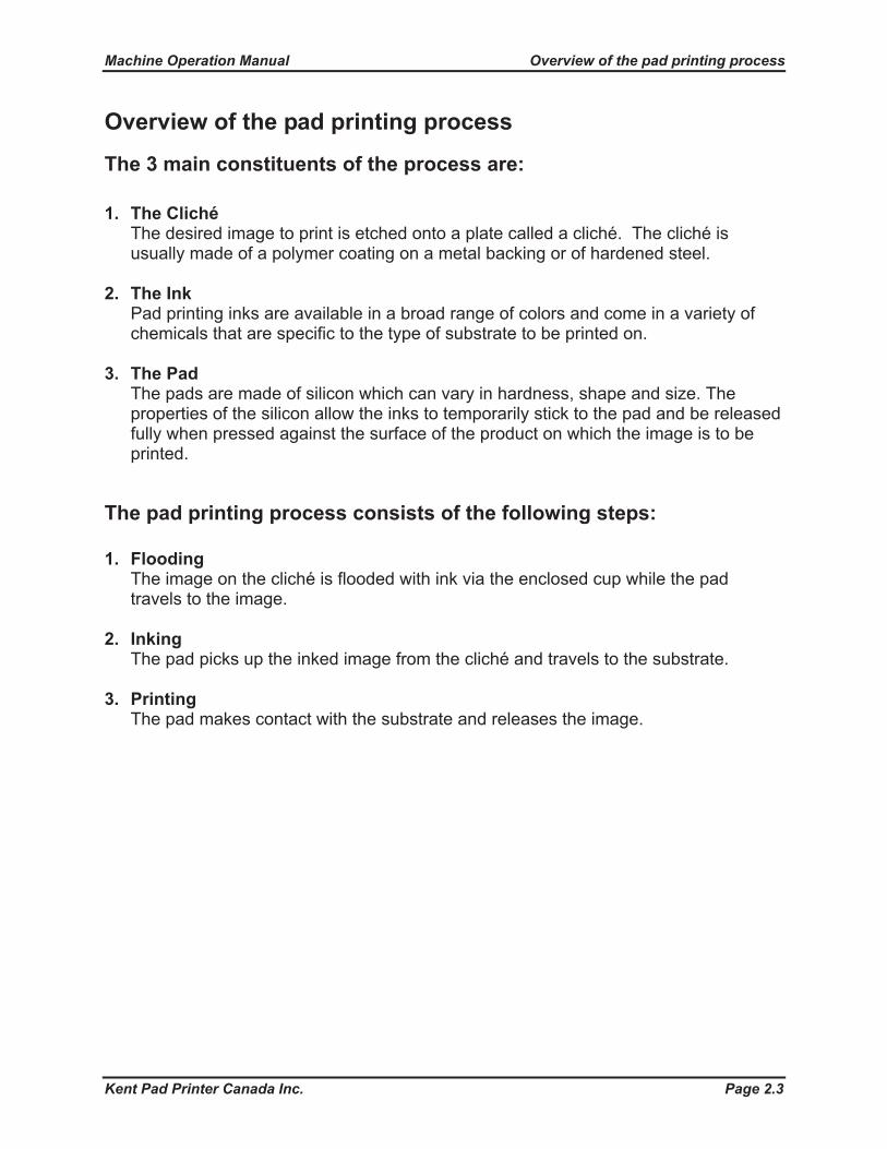
Die plate and ink cup installation
1. Push the doctor blade bar manually completely to the back then unlock and raise the swing arm of ink cup holder.
2. Place thin plate with image facing down over top of cup’s ring side.
3. Turn ink cup setup unit upside down and slide over plate.

Machine Operation Manual Ink cup setup
Kent Pad Printer Canada Inc. Page 5.3
4. Remove ink cup’s lid and pour ink up to 80% full.
5. Screw back lid and loosen bleeding screw knob as to permit air to escape from cup.
6. Fit registration pin with pin hole at the back of platform (right hand side).

Machine Operation Manual Ink cup setup
Kent Pad Printer Canada Inc. Page 5.4
7. Remove unit
8. Fit registration pin with pin hole at the front platform (left hand side).
9. Push cup inside and against the back edge of holder then pull the swing arms down. Lock holder.
10. Repeat steps above to install other plates/cups.

Machine Operation Manual Ink cup setup
Kent Pad Printer Canada Inc. Page 5.5
Ink cup holder adjustmentAdjust the nylon pads of ink cup holder to allow cup to rotate when moving in-out.
Using an Allen key, move the left screw until left nylon pad touches the cup. Then, move the right screw to leave a small gap between right nylon pad and cup.
Die plate & ink cup removal
1. Push the doctor blade bar completely to the back. 2. Unlock and raise the swing arms of ink cup holder. 3. Lift up the front side of thin plate then insert the ink cup setup unit. Push unit forward
against the registration pin at the back. 4. Slide cup forward inside the ink cup setup unit. Tighten the bleeding screw knob. 5. Dislodge the back side of plate then remove the ink cup setup unit carrying the plate
and cup from platform. 6. Turn the ink cup setup unit upside down and remove plate with cup. 7. Carefully, slide the cup out from the side of plate. 8. Clean plate and ring of ink cup with thinner and cover cup with protective plate. 9. Apply grease to the surface of plate and store in a plastic bag to prevent oxidation.
Left/rightscrews
Left/rightnylon pads
Touches Gap

Machine Operation Manual Control Sequence
Kent Pad Printer Canada Inc. Page 6.1
Control Sequence
Main features
2
1
1. Touch screen control panelPress to setup printing jobs
2. Panic switchPress to cut off machine main power and air supply in the event of an emergency
3. +/- Rocker switch Press to set printing parameters
4. Foot switchPress to activates one cycle printing mode or to stop printer in any modes.
5. Safety side guardsOpen side guards to access inner parts of machine.
4
5
3
Machine Operation Manual Control Sequence
Kent Pad Printer Canada Inc. Page 6.2
Control Sequence
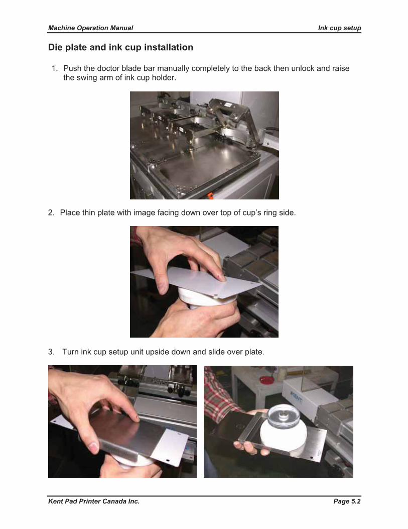
Turning your machine ON
1. Release the panic switch (turn clockwise and pull) then press the power switch at the back to turn your printer on.
Display shows:
Then:
2. If you want to retrieve default’s machine parameters, press “DEFAULT” now. A new page will appear. Press “DEFAULT” again then “EXIT” to return to the entry page.
Press “start “.
Display shows:
Pad shuttle moves to home position and the MANUAL mode screen appears:
DEFAULT
Machine Operation Manual Control Sequence
Kent Pad Printer Canada Inc. Page 6.3
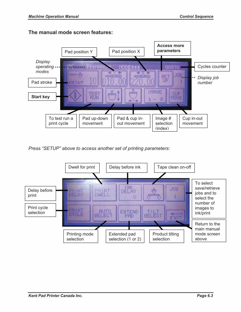
The manual mode screen features:
Press “SETUP” above to access another set of printing parameters:
Pad stroke
Start key
To test run a print cycle
Pad up-down movement
Pad & cup in-out movement
Delay before print
Print cycle selection
Dwell for print Delay before ink Tape clean on-off
Printing mode selection
Pad position Y
Cup in-out movement
Pad position X
Image # selection (index)
Extended pad selection (1 or 2)
Product tilting selection
To select save/retrievejobs and to select the number of images to ink/print
Return to the main manual mode screen above
Display job number
Access more parameters
Cycles counterDisplayoperating modes

Machine Operation Manual Control Sequence
Kent Pad Printer Canada Inc. Page 6.4
Setting up a new printing job
Selecting the number of images to ink/print 1. From the manual mode screen, press “SETUP” then “JOB #”. 2. Press “NO. OF IMAGE #” key repeatedly to select a number of images to ink/print (1
up to 10).
3. Press “EXIT” to return to the main manual mode screen.
Setting product tilting 1. From the manual mode screen,
press “SETUP” then press “TILT SELECT”.
2. Select an image key then input a value on the keypad screen. “1” for tilting or “0” for no tilting.
3. Press “ENT” then “EXIT” when finished.
Setting position and stroke for tape cleaning From the manual mode screen 1. Press “pad in-out” key to stop pad at the front (if not already). 2. Press “IMAGE #” key repeatedly to select image position 0 (for tape clean). 3. Press “pad position X and/or Y” keys then press the +/- toggle switch to position pad
along the x and/or y axis. 4. Press “pad position X and/or Y” keys once again to deselect it. 5. Press “SETUP” key then “EXTEND PAD” key then “CLN #” key. On the keypad
select 1 for pad no. 1 or 2 for pad no. 2.6. Press “pad up-down” key to activate up-down motion of pad. 7. Press ‘pad stroke” key then press the +/- toggle switch to adjust stroke. 8. Deselect ‘pad stroke” and “pad up-down” keys.

Machine Operation Manual Control Sequence
Kent Pad Printer Canada Inc. Page 6.5
Setting position and stroke for inking and printing From the manual mode screen 1. Press the “IMAGE #” key move/select 1st position. 2. Press “pad in-out” key to stop pad at the back for inking. 3. Press “pad position X” key then press the +/- toggle switch to position pad along the
x axis. 4. Press “pad position X” key once again to deselect it. 5. Press “pad position Y” key then press the +/- toggle switch to position pad along the
y axis. 6. Press “pad position Y” key once again to deselect it. 7. Press “pad up-down” key to activate up-down motion of pad. 8. Press ‘pad stroke” key then press the +/- toggle switch to adjust stroke.9. Deselect ‘pad stroke” and “pad up-down” keys. 10. Press “pad in-out” key to stop pad at the front for printing. 11. Repeat steps 3-9 above. 12. Press “TEST RUN” to activate one ink-print cycle. 13. Press “IMAGE #” key again to select another position and repeat steps above.

Machine Operation Manual Control Sequence
Kent Pad Printer Canada Inc. Page 6.6
Setting PRINT DELAY -- Delay before print Pad pauses above object for the time selected before moving down for printing.
1. From the manual mode screen, press “SETUP” then press “PRINT DELAY”. 2. Select an image key then input a value on the key pad screen. Values available: 0-
50 (0-5 sec). 3. Press “ENT” then “EXIT” when finished.
Setting PRINT DWELL -- Dwell at print Pad dwells on the product for the time selected allowing more time to release image.
4. From the manual mode screen, press “SETUP” then press “PRINT DWELL”. 5. Select an image key then input a value on the key pad screen. Values available: 0-
50 (0-5 sec). 6. Press “ENT” then “EXIT” when finished.
Setting INK DELAY -- Delay before ink Pad pauses above image on plate for the time selected before moving down for inking.Note: only one delay for all inking positions is available.
1. From the manual mode screen, press “SETUP” then press “INK DELAY”. 2. Press +/- rocker switch to increase/decrease value. Values available: 0-50 (0-5 sec). 3. Deselect “INK DELAY” when finished.

Machine Operation Manual Control Sequence
Kent Pad Printer Canada Inc. Page 6.7
Setting TAPE CLEAN -- Tape clean ON-FF Pad is tape cleaned before inking.
1. From the manual mode screen, press “SETUP” then press “TAPE CLEAN”. 2. Select an image key then input 1 (ON) or 0 (OFF) on the keypad screen. 3. Press “ENT” then “EXIT” when finished.
Setting PRINT CYCLE -- Print cycle selection
1. From the manual mode screen, press “SETUP” then press “PRINT CYCLE”. 2. Select an image key then input a value (1-4) on the key pad screen.
Values for print cycles available:1 = ink, print 2 = ink, ink, print 3 = ink, print, print 4 = ink, print, ink, print
3. Press “ENT” then “EXIT” when finished.
Setting AUTO SELECT -- Printing mode selection
1. From the manual mode screen, press “SETUP” then press “AUTO SELECT”. 2. Press “1 CYC” key repeatedly to select one cycle mode or “AUTO START” for
automatic mode. 3. Press “AUTO START” key to input an automatic restart or countdown time (auto
mode only).
4. Press “EXIT” when finished.
Machine Operation Manual Control Sequence
Kent Pad Printer Canada Inc. Page 6.8
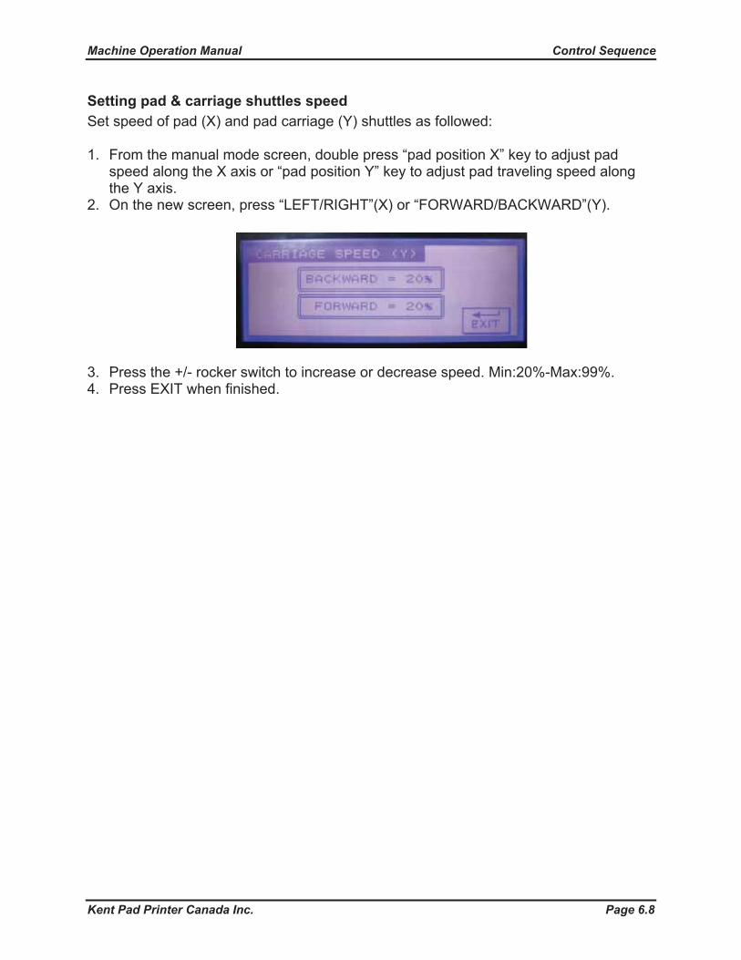
Setting pad & carriage shuttles speed Set speed of pad (X) and pad carriage (Y) shuttles as followed:
1. From the manual mode screen, double press “pad position X” key to adjust pad speed along the X axis or “pad position Y” key to adjust pad traveling speed along the Y axis.
2. On the new screen, press “LEFT/RIGHT”(X) or “FORWARD/BACKWARD”(Y).
3. Press the +/- rocker switch to increase or decrease speed. Min:20%-Max:99%. 4. Press EXIT when finished.

Machine Operation Manual Control Sequence
Kent Pad Printer Canada Inc. Page 6.9
Saving and retrieving jobs
1. From the manual mode screen, press “JOB SEL” to enter the JOB MEMORY screen.
2. Press “SAVE JOB” or “LOAD JOB” key.
3. On the new screen, press the job number.
4. Press the number keys to input a new job number (1-8 available, 8 jobs in total) then press “ENT”.
5. Press OK then EXIT to return to manual mode.
Machine Operation Manual Control Sequence
Kent Pad Printer Canada Inc. Page 6.10
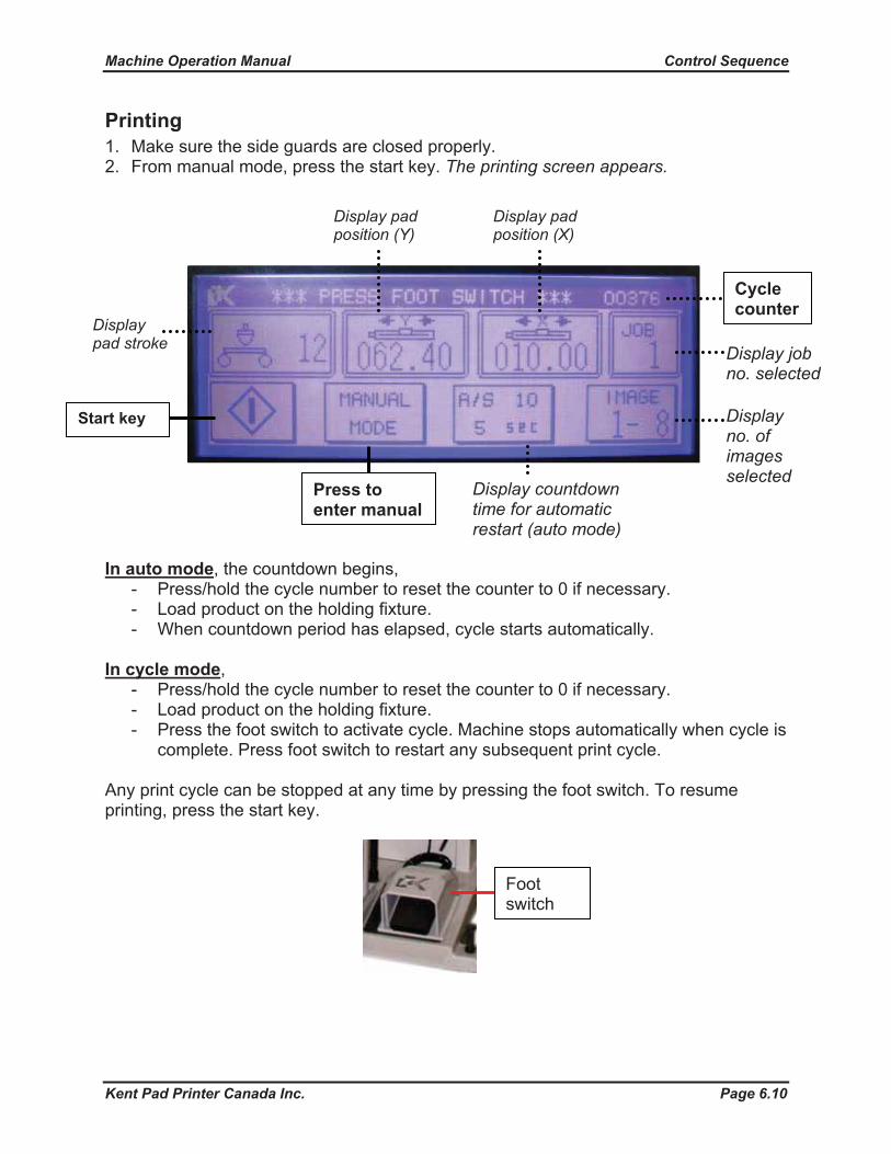
Printing1. Make sure the side guards are closed properly. 2. From manual mode, press the start key. The printing screen appears.
In auto mode, the countdown begins, - Press/hold the cycle number to reset the counter to 0 if necessary. - Load product on the holding fixture. - When countdown period has elapsed, cycle starts automatically.
In cycle mode,- Press/hold the cycle number to reset the counter to 0 if necessary. - Load product on the holding fixture. - Press the foot switch to activate cycle. Machine stops automatically when cycle is
complete. Press foot switch to restart any subsequent print cycle.
Any print cycle can be stopped at any time by pressing the foot switch. To resume printing, press the start key.
Footswitch
Display no. of images selected
Display countdown time for automatic restart (auto mode)
Press to enter manual
Display job no. selected
Displaypad stroke
Start key
Display pad position (X)
Display pad position (Y)
Cycle counter

Machine Operation Manual Control Sequence
Kent Pad Printer Canada Inc. Page 6.11
Stopping your machine Learn the different ways to stop your machine.
Foot switch Press the foot to stop machine at any time in any mode. To resume operations, press the start key.
Safety guards Open the safety side guards to access inner parts of machine for setup and adjustments. Machine will come to a stop. To resume operations, close guards and press the start key.
Panic switch In the event of an emergency, press the panic switch to cut off main power and air supply. Wait approx. 5 seconds, then restart machine by releasing the panic switch (turn clockwise).

Machine Operation Manual
Kent Pad Printer Canada Inc. Page
Machine Setup
7.1
Installing and adjusting the pad
X slide
Y slide
X lockingscrew
Y lockingscrew
Pad
1. Loosen Y locking screw and insert pad onto the Y slide.2. Position pad manually along the Y axis then tighten the Y locking screw.3. Loosen Y locking screw.4. Position pad manually along the X axis then tighten the X locking screw.

Machine Operation Manual
Kent Pad Printer Canada Inc. Page
Tape clean installation & adjustment
Empty roll of tape
Full roll of tape
Springtension
knob
Rollerguide
1. Insert an empty roll of tape onto the mount with rotor (RHS).2. Insert a full roll of tape onto the mount without rotor (LHS).3. Run tape over platform, under the middle roller guide and around the other end then stick onto the empty roll. Make sure the sticky side of tape is facing up. 4. Turn the empty roll manually a few turns.5. Adjust tension of tape by turning the spring tension knob.
Machine Setup
7.2

Machine Operation Manual
Kent Pad Printer Canada Inc. Page
Machine SetupWorktable Adjustment:
Y adjustment knob
Z adjustment hand wheel
Z locking handles (x2)
Adjust the worktable platform to fi nd suitable printing position.
Y locking handles (x2)
Z locking handle
Y Adjustment:1. Release Y locking handles (x2).2. Turn Y adjustment knob to adjust the Y position.3. Tighten Y locking handles (x2).
Z (Up/Down) Adjustment:1. Release Z locking handles (x3).2. Turn the Z adj. handwheel to adjust up/down position.3. Tighten Z locking handles (x3).
7.3
Machine Operation Manual
Kent Pad Printer Canada Inc. Page
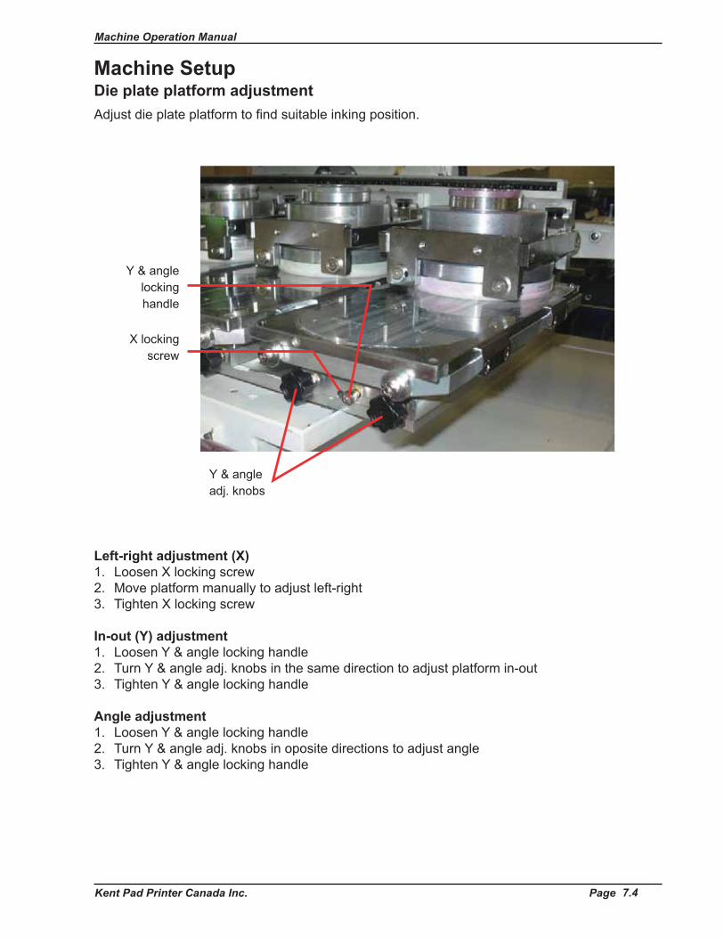
Die plate platform adjustmentAdjust die plate platform to fi nd suitable inking position.
Left-right adjustment (X)1. Loosen X locking screw2. Move platform manually to adjust left-right3. Tighten X locking screw
In-out (Y) adjustment1. Loosen Y & angle locking handle2. Turn Y & angle adj. knobs in the same direction to adjust platform in-out3. Tighten Y & angle locking handle
Angle adjustment1. Loosen Y & angle locking handle2. Turn Y & angle adj. knobs in oposite directions to adjust angle3. Tighten Y & angle locking handle
Y & angle adj. knobs
Y & angle lockinghandle
X locking screw
7.4
Machine Setup
Machine Operation Manual
Kent Pad Printer Canada Inc. Page
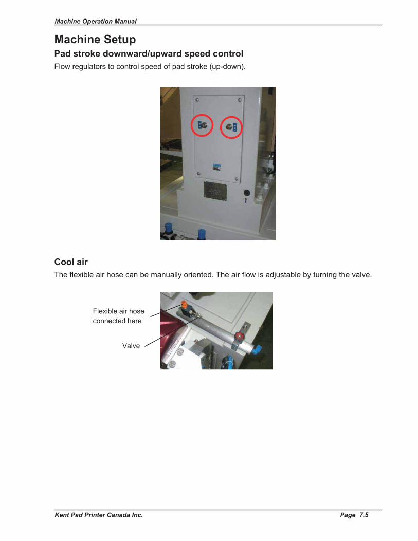
Pad stroke downward/upward speed controlFlow regulators to control speed of pad stroke (up-down).
Cool airThe fl exible air hose can be manually oriented. The air fl ow is adjustable by turning the valve.
7.5
Machine Setup
Valve
Flexible air hose connected here
Machine Operation Manual
Kent Pad Printer Canada Inc. Page
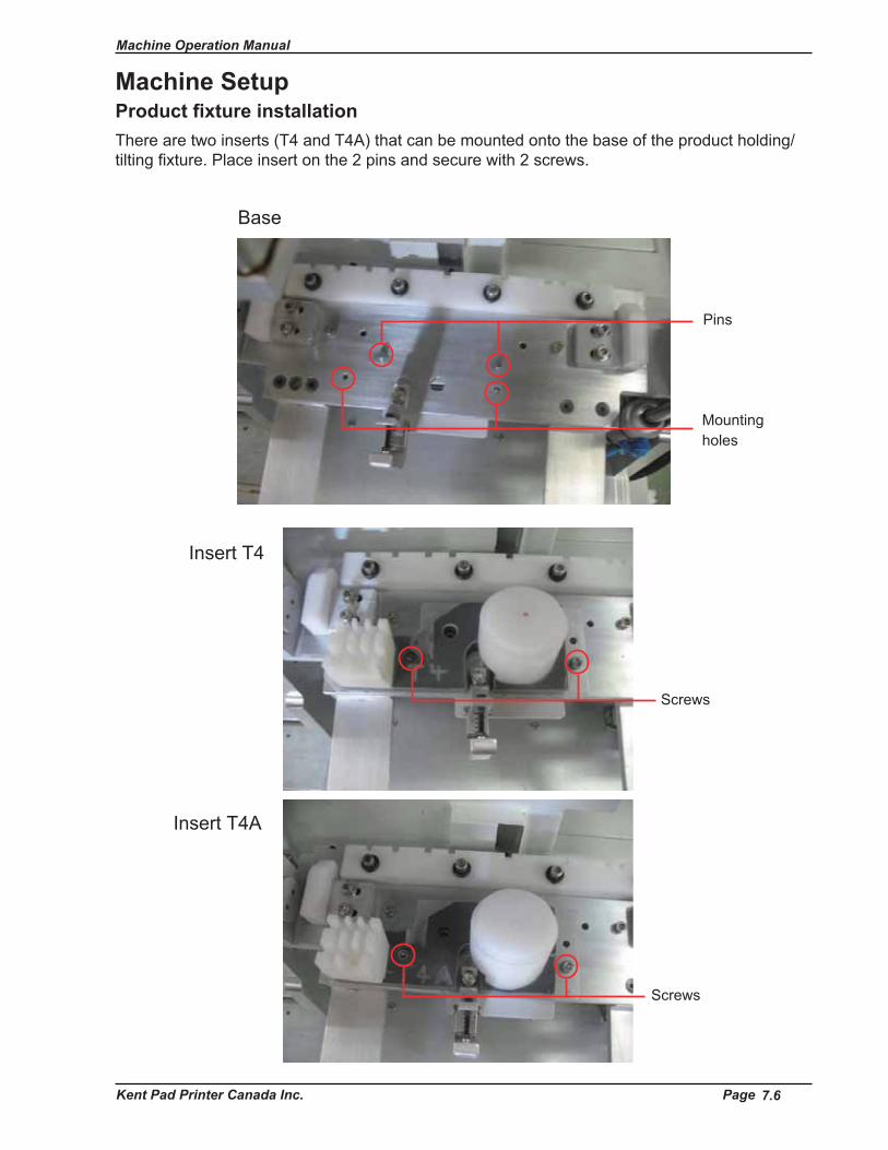
Product fixture installationThere are two inserts (T4 and T4A) that can be mounted onto the base of the product holding/tilting fi xture. Place insert on the 2 pins and secure with 2 screws.
Machine Setup
Pins
Base
Insert T4
Insert T4A
Mountingholes
Screws
Screws
7.6

Machine Operation Manual
Kent Pad Printer Canada Inc. Page
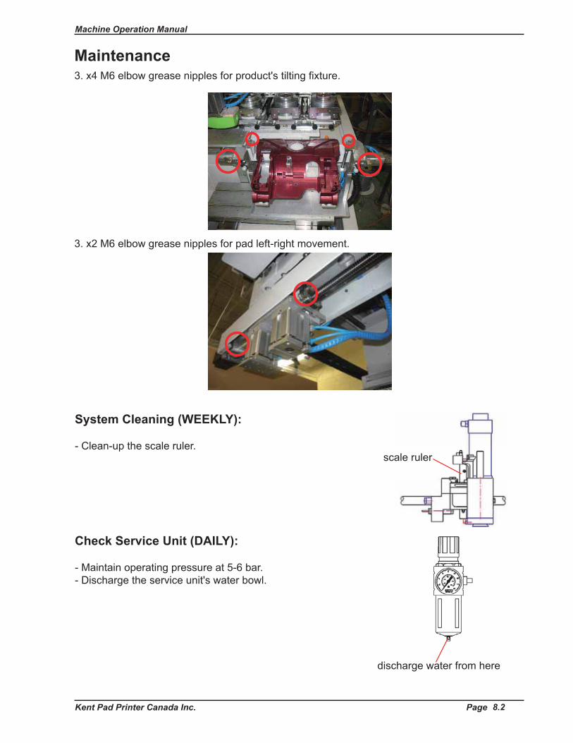
MaintenanceMachine will run longer and perform better when it's maintained regularly. Follow these simple steps:Lubrication (WEEKLY):Please lubricate the following parts circled in red:
1. x4 M6 elbow grease nipples for pad stroke (up-down).
2. x3 M6 elbow grease nipples for pad carriage (in-out).
3. x2 M6 elbow grease nipples for ind. stroke.
2 more on opposite side
8.1

Machine Operation Manual
Kent Pad Printer Canada Inc. Page
Maintenance
Check Service Unit (DAILY):
- Maintain operating pressure at 5-6 bar. - Discharge the service unit's water bowl.
discharge water from here
System Cleaning (WEEKLY):
- Clean-up the scale ruler. scale ruler
3. x4 M6 elbow grease nipples for product's tilting fi xture.
3. x2 M6 elbow grease nipples for pad left-right movement.
8.2
Machine Operation Manual
Kent Pad Printer Canada Inc. Page
MaintenanceHOW TO KEEP YOUR PAD PRINTER IN GOOD CONDITION
Section A: Pneumatic system.Air must be clear of water and oil.
Problem:Service unit contains excessive amount of water and oil resulting in:- Water fl owing into cylinders and valves.- Printer inoperable.- Damaged rubber rings of solenoid valves, causing the printer to worked improperly.
Solution:a. Install a fi lter/dryer upstream at back of air compressor to extract moisture and other contaminants.b. To keep 4.5 bars air pressure or above - single color printing setup. To keep 6.0 bars air pressure or above - double and 4 color set up or above.
Section B: Mechanical checking.Regular machine checking and lubrication of easy-rusting parts.
Example: Shafts, lead screws, doctor blade mounting parts, etc...- Check that screws aren't becoming loose from machine vibrations. Tighten if necessary.- Check that no ink has been spilled outside the ink cup or ink tray. Clean if necessary.- When not operating printer for an extended period of time: Cover the whole printer well with a sealed plastic bag. Apply anti-rust oil onto easy-rust areas. Ensure the power switch is turned off.
Section C: Electricity. Input power should be kept at (depends on model): - AC 110V+/-10% or 220V+/-10%. - If the voltage differential is too big, a voltage regulator is needed.
Example:- If the voltage is below the range, printer will not work properly.- If the voltage is over the range, components of printer will overheat and printer will eventually sease to operate.
Section D: Maintaining the silicone pad.- On average, pad can be stored for up to 6 months. (The higher the room temparature, the shorter the life.)- Pad must be clean. Removed any ink left on pad after each printing job and stored in a cool place.- Pad should never be stored in a plastic bag.
8.3

Machine Operation Manual
Kent Pad Printer Canada Inc. Page
MaintenanceSection E: Daily checking.1. The input voltage should be kept at (depends on model) AC 110V+/-10% or 220V+/-10% and the earth line must be connected properly.
2. Air intake pressure must be no less than 4.5 Bars. If not, printer may malfunction or printing distortion may appear.
3. Right air pressure for doctor blade: a. 1.5 ~ 2.0 Bars for thin steel plate. b. 2.0 Bars for 10mm steel plate. c. For 10mm plate, doctor blade should be replaced if the air pressure is over 3 Bars.
4. Large amount of water deposited in the water regulator bowl: Install an air fi lter/dryer.OR Install a refrigerated air dryer.
5. Smoothness of the air release process in the pneumatic system: Each movement of printer is activated by the pneumatic system. The air is released through silencers attached to solenoid valves. If a silencer is blocked, the related moving part slows down. In this scenario, the silencer should be deposited into lacquer thinner for aprrox. 2 hours for cleaning up and then reinstalled back. If speed not improving, replace the part.
6. After each printing job or at the end of a working day, operators have to handle the printer and all relevant parts carefully to keep them in good condition for the upcoming new jobs.
Open Ink Tray System:- Ink residue must be taken away from the ink tray.- Ink on plate must be cleaned up with thinner and be coated with oil to avoid oxidisation.
Ink Cup System:- Plate must be cleaned with lacquer thinner thoroughly to avoid chemical reaction between the ink and plate.- Ink cup must be covered with cover plate to stop ink inside the cup to be exposed to air.- Ink on plate must be cleaned up with lacquer thinner and coated with oil to avoid oxidisation.
8.4

Machine Operation Manual
Kent Pad Printer Canada Inc. Page
Technical DrawingsSection
Appendix A
Machine Operation Manual
Kent Pad Printer Canada Inc. Page
Sensor Layout
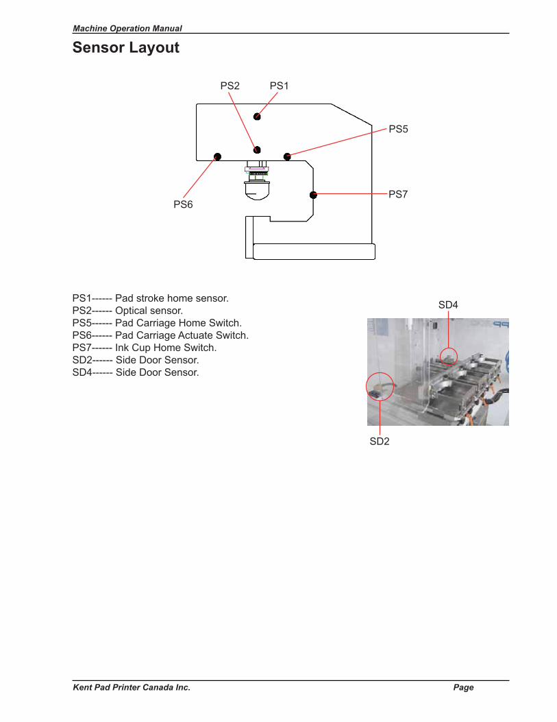
PS1------ Pad stroke home sensor. PS2------ Optical sensor. PS5------ Pad Carriage Home Switch. PS6------ Pad Carriage Actuate Switch. PS7------ Ink Cup Home Switch. SD2------ Side Door Sensor.SD4------ Side Door Sensor.
PS6
PS5
PS1PS2
PS7
SD2
SD4

Machine Operation Manual
Kent Pad Printer Canada Inc. Page
Appendix B
Spare Parts ListSection

Machine Operation Manual
Kent Pad Printer Canada Inc. Page
MaintenanceMachine will run longer and perform better when it's maintained regularly. Follow these simple steps:Lubrication (WEEKLY):Please lubricate the following parts circled in red:
1. x4 M6 elbow grease nipples for pad stroke (up-down).
2. x3 M6 elbow grease nipples for pad carriage (in-out).
3. x2 M6 elbow grease nipples for ind. stroke.
2 more on opposite side
8.1
Machine Operation Manual
Kent Pad Printer Canada Inc. Page
Maintenance
Check Service Unit (DAILY):
- Maintain operating pressure at 5-6 bar. - Discharge the service unit's water bowl.
discharge water from here
System Cleaning (WEEKLY):
- Clean-up the scale ruler. scale ruler
3. x4 M6 elbow grease nipples for product's tilting fi xture.
3. x2 M6 elbow grease nipples for pad left-right movement.
8.2

Machine Operation Manual
Kent Pad Printer Canada Inc. Page
MaintenanceHOW TO KEEP YOUR PAD PRINTER IN GOOD CONDITION
Section A: Pneumatic system.Air must be clear of water and oil.
Problem:Service unit contains excessive amount of water and oil resulting in:- Water fl owing into cylinders and valves.- Printer inoperable.- Damaged rubber rings of solenoid valves, causing the printer to worked improperly.
Solution:a. Install a fi lter/dryer upstream at back of air compressor to extract moisture and other contaminants.b. To keep 4.5 bars air pressure or above - single color printing setup. To keep 6.0 bars air pressure or above - double and 4 color set up or above.
Section B: Mechanical checking.Regular machine checking and lubrication of easy-rusting parts.
Example: Shafts, lead screws, doctor blade mounting parts, etc...- Check that screws aren't becoming loose from machine vibrations. Tighten if necessary.- Check that no ink has been spilled outside the ink cup or ink tray. Clean if necessary.- When not operating printer for an extended period of time: Cover the whole printer well with a sealed plastic bag. Apply anti-rust oil onto easy-rust areas. Ensure the power switch is turned off.
Section C: Electricity. Input power should be kept at (depends on model): - AC 110V+/-10% or 220V+/-10%. - If the voltage differential is too big, a voltage regulator is needed.
Example:- If the voltage is below the range, printer will not work properly.- If the voltage is over the range, components of printer will overheat and printer will eventually sease to operate.
Section D: Maintaining the silicone pad.- On average, pad can be stored for up to 6 months. (The higher the room temparature, the shorter the life.)- Pad must be clean. Removed any ink left on pad after each printing job and stored in a cool place.- Pad should never be stored in a plastic bag.
8.3

Machine Operation Manual
Kent Pad Printer Canada Inc. Page
MaintenanceSection E: Daily checking.1. The input voltage should be kept at (depends on model) AC 110V+/-10% or 220V+/-10% and the earth line must be connected properly.
2. Air intake pressure must be no less than 4.5 Bars. If not, printer may malfunction or printing distortion may appear.
3. Right air pressure for doctor blade: a. 1.5 ~ 2.0 Bars for thin steel plate. b. 2.0 Bars for 10mm steel plate. c. For 10mm plate, doctor blade should be replaced if the air pressure is over 3 Bars.
4. Large amount of water deposited in the water regulator bowl: Install an air fi lter/dryer.OR Install a refrigerated air dryer.
5. Smoothness of the air release process in the pneumatic system: Each movement of printer is activated by the pneumatic system. The air is released through silencers attached to solenoid valves. If a silencer is blocked, the related moving part slows down. In this scenario, the silencer should be deposited into lacquer thinner for aprrox. 2 hours for cleaning up and then reinstalled back. If speed not improving, replace the part.
6. After each printing job or at the end of a working day, operators have to handle the printer and all relevant parts carefully to keep them in good condition for the upcoming new jobs.
Open Ink Tray System:- Ink residue must be taken away from the ink tray.- Ink on plate must be cleaned up with thinner and be coated with oil to avoid oxidisation.
Ink Cup System:- Plate must be cleaned with lacquer thinner thoroughly to avoid chemical reaction between the ink and plate.- Ink cup must be covered with cover plate to stop ink inside the cup to be exposed to air.- Ink on plate must be cleaned up with lacquer thinner and coated with oil to avoid oxidisation.
8.4
Machine Operation Manual Appendix A
Kent Pad Printer Canada Inc. Appendix A-1
Appendix A
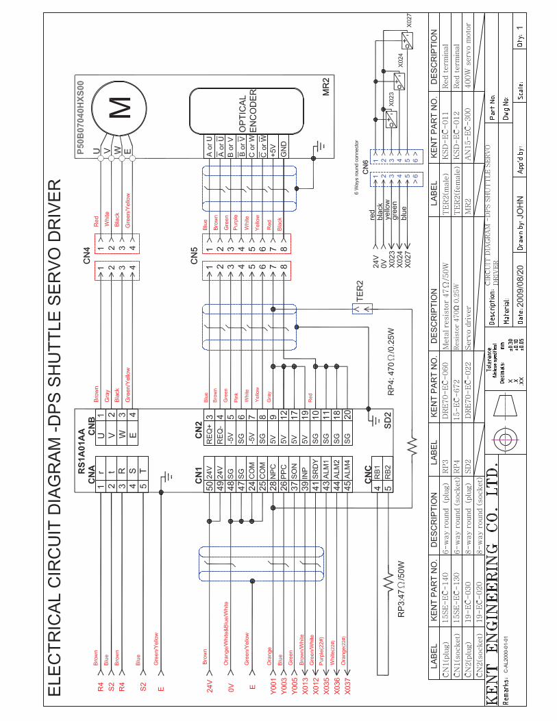
CIRCUITS/DIAGRAMS


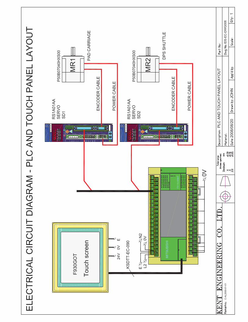

IO allocations FX1N-60MT Display : F930Got-BWd-CPad shuttle Servo Motor : P50B07040HXS1j , 400W
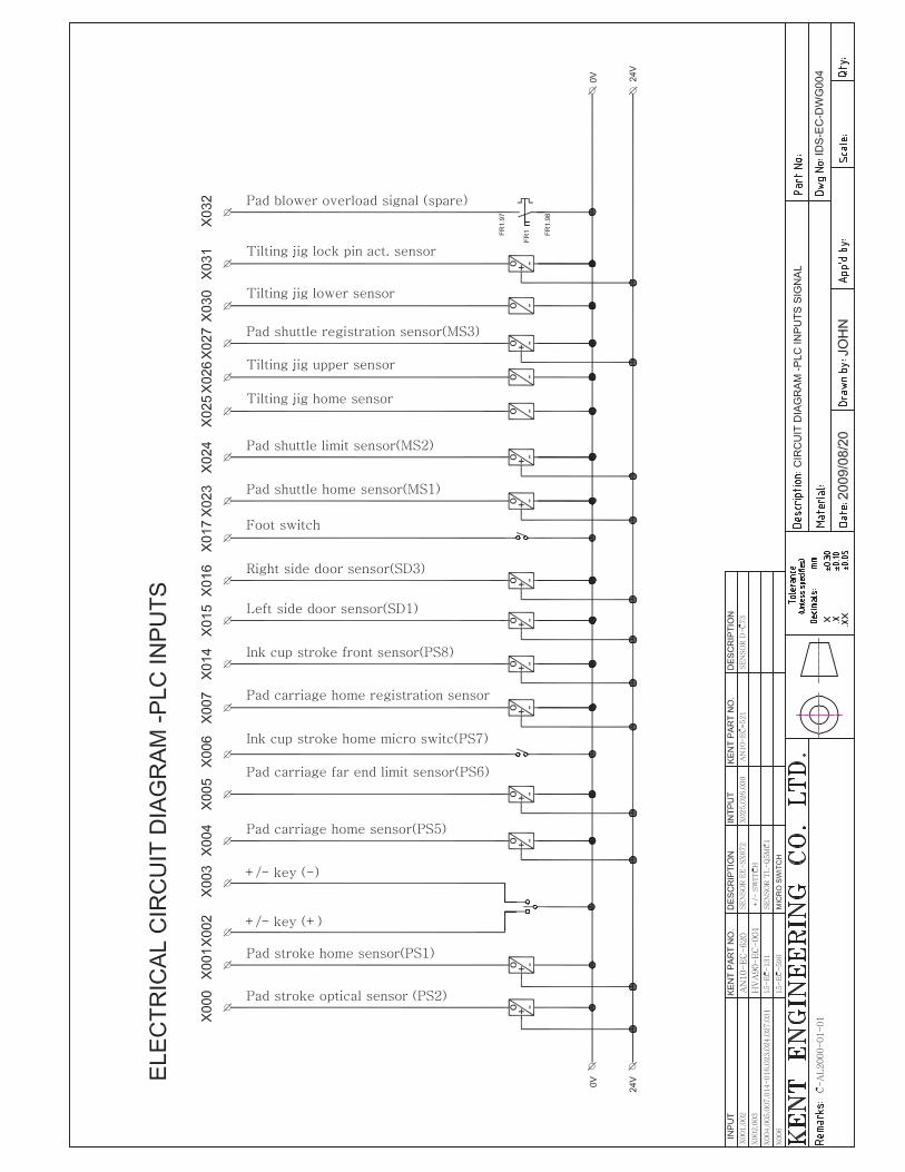
Input Description Output Description X000 Optical sensor Y000 Carriage pulse X001 Pad stroke home sensor Y001 Pad shuttle pulse X002 + switch Y002 Carriage direction X003 - switch Y003 Pad shuttle direction X004 Carriage rear limit switch Y004 Carriage shuttle servo on X005 Carriage front home switch Y005 Pad shuttle servo on X006 Ink cup rear home switch Y006 Spare (index A ) X007 Carriage registration sensor Y007 Spare ( index B ) X010 Carriage servo ready Y010 Buzzer X011 Carriage servo end complete Y011 Main air solenoid X012 Pad shuttle servo ready Y012 Ink cup solenoid X013 Pad shuttle servo end complete Y013 tape solenoid X014 Ink cup front switch Y014 Pad U/D solenoid X015 right side door switch Y015 Dwell solenoid X016 left side door switch Y016 Spare ( Vacuum ) X017 Foot switch Y017 Spare ( lock ) X020 Conf.1(pin5) Y020 Spare (Blower On/Off ) X021 Conf.2(pin4) Y021 Tilt ( jig ) X022 Conf.3(pin3) Y022 Pin ( jig ) X023 Pad shuttle home MS1 Y023 Extend pad 1 X024 Pad shuttle limit MS2 Y024 Extend pad 2 X025 Tilt middle sensor Y025 Spare ( extend pad 3 ) X026 Tilt upper sensor Y026 Spare ( extend pad 4 ) X027 Pad shuttle registration sensor MS3 Y027 Spare ( extend pad 5 ) X030 Tilt lower sensor X031 Pin act. sensor X032 Spare (Blower overload sensor) X033 Spare X034 Spare (Vacuum sensor ) X035—X037 DPS Error code (Spare ) X040 Spare (Lubricate sensor) X041 – X043 Carriage Error code ( Spare )
Pad shuttle: 500 mm, home search to left side (motor at left side) (face to machine) Carriage shuttle: 350 mm, home search to front (motor at rear) (face to machine) Pad shuttle position: 5-450 mm. Carriage shuttle position: 5-310mm Delay before ink: 0 to 5 sec. - Delay before print 0 to 5 sec. - Dwell at print 0 to 5 sec. Ink stroke: 8 mm to 108 mm - Print /clean stroke: 8mm to 150mm Optical: 1mm scale - Job save: 1 to 8 - Auto start: 0 to 30 sec. - No. of tape turn: 0 to 4


Machine Operation Manual
Kent Pad Printer Canada Inc. Page
Sensor Layout
PS1------ Pad stroke home sensor. PS2------ Optical sensor. PS5------ Pad Carriage Home Switch. PS6------ Pad Carriage Actuate Switch. PS7------ Ink Cup Home Switch. SD2------ Side Door Sensor.SD4------ Side Door Sensor.
PS6
PS5
PS1PS2
PS7
SD2
SD4

Machine Operation Manual Appendix B
Kent Pad Printer Canada Inc. Appendix B-1
Appendix B
SPARE PARTS LIST
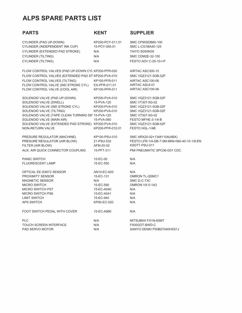
ALPS SPARE PARTS LIST
PARTS KENT SUPPLIER
CYLINDER (PAD UP-DOWN) KP200-PCY-011.01 SMC CP95SDB80-100CYLINDER (INDEPENDENT INK CUP) 15-PCY-050.01 SMC L-CG1BA40-125CYLINDER (EXTENDED PAD STROKE) N/A TAIYO SD50N30CYLINDER (TILTING) N/A SMC CDM2E-32-100CYLINDER (TILTING) N/A FESTO ADV C-25-10-I-P
FLOW CONTROL VALVES (PAD UP-DOWN CYL KP200-PFR-020 AIRTAC ASC300-10FLOW CONTROL VALVES (EXTENDED PAD ST KP200-PVA-010 SMC VQZ3121-5GB-02FFLOW CONTROL VALVES (TILTING) KP100-PFR-011 AIRTAC ASC100-06FLOW CONTROL VALVE (IND STROKE CYL) EX-PFR-011.01 AIRTAC ASL6-01FLOW CONTROL VALVE (COOL AIR) KP100-PFR-011 AIRTAC ASC100-06
SOLENOID VALVE (PAD UP-DOWN) KP200-PVA-010 SMC VQZ3121-5GB-02FSOLENOID VALVE (DWELL) 15-PVA-120 SMC VT307-5G-02SOLENOID VALVE (IND STROKE CYL) KP200-PVA-010 SMC VQZ3121-5GB-02FSOLENOID VALVE (TILTING) KP200-PVA-010 SMC VQZ3121-5GB-02FSOLENOID VALVE (TAPE CLEAN TURNING DEV15-PVA-120 SMC VT307-5G-02SOLENOID VALVE (MAIN AIR) 15-PVA-060 FESTO MFHE-3-1/4-BSOLENOID VALVE (EXTENDED PAD STROKE) KP200-PVA-010 SMC VQZ3121-5GB-02FNON-RETURN VALVE KP200-PFR-010.01 FESTO HGL-1/4B
PRESURE REGULATOR (MACHINE) KP100-PSU-010 SMC ARX20-02+1348110A(ABX)PRESURE REGULATOR (AIR BLOW) 21-PSU-032 FESTO LFR-1/4-DB-7-5M-MINI+MA-40-10-1/8-ENFILTER (AIR BLOW) AFM-20-02 KSDTT-PSU-011AUX. AIR QUICK CONNECTOR COUPLING 15-PFT-311 PMI PNEUMATIC SPC06-G01 CDC
PANIC SWITCH 15-EC-00 N/AFLUORESCENT LAMP 15-EC-550 N/A
OPTICAL EE-SX672 SENSOR AN10-EC-620 N/APROXIMITY SENSOR 15-EC-131 OMRON TL-Q5MC1MAGNETIC SENSOR N/A SMC D-C-73CMICRO SWITCH 15-EC-590 OMRON VX-5-1A3MICRO SWITCH PS7 15-EC-A040 N/AMICRO SWITCH PS6 15-EC-A041 N/ALIMIT SWITCH 15-EC-940 N/AAPS SWITCH KP90-EC-020 N/A
FOOT SWITCH PEDAL WITH COVER 15-EC-A990 N/A
PLC N/A MITSUBIHI FX1N-60MTTOUCH SCREEN INTERFACE N/A F930GOT-BWD-CPAD SERVO MOTOR N/A SANYO DENKI P50B07040HXS1J


![Tru Laser [Basic Machine Operation & PM]](https://static.fdocuments.us/doc/165x107/55cf96ef550346d0338ebed1/tru-laser-basic-machine-operation-pm.jpg)