Alpine CT4 Suspension Installation Guide - teraflex.com · 1 Revision A 999274 Alpine CT4...
20
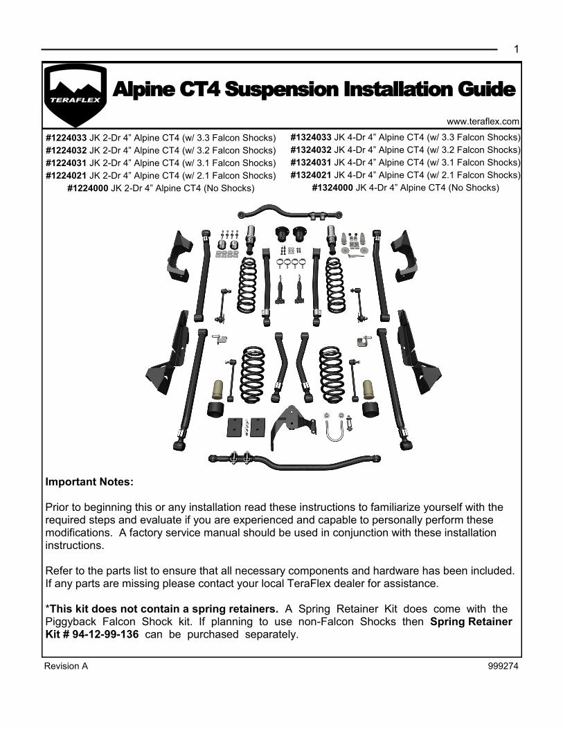
1 Revision A 999274 www.teraflex.com Alpine CT4 Suspension Installation Guide Important Notes: Prior to beginning this or any installation read these instructions to familiarize yourself with the required steps and evaluate if you are experienced and capable to personally perform these modifications. A factory service manual should be used in conjunction with these installation instructions. Refer to the parts list to ensure that all necessary components and hardware has been included. If any parts are missing please contact your local TeraFlex dealer for assistance. *This kit does not contain a spring retainers. A Spring Retainer Kit does come with the Piggyback Falcon Shock kit. If planning to use non-Falcon Shocks then Spring Retainer Kit # 94-12-99-136 can be purchased separately. #1224033 JK 2-Dr 4” Alpine CT4 (w/ 3.3 Falcon Shocks) #1224032 JK 2-Dr 4” Alpine CT4 (w/ 3.2 Falcon Shocks) #1224031 JK 2-Dr 4” Alpine CT4 (w/ 3.1 Falcon Shocks) #1224021 JK 2-Dr 4” Alpine CT4 (w/ 2.1 Falcon Shocks) #1224000 JK 2-Dr 4” Alpine CT4 (No Shocks) #1324033 JK 4-Dr 4” Alpine CT4 (w/ 3.3 Falcon Shocks) #1324032 JK 4-Dr 4” Alpine CT4 (w/ 3.2 Falcon Shocks) #1324031 JK 4-Dr 4” Alpine CT4 (w/ 3.1 Falcon Shocks) #1324021 JK 4-Dr 4” Alpine CT4 (w/ 2.1 Falcon Shocks) #1324000 JK 4-Dr 4” Alpine CT4 (No Shocks)
Transcript of Alpine CT4 Suspension Installation Guide - teraflex.com · 1 Revision A 999274 Alpine CT4...
1
Revision A 999274
www.teraflex.com
Alpine CT4 Suspension Installation Guide
Important Notes: Prior to beginning this or any installation read these instructions to familiarize yourself with the required steps and evaluate if you are experienced and capable to personally perform these modifications. A factory service manual should be used in conjunction with these installation instructions. Refer to the parts list to ensure that all necessary components and hardware has been included. If any parts are missing please contact your local TeraFlex dealer for assistance. *This kit does not contain a spring retainers. A Spring Retainer Kit does come with the Piggyback Falcon Shock kit. If planning to use non-Falcon Shocks then Spring Retainer Kit # 94-12-99-136 can be purchased separately.
#1224033 JK 2-Dr 4” Alpine CT4 (w/ 3.3 Falcon Shocks)
#1224032 JK 2-Dr 4” Alpine CT4 (w/ 3.2 Falcon Shocks)
#1224031 JK 2-Dr 4” Alpine CT4 (w/ 3.1 Falcon Shocks)
#1224021 JK 2-Dr 4” Alpine CT4 (w/ 2.1 Falcon Shocks)
#1224000 JK 2-Dr 4” Alpine CT4 (No Shocks)
#1324033 JK 4-Dr 4” Alpine CT4 (w/ 3.3 Falcon Shocks)
#1324032 JK 4-Dr 4” Alpine CT4 (w/ 3.2 Falcon Shocks)
#1324031 JK 4-Dr 4” Alpine CT4 (w/ 3.1 Falcon Shocks)
#1324021 JK 4-Dr 4” Alpine CT4 (w/ 2.1 Falcon Shocks)
#1324000 JK 4-Dr 4” Alpine CT4 (No Shocks)

www.teraflex.com
2
Revision A 999274
Item ID JK 2 Door Alpine CT4 Suspension System Kit Qty
1152482 JK 2 Door 4" Lift Kit Spring Box w/out Bumpstop Extensions 1
1315001 JK Alpine Lower Long Arm Kit 1
1315002 JK Alpine Upper Long Arm Kit 1
1467265 JK Rear Upper Speedbump Bumpstop Cup Extension KIT 1
1753418 JK Front Forged Monster Trackbar Kit 1
1754418 JK Rear Forged Monster Trackbar Kit 1
1944730 JK 3" Front SpeedBump 1/4" & 3/4" Adjustment Spacer Kit 1
1953750 JK 3" Front SpeedBump Kit (Pair) 1
1954615 JK SpeedBump 2.25"-3" Rear Lower Bumpstop Subassembly 1
1957000 JK Long FlexArm Bracket Kit for Adjustable FlexArms 1
1992014 JK Rear Upper Microcellular Bumpstop Kit (Pair) 1
2610000 JK Exhaust Spacer Kit for 2012+ JKs with the 3.6 Pentastar 1
4946810 JK Front SpeedBump Spring Bucket Jounce Tube Brace Kit 1
Tools Needed
• Jack • Car Lift (or Jack Stands) • MIG Welder • Ratchet - 1/4” and 1/2” • 1/4” Drive Socket Set - 1/4”, 5/16”, 10mm, 7/16” • 1/2” Drive Swivel/Wobbly Sockets - 18mm,
21mm, 3/4” • 1/2” Drive Socket Set - 18mm, 21mm, 3/4” • 1/2” Extension - 12” Long • Allen Wrench - 3/16”, 5mm • End Wrench Set - 7/16”, 1/2”, 9/16”, 1-1/8”,
13mm, 15mm, 16mm, 18mm, 19mm, 21mm • Drill
• Drill Bits - 1/8”, 1/4”, 3/8”, 1/2” - or step drill bit • Reciprocating Saw and Bi-metal Blade • Wire Cutters • Locking Plyers • Heel Pry Bar • Hammer • Chisel • Measuring Tape • Blue Loctite • FT - LBS Torque Wrench • Safety Glasses • Recommended: Transmission Jack, Air Gun,
Plasma Cutter, Car Lift
Item ID JK 4 Door Alpine CT4 Suspension System Kit Qty
1151484 JK 4 Door 4" Lift Kit Spring Box w/out Bumpstop Extension 1
1315001 JK Alpine Lower Long Arm Kit 1
1315002 JK Alpine Upper Long Arm Kit 1
1467265 JK Rear Upper Speedbump Bumpstop Cup Extension KIT 1
1753418 JK Front Forged Monster Trackbar Kit 1
1754418 JK Rear Forged Monster Trackbar Kit 1
1944730 JK 3" Front SpeedBump 1/4" & 3/4" Adjustment Spacer Kit 1
1953750 JK 3" Front SpeedBump Kit (Pair) 1
1954615 JK SpeedBump 2.25"-3" Rear Lower Bumpstop Subassembly 1
1957000 JK Long FlexArm Bracket Kit for Adjustable FlexArms 1
1992014 JK Rear Upper Microcellular Bumpstop Kit (Pair) 1
2610000 JK Exhaust Spacer Kit for 2012+ JKs with the 3.6 Pentastar 1
4946810 JK Front SpeedBump Spring Bucket Jounce Tube Brace Kit 1

3 www.teraflex.com
Revision A 999274
1 2
6 5
3
Lift the vehicle
Lift the vehicle and support it by the frame. Remove wheels and support the front axle with jack stands.
4
19mm
wrench
Remove front and rear drivelines. The front driveline will be removed with a 5/16” on the 8 CV bolts and a
15mm on the u-joint flange bolts.
Remove the transfer case skid plate and exhaust skid plate/
cross member using an 18mm.
The exhaust skid plate will not be reused.
Remove the sway bar links, using an 18mm socket and wrench, at the axle, and an 18mm socket and 19mm wrench,
at the sway bar.
The rear driveline use the same 5/16”.
Through the two access holes in the rear flange, use a
punch to free the driveline from the axle. Do not let the axle
hang from the CV joint. The transfer case end will be easier
to remove.
18mm
Remove Brake Calipers from front and rear axles
Remove the caliper with the anchor bracket with a 21mm.
Support the caliper from the frame, do not allow the caliper to
hang from the brake hose. A plastic zip tie works well.
4 www.teraflex.com
Revision A 999274
8
10 9
7
11 12
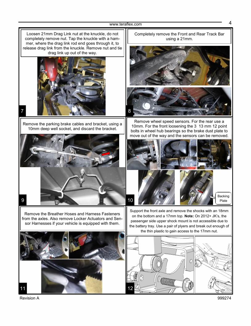
Loosen 21mm Drag Link nut at the knuckle, do not completely remove nut. Tap the knuckle with a ham-mer, where the drag link rod end goes through it, to
release drag link from the knuckle. Remove nut and tie drag link up out of the way.
Completely remove the Front and Rear Track Bar using a 21mm.
Remove the parking brake cables and bracket, using a 10mm deep well socket, and discard the bracket.
Remove wheel speed sensors. For the rear use a 10mm. For the front loosening the 3 13 mm 12 point bolts in wheel hub bearings so the brake dust plate to move out of the way and the sensors can be removed.
Backing
Plate
Remove the Breather Hoses and Harness Fasteners from the axles. Also remove Locker Actuators and Sen-
sor Harnesses if your vehicle is equipped with them.
Support the front axle and remove the shocks with an 18mm
on the bottom and a 17mm top. Note: On 2012+ JK’s, the
passenger side upper shock mount is not accessible due to
the battery tray. Use a pair of plyers and break out enough of
the thin plastic to gain access to the 17mm nut.

5 www.teraflex.com
Revision A 999274
Lower the axle and remove the front springs. Be sure to
check for any lines that may have been missed earlier
to avoid damaging them. Set front axle in a safe place.
13 14
15 16
17 18
Remove all four front control arms with a 21mm or an
18mm. Keep the hardware.
Support the front axle. Apply penetrating oil. These are
captured nuts and a broken bolt here is a real incon-
venience. Remove the two upper bolts with a 16mm.
Remove the lower nut and bolt with an 18mm.
Remove all four front control arms with a 21mm or an 18mm.
Keep the hardware.
Remove Gas Tank starting with the filler neck with a 6mm.
Use a screwdriver or equivalent to depress the white release
to disconnect the vent line.

6 www.teraflex.com
Revision A 999274
Support transfer case and remove nuts and bolts from the cross member. Leave one of the bolts and swing
cross member out of the way.
19
21
20
22
24 23
Disconnect the supply and return lines by squeezing the blue
tabs. Caution! The supply line may still be under pressure.
Have a rag ready to absorb any fuel leaks.
Be sure to cap/protect any open fuel lines. On most models
the supply and return lines can be snapped together.
Disconnect the EVAP lines that run between the EVAP
system and the fuel tank.
Remove the 8 bolts supporting the tank and slowly lower it.
Beware of fuel/electrical lines that are still connected. Once you
have access, remove the remaining electrical connections.
Remove exhaust starting with four 14mm flange bolts.
Spray exhaust hangers with some silicon spray or pen-
etrating oil. Use a pray bar to pry rubber hangers off
and remove exhaust.

7 www.teraflex.com
Revision A 999274
With this portion of exhaust out of the way reinstall the transfer case cross member with bolts pointing forward.
Remove transfer case support.
Disconnect all four O2 sensor connects, one black and one white on each side. Remove both catalytic con-
verters from the manifolds by removing the 10mm bolts at the top of the flange.
After cutting is complete, grind down all remaining slag and
metal to make a smooth surface for mounting the new
brackets. We suggest using a flapper wheel on a 4” grinder.
Un-clip all wire loom and fuel lines near where you will be
cutting and welding. Tuck them above the frame or where
they will not be damaged. With all control arms removed,
begin cutting and removing the control arm brackets. Take
extra care not to cut into the frame. Pay special attention to
the direction of your flames and sparks as well as any hoses
or wires that could be effected by the heat. Beware of any
brake lines above the upper control arm mount on the drivers
side as well. Avoid long, vertical welds on the frame; this may
lead to cracking and frame failure.
The rear gusset plate locates to a control arm hole in the
frame. This will be welded in place before the rear bracket.
The front brackets index to a hole in the bottom of the frame
and two bolts in the cross-member. Replace the cross-
member bolts with longer, provided bolts. 2010-2011 See
page 9-10 now.
25
27
26
28
30 29

8 www.teraflex.com
Revision A 999274
FRONT OF VEHICLE
Mark where the brackets and gussets will contact the frame.
Clean off any paint within 1” of where welding will occur. A
clean surface is key to a strong, lasting weld.
The rear brackets index around a body mount bracket. Cen-
ter the slot in the bracket around the body mount.
Use C-clamps to eliminate any gaps between the new brack-
ets and the frame. Do several tack welds around the bracket
to keep it from warping as you weld. Minimizing the bracket
gap will make for a much better weld.
Weld the rear frame gussets on first. The rear brackets will
weld to the new gussets. Weld on the rear brackets next.
Install the upper SpeedBump cups. The cup snaps
onto the frame bump stop bells.
(It will take some pressure)
Weld the front brackets. Take some time after welding to
clean these sections and paint to prevent rust.
32
33
35
31
34
36

9 www.teraflex.com
Revision A 999274
Reinstall the fuel tank in the reverse order removed. Don’t
forget any fuel lines, EVAP lines or electrical connections.
Torque strap bolts to 30 ft-lbs.
Position the Speed Bump cup with the longer side of
the slope (the large end of the taper) facing the rear.
The notched cuts index around the factory bump stop
bracket.
Twist and push the new Speedbump bump stops into position. Some silicone spray lubricant will help them
pop into place.
Re-install both catalytic converters from the manifolds. Reconnect all four O2 sensor connects, one black and
one white on each side.
If you are installing this lift on a 2012 or newer Wran-gler, you must install the exhaust spacer kit.
Loosen Y-pipe exhaust clamp bolt and remove indexing
nub from Y-pipe. Separate Y-pipe from the rear section
of the exhaust.
38
39
41
37
40
42
10 www.teraflex.com
Revision A 999274
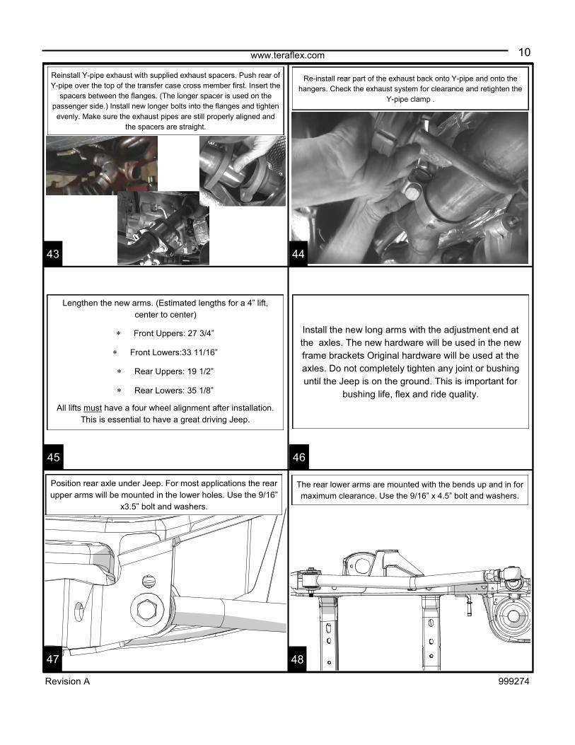
Reinstall Y-pipe exhaust with supplied exhaust spacers. Push rear of
Y-pipe over the top of the transfer case cross member first. Insert the
spacers between the flanges. (The longer spacer is used on the
passenger side.) Install new longer bolts into the flanges and tighten
evenly. Make sure the exhaust pipes are still properly aligned and
the spacers are straight.
Re-install rear part of the exhaust back onto Y-pipe and onto the
hangers. Check the exhaust system for clearance and retighten the
Y-pipe clamp .
Position rear axle under Jeep. For most applications the rear
upper arms will be mounted in the lower holes. Use the 9/16”
x3.5” bolt and washers.
The rear lower arms are mounted with the bends up and in for
maximum clearance. Use the 9/16” x 4.5” bolt and washers.
Install the new long arms with the adjustment end at
the axles. The new hardware will be used in the new
frame brackets Original hardware will be used at the
axles. Do not completely tighten any joint or bushing
until the Jeep is on the ground. This is important for
bushing life, flex and ride quality.
Lengthen the new arms. (Estimated lengths for a 4” lift,
center to center)
Front Uppers: 27 3/4”
Front Lowers:33 11/16”
Rear Uppers: 19 1/2”
Rear Lowers: 35 1/8”
All lifts must have a four wheel alignment after installation.
This is essential to have a great driving Jeep.
44
45
47
43
46
48

11 www.teraflex.com
Revision A 999274
Use the provided sleeve as a spacer and install the
1/2”x3.5” bracket bolt with washers on either side and
a locknut.
Position the TeraFlex bracket so it installs over the factory
bracket and lines up with the lower control arm bolt. Reinstall
the control arm bolt finger tight.
Install the U-bolt around the axle and into the bracket.
Do not torque control arm bolt. Torque: 1/2” bracket
bolt to 75 ft-lbs and U-bolt nuts to 85 ft-lbs.
Install the spring. Raise the axle high enough to reinstall the
shocks. Torque shock bolts to 56 ft-lbs (76 Nm). Remove the factory isolator from the upper spring perch and
install onto the new spring spacer. To aid in installation, apply
grease to the top of the new spacer. Press the isolator and
spacer assembly into the upper spring perch. You can use a
piece of wood as a spacer between spring spacer and the
axle, then raise the axle to press the spacer in.
Grease
Here
Install Rear Monster Trackbar using the upper hole in bracket
and the factory hardware. Do not tighten bolts. If getting
the bolt holes to line up is difficult wait until Jeep in on the
ground, then push the Jeep from the side to line up holes.
50
51
53
49
52
54
12 www.teraflex.com
Revision A 999274
SPRING ISOLATOR
BUMPSTOP
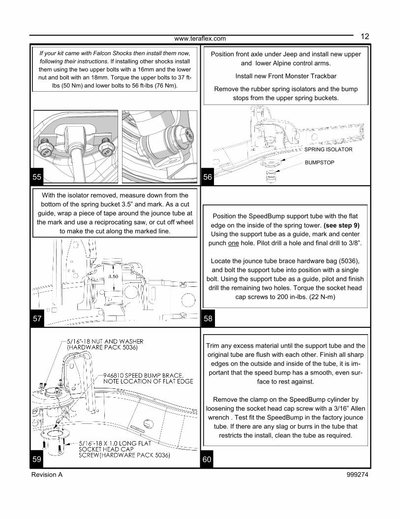
If your kit came with Falcon Shocks then install them now,
following their instructions. If installing other shocks install
them using the two upper bolts with a 16mm and the lower
nut and bolt with an 18mm. Torque the upper bolts to 37 ft-
lbs (50 Nm) and lower bolts to 56 ft-lbs (76 Nm).
Position front axle under Jeep and install new upper
and lower Alpine control arms.
Install new Front Monster Trackbar
Remove the rubber spring isolators and the bump
stops from the upper spring buckets.
Trim any excess material until the support tube and the
original tube are flush with each other. Finish all sharp
edges on the outside and inside of the tube, it is im-
portant that the speed bump has a smooth, even sur-
face to rest against.
Remove the clamp on the SpeedBump cylinder by
loosening the socket head cap screw with a 3/16” Allen
wrench . Test fit the SpeedBump in the factory jounce
tube. If there are any slag or burrs in the tube that
restricts the install, clean the tube as required.
Position the SpeedBump support tube with the flat
edge on the inside of the spring tower. (see step 9)
Using the support tube as a guide, mark and center
punch one hole. Pilot drill a hole and final drill to 3/8”.
Locate the jounce tube brace hardware bag (5036),
and bolt the support tube into position with a single
bolt. Using the support tube as a guide, pilot and finish
drill the remaining two holes. Torque the socket head
cap screws to 200 in-lbs. (22 N-m)
With the isolator removed, measure down from the
bottom of the spring bucket 3.5” and mark. As a cut
guide, wrap a piece of tape around the jounce tube at
the mark and use a reciprocating saw, or cut off wheel
to make the cut along the marked line.
56
57
59
55
58
60

13 www.teraflex.com
Revision A 999274
SPRING ISOLATOR
SPEEDBUMP
SPEEDBUMP CLAMP
SOCKET HEAD CAP SCREW
Coat the lower portion of the SpeedBump with black RTV silicone to help with noise and corrosion. Slide the
bump stop into position.
Apply pressure on the SpeedBump to make sure that it is completely seated and install retainer clamp. Torque to 74.5 in-lbs. (8 N-m) and reinstall the factory isolator.
62
63
65
61
64
66
Drill Out Hole for SpeedBump Pad
Locate the center of the spring pad and drill a 3/8”
hole for the SpeedBump pads.
Front Springs
Install new front springs. Slip the 1.25” Speed-
Bump Pad into the spring.
SpeedBump Pad
Install the supplied 3/8" x 2" Flat Head Allen Bolt
through the SpeedBump Pad with the 3/8” Flanged
Serrated Nut below the spring pad. Use the supplied
wrench to position and hold the nut and tighten the bolt.
Front Shocks
If using Falcon Shocks follow instruction included with them
to install the fronts now. If using other shocks install them
now. Torque the top nut to 20 ft-lbs (27 N-m). Leave lower
bolt lose for the brake line anchor install.
14 www.teraflex.com
Revision A 999274
6mm allen
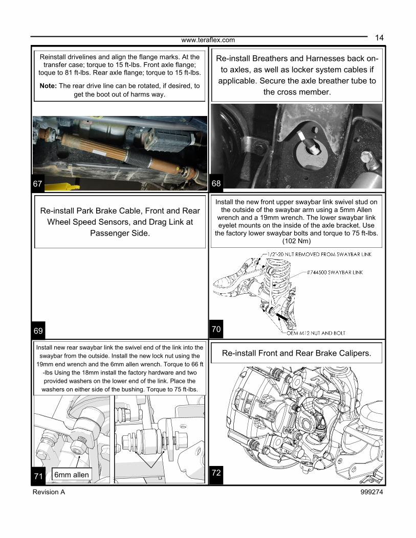
Install the new front upper swaybar link swivel stud on the outside of the swaybar arm using a 5mm Allen
wrench and a 19mm wrench. The lower swaybar link eyelet mounts on the inside of the axle bracket. Use
the factory lower swaybar bolts and torque to 75 ft-lbs. (102 Nm)
67 68
69 70
71 72
Re-install Front and Rear Brake Calipers.
Re-install Breathers and Harnesses back on-
to axles, as well as locker system cables if
applicable. Secure the axle breather tube to
the cross member.
Reinstall drivelines and align the flange marks. At the transfer case; torque to 15 ft-lbs. Front axle flange;
toque to 81 ft-lbs. Rear axle flange; torque to 15 ft-lbs.
Note: The rear drive line can be rotated, if desired, to
get the boot out of harms way.
Re-install Park Brake Cable, Front and Rear
Wheel Speed Sensors, and Drag Link at
Passenger Side.
Install new rear swaybar link the swivel end of the link into the
swaybar from the outside. Install the new lock nut using the
19mm end wrench and the 6mm allen wrench. Torque to 66 ft
-lbs Using the 18mm install the factory hardware and two
provided washers on the lower end of the link. Place the
washers on either side of the bushing. Torque to 75 ft-lbs.

15 www.teraflex.com
Revision A 999274
Remove the soft line from the hard line with a 12mm then
remove the brake line from the frame with a 10mm.
Mount the new L bracket to the frame with the original
bolt. Insert the new line through the bracket.
Hand tighten the hard line into the new line.
Place a new copper washer on the banjo bolt and insert though
the end of the brake line. Place another copper washer between
the fitting and the caliper.
Rear Brake Line Install
Remove the banjo bolt from the caliper with a 15mm. Use a
pan to catch the released fluid.
73 74
75 76
77 78
Orient the line as shown on the caliper. Torque banjo bolt to
23 ft-lbs.
Front Brake Line Install
Remove the banjo bolt from the caliper with a 15mm. Use a
pan to catch the released fluid.

16 www.teraflex.com
Revision A 999274
14ft-lbs.
Clip
79 80
81 82
83 84
Remove the brake line from the hard line with a 12mm.
Remove the line from the frame with a 10mm.
Install the new L bracket onto the frame with the origi-
nal bolt. Insert the new line through the bracket. Hand
tighten the hard line into the new line.
Place a new copper washer on the banjo bolt and insert though
the end of the brake line. Place another copper washer between
the fitting and the caliper.
Orient the line as shown on the caliper. Torque banjo bolt to
23 ft-lbs.
Bleed the brakes according to standard proce-
dure. Starting with the rear right tire, the right to
left, back to front.
Make sure the brake lines will not snag on any compo-
nents as the suspension cycles. Tip: Zip tie the soft
brake line to the rear swaybar link (away from the tire).
Torque the hard line fitting to 14 ft-lbs
install the retainer clip.
Zip Tie

17 www.teraflex.com
Revision A 999274
We installed the lines so that the anchor was
pulled slightly toward the tire when it was turned
out. This was to help the lines stay clear of the tire
when it is turned the opposite way.
Loosely install the rest of the cable ties.
Snug down the shock bolt.
If there is plenty of length to your lines then mount the anchor on the inside, directly under the nut.
If your lines are stiff or length is an issue it might be better to install the anchor on the out side of the shock
mount. Notes: *Use a large screwdriver or pry bar under the
shock to help install shock mount bolt.* *Do not tighten the shock mount bolt*
Once the anchor is installed then install the ABS
line into the anchor followed by the brake line.
(see picture)
Next, loosely install a cable tie. Inspect the lines
and adjust the line positions as needed.
Repeat steps 35 to 40 for the other side.
The Rubber Brake Line Anchor can be mounted
on the inside or outside of the bottom shock
mount bolt.
Installation of Brake Line Anchor
Use some cable ties to route the ABS and brake lines
together so they are uniform and equal.
Note: Zip ties provided in the kit are for mounting the lines to the Anchor. Extra cable ties can be picked up
from just about any hardware store.
85 86
87 88
89 90
18 www.teraflex.com
Revision A 999274
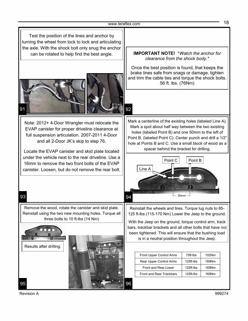
Note: 2012+ 4-Door Wrangler must relocate the
EVAP canister for proper driveline clearance at
full suspension articulation. 2007-2011 4-Door
and all 2-Door JK’s skip to step 76.
Locate the EVAP canister and skid plate located
under the vehicle next to the rear driveline. Use a
16mm to remove the two front bolts of the EVAP
canister. Loosen, but do not remove the rear bolt. Line A
Point B Point C
50mm
Test the position of the lines and anchor by
turning the wheel from lock to lock and articulating
the axle. With the shock bolt only snug the anchor
can be rotated to help find the best angle. IMPORTANT NOTE! *Watch the anchor for clearance from the shock body.*
Once the best position is found, that keeps the brake lines safe from snags or damage, tighten
and trim the cable ties and torque the shock bolts. 56 ft. lbs. (76Nm)
Remove the wood, rotate the canister and skid plate.
Reinstall using the two new mounting holes. Torque all
three bolts to 10 ft-lbs (14 Nm)
Mark a centerline of the existing holes (labeled Line A).
Mark a spot about half way between the two existing
holes (labeled Point B) and one 50mm to the left of
Point B. (labeled Point C). Center punch and drill a 1/2”
hole at Points B and C. Use a small block of wood as a
spacer behind the bracket for drilling.
Reinstall the wheels and tires. Torque lug nuts to 85-
125 ft-lbs (115-170 Nm) Lower the Jeep to the ground.
With the Jeep on the ground, torque control arm, track
bars, trackbar brackets and all other bolts that have not
been tightened. This will ensure that the bushing load
is in a neutral position throughout the Jeep.
Front Upper Control Arms 75ft-lbs 102Nm
Rear Upper Control Arms 125ft-lbs 169Nm
Front and Rear Lower 125ft-lbs 169Nm
Front and Rear Trackbars 125ft-lbs 169Nm
91
93 94
95
92
96
Results after drilling.

19 www.teraflex.com
Revision A 999274
Front of Jeep
Rear
Perform a final check of the suspension com-ponents and bolts.
Important: Your Jeep will require a 4 wheel alignment to be road worthy.
After wheel alignment install the rear lower bumpstop pads.
Before test driving the Jeep, do a quick visual check and make sure the tires are straight. Adjust the drag link as needed to center the steering wheel. Drive a
short distance down a straight road and, if necessary, readjust the steering wheel to center. Torque the drag-
link adjusting sleeve to 26 ft-lbs (35 Nm).
Now that the alignment in finished and control arms are adjusted the Lower Bumpstop Pads
can be installed.
Jeeps with Monotube Falcon Shocks will be getting four 3/4” pads per side.
Jeeps with Piggyback Falcon Shocks will be getting three 3/4” pads per side.
98
99 100
101
97
Install is now Complete
Maintenance Note: After the first 100 miles and every 3,000 miles after that, re-torque all
the suspension components and bolts.
102
Locate the rear lower bumpstop pad (954600) and posi-
tion pad with the extended end facing the front of the
Jeep, as shown.
Each pad will receive two 179 bolts and two 630 Nylock
nuts. Finish up the installation by torqueing each of the
4 fasteners to 7 ft-lbs (9.5 Nm).
3/4” pads

www.teraflex.com
20
Revision A 999274
TERAFLEX, Inc. 5680 West Dannon Way West Jordan, Utah 84081 Phone/801.713.3314 Fax/801.713.2313 www.teraflex.com
PRODUCT INFORMATION MAINTENANCE INFORMATION:
It is the buyer’s responsibility to have all suspension, drivetrain, steering, and other components checked for proper tightness and torque after the first 100 miles
and every 3000 miles after that.
NOTICE TO INSTALLER:
The enclosed “Warning to Driver” sticker must be installed in the vehicle in driver’s view. This sticker is to act as a constant safety reminder when operating the
vehicle. It is your responsibility as the equipment installer to install the provided sticker and to forward the product instructions to the vehicle’s owner for review. If a
“Warning to Driver” sticker or product installation guide were not included in the kit, FREE replacement stickers and instructions are available by request. It is the
installer’s duty to ensure a safe and controllable vehicle after the modifications have been performed.
WARNING:
Neither the seller nor the manufacturer will be liable for any loss, damage, or injury directly or indirectly arising from the use of or inability to determine the use of
these products. Before using, the user shall determine the suitability of the products for its intended use, and the user shall assume all responsibility and risk in
connection therewith.
WARNING TO DRIVER:
This vehicle has been modified to enhance off road performance and has unique handling characteristics. Use in harsh environments can cause extreme stress
on the components. Vehicle should be inspected after being off road to make sure that all the components are in working order and safe to travel on the highway.
All fasteners should be checked so that they are at the correct torque specifications as the vibration and stresses from off roading may cause critical fasteners to
work loose. Extra care should be taken to inspect the critical components, steering, and brake systems. During each oil change components such as arms, tie rod
ends, etc should be greased and checked for excessive wear. Any worn components should be replaced. When returning to the pavement always set or restore
tire air pressure to the factory recommendation and connect or engage any disabled sway bar mechanisms. Because of the higher center of gravity and larger
tires, this vehicle handles and reacts differently than many passenger cars, both on and off road. You must drive it safely! Extreme care should be taken to prevent
vehicle rollover or loss of control, which can result in serious injury or death. Avoid sudden sharp turns or abrupt maneuvers. Generally, braking performance and
capabilities are decreased when significantly larger/heavier tires are used, especially when used in combination with transfer case low-range reduction kits. Take
this into consideration while driving. Do not add, alter or fabricate any factory or aftermarket parts to increase vehicle height over the intended height of the Tera-
Flex product purchased. Mixing component brand is not recommended. TeraFlex Inc. will not be responsible for any altered product or any improper installation or
use of our products. We will be happy to answer any questions concerning the design, function, and correct use of our products. It is ultimately the buyer’s respon-
sibility to have all bolts/nuts checked for tightness after the first 100 miles and then every 3000 miles. Wheel alignment, steering system, suspension and drive line
systems must be inspected by a qualified professional mechanic at least every 3000 miles.
TERAFLEX PRODUCT WARRANTY:
TeraFlex Inc. warrants TeraFlex Suspension products to the original retail purchaser to be free of defects in material and workmanship for as long as the original
purchaser owns the vehicle on which products were originally installed.
Failure to complete regular maintenance (grease every 3000 miles) on TeraFlex FlexArms will void this warranty. All other conditions of the standard TeraFlex
product warranty apply.
All TeraLow products are covered by the TeraFlex two (2) year warranty to be free of defects in material and workmanship for two years from date purchased.
TeraFlex axles are covered by a 12-month warranty to be free of defects in materials and workmanship.
This warranty does not cover or include product finish, improperly installed or applied products, improperly maintained products, products or components used for
racing or competition or damage due to abuse or neglect, products that fail due to the use of larger tire and wheel combinations.
All returns must be accompanied by an original invoice. It is the customer’s responsibility to remove the product from the vehicle. Shipping charges are the respon-
sibility of the customer. TeraFlex Inc. will pay the return freight if the product meets the terms of warranty.
This warranty is for the replacement or repair of defective TeraFlex products only and does not include freight charges, labor charges for removal of or installation
of TeraFlex or related products or components, costs incurred due to down time of the vehicle, or lost profits due to vehicle down time.
A returned goods authorization number (RGA#) must accompany any returned products. For more information please contact a TeraFlex customer service repre-
sentative.
COPYRIGHT
©Copyright 2014. All rights reserved, TeraFlex Inc. Reproduction of this catalog and/or any of its contents without written permission is strictly prohibited.
TeraFlex® is a registered trademark of TeraFlex Inc. All trade names and logos including but not limited to TeraFlex, FlexArms, RockGuard, Monster, and
LCG are protected by law and duplication of trade names and/or logos are strictly prohibited.
TeraFlex Inc. reserves the right to update, discontinue, redesign, modify finish, part number or component build parts if deemed necessary without written notice.
TeraFlex Inc., and any associated dealers are not responsible for misprints or typographical errors that may have inadvertently been made within this instruction
sheet.
Jeep® and the Jeep® grill are registered trademarks of Fiat Chrysler Automobiles N.V., and have no affiliation with TeraFlex Inc.