
Alloy Solutions to Metal Dusting Problems in the Chemical Processing Industry
8
Alloy Solutions to Metal Dusting Problems in the PetroChemical Industry Brian A. Baker and Gaylord D. Smith, Special Metals Corporation, Huntington, WV, USA Producing chemical derivatives of the refining process often involves the creation of a synthesized gas (syngas) stream consisting of a mixture of CO, H 2 and H 2 O with lower levels of CO 2 and some CH 4 . The synthesis and reducing gases derived by reforming processes are used as the basic feedstock in the production of plastics, synthetics, fertilizers, fibers and pharmaceuticals. When such gas mixtures are present in the process stream in the critical temperature range of about 400° to 800°C, the phenomenon labeled “metal dusting” can potentially be a severe corrosion problem. Past and present failures resulting from metal dusting have prompted end users and material producers alike to examine the causes of and potential solutions to this often-disastrous problem. Metal dusting can be described as a catastrophic carburization phenomenon which occurs under conditions where the carbon activity of the gaseous atmosphere is greater than one. Metal dusting is manifested by the disintegration of the affected metal into a powdery mixture of graphite and metal particles. Oxides and carbides are also often present in the powdery mixture or 'dust'. Special Metals corporation, which includes the business formerly known as Inco Alloys International, has been actively involved in characterizing and developing new materials to cope with the increasing demand on equipment in harsh metal dusting environments. Research has been conducted on a number of alloys, apart from the traditionally used primary and secondary reformer material INCOLOY® alloy 800H, to better understand the role of alloying in resisting attack. This article presents long term laboratory data and shows how the consideration of alloy content can be effective in resisting metal dusting attack. Causes of Metal Dusting The production of syngas from methane or natural gas via steam reforming is a common step to begin production of hydrogen, ammonia, methanol and liquid hydrocarbons (via Fischer Tropsch synthesis). The amount of steam used for the reforming process has been driven lower by the need for greater efficiency, resulting in lower steam-to- hydrogen ratios. Higher front-end pressures have also increased the CO content of the syngas. Lower H 2 O/H 2 ratios in combination with higher CO/CO 2 ratios result in lower oxygen partial pressures and higher carbon activities, respectively , and serve to increase the severity of metal dusting attack. Metal dusting is often avoided in industry by designing around the critical metal dusting temperature range. Syngas is produced at temperatures above the critical range (>800°C) and transferred to a boiler via a short transfer line where it is rapidly quenched to temperatures below the critical metal dusting range (<400°C). Alloy ferrules that are used in the transfer line do often experience metal dusting and are periodically replaced. The need to maximize the efficiency of steam reforming technology has led to the development of equipment which must be capable of operating within the range of temperature and carbon activity which can promote metal dusting. This necessitates the use of materials which exhibit excellent resistance to metal dusting attack. Exploration of the range of conditions which produce metal dusting is being conducted intensively worldwide through consortia such as those coordinated by the Materials Technology Institute in the USA and the TNO Institute of Industrial Technology in Europe. 1 The mechanism of metal dusting for iron-base alloys begins with saturation of the alloy matrix with carbon/carbides, usually in a localized manner, and subsequent formation of metastable Fe 3 C, or cementite. Decomposition of the cementite as the carbon activity approaches unity produces iron particles and powdery carbon. The metal particles then strongly catalyze further carbon deposition. A different mechanism is proposed for nickel- base alloys, which does not involve the formation of an intermediate metastable carbide. Such a mechanism begins in the same way as for iron-base alloys, with saturation of the alloy matrix with carbon/carbides. However, in the case of nickel-base alloys, the saturated matrix directly decomposes into metal particles and graphite. 2,3 Figure 1 illustrates the equidistant diffusion (assuming a material which exhibits isotropic diffusion behavior) of carbon from a point defect in the protective oxide scale which results in saturation of a hemispherical region with carbon. Subsequent decomposition of this saturated area results in disintegration of the alloy matrix and not simply grain fallout, producing a pit having the same hemispherical shape as the carbon-saturated region.
-
Upload
giuseppe-di-ruocco -
Category
Documents
-
view
40 -
download
1
Transcript of Alloy Solutions to Metal Dusting Problems in the Chemical Processing Industry
Alloy Solutions to Metal Dusting Problems in the PetroChemical Industry
Brian A. Baker and Gaylord D. Smith, Special Metals Corporation, Huntington, WV, USA
Producing chemical derivatives of the refining process often involves the creation of a synthesized gas (syngas)stream consisting of a mixture of CO, H2 and H2O with lower levels of CO2 and some CH4. The synthesis andreducing gases derived by reforming processes are used as the basic feedstock in the production of plastics,synthetics, fertilizers, fibers and pharmaceuticals. When such gas mixtures are present in the process stream in thecritical temperature range of about 400° to 800°C, the phenomenon labeled “metal dusting” can potentially be asevere corrosion problem. Past and present failures resulting from metal dusting have prompted end users andmaterial producers alike to examine the causes of and potential solutions to this often-disastrous problem.
Metal dusting can be described as a catastrophic carburization phenomenon which occurs under conditions wherethe carbon activity of the gaseous atmosphere is greater than one. Metal dusting is manifested by the disintegration ofthe affected metal into a powdery mixture of graphite and metal particles. Oxides and carbides are also often presentin the powdery mixture or 'dust'.
Special Metals corporation, which includes the business formerly known as Inco Alloys International, has beenactively involved in characterizing and developing new materials to cope with the increasing demand on equipmentin harsh metal dusting environments. Research has been conducted on a number of alloys, apart from thetraditionally used primary and secondary reformer material INCOLOY® alloy 800H, to better understand the role ofalloying in resisting attack. This article presents long term laboratory data and shows how the consideration of alloycontent can be effective in resisting metal dusting attack.
Causes of Metal Dusting
The production of syngas from methane or natural gas via steam reforming is a common step to begin productionof hydrogen, ammonia, methanol and liquid hydrocarbons (via Fischer Tropsch synthesis). The amount of steamused for the reforming process has been driven lower by the need for greater efficiency, resulting in lower steam-to-hydrogen ratios. Higher front-end pressures have also increased the CO content of the syngas. Lower H2O/H2 ratiosin combination with higher CO/CO2 ratios result in lower oxygen partial pressures and higher carbon activities,respectively , and serve to increase the severity of metal dusting attack. Metal dusting is often avoided in industryby designing around the critical metal dusting temperature range. Syngas is produced at temperatures above thecritical range (>800°C) and transferred to a boiler via a short transfer line where it is rapidly quenched totemperatures below the critical metal dusting range (<400°C). Alloy ferrules that are used in the transfer line dooften experience metal dusting and are periodically replaced. The need to maximize the efficiency of steamreforming technology has led to the development of equipment which must be capable of operating within the rangeof temperature and carbon activity which can promote metal dusting. This necessitates the use of materials whichexhibit excellent resistance to metal dusting attack. Exploration of the range of conditions which produce metaldusting is being conducted intensively worldwide through consortia such as those coordinated by the MaterialsTechnology Institute in the USA and the TNO Institute of Industrial Technology in Europe.1
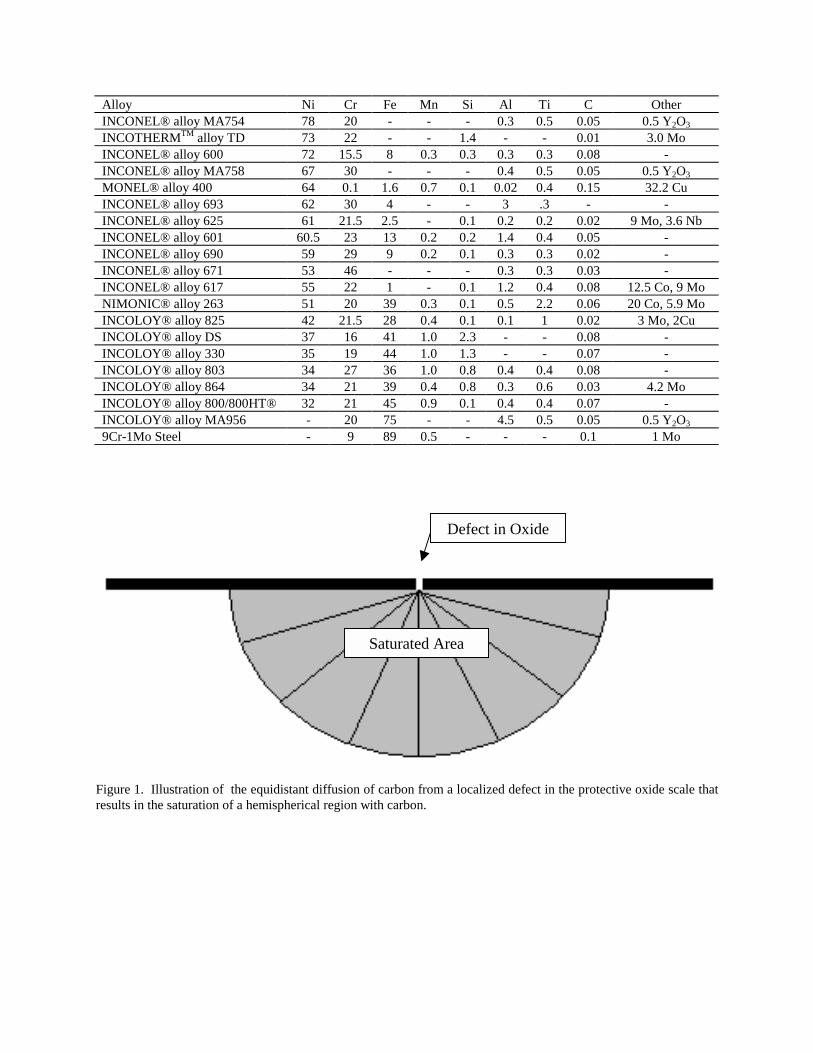
The mechanism of metal dusting for iron-base alloys begins with saturation of the alloy matrix withcarbon/carbides, usually in a localized manner, and subsequent formation of metastable Fe3C, or cementite.Decomposition of the cementite as the carbon activity approaches unity produces iron particles and powdery carbon.The metal particles then strongly catalyze further carbon deposition. A different mechanism is proposed for nickel-base alloys, which does not involve the formation of an intermediate metastable carbide. Such a mechanism beginsin the same way as for iron-base alloys, with saturation of the alloy matrix with carbon/carbides. However, in thecase of nickel-base alloys, the saturated matrix directly decomposes into metal particles and graphite.2,3 Figure 1illustrates the equidistant diffusion (assuming a material which exhibits isotropic diffusion behavior) of carbon froma point defect in the protective oxide scale which results in saturation of a hemispherical region with carbon.Subsequent decomposition of this saturated area results in disintegration of the alloy matrix and not simply grainfallout, producing a pit having the same hemispherical shape as the carbon-saturated region.
Protection of an alloy against metal dusting attack requires the presence of an adherent, protective, healable oxidesurface layer. While oxide formation may be stable, the oxide layer may still be susceptible to disruption. Higherlevels of the scale forming element will then make the scale healing process more rapid and complete. Ultimateresistance to metal dusting may involve complex interactions of scale characteristics, diffusivity of scale-formingelements and carbon through the alloy matrix and carbon saturation limits.
Alloy Performance in Metal Dusting Environments
Changing processing conditions and the use of advanced catalysts have heightened the tendency of synthetic gasstreams to promote metal dusting. Techniques such as injection of additional steam and sulfur-containing speciesinto the gas stream, which are known to minimize the effects of metal dusting, are no longer viable in manyprocesses due to the increased use of catalysts which are sensitive to sulfur content. Higher gas pressures andtemperatures, in conjunction with lower H2O/H2 ratios and higher CO/CO2 ratios are becoming the norm for modernreforming operations. This combination of conditions may necessitate the use of materials which offer resistance tometal dusting that is superior to that of previously commonly used alloys such as the Cr-Mo stainless steels and Fe-Ni-Cr alloys.
Two commonly used alloys that typically offer good overall corrosion resistance as well as high temperaturestrength under a wide range of conditions are INCONEL® alloy 600 and INCOLOY alloy 800H. Metal dustingfailures of alloy 800 are well documented4,5 and problems with alloy 600 have been encountered as well. Figures 2and 3 show metal dusting attack of both the alloy 600 piping and the alloy 800 connecting ring, respectively, from areformer pigtail.6 The reformer had been in service for about 5 years. Harsher conditions have necessitated the useof alloys having high nickel contents in additional to higher levels of scale-forming elements, such as chromium.Alloy 601 has been used for waste heat boiler shells and tubing in ammonia plants as well as for reformercomponents and has resulted in greater production due to decreases in downtime and repair costs. For even greaterprotection against metal dusting under the harshest conditions, alloys such as INCOTHERMTM alloy TD, INCOLOYalloy MA956, INCOCLAD® 671/800HT and INCONEL alloy 617, INCONEL alloy 690,and INCONEL alloy 693,offer promising potential as an upgrade from the commonly used alloy 601.
Laboratory Testing
Table 1 shows the chemical composition for each alloy tested as well as for other alloys mentioned in this article.Test specimens were prepared from commercially available material; sample dimensions were approximately 2.5cmX 2.5cm X thickness. Samples were ground to a 120-grit finish for standardization purposes.
Exposures were performed at 621°C in an atmosphere generated from an inlet gas mixture of CO-20% H2. Sampleswere cycled, lightly brushed and ultrasonically cleaned and mass change was measured at approximately two-weekintervals. In addition to mass change, pitting depth was also determined for each sample using an optical microscopehaving a calibrated fine focus knob.
Figure 4 shows mass loss rates versus time for the alloys tested. The rate was calculated by dividing the masschange (only shown if negative) per unit area by the total test time. The maximum pit depth as a function of time isplotted in Figure 5. Figure 6 shows the result of multiple regression analysis of the log of the pit progression rate,calculated by averaging the pit depth over the total testing duration, versus the weight percentage of various alloyingadditions. Only the austentic nickel-base alloys and Fe-Ni-Cr alloys were included in this calculation; the twoferritic alloys, MA956 and Fe-9Cr-1Mo, and also alloy 400 were excluded. The best fit was produced using thefollowing summation:
Log (Pit Progression Rate in µ/h) = (%Ni+%Co)+5*%Mo+20*%Ti+33*%Al+15*%Si+2*%Cr-2*%Fe.
This same regression technique was used to characterize the variation in mass loss rate with the percentage of certainalloying additions (Figure 7). Again, only the austenitic nickel-base and Fe-Ni-Cr alloys were included in thecalculation. The best fit was obtained using the following summation:
Log (Mass Loss Rate in mg/cm2/h = 2*(%Ni+%Co)+6*%Mo+31*%Ti+34*%Al+80*%Si+9*%Cr-%Fe.
As a general trend, nickel-base alloys exhibited lower mass loss rates and pitting progression rates than iron-basealloys. Exceptions include alloys 600 and MA754, which contain only 15% and 20% chromium and have no othersignificant additions of scale-forming or carbide-forming elements, and had a fairly high mass loss rate resultingfrom numerous, albeit fairly shallow, pits. Alloy 690 (Ni-29Cr-9Fe), commonly used as heat-exchanger tubing in thenuclear industry, exhibits much lower mass loss and pit progression rates than alloy 601 which is increasingly usedas an upgrade from iron-base materials such as Cr-Mo steels, austenitic stainless steels and Fe-Ni-Cr heat-resistantalloys such alloy 800. The mechanically alloyed corollary to alloy 690, alloy MA758, also exhibits goodperformance. Alloy MA956, a ferritic alumina former, also exhibited good performance. Alloy 263 performed welldespite its modest chromium level of 20% and 39% iron content, and appears to possibly gain protection from itssubstantial titanium addition and possibly its molybdenum addition, which may promote early carbide formation andprovide diffusional blocking of the carbon flux.7. Alloy 617, having 22% chromium and 1.2 aluminum, may alsogain benefit from its molybdenum addition. Alloy 625 has performed reasonably well and contains 21.5%chromium, 9% molybdenum and 3.6% niobium. The new high silicon content of INCOTHERM alloy TD may haveafforded some enhancement in performance, in addition to its 3% molybdenum content.
The INCONEL alloy 671 and alloy 693 show the highest performance in both resisting pitting attack and resistingmass loss, contain the highest combinations of nickel, chromium and aluminum. The protection of the material beingenhanced by the very high level of scale-forming elements which form a dense, adherent and self healing protectiveoxide surface layer. Alloy 671, with its substantial chromium content, has performed well and could be utilized in theform of a bimetallic clad tube, being mechanically very poor as a monolithic material within the metal dustingtemperature range. INCOCLAD tubes having an alloy 671 layer on the OD and alloy 800HT® at the ID have beensuccessfully used in coal-fired boilers with service times exceeding 20 years. The best performer overall in thelaboratory test was alloy 693, which possesses very high chromium and aluminum contents. In-situ field exposuresin syngas environments have confirmed this alloy's superior performance.
Conclusion
Due to development of advanced catalysts and efforts to increase the efficiency of processes involving theproduction of syngas, metal dusting corrosion has become more prevalent. Failures of iron-base alloys as well asnickel-base alloys which contain insufficient scale-forming elements have prompted equipment designers to seekmaterials that are more resistant to metal dusting. Field and laboratory data confirm the desirability of addition ofcertain scale-forming and carbide-forming elements in conjunction with a nickel-base alloy matrix to limit pitprogression rates.
Acknowledgements
The authors would like to thank Chad Clary for his assistance with laboratory testing and sample evaluation.
References:
1) R. T. Jones and K. L. Baumert, Paper No. 1372, CORROSION/2001, NACE International, 2001.2) E. Pippel, J. Woltersdorf, R. Schneider, Materials and Corrosion, 49, 1998, pp 309-316.3) H. J. Grabke, Materials and Corrosion, 49, 1998, pp 303-308.4) Lai, G. Y., “ High Temperature Corrosion of Engineering Alloys”, ASM, 1990, pp 69-72.5) “Handbook of Case Histories in Failure Analysis,” Esaklul, K. A., ed., ASM, 1992, pp 351-353.6) Private Communication, Special Metals, December, 1997.7) S. Strauss and H. J. Grabke, Materials and Corrosion, 49, 1998, pp 321-327.
INCOCLAD®, INCONEL®, INCOLOY®, INCOTHERMTM, MONEL®, NIMONIC® and 800HT® aretrademarks of the Special Metals group of companies.
Table 1. Nominal Composition of Commercial Alloys
Alloy Ni Cr Fe Mn Si Al Ti C OtherINCONEL® alloy MA754 78 20 - - - 0.3 0.5 0.05 0.5 Y2O3
INCOTHERMTM alloy TD 73 22 - - 1.4 - - 0.01 3.0 MoINCONEL® alloy 600 72 15.5 8 0.3 0.3 0.3 0.3 0.08 -INCONEL® alloy MA758 67 30 - - - 0.4 0.5 0.05 0.5 Y2O3
MONEL® alloy 400 64 0.1 1.6 0.7 0.1 0.02 0.4 0.15 32.2 CuINCONEL® alloy 693 62 30 4 - - 3 .3 - -INCONEL® alloy 625 61 21.5 2.5 - 0.1 0.2 0.2 0.02 9 Mo, 3.6 NbINCONEL® alloy 601 60.5 23 13 0.2 0.2 1.4 0.4 0.05 -INCONEL® alloy 690 59 29 9 0.2 0.1 0.3 0.3 0.02 -INCONEL® alloy 671 53 46 - - - 0.3 0.3 0.03 -INCONEL® alloy 617 55 22 1 - 0.1 1.2 0.4 0.08 12.5 Co, 9 MoNIMONIC® alloy 263 51 20 39 0.3 0.1 0.5 2.2 0.06 20 Co, 5.9 MoINCOLOY® alloy 825 42 21.5 28 0.4 0.1 0.1 1 0.02 3 Mo, 2CuINCOLOY® alloy DS 37 16 41 1.0 2.3 - - 0.08 -INCOLOY® alloy 330 35 19 44 1.0 1.3 - - 0.07 -INCOLOY® alloy 803 34 27 36 1.0 0.8 0.4 0.4 0.08 -INCOLOY® alloy 864 34 21 39 0.4 0.8 0.3 0.6 0.03 4.2 MoINCOLOY® alloy 800/800HT® 32 21 45 0.9 0.1 0.4 0.4 0.07 -INCOLOY® alloy MA956 - 20 75 - - 4.5 0.5 0.05 0.5 Y2O3
9Cr-1Mo Steel - 9 89 0.5 - - - 0.1 1 Mo
Figure 1. Illustration of the equidistant diffusion of carbon from a localized defect in the protective oxide scale thatresults in the saturation of a hemispherical region with carbon.
Saturated Area
Defect in Oxide
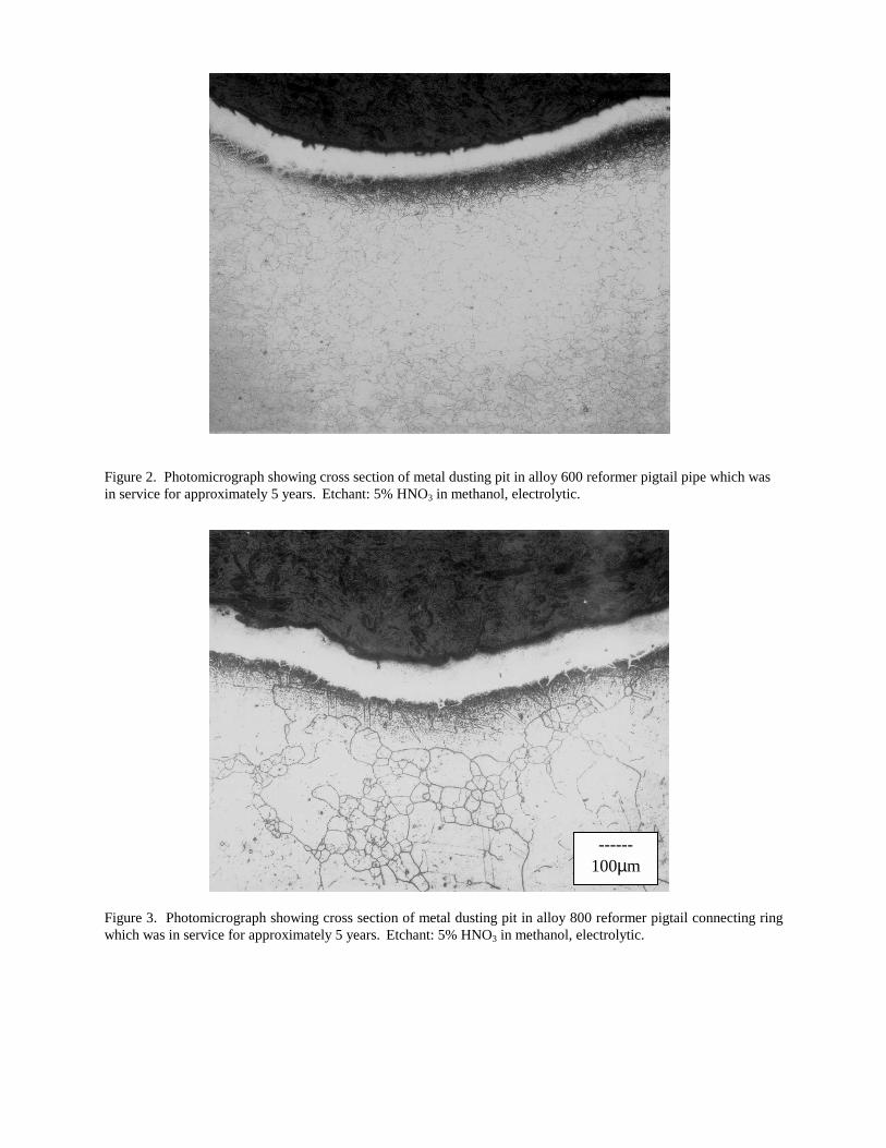
Figure 2. Photomicrograph showing cross section of metal dusting pit in alloy 600 reformer pigtail pipe which wasin service for approximately 5 years. Etchant: 5% HNO3 in methanol, electrolytic.
Figure 3. Photomicrograph showing cross section of metal dusting pit in alloy 800 reformer pigtail connecting ringwhich was in service for approximately 5 years. Etchant: 5% HNO3 in methanol, electrolytic.
------100µm
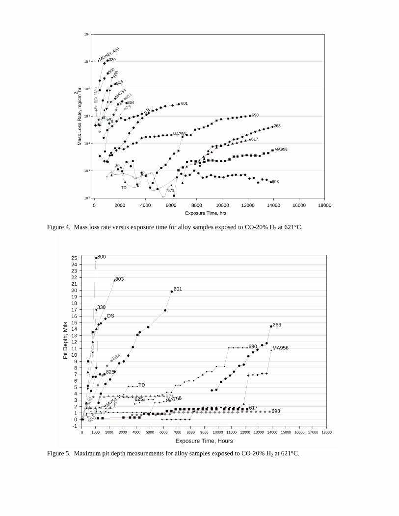
Figure 4. Mass loss rate versus exposure time for alloy samples exposed to CO-20% H2 at 621°C.
Figure 5. Maximum pit depth measurements for alloy samples exposed to CO-20% H2 at 621°C.
Exposure Time, Hours0 1000 2000 3000 4000 5000 6000 7000 8000 9000 10000 11000 12000 13000 14000 15000 16000 17000 18000
Pit D
epth
, Mils
-10123456789
10111213141516171819202122232425
MA956
263
693
864
617
690
671MA758
MA754
400
330
600
601
800
803
DS
825
TD
625
Exposure Time, hrs0 2000 4000 6000 8000 10000 12000 14000 16000 18000
Mas
s Lo
ss R
ate,
mg/
cm2 hr
10-6
10-5
10-4
10-3
10-2
10-1
100
MA956
Fe-9
Cr-1
Mo
263
864
693
617
690
671
MA758
MA754825
DS
803
800
601
600
330MONEL 400
625
TD
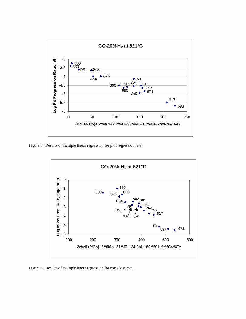
Figure 6. Results of multiple linear regression for pit progression rate.
Figure 7. Results of multiple linear regression for mass loss rate.
CO-20%H2 at 621°C
-6
-5.5
-5
-4.5
-4
-3.5
-3
0 50 100 150 200 250
(%Ni+%Co)+5*%Mo+20*%Ti+33*%Al+15*%Si+2*(%Cr-%Fe)
Log
Pit P
rogr
essi
on R
ate,
µµ µµ/h
800330
DS 803
864825
601600
690263754 TD
625671758
617693
CO-20% H2 at 621°C
-6
-5
-4
-3
-2
-1
0
100 200 300 400 500 600
2(%Ni+%Co)+6*%Mo+31*%Ti+34*%Al+80*%Si+9*%Cr-%Fe
Log
Mas
s Lo
ss R
ate,
mg/
cm2 /h
800330
600825
864 803
DS
754 625
690263758
617
TD693 671
601


