
Alloy 625 – Impressive Past/Significant Presence/Awesome Future
12
ALLOY 625 - IMPRESSIVE PASTISIGNIFICANT PRESENCEIA WESOME FUTURE G. D. Smith*, D. J. Tillack*" and S. J. Patel* *Special Metals Corporation **Tillack Metallurgical Consulting, Inc. 3200 Riverside Drive 127 Woodland Drive Huntington, WV 25705 Huntington, WV 25705 ABSTRACT It has been close to half a century since the original research and development lead to the invention of alloy 625. Originally intended for ultra-critical steam piping, the alloy continues to find new applications and increased volume of production annually. This paper will review some of the markets where alloy 625 is the material of choice and explain the reasons for its success. Advances in material processing are noted and characterized. These advances are creating a better understanding of the uniqueness of the alloy and resulting in new uses. Welding and overlaying with alloy 625 for some developing applications will be reviewed. Superallo), s 7 18. 633. 706 and Various Derivatives Etlirsd b\ E.A Loria 'I'XIS (The XIincrals. \lctals ~t \larzrials Society). 2001
Transcript of Alloy 625 – Impressive Past/Significant Presence/Awesome Future

ALLOY 625 - IMPRESSIVE PASTISIGNIFICANT PRESENCEIA WESOME FUTURE
G. D. Smith*, D. J. Tillack*" and S. J. Patel*
*Special Metals Corporation **Tillack Metallurgical Consulting, Inc. 3200 Riverside Drive 127 Woodland Drive
Huntington, WV 25705 Huntington, WV 25705
ABSTRACT
I t has been close to half a century since the original research and development lead to the invention of alloy 625. Originally intended for ultra-critical steam piping, the alloy continues to find new applications and increased volume of production annually. This paper will review some of the markets where alloy 625 is the material of choice and explain the reasons for its success. Advances in material processing are noted and characterized. These advances are creating a better understanding of the uniqueness of the alloy and resulting in new uses. Welding and overlaying with alloy 625 for some developing applications will be reviewed.
Superallo), s 7 18. 633. 706 and Various Derivatives Etlirsd b\ E . A Loria
'I'XIS (The XIincrals. \lctals ~t \larzrials Society). 2001
Introduction
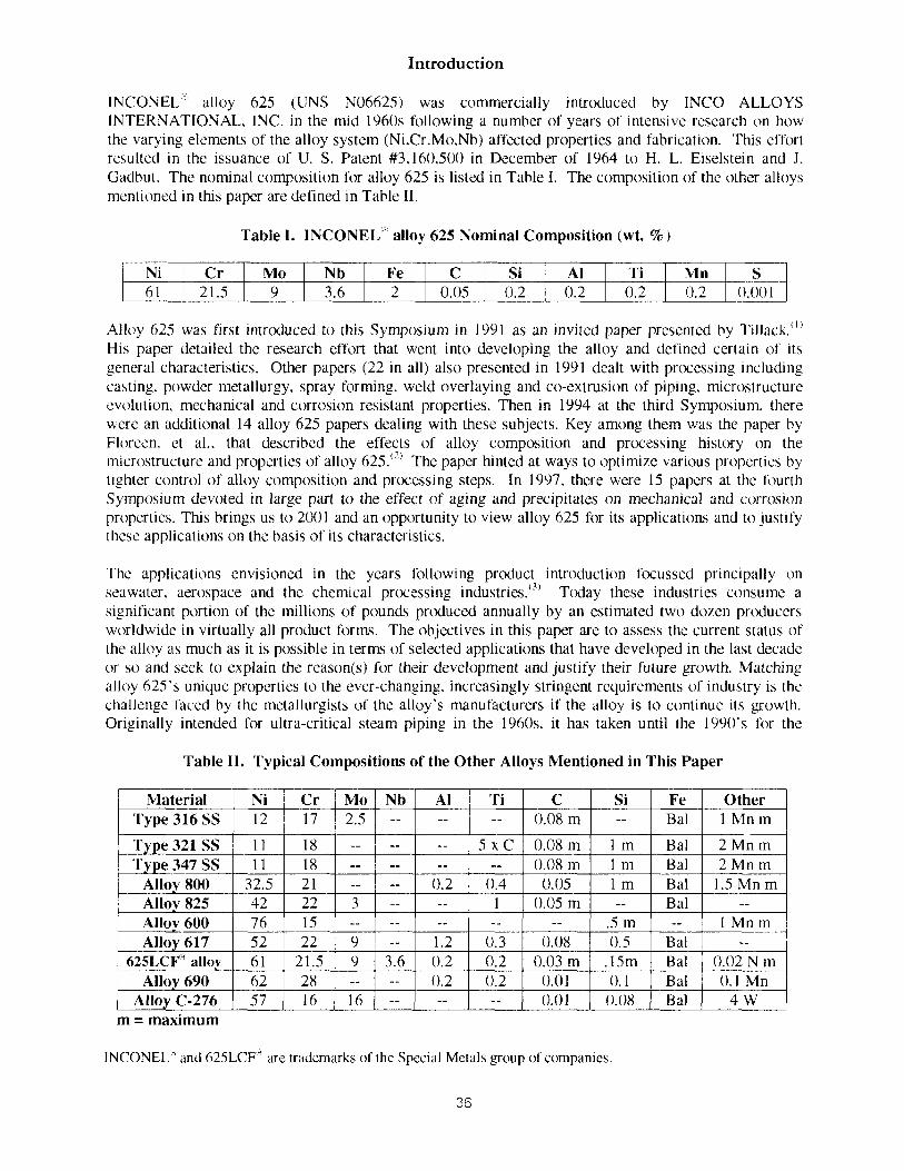
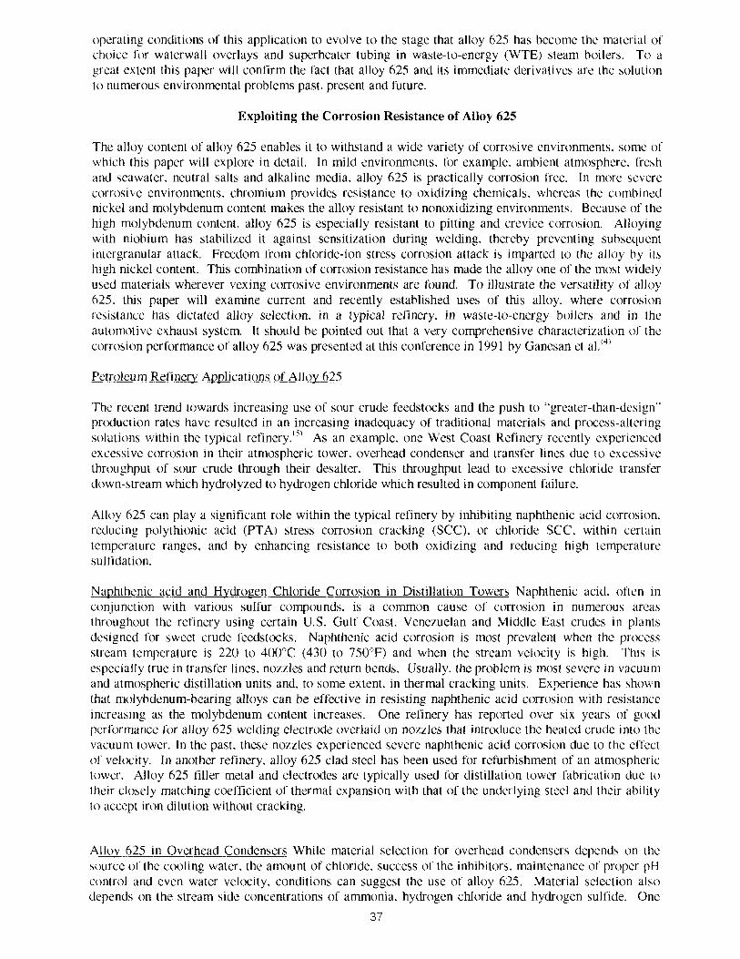
INCONEL" alloy A25 (UNS N06625) was commercially introduced by INCO ALLOYS INTERNATIONAL, INC. in the mid 1960s following a number of years of intensive research on how the varying elements of the alloy system (Ni,Cr.Mo.Nb) affected properties and fabrication. This effort resulted in the issuance of U. S. Patent #3,160.500 in December of 1964 to H. L. Eiselstein and J. Gadbut. The nominal composition for alloy 625 is listed in Table I. The composition of the other alloys mentioned in thls paper are defined in Table 11.
Table I. INCONEL' alloy 625 Nominal Composition (wt. % )
Alloy 625 was first intrtxluced to this Symposium in 1991 as an invited paper presented by ~il lack." ' His paper detailed the research effort that went into developing the alloy and defined certain of its general characteristics. Other papers (22 in all) also presented in 1991 dealt with processing including casting, powder metallurgy, spray forming, weld overlaying and co-extrusion of piping. microstructure evolution. mechanical and corrosion resistant properties. Then in 1994 at the third Symposium. there were an additional 14 alloy 625 papers dealing with these subjects. Key among them was the paper by Floreen. et al.. that described the effects of alloy composition and processing history on the microstructure and properties of alloy 625.'?' The paper hlnted at ways to optimize various properties by tighter control of alloy composition and prcxessing steps. In 1997. there were 15 papers at the fourth Symposium devoted in large part lo the effect of aging and precipitales on mechanical and corrosion properties. T h s brings us to 2001 and an opportunity to view alloy 625 for its applications and to justify thcse applications on the basis of its characteristics.
The applications envisioned in the years lbllowing product introduction focussed principally on seawater. aerospace and the chemical processing industries.'?' Today these industries conwme a significant portion of the millions of pounds produced annually by an estimated two dozen prcxiucers worldwide in virtually all product forms. The objectives in this paper are to assess the current status of the alloy as much as it is possible in terms of selected applications that have developed in the last decade or so and seek to explain the reason(s) for their development and justify their future growth. Matching alloy 625's unique properties to the ever-changing, increasingly stringent requirements of industry is the challenge faced by the metallurgists of the alloy's manufacturers if the alloy is to continue its growth. Originally intended for ultra-critical steam piping in the 1960s. it has taken until the 1990's for the
Table 11. Typical Compositions of the Other Alloys Mentioned in This Paper
I I Material I Ni / Cr / Mo I Nb I Al 1 Ti I C I Si I Fe I Other I
'I'ype316SS
'I'v~e 321 SS
m = maximum
INCONEL" and 625LCFn are trademarks of the Special Metals group of companies
Type 347 SS Alloy 800 Alloy 825
12
1 1 1 1
32.5 42
17
18 18 21 22
2.5 --
-- -- 3
--
-- -- -- --
--
-- --
0.2 --
--
5 x C --
0.4 1
0.08 m
0.08 m 0.08 m
0.05 0.05 m
--
1 m 1 m 1 m --
Bal
Bal
1 Mn m
2 Mn m Bal Bal Bal
2 Mn m 1.5 Mn m
--
operating condlt~ons of t h ~ s appl~cat~on to evolve to the stage that alloy 625 has become the material of cholce for waterwall overlays and superheater tubing In waste-to-energy (WTE) steam bo~lers. T o a great extent t h ~ s paper w ~ l l confirm the fact that alloy 625 and ~ t s immediate derival~ves are the solut~on to numerous environmental problems past, present and future.
Exploiting the Corrosion Resistance of Alloy 625
The alloy content of alloy 625 enables it to withstand a wide variety of corrosive environments. some of which this paper will explore in detail. In mild environments, for example. ambient atmosphere. Srcsh and seawater, neutral salts and alkaline media. alloy 625 is practically corrosion free. In more severe corrosive environments, chromium provides resistance to oxidizing chemicals, whereas the combined nickel and molybdenum content makes the alloy resistant to nonoxidizing environments. Because of the high molybdenum content. alloy 625 is especially resistant to pitting and crevice corrosion. Alloying with niobium has stabilized it against sensitization during welding, thereby preventing subsequent intergranular attack. Freedom from chloride-ion stress corrosion attack is imparted to the alloy by its high nickel content. T h s combination of corrosion resistance has made the alloy one of the most widely used materials wherever vexing corrosive environments are Sound. To illustrate the versatility of alloy 625. t h s paper will examine current and recently established uses of this alloy. where corrosion resistarice has dictated alloy selection, in a typical refinery. in waste-to-energy boilers and in the automotive exhaust system. It s h c ~ l d be pointed out that a very comprehensive characterization of the corrosion performance of alloy 625 was presented at t h s conference in 1991 by Ganesan et a].'''
Petroleum Reiinery Applications of Allov 625
The recent trend towards Increaslng use of sour crude feedstocks and the push to "greater-than-dcslgn" prtxluctlon rates have resulted In an lncreaslng madequacy of traditional materials and prcxcss-altcr~ng wlutlons wlthtn the typical refinery.'" As an example, one West Coast Refinery recently cxperlenced excewve conoslon In the~r atmospher~c tower, overhead condenser and transfer l~nes due to exce551ve throughput of sour crude through their desalter. Thls throughput lead to excessive chloride transfer down-stream w h c h hydrolyfed to hydrogen chlor~de w h ~ c h resulted In component failure.
Alloy 625 can play a significant role within the typical refinery by inhibiting naphthen~c a c d corrosion.
reducing polythionic acid (PTA) stress corrosion cracking (SCC). or chloride SCC. within certaln temperature ranges, and by enhancing resistance to both o x ~ d i ~ i n g and reducing high temperature sulfidat~on.
Naphthenic acid and Hydrogen Chloride Corrosion in Distillation Towers Naphthenic acid, often in conjunction with various sulfur compounds, is a common cause oi' corrosion in numerous areas throughout the refinery using certain U.S. Gulf Coast. Venezuelan and Middle East crudes in plants designed for sweet crude feedstcxks. Naphthenic acid corrosion is most prevalent when the process stream temperature is 220 to 400°C (430 to 750°F) and when the stream velwity is high. This is especially true in transfer lines, nozzles and return bends. Usually, the problem is most severe in vacuum and atmospheric distillation units and. to some extent, in thermal cracking units. Experience has shown that molybdenum-bearing alloys can be effective in resisting naphthenic acid corrosion with resistance increasing as the molybdenum content increases. One refinery has reported over six years of good performance for alloy 625 welding electrode overlaid on nozzles that introduce the heated crude into the vacuum tower. In the past, these nozzles experienced severe naphthenic acid corrosion due to the effect of velocity. In another refinery. alloy 625 clad steel has been used for refurbishment of an atmospheric tower. Alloy 625 filler metal and electrodes are typically used for distillation lower fabrication due to their closely matchlng coefficient of thermal expansion with that of the underlying steel and their ability to accept iron dilution without cracking.
Alloy 625 111 Overhead Condensers W h ~ l e matcrlal selection for overhead condenser5 depend5 on the wurce of the cooling water. the amount of chloride. success of the inhib~tors. maintenance of proper pH control and even water ve lwty , condit~ons can suggest the use of alloy 625. Materlal selection also depend5 on the meam 5rde concentrattons of amrnonla. hydrogen chlorlde and hydrogen sulfide. One
37

Latm American refinery has refurbished a battery of condensers, tuhed with 90-10 copper-nlckel tubes that suffered ammonium hydrosulfide and hydrochloride corrosion of the steel shells. by overlaymg the tube shell with alloy 625 filler metal approximately 3.2 mm (0.125 ~ n ) thlck. Increasing chlorides escapmg the crude desalter. as mentioned above. wlll Increase the use ot alloy 625 filler metal overlays In overhead condensers and their transfer llnes.
Alloy 625 i n Hvdrotreatinrr, and Hvdrocracking Units Hydrotreating uses hydrogen to remove sulfur and nitrogen from naphtha, jet fuel. diesel, gas oils and fuel oils. Ths process can result in hydrogen sulfide that causes high temperature corrosion and ammonia and ammonium sulfide that can result in lower temperature corrosion and erosion-corrosion. Additionally, PTA SCC can txcur during shutdowns. Hydrt~racking combines desulfurization with cracking to convert a full range of feedsltxks into more valuable products. The corrosion problems are similar in both hydrotreating and hydrt~racking units. While many alloys have good resistance to hydrogen sullide in the normal operating temperature of hydrotreating and hydrcxracking processes. not all these alloys have good resistance to PTA SCC and intergranular attack (IGA). These results for typical alloys used in hydrotreaters and hydrocrackers are presented in Table 111.
One component of hydrocrackers and fluid catalytic crackers where 6 2 5 ~ C F " alloy is frequently employed is the bellows expansion joint. Selection of alloy 625 is hased on well-established corrosion resistance, strength and fatigue resistance.
l ab le 111. PTA and Average IGA Results for Five Typical Alloys for Use in Hydrotreating and Hydrocracking Units.
PTA Results Time to First / Time to
IGA Results Corrosion Rate I Corrosion Rate
Material I Crack (hours) 1 Failure (hours) I (mmlyr) (Mpy)
All specimens were mill annealed plus 670°C ( 1 250°F) for one hour and air cooled.
Type 347 SS Alloy 800 Alloy 825 Alloy 625
Table IV. Application Areas and Benefits for Alloy 625 Welding Products in the Petroleum Refinery
137 Tvnc 321 SS I NC *
IGA Ta t s per ASTM A263-C. *NC = No Crackmg. **NF = No Failure in 72 hours.
NC 5
NC NC
NF**
Refinery Application Crude Transfer Lines
And Nozzles
Atmospheric Tower
3.5 NF 30 NF NF
overlays Overhead Condensers
Welding Product Alloy 625 filler metal
Alloy 625 welding electrode
Alloy 625 filler metal
Hydrotreaters and Hydrcxrackers
Welding wlth Alloy 625 w i t h the Refinery Welding and overlaying with alloy 625 filler metal and electrodes is common within the refinery for a number of reasons. These welding products closely match the coefficient of expansion of many steels. accept Iron dilution without cracking, weld readily
38
1.1 42.4 0.3 1.4
Benefits Resistance to PTA SCC & Chloride SCC
High Temperature Sulfidation & Naphthenic Acid Corrosion Resistance
Resistance to Hydrogen Chloride. Hydrogen
Alloy 625 filler metal
Hydrotreating Air Ccwlers
43 1668
13 5 5
Sulfide plus PTA S ~ C and Chloride scc Resistance to Hydrogen Chloride. Hydrogen
Alloy 625 filler metal Alloy 625 welding
electrode
Sulfide plus PTA SCC and Chloride SCC Low Coefficient of Expansion,
Iron Dilution w/o Cracking PTA and Chloride SCC Resistance
Alloy 625 filler metal Alloy 625 welding
electrode
Sulfidation. Ammonium Hydrosulfide Erosion-Corrosion Resistance
PTA & Chloride SCC Resistance
with dissimilar metals and possess the corrosion properties inherent in alloy 625. Table 1V describes areas and benefits within the relinery where welding products are uscd.
Waste-To-Energy Boiler Tube Applications for Alloy 625
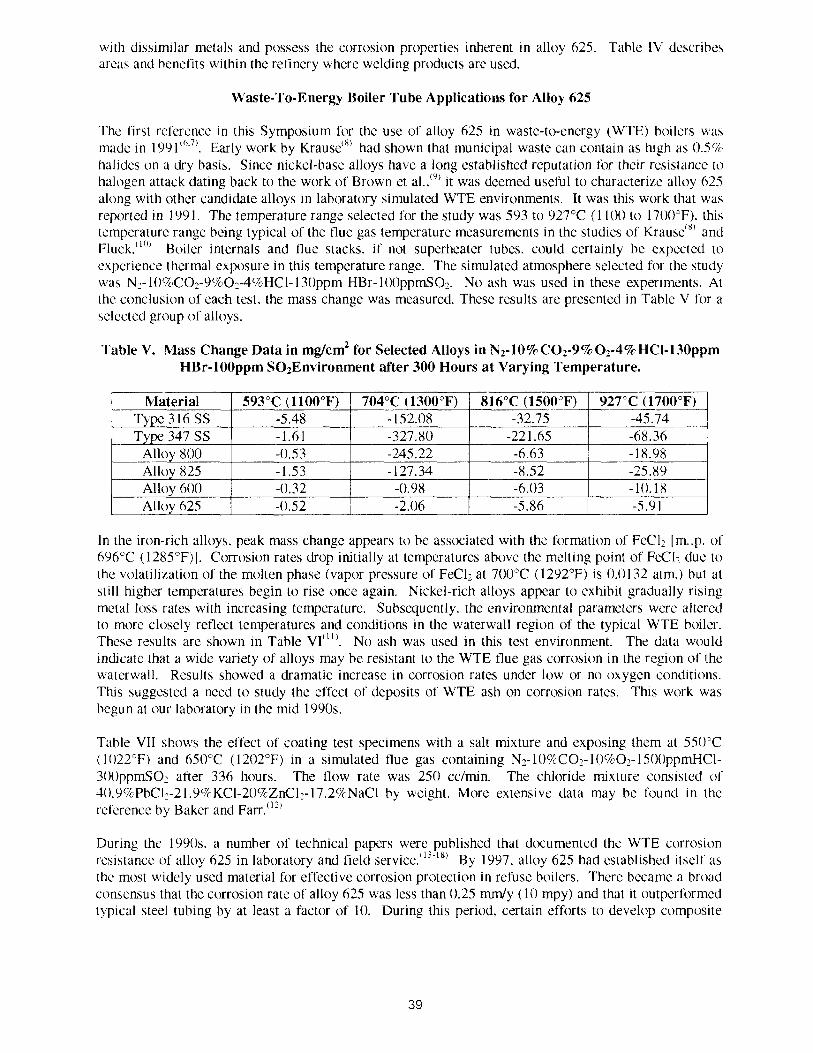
The lirst reference In t h s Symposium for the use of alloy 625 In waste-to-energy (WTE) boilers mas made in 199 I ' "~ ' . Early work by ~ r a u s e ' ~ ' had shown that munlclpal waste can contain as high as 0SCX hal~des on a dry bas~s. Since nickel-base alloys have a long established reputation for the~r resistance to halogen attack datmg back to the work of Brown et a ~ . . ' ~ ' it was deemed useful to characterire alloy 625 along with other candidate alloys in laboratory simulated WTE environments. It was t h s work that was reported In 1991. The temperature range selected for the study was 593 to 927°C (1 I00 to 1700'F). thls temperature range being typlcal of the flue gas temperature measurements in the studies of ~rause '" and luck."^)' Boiler internals and flue stacks, lf n d superheater tuba. could certainly be expected to experience thermal exposure In this temperature range. The s~mulated atmosphere selected for the study was N3- 10%C02-9%02-4ckHC1- 13Oppm HBr- 10UpprnSO2. No ash was used in these experiments. At the conclus~on of each test. the mass change was measured. These results are presented In Table V for a sclccted group ol alloys.
Table V. Mass Change Data in mg/cm2 for Selected Alloys in N2-10%C02-9%02-4%HC1-130ppm HRr-100ppm S02Environment after 300 Hours at Varying Temperature.
1 Alloy 600 -0.32 -0.98 -6.03 -10.18
Material Type 3 16 SS Type 347 SS
Alloy 800 Allov 825
In the iron-rich alloys. peak mass change appears to be associated with the formation of FeCI2 Im..p. of 696°C (1285"F)J. Corrosion rates drop initially at temperatures above the melting point of F K l , due to the volatilization of the molten phase (vapor pressure of FeC12 at 700°C (1292°F) is 0.0132 atm.) but at still higher temperatures begin to rise once again. Nickel-rich alloys appear to exhibit gradually rising metal loss rates with increasing temperature. Subsequently. the environmental parameters were altered to more closely reflect temperatures and conditions in the waterwall region of the typical WTE boiler. These results are shown in Table VI"". No ash was used in t h s test environment. The data would indicate that a wide variety of alloys may be resistant to the WTE flue gas ccxrrrosion in the region of the waterwall. Results showed a dramatic increase in corrosion rates under low or no oxygen conditions. T h s suggested a need to study the effect of deposits of WTE ash on corrosion rates. This work was begun at our laboratory in the mid 1990s.
593°C (1100°F) -5.48 -1.61 -0.53 - 1 53
Alloy 625
Table VII shows the effect of coating test specimens with a salt mlxture and exposing them at 550cC ( 1022°F) and 650°C ( 1202°F) in a simulated flue gas containing N2- 1OC7cCO2-1 09202- 1 SOOppmHCl- 300ppmS02 after 336 hours. The flow rate was 250 ccfrnin. The chloride mixture cons~sted of 40.9%PbCll-21.9C%KC1-20%ZnC12-17.2%NaC1 by weight. More extensive data may he found in the reference by Baker and ~arr.""
Durlng the 1990s. a number of technical papers were published that dtxlumented the WTE corrosion resistance of alloy 625 in laboratory and field servlcc. (1; 18) By 1997, alloy 625 had established Itself as the most widely used materlal for effective corrosion protection In refuse boilers. There became a broad consensus that the corrosion rate of alloy 625 was less than 0.25 rnrn/y (10 mpy) and that ~t outperformed typical 5leel tublng by at least a factor of 10. During t h s period. certain efforts to develop composite
704°C (1300°F) - 152.08 -327.80 -245.22 - 1 27 34
-0.52
816°C (1500°F) -32.75
-221.65 -6.63 -8 52
-2.06
927°C (1700°F) -45.74 -68.36 - 18.98 -25 89
-5.86 -5.91
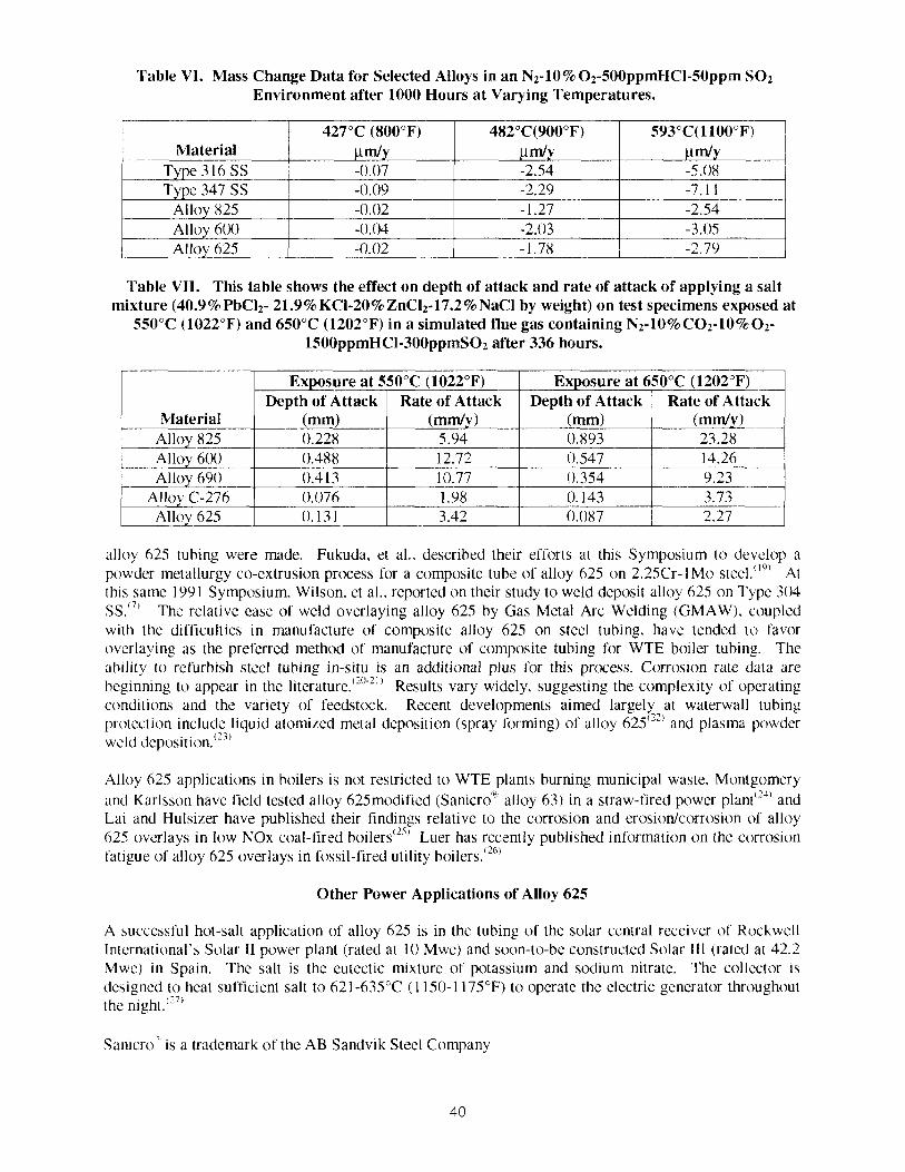
'I'able V1. Mass Change Data for Selected Alloys in an N2-10% 02-500ppmHC1-50ppm SO2 Environment after 1000 Hours at Varying Temperatures.
Material Type 3 16 SS Type 347 SS
All()y 825
I Allov 625 1 -0.02 1 -1.78 1 -2.74, 1
p d y -0.07
Alloy 6(X)
'l'able VI1. This table shows the effect on depth of attack and rate of attack of applying a salt mixture (40.9% PbCI2- 21.9 % KCI-20%ZnCI2-17.2% NaCl by weight) on test specimens exposed at
550°C (1022°F) and 650°C (1202°F) in a simulated flue gas containing N2-1O%CO2-10%02- 1500ppmHCI-300ppmS02 after 336 hours.
-0.09 -0.02
p d y -2.54
-0.04
p rnly -5.08
-2.29 - 1.27
Material Alloy 825 Alloy 60() Alloy 690
Alloy C-276
alloy 625 tubing were made. Fukuda, et al.. described their efforts at this Symposium to develop a powder rnelallurgy co-extrusion process for a composite tube of alloy 625 on 2.25Cr-1Mo steel.""' At this same 199 1 Symposium, Wilson. et al.. reported on their study to weld deposit alloy 625 on Type 304 SS."' The relative ease of weld overlaying alloy 625 by Gas Metal Arc Welding (GMAW), coupled with the difficulties in manufacture of composite alloy 625 on steel tubing, have tended lo favor overlaying as the preferred method of manufacture of composite tubing for WTE boiler tubing. The ability to refurbish steel tubing in-situ is an additional plus Sor this process. Corrosion rate data are beginning to appear in the literature.'"'"' Results vary widely. suggesting the complexity of operating conditions and the variety of feedstock. Recent developments aimed largely at waterwall tubing protection include liquid atomized metal deposition (spray forming) of alloy 625":' and plasma powder wcld deposition.'23'
-7.1 1 -2.54
-2.03
Alloy 625
Alloy 625 application? in boilers is not restricted to WTE plants burning municipal waste. Montgomery and Karlsson have field tested alloy 625modified (~anicro' \ l lo~ 63) in a straw-fired power plant'24' and Lai and Hulsizer have published their findings relative to the corrosion and erosionlcc~rrrrosion of alloy 625 overlays in low NOx coal-fired boilers'" Luer has recently published information on the corrosion fatigue of alloy 625 overlays in fossil-fired utility boiler^."^"
-3.05
Other Power Applications of Alloy 625
Exposure at 550°C (1022°F)
0.131
A successful hot-salt application of alloy 625 is in the tubins of the solar central receiver of Rockwell International's Solar I1 power plant (rated at 1 0 Mwe) and soon-to-be constructed Solar 111 (rated at 42.2 Mwe) in Spain. The salt is the eutectic mlxture of potassium and sodium nitrate. The collector 1s designed to heat sufficient salt to 621-635°C ( 1 150-1 175°F) lo operate the eleclric generator throughout the n~ght."~'
Exposure at 650°C (1202°F) Depth of Attack
(mm) 0.228 0.488 0.4 13 0.076
San~cro" is a trademark of the AB Sandvik Steel Company
Depth of Attack (mm) 0.893 0.547 0.354 0. 143
Rate of Attack ( m d y )
5.94 12.72 10.77 1 .98 3.42
Rate of Attack ( m d y ) 23.28 14.26 9.23 3.73
0.087 2.27
Automotive Applications for Alloy 625
Operating requirements for automotive power trains are rapidly becoming increasingly severe. Higher temperatures and tighter emission requirements, along with extended warranties and governmental demands for increased gas mileage, are rending uadtional exhaust system materials marginally acceptable and, increasingly more common, unacceptable for a growing number of engine platforms. Within the exhaust system, alloy 625 has established a reputation as the ultimate material for the bellows portion of flexible couplings and exhaust gas recirculation (EGR) tubin4. Papers describing the perfortnance of alloy 625 in this application began appearing in the mid 1990~.'-*-'~'
Flexible Couplings and EGR Tubing
Flexible couplings for automotive exhaust systems are a very demanding application because they are susceptible to attack by a wide range of corrosion mechanisms encountered in everyday driving. particularly road deicing salts. Depending on the design and location in the exhaust system. potential failure mechanisms include fatigue. corrosion fatigue. oxidation. hot-salt ccxrosion. stress-corrosion craclung, pitting and general corrosion. Similar to the flexible coupling. the EGR tubing may also be exposed to fatigue and corrosion. It is important to recognize the potential for failure and select the most cost-effective materials. The trend towards higher temperatures and leak-free system warranties to 160,000 km (100,000 miles) or ten years makes a strong case for high-performance alloys, such as alloy 625, to replace traditional alloys fix these key components.
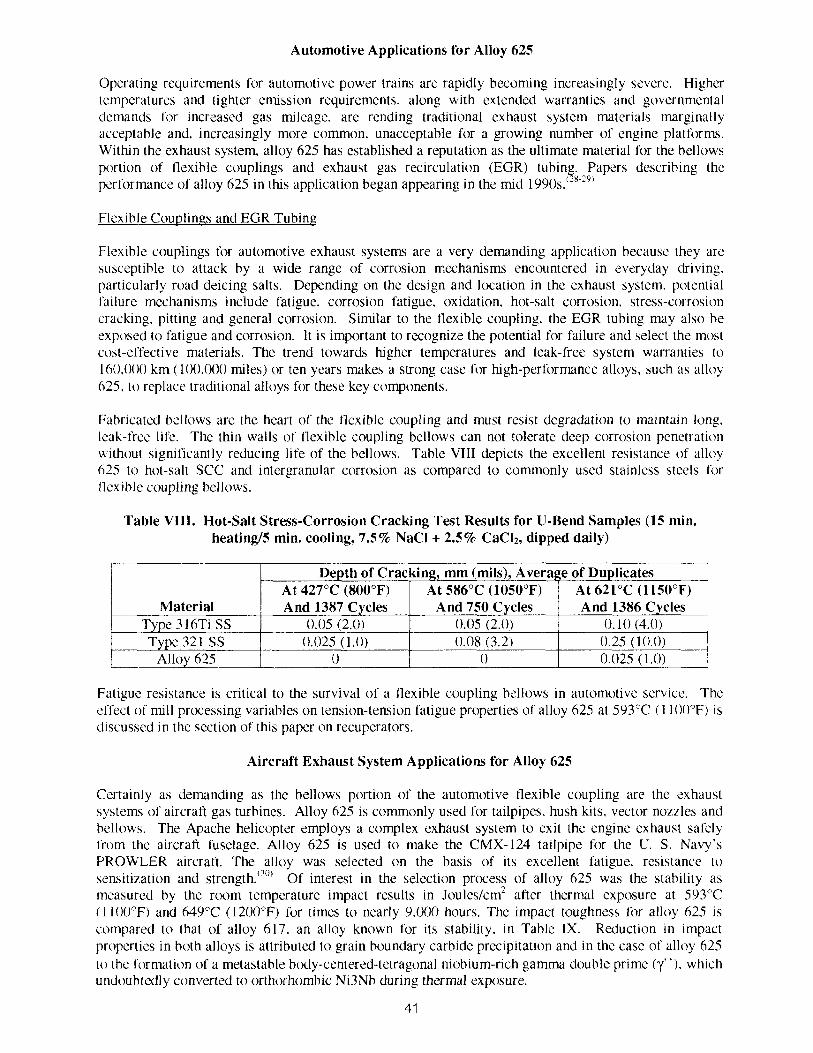
Fabricated bellows are the heart of the tlex~ble coupllng and must resist degradation to malntaln long. leak-free life. The thln walls of flexlble coupling bellows can not tolerate deep corrosion penaratlon w~thout sign~ficantly reduclng life of the bellows. Table VIII deplcts the excellent resistance of alloy 625 to hot-salt SCC and lntergranular corrosion as compared to commonly used stainless steels for flexlble coupling bellows.
Table VIII. Hot-Salt Stress-Corrosion Cracking Test Results for U-Bend Samples (15 min. heatin@ min. cooling, 7.5% NaCl + 2.5% CaC12, dipped daily)
Fat~gue resistance is critical to the survival of a flexible coupling bellows In automotive servlce. The effect of rmll prcxessing variables on tension-tension fatigue properties of alloy 625 at 593°C (1 100°F) is discussed in the section of this paper on recuperators.
Material Type 3 1 6Ti SS Type 32 1 SS
Alloy 625
Aircraft Exhaust System Applications for Alloy 625
Certainly as demandmg as the bellows portion of the automotive flexible coupling are the exhaust systems of aircraft gas turbines. Alloy 625 is commonly used for tailpipes. hush kits, vector nozzles and bellows. The Apache helicopter employs a complex exhaust system to exit the engine exhaust safely from the aircraft fuselage. Alloy 625 is u s d to make the CMX-124 tailpipe for the U. S. Navy's PROWLER aircraft. The alloy was selected on the basis of its excellent fatigue. resistance to sensitization and strength.'30' Of interest in the selection process of alloy 625 was the stability as measured by the room temperature impact results in ~oules/cm' after thermal exposure at 593°C ( 1 100°F) and 649°C (1200°F) fbr times to nearly 9.0()0 hours. The impact toughness for alloy 625 is compared to that of alloy 617. an alloy known for its stability. in Table IX. Reduction in impact properties in both alloys is attributed to grain boundary carbide precipitation and in the case of alloy 625 to the formation of a metastable body-centered-tetragonal niobium-rich gamma double prime (y"), which undoubtedly converted to orthorhombic Ni3Nb during thermal exposure.
of Duplicates At 621°C (1150°F) And 1386 Cycles
0.10 (4.0) 0.25 (10.0) 0.025 ( 1 .O)
Depth of Cracking, mm (mils), Average At 427°C (800°F) And 1387 Cycles
0.05 (2.0) 0.025 (1 .O)
0
At 586°C (1050°F) And 750 Cycles
0.0s (2.0) 0.08 (1.2)
(1
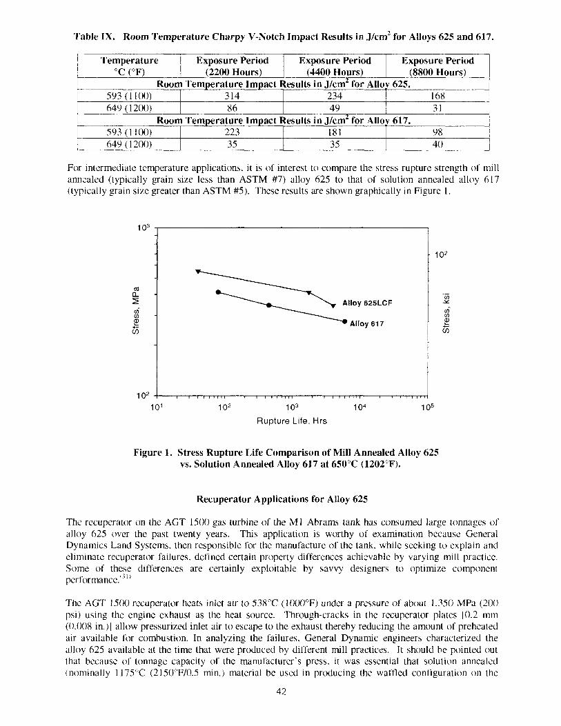
'I'able IX. Room Temperature Charpy V-Notch Impact Results in .l/cm2 for Alloys 625 and 617.
I Temperature I Exposure Period I Exposure Period I Exposure Peritd / "C ( O F )
For intermediate temperature applications, it is of interest to compare the stress rupture strength of mill anncaled (typically grain s i x less than ASTM #7) alloy 625 to that of solution annealed alloy 617 (typically grain s i x greater than ASTM #5). These results are shown graphically in Figure I .
593 ( 1 lo()) 649 ( 1 200)
- lo2
L
. - V)
Alloy 625LCF Y
Alloy 61 7
Room Temperature Impact Results in ~ / c m ' for Alloy 625. (2200 Hours)
1 02 10' I 02 1 o3 1 o4 I o5
Rupture Life, Hrs
(4400 Hours) (8800 Hours) I 314 8 6
Figure 1. Stress Rupture Life Comparison of Mill Annealed Alloy 625 vs. Solution Annealed Alloy 617 at 650°C (1202°F).
Room Temperature Impact Results in ~ l c m ' for Alloy 617.
Recuperator Applications for Alloy 625
234 49
The rccuperator on the ACT 1500 gas turbine of the MI Abrams lank has consumed large tonnages of alloy 625 over the past twenty years. Thls application is worthy of examination because General Dynamics Land Systems. then responsible for the manufacture of the tank, while seeking to explain and eliminate recuperator failures. defined certain property differences achievable by varying mill practice. S o ~ n e of these differences are certainly exploitable by savvy designers to optimize component performance.'7"
168 3 1
5% i 1 lo( ) )
Thc ACT 1500 recuperator heats Inlet alr to 538°C (1000°F) under a pressure of about 1,350 MPa (20() PSI) u w g the engine exhaust as the heat source. Through-cracks In the recuperator plates 10.2 rnm (O.OU8 in.)] allow pressur~xd inlet air to escape to the exhaust thereby reduclng the amount of preheated alr ava~lable for combustion. In a n a l y ~ ~ n g the lallures. General Dynamc engineers charactenmi the alloy 625 available at the tlme that were produced by different mill practices. It should be polnted out that because of tonnage capacity of the manufacturer's press, it was essential that solution annealed (nominally 1175°C (215O0F/O.5 mn.) material be used in producmg the waffled conliguration on the
227 181 98

plates. However. vacuum melted, milled annealed (nominally 1065°C (195OCF/0.5 mln.) alloy 625 per AMS 5879 was also charactenmi by General Dynamcs. The tensile data are presented in Table X and tension-tension axial fatigue data In Table XI.
These General Dynamic5 data show a number of distlnct d~ffercnccs between mll pracllces. Notably among them 1s the fact that vacuum melting reduces total res~duc content. Ttus in turn. a1d5 tensile duct~lity as does solut~on annealmg In contrast to lower temperature mlll annealing. It also appear5 to cnhance low cycle fatigue and s t res rupture life at 593°C ( I IOU°F) when used in conjunction with m~l l annealing and control of composmon. Examnmg the fatigue lives at 593cC ( I 100°F) after aglng at 704°C (13OOoF)/30O hours suggests that the tugh cycle fat~gue properms tend to converge as aglng equall/e\ the strength levels of the d~fferent mill practices.
Grubb reported at the 4'h Symposium that when using 0.9 mm (0.035 in.) sheet. no difference was Sound between material meeting the compositional limits of AMS 5599 and that of AMS 5879 when both alloys were prtxessed to similar grain size and strength."" However, the jury may still be out regarding inclusion content in thin sheet and strip resulting fiom the mill processing differences between the two specifications. since the study of General Dynamics. which used thinner 0.2 mm (0.008 in.) sheet. varied both prcxluct inclusion content and annealing practice in their comparative test. Results reported by Smith and Yates did find a dffercnce in 0.2 mm (0.008 in.) sheet properties when testing air or AOD + ESR melted material (up to 0.42% total inclusion content) vs. VIM + ESR (0.06% total inclusion content) ~hee t . '~" A literature search correlating inclusions, fatigue and nickel-base alloys lbund 108 citation^. It remains for future research to precisely correlate mill practice variables and fatigue of alloy 625 sheet.
'Table X. Tensile Properties of Alloy 625 as Defined by Mill Practice.
Room Temperature Tensile Properties
L
ASTM Grain S i x Total Residue Percentage
Welding of Austenitic Stainless Steels
Property 0.2% Y.S.. MPa (ksi)
U.T.S., MPa (ksi)
593°C (1100°F) Tensile Properties
The excellent corrosion resistance of alloy 625 is increasingly used to solve welding problems encountered in some of the austenitic stainless steels.'") When the 34%) molybdenum austenitic stainless steels are welded with matching filler metals. the welds often suffer from accelerated corrosion due to molybdenum segregation. During solidification, the welds cool too rapidly for the molybdenum to be distributed uniformly. resulting in dendrite cores that are considerably lower. and the interdendritic region markedly higher. in molybdenum. Thls often results in preferential attack of the dendritic centers. and has heen a particular problem in pulp and paper manufacturing environments. The problem has been solved by using alloy 625 filler metal which raises the molybdenum content of the diluted weld metal to such a level that the pitting and crevice corrosion resistance of the weld metal is equal or better than the austenitic stainless steel base metal.
AOD + ESR Mill Annealed Per AMS 5599
507 (73.5) 95 1 (1 38,O)
Air Melted Solution Annealed
Per AMS 5599 339 (49.1 )
747 (108.4)
5 0.42
0.2% Y.S., MPa (ksi) 244 (35.4)
Table XI. Tension-Tension Axial Fatigue Results as Defined by Mill Practice.
VIM + ESR Mill Annealed Per AMS 5879
467(67.8) 846 (122.7)
9 ----
360 (52.2)
8.5 0.06
349 (50.6) 712 (103.3) 805 (1 16.8) U.T.S.. MPa (ksi) 563 (8 1.6)

Tension-Tension* Axial Fatigue at 593°C ( 1 100°F) - Cycles to Failure As-Received Condition
Maximum Stress
MPa ( h i )
*Minimum Tension Stress is 34.5 MPa (5,000 psi) Test Frequency is 60 HL
L
62 1 (90) 552 (80) 483 (70) 414 (60)
Conclusions
Air Melted Solution Annealed
Per AMS 5 5 9
Seldom docs an alloy become a standard material of construction in a wide variety of industrial applications. Alloy 625. however, is such an alloy. Ever since its introduction in the early 1960s. the alloy has proven to be a valuable and versatile material that is able to solve a wide variety of design and applicatjon problems. Its ability to resist low temperature aggressive corrosion environments as well as hoslile high temperature environments with a h g h level of strength has enabled it to be specified frequently in a &verse cross section of industries. In addition to the original goal of a material for main steam-line piping. it has been used extensively in the aerospace. automobile. chemical prcxessing. oil prtxluction. oil refining. marine, waste treatment, pulp & paper and power industries. As an indication of its versatility. slight modifications in composition and mill practice have dramatically increased the fatigue life of thin sheet. thereby increasing the design capabilities in critical turbine components. The excellent weldability of the alloy, and its ability to accommodate dilution from other compositions. has often led to the specification of alloy 625 tiller metals for dissimilar welding. It seems reasonable to predict that alloy 625 as weld overlayed or co-extruded as either waterwall or superheater tubing will play a major role in the future worldwide growth of municipal WTE and refuse-derived-fuel (RDF) plants.
758 ( I 10)
Aged at 704°C (1300°F)/300 Hours Prior to Fatigue Testing 758 ( 1 10) ---- 1.592
Failed on Loadmg 5,924 15,966
138,109
Thus. while alloy 625 has had an impressive past and is enjoying a significant presence, there 1s the pronlise of an even more awesome future.
AOD + ESR Mill Annealed Per AMS 5599
References
VIM + ESR Mill Annealed Per ANIS 5879
10.672 20(),0()0
9,950,000 ----
H. L. Eiselstein and D. J. Tillack, "The Invention and Definition of Alloy 625," Superalloys 7 18. 625 and Various Derivatives, ed. E. A. Loria (Warrendale. PA. TMS. 1991. 1-14. S. Floreen. G. E. Fuchs and W. J. Yang. "The Metallurgy of Alloy 625." Superalloys 718. 625. 706 and Various Derivatives. ed. E. A. Loria (Warrendale, PA, TMS. 1994. 13-38. INCONEL alloy 625 Bulletin, Published by Inco Alloys International. Bulletin 193. Huntington, WV. 1998. P. Ganesan, C. M. Renteria and J. R. Crum. "Versatile Corrosion Resistance of Inconel AIloy 625 in Various Aqueous and Chemical Processing Environments." Su~erallovs 718, 625 and Various Derivatives, ecl. E. A. Loria (Warrendale, PA. TMS. 199 1. 663-680. G. D. Smith. S. D. Kiser. J. R. Crum and C. S. Tassen, "Nickel Base Alloys Improve Corrosion Resistance." The International Journal of Hydrocarbon engineer in^, May 1999. A. L. Moran. W. A. Palko. C. J. Madden and P. Kelley. "Spray Formed Alloy 625 Tubulars." Sunerallovs 718. 625 and Various Derivatives. ed. E. A. Loria (Warrcndale. PA. TMS. 1991. 843- 85( 1.
6.939 ---- 14.500
1,900.()00 > IO.OOO.000
----
5.455
7. 1. L. W. Wilson. R. G. Gourley. R. M. Walkosak and G. J. Bruck. "The Effect of Heat Input on Microstructure and Crachng in Alloy 625 Weld Overlays." Superallo~s 718, 625 and Various Derivatives. ed. E. A. Loria (Warrendale. PA, TMS. 199 1. 735-748.
8. H. H. Krause. "High Temperature Corrosion Problems in Waste Incineration Systems." Journal of Materials for Energy Systems. 7, 1986. 322-332.
9. M. H. Brown. W. B. Delong and J. R. Auld. "Corrosion by Chlorine and Hydrogen Chloride at High Temperatures." Journal of Industrial Engineering and Chemistry, 39. 1947, 839-844.
10. D. E. Fluck, G. Y. Lai. M. F. Rothman. "Selection of Materials for Combustion Environments Associated with Waste Incineration." CORROSION/85, Paper No. 333. NACE. International. Houston, TX, 1989.
I I . G. D. Smith. P. Ganesan and L. E. Shoemaker. "The Effects of Environmental Excursions within the Wastc Incinerator on Nickel-Containing Alloy Performance." CORROSION/93. Paper No. 280. NACE International. Houston. TX. 1993.
12. B. A. Baker and N. C. Farr. "Corrosion Resistant Features of High Nickel Alloys in Relation to Waste Incineration Applications." Welding PrtKiucts Co. Seminar. Stuggart. Germany. October. 1999.
13. M. Spiegel. "Corrosion of 2.25Cr-1Mo and Alloy 625 Beneath a Molten KCI-ZnC12 Salt Mixture," Prcxeedings of EUROCORR/99 Congress. FFCE, Achen. 1999.
14. M. Norell and P. Andersson. "Field Test of Watcrwall Corrosion in a CFB Waste Incinerator." CORROSIONl99. Paper No. 236, NACE International. Houston, TX, 1999.
15. K. Kawahara. N. Orita. M. Nakamura. S. Ayukawa and T. Hosoda. "Application of Corrosio- Resistant Superheater Tubing for a 5CW°C 100 ~gflcm' High Efficiency Waste-to-Energy Plant." CORROSION/99. Paper No. 9 1. NACE International. Houston. TX. 1999.
16. T. Matsui. h. Takizawa. S. Wahta, Y. Kawahara and T. Hoscda. "Development of Ni-Cr-Mo Alloy for the Superheater Tube Applications." CORROSION/200(), Paper No. 262. NACE International, Houston. TX. 20iX).
17. L. Nylof; E. Haggblom, "Corrosion of'Experimental Superheater Alloys in Waste Fuel Combustion." CORROSIONl97. Paper No. 154. NACE International, Houston. TX. 1997.
18. Y. Kawahara. T. Hoscxla. K. Takahash. Y. Nakagawa and T Mizuko, "Demonstration Test of New Corrosion-Resistant Superheater Tubings in a High Efficiency Waste-ttrEnergy Plant." CORROSION/2000. Paper No. 265. NACE International. Houston, TX. 2000.
19. T. Fukuda. Y. Ohash. M. Nakanishi. M. Nishiguchi. M. Ueda. S. Azuma and J. Kikuchi. "Development of a Production Technique for P/M Alloy 625 Clad Low Alloy Steel Pipe." Superalloys 7 18. 625 and Various Derivatives. ed. E. A. Loria (Warrendale. PA, TMS. 199 I . 793- 802.
20. G. Sorrel. "The Role of Chlorine in High Temperature Corrosion in Waste-to-Energy Plants." Materials at High Temperature, 14. No. 3. 1997. 137- 150.
21. B. A. Baker. S. D. Kiser and C. Cooper. "Welding Products for Extension 01' Waterwall and Superheater Tubing Life in Waste-to-Energy Plants," Welding Products Co. Seminar, Stuggart. Germany, October. 1999.
22. A. Wilson. U. Forsberg and J. Noble. "Experience of Composite Tubes in Municipal Waste Incinerators," CORROSION/97, Paper No. 153. NACE International, Houston. TX. 1997.
23. K. Kawahara. M. Nakamura. H. Tsuboi and K. Yukawa. "Evaluation of New Corrosion-Resistant Superheater Tubing in High Efficiency Waste-To-Energy Plants," Corrosion. 54. No. 7. 1998, 576- 5x9.
24. M. Montgomery and E. Maahn, "Laboratory Study of High Temperature Corrosion in Straw-Fired Power Plants," EurtCorr97. Vol.11. Trondheim, 1997. 41 -46.
25. G. Lai and P. Hulsizer. "Corrosion and Erosion/Corrosion Protection by Modern Weld Overlays i n Low NOx Coal-Fired Boilers."
26. K. Luer. "Cwrosion Fatigue of Alloy 625 Weld Claddings Exposed t., Combustion Environments." Advanced Materials & Prcxesses. February. 2000, 24-25.
27. Solar Power Towers, SOLTEC Data Sheet. M7611/94/rs. Published by Rtxketdyne Division, Rtxkwell International, Canoga Park, CA, 1994.
28. G. D. Smith. J. R. Crum and R. A. Smith. "Characterization of INCONEL alloy 625LCF Flexible Coupling Performance in Automotive Applications." Presentation at ASM Materials Week. Cincinnati, OH. October 6-10. 1996.

29. G. D. Smith, J. R. Crum and H. L. Flower. "High Temperature Corrosion Performance of Automotive Coupling Alloys," CORROSIONl98. Paper No. 742. NACE International. Houston. TX. 1998.
30. B. A. Baker and G. D. Smith, "Perfimmnce of Nickel Alloys for the Tailpipe of the PROWLER Aircraft." Presentation at ASM Materials Week. Cincinnati. OH. October 6-10. 1996.
31. S. P. Martin and H. E. Schuneman, "ACT 1500 Recuperator Failure Analysis." Internal Report of General Dynamics Land Systems Division, October. 1989.
32. J . F. Gruhb, "Fatigue Resistance of Alloy 625 Sheet." Sunerallovs 718, 625, 706 and Various Derivatives. ecl. E. A. Loria (Warrendale. PA. TMS. 1997. 629-638.
33. G. D. Smith and D. H. Yates. "Optimization of the Fatigue Properties of Inconel alloy 625." Superallovs 718. 625 and Various Derivatives. ed. E. A. Loria (Warrendale. PA. TMS. 1991. 509- 5 18.
34. A. Garner. "Corrosion of High Alloy Austenitic Stainless Steel Weldments in Oxidizing Environments." Materials Performance. August. 1982, 9- 14.


![[XLS] · Web view1 265 263 99.245279999999994 2 625 614 98.24 3 425 416 97.882350000000002 4 625 600 96 5 325 312 96 6 625 596 95.36 7 625 585 93.6 8 625 584 93.44 9 625 579 92.64](https://static.fdocuments.us/doc/165x107/5ab38e447f8b9a6b468e79ff/xls-view1-265-263-99245279999999994-2-625-614-9824-3-425-416-97882350000000002.jpg)