Allegro PCB Editor og OrCAD PCB Designer …€¦ODB++ o Developed by Valor Computerized Systems Ltd...
22
Output formats Its all about communication, design for fabrication/assembly and output generation! OLE EJLERSEN CTO, ansat siden 1995 [email protected] www.linkedin.com/in/ejlersen
Transcript of Allegro PCB Editor og OrCAD PCB Designer …€¦ODB++ o Developed by Valor Computerized Systems Ltd...
Output formatsIts all about communication, design for fabrication/assembly and output generation!
OLE EJLERSENCTO, ansat siden 1995
www.linkedin.com/in/ejlersen

©2018 Nordcad AS
Hvem er Nordcad AS?
Mål
• Tilby våre brukere den beste teknologiske plattform til elektronikkdesign.
• Øke brukernes kompetansenivå som resulterer i en rask og effektiv designfase.
Misjon
• Være den største og mest seriøse leverandør av verktøy til elektronikkdesign i Norge, Danmark, i Grønland, på Island og på Færøyene.
Visjon
• Bidra til at norske og danske elektronikkvirksomheter får et forsprang i konkurransen på det globale marked.
• Gratis programvare og utdannelsesmateriale til alle studenter slik at industrien får kvalifisert arbeidskraft.
Utdannelse
Rådgiving om EDAsoftware
Seminarer og
workshops
Telefon support
Konsulent
2

©2018 Nordcad AS
Gratis telefon support (for kunder med gyldig vedlikeholdsaftale)
Kontakt via telefon: +47 21 55 28 28hverdager 9 – 16 (fredag 9 – 15)
Eller mail: [email protected] Vi svarer i juletider, nyttår og sommerferien!
En lett vei til hjelp og veiledning i bruken av verktøyene og teknologien
RASMUS SØGAARD JACOBSENIT Specialist, ansat siden 2016
o Programmering
o Integration
o Installation
OLE EJLERSENCTO, ansat siden 1995
o PCB Design
o Komponentstyring
o Design processer
o Programmering i Skill
SØREN JUL CHRISTIANSENSignal Integrity Manager, ansat siden 2008
o Design metodik for elektronik
o Verifikation af digital elektronik
o Constraint styret PCB design
ANDERS MEDELBYE PEDERSENSimulation manager, ansat siden 2015
o Simulering i PSpice
o Full board simulering i PSpice
o Programmering i C++
Vi bruker Teamviewer for å kunne gi deg den beste mulige fjern-support.
MARTIN LANGE NONBOESupport & uddannelse, ansat siden 2017
o Diagramtegning
o PCB Design
o Komponentstyring
Service og support team
3
©2018 Nordcad AS
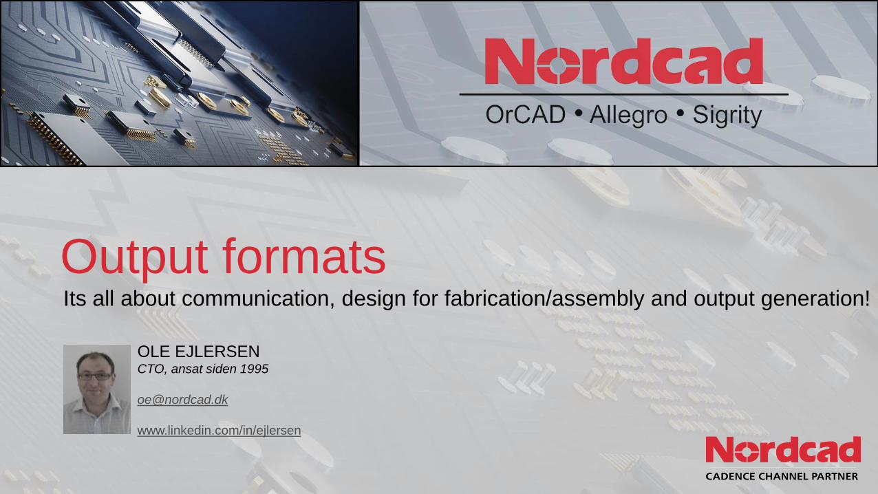
Verdens største leverandør
Nordcad Systems A/S Awarded January 2014: ”Technical Partner”
Nordcad Systems A/S Awarded January 2016: ”Business Partner”
16 GLOBAL DEVELOPMENT CENTERS
$750MR&D INVESTMENT
IN 2017
1500+ PATENTS
WORLDWIDE
3,300RESEARCH AND DEVELOPMENT
ENGINEERS
1300FIELD APPLICATION
ENGINEERS
Hvem er Cadence
4
©2018 Nordcad AS
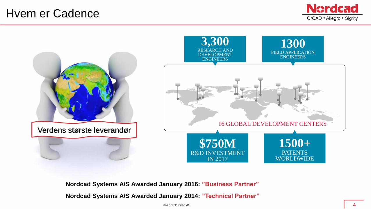
OrCAD produkter
5
©2018 Nordcad AS
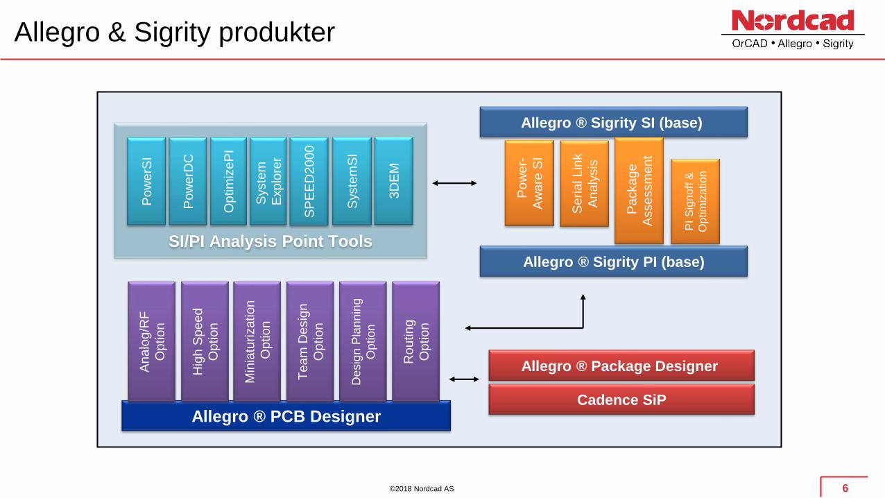
Allegro & Sigrity produkter
6
Allegro ® Package Designer
Allegro ® Sigrity SI (base)
SI/PI Analysis Point Tools
Cadence SiP
Allegro ® Sigrity PI (base)
Allegro ® PCB Designer
Te
am
De
sig
n
Op
tio
n
Min
iatu
rization
Op
tio
n
Hig
h S
pe
ed
Op
tio
n
An
alo
g/R
F
Op
tio
n
Desig
n P
lannin
g
Option
Ro
utin
g
Op
tio
n
Po
we
rSI
Po
we
rDC
Syste
m
Exp
lore
r
Op
tim
ize
PI
SP
EE
D2
00
0
PI
Sig
no
ff &
Op
tim
iza
tio
n
Pa
cka
ge
Asse
ssm
en
t
Se
ria
l L
ink
An
aly
sis
Po
we
r-
Aw
are
SI
Syste
mS
I
3D
EM
©2018 Nordcad AS
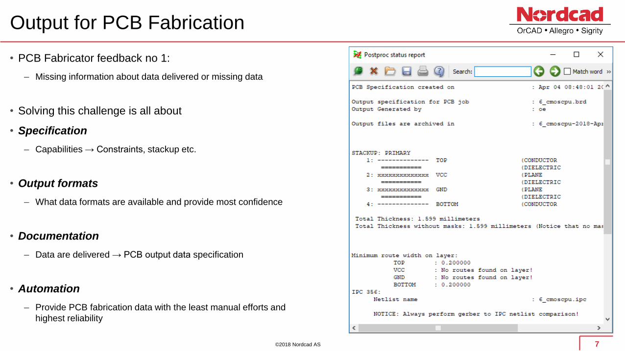
Output for PCB Fabrication
• PCB Fabricator feedback no 1:
– Missing information about data delivered or missing data
• Solving this challenge is all about
• Specification
– Capabilities → Constraints, stackup etc.
• Output formats
– What data formats are available and provide most confidence
• Documentation
– Data are delivered → PCB output data specification
• Automation
– Provide PCB fabrication data with the least manual efforts and
highest reliability
7

©2018 Nordcad AS
Specification / Design for production/manufacturing
• Building design intent doesn’t cover everything!
• Thinking manufacturing and assembly from the start
– Understanding capabilities and tolerance chains
– Mapping capabilities to design rules
– Designing for manufacturing and assembly yields lower cost and
higher quality
• Fixing manufacturability in the end of the design cycle is
time intensive and expensive
• Communicate, communicate and communicate
8
Logic
Schematics
Placement
Routing
Mfg Prep
Internal check
FABRICATION
4 to 48
hours

©2018 Nordcad AS
Examples
9
• These are independent of output format
• Always look at fab capabilities
– Hole sizes
– Line widths
– Spacing/gap
– Tolerances (impedance, dimensions, holes etc.)
– Aspect ratio
• Align your board constraints with these capabilities!
• Remember that cost and capabilities are related
• Using different fab for prototypes and production?
– Is that reliable? How can you be sure the results are the same
– Not the case for MACAOS according to Helge @Elprint!
• Examples
– Elprint: https://www.elprint.no/products/pcb/capabilities
– NCAB: https://www.ncabgroup.com/capability/
• Electrical constraints does not lead automaticaly lead to
manufacturing
– Might work at 0.02mm width but can’t be produced or is costly
• Not checking and setting up for fabrication can lead to lots
of rework
– Redesign
– Ripup
– Placement
Table from https://www.elprint.no/products/pcb/capabilities

©2018 Nordcad AS
Output formats
IPC2581
o Open, neutral, global vendor independent standard. Xml based data format. (www.ipc2581.com)
o Cover fabrication and assembly
ODB++
o Developed by Valor Computerized Systems Ltd in 1995, today owned by Mentor Graphics
MACAOS .MEI format
o Data format for fast production with Elprint (www.macaos.no / www.elprint.no)
o Single click output generation available from Nordcad and Elprint ☺
Gerber, Excellon drill/route/milling, pick and place, PDF, IPC356 etc.
o A ”large” collection of individual text based files
Others, why bother since the above are more or less industry standards?
All production interfaces are included with OrCAD/Allegro PCB solutions
10

©2018 Nordcad AS
Gerber, Excellon, IPC356, etc.
We’ve all tried it, been there, done that! I guess we’ve all experienced issues!
• Supported to some extent by all ECAD tools
• Good old well known format (industry standard)
• Has a convenience factor, we all know the format. Can be somehow verified in any Gerber viewer
• Collection of files that designer has to create, collect, explain and ship to manufacturer
• Many pitfalls
– File formats (integer & decimal places, leading/trailing zeroes)
– Verification
– Creating a description (PCB Specification)
– Forgot to create file or send file
– Many files involved: gerber (copper, soldermask, pastemask, silkscreen), plated and non-plated drill files (slots, blind/buried, counter-bore/sink,
backdrilling etc.), contour files, milling files, pick and place etc.
• Enhanced to Gerber X2 but not widely supported or used. Yet another vendor dependent format being pushed by
Ucamco (format owner)
11
©2018 Nordcad AS
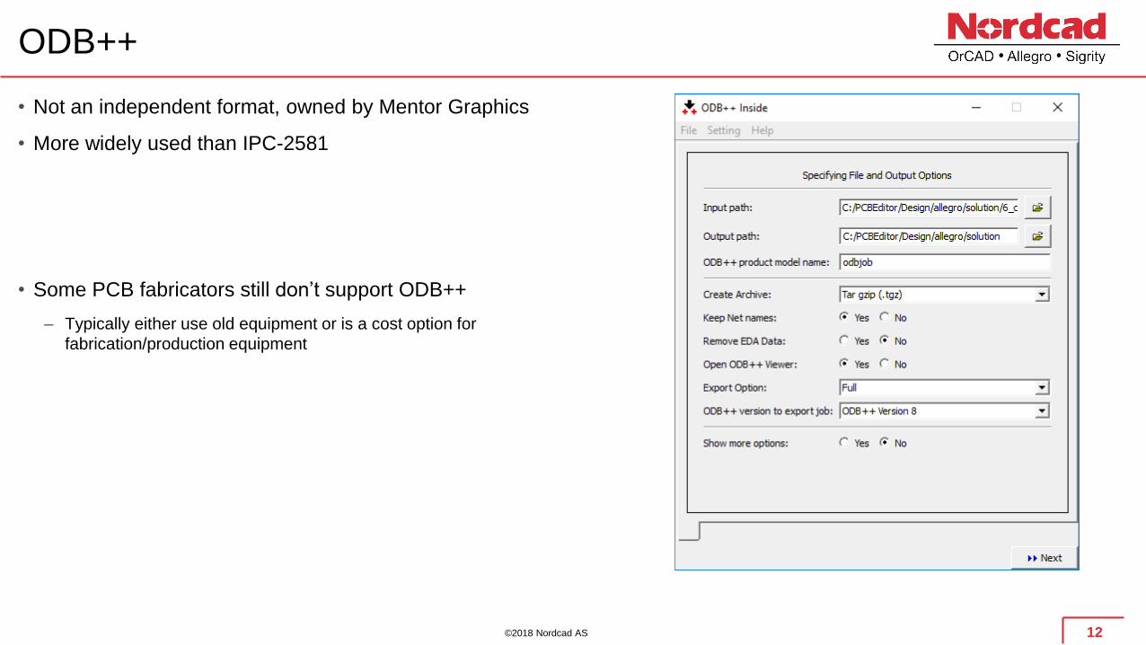
ODB++
• Not an independent format, owned by Mentor Graphics
• More widely used than IPC-2581
• Some PCB fabricators still don’t support ODB++
– Typically either use old equipment or is a cost option for
fabrication/production equipment
12
©2018 Nordcad AS
IPC2581
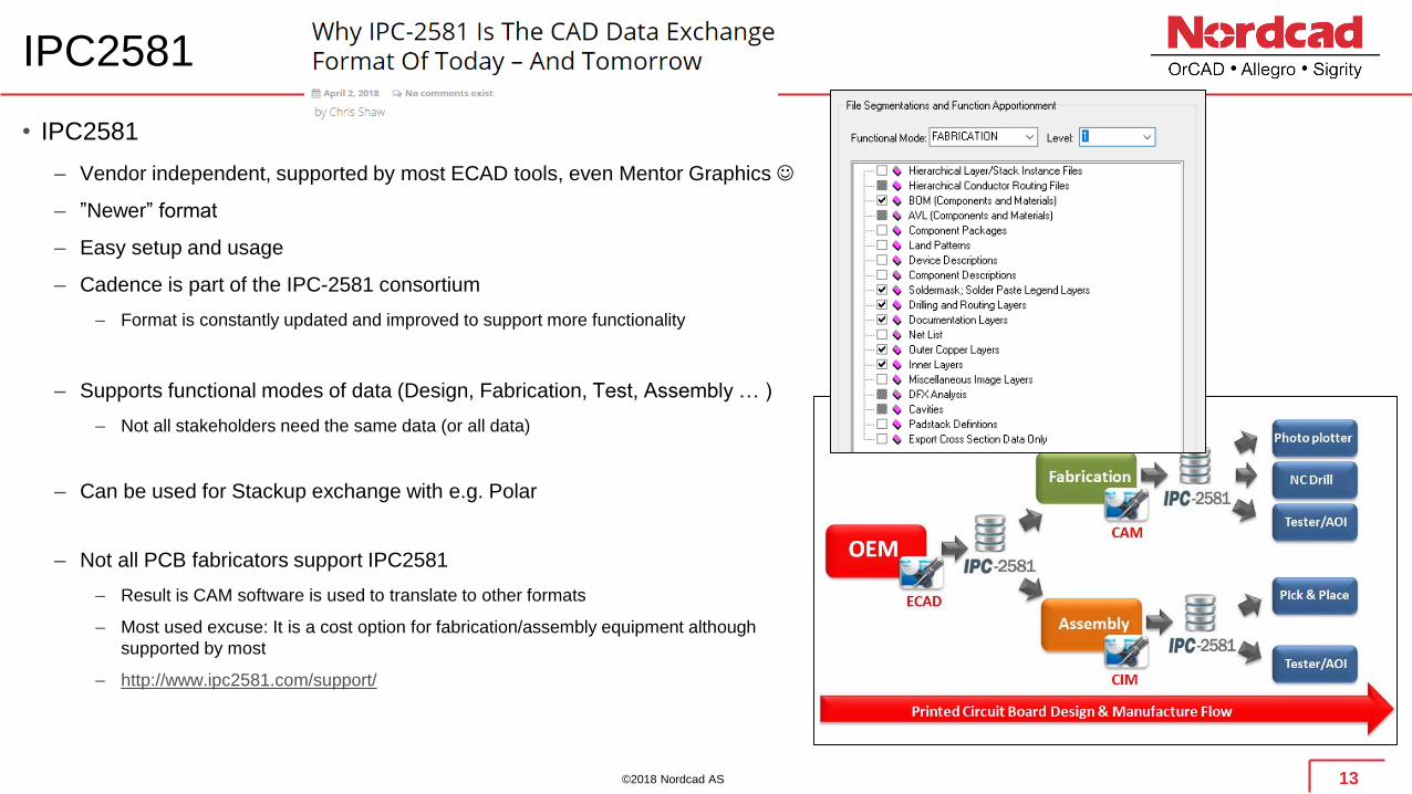
• IPC2581
– Vendor independent, supported by most ECAD tools, even Mentor Graphics ☺
– ”Newer” format
– Easy setup and usage
– Cadence is part of the IPC-2581 consortium
– Format is constantly updated and improved to support more functionality
– Supports functional modes of data (Design, Fabrication, Test, Assembly … )
– Not all stakeholders need the same data (or all data)
– Can be used for Stackup exchange with e.g. Polar
– Not all PCB fabricators support IPC2581
– Result is CAM software is used to translate to other formats
– Most used excuse: It is a cost option for fabrication/assembly equipment although
supported by most
– http://www.ipc2581.com/support/
13
©2018 Nordcad AS
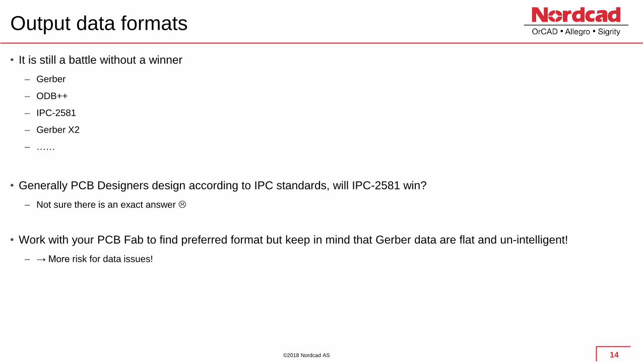
Output data formats
• It is still a battle without a winner
– Gerber
– ODB++
– IPC-2581
– Gerber X2
– ……
• Generally PCB Designers design according to IPC standards, will IPC-2581 win?
– Not sure there is an exact answer
• Work with your PCB Fab to find preferred format but keep in mind that Gerber data are flat and un-intelligent!
– → More risk for data issues!
14
©2018 Nordcad AS
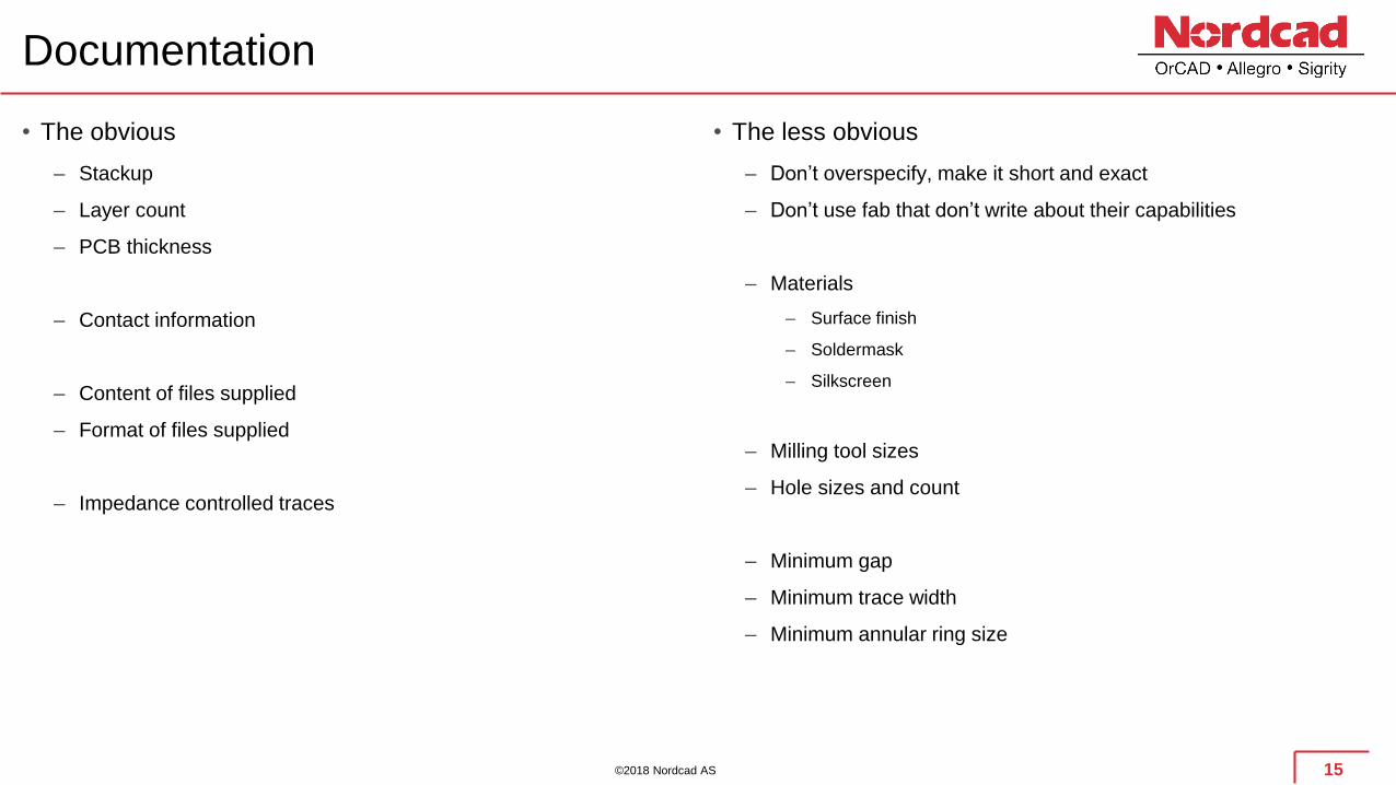
Documentation
15
• The obvious
– Stackup
– Layer count
– PCB thickness
– Contact information
– Content of files supplied
– Format of files supplied
– Impedance controlled traces
• The less obvious
– Don’t overspecify, make it short and exact
– Don’t use fab that don’t write about their capabilities
– Materials
– Surface finish
– Soldermask
– Silkscreen
– Milling tool sizes
– Hole sizes and count
– Minimum gap
– Minimum trace width
– Minimum annular ring size

©2018 Nordcad AS
Examples
• Do specify
– Stackup (final thickness)
– Materials/colors for soldermask and silkscreen
– Surface finish
– Contour details
– Plated and non-plated holes separately
– Content of files supplied
– Require data vs. IPC-356 netlist verification when using non-
intelligent format
16
©2018 Nordcad AS
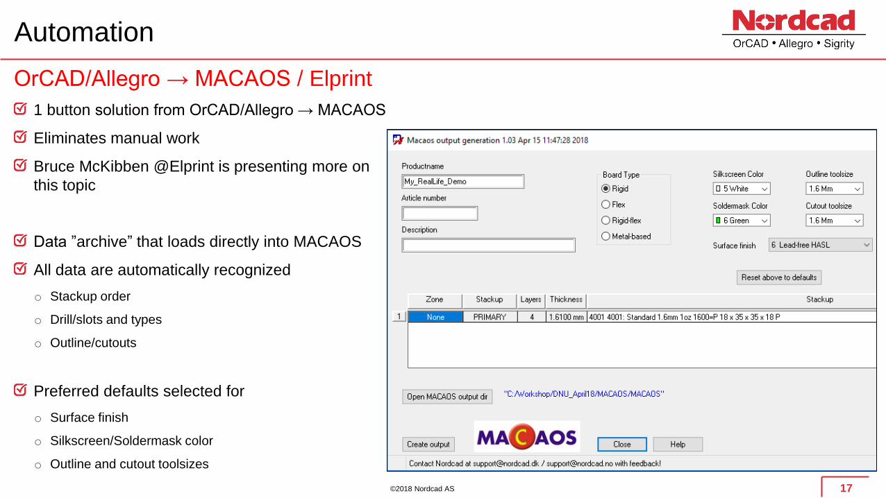
Automation
1 button solution from OrCAD/Allegro → MACAOS
Eliminates manual work
Bruce McKibben @Elprint is presenting more on
this topic
Data ”archive” that loads directly into MACAOS
All data are automatically recognized
o Stackup order
o Drill/slots and types
o Outline/cutouts
Preferred defaults selected for
o Surface finish
o Silkscreen/Soldermask color
o Outline and cutout toolsizes
17
OrCAD/Allegro → MACAOS / Elprint

©2018 Nordcad AS
MACAOS reads and understands data
18

©2018 Nordcad AS 19
OrCAD/Allegro → MACAOS demo ☺

©2018 Nordcad AS
Automation for Gerber
o Generate all data
o Zip data
o Create readme file with specification (can be customized)
More reliable and robust data exchange if gerbers are used
o Ensure all data are generated
o Automatically create PCB specification
o More specification is needed (surface finish etc.) if not customized
20
General purpose post processing utility with OrCAD/Allegro
©2018 Nordcad AS
The final comments/suggestions
• Reviewing production data before sending them into a CAM tool
– Sanity check in 3rd party tool
• Checking Gerbers / ODB++ or IPC2581
– Importing output manufacturing files and checking if they look ”alright”?
– Do they import OK and are they all present?
• IPC netlist check
– Do production files represent the correct connectivity?
– Open and shorts that aren’t expected?
• Making sure specification includes all important data
– Number one feedback from manufacturers is missing specification or lack of information
• New to PCB Design?
– Communicate with PCB Fabricator and EDA software vendor
– Visit PCB fab to walk over complete production process
• Getting to the next level
– There are PCB Designer courses CID and CID+ (http://www.ipc.org/ContentPage.aspx?pageid=Designer-Certification )
– Requires 2 years working experience with PCB Design
21
©2018 Nordcad AS
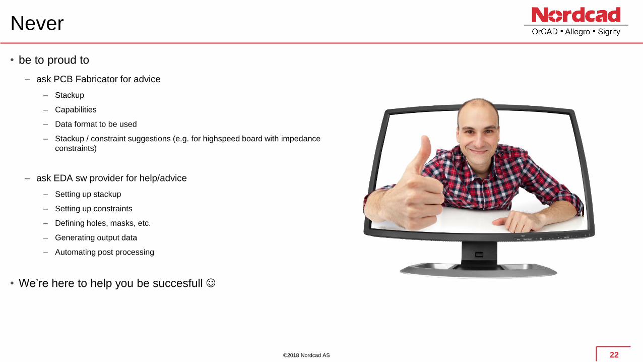
Never
• be to proud to
– ask PCB Fabricator for advice
– Stackup
– Capabilities
– Data format to be used
– Stackup / constraint suggestions (e.g. for highspeed board with impedance
constraints)
– ask EDA sw provider for help/advice
– Setting up stackup
– Setting up constraints
– Defining holes, masks, etc.
– Generating output data
– Automating post processing
• We’re here to help you be succesfull ☺
22