All That is Required: Systems Engineering of a UAV … That is Required: Systems Engineering of a...
16
All That is Required: Systems Engineering of a UAV Control Station Software Suite Using Enterprise Architect from Sparx Systems Mike Meakin, B.Sc., PMP ([email protected]) Dave Weiler, B. Sc., M. Eng ([email protected]) During the period from September 2003 to September 2004, a project was undertaken to integrate the Hunter Unmanned Air Vehicle (UAV) in to the Vehicle Control Station (VCS) software suite used by the US Army for its Tactical UAV (TUAV) program. Concurrent with this technical requirement was a goal of moving towards a requirements process in line with the Software Engineering Institute’s (SEI) Capability Maturity Model Integrated (CMMI). Therefore, as part of this project, an analysis of various requirements tools and approaches was undertaken with a determination that the experimental use of Enterprise Architect (EA) from Sparx Systems would be well worth evaluating. An up-front examination of EA revealed several significant problems with its inherent capabilities from a requirements management perspective but the open architecture of tool- specifically its use of an Access database and its support of Visual Basic for Applications (VBA)- allowed paths forward for addressing these shortfalls to be readily identified. That, along with several significant advantages offered by EA over more traditional requirements tools, was sufficiently convincing to justify using EA for the Hunter UAV integration project for a more detailed and fully representative examination of its suitability as a requirements management tool. This paper shall describe this effort, the various lessons learned, the perceived advantages of using EA and the proposed path forward for use of this tool within UAV control station software development.
Transcript of All That is Required: Systems Engineering of a UAV … That is Required: Systems Engineering of a...

All That is Required: Systems Engineering of a UAV
Control Station Software Suite Using Enterprise Architect
from Sparx Systems
Mike Meakin, B.Sc., PMP ([email protected])
Dave Weiler, B. Sc., M. Eng ([email protected])
During the period from September 2003 to September 2004, a project was undertaken to
integrate the Hunter Unmanned Air Vehicle (UAV) in to the Vehicle Control Station (VCS)
software suite used by the US Army for its Tactical UAV (TUAV) program. Concurrent with
this technical requirement was a goal of moving towards a requirements process in line with
the Software Engineering Institute’s (SEI) Capability Maturity Model Integrated (CMMI).
Therefore, as part of this project, an analysis of various requirements tools and approaches
was undertaken with a determination that the experimental use of Enterprise Architect (EA)
from Sparx Systems would be well worth evaluating.
An up-front examination of EA revealed several significant problems with its inherent
capabilities from a requirements management perspective but the open architecture of tool-
specifically its use of an Access database and its support of Visual Basic for Applications
(VBA)- allowed paths forward for addressing these shortfalls to be readily identified. That,
along with several significant advantages offered by EA over more traditional requirements
tools, was sufficiently convincing to justify using EA for the Hunter UAV integration project
for a more detailed and fully representative examination of its suitability as a requirements
management tool.
This paper shall describe this effort, the various lessons learned, the perceived advantages of
using EA and the proposed path forward for use of this tool within UAV control station
software development.

All That is Required: Systems Engineering of a UAV
Control Station Software Suite Using Enterprise Architect
from Sparx Systems
Mike Meakin, B.Sc., PMP ([email protected])
Dave Weiler, B. Sc., M. Eng ([email protected])
Introduction
In 2003, a project was undertaken to integrate the Northrup-Grumman Hunter Unmanned Air
Vehicle (UAV) into the US Army One System ground station being designed for AAI
Corporation’s Shadow UAV. Although there were some significant hardware modifications
required to accept the Hunter ground components, the majority of effort was modification of
the Vehicle Control Station (VCS) software from CDL Systems to accommodate both
Shadow and Hunter.
The schedule targeted for this effort was less than one year from initial requirements
discussions to the conclusion of integration. With such an aggressive schedule for integration
of a truly complex system, it was crucial that the requirements be defined, communicated and
managed in an accurate and efficient manner to avoid the difficulties and risk associated with
rework resulting from poorly understood requirements.
As such, an initial task of the software development effort was to identify the best way of
managing requirements, based on previous experience and the anticipated complexity of the
Hunter system.
A History of Approaches
In previous system integration projects within CDL Systems, a variety of requirements
management approaches had been used with varying degrees of success.
On smaller projects, use of a pre-defined User’s Manual had been used in the past. However,
this did not effectively capture non-user specific requirements such as performance criteria
and only poorly captured logical interactions. It was therefore only manageable for small
projects with a great deal of verbal communication from the project manager to the
development and, even then, suffered from a lack of explicit traceability from requirements to
design to tests.
A few projects had attempted to utilize more explicitly defined requirements documents using
standard word processing packages. This often included reference to Interface Design
Document (IDDs) that were delivered by the customer and described the protocol to be
implemented for the target system. Coupled to this document-style approach to requirements
was a requirements review between the requirements engineers and the software developers
that allowed the documents themselves to be placed into the correct context from which the
developers can work. This approach, however, still suffered from a lack of explicit

traceability through design and testing. This was often partially addressed by using the IDD
itself as the template for test development, thus ensuring that all parameters were addressed in
testing. While manual, this approach was found to be quite effective in ensuring that testing
was comprehensive but difficulties were encountered in later stages of the project when
substantive revisions of the ICD- in format only- occurred, resulting in significant manual
effort to ensure that the tests were still comprehensive of all parameters.
This approach was also found to be less than successful due to developers not referencing the
document directly, instead relying on a few reviews of the document and then working from
their understanding of the requirements rather than from the requirements themselves. This
led to several disconnects at the conclusion of development, drawing attention to the fact that
the requirements themselves must be in a format and language that is suitable not only to the
requirements engineer and the customer but also to the developer who must do the
implementation.
Due to a customer requirement on a specific project, the requirements tool DOORS had been
used and was available. This tool allows importation of requirements directly from Word
documents and supports explicit traceability from requirements to both test cases and test
results, so long as tests are performed within the DOORS environment. However, the license
cost of this tool is very high- especially for a small company- which leads to only the fewest
number of licenses being purchased, resulting in limited accessibility to the requirements
across a large team. Being a requirements-specific tool, it also does not support traceability
into the design nor does it address the concern of using a format and language suitable to the
developers, especially given the steep learning curve associated with its use. The latter is a
problem also faced by the requirements engineer when first learning to use DOORS.
A Potential Solution
Based on an examination of the history of requirements management within CDL Systems, it
was clear that none of the approaches taken thus far provided an ideal solution so an attempt
was made to prioritize the desired attributes of a requirements management tool and use a
trade-off analysis to identify the best tool then trial it within the Hunter effort to evaluate it
under real world conditions.
Since the primary goal of requirements analysis is to minimize the amount of re-work
necessary in later stages, it is clear that it must function as not only a communications
interface between the requirements engineer and the customer but also as a communications
interface between the requirements engineer and the developer. Furthermore, since the
preferred means of documentation and/ or communication of the customer cannot be
stipulated, it was recognized that the requirements engineer must always be prepared to
convert the customer requirements into whatever internal format was decided upon therefore
the primary goal must be to ensure good communication between the requirements engineer
and the developers. This meant that it must be a medium within which the developer is either
already comfortable or that requires very little effort in which to become comfortable and
proficient.
It was recognized, however, that an ability to iterate the requirements back to the customer
must be supported so some sort of standard documentation generation must be available. An
ability to import from standard documentation formats that might be delivered by customers-
such as Word- would be highly desirable, though not necessarily a requirement.
Coupled to this communications requirement was a requirement of accessibility. In a
development team of 10-15 individuals, if too few licenses were available at any one time
then many of the developers may not have timely access to the requirements to which they are
working, thus hampering the communication that is the primary goal of the tool selection.
It was decided that the next most important criterion would be traceability from requirements
to test cases in order to ensure that all of the requirements could be verified as tested, thus
eliminating the risk of delivering software that does not fulfill the system requirements. Two
highly desired- though not absolutely necessary- criteria would be to also trace to both the
software design and/or the actual test results.
Finally, a very important requirement for continued management of requirements was the
ability to baseline a set of requirements and identify changes between baselines. This is
important for easy and accurate identification of changes needing to be made as the
requirements themselves are iterated through the course of a project.
Given that each of the approaches tried previously had had their respective flaws,
consideration was given to the use of the design tool being used by the developers themselves,
Enterprise Architect (EA) from Sparx Systems. This tool- while developed and marketed as a
software design tool- had support for the creation of requirements and test case objects with
different classifications and supporting text. Being the design tool used by the developers
themselves, it was already a familiar medium, thus addressing the internal communications
requirement. EA has considerable documentation generation capabilities that allowed iteration
of the documented requirements back to the customer for concurrence. It supported
traceability not only from the requirements to the test cases but also to the high level graphical
user interface (GUI) design to be implemented by the developers. The test case objects also
supported the recording of test results electronically- thus allowing traceability through to test
results- as well as the sorting and filtering of those results for document generation.
It was also felt that- along the lines of a picture being worth a thousand words- a graphical
approach to requirements would be far more effective in conveying the actual implementation
required than the traditional document based approach. With full support for UML, EA
allowed not only the graphical display of interconnections and realizations but also made
available such tools as use case diagrams, sequence diagrams and state diagrams to better
capture for developers the specifics of the more complex requirements.
The very low cost of EA was not an insignificant factor since it meant that all personnel on
the project could have their own license, thus ensuring access to the requirement information
at any time. This also allowed personnel on travel to keep a local copy of both EA and the
project database for reference when discussing or testing requirements with the customer.
Several shortcomings of EA for this purpose were recognized up-front, of which some were
actually addressed by Sparx Systems during the course of the project itself so that they were
no longer an issue by the end. An example of some of these would be the ability to select
multiple objects for dragging within the folder-style project view when re-organizing and the
ability to denote different types of requirements by colour within the diagram views.

Figure 1: EA Diagram and Project Viewsi
By far the most significant shortcoming, however, was the lack of an ability to baseline a set
of requirements and identify changes between baselines. Fortunately, EA itself utilizes a
standard Access database and supports Visual Basic for Applications (VBA) extensions. With
this knowledge, it was decided that a VBA extension would not be difficult to write that could
compare two databases designated as baselines, thus allowing this problem to be overcome.
Some research of requirements tools already available was also undertaken to ensure that a
more complete tool was not already available. It was found that many of the tools designed
specifically for requirements analysis were comparable to DOORS in that they were primarily
document based, very expensive and were a foreign environment for the development team.
The few that had some of the graphical and design capabilities of EA were prohibitively
expensive, thus complicating the communication being attempted with a necessarily limited
number of licenses.
Therefore, with a path forward identified for the most significant shortcoming of EA, it was
decided that a real world trial would be needed to confirm whether use of EA was truly a
suitable tool for requirements analysis and management. Since a firm commitment would not
be made to this approach until after the trial was complete, it was decided that management of
requirements changes by designated baselines would be managed manually for this period.
This would also allow us to determine exactly what features and capabilities were needed in
such an extension.
Trial
The trial itself commenced with the input of the customer requirements into EA. This was
done manually and so was arguably prone to human error. However, this manual input by a
requirements engineer did have a silver lining in that it ensured that the engineer became
familiar with each and every requirement right up front at the beginning of the project. The
engineer in question would derive sub-requirements as necessary from the high level

requirements- such as breaking the IDD element controlling flight mode down into the several
sub-requirements needed for each individual flight mode- that would make the mapping of
requirements and interaction logic much easier later on. It was at this time that it was noted
that a stereotype for derived requirements did not exist but EA had the ability for new
stereotypes to be defined so it was easy for this stereotype to be defined.
It may also be of interest to note that a further stereotype was defined for “Not Required”
requirements. This oxymoronic stereotype allowed the entry and tracking of requirements that
were documented as not required by VCS which allowed the requirements engineer to both
know that these requirements were not simply overlooked during reviews and allowed the
easy addition of some of these requirements later in the project when it was discovered that
they were, after all, needed. Having been entered as “Not required” first, it was easy for a
review to show this as relevant history when examining the reason behind late-stage
requirements changes to identify the source of the problem.
Initially, the requirements were placed into specific requirements folders based on sub system
(e.g. payload, air vehicle, datalink, etc.) with the customer functional requirements in one
folder, derived requirements in another and “Not required” requirements in a third. However,
as the project progressed it was found that they were better placed into requirements sub-
folders within the folder for their respective user interface. The reasoning for this was that it
allowed each dialog folder within the User Interface folder to be self-contained such that each
dialog could be documented in isolation from every other dialog. This became even more
important later in the project when test cases were also treated in this manner because it
allowed the easy identification and documentation of necessary regression testing based on
bounded code changes.
Figure 2: Initial Requirements Organization i
Figure 3: Final Requirements Organization i

Within each requirement, it was possible to associate the actual customer-delivered
document in which the requirement originated and it was possible for a reviewer to
launch this document from directly within EA. This tight coupling became especially
useful when the IDDs themselves started to change during the course of the project as the
requirements engineer could use the project view within EA to methodically examine
each requirement to determine from which version of the IDD it was taken and update it
accordingly. Although manual, this was surprisingly easy for the requirements engineer
but would also be easily implemented through a VBA extension in order to automate
such a review.
Internal requirements were also captured within EA, allowing cross-project concerns and
standards to be addressed within Hunter in a manner that not only prevented divergence
of this effort from other efforts- especially the Shadow effort from which it was baselined
but which was also still undergoing further development- but also allowed the
development and re-use of these requirements by other projects. Again, when we later
reached the test development stage of the project, this allowed for the development of
representative if not completely re-usable tests that could be leveraged into other projects
for consistent and thorough testing.
Once the requirements entry was complete, the high level design was undertaken. As
with most development efforts that primarily centre upon the user interface, there is a
grey area between requirements definition and high-level GUI design. Within CDL
Systems, it falls to the system engineer- as the bridging expert between VCS capabilities
and the target system needs- to define for the developers what is an acceptable interface.
In this case, GUI mock-ups were constructed using EA’s inherent graphical mock-up
capability. These mock-ups were constructed within their own individual folders and, as
mentioned earlier, the associated requirements were placed within sub-folders of these
folders. The requirements themselves were then mapped into these diagrams by placing
the requirement objects onto the diagram and linking them to the graphical widget using a
“Realization” link.
In many of the simpler implementations, this was as far as the requirements definition
needed to go in order for the developer to have sufficient information to clearly,
concisely and accurately understand the necessary implementation. As such, at this stage,
the developer would be tasked with the development of the specific dialog and would be
granted read privilege within the project to examine the requirements mapping. A
requirements review would be held once the developer had had an opportunity to review
the EA diagram and then the implementation would commence. For these simple
mappings, the requirements reviews were usually very short with only a few
clarifications needed- and captured into EA- and then the developer could be left to do
the coding with a high degree of confidence that their understanding was accurate.
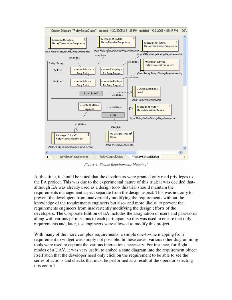
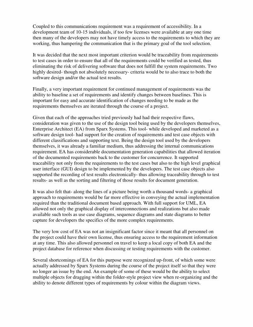
Figure 4: Simple Requirements Mapping i
At this time, it should be noted that the developers were granted only read privileges to
the EA project. This was due to the experimental nature of this trial; it was decided that-
although EA was already used as a design tool- this trial should maintain the
requirements management aspect separate from the design aspect. This was not only to
prevent the developers from inadvertently modifying the requirements without the
knowledge of the requirements engineers but also- and more likely- to prevent the
requirements engineers from inadvertently modifying the design efforts of the
developers. The Corporate Edition of EA includes the assignation of users and passwords
along with various permissions to each participant so this was used to ensure that only
requirements and, later, test engineers were allowed to modify this project.
With many of the more complex requirements, a simple one-to-one mapping from
requirement to widget was simply not possible. In these cases, various other diagramming
tools were used to capture the various interactions necessary. For instance, for flight
modes of a UAV, it was very useful to embed a state diagram into the requirement object
itself such that the developer need only click on the requirement to be able to see the
series of actions and checks that must be performed as a result of the operator selecting
this control.

Figure 5: EA Activity Diagram i
For even more complicated interactions, sequence diagrams were used to describe the
interactions between requirements, the user and external actors such as the vehicle, the
datalink radios or the landing system.

Figure 6: EA Sequence Diagram i
Often these diagrams described various relationships between requirements so these
would be reflected by using links between these requirements describing a variety of
relationships- such as Uses, Associate, Derives, etc. These links could be displayed on
the diagram itself (when both requirements were present within the same diagram) or
within a relationship view window so that, if one of those requirements changed, it was
easy for the requirements engineer to determine which other requirements, diagrams and
widget mock-ups to check to determine the impact of the change.
Not unexpectedly, these more complicated requirements mappings required more
lengthy, more detailed and more iterative requirements reviews. However, when
compared directly to previous projects in which similar requirements had had to be
implemented, this was far more manageable and resulted in far more accurate
implementations with far less re-work.
The problem of requirements updates and changes did, as expected, rear its ugly head on
several occasions. The inability of EA to be baselined at any point denied us the ability to
easily identify deltas. This was of particular frustration to the developers when it was a
complex implementation that they had already completed and thus were no longer
immediately familiar with it. Requirements revisions would be delivered by the customer,
the requirements mappings updated by the requirements engineer but the developer could
not tell from the EA diagram what had changed. Towards the end of the project, Sparx
Systems had added an ability to EA to allow colouring of the requirements object side bar
as a function of requirement type (though only of pre-defined requirement stereotypes,

not user-defined stereotypes). At this point, the requirements engineers used this feature
to identify the changes to the developers by manually changing the stereotype when
doing the updates so that the developer could tell by this colouring on the diagram what
needed to be changed.
Being manual, this did encounter some problems and disconnects but worked sufficiently
well to demonstrate that the use of a VBA app to compare the present EA Access
database to a stored baseline and modify the requirements stereotypes accordingly would
be both possible and usable.
With the requirements mapped, the requirements engineers would now don their test
engineering hats and proceed with test development. In this regard, EA supplies two
distinct means of developing tests: embedded test within each requirements object; and
separate test case objects. Both of these methods were examined for suitability with the
decision eventually falling to the use of separate test case objects. The advantage of using
this approach over the embedded tests was that it allowed test cases to test more than one
requirement simply by creating an association link between the test case and all the tested
requirements and the test object itself allowed the definition of test “titles” that
effectively defined a test plan, thus allowing more junior test engineers to develop the
actual tests, following this “plan”. It also allowed the requirement-test relationship to be
more easily examined and navigated through use of either the diagram view (by adding a
test case to the diagram), the relationship window or through the relationship matrix
capability that allows relationships to be displayed and printed in a large matrix format
between any sets of objects. This last was originally thought to be quite useful- especially
for delivery to the customer- in order to prove that each requirement had an associated
test. However, as the project took on realistic proportions, it was found that the matrix
became so large that its utility was severely hampered and use of the relationship window
became a far easier and more reliable means of ensuring that all requirements were
tested.

Figure 7: EA Test Cases i
The execution of test within EA was found to be far superior to the use of paper test
documents. The project view allows the methodical, linear execution that is necessary to
ensure that all tests are performed and none are missed. The use of electronic testing not
only allowed the lead test engineer to generate a testing status at any point but also
eliminated the necessity of each tester having to review their individual tests to ensure
that all comments and results are legible for the customer. Furthermore, especially in the
initial stages of a development project, it is not uncommon to discover during the
execution of a test that the test itself has some flaw and therefore requires a “red line” to
correct it. These “red lines” must be performed only by authorized personnel who can
confirm that the test itself is in error and not just failing but, once it is determined that the
test must be changed, these red lines could now be done in real time rather than requiring
to be re-visited after the testing evolution. This is a considerable and important savings,
especially in the instances where a testing evolution results in a correction that requires
the tests to be started over again. Previously, such a situation presented a risk of the “red
lines” being missed due to lack of time for updates so that the second set of tests could
use incorrect tests; however, the ability to perform these red lines in real time ensured
that the tests were always up-to-date regardless of how fast the turn-around time between
test events.
It was important to determine a means by which the test engineer could clearly identify
the complete software configuration being tested during each test event. This was
accomplished by writing a script that queried the version information from every file in
the software package and wrote this to a file. This file, in turn, was linked into the test
case objects within EA in the same manner that the requirements documents were linked
into the requirements objects, thus allowing full traceability from the test case to the
exact software configuration being tested.
EA allows the generation of full test reports in rich text format that can easily be opened
using Word and modified as to format, layout, title pages, etc. for delivery to the
customer. As well, there is an ability to generate test “reports” that allow filtering such as
by date, type, status, etc. The last is especially useful as the lead test engineer can filter
on all failed tests and examine them for their impact on the over-all testing effort (i.e. in
large system-level tests, the failure of some non-critical tests may not mean the failure of
a test event; the failures may simply be tracked for resolution in a later release without
interrupting the present effort). Unfortunately, these test reports- unlike the test
documentation- can only be printed and cannot be saved as a file itself.
It should be noted that while EA supports several different levels and types of testing-
unit, scenario, acceptance, etc.- only the acceptance testing was used in this effort. Unit
testing could potentially be useful to the developer- especially if they linked an associated
test file and/ or test result file into the test object- but of more interest to the test engineer
would be the integration or system test types which could be used to capture the fully
comprehensive verification testing performed on new features when they are first
introduced. These tests are highly rigorous and designed to test absolutely every aspect of
the new feature but often, due to the cost of running such rigorous and lengthy tests,
cannot reasonably be run in their entirety every time the software is released. Using the
system or integration test type to capture this level of testing would allow an easy
examination of the entire test history of every feature in the software.
One significant draw back in the EA testing capabilities was the inability to “reset” the
tests between test events. This resulted in the test cases- after the initial test event-
already having the Pass or Fail status assigned and this sometimes made it somewhat
difficult to determine if a given test case was already run or not, especially when the test
events were run right after each other so date was not a good indicator either. An ability
to have all the test cases “reset” to Not Run- potentially as a result of having the whole
EA project being baselined- would be of great benefit to the test engineer.
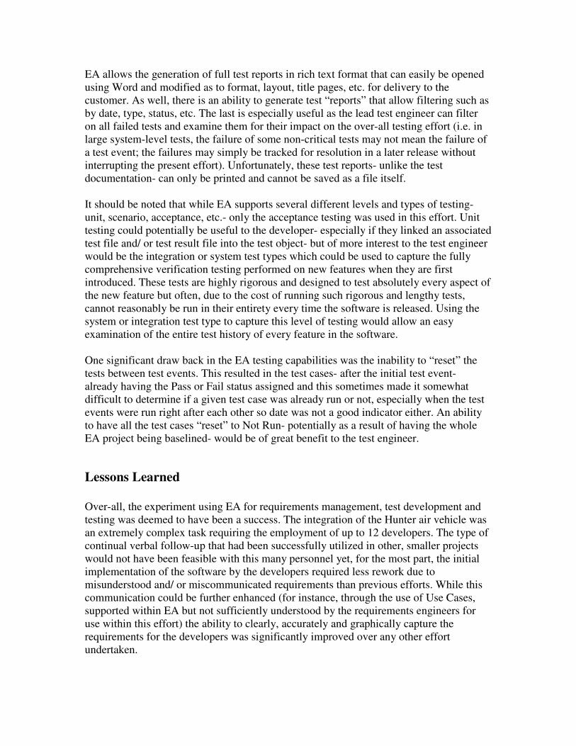
Lessons Learned
Over-all, the experiment using EA for requirements management, test development and
testing was deemed to have been a success. The integration of the Hunter air vehicle was
an extremely complex task requiring the employment of up to 12 developers. The type of
continual verbal follow-up that had been successfully utilized in other, smaller projects
would not have been feasible with this many personnel yet, for the most part, the initial
implementation of the software by the developers required less rework due to
misunderstood and/ or miscommunicated requirements than previous efforts. While this
communication could be further enhanced (for instance, through the use of Use Cases,
supported within EA but not sufficiently understood by the requirements engineers for
use within this effort) the ability to clearly, accurately and graphically capture the
requirements for the developers was significantly improved over any other effort
undertaken.

The availability and use of such graphical tools as state and sequence diagrams allowed
even very complex requirements and interactions to be captured in a manner that was
both clear and far less open to misinterpretation than the more traditional text-based
requirements tools.
The absence of an ability to baseline and identify deltas from that baseline is a critical
problem from the perspective of requirements management. While this effort was able to
surmount this problem through manual means, it is extremely prone to human error and,
thus, an automated means of accomplishing this must be developed before this tool could
be adopted for requirements management in anything more than an experimental manner.
At least for the development of a user interface, it is likely best to group the requirements
and test cases functionally with the graphical interface definition itself so as to best allow
the identification and documentation of the impact of changes and the determination of
regression testing.
The testing documentation is quite sufficient but it would be nice to be able to save the
test reports to a file for archiving or inclusion in status reports, etc.
Another thing that was noted while generating test cases was that- while EA allowed the
association of multiple test cases with multiple requirements- sometimes the test case in
question only tested part of the requirement. In these instances it would be very useful to
assign a “weighting” to the association being made to indicate that the requirement is not
yet fully tested. For instance, if a particular test case tests one of three possible states for
a specific requirement, assigning a weight of 1/3 would allow a reviewer to immediately
identify that that requirement is not yet fully tested and requires another test case to be
developed to test the other 2 states. This could be true of relationships in general- for
instance, perhaps the Realization relationship between a widget and a requirement should
also be capable of indicating only a partial implementation- but is most particularly true
of the test cases.
From the perspective of the CMMI effort, the approached used within EA was seen as
highly desirable- so long as the ability to baseline and determine deltas from a baseline
was addressed. The traceability within EA offers far more capability than traditional
requirements tools, specifically in that the requirements can not only trace to test and
even test cases, but even to the high level design itself. Once out of the experimental
stage, it could be expected that the EA project would encompass not only the
requirements, graphical design and test cases but would also include the low level design
and potentially even initial code generation once the development efforts were included
within the same project- EA is, after all, primarily a software design tool. However, it
should be noted that the inclusion of developers and requirements/ test engineers within
the same project would be wise to include a folder-level and/ or object type permissions
capability that is not presently available even within the Corporate Edition. Right now, a
user may be given read-only permission to all folders or be allowed to write to all
diagrams but cannot be allowed write permissions to only some diagrams and some
folders. The ability to divide access based on areas of responsibility would be highly

desirable and perhaps even necessary for a truly integrated EA approach to requirements
management, software design and test engineering.
Recommendations
Based on this experience with using EA for requirements management and test
development/ testing, a set of recommendations can be generated as a path forward for
the integration and use of this tool into project development.
1. Without a doubt, the single most important enhancement necessary to justify the
use of EA for requirements management is the ability to baseline the project, to
determine a delta from that baseline and to make the changes readily apparent to
anyone examining the project
2. In hindsight, it is obvious that the use of Use Cases- which are already supported
by EA- would have been very useful to even further improve communications
between the requirements engineers and the developers. Their absence in this
effort was not due to any technical limitation within EA but rather to the lack of
familiarity with Use Cases on the part of the requirements engineers. With
subsequent training in their development and utility, it is felt that future efforts
using EA should include the use of Use Cases to specifically explain the
interactions with each interface, including exception cases.
3. In parallel with the Hunter effort and as part of the over-all CMMI effort, a formal
requirements review process was implemented for requirements documents. This
review process should be modified to allow for the review of requirements within
the EA format rather than assume the inherently linear nature of a paper
document.
4. An ability to reset the status of all test cases should be developed- potentially as
part of baselining- to make it easier for test engineers to ensure that no tests are
inadvertently missed
5. The security controls within the Corporate Edition of EA should be enhanced to
allow diagram or folder-specific permissions for each user so as to allow the use
of a single EA project by requirements engineers, software developers and test
engineers for an integrated approach but without the risk of inadvertent alterations
by personnel outside their area of expertise
6. The ability to assign a “weight” to relationships, especially for test cases, would
be of great use in ensuring that all requirements were fully tested, especially if a
means of automatically flagging requirements/ objects with adjoining
relationships summing to less than 1.0
Conclusion
In conclusion, it can be stated that the use of enterprise Architect from Sparx Systems as
a requirements management, test development and testing tool was highly successful
during the integration of the Hunter air vehicle into the VCS ground control station.
Despite this being a non-standard use of this tool and a non-standard approach to the
mapping and management of requirements, it is felt that the graphical nature of this tool
not only eased the requirements management and communication process but also
enhanced the ability of senior requirements engineers to train more junior engineers on
the relationships between requirements, design and testing and thereby better delegate
tasks. With the advent of graphical interfaces for all manners of management and
communication tasks, the traditional approach to and the traditional tools of requirements
management seem particularly trapped within an old paradigm that EA is very effective
at breaking.
Although there are still some significant short falls within EA for this task, the
architecture of EA itself allows solutions to these problems to be developed and
implemented and, with these solutions, will make Enterprise Architect a powerful new
requirements tool that delivers all that you require….
i The requirements shown within this paper are representative only and do not reflect the protocol,
capabilities or implementation of the Hunter system. These diagrams have been specifically constructed for
this paper to demonstrate the points being made for the use of EA in a requirements management role only.