ALL PURPOSE, HIGH CAPACITY LOW OR HIGH TEMPERATURE BURNER
21
Mason, OH | USA +1-513-282-0810 starcombustion.com SYSTEMS LLC SYSTEMS LLC STARCOMBUSTION STAR|Bx ALL PURPOSE, HIGH CAPACITY LOW OR HIGH TEMPERATURE BURNER Flexible, all purpose design for low or high temperature applicaons Low NOx and CO emissions Excellent flame stability over a very wide range of air/fuel raos from fuel rich to high excess air Burner can operate using virtually any commercially available liquid or gas- eous fuel including low btu waste fuels and heavy fuel oil Mounng designed for an excellent seal in a wide variety of combuson chamber pressures
Transcript of ALL PURPOSE, HIGH CAPACITY LOW OR HIGH TEMPERATURE BURNER

Mason, OH | USA
+1-513-282-0810
starcombustion.com
SYSTEMS LLC SYSTEMS LLC
STARCOMBUSTION
STAR|Bx
ALL PURPOSE, HIGH CAPACITY LOW OR HIGH
TEMPERATURE BURNER
Flexible, all purpose design for low or high temperature applications
Low NOx and CO emissions
Excellent flame stability over a very wide range of air/fuel ratios from fuel
rich to high excess air
Burner can operate using virtually any commercially available liquid or gas-
eous fuel including low btu waste fuels and heavy fuel oil
Mounting designed for an excellent seal in a wide variety of combustion
chamber pressures

Features
The Star|Bx burner is an extremely flexible, all purpose
burner designed for both low and high temperature ap-
plications. The burner’s versatility makes it suitable for
everything from a 200°F air heating application to a
2800°F furnace application.
• Sizes range from 3,000,000 btu/hr to 150,000,000
btu/hr with higher capacities available upon request
• The flame is very stable over a wide range of air/
fuel ratios from excess air to fuel rich
• 15:1 turndown from maximum to minimum capacity
when running on gas
• Burns any clean fuel gas including natural gas, pro-
pane gas, butane gas, propane/air mix, and many
low btu waste fuels
• DF version adds liquid fuel capability to burn virtu-
ally any liquid fuel oil from #2 to #6/heavy fuel oil
heated to <100SSU viscosity
• Up to 8:1 turndown from maximum to minimum ca-
pacity when running on liquid fuels
• Refractory burner tile available for high temperature
applications
• Stainless steel burner tile available for low temper-
ature applications
• Burner can be ignited via direct spark ignition for
sizes B10x-xG and smaller
• Pilot ignition available on all burner sizes
• Flame sensing via UV scanner or flame ionization
rod
Mason, OH | USA
+1-513-282-0810
starcombustion.com SYSTEMS LLC
STARCOMBUSTION SYSTEMS LLC
Typical Applications
• Direct fired low or high temperature air heaters
• Direct fired high temperature furnaces
• Thermal oxidizers
• Rotary dryers
• Rotary kilns
• Fluid bed dryers
• Spray dryers
• Grain dryer
• All purpose design allows for use in virtually any
low or high temperature application
STAR|Bx ALL PURPOSE HIGH CAPACITY BURNER
Technical Guide Page 2

Model Bx Burner Size 04 06 08 10 12 14 Maximum Capacity (million btu/hr HHV) 3.0 6.0 12.0 20.0 30.0 40.0
Minimum Capacity (million btu/hr HHV) 0.2 0.4 0.8 1.35 2.0 2.67
Combustion Air Differential Pressure ("wc) 28.0 28.0 28.0 28.0 28.0 28.0
Combustion Air Flow (scfh, 15% Excess Air) 32,373 64,799 129,598 215,997 323,996 431,994
Combustion Air Flow (scfm, 15% Excess Air) 540 1,080 2,160 3,600 5,400 7,200
Natural Gas Differential Pressure ("wc) 8.0 8.0 8.0 8.0 8.0 8.0
Natural Gas Flow (scfh, 1002 btu/ft3, 0.6 sg) 2,994 5,988 11,976 19,960 29,940 39,920
Flame Length (ft) 6.0 8.0 10.0 12.0 15.0 16.0
Flame Diameter (ft) 1.5 2.0 3.0 4.0 4.0 4.5
Model Bx Burner Size 16 18 20 22 24 26 Maximum Capacity (million btu/hr HHV) 55.0 70.0 90.0 110.0 125.0 150.0
Minimum Capacity (million btu/hr HHV) 3.67 4.67 6.0 7.3 8.3 10.0
Combustion Air Differential Pressure ("wc) 28.0 28.0 28.0 28.0 28.0 28.0
Combustion Air Flow (scfh, 15% Excess Air) 593,992 755,990 971,987 1,187,984 1,349,993 1,619,989
Combustion Air Flow (scfm, 15% Excess Air) 9,900 12,600 16,200 19,800 22,500 27,000
Natural Gas Differential Pressure ("wc) 8.0 8.0 8.0 8.0 8.0 8.0
Natural Gas Flow (scfh, 1002 btu/ft3, 0.6 sg) 54,890 69,860 89,820 109,780 124,751 149,701
Flame Length, approx (ft) 17.0 17.0 19.0 20.0 25.0 28.0
Flame Diameter, approx (ft) 5.0 5.0 5.0 5.0 5.0 6.0
Notes:
The above calculations are determined using the following data:
1) Flame lengths are approximate and are measured from the end of the combustion sleeve firing with 15% excess air on
natural gas, consult Star Combustion for flame lengths using other fuels
2) Natural gas (Birmingham, AL) with HHV of 1002 btu/ft3, 0.6 specific gravity, and 9.41:1 stoichiometric air fuel ratio
3) Air and gas flows are based on operating conditions at standard temperature and pressures: 68°F ambient air at sea
level
4) To achieve full turndown of the burner, it should be set to run with 30% excess air at minimum capacity
5) Combustion differential air pressure shown is for the combustion air flow listed using 15% excess air
STARCOMBUSTION SYSTEMS LLC
Mason, OH | USA
+1-513-282-0810
starcombustion.com
STAR|Bx—SPECIFICATIONS
STAR|Bx ALL PURPOSE HIGH CAPACITY BURNER
Technical Guide Page 3

TABLE I - Burner Size
Abbreviation Definition
04 3,000,000 btu/hr HHV
06 6,000,000 btu/hr HHV
08 12,000,000 btu/hr HHV
10 20,000,000 btu/hr HHV
12 30,000,000 btu/hr HHV
14 40,000,000 btu/hr HHV
16 55,000,000 btu/hr HHV
18 70,000,000 btu/hr HHV
20 90,000,000 btu/hr HHV
22 110,000,000 btu/hr HHV
24 125,000,000 btu/hr HHV
26 150,000,000 btu/hr HHV
TABLE II - Air Nozzle
Abbreviation Definition
S Stainless steel, applications <1800°F
R Refractory, applications <2950°F
TABLE IV - Tile or Discharge Sleeve
Abbreviation Definition
S Stainless steel, applications <1800°F
R Refractory, applications <2950°F
X Customer supplied discharge sleeve/tile
TABLE V - Pilot Configuration
Abbreviation Definition
D Direct spark ignition, sizes B10 and smaller
P Star|Bx pilot assembly, all sizes
TABLE III - Fuel
Abbreviation Definition
G 100% gaseous fuel
DF Dual fuel - gas and oil
TABLE VI - Flame Sensing
Abbreviation Definition
FR Flame ionization rod, stainless air nozzle only
UV UV scanner, customer supplied
TABLE VII - Air Inlet Position
Abbreviation Definition
UB 12:00 position, as viewed from back of burner
AUR 1:30 position, as viewed from back of burner
HR 3:00 position, as viewed from back of burner
ADR 4:30 position, as viewed from back of burner
DB 6:00 position, as viewed from back of burner
ADL 7:30 position, as viewed from back of burner
HL 9:00 position, as viewed from back of burner
AUL 10:30 position, as viewed from back of burner
TABLE VIII - Gas Inlet Position
Abbreviation Definition
UB 12:00 position, as viewed from back of burner
AUR 1:30 position, as viewed from back of burner
HR 3:00 position, as viewed from back of burner
ADR 4:30 position, as viewed from back of burner
DB 6:00 position, as viewed from back of burner
ADL 7:30 position, as viewed from back of burner
HL 9:00 position, as viewed from back of burner
AUL 10:30 position, as viewed from back of burner
STARCOMBUSTION SYSTEMS LLC
Mason, OH | USA
+1-513-282-0810
starcombustion.com
STAR|B( I ) ( II ) ( III ) - ( IV ) ( V ) ( VI ) - ( VII ) ( VIII ) ( VIIII )
STAR|Bx—MODEL NUMBER
STAR|Bx ALL PURPOSE HIGH CAPACITY BURNER
Technical Guide Page 4
TABLE VIIII - Mounting Ring
Abbreviation Definition
M Include burner wall mounting ring with gaskets
X Customer supplied mounting ring
STARCOMBUSTION SYSTEMS LLC
Mason, OH | USA
+1-513-282-0810
starcombustion.com
STAR|Bx ALL PURPOSE HIGH CAPACITY BURNER
Technical Guide Page 5
STAR|Bx—DIMENSIONS REFRACTORY TILE
Size A B C D E # F G H I J Gas Inlet
Size
Air Inlet
Size
04 14.000 11.500 21.000 18.750 1.125 12 7.125 15.250 4.750 8.250 20.500 2” 4”
06 16.000 11.500 23.500 21.250 1.125 16 12.500 22.063 7.063 12.375 29.250 3” 6”
08 16.000 11.500 23.500 21.250 1.125 16 12.500 23.063 7.063 12.375 30.250 3” 8”
10 22.000 11.500 29.500 27.250 1.375 20 15.000 29.963 7.125 13.500 33.250 3” 10”
12 24.000 11.500 32.000 29.500 1.375 20 17.000 30.563 8.500 14.500 39.500 4” 12”
14 26.000 11.500 34.250 31.750 1.375 24 18.000 33.563 8.750 15.500 41.250 6” 14”
16 28.000 11.500 36.500 34.000 1.375 24 17.750 36.188 8.875 15.625 45.250 6” 16”
18 30.000 17.500 38.750 36.000 1.375 28 20.000 39.750 9.875 17.500 53.625 6” 18”
20 34.000 17.500 43.750 40.500 1.625 32 21.750 42.125 11.250 20.000 53.500 6” 20”
22 38.000 17.500 48.750 42.250 1.625 32 23.500 45.500 11.250 22.000 54.750 6” 22”
24 40.000 23.500 50.750 47.250 1.625 36 23.500 46.625 11.250 23.000 58.500 6” 24”
26 44.000 23.500 55.250 51.750 1.625 40 25.500 49.75 11.250 25.000 59.000 6” 26”
Dimension listed are for general use should not be used for installation drawings. Certified drawings should be obtained from Star Combustion Systems LLC to prevent any
confusion or inaccuracies. Dimensions in the catalog are subject to change without notice.
Air inlet flanges conform to ANSI 125# FF dimensions
Gas inlet flanges are standard ANSI 150# RF flanges
Burner and tile mounting flanges conform to ANSI 125# FF dimensions

STARCOMBUSTION SYSTEMS LLC
Mason, OH | USA
+1-513-282-0810
starcombustion.com
STAR|Bx ALL PURPOSE HIGH CAPACITY BURNER
Technical Guide Page 6
STAR|Bx—DIMENSIONS STAINLESS SLEEVE
Size A B C D E # 04 10.563 11.500 16.000 14.250 1.000 12
06 12.563 11.500 19.000 17.000 1.000 12
08 12.563 11.500 19.000 17.000 1.000 12
10 18.563 11.500 25.000 22.750 1.250 16
12 20.563 11.500 27.500 25.000 1.250 20
14 22.563 11.500 29.500 27.250 1.375 20
16 24.563 11.500 23.000 29.500 1.375 20
18 26.563 17.500 34.250 31.750 1.375 24
20 30.563 17.500 38.750 36.000 1.375 28
22 34.563 17.500 43.750 40.500 1.625 32
24 36.563 23.500 46.000 42.750 1.625 32
26 40.563 23.500 50.750 17.250 1.625 36
Dimension listed are for general use should not be used for installation drawings. Certified drawings should be obtained from Star Combustion Systems LLC to prevent any
confusion or inaccuracies. Dimensions in the catalog are subject to change without notice.
Burner and tile mounting flanges conform to ANSI 125# FF dimensions
STARCOMBUSTION SYSTEMS LLC
Mason, OH | USA
+1-513-282-0810
starcombustion.com
STAR|Bx ALL PURPOSE HIGH CAPACITY BURNER
Technical Guide Page 7
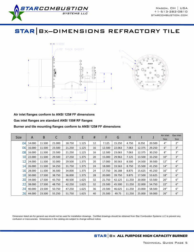
STAR|Bx—DIMENSIONS STAR|Bx—DIMENSIONS
Size AA BB CC # DD EE FF GG # 04 9.000 7.500 0.750 8 4.500 6.000 4.750 0.750 4
06 11.000 9.500 0.875 8 6.625 7.500 6.000 0.750 4
08 13.500 11.750 0.875 8 8.625 7.500 6.000 0.750 4
10 16.000 14.250 1.000 12 10.750 7.500 6.000 0.750 4
12 19.000 17.000 1.000 12 12.750 9.000 7.500 0.750 8
14 21.000 18.50 1.125 12 14.000 11.000 9.500 0.875 8
16 23.500 21.250 1.125 16 16.000 11.000 9.500 0.875 8
18 25.000 22.750 1.250 16 18.000 11.000 9.500 0.875 8
20 27.500 25.000 1.250 20 20.000 11.000 9.500 0.875 8
22 29.500 27.250 1.375 20 22.000 11.000 9.500 0.875 8
24 32.000 29.500 1.375 20 24.000 11.000 9.500 0.875 8
26 34.250 31.750 1.375 24 26.000 11.000 9.500 0.875 8
AIR AND GAS INLET FLANGE DIMENSIONS
Air inlet flanges conform to ANSI 125# FF dimensions
Gas inlet flanges are standard ANSI 150# RF flanges
Dimension listed are for general use should not be used for installation drawings. Certified drawings should be obtained from Star Combustion Systems LLC to prevent any
confusion or inaccuracies. Dimensions in the catalog are subject to change without notice.

STARCOMBUSTION SYSTEMS LLC
Mason, OH | USA
+1-513-282-0810
starcombustion.com
STAR|Bx ALL PURPOSE HIGH CAPACITY BURNER
Technical Guide Page 8
STAR|Bx—DIMENSIONS STAR|Bx—DIMENSIONS
Size A B C D E #
04 14.000 11.500 21.000 18.750 1.125 12
06 16.000 11.500 23.500 21.250 1.125 16
08 16.000 11.500 23.500 21.250 1.125 16
10 22.000 11.500 29.500 27.250 1.375 20
12 24.000 11.500 32.000 29.500 1.375 20
14 26.000 11.500 34.250 31.750 1.375 24
16 28.000 11.500 36.500 34.000 1.375 24
18 30.000 17.500 38.750 36.000 1.375 28
20 34.000 17.500 43.750 40.500 1.625 32
22 38.000 17.500 48.750 42.250 1.625 32
24 40.000 23.500 50.750 47.250 1.625 36
26 44.000 23.500 55.250 51.750 1.625 40
Size A B C D E #
04 10.563 11.500 16.000 14.250 1.000 12
06 12.563 11.500 19.000 17.000 1.000 12
08 12.563 11.500 19.000 17.000 1.000 12
10 18.563 11.500 25.000 22.750 1.250 16
12 20.563 11.500 27.500 25.000 1.250 20
14 22.563 11.500 29.500 27.250 1.375 20
16 24.563 11.500 23.000 29.500 1.375 20
18 26.563 17.500 34.250 31.750 1.375 24
20 30.563 17.500 38.750 36.000 1.375 28
22 34.563 17.500 43.750 40.500 1.625 32
24 36.563 23.500 46.000 42.750 1.625 32
26 40.563 23.500 50.750 17.250 1.625 36
STAINLESS STEEL SLEEVE DIMENSIONS
REFRACTORY TILE DIMENSIONS
Burner and tile mounting flanges conform to ANSI 125# FF dimensions
Dimension listed are for general use should not be used for installation drawings. Certified drawings should be obtained from Star Combustion Systems LLC to prevent any
confusion or inaccuracies. Dimensions in the catalog are subject to change without notice.

STARCOMBUSTION SYSTEMS LLC
Mason, OH | USA
+1-513-282-0810
starcombustion.com
STAR|Bx—PILOT DATA
STAR|Bx ALL PURPOSE HIGH CAPACITY BURNER
Technical Guide Page 9
Please read all installation and commissioning instructions before proceeding with installation.
Supply pilot combustion air at 10”-60”wc. The Star|Bx Pilot burner is a premix pilot and requires combustion air for prop-
er operation.
The Star|Bx Pilot capacity is approximately 100,000 btu/hr with a combustion air inlet pressure of 28”wc. The capacity
will be higher with more combustion air pressure, and lower with less.
Supply pilot gas pressure to the pilot ratio regulator inlet at 14”wc –28”wc. Gas pressure should not exceed 28”wc or ratio
regulator damage may result.
With constant combustion air to the mixer inlet, use the gas adjusting screw to adjust the pilot flame. It is sometimes
easier to adjust the pilot with the pilot removed from the burner, firing into open air.
STARCOMBUSTION SYSTEMS LLC
Mason, OH | USA
+1-513-282-0810
starcombustion.com
STAR|Bx ALL PURPOSE HIGH CAPACITY BURNER
Technical Guide Page 10
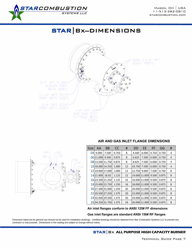
Please read all installation and commissioning instructions
before proceeding with installation.
*** IMPORTANT ***
Installation and commissioning should
only be done by properly trained and
qualified personnel. Failure to do so can
result in significant property damage, and
injury or death to personnel. Follow all
applicable piping and gas safety codes
when installing and commissioning this
system.
The Star|Bx burner is an integral part of an industrial heat-
ing process. Combustion chamber, system fans, fuel train,
burner management, temperature controls, high tempera-
ture limit, and corresponding ductwork must be supplied to
compete the heating system for the equipment operation.
The Star|Bx may require external support. Use a support
positioned near the back of the burner to the floor in in-
stances where the heater wall is not robust enough to sup-
port the burner.
A wall gasket should be used between the burner tile or
discharge sleeve and the heater wall. This is especially
important for instances where there is a back pressure in
the combustion chamber.
A flat surface between the burner tile flange and the heater
wall is necessary to seal the burner in on high back pres-
sure combustion chambers. A burner mounting ring with
studs can be provided by Star Combustion Systems. This
mounting ring comes with burner mounting studs pre-
installed and is seal welded on to the combustion chamber
wall.
The Star|Bx burner can be mounted and fired in any direc-
tion. If up firing the burner, care should be taken so that
debris cannot fall into the burner and cause blockage of the
air or gas nozzle.
Contact Star Combustion Systems LLC at +1-513-282-
0810 or [email protected] for questions or fur-
ther information.
STAR|Bx—INSTALLATION

STARCOMBUSTION SYSTEMS LLC
Mason, OH | USA
+1-513-282-0810
starcombustion.com
STAR|Bx—INSTALLATION
STAR|Bx ALL PURPOSE HIGH CAPACITY BURNER
Technical Guide Page 11
REFRACTORY TILE
STAINLESS STEEL DISCHARGE SLEEVE
STARCOMBUSTION SYSTEMS LLC
Mason, OH | USA
+1-513-282-0810
starcombustion.com
STAR|Bx—COMMISSIONING
STAR|Bx ALL PURPOSE HIGH CAPACITY BURNER
Technical Guide Page 12
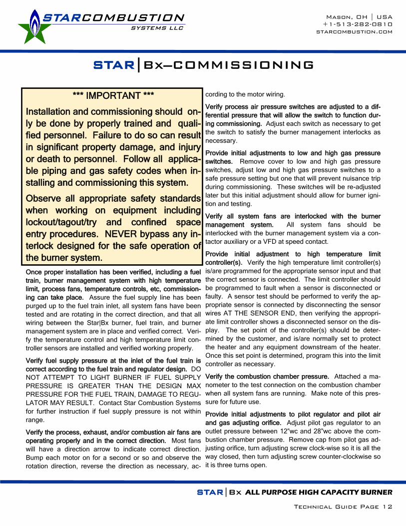
*** IMPORTANT ***
Installation and commissioning should on-
ly be done by properly trained and quali-
fied personnel. Failure to do so can result
in significant property damage, and injury
or death to personnel. Follow all applica-
ble piping and gas safety codes when in-
stalling and commissioning this system.
Observe all appropriate safety standards
when working on equipment including
lockout/tagout/try and confined space
entry procedures. NEVER bypass any in-
terlock designed for the safe operation of
the burner system.
Once proper installation has been verified, including a fuel
train, burner management system with high temperature
limit, process fans, temperature controls, etc, commission-
ing can take place. Assure the fuel supply line has been
purged up to the fuel train inlet, all system fans have been
tested and are rotating in the correct direction, and that all
wiring between the Star|Bx burner, fuel train, and burner
management system are in place and verified correct. Veri-
fy the temperature control and high temperature limit con-
troller sensors are installed and verified working properly.
Verify fuel supply pressure at the inlet of the fuel train is
correct according to the fuel train and regulator design. DO
NOT ATTEMPT TO LIGHT BURNER IF FUEL SUPPLY
PRESSURE IS GREATER THAN THE DESIGN MAX
PRESSURE FOR THE FUEL TRAIN, DAMAGE TO REGU-
LATOR MAY RESULT. Contact Star Combustion Systems
for further instruction if fuel supply pressure is not within
range.
Verify the process, exhaust, and/or combustion air fans are
operating properly and in the correct direction. Most fans
will have a direction arrow to indicate correct direction.
Bump each motor on for a second or so and observe the
rotation direction, reverse the direction as necessary, ac-
cording to the motor wiring.
Verify process air pressure switches are adjusted to a dif-
ferential pressure that will allow the switch to function dur-
ing commissioning. Adjust each switch as necessary to get
the switch to satisfy the burner management interlocks as
necessary.
Provide initial adjustments to low and high gas pressure
switches. Remove cover to low and high gas pressure
switches, adjust low and high gas pressure switches to a
safe pressure setting but one that will prevent nuisance trip
during commissioning. These switches will be re-adjusted
later but this initial adjustment should allow for burner igni-
tion and testing.
Verify all system fans are interlocked with the burner
management system. All system fans should be
interlocked with the burner management system via a con-
tactor auxiliary or a VFD at speed contact.
Provide initial adjustment to high temperature limit
controller(s). Verify the high temperature limit controller(s)
is/are programmed for the appropriate sensor input and that
the correct sensor is connected. The limit controller should
be programmed to fault when a sensor is disconnected or
faulty. A sensor test should be performed to verify the ap-
propriate sensor is connected by disconnecting the sensor
wires AT THE SENSOR END, then verifying the appropri-
ate limit controller shows a disconnected sensor on the dis-
play. The set point of the controller(s) should be deter-
mined by the customer, and is/are normally set to protect
the heater and any equipment downstream of the heater.
Once this set point is determined, program this into the limit
controller as necessary.
Verify the combustion chamber pressure. Attached a ma-
nometer to the test connection on the combustion chamber
when all system fans are running. Make note of this pres-
sure for future use.
Provide initial adjustments to pilot regulator and pilot air
and gas adjusting orifice. Adjust pilot gas regulator to an
outlet pressure between 12”wc and 28”wc above the com-
bustion chamber pressure. Remove cap from pilot gas ad-
justing orifice, turn adjusting screw clock-wise so it is all the
way closed, then turn adjusting screw counter-clockwise so
it is three turns open.

STARCOMBUSTION SYSTEMS LLC
Mason, OH | USA
+1-513-282-0810
starcombustion.com
STAR|Bx—COMMISSIONING
STAR|Bx ALL PURPOSE HIGH CAPACITY BURNER
Technical Guide Page 13
Verify initial adjustments to main gas regulator. Adjust
main gas regulator to an outlet pressure between 12”wc
and 28”wc higher than the combustion chamber pressure.
Test main and blocking gas shut off valve proof of closure
switches. This test should be done with the burner off,
before attempting ignition for the first time. With all the
manual gas valves closed, remove the main gas shut off
valve actuator from the gas valve body and verify the
burner management systems indicates a fault. Repeat this
procedure for the blocking gas shut off valve. Contact Star
Combustion for this test procedure when using Maxon
brand shut off valves.
Test valve proving system, if used. Close downstream
manual gas valve and attempt valve proving test, verify it
indicates failure of the main gas shut off valve. Next, close
upstream manual gas valve and attempt valve proving test,
verify it indicates failure of the blocking gas shut off valve.
Set combustion air control valve at minimum position.
Using the air fuel ratio controller, set the main combustion
air control valve so the combustion air differential pressure,
measured between the combustion air test connection and
the combustion chamber, reads 0.3”wc at the minimum or
lightoff position. Refer to instructions for the air fuel ratio
controller being used for further information on how to set
this valve.
Set combustion air control valve at maximum position.
Using the air fuel ratio controller, set the main combustion
air control valve so the combustion air differential pressure,
measured between the combustion air test connection and
the combustion chamber, reads 28”wc at the maximum or
purge position. This should be done with all the system
fans running. Refer to instructions for the air fuel ratio con-
troller being used for further information on how to set this
valve.
Put the burner firing rate controller in manual and verify it is
at the minimum or lightoff firing rate position. Refer to in-
structions for the air fuel ratio controller being used for fur-
ther information on how to place the air/fuel ratio controller
or firing rate controller in manual mode.
Start the burner. If using a burner management control
panel provided by Star Combustion Systems LLC, refer to
the sequence of operation provided with that control panel
for directions on how to start the burner. If burner manage-
ment is not provided by Star Combustion Systems LLC,
refer to the manufacturer’s provided literature for instruction
on how to start the burner.
Once the burner management system has verified all sys-
tem interlocks, it will automatically go into a purge se-
quence. For applications that use the combustion air for
purge, the air fuel ratio controller will requested to drive the
combustion air control valve to maximum or purge position.
This position must be proven with a purge position switch
physically mounted to the air/fuel ratio controller air control
valve, or from the air/fuel ratio controller purge position
switch output. Some applications will alternatively use a
purge air pressure switch for this feedback instead of a po-
sition switch. For applications that do not use combustion
air for purging, the burner management system will normal-
ly keep the combustion air control valve at minimum or
lightoff position for purge.
The burner management system should be in the purge
sequence for enough time to change the air in the combus-
tion chamber at least 4 times prior to lightoff. Refer to the
system documentation for the setting of this purge time, if
adjustable in the burner management controls.
Once the purge is complete, the burner management sys-
tem will request that the air fuel ratio controller drive both
the combustion air control valve and the fuel control valve
to minimum or lightoff position. This position must be prov-
en with a lightoff position switch physically mounted to the
air/fuel ratio controller gas control valve, or from the air/fuel
ratio controller purge position switch output.
Once lightoff position is proven, the burner management
system will turn on the spark ignition transformer and also
the pilot shut off valves (or main shut off valves if the sys-
tem is set up for direct spark ignition.) A spark will not be
visible from the sight port of the burner.
Once spark is established, the pilot (or minimum main
flame in a direct spark system) should light within 2-3 sec-
onds. If the pilot/main does not light within the pilot flame
establishing period (normally 10 seconds), verify the
manual gas shut off valves are on, verify the pilot/main gas
pressure is adjusted to 12-28”wc above the combustion
chamber pressure, and that the pilot gas adjusting orifice is
3 turns open. Also check that the pilot solenoid valves are
wired correctly and are opening at the appropriate time.

STARCOMBUSTION SYSTEMS LLC
Mason, OH | USA
+1-513-282-0810
starcombustion.com
STAR|Bx—COMMISSIONING
STAR|Bx ALL PURPOSE HIGH CAPACITY BURNER
Technical Guide Page 14
Further, check for loose pilot gas connections, and obstruc-
tions in the pilot at the burner.
The pilot should be visible from the burner sight port and
should be a hard blue flame. If the flame is orange or
transparent, adjust the pilot gas adjusting orifice according-
ly.
Verify main flame. Once the pilot is established, the main
gas valves should open and allow main gas to flow to the
burner. IMPORTANT! Verify that the pilot flame is extin-
guished after the main flame establishing period, normally
10 seconds after the main gas valves are opened.
Once the burner management system has interrupted the
pilot, visually verify the main flame is lit all the way around
the base of the burner air nozzle and provides a good flame
signal. Refer to the instructions for the burner management
system for a definition of what a good flame signal should
be.
With the burner ignited, re-verify the main gas regulator
outlet pressure is between 12”wc and 28”wc and adjust
accordingly.
Test burner interlocks. Once the main flame is established,
all burner interlocks must be tested for proper operation
and set according to the applicable fuel gas code
instructions. IMPORTANT! If there is a burner interlock
failure during testing, the burner system should not be used
until the interlock is repaired and verified working correctly.
DO NOT ATTEMPT TO BYPASS A BURNER INTERLOCK
FOR ANY REASON.
With the burner on and at minimum fire, the interlocks
should shut off the burner and the appropriate alarm should
be displayed on the burner management controls. Manual
intervention should be necessary to re-start the burner after
an interlock failure.
Test the high temperature limit controller(s) by bringing
the set point below actual. The final set point of the
controller(s) should be determined by the customer,
and is/are normally set to protect the heater and any
process equipment downstream of the heater.
Test the low gas pressure switch by bringing the set
point below actual. The final setting of this switch
should be determined by local fuel gas codes, normally
50% below the lowest manifold pressure measured at
the switch (normally seen at high fire.)
Test the high gas pressure switch by bringing the set
point above actual. The final setting of this switch
should be determined by local fuel gas codes, normally
50% above the highest manifold pressure measured at
the switch (normally seen at low fire.)
Test the process air pressure switch by disconnecting
the upstream sensing port. The final setting of this
switch should be 0.4”wc.
Test the combustion air pressure switch by disconnect-
ing the upstream sending port. The final setting of this
switch should be 50% below the lowest air manifold
pressure measured at the switch (normally seen at high
fire.)
Test exhaust and other air pressure switches by
bringing the set point below actual or disconnecting the
sensing port(s). Final settings of these switches should
be determined by the local fuel gas codes, normally
50% below the lowest pressure measured at the
switch.
Test the flame sensor by shutting off the manual gas
valve in the main fuel downstream of the shut off valves
when the burner is ignited.
Test the low position switch by bringing the control
valve or actuator to a higher setting than the switch and
attempting to ignite the burner. IMPORTANT! Close
the pilot manual gas valve before attempting this test to
prevent un-intended ignition.
There may be more interlocks present, test those as
necessary according to the instructions for the burner
management system.
Set air and gas pressures at index positions. Once the
burner has been ignited and all interlocks tested and veri-
fied working correctly, verify the system can handle addi-
tional temperature and heat load. IMPORTANT! Verify
that the high temperature limit is protecting downstream
equipment from unintended heating during commissioning.
Some product load inside the process equipment may be
necessary to absorb the heat and allow proper high fire gas
adjustments.

STARCOMBUSTION SYSTEMS LLC
Mason, OH | USA
+1-513-282-0810
starcombustion.com
STAR|Bx—COMMISSIONING
STAR|Bx ALL PURPOSE HIGH CAPACITY BURNER
Technical Guide Page 15
Use a manometer to measure differential combustion air
and gas pressure between the combustion air pressure test
connection and the downstream heater pressure connec-
tions, as well as the gas pressure test connection and the
downstream heater pressure connection.
Use the charts provided in the following pages to set com-
bustion air and gas pressures according to each air fuel
ratio controller index position. Refer to instructions for the
air fuel ratio controller being used for further information on
how to make these adjustments. Once the differential pres-
sures have been set at all firing rates, re-attached the actu-
ator linkage, or place the air fuel ratio controller into auto-
matic mode and verify proper burner firing rate control. The
burner is now ready for operation.
Once the heater and system reach full operating tempera-
ture/capacity, re-verify all pressures and set points on the
burner interlocks. It is always wise to keep good records of
both burner settings and all interlock settings to refer back
to during troubleshooting.
For more information contact:
Star Combustion Systems LLC
PO Box 636
Mason, OH 45040
www.starcombustion.com
+1-513-282-0810

Star Combustion B04 Burner
Burner Firing Rate
Burner Capac-ity (btu/hr)
Gas Flow (scfh)
Gas Press Setting ("wc)
Desired Air Fuel Ratio
(X:1) Air Flow
(scfh) Air Flow
(scfm)
Air Press Setting ("wc)
0.0% 200,000 200 0.0 12.2 2,442 41 0.2
10.0% 480,000 479 0.2 11.3 5,409 90 0.8
20.0% 760,000 758 0.5 10.8 8,208 137 1.8
30.0% 1,040,000 1038 1.0 10.8 11,232 187 3.4
40.0% 1,320,000 1317 1.5 10.8 14,256 238 5.4
50.0% 1,600,000 1597 2.3 10.8 17,280 288 8.0
60.0% 1,880,000 1876 3.1 10.8 20,304 338 11.0
70.0% 2,160,000 2156 4.1 10.8 23,328 389 14.5
80.0% 2,440,000 2435 5.3 10.8 26,352 439 18.6
90.0% 2,720,000 2715 6.6 10.8 29,376 490 23.1
100.0% 3,000,000 2994 8.0 10.8 32,400 540 28.0
Star Combustion B06 Burner
Burner Firing Rate
Burner Capac-ity (btu/hr)
Gas Flow (scfh)
Gas Press Setting ("wc)
Desired Air Fuel Ratio
(X:1) Air Flow
(scfh) Air Flow
(scfm)
Air Press Setting ("wc)
0.0% 400,000 399 0.0 12.2 4,883 81 0.2
10.0% 960,000 958 0.2 11.3 10,819 180 0.8
20.0% 1,520,000 1517 0.5 10.8 16,416 274 1.8
30.0% 2,080,000 2076 1.0 10.8 22,464 374 3.4
40.0% 2,640,000 2635 1.5 10.8 28,512 475 5.4
50.0% 3,200,000 3194 2.3 10.8 34,560 576 8.0
60.0% 3,760,000 3752 3.1 10.8 40,608 677 11.0
70.0% 4,320,000 4311 4.1 10.8 46,656 778 14.5
80.0% 4,880,000 4870 5.3 10.8 52,704 878 18.5
90.0% 5,440,000 5429 6.6 10.8 58,751 979 23.0
100.0% 6,000,000 5988 8.0 10.8 64,799 1,080 28.0
STARCOMBUSTION SYSTEMS LLC
Mason, OH | USA
+1-513-282-0810
starcombustion.com
STAR|Bx—NATURAL GAS SETTINGS
STAR|Bx ALL PURPOSE HIGH CAPACITY BURNER
Technical Guide Page 16
The above calculations are determined using the following data:
1) Flame lengths are approximate and are measured from the end of the combustion sleeve firing with 15% excess air on
natural gas, consult Star Combustion for flame lengths using other fuels
2) Natural gas (Birmingham, AL) with HHV of 1002 btu/ft3, 0.6 specific gravity, and 9.41:1 stoichiometric air fuel ratio
3) Air and gas flows are based on operating conditions at standard temperature and pressures: 68°F ambient air at sea
level
4) To achieve full turndown of the burner, it should be set to run with 30% excess air at minimum capacity
5) Combustion differential air pressure shown is for the combustion air flow listed using 15% excess air
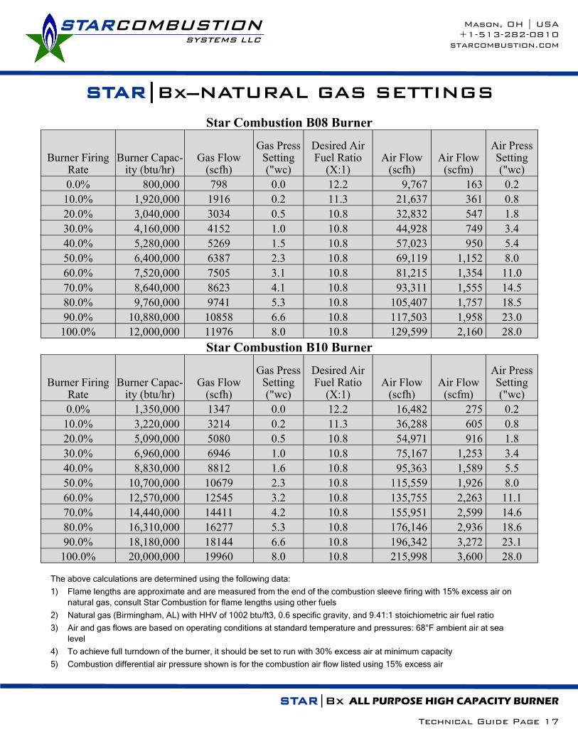
Star Combustion B08 Burner
Burner Firing Rate
Burner Capac-ity (btu/hr)
Gas Flow (scfh)
Gas Press Setting ("wc)
Desired Air Fuel Ratio
(X:1) Air Flow
(scfh) Air Flow
(scfm)
Air Press Setting ("wc)
0.0% 800,000 798 0.0 12.2 9,767 163 0.2
10.0% 1,920,000 1916 0.2 11.3 21,637 361 0.8
20.0% 3,040,000 3034 0.5 10.8 32,832 547 1.8
30.0% 4,160,000 4152 1.0 10.8 44,928 749 3.4
40.0% 5,280,000 5269 1.5 10.8 57,023 950 5.4
50.0% 6,400,000 6387 2.3 10.8 69,119 1,152 8.0
60.0% 7,520,000 7505 3.1 10.8 81,215 1,354 11.0
70.0% 8,640,000 8623 4.1 10.8 93,311 1,555 14.5
80.0% 9,760,000 9741 5.3 10.8 105,407 1,757 18.5
90.0% 10,880,000 10858 6.6 10.8 117,503 1,958 23.0
100.0% 12,000,000 11976 8.0 10.8 129,599 2,160 28.0
Star Combustion B10 Burner
Burner Firing Rate
Burner Capac-ity (btu/hr)
Gas Flow (scfh)
Gas Press Setting ("wc)
Desired Air Fuel Ratio
(X:1) Air Flow
(scfh) Air Flow
(scfm)
Air Press Setting ("wc)
0.0% 1,350,000 1347 0.0 12.2 16,482 275 0.2
10.0% 3,220,000 3214 0.2 11.3 36,288 605 0.8
20.0% 5,090,000 5080 0.5 10.8 54,971 916 1.8
30.0% 6,960,000 6946 1.0 10.8 75,167 1,253 3.4
40.0% 8,830,000 8812 1.6 10.8 95,363 1,589 5.5
50.0% 10,700,000 10679 2.3 10.8 115,559 1,926 8.0
60.0% 12,570,000 12545 3.2 10.8 135,755 2,263 11.1
70.0% 14,440,000 14411 4.2 10.8 155,951 2,599 14.6
80.0% 16,310,000 16277 5.3 10.8 176,146 2,936 18.6
90.0% 18,180,000 18144 6.6 10.8 196,342 3,272 23.1
100.0% 20,000,000 19960 8.0 10.8 215,998 3,600 28.0
STARCOMBUSTION SYSTEMS LLC
Mason, OH | USA
+1-513-282-0810
starcombustion.com
STAR|Bx—NATURAL GAS SETTINGS
STAR|Bx ALL PURPOSE HIGH CAPACITY BURNER
Technical Guide Page 17
The above calculations are determined using the following data:
1) Flame lengths are approximate and are measured from the end of the combustion sleeve firing with 15% excess air on
natural gas, consult Star Combustion for flame lengths using other fuels
2) Natural gas (Birmingham, AL) with HHV of 1002 btu/ft3, 0.6 specific gravity, and 9.41:1 stoichiometric air fuel ratio
3) Air and gas flows are based on operating conditions at standard temperature and pressures: 68°F ambient air at sea
level
4) To achieve full turndown of the burner, it should be set to run with 30% excess air at minimum capacity
5) Combustion differential air pressure shown is for the combustion air flow listed using 15% excess air

Star Combustion B12 Burner
Burner Firing Rate
Burner Capac-ity (btu/hr)
Gas Flow (scfh)
Gas Press Setting ("wc)
Desired Air Fuel Ratio
(X:1) Air Flow
(scfh) Air Flow
(scfm)
Air Press Setting ("wc)
0.0% 2,000,000 1996 0.0 12.2 24,417 407 0.2
10.0% 4,800,000 4790 0.2 11.3 54,093 902 0.8
20.0% 7,600,000 7585 0.5 10.8 82,079 1,368 1.8
30.0% 10,400,000 10379 1.0 10.8 112,319 1,872 3.4
40.0% 13,200,000 13174 1.5 10.8 142,559 2,376 5.4
50.0% 16,000,000 15968 2.3 10.8 172,798 2,880 8.0
60.0% 18,800,000 18762 3.1 10.8 203,038 3,384 11.0
70.0% 21,600,000 21557 4.1 10.8 233,278 3,888 14.5
80.0% 24,400,000 24351 5.3 10.8 263,518 4,392 18.5
90.0% 27,200,000 27146 6.6 10.8 293,757 4,896 23.0
100.0% 30,000,000 29940 8.0 10.8 323,997 5,400 28.0
Star Combustion B14 Burner
Burner Firing Rate
Burner Capac-ity (btu/hr)
Gas Flow (scfh)
Gas Press Setting ("wc)
Desired Air Fuel Ratio
(X:1) Air Flow
(scfh) Air Flow
(scfm)
Air Press Setting ("wc)
0.0% 2,670,000 2665 0.0 12.2 32,597 543 0.2
10.0% 6,410,000 6397 0.2 11.3 72,237 1,204 0.8
20.0% 10,150,000 10130 0.5 10.8 109,619 1,827 1.8
30.0% 13,890,000 13862 1.0 10.8 150,011 2,500 3.4
40.0% 17,630,000 17595 1.6 10.8 190,402 3,173 5.4
50.0% 21,370,000 21327 2.3 10.8 230,794 3,847 8.0
60.0% 25,110,000 25060 3.2 10.8 271,185 4,520 11.0
70.0% 28,850,000 28792 4.2 10.8 311,577 5,193 14.6
80.0% 32,590,000 32525 5.3 10.8 351,969 5,866 18.6
90.0% 36,330,000 36257 6.6 10.8 392,360 6,539 23.1
100.0% 40,000,000 39920 8.0 10.8 431,996 7,200 28.0
STARCOMBUSTION SYSTEMS LLC
Mason, OH | USA
+1-513-282-0810
starcombustion.com
STAR|Bx—NATURAL GAS SETTINGS
STAR|Bx ALL PURPOSE HIGH CAPACITY BURNER
Technical Guide Page 18
The above calculations are determined using the following data:
1) Flame lengths are approximate and are measured from the end of the combustion sleeve firing with 15% excess air on
natural gas, consult Star Combustion for flame lengths using other fuels
2) Natural gas (Birmingham, AL) with HHV of 1002 btu/ft3, 0.6 specific gravity, and 9.41:1 stoichiometric air fuel ratio
3) Air and gas flows are based on operating conditions at standard temperature and pressures: 68°F ambient air at sea
level
4) To achieve full turndown of the burner, it should be set to run with 30% excess air at minimum capacity
5) Combustion differential air pressure shown is for the combustion air flow listed using 15% excess air
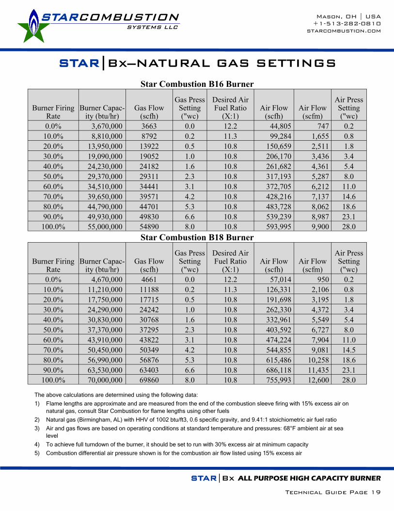
Star Combustion B16 Burner
Burner Firing Rate
Burner Capac-ity (btu/hr)
Gas Flow (scfh)
Gas Press Setting ("wc)
Desired Air Fuel Ratio
(X:1) Air Flow
(scfh) Air Flow
(scfm)
Air Press Setting ("wc)
0.0% 3,670,000 3663 0.0 12.2 44,805 747 0.2
10.0% 8,810,000 8792 0.2 11.3 99,284 1,655 0.8
20.0% 13,950,000 13922 0.5 10.8 150,659 2,511 1.8
30.0% 19,090,000 19052 1.0 10.8 206,170 3,436 3.4
40.0% 24,230,000 24182 1.6 10.8 261,682 4,361 5.4
50.0% 29,370,000 29311 2.3 10.8 317,193 5,287 8.0
60.0% 34,510,000 34441 3.1 10.8 372,705 6,212 11.0
70.0% 39,650,000 39571 4.2 10.8 428,216 7,137 14.6
80.0% 44,790,000 44701 5.3 10.8 483,728 8,062 18.6
90.0% 49,930,000 49830 6.6 10.8 539,239 8,987 23.1
100.0% 55,000,000 54890 8.0 10.8 593,995 9,900 28.0
Star Combustion B18 Burner
Burner Firing Rate
Burner Capac-ity (btu/hr)
Gas Flow (scfh)
Gas Press Setting ("wc)
Desired Air Fuel Ratio
(X:1) Air Flow
(scfh) Air Flow
(scfm)
Air Press Setting ("wc)
0.0% 4,670,000 4661 0.0 12.2 57,014 950 0.2
10.0% 11,210,000 11188 0.2 11.3 126,331 2,106 0.8
20.0% 17,750,000 17715 0.5 10.8 191,698 3,195 1.8
30.0% 24,290,000 24242 1.0 10.8 262,330 4,372 3.4
40.0% 30,830,000 30768 1.6 10.8 332,961 5,549 5.4
50.0% 37,370,000 37295 2.3 10.8 403,592 6,727 8.0
60.0% 43,910,000 43822 3.1 10.8 474,224 7,904 11.0
70.0% 50,450,000 50349 4.2 10.8 544,855 9,081 14.5
80.0% 56,990,000 56876 5.3 10.8 615,486 10,258 18.6
90.0% 63,530,000 63403 6.6 10.8 686,118 11,435 23.1
100.0% 70,000,000 69860 8.0 10.8 755,993 12,600 28.0
STARCOMBUSTION SYSTEMS LLC
Mason, OH | USA
+1-513-282-0810
starcombustion.com
STAR|Bx—NATURAL GAS SETTINGS
STAR|Bx ALL PURPOSE HIGH CAPACITY BURNER
Technical Guide Page 19
The above calculations are determined using the following data:
1) Flame lengths are approximate and are measured from the end of the combustion sleeve firing with 15% excess air on
natural gas, consult Star Combustion for flame lengths using other fuels
2) Natural gas (Birmingham, AL) with HHV of 1002 btu/ft3, 0.6 specific gravity, and 9.41:1 stoichiometric air fuel ratio
3) Air and gas flows are based on operating conditions at standard temperature and pressures: 68°F ambient air at sea
level
4) To achieve full turndown of the burner, it should be set to run with 30% excess air at minimum capacity
5) Combustion differential air pressure shown is for the combustion air flow listed using 15% excess air

Star Combustion B20 Burner
Burner Firing Rate
Burner Capac-ity (btu/hr)
Gas Flow (scfh)
Gas Press Setting ("wc)
Desired Air Fuel Ratio
(X:1) Air Flow
(scfh) Air Flow
(scfm)
Air Press Setting ("wc)
0.0% 6,000,000 5988 0.0 12.2 73,251 1,221 0.2
10.0% 14,400,000 14371 0.2 11.3 162,280 2,705 0.8
20.0% 22,800,000 22754 0.5 10.8 246,238 4,104 1.8
30.0% 31,200,000 31138 1.0 10.8 336,957 5,616 3.4
40.0% 39,600,000 39521 1.5 10.8 427,676 7,128 5.4
50.0% 48,000,000 47904 2.3 10.8 518,395 8,640 8.0
60.0% 56,400,000 56287 3.1 10.8 609,114 10,152 11.0
70.0% 64,800,000 64671 4.1 10.8 699,834 11,664 14.5
80.0% 73,200,000 73054 5.3 10.8 790,553 13,176 18.5
90.0% 81,600,000 81437 6.6 10.8 881,272 14,688 23.0
100.0% 90,000,000 89820 8.0 10.8 971,991 16,200 28.0
Star Combustion B22 Burner
Burner Firing Rate
Burner Capac-ity (btu/hr)
Gas Flow (scfh)
Gas Press Setting ("wc)
Desired Air Fuel Ratio
(X:1) Air Flow
(scfh) Air Flow
(scfm)
Air Press Setting ("wc)
0.0% 7,300,000 7285 0.0 12.2 89,123 1,485 0.2
10.0% 17,570,000 17535 0.2 11.3 198,004 3,300 0.8
20.0% 27,840,000 27784 0.5 10.8 300,669 5,011 1.8
30.0% 38,110,000 38034 1.0 10.8 411,584 6,860 3.4
40.0% 48,380,000 48283 1.5 10.8 522,499 8,708 5.4
50.0% 58,650,000 58533 2.3 10.8 633,414 10,557 8.0
60.0% 68,920,000 68782 3.1 10.8 744,329 12,405 11.0
70.0% 79,190,000 79032 4.1 10.8 855,244 14,254 14.5
80.0% 89,460,000 89281 5.3 10.8 966,159 16,103 18.5
90.0% 99,730,000 99531 6.6 10.8 1,077,074 17,951 23.0
100.0% 110,000,000 109780 8.0 10.8 1,187,989 19,800 28.0
STARCOMBUSTION SYSTEMS LLC
Mason, OH | USA
+1-513-282-0810
starcombustion.com
STAR|Bx—NATURAL GAS SETTINGS
STAR|Bx ALL PURPOSE HIGH CAPACITY BURNER
Technical Guide Page 20
The above calculations are determined using the following data:
1) Flame lengths are approximate and are measured from the end of the combustion sleeve firing with 15% excess air on
natural gas, consult Star Combustion for flame lengths using other fuels
2) Natural gas (Birmingham, AL) with HHV of 1002 btu/ft3, 0.6 specific gravity, and 9.41:1 stoichiometric air fuel ratio
3) Air and gas flows are based on operating conditions at standard temperature and pressures: 68°F ambient air at sea
level
4) To achieve full turndown of the burner, it should be set to run with 30% excess air at minimum capacity
5) Combustion differential air pressure shown is for the combustion air flow listed using 15% excess air

Star Combustion B24 Burner
Burner Firing Rate
Burner Capac-ity (btu/hr)
Gas Flow (scfh)
Gas Press Setting ("wc)
Desired Air Fuel Ratio
(X:1) Air Flow
(scfh) Air Flow
(scfm)
Air Press Setting ("wc)
0.0% 8,300,000 8283 0.0 12.2 101,331 1,689 0.2
10.0% 19,970,000 19930 0.2 11.3 225,051 3,751 0.8
20.0% 31,640,000 31577 0.5 10.8 341,709 5,695 1.8
30.0% 43,310,000 43224 1.0 10.8 467,744 7,796 3.4
40.0% 54,980,000 54870 1.5 10.8 593,779 9,896 5.4
50.0% 66,650,000 66517 2.3 10.8 719,813 11,997 8.0
60.0% 78,320,000 78164 3.1 10.8 845,848 14,097 11.0
70.0% 89,990,000 89810 4.1 10.8 971,883 16,198 14.5
80.0% 101,660,000 101457 5.3 10.8 1,097,918 18,299 18.5
90.0% 113,330,000 113104 6.6 10.8 1,223,953 20,399 23.0
100.0% 125,000,000 124750 8.0 10.8 1,349,988 22,500 28.0
Star Combustion B26 Burner
Burner Firing Rate
Burner Capac-ity (btu/hr)
Gas Flow (scfh)
Gas Press Setting ("wc)
Desired Air Fuel Ratio
(X:1) Air Flow
(scfh) Air Flow
(scfm)
Air Press Setting ("wc)
0.0% 10,000,000 9980 0.0 12.2 122,086 2,035 0.2
10.0% 24,000,000 23952 0.2 11.3 270,467 4,508 0.8
20.0% 38,000,000 37924 0.5 10.8 410,396 6,840 1.8
30.0% 52,000,000 51896 1.0 10.8 561,595 9,360 3.4
40.0% 66,000,000 65868 1.5 10.8 712,793 11,880 5.4
50.0% 80,000,000 79840 2.3 10.8 863,992 14,400 8.0
60.0% 94,000,000 93812 3.1 10.8 1,015,191 16,920 11.0
70.0% 108,000,000 107784 4.1 10.8 1,166,389 19,440 14.5
80.0% 122,000,000 121756 5.3 10.8 1,317,588 21,960 18.5
90.0% 136,000,000 135729 6.6 10.8 1,468,786 24,480 23.0
100.0% 150,000,000 149701 8.0 10.8 1,619,985 27,000 28.0
STARCOMBUSTION SYSTEMS LLC
Mason, OH | USA
+1-513-282-0810
starcombustion.com
STAR|Bx—NATURAL GAS SETTINGS
STAR|Bx ALL PURPOSE HIGH CAPACITY BURNER
Technical Guide Page 21
The above calculations are determined using the following data:
1) Flame lengths are approximate and are measured from the end of the combustion sleeve firing with 15% excess air on
natural gas, consult Star Combustion for flame lengths using other fuels
2) Natural gas (Birmingham, AL) with HHV of 1002 btu/ft3, 0.6 specific gravity, and 9.41:1 stoichiometric air fuel ratio
3) Air and gas flows are based on operating conditions at standard temperature and pressures: 68°F ambient air at sea
level
4) To achieve full turndown of the burner, it should be set to run with 30% excess air at minimum capacity
5) Combustion differential air pressure shown is for the combustion air flow listed using 15% excess air