ALL ABOUT TEMP-PLATE - G&W Industrial Sales...include mill, electropolished, and machine polished....
56
ALL ABOUT TEMP-PLATE ® HEAT TRANSFER PRODUCTS ®
Transcript of ALL ABOUT TEMP-PLATE - G&W Industrial Sales...include mill, electropolished, and machine polished....

ALL ABOUT TEMP-PLATE®
HEAT TRANSFER PRODUCTS
®

TABLE OF CONTENTS
What Is Mueller® Temp-Plate®? . . . . . . . . . . . . . . . . . . . . . . . . . . . . . . . . . . . . . . . . . . . . . . . . . . . . . . . . . . .1
Styles of Mueller Temp-Plate . . . . . . . . . . . . . . . . . . . . . . . . . . . . . . . . . . . . . . . . . . . . . . . . . . . . . . . . . . . . .2
Temp-Plate Designs . . . . . . . . . . . . . . . . . . . . . . . . . . . . . . . . . . . . . . . . . . . . . . . . . . . . . . . . . . . . . . . . . . .3
Advantages of Mueller Temp-Plate . . . . . . . . . . . . . . . . . . . . . . . . . . . . . . . . . . . . . . . . . . . . . . . . . . . . . . . .4
Size Selection of Mueller Temp-Plate . . . . . . . . . . . . . . . . . . . . . . . . . . . . . . . . . . . . . . . . . . . . . . . . . . . . . . .5
How to Order . . . . . . . . . . . . . . . . . . . . . . . . . . . . . . . . . . . . . . . . . . . . . . . . . . . . . . . . . . . . . . . . . . . . . .6
Type 9 Mueller Temp-Plate . . . . . . . . . . . . . . . . . . . . . . . . . . . . . . . . . . . . . . . . . . . . . . . . . . . . . . . . . . . . . .7
Type 8 Mueller Temp-Plate . . . . . . . . . . . . . . . . . . . . . . . . . . . . . . . . . . . . . . . . . . . . . . . . . . . . . . . . . . . . . .8
Type 7 Mueller Temp-Plate . . . . . . . . . . . . . . . . . . . . . . . . . . . . . . . . . . . . . . . . . . . . . . . . . . . . . . . . . . . . . .9
Type 6 Mueller Temp-Plate . . . . . . . . . . . . . . . . . . . . . . . . . . . . . . . . . . . . . . . . . . . . . . . . . . . . . . . . . . . . .10
Type 5 Mueller Temp-Plate . . . . . . . . . . . . . . . . . . . . . . . . . . . . . . . . . . . . . . . . . . . . . . . . . . . . . . . . . . . . .11
Optional Features and Accessories . . . . . . . . . . . . . . . . . . . . . . . . . . . . . . . . . . . . . . . . . . . . . . . . . . . . . . .12
Materials, Metal Thicknesses, and Design Pressures . . . . . . . . . . . . . . . . . . . . . . . . . . . . . . . . . . . . . . . . . . .13
Pressure Drop Curves . . . . . . . . . . . . . . . . . . . . . . . . . . . . . . . . . . . . . . . . . . . . . . . . . . . . . . . . . . . . . . . .14
Metric Conversion Table - Glossary of Symbols . . . . . . . . . . . . . . . . . . . . . . . . . . . . . . . . . . . . . . . . . . . . . .15
Solving Heat Transfer Problems . . . . . . . . . . . . . . . . . . . . . . . . . . . . . . . . . . . . . . . . . . . . . . . . . . . . . . . . .16
Properties of Materials . . . . . . . . . . . . . . . . . . . . . . . . . . . . . . . . . . . . . . . . . . . . . . . . . . . . . . . . . . . . . . .19
Overall Heat Transfer Coefficient “U” . . . . . . . . . . . . . . . . . . . . . . . . . . . . . . . . . . . . . . . . . . . . . . . . . . . . .20
LMTD Nomograph . . . . . . . . . . . . . . . . . . . . . . . . . . . . . . . . . . . . . . . . . . . . . . . . . . . . . . . . . . . . . . . . . .21
Vessel Surface Heat Loads . . . . . . . . . . . . . . . . . . . . . . . . . . . . . . . . . . . . . . . . . . . . . . . . . . . . . . . . . . . . .22
Properties of Saturated Refrigerants . . . . . . . . . . . . . . . . . . . . . . . . . . . . . . . . . . . . . . . . . . . . . . . . . . . . . .22
Properties of Saturated Steam - Steam Requirements . . . . . . . . . . . . . . . . . . . . . . . . . . . . . . . . . . . . . . . . . . .23
Heating Application Curves . . . . . . . . . . . . . . . . . . . . . . . . . . . . . . . . . . . . . . . . . . . . . . . . . . . . . . . . . . . .24
Cooling Load vs. Water Flow and Refrigeration Capacity . . . . . . . . . . . . . . . . . . . . . . . . . . . . . . . . . . . . . . .25
Positioning, Piping, and Trapping for Steam Heating . . . . . . . . . . . . . . . . . . . . . . . . . . . . . . . . . . . . . . . . . .26
Cleaning, Maintenance, and Repairs . . . . . . . . . . . . . . . . . . . . . . . . . . . . . . . . . . . . . . . . . . . . . . . . . . . . .28
Thermal Expansion . . . . . . . . . . . . . . . . . . . . . . . . . . . . . . . . . . . . . . . . . . . . . . . . . . . . . . . . . . . . . . . . . .30
Corrosion Resistance Table . . . . . . . . . . . . . . . . . . . . . . . . . . . . . . . . . . . . . . . . . . . . . . . . . . . . . . . . . . . .31
The Problems of Corrosion . . . . . . . . . . . . . . . . . . . . . . . . . . . . . . . . . . . . . . . . . . . . . . . . . . . . . . . . . . . . .38
Product Applications . . . . . . . . . . . . . . . . . . . . . . . . . . . . . . . . . . . . . . . . . . . . . . . . . . . . . . . . . . . . . . . . .42
Immersion Sections . . . . . . . . . . . . . . . . . . . . . . . . . . . . . . . . . . . . . . . . . . . . . . . . . . . . . . . . . . . . . . . . . .44
Clamp-On Sections . . . . . . . . . . . . . . . . . . . . . . . . . . . . . . . . . . . . . . . . . . . . . . . . . . . . . . . . . . . . . . . . . .45
Jacketed Shell and Head Sections . . . . . . . . . . . . . . . . . . . . . . . . . . . . . . . . . . . . . . . . . . . . . . . . . . . . . . . .46
(Supplied for Use as an integral Part of the Vessel) . . . . . . . . . . . . . . . . . . . . . . . . . . . . . . . . . . . . . . . . . . . .47
Special Applications . . . . . . . . . . . . . . . . . . . . . . . . . . . . . . . . . . . . . . . . . . . . . . . . . . . . . . . . . . . . . . . . .48
Energy Conservation . . . . . . . . . . . . . . . . . . . . . . . . . . . . . . . . . . . . . . . . . . . . . . . . . . . . . . . . . . . . . . . . .50
Food Service Display Units . . . . . . . . . . . . . . . . . . . . . . . . . . . . . . . . . . . . . . . . . . . . . . . . . . . . . . . . . . . .51

WHAT IS MUELLER® TEMP-PLATE®?
1www.hxrx.com
Mueller® Temp-Plate® is Designed toMeet Your Heat Transfer NeedsTemp-Plate is an extremely versatile heat transfer
product that can be supplied in an almost unlimited
number of styles, shapes, and materials. It is used in
such industries as plating, metal finishing, chemical,
textile, brewery, pharmaceutical, dairy, pulp and
paper, food, nuclear, beverage, waste treatment, and
many others. Temp-Plate is manufactured of stainless
steel, other alloys, and carbon steel. Surface finishes
include mill, electropolished, and machine polished.
Mueller Temp-Plate heat transfer surface is backed
by manufacturing experience, quality craftsmanship,
and constant testing and improvements, making it the
most versatile, dependable, and economical heat
transfer surface available.

2
Double-Embossed SurfaceInflated Both Sides — Commonly used in
immersion applications, the Mueller Temp-Plate
double-embossed construction maximizes the
heating and cooling process by utilizing both
sides of the heat transfer plate. Inflated both
sides and using two sheets of material the same
thickness, the double-embossed design is
available in stainless steel, other alloys, and
carbon steel; in many material gauges and
working pressures.
Single-Embossed SurfaceInflated One Side — Mueller Temp-Plate single-
embossed heat transfer surface is an economical
type to utilize for interior tank walls, conveyor
beds, and when a flat side is required. The
single-embossed design uses two sheets of
material of different thicknesses and is available
in stainless steel, other alloys, and carbon steel;
in many material gauges and working pressures.
Dimpled Surface Dimpled One Side — Dimpled Mueller Temp-
Plate construction is machine punched and
swaged prior to welding to increase the flow
area in the passages. It is available in stainless
steel, other alloys, and carbon steel; in many
material gauges and working pressures; and in
both MIG plug welding and resistance spot
welding processes.
STYLES OF MUELLER TEMP-PLATE

www.hxrx.com
Temp-Plate is usually welded by the resistance spot
welding process (RSW) and/or the resistance seam
welding process (RSEW).
In resistance spot welding, the metal is pressed together
with two electrodes. After pressure is applied, a current
is passed through the two pieces of base metal; and due
to the resistance to electrical flow at the two base metal
contact surfaces, this area heats up and forms a small
molten puddle. Pressure is retained and the current shut
off; then the molten puddle freezes forming the
weldment between the two pieces. After the nugget is
solid, pressure is released and the part then indexes to
the next spot location for a repeat of the weld cycle.
Resistance seam welding is produced by a series of
overlapping spot welds. Current passes through the metal
as the wheel-shaped electrode, with pressure applied,
rolls over it. The current can also be switched on and off
at preset timed intervals so that a spot weld effect is
made. The width and length of these spot welds can be
controlled by the width of the electrode and current on-
off time.
The perimeter of the RSW Temp-Plate is resistance seam
welded (RSEW) or using a conventional arc-welding
method (i.e.: GTAW, GMAW, etc.).
Single, round resistance spot welds are used where back-
up plate thickness does not exceed 1/4".
Gas metal-arc welding (GMAW-MIG) is required if back-
up plate is heavier than 1/4". This process may also be
used on material lighter than 1/4" plate when installing
Temp-Plate on a vessel that has already been formed (i.e.,
shell sections, heads, etc.) or when alloy combinations
are not suited for resistance welding.
In this process, 1/2" diameter holes are evenly spaced and
filled with the GMAW process or GTAW process filler
metal. In filling these holes, fusion of the jacket material
to the bottom or heavier section is accomplished. This
style of Temp-Plate is referred to as dimpled jacket, and
the perimeter is usually welded with the GMAW process.
An alternate method now available offers the ability to
resistance spot weld the dimpled jacket-style Temp-Plate
with a perimeter weldment made with the GMAW
process.
Photograph shows resistance spot and resistance seam welding.
Section showing gas metal arc welding (MIG) on a dimpled jacket-style Temp-Plate.Also available with resistance spot welding.
Welding Methods Used to Fabricate Mueller Temp-Plate Heat Transfer Surface
Mueller Temp-Plate serpentine pattern.
Mueller Temp-Plate steam pattern.
WELDING METHODS USED
3

4
ADVANTAGES OF MUELLER TEMP-PLATE
Nominal Length in InchesWidth inInches 18 23 29 35 47 59 71 83 95 107 119 131 143 155 167 179 191
12 3.1 3.9 5.0 6.0 8.1 10.1 12.2 14.2 16.3 18.4 20.4 22.5 24.5 26.6 28.7 30.7 32.8
24 7.9 10.0 12.0 16.1 20.3 24.4 28.5 32.6 36.7 40.9 45.0 49.1 53.2 57.3 61.5 65.6
36 18.0 24.2 30.4 36.6 42.7 48.9 55.1 61.3 67.5 73.6 79.8 86.0 92.2 98.4
48 32.3 40.5 48.8 57.0 65.2 73.5 81.7 90.0 98.2 106.4 114.7 122.9 131.2
HEAT TRANSFER AREAS (All styles in square feet. Larger sizes available.)
Double-Embossed Design MaximizesHeating/Cooling EfficiencyInflated on both sides, double-embossed immersion
sections are available in stainless steel, other alloys, and
carbon steel; in many gauges and working pressures.
Unique Temp-Plate Design ReducesCondensate Build-UpMueller’s inflated design reduces condensate build-up
common with typical “header” and “multiple-header,”
die-formed, embossed plate heat exchangers.
Free-Flow Pattern Reduces Fatigue Failure Significantly reduces “fatigue failure” due to condensate
build-up — problems common to conventional,
preformed heat transfer surfaces — by utilizing Mueller’s
inflated Temp-Plate immersion sections.
Built-In Performance and CraftsmanshipMueller immersion sections are backed by manufacturing
experience, quality craftsmanship, constant testing and
improvements, and proven customer satisfaction.
Whatever the industry, our units have proven to be the
most versatile, dependable, and economical heat transfer
sections available.
Wide Variety of Designs and MaterialsImmediately AvailableOur wide variety of designs and materials are available in
mill, electropolished, and machine polished surface
finishes.
Some Important Facts You Should KnowAbout Temp-PlateIn addition to the variety of sizes carried in stock, Mueller
can fabricate any special size to order.
The size of Temp-Plate required for specific heating
applications can be calculated from the chart below and on
the following page. Temp-Plate is interchangeable with the
die-formed, embossed plate heat exchangers when
specified.
Mueller Temp-Plate is capable of being designed for safe
operating pressures up to 350 psi for 16-gauge stainless
steel and up to 240 psi for 14-gauge carbon steel. For
actual application, consult other tables within this catalog
or call the Paul Mueller Company Heat Transfer Products
Division for further details.
Standard types and sizes of Mueller Temp-Plate are
shown on pages 7 thru 11.
Stainless Steel
Carbon Steel
Other Alloys

5www.hxrx.com
SIZE SELECTION OF MUELLER TEMP-PLATE
Heating Water Temp. from 60°F in One Width 12" 24" 36"
PSI °F Hour Using steam Length 29" 35" 47" 29" 35" 47" 59" 71" 83" 95" 35" 47" 59" 71" 83" 95" 107" 119" 131" 143"
15 160 Btuh x 1,000 104 124 166 207 249 334 421 506 591 676 373 502 630 759 886 1014 1143 1271 1400 1526
15 160 Gal. Water/Hr 124 149 199 249 298 400 505 607 709 811 448 602 756 910 1062 1216 1370 1524 1679 1830
15 160 Condensate – #/Hr 110 132 176 219 263 353 446 535 625 715 395 531 667 803 937 1073 1209 1345 1481 1615
15 180 Btuh x 1,000 93 111 149 186 224 300 378 455 531 607 335 451 566 682 796 911 1027 1142 1258 1371
15 180 Gal. Water/Hr 93 111 149 223 268 360 453 545 637 728 402 541 679 818 954 1092 1231 1369 1508 1644
15 180 Condensate – #/Hr 99 118 158 197 237 317 400 481 562 643 355 477 599 722 842 964 1086 1209 1331 1451
15 200 Btuh x 1,000 81 97 130 163 195 262 330 397 463 530 293 393 494 595 694 795 896 997 1098 1197
15 200 Gal. Water/Hr 70 84 111 195 234 314 396 476 556 636 351 472 593 714 832 953 1074 1195 1316 1435
15 200 Condensate – #/Hr 86 103 138 172 206 277 349 420 490 561 310 416 523 630 735 841 948 1055 1161 1266
25 160 Btuh x 1,000 117 141 188 235 282 378 477 573 669 766 423 568 714 859 1003 1148 1294 1439 1585 1728
25 160 Gal. Water/Hr 141 169 226 282 338 453 572 687 802 918 507 681 856 1031 1202 1377 1551 1726 1901 2072
25 160 Condensate – #/Hr 126 151 201 251 302 405 510 613 717 820 453 608 764 920 1074 1229 1385 1541 1697 1850
25 180 Btuh x 1,000 107 129 172 215 257 345 435 523 611 699 386 519 652 785 916 1049 1182 1315 1448 1579
25 180 Gal. Water/Hr 107 129 172 257 309 414 522 628 733 839 463 622 782 941 1098 1258 1417 1577 1736 1893
25 180 Condensate – #/Hr 114 138 184 230 276 370 466 560 655 749 413 556 698 841 981 1123 1266 1408 1550 1690
25 200 Btuh x 1,000 96 115 154 192 231 310 390 469 548 627 346 465 585 704 821 941 1060 1179 1298 1416
25 200 Gal. Water/Hr 82 99 132 231 277 371 468 563 657 752 415 558 701 844 985 1128 1271 1414 1557 1698
25 200 Condensate – #/Hr 103 124 165 206 247 332 418 503 587 671 371 498 626 754 879 1007 1135 1262 1390 1516
50 160 Btuh x 1,000 142 171 228 284 341 458 577 694 811 927 512 688 865 1041 1214 1391 1567 1744 1920 2093
50 160 Gal. Water/Hr 171 205 273 341 409 549 692 832 972 1112 614 825 1037 1248 1456 1668 1879 2091 2302 2510
50 160 Condensate – #/Hr 156 187 249 312 374 502 633 761 889 1017 561 755 948 1141 1332 1525 1718 1912 2105 2295
50 180 Btuh x 1,000 133 159 212 265 318 427 538 647 755 864 477 641 806 970 1132 1296 1460 1625 1789 1951
50 180 Gal. Water/Hr 133 159 212 318 381 512 645 775 906 1036 572 769 966 1163 1357 1554 1751 1948 2145 2339
50 180 Condensate – #/Hr 145 174 232 291 349 468 590 709 828 947 523 703 884 1064 1241 1421 1601 1782 1962 2139
50 200 Btuh x 1,000 122 147 196 245 294 394 497 597 697 797 440 592 744 895 1044 1196 1348 1499 1651 1800
50 200 Gal. Water/Hr 105 126 168 293 352 472 595 716 836 956 528 710 892 1073 1252 1434 1616 1798 1980 2158
50 200 Condensate – #/Hr 134 161 214 268 322 432 544 654 764 874 483 649 815 982 1145 1311 1478 1644 1810 1974
100 160 Btuh x 1,000 174 209 278 348 417 560 706 848 991 1133 626 841 1057 1272 1485 1700 1916 2131 2347 2559
100 160 Gal. Water/Hr 209 250 334 417 500 671 846 1017 1188 1359 750 1009 1267 1526 1780 2038 2297 2555 2814 3068
100 160 Condensate – #/Hr 197 237 316 395 474 635 801 963 1125 1286 710 955 1200 1444 1685 1930 2174 2419 2664 2904
100 180 Btuh x 1,000 165 196 263 329 395 530 668 803 938 1073 593 797 1001 1205 1406 1610 1814 2018 2222 2423
100 180 Gal. Water/Hr 165 196 263 395 474 636 801 963 1125 1287 711 955 1200 1445 1686 1930 2175 2420 2665 2905
100 180 Condensate – #/Hr 187 224 299 374 448 602 759 912 1065 1218 673 904 1136 1368 1596 1827 2059 2291 2522 2750
100 200 Btuh x 1,000 155 186 248 310 372 499 629 756 883 1010 558 750 942 1134 1323 1515 1707 1899 2091 2280
100 200 Gal. Water/Hr 133 159 213 372 446 598 754 907 1059 1211 669 899 1129 1360 1586 1817 2047 2277 2508 2734
100 200 Condensate – #/Hr 176 211 281 352 422 566 714 858 1002 1147 633 851 1069 1287 1502 1720 1938 2156 2374 2588
(u=155) Area-Approx. Square Feet 5.0 6.0 8.0 10.0 12.0 16.1 20.3 24.4 28.5 32.6 18.0 24.2 30.4 36.6 42.7 48.9 55.1 61.3 67.5 73.6
Note: Approximate weights (in pounds) based on No. 14 gauge; for No. 16gauge multiply by .8; or for No. 12 gauge multiply by 1.4.
TEMP-PLATE SIZE/STYLES 7,8,9
WEIGHT CHART PIPE OR COUPLING SIZES
Type 8 Type 5 & 6Temp-Plate Size Type 7 & 9 Supply Supply
Pipe or Coupling Sizes* Supply Return & Return & Return
Width Up to 17" 1" 3/4" 1" 3/4"
Length All Lengths
Width 18" thru 25" 1" 3/4" 1" 3/4"
Length Thru 47" Long
Width 18" thru 25" 11/2" 3/4" 11/2" 3/4"
Length Over 47" Long
Width 26" thru 47" 2" 1" 2" 1"
Length All Lengths
Nominal Length in Inches Width in Inches 23 29 35 47 59 71 83 95 107 119 131 143
12 12 15 10 25 32 38 44 51 57 64 70 76
24 26 34 41 55 68 83 97 111 125 139 155 167
36 37 47 57 77 96 116 136 157 176 196 216 235
48 54 65 78 103 128 153 178 203 228 254 279 304
*Double embossed only.

HOW TO ORDER
6
How to Order Mueller Temp-Plate Heat Transfer SurfaceSpecific Temp-Plate designs and options are indicated by a combination of numbers and letters. See the example
below for an analysis of these combinations. Be sure to include all of this information when ordering Temp-Plate.
Finishes:
MATERIAL FINISHES
• 2B - Cold Reduced from Mill
• No. 4 - Belt Polished - 150 Grit (320 Grit Polish Available)
• EP - Electropolished
WELD FINISHES
• A1 - Weld Discoloration Left On- Weld Discoloration Removed
• SB - Sandblast
• GB - Glassbead Blast - Grind to a Specified Grit
Type 5 D C R 16/16 304 SS 36" x 83" *
Finishes (see below)
Length (actual)
Width (nominal)
Material Type
Material Gauges
(R) Right Hand or (L) Left Hand
Optional Design Letter
(D) Double or (S) Single Embossed
Basic Type Number
Example:

OPTIONAL DESIGN - TYPE 9DCR OR 9SCR (AS SHOWN) OR TYPE 9DCL OR 9SCL (OPPOSITE HAND)
STANDARD DESIGN - TYPE 9D
***
B
12"
Supply (MPT)
Return (MPT)
3/4" Typ.
103/4"Typ.
A
Return(MPT)
Supply (MPT) *** *
*
9DCR9SCR
Double- or Single-EmbossedType 9 Temp-Plate is designed for heating with
steam as a medium. Hangers are available for
installing Temp-Plate with handles on inner walls
of tanks.
*Dimension will be held to a practical minimum unless otherwise requested.**4" with 1" or 11/2" inlet; 6" with 2" inlet.***4" with 1" inlet “Supply”; 5" with 11/2" inlet “Supply”; 6" with 2" inlet “Supply.”
Notes: 1. Dimensions, arrangement, and fittings may be changed to satisfy practically all requirements.Notes: 2. Drawings are for illustrations; they do not represent actual inflation dimensions.
TYPE 9 MUELLER TEMP-PLATE
www.hxrx.com
Note: Consult factory for connectionsizes if length B exceeds 143".
Temp-Plate Size Supply Return
A Up to 17" 1" 3/4"
B All Lengths
A 18" thru 25" 1" 3/4"
B Thru 47" Long
A 18" thru 25" 11/2" 3/4"
B Over 47" Long
A 26" thru 47" 2" 1"
B All Lengths
7
PIPE OR COUPLING SIZES

STANDARD DESIGN - TYPE 8D (AS SHOWN BOTH VIEWS)OPTIONAL DESIGNS - TYPE 8SR OR 8SL (FITTINGS DEPICTED CORRECTLY IN END VIEWS ONLY)
OPTIONAL DESIGNS - TYPE 8DMR OR 8SMR (AS SHOWN) OR TYPE 8DML OR 8SML (OPPOSITE HAND)
Supply(MPT)Return
(MPT)
*
*
*
*
3/4"
OPTIONAL DESIGNS - TYPE 8DCR OR 8SCR (AS SHOWN) OR TYPE 8DCL OR 8SCL (OPPOSITE HAND)
Supply (MPT)
Return (MPT)
31/2"
A
8D
*
*
31/2" Return (MPT) elbow
8SL 8SR
* *
Supply (MPT) elbow
B
Supply(FPT)Return
(MPT)
*
*
*
* 8DCR 8SCR
8DMR 8SMR
TYPE 8 MUELLER TEMP-PLATE
8
Double- or Single-EmbossedType 8 Temp-Plate design may be used for steam,
refrigerants, or liquids. It is ideal if requirement is
for a high liquid flow rate with minimal pressure
drop. Inlet and outlet connections are identically
sized for versatility.
*Dimension will be held to a practical minimum unless otherwise requested.
Notes: 1. Dimensions, arrangement, and fittings may be changed to satisfy practically all requirements.2. Drawings are for illustrations, they do not represent actual inflation dimensions.
PIPE OR COUPLING SIZES
Note: Consult factory for connectionsizes if length B exceeds 143".
Temp-Plate Size Supply Return
A Up to 17" 1" 3/4"
B All Lengths
A 18" thru 25" 1" 3/4"
B Thru 47" Long
A 18" thru 25" 11/2" 3/4"
B Over 47" Long
A 26" thru 47" 2" 1"
B All Lengths
TYPE 7 MUELLER TEMP-PLATE
www.hxrx.com
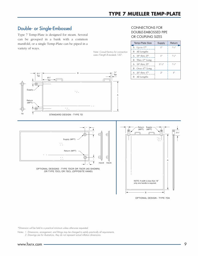
Double- or Single-EmbossedType 7 Temp-Plate is designed for steam. Several
can be grouped in a bank with a common
manifold, or a single Temp-Plate can be piped in a
variety of ways.
*Dimension will be held to a practical minimum unless otherwise requested.
Notes: 1. Dimensions, arrangement, and fittings may be changed to satisfy practically all requirements.2. Drawings are for illustrations, they do not represent actual inflation dimensions.
7D STANDARD DESIGN - TYPE 7D
Supply
Return(MPT)
3/4"Typ.
A
*
*
B31/2"Typ.
63/4"Typ.
OPTIONAL DESIGNS - TYPE 7DCR OR 7SCR (AS SHOWN) OR TYPE 7DCL OR 7SCL (OPPOSITE HAND)
Supply (MPT)
7SCR7DCR
Return (MPT)
*
*
*
*
OPTIONAL DESIGN - TYPE 7DA
* *
NOTE: If width is less than 18”only one handle is required.
Supply(MPT)
Return(MPT)
A
B
31/2"
CONNECTIONS FOR DOUBLE-EMBOSSED PIPE OR COUPLING SIZES
Note: Consult factory for connectionsizes if length B exceeds 143".
9
Temp-Plate Size Supply Return
A Up to 17" 1" 3/4"
B All Lengths
A 18" thru 25" 1" 3/4"
B Thru 47" Long
A 18" thru 25" 11/2" 3/4"
B Over 47" Long
A 26" thru 47" 2" 1"
B All Lengths

OPTIONAL DESIGN - TYPE 6DG (AS SHOWN BOTH VIEWS) OR TYPE 6SGR OR 6SGL (FITTINGS DEPICTED CORRECTLY IN END VIEWS ONLY)
STANDARD DESIGN - TYPE 6D (AS SHOWN BOTH VIEWS) OPTIONAL DESIGNS - TYPE 6SR OR 6SL (FITTINGS DEPICTED CORRECTLY IN END VIEWS ONLY)
6D
Return(MPT)elbow
* *
Supply(MPT)elbow
6SR 6SL
Supply (MPT)
Return (MPT)
31/2"Typ.
*
3/4"Typ.
Optional
*
A
63/4"
B
Return (MPT)31/2"
*
Supply(MPT)
*6DG
Return (MPT) elbow
* *
6SGL 6SGR
Supply (MPT) elbow31/2"
OPTIONAL DESIGNS - TYPE 6DCR OR 6SCR (AS SHOWN)OR TYPE 6DCL OR 6SCL (OPPOSITE HAND)
*Return (MPT)
Supply (MPT) 6SCR*
**
6DCR
OPTIONAL DESIGNS - TYPE 6DKR OR 6SKR (AS SHOWN)OR TYPE 6DKL OR 6SKL (OPPOSITE HAND)
6DKRSupply (MPT)
6SKR
*
*
*
*
Return (FPT)
TYPE 6 MUELLER TEMP-PLATE
10
Double-Embossed Single-EmbossedTemp-Plate Size Supply & Return Supply & Return
Double- or Single-EmbossedType 6 Temp-Plate is arranged for serpentine flow.
It is designed for increased velocities resulting in
accelerated heat transfer when using hot or cold
water, hot oil, flooded refrigerants, etc.
A Thru 25" 3/4" 1/2"
B All Lengths
A 26" thru 47" 1" 3/4"
B All Lengths
PIPE OR COUPLING SIZES
Note: Consult factory for connection sizes if length B exceeds 143".
*Dimension will be held to a practical minimum unless otherwise requested.
Notes: 1. Dimensions, arrangement, and fittings may be changed to satisfy practically all requirements.2. Number of passes will depend on design conditions.3. Drawings are for illustrations, they do not represent actual inflation dimensions.
TYPE 5 MUELLER TEMP-PLATE
www.hxrx.com
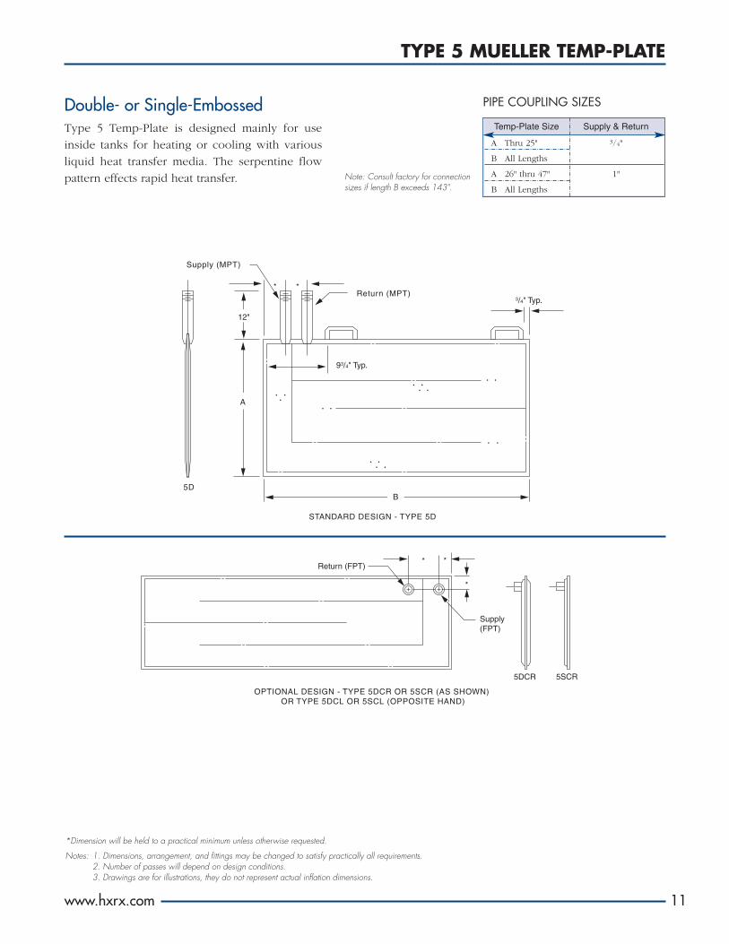
STANDARD DESIGN - TYPE 5D
OPTIONAL DESIGN - TYPE 5DCR OR 5SCR (AS SHOWN) OR TYPE 5DCL OR 5SCL (OPPOSITE HAND)
Return (FPT)
Supply(FPT)
5DCR 5SCR
* *
*
*
B
93/4" Typ.
Supply (MPT)
Return (MPT)3/4" Typ.
5D
*
12"
A
Note: Consult factory for connectionsizes if length B exceeds 143".
Double- or Single-EmbossedType 5 Temp-Plate is designed mainly for use
inside tanks for heating or cooling with various
liquid heat transfer media. The serpentine flow
pattern effects rapid heat transfer.
PIPE COUPLING SIZES
11
*Dimension will be held to a practical minimum unless otherwise requested.
Notes: 1. Dimensions, arrangement, and fittings may be changed to satisfy practically all requirements.2. Number of passes will depend on design conditions.3. Drawings are for illustrations, they do not represent actual inflation dimensions.
Temp-Plate Size Supply & Return
A Thru 25" 3/4"
B All Lengths
A 26" thru 47" 1"
B All Lengths
OPTIONAL FEATURES AND ACCESSORIES
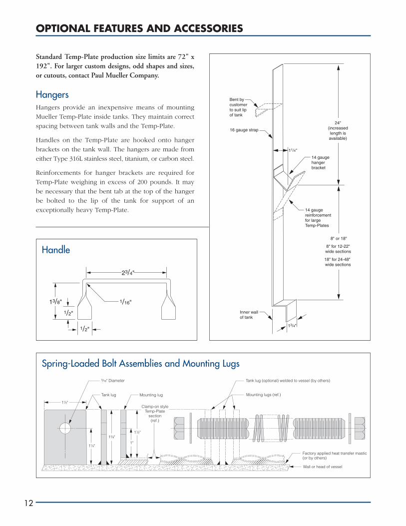
Standard Temp-Plate production size limits are 72" x192". For larger custom designs, odd shapes and sizes,or cutouts, contact Paul Mueller Company.
HangersHangers provide an inexpensive means of mounting
Mueller Temp-Plate inside tanks. They maintain correct
spacing between tank walls and the Temp-Plate.
Handles on the Temp-Plate are hooked onto hanger
brackets on the tank wall. The hangers are made from
either Type 316L stainless steel, titanium, or carbon steel.
Reinforcements for hanger brackets are required for
Temp-Plate weighing in excess of 200 pounds. It may
be necessary that the bent tab at the top of the hanger
be bolted to the lip of the tank for support of an
exceptionally heavy Temp-Plate.
12
1/16"13/8"
1/2"
1/2"
23/4"
Wall or head of vessel
Factory applied heat transfer mastic(or by others)
Clamp-on styleTemp-Plate
section(ref.)
Tank lug (optional) welded to vessel (by others)
Mounting lugs (ref.)
1½"
1½"
9⁄16" Diameter
Mounting lugTank lug
1"
13⁄4"
1¼"
Bent bycustomer to suit lip of tank
11/4"
14 gaugereinforcementfor largeTemp-Plates
13/4"
Inner wallof tank
16 gauge strap
8" or 18"
8" for 12-22"wide sections
18" for 24-48" wide sections
24"(increasedlength isavailable)
14 gaugehangerbracket
Spring-Loaded Bolt Assemblies and Mounting Lugs
Handle
MATERIALS, METAL THICKNESSES, AND DESIGN PRESSURES
www.hxrx.com
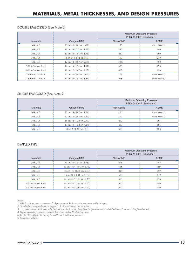
Maximum Operating Pressure PSIG @ 400°F (See Note 4)
Materials Gauges (MM) Non-ASME ASME
Maximum Operating Pressure PSIG @ 400°F (See Note 4)
Materials Gauges (MM) Non-ASME ASME
DOUBLE EMBOSSED (See Note 2)
DIMPLED TYPE
SINGLE EMBOSSED (See Note 2)
Notes:1. ASME code requires a minimum of 18-gauge metal thicknesses for resistance-welded designs.2. Standard circuiting is shown on pages 7-11. Special circuits are available.3. 1" is the maximum thickness for the heavier side of roll-formed Temp-Plate (single embossed) and dished Temp-Plate heads (single embossed).4. Higher operating pressures are available. Contact Paul Mueller Company.5. Contact Paul Mueller Company for ASME availability and pressures.6. Resistance welded.
304, 316 20 on 20 (.902 on .902) 170 (See Note 1)
304, 316 18 on 18 (1.22 on 1.22) 240 140
304, 316 16 on 16 (1.51 on 1.51) 450 190
304, 316 14 on 14 ( 1.91 on 1.91) 500 210
304, 316 12 on 12 (2.67 on 2.67) 1,000 400
A-620 Carbon Steel 14 on 14 (1.91 on 1.91) 633 273
A-620 Carbon Steel 12 on 12 (2.67 on 2.67) 665 290
Titanium, Grade 1 20 on 20 (.902 on .902) 175 (See Note 1)
Titanium, Grade 1 16 on 16 (1.51 on 1.51) 245 (See Note 5)
Maximum Operating Pressure PSIG @ 400°F (See Note 4)
Materials Gauges (MM) Non-ASME ASME
304, 316 16 on 10 (1.51 on 3.43) 275 1426
304, 316 16 on 3/16" (1.51 on 4.76) 325 1356
304, 316 16 on 1/4" (1.51 on 6.35) 325 1356
304, 316 14 on 10 ( 1.91 on 3.43) 400 142
304, 316 14 on 3/16" (1.91 on 4.76) 400 250
A-620 Carbon Steel 14 on 3/16" (1.91 on 4.76) 300 180
A-620 Carbon Steel 12 on 3/16" (2.67 on 4.76) 300 180
304, 316 20 on 14 (.902 on 1.91) 170 (See Note 1)
304, 316 20 on 12 (.902 on 2.67) 170 (See Note 1)
304, 316 18 on 12 (1.22 on 2.67) 400 185
304, 316 18 on 10 (1.22 on 3.43) 400 185
304, 316 18 on 7 (1.22 on 4.94) 400 185
13

NOTE: .082" Pillow1.5
1.0
0.5
02 4 6 8 10
Pre
ssur
e D
rop
(p
sig
per
foot
of t
rave
l)
Water Flow (gpm per foot of width)*
*Water pressure drop data for double-embossed Temp-Plate: 24 ga on 12 ga, 11/2" X 11/2" spot spacing
LEGEND.080 Inches of Pillow.109 Inches of Pillow.122 Inches of Pillow
2.0
1.5
1.0
0.5
05 10 15 20 25 30 35
* Water pressure drop data for double-embossed Temp-Plate: 16 ga on 16 ga, 17/8" X 17/8" spot spacing
Pre
ssur
e D
rop
(p
sig
per
foot
of t
rave
l)
Water Flow (gpm per foot of width)*
0
0.2
0.4
0.6
0.8
1.0
1.2
1.4
5 10 15 20 25 30 35 40 45
*Pressure drop of water in 1/4'-deep dimpled Temp-Plate
Pre
ssur
e D
rop
(p
sig
per
foot
of t
rave
l)
Water Flow (gpm per foot of width)*
PRESSURE DROP CURVES
14
Inflated Double-EmbossedPressure Drop Test 422
Dimpled Pressure Drop Test 329B
Single-Embossed Pressure Drop
Note: The pressure drop curves shown are for information only. For specific data to meet your requirements, consult Paul Mueller Company.

To Convert Into Multiply By
METRIC CONVERSION TABLE — GLOSSARY OF SYMBOLS
Length Feet Meters 0.3048
Inches Millimeters 25.40
Meters Feet 3.281
Millimeters Inches 0.03937
Area Square Feet Square Meters 0.09290
Square Meters Square Feet 10.76
Volume Gallons Hectoliters 0.03785
Gallons Liters 3.785
Hectoliters Gallons 26.42
Liters Gallons 0.2642
Weight Grams Pounds 0.002205
Kilograms Pounds 2.205
Pounds Grams 453.6
Pounds Kilograms 0.4536
Pressure Atmospheres Pounds/Square Inch 14.70
Bars Pounds/Square Inch 14.50
Pascal Pounds/Square Inch 0.000145
Pounds/Square Inch Pascal 6894.0
Pounds/Square Inch Atmospheres 0.06804
Pounds/Square Inch Bars 0.0649
Power Btuh Watts 0.2931
Horsepower Watts 745.7
Watts Btuh 3.4129
Watts Horsepower 0.001341
Energy Btuh Kilocalories 0.2520
Kilocalories BTU 3.968
Temperature Conversion °F = 9 °C + 32 °C = 5 (°F - 32)5 9
UNIT CONVERSION TABLE
GLOSSARY OF SYMBOLS
“k” = Wall thermal conductivity, Btu per (hr) (sq ft) (°F per ft)
x2 = Wall thickness, ft
“Q” = Total heat transfer, Btu
“q” = Time rate of heat transfer, Btu per hr
t.d. = Temperature difference or change of a material’s temperature, °F
▲t = Temperature difference at given instance on opposite sides of wall, °F
▲t1 = (GTD) Greatest temperature between product and medium for heating or cooling, °F
▲t2 = (LTD) Least temperature between product and medium for heating or cooling, °F
▲Tm = (LMTD) Log mean temperature difference, °F
t1 = Higher temperature, °F
t2 = Lower temperature, °F
“R” = Thermal resistance, (hr) (sq ft) (°F) per Btu
“A” = Area, sq ft
“V” = Total volume of vessel, cu ft
“x” = Insulating material thickness, ft
“U” = Overall heat transfer coefficient, Btu per (hr) (sq ft) (°F)
“cp” = Specific heat of product, Btu per (lb) (°F)
“W” = Total weight of product, lb
sp. gr. = Specific gravity (water equals 1.0)
ho = Film conductance (outside), Btu per (hr) (sq ft) (°F)
hi = Film conductance (inside), Btu per (hr) (sq ft) (°F)
Btuh = British thermal units per hour
www.hxrx.com 15

SOLVING HEAT TRANSFER PROBLEMS
16
What Is Heat Transfer?In general, heat transfer is the flow of heat from one
substance to another. The flow of heat is always from the
higher temperature to the lower temperature.
The general formula for heat transfer is Q = A x U x ▲t
(see Glossary of Symbols, page 15). Expressed in more
U= 1 or U = 1
1/ho + x2/k + 1/hi Summation ofresistance to heat flow
exact terms, with 1/ho equal to film resistance on one
side of a wall and 1/hi the film resistance on the other
side and x2/k the wall resistance between the films. It
should be noted that in most cases the film resistance will
be higher than the wall resistance.
Although it is possible to compute the “U” factor, it is an
involved process and the results are only accurate when
all of the controlling factors are considered. The usual
method to obtain a given “U” factor is to test the given
materials under normal conditions encountered in the
industry. Through extensive testing, the “U” factors given
in table (see page 20) are recommended for Temp-Plate
as safe design coefficients (i.e., scale deposits, film
factors, and vapor film coefficients have been taken into
account as well as a safety factor added).
Solving Heat Transfer ProblemsGenerally, in industrial applications, the equation Q = A
x U x ▲t is rewritten to establish “A”, the area required
to perform a given heat transfer job, and assumes the
form:
A = Q
U x ▲t
This equation can generally be solved in four steps, as
follows:
1. Determine “Q” where Q = V x (62.4 x sp. gr.)* x cp x t.d.:
V = Volume of vessel in cubic feet
cp = Specific heat of product
t.d. = t1 – t2 = Temperature change
*Can be expressed in pounds per cubic foot.
2. Determine “U” from Table on page 20.
3. Determine effective temperature difference “▲t.” In
actual practice and in order to obtain accuracy, in
place of “▲t” we use the log mean temperature
difference, ▲Tm. This can be computed by applying
the equation:
▲Tm = ▲t1 – ▲t2
In ▲t1
▲t2
but for simplicity, the ▲Tm (see page 21) can be used
for Temp-Plate, and by interpolation reasonable
accuracy can be obtained.
4. Solve equation A = Q
U x (▲Tm)
Note: The entire heat transfer solution as determined
in the preceding heat transfer steps can be solved
simultaneously by combining the entire formulas
from steps 1, 2, and 3 and solving for:
A = W x cp x t.d.
HRS x U x (▲Tm)
or if the area is known, the equation can be solved
for the time required. See Examples 1, 2, and 3.
HRS = W x cp x t.d.
A x U x (▲Tm)
Film (hi)
Film (ho)
Metallic wall (x2)
Liquid being heated
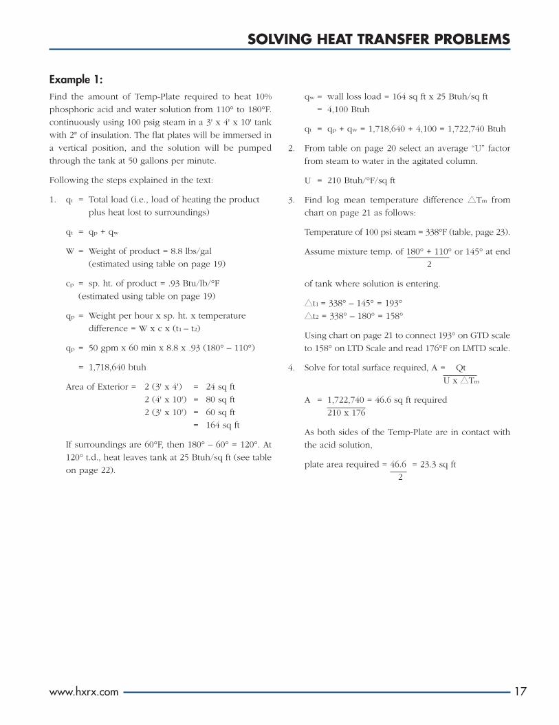
Example 1:Find the amount of Temp-Plate required to heat 10%
phosphoric acid and water solution from 110° to 180°F.
continuously using 100 psig steam in a 3' x 4' x 10' tank
with 2" of insulation. The flat plates will be immersed in
a vertical position, and the solution will be pumped
through the tank at 50 gallons per minute.
Following the steps explained in the text:
1. qt = Total load (i.e., load of heating the product
plus heat lost to surroundings)
qt = qp + qw
W = Weight of product = 8.8 lbs/gal
(estimated using table on page 19)
cp = sp. ht. of product = .93 Btu/lb/°F
(estimated using table on page 19)
qp = Weight per hour x sp. ht. x temperature
difference = W x c x (t1 – t2)
qp = 50 gpm x 60 min x 8.8 x .93 (180° – 110°)
= 1,718,640 btuh
Area of Exterior = 2 (3' x 4') = 24 sq ft
2 (4' x 10') = 80 sq ft
2 (3' x 10') = 60 sq ft
= 164 sq ft
If surroundings are 60°F, then 180° – 60° = 120°. At
120° t.d., heat leaves tank at 25 Btuh/sq ft (see table
on page 22).
qw = wall loss load = 164 sq ft x 25 Btuh/sq ft
= 4,100 Btuh
qt = qp + qw = 1,718,640 + 4,100 = 1,722,740 Btuh
2. From table on page 20 select an average “U” factor
from steam to water in the agitated column.
U = 210 Btuh/°F/sq ft
3. Find log mean temperature difference ▲Tm from
chart on page 21 as follows:
Temperature of 100 psi steam = 338°F (table, page 23).
Assume mixture temp. of 180° + 110° or 145° at end
2
of tank where solution is entering.
▲t1 = 338° – 145° = 193°
▲t2 = 338° – 180° = 158°
Using chart on page 21 to connect 193° on GTD scale
to 158° on LTD Scale and read 176°F on LMTD scale.
4. Solve for total surface required, A = Qt
U x ▲Tm
A = 1,722,740 = 46.6 sq ft required
210 x 176
As both sides of the Temp-Plate are in contact with
the acid solution,
plate area required = 46.6 = 23.3 sq ft
2
SOLVING HEAT TRANSFER PROBLEMS
www.hxrx.com 17

Example 2:Find the amount of Temp-Plate needed to cool 1,000
gallons of syrup (50° Brix sucrose solution) from 150° to
50°F in six hours. Temp-Plate will form the side walls of
the cylindrical tank holding the syrup, and the tank will
have 2" insulation. Water entering at 34°F will be
circulated in the Temp-Plate. The sugar solution will be
mechanically agitated. Tank dimensions are approximately
70" OD x 93" long.
Following the steps explained in the text:
1. W = Weight of product = 10.25 lbs/gal (see table
on page 19) = 1,000 x 10.25 = 10,250 lbs
c = sp. ht. of product = .65 Btu/lb/°F (see table
on page 19)
t.d. = 150° – 50° = 100°F
Product load, qp = 10,250 x .65 x 100 = 111,042
6
Exterior area = 195 sq ft
Assume 80°F ambient, then average temperature
difference = (150° + 50°) – 80° = 20°F
2
At 20° t.d., wall loss factor for 2" insulation = 4
Btuh/sq ft (see table on page 22)
Wall losses, qw = 4 x 195 = 780 Btuh
Note: As average product temperature is greater than
ambient, the 780 Btuh may be subtracted from the
average cooling required.
Total Load, qt = 111,042 – 780 = 110,262 Btuh
2. From table on page 20 select overall heat transfer
coefficient “U” of 60 Btuh/°F/sq ft (midway between
maximum and minimum shown for agitated
moderately viscous solution being cooled with water).
3. The greatest temperature difference at start is
150° – 34° = 116°. If the average temperature rise of
the water being circulated is assumed to be around
3°, we may use as the least temperature difference
50° – 37° = 13°. Find ▲Tm of 44° on chart, page 21.
4. A = qt = 110,262 = 41.8 sq ft
U x (▲Tm) 60 x 44
Example 3:Determine the amount of clamp-on Temp-Plate required
to hold an uninsulated 20,000-gallon tank of fuel oil at
40°F in ambient temperature that could go to -10°F
minimum. Use 15 psig steam as the heating medium. The
vessel is pad mounted, 12' diameter by 24' high. There is
no agitation.
Due to the relatively high thermal resistance at the inter-
face of the Temp-Plate and tank wall, low “U” factors are
expected. Assuming that a heat transfer mastic is used to
obtain better contact, then select “U” of 30 Btuh/°F/sq ft.
Surface area = 1,018 ft2 (ignore heat transfer on
bottom of pad-mounted vessel)
t.d. = 40 – (-10) = 50°F
Wall loss factor = 90 Btuh/sq ft (table on page 22)
Then qw = 90 x 1,018 = 91,620 Btuh
Steam temperature @ 15 psig = 250°F (table, page 23)
Then A = 91,620 = 14.54 sq ft
30 x (250 - 40)
Better performance would result, particularly on an
unagitated tank, if Temp-Plate is properly placed
completely around the vessel. This would require
approximately 38 sq ft if a one-foot-high band is utilized.
See table on page 22 for the benefit of using insulation.
18
SOLVING HEAT TRANSFER PROBLEMS

*Specific heat of water is one Btu per pound per degree Fahrenheit.
Specific Heat* Density
Name of Material State (Btu/Lb/°F) Lb/Cu Ft (Lb/Gal)
Acetic Acid Liquid .52 66 8.82
Air Gas .24 .08
Alcohol - Ethyl Liquid .55
Aluminum Solid .23 170
Asphalt Solid .4 80 10.70
Brine 20% CaCl2 Liquid .74 74.0 9.89
Brine 21% Liquid .81 72 9.63
Copper Solid .095 557
Cork Solid .49 15
Creosote Liquid .35 75 10.03
Dowtherm A Liquid .63 62 8.29
Dowtherm C Liquid .50 Avg. 69 9.22
Ethylene Glycol Liquid .58 70 9.36
Fuel Oil Liquid .40 60 8.02
Glue (Water Ratio 2/1) Liquid .9 68 9.09
Gasoline Liquid .5 38 5.08
Glass Solid .18 Avg. 175 Avg.
Hydrochloric Acid, 8° BE Liquid .75 66 8.82
Honey Liquid .35
Ice Cream (12% Solids) Liquid .8 71 9.49
Ice Solid .49 56
Iron Solid .1 445
Insulation: Glass Wool Solid .16 .3
Magnesia Solid .27 13
Cork Solid .49 15
Kerosene Liquid .5 51 6.82
Lard Solid .64 58
Lead Solid .03 710
Maple Syrup Liquid .49
Milk Liquid .93 64 8.6
Nitric Acid Liquid .76 66 8.82
Oil: Fuel (Bunker “C”) Liquid .40 59 7.89
Transformer, Medium Liquid .42 57 7.62
Cotton Seed Liquid .47 59 7.89
Linseed Liquid .44 58 7.75
Olive Liquid .47 57 7.62
Machine Liquid .40 58 7.75
Oleo Margarine Solid .28 Avg.
Paraffin Solid .62 56 Avg.
Phosphoric Acid (10%) Liquid 93 65.5 8.80
Refrigerant 113 Liquid .21 98 13.10
Seawater Liquid .94 64.3 8.57
Sodium Hydroxide (9% Solution) Liquid .91 68.5 9.16
Sugar Solution Liquid .3 104 13.90
Sugar Solution (50° Brix) Liquid .65 104 10.25
Steel Solid .12 487
Steel, Stainless Solid .12 501
Sulphur Solid .20 125
Turpentine Liquid .41 54 7.22
Tar, Coal Solid .40 75
Water Liquid 1.0 62.4 8.34
Wine Liquid .9 64 8.56
Zinc Solid .10 440
www.hxrx.com 19
PROPERTIES OF MATERIAL
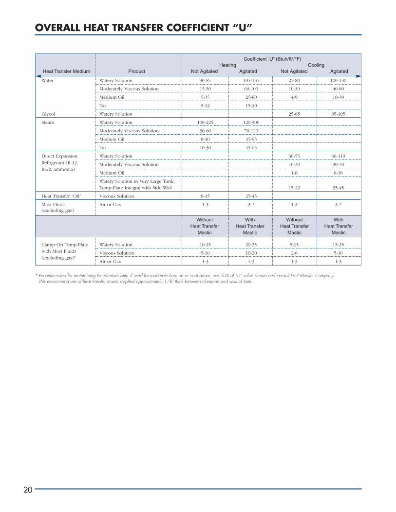
Coefficient “U” (Btuh/ft2/°F)Heating Cooling
Heat Transfer Medium Product Not Agitated Agitated Not Agitated Agitated
OVERALL HEAT TRANSFER COEFFICIENT “U”
20
Water Watery Solution 30-85 105-135 25-80 100-130
Moderately Viscous Solution 15-50 60-100 10-30 40-80
Medium Oil 5-35 25-80 4-9 10-30
Tar 5-12 15-20
Glycol Watery Solution 25-65 85-105
Steam Watery Solution 100-225 120-300
Moderately Viscous Solution 30-60 70-120
Medium Oil 8-40 35-95
Tar 10-30 45-65
Direct Expansion Watery Solution 30-55 60-110Refrigerant (R-12, Moderately Viscous Solution 10-30 30-70R-22, ammonia)
Medium Oil 1-8 6-18
Watery Solution in Very Large Tank,Temp-Plate Integral with Side Wall 15-22 35-45
Heat Transfer “Oil” Viscous Solution 8-15 25-45
Most Fluids Air or Gas 1-3 3-7 1-3 3-7(excluding gas)
Clamp-On Temp-Plate Watery Solution 10-25 20-35 5-15 15-25with Most Fluids Viscous Solution 5-10 10-20 2-6 5-10(excluding gas)*
Air or Gas 1-3 1-3 1-3 1-3
*Recommended for maintaining temperature only. If used for moderate heat up or cool down, use 50% of “U” value shown and consult Paul Mueller Company.We recommend use of heat transfer mastic applied approximately 1/8" thick between clamp-on and wall of tank.
Without With Without WithHeat Transfer Heat Transfer Heat Transfer Heat Transfer
Mastic Mastic Mastic Mastic

LMTD NOMOGRAPH
www.hxrx.com
LOGARITHMIC MEAN TEMPERATURE DIFFERENCE NOMOGRAPH
To find LMTD (Logarithmic Mean Temperature Difference), lay straight edge from greater temperature difference (left scale) to lesser temperature difference (right scale) andread LMTD on center scale.
20
30
40
50
60
70
80
90
100
150
200
250
300
10
9
8
7
6
5
4
LTD
t 2Le
ast T
empe
ratu
re D
iffer
ence
(LM
TD
) °F
LMTD
20
30
40
50
60
70
80
90100
150
200
250
300
400
109
8
7
6
t mLo
g M
ean
Tem
pera
ture
Diff
eren
ce (
LMT
D)
°F
GTD
10
20
30
40
50
60
70
8090
100
150
200
250
300
350
400
t 1G
reat
est T
empe
ratu
re D
iffer
ence
(G
TD
) °F
t 1 t 2
21

VESSEL SURFACE HEAT LOADS/REFRIGERANT PROPERTIES
22
*Difference in temperature between product in vessel and ambient air.**Heat transferred through tank walls.***Heat transferred to the room atmosphere from the horizontal liquid surface of uncovered tanks.Note: This chart is based on no air flow across fluid surface.
PROPERTIES OF SATURATED REFRIGERANTS
*Indicates vacuum (inches of mercury).
VESSEL SURFACE HEAT LOADS
Temp. Heat Load, Btuh/sq ft of tank wall area** Heat Load, Btuh/sq ft***Difference*
°F No Insulation 1" Insulation 2" Insulation 3" Insulation Water Surface Oil Surface
0 0 0 0 020 33 8 4 330 50 12 6 4 130 10040 70 15 8 6 230 13050 90 19 10 7 330 16060 110 23 12 9 470 20070 135 27 14 10 615 24080 160 31 17 12 820 27090 180 34 18 13 1,040 300
100 210 38 21 15 1,310 340110 235 42 23 16 1,615 370120 260 46 25 17 2,000 410130 290 50 27 19 2,450 450140 320 53 29 20 3,000 490150 350 57 31 22 3,590 530160 380 61 33 23 570190 690240 860340 1,360440 1,870
PSIG PSIGR-717 R-717
°F °C R-134a R-22 (Ammonia) °F °C R-134a R-22 (AMMONIA)
-50 -45.6 18.6* 6.0* 14.3* 24 -4.4 21.4 47.9 37.9-45 -42.8 16.7* 2.6* 11.7* 26 -3.3 22.9 50.2 40.2-40 -40.0 14.7* 0.6 8.7* 28 -2.2 24.5 52.7 42.6-35 -37.2 12.3* 2.7 5.4* 30 -1.1 26.1 55.2 45.0-30 -34.4 9.7* 5.0 1.6* 32 0 27.8 57.8 47.6-28 -33.3 8.6* 6.0 0.0 34 1.1 29.5 60.5 50.2-26 -32.2 7.4* 7.0 0.8 36 2.2 31.3 63.3 52.9-24 -31.1 6.2* 8.1 1.7 38 3.3 33.1 66.1 55.7-22 -30.0 4.9* 9.2 2.6 40 4.4 35.0 69.0 58.6-20 -28.9 3.6* 10.3 3.6 45 7.2 40.0 77.0 66.3-18 -27.8 2.2* 11.5 4.6 50 10.0 45.4 84.7 74.5-16 -26.7 0.7* 12.7 5.6 55 12.8 51.2 93.2 83.4-14 -25.6 0.4 13.9 6.7 60 15.6 57.4 102.5 92.9-12 -24.4 1.2 15.2 7.9 65 18.3 64.1 112.0 103.1-10 -23.3 2.0 16.6 9.0 70 21.1 71.1 122.5 114.1-8 -22.2 2.8 18.0 10.3 75 23.9 75.7 133.8 125.8-6 21.1 3.7 19.4 11.6 80 26.7 86.7 145.0 138.3-4 -20.0 4.6 20.9 12.9 85 29.4 95.2 158.0 151.7-2 -18.9 5.5 22.5 14.3 90 32.2 104.3 170.1 165.9-0 -17.8 6.5 24.1 15.7 95 35.0 114.0 184.8 181.12 -16.7 7.5 25.7 17.2 100 37.8 124.1 197.9 197.24 -15.6 8.6 27.4 18.8 105 40.6 135.0 213.1 214.26 -14.4 9.7 29.2 20.4 110 43.3 146.4 228.7 232.38 -13.3 10.8 31.0 22.1 115 46.1 158.4 246.0 251.5
10 -12.2 12.0 32.9 23.8 120 48.9 171.1 262.6 271.712 -11.1 13.2 34.9 25.6 125 51.7 184.5 280.5 293.114 -10.0 14.4 36.9 27.5 130 54.4 198.7 298.8 315.016 -8.9 15.7 39.0 29.4 135 57.2 213.5 317.9 335.018 -7.8 17.1 41.1 31.4 140 60.0 229.2 338.0 365.020 -6.7 18.4 43.3 33.5 145 62.8 245.6 359.6 390.022 -5.6 19.9 45.5 35.7 150 65.6 262.8 384.3 420.0

SATURATED STEAM PROPERTIES/STEAM REQUIREMENTS
www.hxrx.com
PROPERTIES OF SATURATED STEAM
STEAM REQUIREMENTS
Steam in lbs/hr = total load (1) boiler hp = 34.5 lbs steam/hrlatent heat of steam
Steam Required (lbs/hour) Steam Required (lbs/hour)Total Load Steam Pressure Total Load Steam Pressure
Btuh 15 psig 60 psig 100 psig Btuh 15 psig 60 psig 100 psig
100 .105 .111 .113 15,000 15.87 16.58 16.88
200 .212 .221 .225 20,000 21.16 22.14 22.54
500 .529 .553 .563 25,000 26.45 27.65 28.16
750 .794 .830 .845 30,000 31.74 33.18 33.79
1,000 1.05 1.11 1.13 40,000 42.33 44.25 45.05
1,500 1.59 1.66 1.69 50,000 52.91 55.31 56.31
2,000 2.12 2.21 2.25 75,000 79.36 82.96 84.47
2,500 2.65 2.77 2.82 100,000 105.78 110.66 112.75
3,000 3.17 3.32 3.38 250,000 264.62 276.56 281.68
4,000 4.23 4.42 4.50 500,000 529.10 553.09 563.07
5,000 5.29 5.53 5.63 750,000 793.66 829.64 844.63
6,000 6.35 6.64 6.76 1,000,000 1,058.20 1,106.19 1,126.13
7,000 7.41 7.74 7.88 1,250,000 1,322.75 1,382.74 1,407.66
8,000 8.47 8.85 9.01 1,500,000 1,587.30 1,659.29 1,689.10
9,000 9.52 9.96 10.14 1,750,000 1,851.85 1,935.84 1,970.72
10,000 10.57 11.06 11.27 2,000,000 2,116.40 2,212.39 2,252.25
Latent Heat ofPressure Temperature Heat of the Liquid Evaporation Total Heat of Steam Specific Volume
psig °F Btu/lb Btu/lb Btu/lb cu ft/lb
0.0 212.0 180.07 970.3 1,150.4 26.80
0.3 213.03 181.11 969.7 1,150.8 26.29
1.3 216.32 184.42 967.6 1,152.0 24.75
2.3 219.44 187.56 965.5 1,153.1 23.39
3.3 222.41 190.56 963.6 1,154.2 22.17
4.3 225.24 193.42 961.9 1,155.3 21.08
5.3 227.96 196.16 960.1 1,156.3 20.089
6.3 230.57 198.79 958.4 1,157.2 19.192
7.3 233.07 201.33 956.8 1,158.1 18.375
8.3 235.49 203.78 955.2 1,159.0 17.627
9.3 237.82 206.14 953.7 1,159.8 16.938
10.3 240.07 208.42 952.1 1,160.6 16.303
15.3 250.33 218.82 945.3 1,164.1 13.746
20.3 259.28 227.91 939.2 1,167.1 11.898
25.3 267.25 236.03 933.7 1,169.7 10.498
30.3 274.44 243.36 928.6 1,172.0 9.401
35.3 281.01 250.09 924.0 1,174.1 8.515
40.3 287.07 256.30 919.6 1,175.9 7.787
45.3 292.71 262.09 915.5 1,177.6 7.175
50.3 297.97 267.50 911.6 1,179.1 6.655
60.3 307.60 277.43 904.5 1,181.9 5.816
70.3 316.25 286.39 897.8 1,184.2 5.168
80.3 324.12 294.56 891.7 1,186.2 4.652
90.3 331.36 302.10 886.0 1,188.1 4.232
100.3 338.07 309.11 880.6 1,189.7 3.882
125.3 353.02 324.82 868.2 1,193.0 3.220
151.3 366.48 339.05 856.6 1,195.7 2.736
175.3 377.51 350.79 846.8 1,197.6 2.404
200.3 387.89 361.91 837.4 1,199.3 2.134
250.3 406.11 381.60 820.1 1,201.7 1.7422
23
HEATING APPLICATION CURVES
24
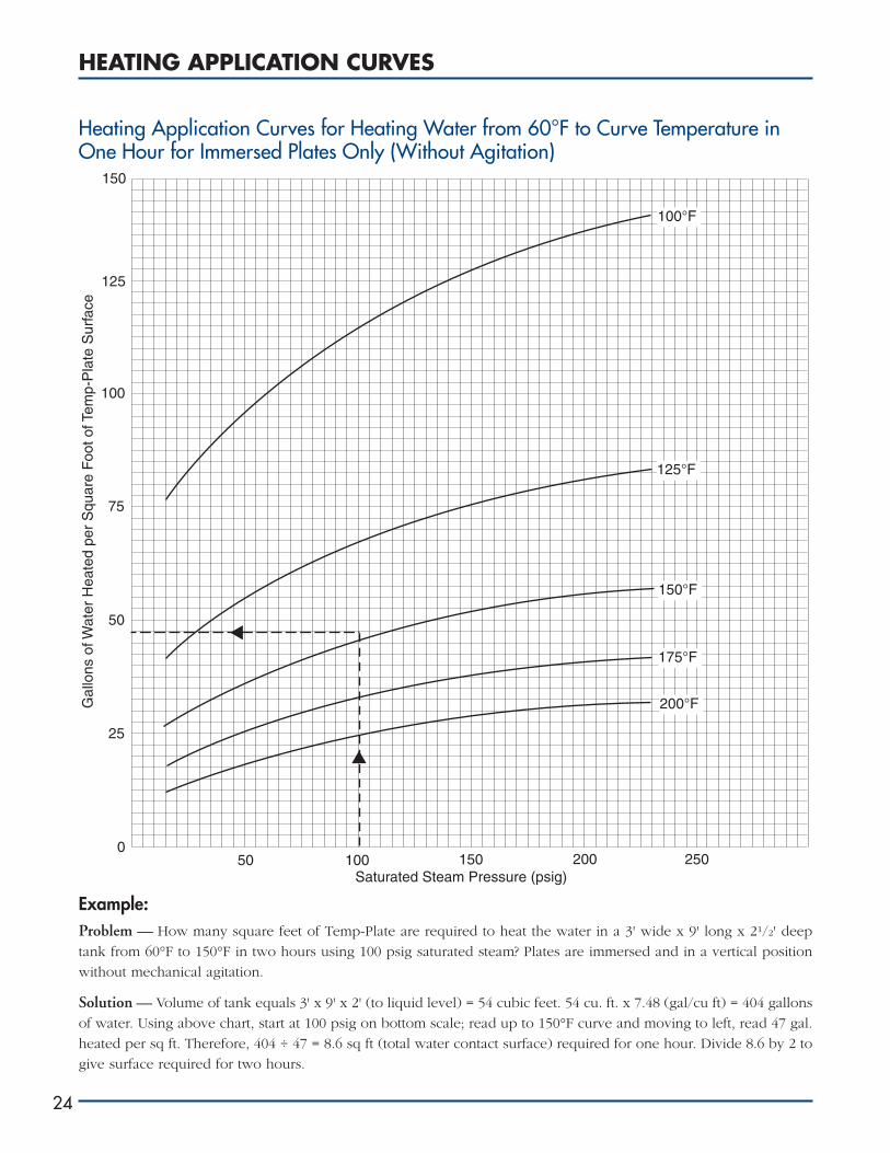
Heating Application Curves for Heating Water from 60°F to Curve Temperature inOne Hour for Immersed Plates Only (Without Agitation)
Example:Problem — How many square feet of Temp-Plate are required to heat the water in a 3' wide x 9' long x 21/2' deep
tank from 60°F to 150°F in two hours using 100 psig saturated steam? Plates are immersed and in a vertical position
without mechanical agitation.
Solution — Volume of tank equals 3' x 9' x 2' (to liquid level) = 54 cubic feet. 54 cu. ft. x 7.48 (gal/cu ft) = 404 gallons
of water. Using above chart, start at 100 psig on bottom scale; read up to 150°F curve and moving to left, read 47 gal.
heated per sq ft. Therefore, 404 ÷ 47 = 8.6 sq ft (total water contact surface) required for one hour. Divide 8.6 by 2 to
give surface required for two hours.
150
125
100
75
50
25
050 100 150 200 250
Saturated Steam Pressure (psig)
Gal
lons
of W
ater
Hea
ted
per
Squ
are
Foo
t of T
emp-
Pla
te S
urfa
ce
100°F
125°F
150°F
175°F
200°F

COOLING LOAD VS. WATER FLOW AND REFRIGERATION CAPACITY
www.hxrx.com
Water in gpm = total load Tons = Btuh60 x 8.34 x T.R.* 12,000
*Difference in temperature between water entering and leaving Temp-Plate passageways.
Water Required (gpm) Refrigeration Capacity
Total Load Water Temperature Change* (any refrigerant)Btuh 2° 4° 6° 8° 10° Tons
100 .1 .008
200 .2 .1 .017
500 .5 .25 .17 .042
750 .75 .38 .25 .063
1,000 1 .5 .3 .25 .083
1,500 1.5 .75 .5 .4 .3 .125
2,000 2 1 .7 .5 .4 .166
2,500 2.5 1.3 .8 .63 .5 .208
3,000 3 1.5 1 .75 .6 .250
4,000 4 2 1.4 1 .8 .333
5,000 5 2.5 1.7 1.3 1 .416
6,000 6 3 2 1.5 1.2 .500
7,000 7 3.5 2.4 1.8 1.4 .583
8,000 8 4 2.7 2 1.6 .667
9,000 9 4.5 3 2.3 1.8 .750
10,000 10 5 3.4 2.5 2 .833
15,000 15 7.5 5 3.8 3 1.250
20,000 20 10 6.7 5 4 1.667
25,000 25 12.5 8.4 6.3 5 2.083
30,000 30 15 10 7.5 6 2.500
40,000 40 20 13.3 10 8 3.333
50,000 50 25 16.7 12.5 10 4.167
75,000 75 37.5 25 18.8 15 6.250
100,000 100 50 33.4 25 20 8.333
250,000 250 125 83.4 62.5 50 20.833
500,000 500 250 166.7 125 100 41.667
750,000 750 375 250 188 160 62.500
1,000,000 1,000 500 333.3 250 200 83.333
1,250,000 1,250 625 416 313 250 104.167
1,500,000 1,500 750 500 375 300 125.000
1,750,000 1,750 875 583 438 350 145.833
2,000,000 2,000 1,000 666.6 500 400 166.667
25
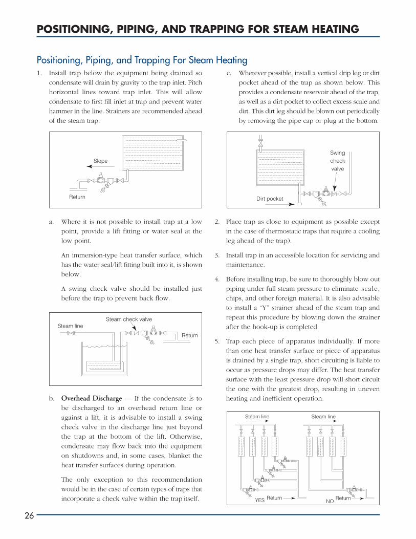
1. Install trap below the equipment being drained so
condensate will drain by gravity to the trap inlet. Pitch
horizontal lines toward trap inlet. This will allow
condensate to first fill inlet at trap and prevent water
hammer in the line. Strainers are recommended ahead
of the steam trap.
a. Where it is not possible to install trap at a low
point, provide a lift fitting or water seal at the
low point.
An immersion-type heat transfer surface, which
has the water seal/lift fitting built into it, is shown
below.
A swing check valve should be installed just
before the trap to prevent back flow.
b. Overhead Discharge — If the condensate is to
be discharged to an overhead return line or
against a lift, it is advisable to install a swing
check valve in the discharge line just beyond
the trap at the bottom of the lift. Otherwise,
condensate may flow back into the equipment
on shutdowns and, in some cases, blanket the
heat transfer surfaces during operation.
The only exception to this recommendation
would be in the case of certain types of traps that
incorporate a check valve within the trap itself.
c. Wherever possible, install a vertical drip leg or dirt
pocket ahead of the trap as shown below. This
provides a condensate reservoir ahead of the trap,
as well as a dirt pocket to collect excess scale and
dirt. This dirt leg should be blown out periodically
by removing the pipe cap or plug at the bottom.
2. Place trap as close to equipment as possible except
in the case of thermostatic traps that require a cooling
leg ahead of the trap).
3. Install trap in an accessible location for servicing and
maintenance.
4. Before installing trap, be sure to thoroughly blow out
piping under full steam pressure to eliminate scale,
chips, and other foreign material. It is also advisable
to install a “Y” strainer ahead of the steam trap and
repeat this procedure by blowing down the strainer
after the hook-up is completed.
5. Trap each piece of apparatus individually. If more
than one heat transfer surface or piece of apparatus
is drained by a single trap, short circuiting is liable to
occur as pressure drops may differ. The heat transfer
surface with the least pressure drop will short circuit
the one with the greatest drop, resulting in uneven
heating and inefficient operation.
POSITIONING, PIPING, AND TRAPPING FOR STEAM HEATING
26
Slope
Return
Steam lineSteam check valve
Return
Dirt pocket
Swingcheckvalve
Steam line
Return
Steam line
ReturnYES NO
Positioning, Piping, and Trapping For Steam Heating
6. Always use inlet and discharge piping at least as large
as the pipe connections in the trap.
7. When several traps discharge into a common header,
install a swing check valve between each trap and
the header to prevent reverse flow during shutdown
or possible blocking off of one trap by another when
they are discharging.
8. Bypasses have been largely eliminated nowadays due
to expense of installations and loss of steam when
left open by the operator. Where a bypass is necessary,
locate it at a higher level than the trap to avoid loss
of prime with bucket traps.
9. To allow for flash steam and prevent overloading,
discharge piping should be amply sized. For short
discharge lines, use pipe equal to trap size; for longer
lines, use one size larger.
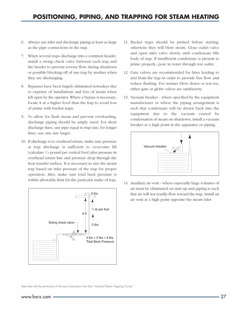
10. If discharge is to overhead return, make sure pressure
at trap discharge is sufficient to overcome lift
(calculate 1/2 pound per vertical foot) plus pressure in
overhead return line and pressure drop through the
heat transfer surface. It is necessary to size the steam
trap based on inlet pressure of the trap for proper
operation. Also, make sure total back pressure is
within allowable limit for the particular make of trap.
11. Bucket traps should be primed before starting;
otherwise they will blow steam. Close outlet valve
and open inlet valve slowly until condensate fills
body of trap. If insufficient condensate is present to
prime properly, pour in water through test outlet.
12. Gate valves are recommended for lines leading to
and from the trap in order to provide free flow and
reduce flashing. For strainer blow down or test tee,
either gate or globe valves are satisfactory.
13. Vacuum breaker - where specified by the equipment
manufacturer or where the piping arrangement is
such that condensate will be drawn back into the
equipment due to the vacuum caused by
condensation of steam on shutdown, install a vacuum
breaker at a high point in the apparatus or piping.
14. Auxiliary air vent - where especially large volumes of
air must be eliminated on start up and piping is such
that air will not readily flow toward the trap, install an
air vent at a high point opposite the steam inlet.
POSITIONING, PIPING, AND TRAPPING FOR STEAM HEATING
www.hxrx.com
Reprinted with the permission of Yarway Corporation from their “Industrial Steam Trapping Course.”
Swing check valve
3 lbs + 5 lbs = 8 lbsTotal Back Pressure
5 lbs
1/2 lb per foot
3 lbs
6 ft
27
Vacuum breaker
CLEANING, MAINTENANCE, AND REPAIRS
28
Temp-Plate is a well constructed, durable piece of
equipment, but the frequency with which it is subjected
to severe operating conditions demands that some
precautions must be taken. Proper choice of material for
a given application, in conjunction with a sensible
cleaning and maintenance program, will ensure
maximum performance and life.
There are two basic reasons for maintaining a clean
surface: corrosion prevention and minimizing heat
transfer resistance. Scale build-up on the surface reduces
the heat transfer rate significantly because of the poor
conductivity of the scale. The thermal resistance of the
scale can easily be an order of magnitude or greater than
the metal wall of the Temp-Plate itself.
Corrosion may be of a general or localized nature. Some
general corrosion may be acceptable based on economic
considerations involving more resistant materials and it
may occur on clean surfaces. However, it is possible that
a very resistant material in a given environment may have
localized corrosion problems due to contamination of the
surface. This is particularly true for stainless steel, which
apparently receives its corrosion resistance from a passive
film on the surface that occurs when clean stainless steel
is exposed to oxygen. Any barrier on the surface, such as
scale or dirt, inhibits this oxidation, with a resulting
reduction in corrosion resistance. Such conditions are
likely to cause pitting, a form of localized corrosion.
Other forms of localized corrosion are: intergranular,
crevice, galvanic, and stress corrosion cracking.
However, solutions to these problems have more basis
in proper choice of material, fabrication procedures, and
design, as well as care in the use of dissimilar metals than
in surface cleanliness. Initial considerations are important
here, and some assistance may be obtained by referring
to the Corrosion Section of this manual or numerous
other good references on corrosion. Improved surface
finish, such as that obtained by electropolishing, will
discourage scale build-up and the resulting problems.
Basically, the techniques for cleaning Temp-Plate are
chemical, mechanical, or a combination of these.
Mechanical cleaning may involve spraying with water
under high pressure, wire brushing, or direct blows to
the Temp-Plate to break the scale loose. The latter is not
recommended because carelessness could damage the
Temp-Plate; but if it must be done due to some
emergency, use a mallet of more resilient material (such
as leather) than that of Temp-Plate. Under no
circumstances should carbon steel tools or materials be
brought into contact with the stainless steel. Wire
brushing of stainless steel must be done with a stainless
steel brush.
The surface of inflated Temp-Plate, with its gentle,
pillowed effect, is relatively easy to clean, and swabbing,
brushing, or spraying are preferred cleaning procedures
when deposits are soft enough to be removed by these
methods. However, some applications, such as in the
metal finishing industry, lead to scale on the Temp-Plate
that requires the use of chemical cleaning. Precautions
must be taken, as chemicals effective for the scale
removal may induce corrosion on the Temp-Plate.
An acid solution that is safe at colder temperatures may
prove to have a detrimental effect on Temp-Plate at
higher temperatures. The variety of sources for problem
scale and the variety of materials used in construction of
Temp-Plate dictates that each application be considered
specifically. Suppliers of chemicals used in processes that
produce scale should be good consultants regarding
logical choices of chemicals and procedures to employ
for scale removal.
A regular cleaning program is of paramount importance,
but if loss of production due to downtime is a major
factor, it may be economically wise to invest in an extra
Temp-Plate so that production and cleaning can occur
simultaneously. This could be accomplished by
alternating production between two systems or rotating
Temp-Plate within a system on a scheduled basis.
Temp-Plate — Cleaning and Maintenance

The following repair techniques are recommended
whenever defects arise due to accidental damage, such as
leaks, etc.:
1. PRIOR TO REPAIR:Remove any contamination that might be present in
the defect area. There are various solvents and/or
mechanical means (grinding, brushings, etc.) that are
effective in removing this foreign matter. After initial
area cleaning, the defect itself needs to be removed to
assure that good sound metal is present. Once good
metal is reached, proceed with the weld repairs.
2. WELD REPAIR INFORMATION:A. Temp-Plate, Stainless Steel — Normally one of
the conventional welding processes is used for
repairing defects.
(1) For Type 304 stainless, use one of the
following:
a. Manual Shielded Metal Arc Welding
(SMAW, stick): Use either 3/32" or 1/8"
diameter E308-16 (AC-DC) electrode per
AWS A5.4 specifications.
b. Semi-Automatic Gas Metal Arc Welding
(GMAW, short arc, MIG): Use .035"
diameter or .045" ER308-type filler wire
meeting AWS A5.9 specifications.
c. Manual Gas Tungsten Arc Welding
(GTAW - TIG - heliarc): Use 1/16" or 3/32"
diameter ER308 bare filler rod meeting
AWS 5.9 specifications.
(2) For Type 316 stainless, use one of the
following:
a. SMAW Process: Use 3/32" or 1/8" diameter
ER316-16 (AC-DC) electrodes meeting
AWS A5.4 specifications.
b. GMAW Process: Use .035" or .045
diameter ER316-type filler wire meeting
AWS A5.9.
c. GTAW Process: use 1/16" or 3/32"
diameter ER316 bare filler rod meeting
AWS A5.9 specifications.
(3) For low-carbon grades stainless steel base
materials, use L-grade-type filler metal to
match the corrosion resistant characteristics.
(4) For austenitic stainless steel, the weld deposit
must be cooled to below 800°F within one
minute after welding in order to keep the
carbide precipitation to a minimum.
B . Temp-Plate, Carbon Steel — The conventional
method normally selected is the Shielded Metal
Arc Welding process (SMAW - stick). The all-
position electrodes E60XX or E70XX series, AWS
A5.1-type electrodes are generally recommended.
A typical selection would be an 1/8" diameter, AC
or DC reverse polarity electrode.
C. Temp-Plate, Other Alloy Materials — Contact
Paul Mueller Company personnel on such repairs
or with the original manufacturer of that grade
of material.
3. AFTER WELD REPAIR IS COMPLETED:A general cleaning, either mechanical or with
chemical solvents, should be done to remove any
contaminants remaining. Paul Mueller Company’s
pickling paste is recommended for removing weld
surface oxides and restoring corrosion resistance on
stainless steel Temp-Plate.
CLEANING, MAINTENANCE, AND REPAIRS
www.hxrx.com 29
Temp-Plate — Repairs
THERMAL EXPANSION
30
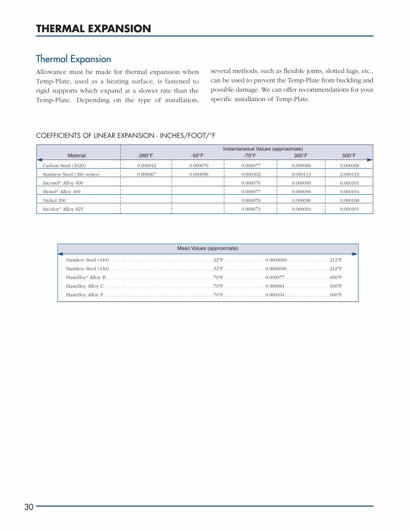
Thermal ExpansionAllowance must be made for thermal expansion when
Temp-Plate, used as a heating surface, is fastened to
rigid supports which expand at a slower rate than the
Temp-Plate. Depending on the type of installation,
several methods, such as flexible joints, slotted lugs, etc.,
can be used to prevent the Temp-Plate from buckling and
possible damage. We can offer recommendations for your
specific installation of Temp-Plate.
COEFFICIENTS OF LINEAR EXPANSION - INCHES/FOOT/°F
Mean Values (approximate)
Instantaneous Values (approximate)Material -260°F -50°F -70°F 300°F 500°F
Carbon Steel (1020) 0.000042 0.000070 0.000077 0.000086 0.000098
Stainless Steel (300 series) 0.000067 0.000098 0.000102 0.000113 0.000119
Inconel® Alloy 600 0.000070 0.000090 0.000101
Monel® Alloy 400 0.000077 0.000096 0.000104
Nickel 200 0.000070 0.000096 0.000108
Incoloy® Alloy 825 0.000073 0.000094 0.000101
Stainless Steel (410) . . . . . . . . . . . . . . . . . . . . . . . . . . . . . . . . . . .32°F . . . . . . . . . . . . . . 0.0000660 . . . . . . . . . . . . . . 212°F
Stainless Steel (430) . . . . . . . . . . . . . . . . . . . . . . . . . . . . . . . . . . .32°F . . . . . . . . . . . . . . 0.0000696 . . . . . . . . . . . . . . 212°F
Hastelloy® Alloy B . . . . . . . . . . . . . . . . . . . . . . . . . . . . . . . . . . . . .70°F . . . . . . . . . . . . . . 0.000077 . . . . . . . . . . . . . . . 600°F
Hastelloy Alloy C . . . . . . . . . . . . . . . . . . . . . . . . . . . . . . . . . . . . .70°F . . . . . . . . . . . . . . 0.000084 . . . . . . . . . . . . . . . 600°F
Hastelloy Alloy F . . . . . . . . . . . . . . . . . . . . . . . . . . . . . . . . . . . . .70°F . . . . . . . . . . . . . . 0.000104 . . . . . . . . . . . . . . . 600°F

THERMAL EXPANSION
www.hxrx.com
20 40 60 80 100
20 40 60 80 100
350 662
300
250 482
212
175 347
150
125 257
100 212
75 167
50
25 77
°C °F Percent Concentration in Water
31
Corrosion Resistance TableThis table shows the resistance of a number of materials
to the more common chemicals. Many factors influence
the resistance of materials to various solutions. Factors
which must be given consideration for service in
corrosive environments are: temperature, concentration,
aeration, influence of recirculation, solids in suspension,
velocity, frequency of use, and equipment design.
The influence of contaminants is probably the most
important from a commercial standpoint. Few corrosive
solutions will be free of all contaminants. The majority of
these contaminants have no influence on corrosion, but
those that do generally affect the conditions greatly.
The corrosion data for all grades except Alloy 20 is
reprinted from Corrosion Data Survey, 1974 Edition,
published by the National Association of Corrosion
Engineers. The corrosion rates for Alloy 20 represent a
composite of the NACE Corrosion Data Survey and more
current data developed in CarTech’s Corrosion
Laboratory.
Your process may require a specific material type for
proper corrosion protection. Contact a consulting
metallurgist for a recommendation.
Paul Mueller Company is not responsible for corrosion orsuitability for use of any material in any particularapplication! The corrosion resistance and suitability foruse of a material is dependent on operating environmentand conditions, cleaning practices, and many otherfactors beyond the control of the equipment fabricator.The user of the equipment bears total responsibility forcorrosion or suitability for use of all materials in theirparticular application!
Code● Corrosion rate less than 0.002" per year
❍ Corrosion rate less than 0.020" per year
❏ Corrosion rate from 0.020" to 0.050" per year
✕ Corrosion rate greater than 0.050" per year

32*Hastelloy B and Hastelloy C are registered trademarks of Cabot Corporation. **Monel is a registered trademark of International Nickel Company.

www.hxrx.com 33

34

www.hxrx.com 35

36

FOOTNOTES -CORROSIVES1 Poison2 Toxic3 Explosive4 Flammable5 Ingestion poison6 Inhalant poison7 Attacks skin8 Irritant9 Vapor harmful10 Ignites organics11 Fuming liquid12 Hygroscopic13 Liberates HCl in water14 Narcotic15 Volatile16 Hazardous under
pressure17 Ignites combustibles18 Fire Hazard19 Explosive over 70%20 Ignites in moist air at
30°C21 Exothermic in water22 Dust explodes23 Explosive dust24 Exothermic with water
FOOTNOTES -DATA SQUARES1 No water2 No air, oxygen3 Low air, oxygen4 Pits5 Stress cracks6 Stress corrosion7 Discolors8 Crevice attack9 Intergranular attack10 No chlorides
11 May discolor12 May catalyze13 May pit14 May stress crack15 Transgranular attack16 Vapor17 Aerated18 Catalyzes19 Static20 Agitated21 ˜7 pH22 <7 pH23 >7 pH24 No HCl, H2SO4, NaCl25 No ferric chloride26 ˜0.1% acetic acid27 Also sludge28 No iron salts29 No sulfuric acid30 Explosive31 With H2SO4
32 With steam33 No sulfur34 No stress35 No ammonia36 300 psi37 Stress relieved38 No HCl, Cu, Fe ions39 No Cu, Ni ions40 Over 70% air41 20-70% air, 530 psi42 With sulfur <340°C
= x43 <10 mg/144 No H2SO4
45 <60 psi46 No sulfides47 <20% zinc 48 Trace HCl49 pH 2 to 3 550 Annealed, immersed
51 >2.25% Mo52 Erratic53 With NaCl54 With NaCl, HCl,
H2O2
55 No Fe, Cl 56 With +˜0.05-1%
H3PO4 or H2SO4
57 +SO2 or HCOOH58 <RC 22, 60,00059 Annealed60 No cold work61 No H2S62 Permeable to H2
63 Unsulfated64 With or without steam65 240 psi66 Cold worked67 >80% copper68 >20% sulfuric, bal.
nitric acid69 No Mo; low C70 Red fuming71 Pits in chlorides72 Over 400°C73 Steam and air74 75-100% concentration75 Low NaCl76 With HCl77 <17% zinc 78 <0.23%, 200 psi79 300 psi80 No SO3
81 No NaCl82 High pressure83 75-120 psi84 No sodium sulfite85 + ammonia86 Avoid hydroxides87 Saturated
www.hxrx.com 37

THE PROBLEMS OF CORROSION
38
The engineer, metallurgist, or chemist with the problemof developing a product or designing a machine orstructure subject to corrosive conditions must know howcorrosion works and its relation to all types of metals andalloys that are commercially available. Only then will themost satisfactory and economical results be assured. Thisinformation may be classified in relation to the followingfactors:
1. Cost of original installation, including raw materialsand fabrication. The corrosive-resistant metals mayrange in cost from that of noble metals (gold,platinum, silver, etc.) down to that of common metalssuch as tin, lead, and ordinary iron. Methods offabrication may involve welding, riveting, forming,spinning, machining, etc.
2. Availability of the metals which would solve theproblem.
3. The type of corrosion likely to be encountered andthe rate of attack which can be allowed. This can beroughly divided into three classes:
a. Conditions in which color, taste, or odor of thefinal product are of most importance. This isencountered in the chemical, food, beverage,dairy, and other similar industries, and the metalsused must be highly resistant to corrosion fromthe products that are handled.
b. Parts for display or ornamental purposes wheresurface appearance of the finished part is of mostimportance and freedom from discoloration isvital.
c. Parts used in industry which must remainphysically intact over economical periods ofservice operation and in which the rate ofcorrosion and the life of the assembly are ofmost interest.
Stainless steel, in its many ramifications of alloy contentwhich impart varying degrees of corrosion resistance andphysical properties, has proved to be an engineering toolthat meets a wide variety of conditions just mentioned.
It is primarily an alloy of iron and chromium, a minimumof about 12% chromium being necessary to meetcorrosive-resistant requirements. In addition to iron andchromium, copper and molybdenum are sometimesadded to improve corrosive-resistant qualities. Nickel isalso added to improve corrosion resistance, provide
strength at elevated temperatures and ease fabrication.The chromium-iron alloys without nickel (Alloy 20) offerample protection for many types of applications and ingeneral are the least expensive to buy. However, onmany jobs, the fabricating requirements or corrosiveconditions may be such that alloys of chromium andnickel will be most economical. These chrome-nickelalloys (Alloy 20) contain chromium in percentages from16 to 25 and nickel from 7 up to as high as 20%. Theseaustenitic stainless steels are non-magnetic and arecharacterized by high ductility. They are not susceptibleto improvement in physical properties by heattreatment but can be so improved by cold working. Forextreme corrosive conditions, the resistance of thechrome-nickel alloys is further enhanced by the additionof molybdenum (i.e., Alloy 20. Titanium and columbiumis added to Alloy 20 to eliminate carbide precipitation).
There is another group of alloys containing approxi-mately 30% nickel, 20% chromium with additions ofcopper, molybdenum, and silicon that is superior to the18-8-type alloys in handling sulphuric acid, hot aceticacid, crude phosphoric acid, etc. One such alloy is Alloy20, a non-magnetic alloy with the same high strength andductility characteristics of the 18-8 alloys.
Types of CorrosionSome of the types of corrosion that may be encounteredin the use of stainless steels are:
Intergranular corrosionGalvanic corrosionConcentration cell corrosionGeneral corrosionPitting corrosionStress corrosion cracking
An understanding of the types of corrosion and how theyoccur can prevent expensive equipment failures if theyare considered when equipment is designed andconstruction materials specified.
Stainless steels are inherently corrosion resistant becauseof their ability to form a protective coating on theirsurfaces. This protective coating is commonly called a“passive film.” Corrosion theory does not agree as towhether this “passive film” is an absorbed layer of oxygenor an invisible oxide coating. When the “passive film” ispenetrated, corrosive attack develops at a point on thesurface.

1. Intergranular corrosion of stainless steels is confined
solely to the non-magnetic chrome-nickel-type steels
of Group “C” with the exception of the stabilized
grades and Alloy 20. Briefly, the non-stabilized
austenitic chrome-nickel grades, when heated in (or
cooled slowly through) the temperature range
between 800° and 1,650°F, tend to deposit carbide in
the grain boundaries. Under these conditions, the
transformed grain boundary areas are subject to
attack under some conditions of service. For
example, in the processes of welding, there is a
“transformation zone” in proximity to the weld. This
area is more subject to attack from intergranular
corrosion than either the weld metal itself or the
balance of the assembly.
Such difficulty can be avoided by two procedures:
a. By giving the welded assembly a heat treatment
after welding. This treatment consists of heating
to a temperature of 1,750 to 2,050°F, depending
upon the exact composition of the alloy, then
rapidly cooling to room temperature.
b. By using Alloy 20 chrome-nickel stainless steels
for the assembly. These grades are resistant to
carbide precipitation and can be used in the as-
welded conditions. For continuous service in
temperatures from 800° to 1,650°F, columbium
and tantalum or titanium stabilized alloys are
suggested.
Chrome-nickel stainless steels, unless otherwise
specified, are in the annealed condition and will
be entirely free from susceptibility to inter-
granular corrosion. The above precautions
should be observed in connection with the
fabrication of parts by welding and should be
taken into account in the use of parts which are
exposed to elevated temperatures in service.
2. Galvanic corrosion is common to all metals. This is
brought about when two dissimilar metals are in
contact in a liquid capable of carrying electric current.
This includes practically all aqueous solutions. Under
these conditions, an electric current is set up through
the solution and tends to accelerate the corrosion of
one of the metals and protect the other. For example,
where both copper or copper alloys and stainless
steel are in intimate contact in a solution of salt water,
the current will tend to accelerate the attack upon the
stainless steel portion and lessen the attack upon the
copper alloys. In general, the corrosion resistance of
stainless is reduced when in contact with lead, nickel,
copper, copper alloys, or graphite. On the other hand,
it is improved at the expense of the other metal when
in contact with iron, steel, aluminum, zinc, or
cadmium. The solution to this problem lies in using,
so far as possible, metals of the same composition for
complete assemblies when this condition is
encountered. In some cases, an insulating lacquer can
be used to form a separation between the two metals
at the point of contact.
The list that follows shows the galvanic behavior of
stainless steels with other metals when tested in
seawater.
THE PROBLEMS OF CORROSION
www.hxrx.com 39
GALVANIC SERIES OF METALS AND ALLOYSCorroded End (anodic, or at least noble)MagnesiumMagnesium AlloysZincAluminumCadmiumSteel or IronCast IronChromium-Iron (active)118-8 Chromium-Nickel-Iron (active)118-8-3 Chromium-Nickel-Molybdenum-Iron (active)1Alloy 20Titanium (active)Lead-Tin SoldersLeadTinNickel (active)1BrassesCopperBronzesCopper-Nickel AlloysSilver SolderNickel (passive)1Chromium-Iron (passive)118-8 Chromium-Nickel-Iron (passive)118-8-3 Chromium-Nickel-Molybdenum- Iron (passive)1Alloy 20Titanium (passive)SilverGraphiteZirconiumGoldPlatinumProtected End (cathodic, or most noble)
1Stainless is “active” in the presence of any combination of chemicals whichare reducing and do not allow the formation of an oxide film. A “passive”condition is obtained when the surface of a stainless part had developed theprotective oxide film. Treating stainless steels in a passivating solution willaccelerate the formation of the film.

THE PROBLEMS OF CORROSION
40
3. Concentration cell corrosion is somewhat similar to
galvanic corrosion in that it is caused by an electric
current set up between various parts of the same
vessel in which different concentrations of the
corrodent exist. This type of corrosion is often
associated with crevices such as the space between
loosely joined plates or gaskets. The corrodent in
such areas tends to stagnate, which causes an
increase in ionization. The difference in potential
between these spots and adjacent areas is so great
that current begins to flow. The stagnant area being
anodic soon shows signs of corrosion. This type of
trouble can usually be avoided by welding joints or
sealing them by caulking.
4. General corrosion: Under ordinary conditions of
service at normal temperatures, stainless steels are
immune to corrosion by the atmosphere. However,
in polluted atmospheres (particularly in hot climates)
corrosion is sometimes encountered. Under these
conditions, the most corrosion resistant of stainless
steels should be employed. The alloys containing
chromium, nickel, and molybdenum (Alloy 20) are
particularly recommended. In oxidizing atmospheres
at elevated temperatures, scaling may be encountered.
Stainless steels have a much lower rate of scale
formation than ordinary steels. The degree of scaling
at a given temperature depends upon the exact
composition of the stainless steels employed and the
composition of the atmosphere to which the metal is
exposed. In a general way, the higher the chromium
content, the greater the degree of scale resistance. It
has been found by experience that repeated heating
and cooling cycles are much more damaging than
continuous heating. In applying the chrome-nickel
stainless alloys (Alloy 20) to high temperature service,
the problem of intergranular corrosion described
previously should be taken into consideration.
5. Pitting: Under certain conditions of service, stainless
steels which are apparently immune to attack by
certain solutions will fail by corroding deeply in
individual spots. This type of failure is known as “pit”
corrosion. All the causes and correctives of this
condition are not well understood at the present
time, but several factors are known to accelerate it.
The presence of bruises, dents, rough spots, nicks,
and foreign deposits on the metal could conceivably
promote the formation of pits. If the “protective film”
were broken, a pit might start at this point. A pit once
formed becomes a concentration cell, and the
corrosion is accelerated at this point. In general, the
answer when this condition occurs would indicate
the selection of a stainless steel having a higher
degree of corrosion resistance than that in which the
pitting has been encountered. Molybdenum-bearing
grades, namely, Alloy 20, are less susceptible to
pitting. When pitting occurs, a careful examination
of operating conditions is essential.
6. Stress corrosion cracking: As the name suggests, this
form of corrosive attack results from the combination
of a selected corrosive environment and stresses in
the material. Both ferrous and non-ferrous alloys are
subject to stress corrosion cracking. The stresses may
result from cold working, quenching after heat
treatment, or from an externally applied stress. As
mentioned previously, the environment to promote
stress corrosion cracking is very selective. Chloride-
containing solutions or vapors usually promote this
type of failure in austenitic stainless steels.
Stress corrosion cracking may be minimized by
reducing fabrication stresses, removing harmful
contaminants from the environment, or selecting
materials which are resistant to this type of failure.

Factors Affecting CorrosionSome of the factors that influence corrosion, other than
the composition of the metal and corrodent itself, are as
follows:
1. The presence of impurities in the corrosive medium.
Inasmuch as pure chemicals or solutions are seldom
encountered in commercial work, the presence of
even minor percentages of impurities is of most
importance and should be considered when using
published corrosion tables.
2. The temperature of the corrodent. As a rule, the degree
of corrosion increases with increase in temperature.
There are numerous cases where metals satisfactory for
cold solutions are entirely unsuitable for these same
solutions at more elevated temperatures.
3. The degree of aeration to which a corrodent is
exposed. Liquids kept in closed containers from
which air or a circulation of air is excluded will cause
different degrees of corrosion than these same liquids
when freely exposed to the atmosphere. This applies
also to the presence of atmospheric gases which may
sometimes change the corrosive behavior of metals
to a marked degree.
4. Velocity of corrodent. Since published corrosion
tables are usually based on static tests, the corrosion
actual service may differ due to the effect of the
velocity.
Importance of PassivatingThe corrosive-resistant qualities of stainless steels are
inherent in the metal itself. However, the contamination
of the surface by adhering dirt or scale will have a
deleterious effect. For this reason, it is essential that all
scale be completely removed and the parts be kept clean
while in service.
THE PROBLEMS OF CORROSION
www.hxrx.com 41

PRODUCT APPLICATIONS
42
Mueller Temp-Plate heat transfer surface,which provides for efficient heating orcooling of a product, is used by thefollowing industries:
Aerospace Aircraft
Aluminum Appliance
Automotive Beverage
Chemical Cosmetic
Dairy Engineering Firms
Film Food Processing
Glass Ice-making
Laundries Meat Packing
Metal Finishing Nuclear Power
Pharmaceutical Plating
Pulp and Paper Steel
Sugar Textile
University Laboratories Utilities
Inflated Temp-Plate bank assembly for heat recovery from hot gas.
Inflated Temp-Plate cone sections.

Temp-Plate heat transfer surface has multiple applications in industries. Paul Mueller Company manufactures Temp-Plate in a great variety of styles, sizes, and materials for a multitude of purposes. For example:
• Banks of Temp-Plate for: cooling coffee extract, cooling quench
oil, cooling waste water while heating make-up water, cooling
water for fish hatcheries, heating a city’s water supply with boiler
condenser water, heating lard, separating moisture from crude oil
• Circular flat sections for inside bottoms of processing tanks
• Clamp-on sections for shells, cones, and heads
• Cooling cone for aerospace program
• Cooling shell sections for field-erected brewery fermenting tanks
• Cryogenic shrouds for mirror fusion energy
• Drying shelves for textiles and pharmaceuticals
• Evaporator pans for paper producers
• Frost and steam pans for cafeteria lines
• Fluidized bed dryers
• Freeze-drying shelves
• Ice-making plates
• Immersion sections for: brine chilling, chilling wine, cooling
anodizing solutions, drying powdered milk, heating spray
phosphate tanks, heating or cooling metal cleaning and plating
tanks, heating wire drawing solutions, ore recovery
• Internal baffles for tanks with agitators
• Interior cooling sections for yeast propagators
• Jacketed cylinders
• Jacketed heads and cones
• Jacketed troughs
• Large internal baffle assemblies for cooling vegetable oil
• Liquid natural gas vaporizers
• Liquid oxygen vaporizers
• Pan sections for cooling candy
• Tank covers
• Trough sections for cooking foods
• Vacuum drums
• Water chillers
www.hxrx.com
Inflated Temp-Plate troughs for poultry industry.
Temp-Plate bank assembly.
Inflated/dimpled Temp-Plate chute assembly.
43
PRODUCT APPLICATIONS

44
Baffles
BankAssemblies
Single Plates
IMMERSION SECTIONS
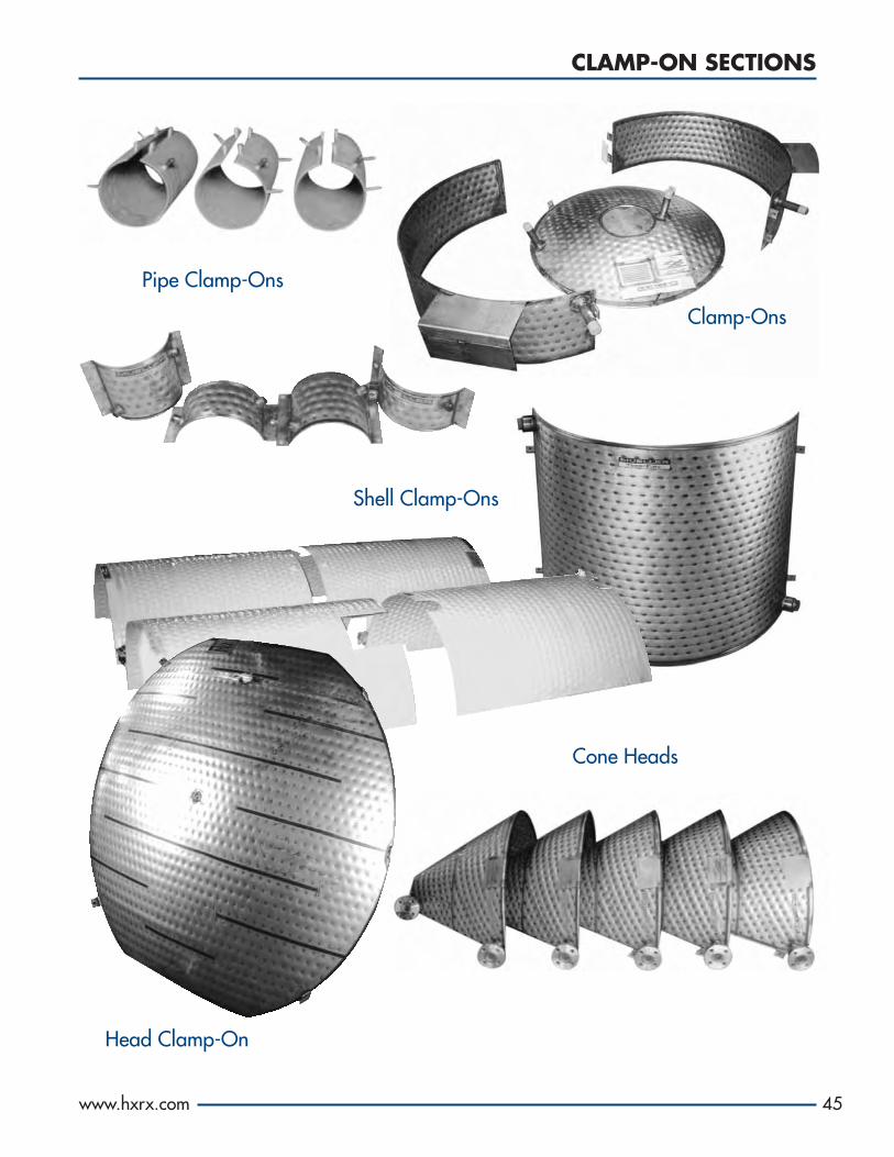
CLAMP-ON SECTIONS
www.hxrx.com
Shell Clamp-Ons
Head Clamp-On
Pipe Clamp-Ons
Clamp-Ons
Cone Heads
45

46
JACKETED SHELL AND HEAD SECTIONS

SUPPLIED FOR USE AN AS INTEGRAL PART OF A VESSEL
www.hxrx.com
Jacketed Head
Jacketed Trough
Jacketed Cylinders
47

SPECIAL APPLICATIONS
48
Hopper
SpecialPans
Food Cooker
Heat Shields

SPECIAL APPLICATIONS
www.hxrx.com 49
Cooling Shrouds
Heat RecoveryBank Assembly
Insertion Heaters
Flat Clamp-Ons
Calandria

ENERGY CONSERVATION
50
Energy Bank
Cryogenic Shrouds for Mirror Fusion
Cooling Waste Water WhilePreheating Make-Up Water
Falling FilmCryogenic Vaporizer

FOOD SERVICE DISPLAY UNITS
www.hxrx.com
ContinuousCooker Shell
Two-Level SaladDisplay Unit
Salad Display Unit
“Lazy Susan”Display Unit
51
Compartmental Display Unit

NOTES

NOTES

®
All products, specifications, and features listed herein are representative of thefinal product and are intended as reference only. We reserve the right to makealterations without notice.
P.O. Box 828 • Springfield, Missouri 65801-0828, U.S.A.Phone: (417) 575-9000 • 1-800-MUELLER • Fax: (417) 575-9885www.muel.com • E-mail: [email protected]
©1978-2008 Paul Mueller Company TP-108-14
Visit our Web site at
www.hxrx.com!