ALIGNMENT OF THE MACHINERY FOR TOWER DRIVE VERTICAL …
10
HEAVY MOVABLE STRUCTURES, INC. NINTH BIENNIAL SYMPOSIUM 66Preserving Traditional Values with New Techn~logies'~ OCTOBER 22 - 25,2002 ALIGNMENT OF THE MACHINERY FOR TOWER DRIVE VERTICAL LIFT BRIDGES Scott Snelling Parsons Brinckerhoff Quade & Douglas, Inc.
Transcript of ALIGNMENT OF THE MACHINERY FOR TOWER DRIVE VERTICAL …
HEAVY MOVABLE STRUCTURES, INC.
NINTH BIENNIAL SYMPOSIUM 66Preserving Traditional Values with New Techn~logies'~
OCTOBER 22 - 25,2002
ALIGNMENT OF THE MACHINERY FOR TOWER DRIVE VERTICAL LIFT BRIDGES
Scott Snelling Parsons Brinckerhoff Quade & Douglas, Inc.
Alignment of the Machinery for Tower Drive Vertical Lift Bridges
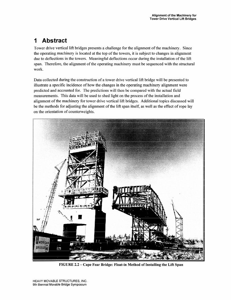
1 Abstract Tower drive vertical lift bridges presents a challenge for the alignment of the machinery. Since the operating machinery is located at the top of the towers, it is subject to changes in alignment due to deflections in the towers. Meaningful deflections occur during the installation of the lift span. Therefore, the alignment of the operating machinery must be sequenced with the structural work.
Data collected during the construction of a tower drive vertical lift bridge will be presented to illustrate a specific incidence of how the changes in the operating machinery alignment were predicted and accounted for. The predictions will then be compared with the actual field measurements. This data will be used to shed light on the process of the installation and alignment of the machinery for tower drive vertical lift bridges. Additional topics discussed will be the methods for adjusting the alignment of the lift span itself, as well as the effect of rope lay on the orientation of counterweights.
FIGURE 2.2 - Cape Fear Bridge: Float-in Method of Installing the Lift Span
HEAVY MOVABLE STRUCTURES, INC. 9th Biennial Movable Bridge Symposium
Alignment of the Machinery for Tower Drive Vertical Lift Bridges
2 Introduction This paper will limit its discussion to tower drive vertical lift bridges. The author served as a mechanical inspector during the construction of a combined highway/freight tower drive vertical lift bridge. Data collected during the construction of this bridge will be presented. Due to ongoing bonding issues, the bridge will remain anonymous.
There are three preferred types of movable bridge: bascule, swing, and vertical lift. The first major vertical lift bridge in the U.S. was the South Halstead Street bridge in Chicago, designed by Waddell in 1892. Today, there are three main types of vertical lift bridges: span drive, tower drive, and tower-span drive. The tower-span drive type is particularly well suited for short spans that require only a limited clearance, as is often the case for crossings over minor canals. Both the span drive and tower drive types are well suited to long spans when a finite vertical clearance is acceptable. This is often the case when the clearance is limited elsewhere on the same waterway by a high level fixed bridge.
The tower drive type requires two independent sets of operating machinery, whereas the span drive type requires only a single operating machinery unit. For this reason tower drive types tend to be more expensive that the span drive type to construct, operate, and maintain. However, as the operating machinery for tower drive bridge is discretely housed within the towers, it is generally considered to be more architecturally acceptable. For these reasons, the tower drive type is often preferred for highway bridges and the span drive type for railroad bridges.
3 Explanation of Alignment "Aligning the machinery" is the process of orientating the mechanical components with respect to one another. AASHTO 1988 M4.1.2 states, "The installation and adjustment of machinery shall be by competent millwrights experienced in this class of work." Since perfect alignment is an unobtainable goal, even for the most skilled and experienced millwrights, the quality of the machinery's alignment is determined by measuring the misalignment. AASHTO and AREMA leave it up to the designer to specify the exact range of acceptable misalignment for each component of the mechanical system. The typical symptoms of excessive misalignment of any component include excessive noise, heat generation, and premature wear. There are three main components where misalignment should be measured and minimized: couplings, gears, and the lift span as a whole. There are other components that require alignment, such as bearings and brakes; these components vary according to type. Therefore, information on the alignment of these components should be obtained from the manufacturer.
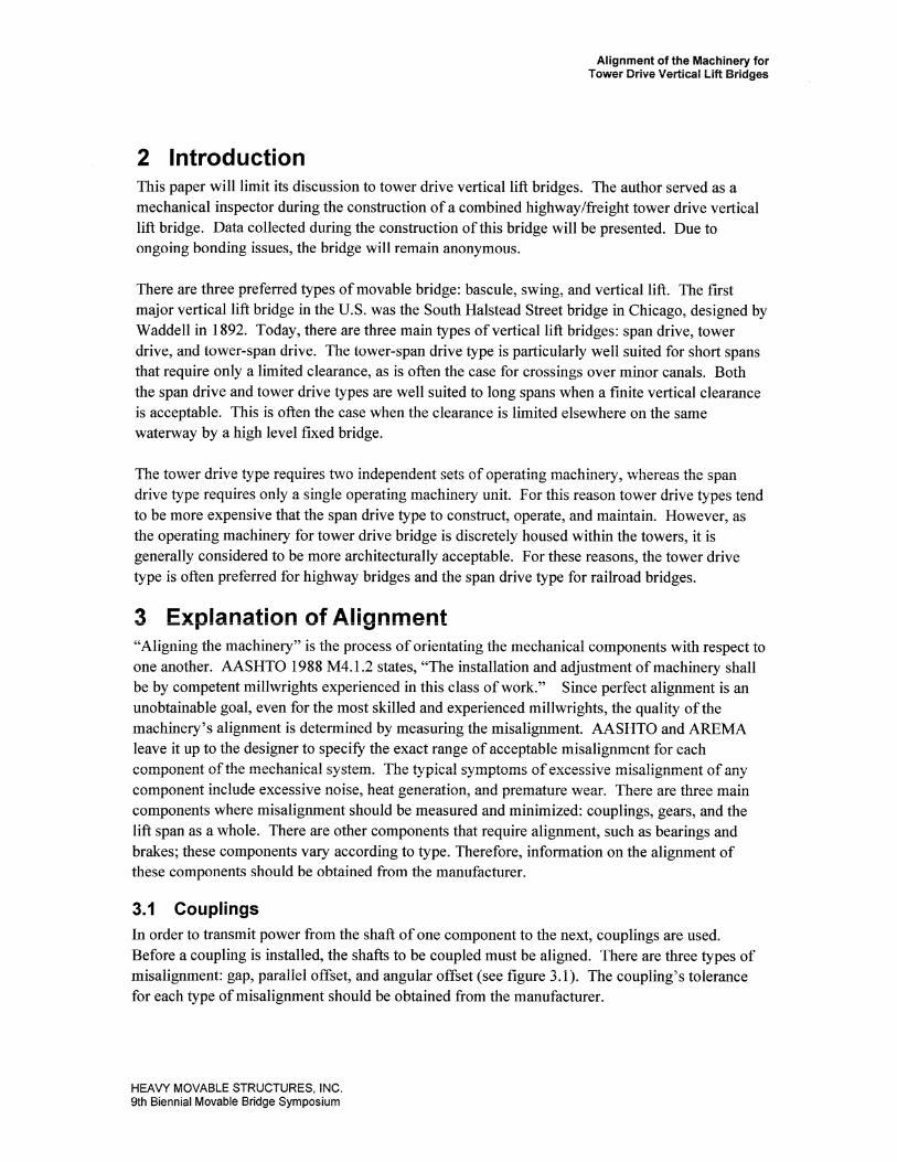
3.1 Couplings In order to transmit power from the shaft of one component to the next, couplings are used. Before a coupling is installed, the shafts to be coupled must be aligned. There are three types of misalignment: gap, parallel offset, and angular offset (see figure 3.1). The coupling's tolerance for each type of misalignment should be obtained from the manufacturer.
HEAVY MOVABLE STRUCTURES, INC 9th Biennial Movable Bridge Symposium
Alignment of the Machinery for Tower Drive Vertical Lift Bridges
ANGULAR MISALIGNMENT PAMLLEt OFFSET MISALIGNMENT
4 LY
FIGURE 3.1 -Misalignments of Couplings (ref. 4)
3.2 Gears The alignment of a gear set is determined by measuring backlash and crossmesh. Backlash is a function of the distance between the gear's pitch circles. In determining backlash, a feeler gauge is used to measure the gap between gear teeth that are meshed. Crossmesh is a function of the parallelism of the shafts. The cross mesh is the difference between the backlash readings at either side along a tooth. The tolerances for backlash and crsssmesh are expressed as a distance, in millimeters or thousandths of an inch. Another measurement of misalignment is contact area, which is expressed as a percentage. However, if backlash and crossmesh are within tolerance, than contact the area is usually not an issue. Tolerances for the alignment of gears should be obtained from AGMA.
3.3 Lift Span The most crucial component, with regards to alignment, is the lift span itself. Two types of lift span misalignment are of concern: skew and warp.
3.3.1 Skew
Since tower drive vertical bridges have independent mechanical systems in each tower, it is crucial that these systems be synchronized. A lack of synchronization will result in skew. Skew is the rotation of the bridge about its transverse axis. If the span skews too far it is libel to lock between the towers, risking considerable damage. The control of skew is done with the electrical systems and is therefore beyond the scope of this paper.
3.3.2 Warp (Transverse Imbalance)
Warp is the rotation of the span about its longitudinal axis. The primary cause of warp is a transverse imbalance between the span and counterweights. Generally, a "warp adjustment" clutch or coupling is provided. However, this is a misnomer. The warp adjustment clutch/coupling does not have the ability to make lasting adjustments to the warp of the span. This phenomenon was exhibited during the construction of the aforementioned bridge. It was noted that one of the live load shoes was not seating when the bridge was closed. Adjusting the warp adjustment coupling cleared up the problem for a few openings. It was determined that a transverse imbalance betwccn thc span and countcrwcight was causing the ropes to slip over the shcave, ever so slightly, until the said shoe would no longer seat. The solution was to rectify the
HEAVY MOVABLE STRUCTURES, INC 9th Biennial Movable Bridge Symposium
Alignment of the Machinery for Tower Drive Vertical Lift Bridges
transverse balance by shifting blocks in the counterweight followed by the re-adjustment of the warp adjustment coupling. The knction of the warp adjustment coupling is to provide an adjustment to equalize the driving torque transmitted to all the sheaves. Methods for determining the presence of and eliminating warp will be discussed in section 6.2 of this paper.
4 Load Induced Alignment Problems There are two different methods used for the construction of the lift span. The first method, called float-in, is to construct the lift span on barges and install it by floating it into place. The second method is to construct it in the raised position. This discussion will be limited to the complications particular to the float in method of construction.
AASHTO 1988 M4.1.2 states: "The final alignment and adjustment of machinery parts, whose relative position is affected by deflection or movement of the supports under full dead load . . . shall not be made until such deflection or movement has taken place." Since the operating machinery is located at the top of the towers, it is subjected to changes of alignment due to load- induced deflections of the towers. The float-in method causes a dilemma with regards to machinery alignment due to the following set of conditions. It is desirable to make the operating machinery functional prior to floating in the lift span because it is necessary to lift the span out of the way of marine traffic as soon as possible. Therefore the operating machinery is generally installed prior to the installation of the lift span. The installation of the lift span applies new loads to the tower that were not present during alignment. These loads can cause noticeable deflections that change the operating machinery's alignment.
It is possible to calculate the expected deflections and align the machinery accordingly. However, it must be recognized that despite these efforts the alignment of all components must be checked after the span is floated in and installed. Any components with misalignments greater than specified must be re-aligned.
5 Machinery Alignment Sequence of the Anonymous Bridge
The contractor installed and aligned the operating machinery prior to the float in of the lift span. The fundamental rule of machinery alignment is to start at the outside and work your way in. For tower drive vertical lift bridges this means that the sheaves are positioned first and all other mechanical components are aligned to them, finishing with the prime mover. The machinery was installed and aligned on the East tower first. After its completion, it was recognized that there was a potential for the alignment to change upon the installation of the lift span, due to tower dcflcctions. The contractor's engineers performed a finite clcmcnt analysis to predict these tower deflections. The machinery on the West tower was aligned according to these predictions.
The two main locations where tower deflections affected machinery alignment was the backlash between the ring gears and pinions, and at the pinion couplings. Prior to the installation of the lift span it was only practical to measure the backlash in the 0 feet-of-lift position, since the ropes were already draped over the sheaves. Table 5.1 shows the backlash before and after the installation of the lift span. The changes in backlash were significant and were not as the calculations predicted. Re-alignment was required. 'l'he backlash was adjusted with a
HEAVY MOVABLE STRUCTURES, INC. 9th Biennial Movable Bridge Symposium
Alignment of the Machinery for Tower Drive Vertical Lift Bridges
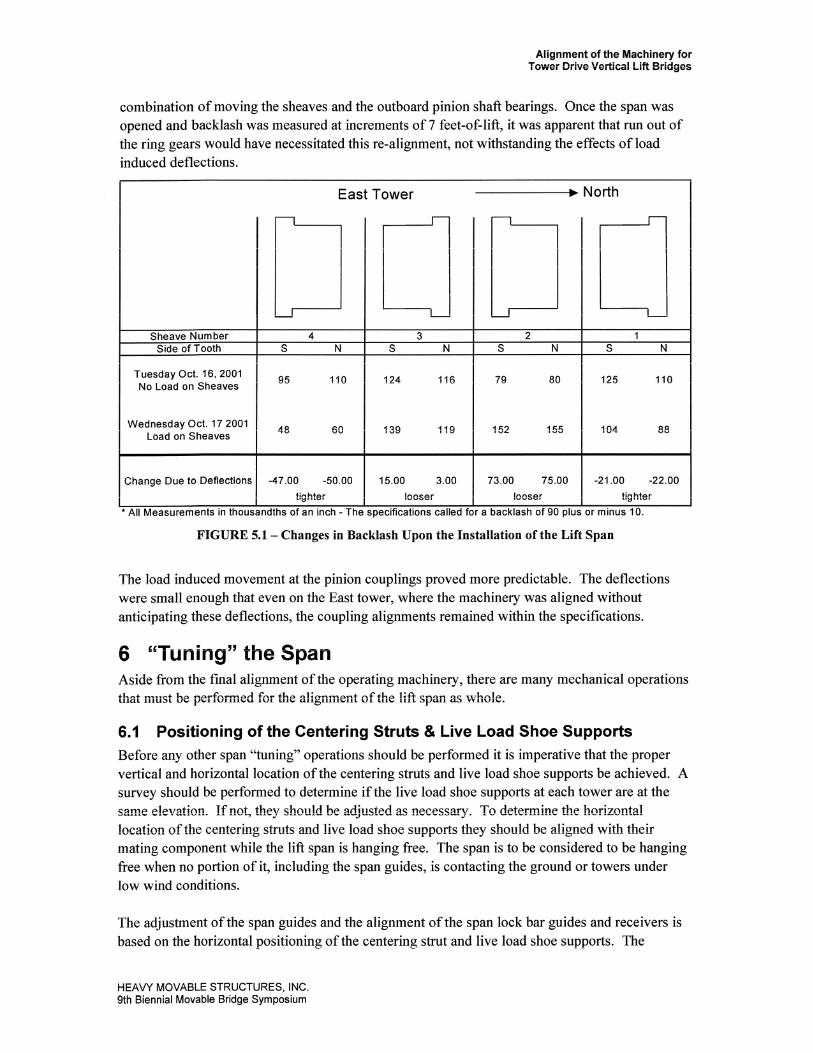
combination of moving the sheaves and the outboard pinion shaft bearings. Once the span was opened and backlash was measured at increments of 7 feet-of-lift, it was apparent that run out of the ring gears would have necessitated this re-alignment, not withstanding the effects of load induced deflections.
r East Tower - North I
Tuesday Oct. 16,2001 95 No Load on Sheaves
116
I Change Due to Deflections 1 -47.00 -50.00 1 15.00 3.00
Wednesday Oct. 17 2001 Load on Sheaves
tighter I looser 'All Measurements in thousandths of an inch -The specifications called
48 60 1 I 3 9 119
r a backlash of 90 plus or minus 10.
FIGURE 5.1 - Changes in Backlash Upon the Installation of the Lift Span
The load induced movement at the pinion couplings proved more predictable. The deflections were small enough that even on the East tower, where the machinery was aligned without anticipating these deflections, the coupling alignments remained within the specifications.
6 "Tuning" the Span Aside from the final alignment of the operating machinery, there are many mechanical operations that must be performed for the alignment of the lift span as whole.
6.1 Positioning of the Centering Struts & Live Load Shoe Supports Before any other span "tuning" operations should be performed it is imperative that the proper vertical and horizontal location of the centering struts and live load shoe supports be achieved. A survey should be performed to determine if the live load shoe supports at each tower are at the same elevation. If not, they should be adjusted as necessary. To determine the horizontal location of the centering struts and live load shoe supports they should be aligned with their mating component while the lift span is hanging free. The span is to be considered to be hanging free when no portion of it, including the span guides, is contacting the ground or towers under low wind conditions.
The adjustment of the span guides and the alignment of the span lock bar guides and receivers is based on the horizontal positioning of the centering strut and live load shoe supports. The
H E A W MOVABLE STRUCTURES, INC 9th Biennial Movable Bridge Symposium
Alignment of the Machinery for Tower Drive Vertical Lift Bridges
adjustment of the warp coupling and the transverse balance of the span and counterweights are effected by the relative vertical positioning of the live load shoe supports. The positioning of the deck's finger joints is also dependent on the location of the live load shoes. As any error in the location of the live load shoe supports or centering strut will be carried over to all of these components, it is prudent to double check their location before moving on.
6.2 Adjustment of the Warp As discussed in section 3.3.2, warp is the rotation of the span about its longitudinal axis and is caused by a transverse imbalance between the span and counterweights. Warp will manifest itself with one or both of the following indicators:
1 .) One of the live load shoes will not seat upon closing the span.
2.) The contact area is at the top of the pinion teeth on one side of the tower and at the bottom of the teeth on the other side of the tower.
The warp is correct when the pinion shafts equally share the torque of driving the bridge and the live load shoes equally share the unbalance load, when the bridge is seated. Three conditions must be present to approach this goal:
1 .) The live load shoe supports must be at the same relative elevation
2.) The span and counterweight must be transversely balanced.
3.) The warp adjustment clutch/coupling must be properly adjusted. If the span exhibits one of the indications of warp, than at least one of the above conditions is not being met.
7 The Effect of Rope Lay on Counterweight Orientation It is interesting to note that it is customary on vertical lift bridges to use all right hand lay ropes with the main counterweight (ref. AASHTO M2000 6.8.3.3.3). However, with the auxiliary counterweight ropes it is necessary to specify half of the ropes as left hand lay.
As a wire rope is loadcd, it tends to unravel. Since the ropes are rigidly attached to the counterweight, and not allowed to unravel, this tendency results in a torque that is applied by each rope to the counterweight. The direction of the torque is oppositc for right hand and left hand lay ropes. For the 6 x 25 fiber core ropes that are generally used on movable bridges, the magnitude of the torque is equal to an empirical factor of 0.09 multiplied by the load and diameter of the rope (ref. Wire Rope Corporation of America).
Experience has shown that this torque has an inconsequential effect on the main counterweight. However, auxiliary counterweights have been proven to forcibly ride against the guide rails if half the ropes are not left hand lay. The author set out to calculate the angle off-true that each of the counterweights would hang if supported solely by right hand lay ropes. The results were that the main counterweight hangs at an angle of 0.02" versus >90° for the auxiliary counterweight (see the Appendix for the analysis). The auxiliary counterweight would not actually be allowed to rotate more than a few degrees, since it is constrained by guides. The calculations indicate that in constraining this rotation the guides would exert a 57 lb force on each side of the auxiliary
HEAVY MOVABLE STRUCTURES, INC. 9th Biennial Movable Bridge Symposium
Alignment of the Machinery for Tower Drive Vertical Lift Bridges
counterweight. The reason that the auxiliary counterweight is susceptible to load induced rotation is due to the short horizontal distance between its center of gravity and the rope attachments.
8 Conclusion As shown on the aforementioned bridge, the installation of the lift span can cause significant enough changes in machinery alignment that some components may require re-alignment. Calculating the expected deflections and aligning the machinery accordingly can minimize the extent of the required re-alignments, but will not necessarily eliminate them.
9 References 1 .)American Association of State Highway and Transportation Officials (AASHTO), Movable Highway Bridge Design Specifications, 2000
2.)AASHTO, Standard Specifications for Movable Highway Bridges, 1988
3.)United States Department of Transportation Federal Highway Administration, Bridge Inspectors Manual for Movable Bridges, 1977
4.)The Falk Corporation, Installation and Maintenance Guide for Steelflex Couplings 428-210
10 Appendix - Analysis of Counterweight Rotation Due to Load Induced Torque in Wire Ropes
Purpose: To find the angle of rotation (a) for counterweights hanging from wire ropes of the same hand lay.
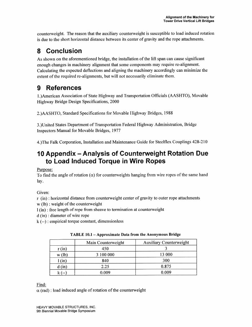
Given: r (in) : horizontal distance from counterweight center of gravity to outer rope attachments w (lb) : weight of the counterweight 1 (in) : free length of rope from sheave to termination at counterweight d (in) : diameter of wire rope k (--) : empirical torque constant, dimensionless
TABLE 10.1 - Approximate Data from the Anonymous Bridge
Find: a (rad) : load induced angle of rotation of the counterweight
HEAVY MOVABLE STRUCTURES, INC. 9th Biennial Movable Bridge Symposium
Auxiliary Counterweight 3
13 000 3 00
0.875 0.009
r (in) w (lb) I (in) d (in) k (--I
Main Counterweight 450
3 100 000 840 2.25 0.009
Alignment of the Machinery for Tower Drive Vertical Lift Bridges
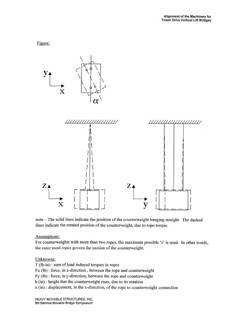
Figure:
note - The solid lines indicate the position of the counterweight hanging straight. The dashed lines indicate the rotated position of the counterweight, due to rope torque.
Assumptions: For counterweights with more than two ropes, the maximum possible 'r' is used. In other words, the outer most ropes govern the motion of the counterweight.
Unknowns: T (lb-in) : sum of load induced torques in ropes Fx (lb) : force, in x-direction , between the rope and counterweight Fy (Ib) : force, in y-direction, between the rope and counterweight h (in) : height that the counterweight rises, due to its rotation x (in) : displacement, in the x-direction, of the rope to counterweight connection
HEAW MOVABLE STRUCTURES, INC 9th Biennial Movable Bridge Symposium
Alignment of the Machinery for Tower Drive Vertical Lift Bridges
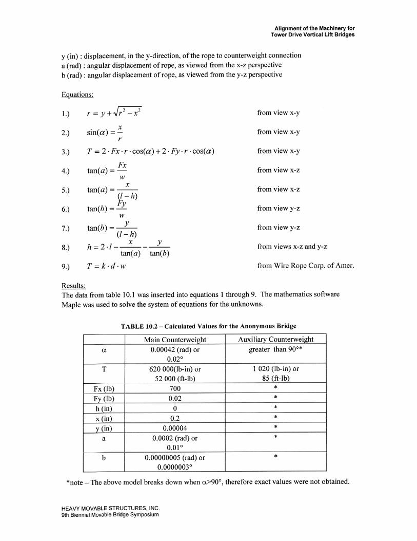
y (in) : displacement, in the y-direction, of the rope to counterweight connection a (rad) : angular displacement of rope, as viewed from the x-z perspective b (rad) : angular displacement of rope, as viewed from the y-z perspective
Equations:
1.) r = y+.\lr2 - x 2 from view x-y
X 2.) sin(a) = - from view x-y
r
3.) T=2.Fx.r.cos(a)+2-Fy.r.cos(a) from view x-y
from view x-z
from view x-z
from view y-z
from view y-z
from views x-z and y-z
from Wire Rope Corp. of Amer.
Results: The data from table 10.1 was inserted into equations 1 through 9. The mathematics software Maple was used to solve the system of equations for the unknowns.
TABLE 10.2 - Calculated Values for the Anonymous Bridge
*note - The above model breaks down when a>90°, therefore exact values were not obtained.
HEAVY MOVABLE STRUCTURES, INC 9th Biennial Movable Bridge Symposium