ESOMAR YRA-2011 Preriit K Souda Six people Six lives One hope

Alignment of S-LSR
H. Souda, M. Tanabe, T. Ishikawa, M. Ikegami, T. Takeuchi*, H. Tongu, T. Shirai, A. Noda
ICR, Kyoto University*Accelerator Engineering Corporation

12 Feb 2008 / The 10th International Workshop on Accelerator Alignment 1
Alignment of S-LSR
Contents
1. Introduction of S-LSRPurpose and specification of the ringDecision of alignment tolerance
2. AlignmentMagnet ShufflingAlignment with a laser trackerMagnet pole length measurement by a laser tracker
3. Effect on Beam OpticsBeta function and stopbandCOD and COD Correction

12 Feb 2008 / The 10th International Workshop on Accelerator Alignment 2
Alignment of S-LSR
S-LSR at Kyoto University
S-LSR: Small Laser equipped Storage RingConstructed at Kyoto University(Uji
campus)
Collaboration with NIRS(National Institute of Radiological Sciences)
Advanced Compact Accelerator Development project(JFY2001-2005)
ICC KyotoICC KyotoVenue of 1Venue of 1stst
IPACIPAC
Kyoto UniversityKyoto UniversityUjiUji
CampusCampus10km
ShinkansenShinkansenKyoto StationKyoto Station
KatsuraKatsura
CampusCampus
Yoshida(Main)Yoshida(Main)CampusCampus KEK
Tokyo
Kyoto

12 Feb 2008 / The 10th International Workshop on Accelerator Alignment 3
Alignment of S-LSR
Beam Cooling and Alignment
Main purpose = Beam CoolingElectron Cooling
of 7 MeV
proton
Medical Application, Beam orderingLaser Cooling
of 40keV 24Mg+
Low temperature limit, Crystalline Beam
・To get strong cooling force…Ion beam orbit
must overlap electron/laser path
・Toward 3-dimensional Beam Crystallization…High periodicity(COD, Beta function) is necessary.
COD and beta function is important in alignment.

12 Feb 2008 / The 10th International Workshop on Accelerator Alignment 4
Alignment of S-LSR
Overview of S-LSR
Injection Line
Beam Transport
Heavy Ion SourceProton Linac(1988-)
Storage Ring
Circumference:22.557mDiameter: 7.744mNumber of BM: 6Number of QM: 12(2 series)

12 Feb 2008 / The 10th International Workshop on Accelerator Alignment 5
Alignment of S-LSR
Alignment toleranceCOD from Misalignment vs. Magnet field error
Bending Magnets Quadrupole MagnetsError Source Error Amount COD (mm) Error Source Error Amount COD (mm)
BL Product Δ(BL/BL)=1x10-4
0.33(Horizontal) GL Product Δ(GL/GL)=
1x10⁻³ 0.
X Position Dx
=0.1 mm 0.24 (H) X Position Dx
=0.1 mm 0.11 (H)
Y Position Dy
=0.1 mm 0.02 (V) Y Position Dy
=0.1 mm 0.11 (V)
S Position Ds
=0.1 mm 0.15 (H) S Position Ds
=0.1 mm 0.
X Rotation Dφ
=0.05 mrad 0.06 (V) X Rotation Dφ
=0.05 mrad 0.01 (V)
Y Rotation Dθ
=0.1 mrad 0.15 (H) Y Rotation Dθ
=0.1 mrad 0.02 (H)
S Rotation Dψ
=0.05 mrad 0.10 (V) S Rotation Dψ
=0.05 mrad 0.
Alignment ToleranceDisplacement: 0.1mmRotation:0.1mrad(BM) 1mrad(QM)
x
s
y
θψ
φ
12 Feb 2008 / The 10th International Workshop on Accelerator Alignment 6
Alignment of S-LSR
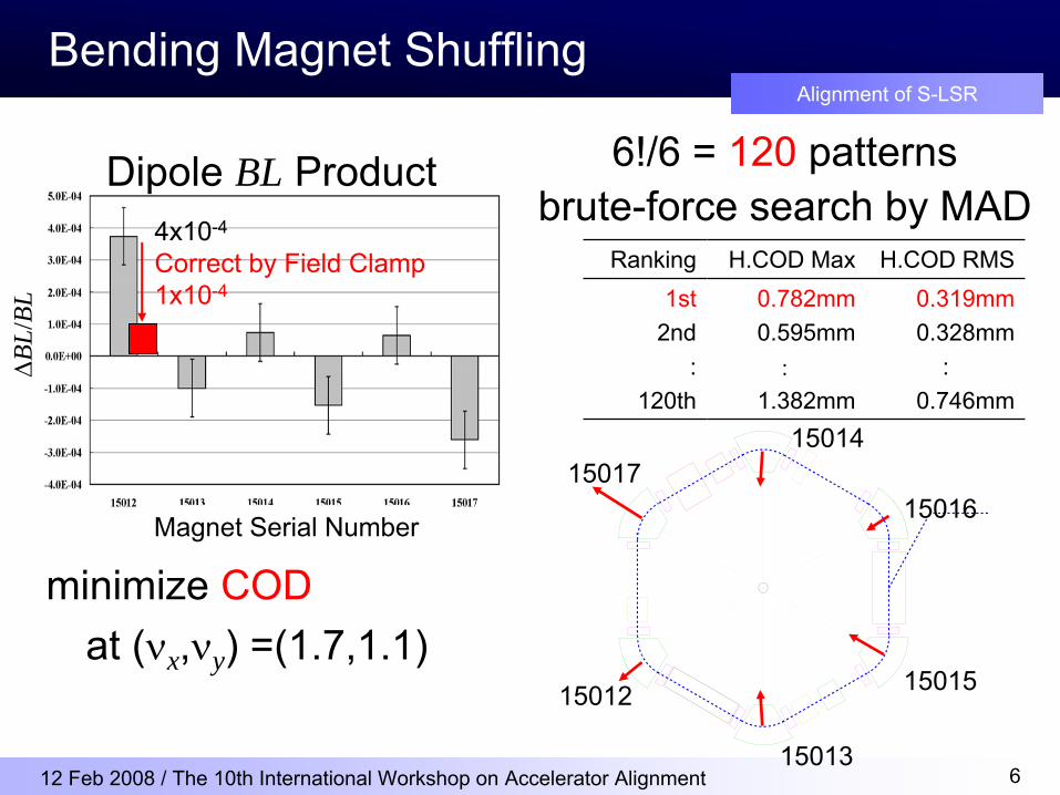
Bending Magnet Shuffling
minimize CODat (νx ,νy ) =(1.7,1.1)
Dipole BL Product
ΔBL
/BL
4x10⁻⁴
Correct by Field Clamp1x10-4
Magnet Serial Number
6!/6 = 120
patternsbrute-force search by MAD
Ranking H.COD Max H.COD RMS1st
2nd:
120th
0.782mm0.595mm
:1.382mm
0.319mm0.328mm
:0.746mm
15015
15013
15012
1501715014
15016

12 Feb 2008 / The 10th International Workshop on Accelerator Alignment 7
Alignment of S-LSR
Quadrupole Magnet Shuffling
Quadrupole GL Product
1-6Upstream Q
7-12Downstream Q
ΔG
L/G
L
Magnet Serial Numberminimize Beta function error~minimize Betatron
stopband
6!x6! = 518400
patterns brute-force search by MAD
Ranking (δνx , δνy )[x10-4]1st
2nd:
518400
(8.00, 6.19)(7.47, 6.87)
:(5.57, 22.26)
Q12
Q5Q11Q2
Q9
Q1
Q10
Q4Q8 Q6
Q7
Q3

12 Feb 2008 / The 10th International Workshop on Accelerator Alignment 8
Alignment of S-LSR
Alignment using Laser Tracker
Laser Tracker: SMX Tracker4500
Total Station: Leica TDA5005
Resolution ~50μm
20 Dec 2004 ~ 24 Dec 200425 Jan 2005 ~ 26 Jan 2005
Alignment chief: T. Shirai(ICR, Kyoto Univ.)Measurement: K. Mishima(PASCO)
Fiducial
Hole(BM:3QM:2)
+y:North
+x:East +z:Up

12 Feb 2008 / The 10th International Workshop on Accelerator Alignment 9
Alignment of S-LSR
Result of Alignment
+/-50μm +/-50μm
All displacements are less than 0.1mm65% are less than 0.05mm
BM displacement QM displacement

12 Feb 2008 / The 10th International Workshop on Accelerator Alignment 10
Alignment of S-LSR
Measurement of magnet pole length
Knife-edgecontact type probeAccuracy ~0.2mm
Reference planeof Rogowski
cut
Measure 3 pointsto determine the line
BM
Probe
Actual pole length (base line of effective length)is measured by laser tracker.

12 Feb 2008 / The 10th International Workshop on Accelerator Alignment 11
Alignment of S-LSR
Measured magnet pole length
Serial No. Location Error
15012 BM3Upstream
0.0
mmDownstream
-0.4
mm
15013 BM4-0.1 mm-0.1 mm
15014 BM50.0 mm
-0.1 mm
15015 BM1-0.1
mm-0.2 mm
15016 BM60.0 mm0.2 mm
15017 BM20.1 mm
-0.1 mm
Overestimate!
Return the Field Clamp
Actual
Actual + Field Clamp Moved
COD:
Max 0.8mm 1.0mmRMS 0.3mm 0.4mm
(5th of 120)

12 Feb 2008 / The 10th International Workshop on Accelerator Alignment 12
Alignment of S-LSR
Effect to the Beam Optics
Dx[mm] Dy[mm] Ds[mm] Dφ[mrad] Dθ[mrad] Dϕ[mrad]BM1 -0.017 0.003 0.049 -0.037 -0.027 0.020BM2 -0.010 0.027 -0.013 -0.007 -0.104 0.007BM3 0.053 0.040 0.009 0.000 -0.032 -0.040BM4 -0.029 0.043 0.008 -0.013 0.006 -0.010BM5 0.031 -0.090 0.039 -0.037 -0.004 -0.013BM6 0.048 -0.027 -0.004 -0.040 -0.018 -0.007
QM11 0.002 0.050 -0.026 -0.020 -0.169 -0.010QM12 0.048 -0.030 0.012 0.030 0.174 -0.020QM21 -0.050 -0.040 -0.032 0.010 -0.076 -0.010QM22 0.003 0.080 -0.030 0.070 -0.130 -0.010QM31 0.027 0.060 0.020 -0.020 -0.725 0.000QM32 -0.019 -0.010 0.029 0.000 0.077 -0.050QM41 0.046 0.000 -0.042 -0.030 0.277 -0.050QM42 0.003 0.050 0.071 -0.030 -0.421 -0.020QM51 -0.058 -0.070 0.084 -0.070 0.163 0.030QM52 -0.032 -0.070 -0.079 -0.030 0.270 0.040QM61 -0.017 -0.050 0.019 0.050 0.205 -0.040QM62 -0.052 -0.070 -0.030 0.050 0.108 0.010
x
s
y
θψ
φ
Translation
RectangularCoordinate
toFrenet-SerretCoordinate

12 Feb 2008 / The 10th International Workshop on Accelerator Alignment 13
Alignment of S-LSR
Beta Function
Position βx (meas) βx (MAD)QM11 2.137 2.252QM21 2.184 2.256QM22 2.149 2.253QM32 2.089 2.254QM41 2.164 2.255QM51 2.164 2.254QM61 2.179 2.253
Beta function measurementChange QM correction currentMeasure betatron
tune shift
Stopband
MeasurementChange QM main currentMeasure beam life(>10sec)around ν=1.5
δνx =1.1x10⁻³ (calc 0.8x10⁻³)Δβx /βx < 2x10⁻³
δνy =1.2x10⁻³ (calc 0.6x10⁻³)Δβy /βy < 6x10⁻³
Δβx /βx = 0.06(2σ)

12 Feb 2008 / The 10th International Workshop on Accelerator Alignment 14
Alignment of S-LSR
COD Measurement & Correction
BM1
BM2
BM3
BM4
BM5
BM6
ECDCCT
RFKO
ESKICK
CAVINDAC
CCD
PMT
Laser
ESBPMH.Corrector
V.CorrectorAperture
MCP
6 Electrostatic BPMs(Triangle
Plate)6 Horizontal Correctors(BM Correction Current)6 Vertical Correctors(BPM as Electrostatic Kicker)
φ =10mm
φ =6mm
φ =3mm
φ =2mm Laser Section~1m
Alignment Target forion beam and LaserCross angle <0.2mrad
-
AB
C
D
Beam
Center
+
Position
- ---
--
-
-
MirrorCharge

12 Feb 2008 / The 10th International Workshop on Accelerator Alignment 15
Alignment of S-LSR
COD correction result
Horizontal COD Vertical COD
Max 2.9mm 0.38mm(calc 1.0mm)
RMS 0.85mm 0.27mm(calc 0.4mm)
Max 3.7mm 0.39mm(calc 0.7mm)
RMS 2.1mm 0.33mm(calc 0.4mm)
40keV 24Mg+ beam, ν = (1.644,1.197)
12 Feb 2008 / The 10th International Workshop on Accelerator Alignment 16
Alignment of S-LSR
Summary
•
Bending and quadrupole magnets of S-LSR was aligned using a laser tracker.
•
Magnets are shuffled to minimize COD
and betatron
stopband.
•
All magnets were aligned with displacements of less than 0.1mm, 65% are less than 0.05mm.
•
Measured COD is the same order of calculation by alignment error, and corrected to +/-0.4mm.


![Les apôtres dans la Souda - COnnecting REpositories12 Souda, π2968 (in A. ADLER [éd.], Suidae Lexicon, IV, Lipsiae 1935 [Lexicographi Graeci, 1], p. 248 ll. 12-17). Voir 1 Co 12,](https://static.fdocuments.us/doc/165x107/5fe42f86a5d52f51813e1baf/les-aptres-dans-la-souda-connecting-repositories-12-souda-2968-in-a-adler.jpg)