ALiEn Plunger Lift Controller - Extreme Telematics...
56
ALiEn Plunger Lift Controller Installation and Operations Manual Software Revision 6.5.3 8/12/2010
Transcript of ALiEn Plunger Lift Controller - Extreme Telematics...

ALiEn Plunger Lift Controller Installation and Operations Manual
Software Revision 6.5.3
8/12/2010

Extreme Telematics Corp. CONFIDENTIAL and PROPRIETARY
NOTICE OF CONFIDENTIALITY AND NONDISCLOSURE
This document contains information that is protected as an unpublished work by Extreme Telematics Corporation under applicable copyright laws. Recipient is to retain this document in confidence and is not permitted to copy, reproduce, or to incorporate the contents hereof into any other media other than as permitted in a written agreement with Extreme Telematics Corporation. The below statutory copyright notice shall not imply or be deemed publication of this product.
Modbus is a trademark of Modicon, Inc.
Copyright © 2010 Extreme Telematics Corporation. All Rights Reserved.

Extreme Telematics Corp. CONFIDENTIAL and PROPRIETARY
Revision History
Revision Date Author Changes
6.x.x 21/04/2008 Mark Scantlebury Initial Version
6.5.0 15/01/2009 Mike Hughesman Additions for Close Time Optimization
6.5.3 01/12/2010 Mark Scantlebury Corrections to Timer Optimization and screen additions.

ALiEn Plunger Lift Controller Installation and Operations Manual Revision 6.5.3 8/12/2010
- i -
Extreme Telematics Corp. CONFIDENTIAL and PROPRIETARY
Acronyms
ADC Analog-to-Digital Converter
AI Analog Input
ALiEn Artificial Lift Enhancement
CVC Configurable Valve Controller
DAC Digital-to-Analog Converter
DI Digital Input
DO Digital Output
ESD Emergency Shut Down
N/C Normally Closed
N/O Normally Open
PSI Pounds per Square Inch
R Read Permission
RTU Remote Terminal Unit
R/W Read/Write Permission
SCADA Supervisory Control And Data Acquisition
V Volts
VFD Vacuum Fluorescent Display
VI Virtual Input

ALiEn Plunger Lift Controller Installation and Operations Manual Revision 6.5.3 8/12/2010
- ii -
Extreme Telematics Corp. CONFIDENTIAL and PROPRIETARY
Table of Contents
1 Introduction............................................................................................................................... 1
1.1 Purpose............................................................................................................................. 1
1.2 Overview ........................................................................................................................... 1
1.3 Assumptions...................................................................................................................... 1
2 Controller Overview.................................................................................................................. 1
2.1 Startup............................................................................................................................... 1
2.2 Battery Monitor.................................................................................................................. 1
3 User Interface........................................................................................................................... 2
3.1 Display............................................................................................................................... 2
3.1.1 Menu Area ............................................................................................................. 2
3.1.2 Status Area............................................................................................................ 2
3.1.3 Automatic Shut Off ................................................................................................ 2
3.2 Keypad .............................................................................................................................. 2
3.2.1 Navigation Keys..................................................................................................... 2
3.2.1.1 Select ................................................................................................................ 3
3.2.1.2 Cancel ............................................................................................................... 3
3.2.1.3 Arrow Keys........................................................................................................ 3
3.2.2 Hot Keys ................................................................................................................ 3
3.2.2.1 Close ................................................................................................................. 3
3.2.2.2 Open.................................................................................................................. 3
3.2.2.3 Timer Settings ................................................................................................... 3
3.2.2.4 Cycle Log .......................................................................................................... 6
3.2.2.5 History ............................................................................................................... 7
3.3 Top Level Menu ................................................................................................................ 7
3.3.1 Current State ......................................................................................................... 8
3.3.2 Cycle Information................................................................................................... 8
3.3.3 Current Date/Time ................................................................................................. 8
3.3.4 Change State......................................................................................................... 8
3.4 Setup Menu....................................................................................................................... 8
3.4.1 Date/Time .............................................................................................................. 8
3.4.2 System................................................................................................................... 9
3.4.3 Security................................................................................................................ 10
3.4.4 Inputs ................................................................................................................... 10
3.4.5 Outputs ................................................................................................................ 12
3.4.6 Calibrate .............................................................................................................. 13
3.4.7 Alarms.................................................................................................................. 14

ALiEn Plunger Lift Controller Installation and Operations Manual Revision 6.5.3 8/12/2010
- iii -
Extreme Telematics Corp. CONFIDENTIAL and PROPRIETARY
3.4.8 Optimize............................................................................................................... 15
3.4.9 Modbus................................................................................................................ 17
4 Controller ................................................................................................................................ 18
4.1 Controller Configurations ................................................................................................ 18
4.1.1 Intermitting........................................................................................................... 18
4.1.2 Arrival Sensor Operation ..................................................................................... 19
4.1.2.1 Non-Arrival ...................................................................................................... 20
4.1.2.2 Fast-Trip .......................................................................................................... 21
4.1.3 Line Pressure ...................................................................................................... 21
4.1.4 Pressure Optimization ......................................................................................... 22
4.1.4.1 Casing Pressure.............................................................................................. 25
4.1.4.1.1 Close........................................................................................................... 25
4.1.4.1.2 Afterflow/ Extended Afterflow...................................................................... 26
4.1.4.1.2.1 Low Rise ................................................................................................ 26
4.1.4.1.2.2 Absolute ................................................................................................. 27
4.1.4.1.2.3 Rate Drop............................................................................................... 27
4.1.4.2 Casing Line Differential Pressure.................................................................... 28
4.1.4.3 Flow Differential Pressure ............................................................................... 28
4.1.4.4 Flow Rate ........................................................................................................ 29
4.1.4.4.1 Calculated ................................................................................................... 29
4.1.4.4.2 Switch ......................................................................................................... 29
4.1.4.4.3 Virtual.......................................................................................................... 29
4.1.4.4.4 Sensor......................................................................................................... 29
4.1.5 Timer Optimization .............................................................................................. 29
4.1.5.1 Timer Optimization Parameters ...................................................................... 30
4.1.5.1.1 Rise Time (RTime)......................................................................................... 30
4.1.5.1.2 Target Rise Time (TRTime)........................................................................... 30
4.1.5.1.3 Actual Rise Time (ARTime) ........................................................................... 30
4.1.5.1.4 Miss Percentage (M%)................................................................................. 31
4.1.5.1.4.1 Early Arrival............................................................................................ 31
4.1.5.1.4.2 Late Arrival ............................................................................................. 31
4.1.5.1.5 Timer Mode (TM) ........................................................................................ 32
4.1.5.2 Afterflow Time Optimization ............................................................................ 33
4.1.5.2.1 Afterflow Time (AFTime)................................................................................ 33
4.1.5.2.2 Max Open Time (MOTime)............................................................................ 33
4.1.5.2.3 Remaining Flow Time (RFTime).................................................................... 33
4.1.5.2.4 Extended Afterflow Percentage (EAF%)...................................................... 34

ALiEn Plunger Lift Controller Installation and Operations Manual Revision 6.5.3 8/12/2010
- iv -
Extreme Telematics Corp. CONFIDENTIAL and PROPRIETARY
4.1.5.2.5 Extended Afterflow Time (EAFTime) ............................................................. 34
4.1.5.3 Close Time Optimization ................................................................................. 35
4.1.5.3.1 Close Time (CTime)....................................................................................... 35
4.1.5.3.2 Max Close Time (MCTime)............................................................................ 35
4.1.5.3.3 Remaining Close Time (RCTime).................................................................. 35
4.1.5.3.4 Extra Close Percentage (EC%) ................................................................... 36
4.1.5.3.5 Extra Close Time (ECTime)........................................................................... 36
4.1.6 Dual Valve ........................................................................................................... 37
4.1.6.1 Top Valve ........................................................................................................ 37
4.1.6.2 Flow Tee.......................................................................................................... 38
4.1.6.3 Tank Valve ...................................................................................................... 39
4.1.7 Low Battery.......................................................................................................... 39
5 Modbus Communications....................................................................................................... 40
6 Installation .............................................................................................................................. 40
6.1 Physical Connections...................................................................................................... 40
6.2 Connecting Power........................................................................................................... 42
7 Troubleshooting...................................................................................................................... 42
8 Support ................................................................................................................................... 43
8.1 Software Upgrade ........................................................................................................... 43
8.1.1 Prerequisites........................................................................................................ 44
8.1.2 Setup ................................................................................................................... 44
8.1.3 Upgrade Procedure ............................................................................................. 44
8.1.4 Upgrade Errors .................................................................................................... 44
8.2 Replacement Parts and Accessories .............................................................................. 45
8.3 Technical Support ........................................................................................................... 46
8.3.1 Contacting Support.............................................................................................. 46
8.3.1.1 Web................................................................................................................. 46
8.3.1.2 Phone .............................................................................................................. 46
8.3.2 Identifying the Issue............................................................................................. 46
8.3.2.1 Hardware......................................................................................................... 46
8.3.2.2 Firmware ......................................................................................................... 46
8.3.3 Reporting Software Issues .................................................................................. 46
8.3.4 Repair Process .................................................................................................... 47
Index of Tables
Table 1 - Timer Settings Screens.................................................................................................... 4
Table 2 - Cycle Log Screens ........................................................................................................... 6

ALiEn Plunger Lift Controller Installation and Operations Manual Revision 6.5.3 8/12/2010
- v -
Extreme Telematics Corp. CONFIDENTIAL and PROPRIETARY
Table 3 - History Screens ................................................................................................................ 7
Table 4 - Date/Time Screens........................................................................................................... 9
Table 5 - System Screens ............................................................................................................... 9
Table 6 - Security Screens ............................................................................................................ 10
Table 7 - Inputs Screens ............................................................................................................... 10
Table 8 - Outputs Screens............................................................................................................. 13
Table 9 - Calibrate Screens........................................................................................................... 14
Table 10 - Alarms Screens ............................................................................................................ 14
Table 11 - Optimize Screens ......................................................................................................... 15
Table 12 - Modbus Menus............................................................................................................. 18
Table 13 - Pressure Optimization Modes ...................................................................................... 23
Table 14 - Timer Modes ................................................................................................................ 32
Table 15 - Troubleshooting Guide................................................................................................. 42
Table 16 - Available Replacement Parts and Accessories ........................................................... 45
Table of Figures
Figure 1 - Screen Layout ................................................................................................................. 2
Figure 2 - Navigation Keys .............................................................................................................. 3
Figure 3 - Hot Keys.......................................................................................................................... 3
Figure 4 - Main Menu Structure....................................................................................................... 8
Figure 5 - Well Intermitting ............................................................................................................ 19
Figure 6 - Basic Controller States.................................................................................................. 19
Figure 7 - Arrival Sensor Operation............................................................................................... 20
Figure 8 - Controller Operation with Arrival Sensor....................................................................... 20
Figure 9 - Non-Arrival .................................................................................................................... 21
Figure 10 - Fast Trip ...................................................................................................................... 21
Figure 11 - Using Line Pressure.................................................................................................... 22
Figure 12 - Line Pressure Cycle .................................................................................................... 22
Figure 13 - Pressure Based Optimization ..................................................................................... 23
Figure 14 - Extended Afterflow Optimization................................................................................. 25
Figure 15 - Casing Pressure Close Cycle ..................................................................................... 25
Figure 16 - Open Casing Pressure Reset Point ............................................................................ 26
Figure 17 - Afterflow/Extended Afterflow Casing Pressure ........................................................... 26
Figure 18 - Casing Pressure Low Rise Method............................................................................. 27
Figure 19 - Casing Pressure Absolute Method ............................................................................. 27
Figure 20 - Casing Pressure Rate Drop Method........................................................................... 28
Figure 21 - Open Casing Line Differential Trip.............................................................................. 28

ALiEn Plunger Lift Controller Installation and Operations Manual Revision 6.5.3 8/12/2010
- vi -
Extreme Telematics Corp. CONFIDENTIAL and PROPRIETARY
Figure 22 – Target Rise Time........................................................................................................ 30
Figure 23 - Early Arrival................................................................................................................. 31
Figure 24 - Late Arrival .................................................................................................................. 32
Figure 26 – Remaining Flow Time................................................................................................. 33
Figure 25 - EAF% .......................................................................................................................... 34
Figure 28 – Remaining Close Time............................................................................................... 35
Figure 27 - EC% ............................................................................................................................ 36
Figure 29 - Top Valve Well Configuration ..................................................................................... 37
Figure 30 - Top Valve Operation ................................................................................................... 37
Figure 31 - Flow Tee Well Configuration....................................................................................... 38
Figure 32 - Flow Tee Operation..................................................................................................... 38
Figure 33 - Tank Valve Well Configuration.................................................................................... 39
Figure 34 - Alien Wiring Diagram .................................................................................................. 40

ALiEn Plunger Lift Controller Installation and Operations Manual Revision 6.5.3 8/12/2010
Page 1
Extreme Telematics Corp. CONFIDENTIAL and PROPRIETARY
1 Introduction
1.1 Purpose
This manual is intended to provide all of the information required to setup and operate the Alien Plunger Lift Controller. As well, it covers basic troubleshooting techniques and support information.
1.2 Overview
The Alien Plunger Lift Controller is a versatile gas well controller that can be used in a number of different configurations. It can function as a simple intermitter or with a plunger and can optimize a well based on pressures or plunger arrival times. In addition, the controller can be accessed remotely using the provided Modbus compatible RS485 communications port.
1.3 Assumptions
The following assumptions have been made when writing this manual:
The reader has some knowledge of the operation of a gas well.
A controller is available as a reference while reading this manual.
2 Controller Overview
2.1 Startup
On power up, the controller is initialized by performing the following operations:
Set the outputs to a known state
Close all valves
Load all previously saved values
Turn on the display
Set the display to show the current controller state as the latest device status information.
The controller automatically enters the Close state when powering up.
2.2 Battery Monitor
The controller samples the battery every 10 minutes, monitoring the voltage in order to prevent unpredictable valve operation. The battery voltage is reported as one of the following:
Normal: The controller behaves normally. If 6 successive battery samples are below 5.5 Volts, the controller closes all valves and enters the Low state. A low battery alarm condition is recorded, which is reported in the history.
Low: If 6 successive samples are above 6.0 Volts, the controller enters the Normal state. When entering the Normal state, the controller will restart to the Close state for a duration specified by the Close Time parameter.
During power on or reset, and before any valves are opened, the battery voltage is sampled. The Normal or Low state is entered based upon this sample.

ALiEn Plunger Lift Controller Installation and Operations Manual Revision 6.5.3 8/12/2010
Page 2
Extreme Telematics Corp. CONFIDENTIAL and PROPRIETARY
3 User Interface
3.1 Display
A Vacuum Fluorescent Display (VFD) is provided which consists of 2 lines x 16 characters. Each character is a 5x7 dot matrix with a full underline bar. The display is partitioned into 2 areas with an unused column between them for spacing.
Figure 1 - Screen Layout
3.1.1 Menu Area
The content of the Menu Area (2 x 10 characters) shows the current state of the controller on startup. This area will change based on user keypad interaction. The current state information as well as the setup menu is available in this area.
3.1.2 Status Area
The Status Area (2 x 5 characters) constantly rotates through all enabled inputs and outputs. By default, this includes the battery voltage as well as the state of Valve A. As other options are enabled on the controller, additional information becomes available in this same area. For example, Valve B will be displayed if it has been enabled. If pressure devices such as line pressure and casing pressure are enabled, their current value will also be displayed.
3.1.3 Automatic Shut Off
The controller is constantly monitoring the input from the operator. If no keys have been pressed in the last 5 minutes, the controller will turn off the display in order to conserve battery power.
3.2 Keypad
An integrated keypad is included which allows the user to change settings, navigate through statistics, and control the well. The following sections discuss the various keys that are available.
3.2.1 Navigation Keys
The navigation keys are used to move through the menus in the controller and input new settings.

ALiEn Plunger Lift Controller Installation and Operations Manual Revision 6.5.3 8/12/2010
Page 3
Extreme Telematics Corp. CONFIDENTIAL and PROPRIETARY
Figure 2 - Navigation Keys
3.2.1.1 Select
Select is used to enter a sub-menu, select a field to be edited, or save changes made while editing a field.
3.2.1.2 Cancel
Cancel is used to backup through the menu levels or cancel an edit.
3.2.1.3 Arrow Keys
The arrow keys allow the user to move up/down and left/right. If the display is on a line that has a sub menu associated with it, pressing “Right” will enter the sub menu. Conversely, pressing the “Left” arrow will go back one level of menu depth. If a field can be edited the “Right” arrow will put the controller into edit mode. Moving left and right while in edit mode will switch between different fields on the screen. If the user moves past the end of the screen to the left, the edit is cancelled. Move past the end of the screen to the right and the edited value is saved.
3.2.2 Hot Keys
The hot keys are provided to take the user to special menus or provide instant action.
Figure 3 - Hot Keys
3.2.2.1 Close
Pressing Close will send the controller to the close state, closing all valves.
3.2.2.2 Open
Pressing Open will send the controller to the open portion of the cycle. The action that is taken depends on the number of valves configured, how they are set to operate, and if there are any special checks required, such as casing and/or line pressure. The normal mode of operation is to go to Rise, which opens Valve A and waits for a plunger arrival to occur.
3.2.2.3 Timer Settings
The Timer Settings hot key navigates to a special menu that contains all of the times that are used by the controller as well as the set points for pressure devices. The timers control how long the controller leaves the well open, waits for an arrival, or closes the well in. These settings give

ALiEn Plunger Lift Controller Installation and Operations Manual Revision 6.5.3 8/12/2010
Page 4
Extreme Telematics Corp. CONFIDENTIAL and PROPRIETARY
the installer/operator control over how the well behaves. The following is a list of the timers and settings that are available in this menu:
Table 1 - Timer Settings Screens
Screen Description Default Value
Close Time This determines the normal duration of the Close portion of the cycle.
0h45m00s
Non-Arrival Close Time
This determines the duration of the Close portion of the cycle following a non-arrival.
Not used if the Arrival Sensor is disabled.
1h00m00s
Extra Close Time
This timer shows the current amount of Extra Close.
In Close Timer Based Optimization this timer will adjust automatically to help bring the plunger to surface at the time specified by the Target Rise Time.
0h00m00s
Max Close Time
The maximum amount of close time for any one cycle. This is used for Close Time Optimization.
8h00m00s
Rise Time This time is used to indicate that the plunger is not likely to arrive at the surface unless special action is taken. If this time expires before the plunger arrives, the controller will bypass the Afterflow portion of the cycle and close the valves for the Extended Close Time, or possibly shutdown the well. The intent is to allow extra pressure to build in order to lift the plunger on the next cycle. The Rise Time may not be set to zero.
If the Arrival Sensor is disabled, this defines the time spent in the Rise portion of the cycle. That is, the controller will advance to Afterflow when this time expires.
1h00m00s
Tank Delay Time
When Valve B is configured as a Tank Valve, the flow is switched from Valve A to Valve B during the Rise portion of the cycle if the Plunger does not arrive within this time. It must be less than the Rise Time.
Not used if set to zero or if Valve B is disabled.
0h45m00s
AutoCatcher Delay Time
This parameter sets the amount of time to hold the plunger at surface after Valve A has been closed.
This parameter is not used if the Autocatcher is disabled.
0h00m10s
Fast Trip Time This time is used to indicate that the Plunger did not likely fall to the bottom of the well. The well will be shut-in if a number of consecutive fast trips have occurred.
Not used if the Arrival Sensor is disabled.
0h02m30s

ALiEn Plunger Lift Controller Installation and Operations Manual Revision 6.5.3 8/12/2010
Page 5
Extreme Telematics Corp. CONFIDENTIAL and PROPRIETARY
Screen Description Default Value
Target Rise Time
This is the time that the plunger is expected to arrive after the well has been opened. It is only used when running Timer Based Optimization. The controller will increase or decrease the Extended Afterflow or Extra Close Time in order to try and cause the plunger to arrive at this time.
Not used if the Arrival Sensor or Timer Based Optimization is disabled.
0h03m00s
Afterflow Delay Time
When Valve B is enabled, this defines the amount of time the controller will wait following a plunger arrival before opening Valve A. This is done to ensure that the plunger has moved fully into the Lubricator following a plunger arrival sensor signal. It is also used to ensure that any liquids are flushed through the system.
Not used if Valve B Is disabled or if set to zero.
0h00m00s
Afterflow Time The Afterflow portion of the cycle is terminated when this time expires.
When “extended-afterflow”1 devices are enabled, the controller will advance to Extended-Afterflow instead of Close if none of the devices have already tripped.
1h00m00s
Extended Afterflow Time
This timer shows the current amount of Extended Afterflow.
In Timer Based Optimization this timer will adjust automatically to help bring the plunger to surface at the time specified by the Target Rise Time.
In Pressure Based Optimization, this timer simply counts down during the Extended Afterflow portion of the cycle. This time is not adjusted and cannot be set in this mode as it is simply derived from the time remaining before the Max Open Time expires.
0h00m00s
Trip Delay Time
This screen specifies the amount of time to delay before closing the well in when using Rate Drop Casing Pressure Optimization. Please refer to the Optimization screens for more information.
1h00m01s
Max Open Time
This is the maximum time that a valve will remain open in a given cycle. If non-zero, must be greater than the Rise time.
Not used if set to zero or if the Arrival Sensor is disabled or extended flow devices are not enabled.
8h00m00s
1 The “Extended-Afterflow” devices are: - Casing Pressure Switch/Sensor - Flow Differential Pressure Switch/Sensor - Flow Switch/Sensor/Virtual

ALiEn Plunger Lift Controller Installation and Operations Manual Revision 6.5.3 8/12/2010
Page 6
Extreme Telematics Corp. CONFIDENTIAL and PROPRIETARY
Screen Description Default Value
Line Pressure Trip Point
When the Line Pressure Device Type is Sensor, defines the pressure, above which, the well will be shut-in.
90.0 psi
Open Casing Pressure Trip Point
When the Casing Pressure Device Type is Sensor, and the Line Pressure Device Type is not Sensor, defines the casing pressure, below which, the well will stay shut-in.
90.0 psi
Open Casing Line Differential Trip Point
When the Casing and Line Pressure Device Types are both Sensor, defines the pressure difference, below which the well will stay shut-in.
50.0 psi
Close Casing Differential Trip Point
When the Casing Pressure Device Type is Sensor, defines the pressure difference, above the minimum Afterflow value, below which the well will stay flowing.
This screen is only visible if the Close Casing Pressure Type is set as Low Rise.
30.0 psi
Close Casing Pressure Trip Point
When the Casing Pressure Device Type is Sensor, this defines the pressure above which the well will stay flowing.
This screen is only visible if the Casing Pressure Device Type is set as Absolute.
150.0 psi
Flow Differential Pressure Trip Point
When the Flow DP Device Type is Sensor, this defines the pressure which will cause a trip condition to be reset.
20.0 “WC
Flow Rate Trip Point
When the Flow DP and Line Pressure Device Types are both Sensor OR Flow is Sensor/Virtual, this defines the rate above which the well will stay flowing.
18.0 e3m3/d
3.2.2.4 Cycle Log
The cycle log is a history of each cycle that the controller goes through. A log entry is written at the end of a cycle, which is defined as the point when the controller finishes the Close Time. Therefore, the controller will write the first cycle log entry after the controller starts and the initial Close Time expires. Each log entry is stored in persistent memory so that it is maintained through any power disruptions. A maximum of 20 log entries will be saved. Once this limit is reached, new entries are written over top of the oldest entry.
The following information is saved for each cycle:
Table 2 - Cycle Log Screens
Screen Description
Cycle Type and Start Time
This screen shows the type of cycle that occurred as well as the date and time that the cycle started.
The cycle type will be one of: o Normal o Fast-trip o Non-Arrival o Max Open

ALiEn Plunger Lift Controller Installation and Operations Manual Revision 6.5.3 8/12/2010
Page 7
Extreme Telematics Corp. CONFIDENTIAL and PROPRIETARY
o Line Pressure Shut-In o Low Battery Shutdown o Operator Change o Startup
Rise Duration This value shows the time that it took the plunger to come to surface once the well was opened. This screen is not displayed if the arrival sensor has been disabled.
Afterflow Duration
This is the total Afterflow Time for this cycle. It is the total of Afterflow and Extended Afterflow Time.
Close Duration This is the amount of Close Time for the given cycle. It may be longer than the specified Close Time if the well is held in close by devices such as line pressure or casing pressure.
Minimum Afterflow Casing Pressure
This is the value of casing pressure that caused the well to go from open to close. This screen is only displayed if Pressure Based Optimization is being used and the Casing Pressure device is configured as a sensor.
Reset Log? This clears all of the cycle log data.
3.2.2.5 History
The controller maintains production statistics which are written to persistent memory when the current time-of-day passes the Day Start parameter. The following information is available in the history menu:
Table 3 - History Screens
Screen Description
Date and Total Cycles
Shows the date for the given history record as well as the total number of cycles that occurred during that day.
Volume This shows the total volume for the given day. This is represented as e3m3.
Open/Close Time
Displays the total time that the well has been open and the total time the well has been closed for the day.
Cycle Counts There are a number of screens that are used to display all of the cycle types for the current day.
Day Start This defines the gas day cut off. When the controller passes this time each day, the history for the current day will stop and a new day will start.
Reset Log? This clears all of the daily log data.
3.3 Top Level Menu
A menu is provided that allows the user to view current controller information as well as to access the more detailed settings of the controller. It is shown in the menu area on the left hand side of the screen.

ALiEn Plunger Lift Controller Installation and Operations Manual Revision 6.5.3 8/12/2010
Page 8
Extreme Telematics Corp. CONFIDENTIAL and PROPRIETARY
Current StateTime Remaining
Cycle TypeStart Time
Current Date/Time
Setup Menu Date/TimeSystemSecurityInputsOutputsCalibrateAlarmsOptimizeModbus
Login
Change State
Figure 4 - Main Menu Structure
Scrolling down from the status screen that appears on startup will take you through the top level menu. Information such as the cycle type, start time, and the current date/time are displayed here. At the bottom of these menu items is a screen that reads “Setup”. Selecting this item will enter the setup menu.
3.3.1 Current State
This screen is shown by default when the controller is powered up. It shows the current part of the cycle that the controller and a timer that indicates when the state will change.
3.3.2 Cycle Information
This screen shows the information for the last cycle. This includes the type of cycle (Ok, Fast Trip, Non Arrival, etc…) as well as the time that the cycle started.
3.3.3 Current Date/Time
This screen simply shows the current date and time. If this information is incorrect, the user must login and change the date and time in the Date/Time menu. The date and time is reset back to January 1, 2000 when the battery is disconnected.
3.3.4 Change State
The controller can be manually forced into the AfterFlow, Rise, or Close states by performing a manual state change. The controller will enter the selected state for a length of time set by the user in these screens.
3.4 Setup Menu
Users must log in here in order to see the menus below. The setup menu can be found in the top level menu by scrolling down. The default login is 000-0000. This can be changed in the security menu.
3.4.1 Date/Time
This menu allows the date and time to be configured. There is also a screen that allows daylight savings time to be enabled. The following is list of all of the available screens:

ALiEn Plunger Lift Controller Installation and Operations Manual Revision 6.5.3 8/12/2010
Page 9
Extreme Telematics Corp. CONFIDENTIAL and PROPRIETARY
Table 4 - Date/Time Screens
Screen Description Default
Date Allows the user to set the current date. Jan 1, 2000
Day Confirm This confirms the current day of the week when the date is set.
N/A
Time Allows the user to set the current time. Please note that this is in 24 hr time (i.e. 1:00 pm is entered as 13:00)
00:00
DST Enable If enabled, the controller will automatically adjust 2 times a year for daylight savings.
disabled
3.4.2 System
The System menu provides information specific to the given controller. This includes information such as the serial number and firmware version. Features can be enabled, the display brightness can be adjusted, and the controller settings can be reset to factory defaults. If any errors have been reported by the controller, they can be found at the end of this menu. The following is a list of the available screens:
Table 5 - System Screens
Screen Description Default
Display Brightness
Sets the screen brightness. Can be used to save power or adapt to different lighting conditions.
50%
Display Auto Off
This sets the amount of time after the last key press that the display will stay on.
1m00s
Serial Number The serial number of the controller. This is required if features need to be enabled on the controller or it is to be returned for repair.
N/A
Firmware Version
This identifies the specific firmware version that is currently running on the controller. This is required if issues are reported to ETC. Please refer to the release notes for this version to see a list of known issues.
N/A
Valve B Option This feature allows a second valve to be enabled and configured.
Disabled
Pressure Optimization Option
This feature allows the controller to optimize on one or more pressure devices. These devices include casing pressure, casing line differential pressure, flow differential pressure, or flow.
Disabled
Timer Optimization Option
This feature allows the controller to optimize the well based on plunger arrival time. The Extended Afterflow or Extra Close Time is manipulated in order to change the next arrival time of the plunger.
Disabled
Modbus Option This feature allows the controller to communicate with a Modbus master. This feature is typically used as part of a Modbus network that is controlled by a central SCADA host.
Disabled

ALiEn Plunger Lift Controller Installation and Operations Manual Revision 6.5.3 8/12/2010
Page 10
Extreme Telematics Corp. CONFIDENTIAL and PROPRIETARY
Screen Description Default
Restore Defaults
This will reset all controller settings back to the factory defaults. The user will be prompted to confirm this action before the settings are restored.
No
Error Log This screen will only appear if a detectable error has occurred. Some errors will result in the controller restarting. This is the first place that should be checked if the controller is restarting itself.
N/A
Reset Error Log
If there are entries in the error log this screen will appear. It allows you to clear the error log. You will be prompted to confirm this action.
No
3.4.3 Security
The Security menu allows the currently logged in user to logout. Installers are able to view and change both the Operator and Installer login IDs.
Table 6 - Security Screens
Screen Description Default
Logout This screen forces a log out. The screen will move back to the main status screen when the operator has logged out. The operator will be required to enter a password to regain entry to the Setup menu.
N/A
Auto Logout Time
The amount of time after the last key press that the user will remain logged in.
10m00s
Operator ID This screen allows the Installer to set an Operator ID. This allows another user to have limited access to the Setup menu. This screen is only visible to a logged in Installer.
000-0000
Installer ID This screen allows the Installer to change the current Installer ID. This screen is only visible to a logged in Installer.
Note: If the Installer and Operator IDs are configured to be the same number, the user will be logged in as the Installer when using this code.
000-0000
3.4.4 Inputs
The Inputs menu lists all of the available inputs, such as arrival sensor and line pressure sensor. Other input devices will be available when the Pressure Optimization feature has been enabled. These devices include casing pressure, flow differential pressure, and flow.
Table 7 - Inputs Screens
Screen Description Default
Arrival Sensor Informs the controller if an Arrival Sensor is connected. If disabled, the Rise cycle will run to completion and then switch to Afterflow.
Enabled

ALiEn Plunger Lift Controller Installation and Operations Manual Revision 6.5.3 8/12/2010
Page 11
Extreme Telematics Corp. CONFIDENTIAL and PROPRIETARY
Screen Description Default
Arrival Switch Polarity
Allows the type of arrival sensor to be configured. The controller can detect an arrival on a close or open of a switch.
Normally Open (Detects on a switch close)
Line Pressure Device Type
Enables the use of a Line Pressure Switch or Sensor.
Disabled = Device not installed or unused. Switch = Discrete Input Switch installed and enabled. Sensor = A Line Pressure Analog Sensor is installed.
Disabled
Line Pressure Range
When the Line Pressure Device Type is sensor, defines the range of the sensor.
500.0 psi
Line Pressure Switch Polarity
Configures the type of Line Pressure switch to use. The controller can detect a Line Pressure trip on a close or open of a switch.
Normally Open (Detects on a switch close)
Casing Pressure Device Type
Enables the use of a Casing Pressure Switch or Sensor.
Disabled = Device not installed or unused. Switch = Discrete Input Switch installed and enabled. Sensor = A Casing Pressure Analog Sensor is installed.
Disabled
Casing Pressure Range
When the Casing Pressure Device Type is Sensor, defines the range of sensor.
500.0 psi
Casing Pressure Switch Polarity
Configures the type of Casing Pressure switch to use. The controller can detect a Casing Pressure trip on a close or open of a switch.
Normally Open (Detects on a switch close)
Flow Differential Pressure Device Type
Enables the use of a Flow Differential Pressure Switch or Sensor.
Disabled = Device not installed or unused. Switch = Discrete Input Switch installed and enabled. Sensor = A Pressure Analog Sensor is installed.
Disabled
Flow Differential Pressure Range
When the Flow Differential Pressure Device Type is Sensor, defines the range of sensor.
150.0 “WC
Flow Differential Pressure Switch Polarity
Configures the type of Flow Differential Pressure switch to use. The controller can detect a Flow Differential Pressure trip on a close or open of a switch.
Normally Open (Detects on a switch close)

ALiEn Plunger Lift Controller Installation and Operations Manual Revision 6.5.3 8/12/2010
Page 12
Extreme Telematics Corp. CONFIDENTIAL and PROPRIETARY
Screen Description Default
Flow Rate Device Type
Enables the use of a Flow Switch, Sensor, or Virtual.
Disabled = Device not installed or unused. Switch = Discrete Input Switch installed and enabled. Sensor = A Pressure Analog Sensor is installed. This screen is disabled if the Flow Differential Pressure Device Type and the Line Pressure Device Type are both configured as Sensor. This configuration causes the Flow Rate to be calculated automatically.
Disabled
Flow Rate Range
When the Flow Rate Device Type is Sensor, defines the range of sensor.
10.0 e3m3/d
Flow Rate Switch Polarity
Configures the type of Flow Rate switch to use. The controller can detect a Flow Rate trip on a close or open of a switch.
Normally Open (Detects on a switch close)
Pressure Sensor Scan Time
Defines the rate at which all pressure sensors are read. 00m01s
Pressure Switch Scan Time
Defines the rate at which all pressure switches are read. 00m01s
Meter Run Size When the Flow Differential Pressure Device Type and the Line Pressure Device Type are both Sensor, defines the meter run diameter used for flow rate calculations.
2 inches
Orifice Size When Flow Differential Pressure Device Type and the Line Pressure Device Type are both Sensor, defines the orifice diameter used for flow rate calculations.
1.000 inches
Gas Temperature
When the Flow Differential Pressure Device Type and the Line Pressure Device Type are both Sensor, defines the gas temperature used for flow rate calculations.
60 °F
Gas Specific Gravity
When Flow Differential Pressure Device Type and the Line Pressure Device Type are both Sensor, defines the specific gravity (relative to air) used for flow rate calculations.
0.60
3.4.5 Outputs
The Outputs menu allows the installer to configure the behaviour of the Auto Catcher valve and the Digital Outputs (DOs). The Auto Catcher may be enabled or disabled. The DOs can be used to provide power for a 3 Wire Arrival Sensor, mimic a valve operation, operate an Auto Catcher, or signal an alarm condition.

ALiEn Plunger Lift Controller Installation and Operations Manual Revision 6.5.3 8/12/2010
Page 13
Extreme Telematics Corp. CONFIDENTIAL and PROPRIETARY
Table 8 - Outputs Screens
Screen Description Default
Valve B Type Defines Valve B operation:
Disabled: Valve B not present or unused. The controller will only assert control on Valve A.
Line: Valve B is connected to the Sales Line. It can be opened or closed during the Afterflow portion of the cycle based on the Afterflow Valve Configuration.
Tank: Valve B is connected to a Tank.
The Valve B feature must be enabled to have access to this parameter.
Disabled
Afterflow Valve Configuration
This parameter allows the user to configure which valves should be open during the Afterflow portion of the cycle when operating in dual valve mode.
Valve B is open during Afterflow to keep the Plunger Catcher activated. It can be left closed during the Afterflow portion of the cycle for configurations where a Plunger Catcher is not installed.
The Valve B feature must be enabled to have access to this parameter.
A/B
Auto Catcher Turn the Auto Catcher valve on or off. The Auto Catcher is connected to Valve 4.
Disabled
Digital Output 1 Setup the digital output to do one of the following operations:
- Provide power for a 3 wire arrival sensor
- Pulse on an alarm condition
- Mimic Valve 1
- Mimic Valve 2
- Mimic Auto Catcher (Valve 4)
3 Wire
Digital Output 2 Same as above, but for DO2. Disabled
Analog Output 1
Setup the analog output to do one of the following operations:
- Provide power for a 3 wire arrival sensor
- Pulse on an alarm condition
- Mimic Valve 1
- Mimic Valve 2
- Mimic Auto Catcher (Valve 4)
Disabled
3.4.6 Calibrate
The Calibrate menu is used to calibrate analog inputs. A low and high calibration value is set while affecting the connected transducer. This is typically achieved using a hand pump or

ALiEn Plunger Lift Controller Installation and Operations Manual Revision 6.5.3 8/12/2010
Page 14
Extreme Telematics Corp. CONFIDENTIAL and PROPRIETARY
available gauge. The controller will adjust the scaling for analog input values based on the calibration.
Table 9 - Calibrate Screens
Screen Description Default
Line Pressure Low Calibration
Use this screen to set a low calibration point. Select the value and change it to the current reading on the pressure gauge. Once both high and low points are calibrated, the scaling of the input will be modified to match the calibration.
N/A
Line Pressure High Calibration
Use this screen to set a low calibration point. Select the value and change it to the current reading on the pressure gauge. Once both high and low points are calibrated, the scaling of the input will be modified to match the calibration.
N/A
Casing Pressure Low Calibration
Use this screen to set a low calibration point. Select the value and change it to the current reading on the pressure gauge. Once both high and low points are calibrated, the scaling of the input will be modified to match the calibration.
N/A
Casing Pressure High Calibration
Use this screen to set a low calibration point. Select the value and change it to the current reading on the pressure gauge. Once both high and low points are calibrated, the scaling of the input will be modified to match the calibration.
N/A
3.4.7 Alarms
The alarms menu allows parameters such as the number of Fast Trips or Non-Arrivals that can occur before the controller shuts the well in. There are also settings that determine if the well is shut in or opened when an alarm condition occurs.
Table 10 - Alarms Screens
Screen Description Default
Non-Arrival Count
The controller will shutdown the well after “Non-Arrival Count” consecutive plunger non-arrivals. Not used if set to zero. Not used if the Arrival Sensor is disabled.
Disabled
Fast Trip Count The controller will shutdown the well after “Fast Trip Count” consecutive fast trips. Not used if set to zero. Not used if the Fast Trip Time is set to 0. Not used if the Arrival Sensor is disabled.
2
Low Battery Fail Mode
This screen allows the user to configure the behaviour of the controller for this type of failure. The user can decide to have the controller fail Closed or Open.
Closed
Fast Trip Fail Mode
This screen allows the user to configure the behaviour of the controller for this type of failure. The user can decide to have the controller fail Closed or Open.
Closed
Non Arrival Fail Mode
This screen allows the user to configure the behaviour of the controller for this type of failure. The user can decide to have the controller fail Closed or Open.
Closed

ALiEn Plunger Lift Controller Installation and Operations Manual Revision 6.5.3 8/12/2010
Page 15
Extreme Telematics Corp. CONFIDENTIAL and PROPRIETARY
3.4.8 Optimize
The optimize menu allows the optimization mode such as Timer or Pressure to be selected. The available optimization schemes depend on the features that have been enabled for a particular controller. Depending on the optimization scheme chosen, a number of additional screens become available.
Table 11 - Optimize Screens
Screen Description Default
Optimization Type
This screen is used to select the type of optimization. The selections that are available depend on the optimization modes that have been unlocked. Possible choices include AfterFlow Timer Optimization, Close Timer Optimization, Pressure Optimization, and Disabled.
Disabled
Timer Optimization Mode
The Timer Optimization Mode determines how aggressively the controller adjusts the Extended Afterflow or Extra Close Time. Mode A is the least aggressive and Mode C is the most aggressive.
Mode A (1%)
Line Pressure Trip Point
When the Line Pressure Device Type is Sensor, defines the pressure, above which, the well will be shut-in.
90.0 psi
Line Pressure Reset Point
When the Line Pressure Device Type is Sensor, defines the pressure, below which, a Line Pressure trip condition will be cleared.
85.0 psi
Line Pressure Stable Time
When the Line Pressure Device Type is enabled, defines the time required for the line pressure to stabilize above the Line Pressure Trip Point, or below the Line Pressure Reset Point, in order to declare a trip or reset condition.
0h01m00s
Open Casing Pressure Trip Point
When the Casing Pressure Device Type is Sensor, and the Line Pressure Device Type is not Sensor, defines the casing pressure, below which, the well will stay shut-in.
90.0 psi
Open Casing Pressure Reset Point
When the Casing Pressure Device Type is Sensor, and the Line Pressure Device Type is not Sensor, defines the pressure, above which, the well will be opened.
95.0 psi
Open Casing Pressure Stable Time
When the Casing Pressure Device Type is enabled, and the Line Pressure Device Type is not Sensor, defines the time required for the line pressure to stabilize above the Open Casing Pressure Reset Point, or below the Open Casing Pressure Trip Point, in order to declare a trip or reset condition.
0h01m00s
Open Casing/Line Differential Pressure Trip Point
When the Casing and Line Pressure Device Types are both Sensor, defines the pressure difference, below which the well will stay shut-in.
50.0 psi

ALiEn Plunger Lift Controller Installation and Operations Manual Revision 6.5.3 8/12/2010
Page 16
Extreme Telematics Corp. CONFIDENTIAL and PROPRIETARY
Screen Description Default
Open Casing/Line Differential Pressure Reset Point
When the Casing and Line Pressure Device Types are both Sensor, defines the pressure difference, above which the well will be opened.
55.0 psi
Open Casing/Line Differential Pressure Stable Time
When the Casing and Line Pressure Device Types are both Sensor, defines the time required for the pressure difference to stabilize above the Open Casing/Line Differential Pressure Reset Point, or below the Open Casing/Line Differential Pressure Trip Point, in order to declare a reset or trip condition.
0h01m00s
Close Casing Pressure Type
This determines which algorithm to use for closing the well when the Casing Pressure Device Type is Sensor. The options are:
- Low Rise
- Absolute
- Rate Drop
These optimization algorithms are discussed further in the 4.1.4.1 Casing Pressure section.
Low Rise
Casing Pressure Rate Threshold
When the Casing Pressure Device Type is Sensor, defines the rate of change in pressure above which the well will stay flowing. The well will shut-in after the Trip Delay Timer expires.
This screen is only visible if the Close Casing Pressure Type is set as Rate Drop.
5.0 psi/min
Close Casing Differential Pressure Trip Point
When the Casing Pressure Device Type is Sensor, defines the pressure difference, above the minimum Afterflow value, below which the well will stay flowing.
This screen is only visible if the Close Casing Pressure Type is set as Low Rise.
30.0 psi
Close Casing Differential Pressure Reset Point
When the Casing Pressure Device Type is Sensor, defines the pressure, above the minimum Afterflow value, which will cause a trip condition to be reset.
This screen is only visible if the Close Casing Pressure Type is set as Low Rise.
25.0 psi
Close Casing Differential Pressure Stable Time
When the Casing Pressure Device Type is Sensor, this defines the time required for the pressure to stabilize above the Close Casing Differential Pressure Trip Point, or below the Close Casing Differential Pressure Reset Point, in order to declare a trip or reset condition.
This screen is only visible if the Casing Pressure Device Type is set as Low Rise.
0h01m00s

ALiEn Plunger Lift Controller Installation and Operations Manual Revision 6.5.3 8/12/2010
Page 17
Extreme Telematics Corp. CONFIDENTIAL and PROPRIETARY
Screen Description Default
Close Casing Pressure Trip Point
When the Casing Pressure Device Type is Sensor, this defines the pressure above which the well will stay flowing.
This screen is only visible if the Casing Pressure Device Type is set as Absolute.
150.0 psi
Close Casing Pressure Reset Point
When the Casing Pressure Device Type is Sensor, defines the pressure which will cause a trip condition to be reset.
This screen is only visible if the Close Casing Pressure Device Type is set as Absolute.
155.0 psi
Close Casing Pressure Stable Time
When the Casing Pressure Device Type is Sensor, this defines the time required for the pressure to stabilize below the Close Casing Pressure Trip Point, or above the Close Casing Pressure Reset Point, in order to declare a trip or reset condition.
This screen is only visible if the Close Casing Pressure Device Type is set as Absolute.
0h01m00s
Flow Differential Pressure Trip Point
When the Flow DP Device Type is Sensor, this defines the pressure which will cause a trip condition to be reset.
20.0 “WC
Flow Differential Pressure Reset Point
When the Flow DP Device Type is Sensor, this defines the pressure which will cause a trip condition to be reset.
22.0 “WC
Flow Differential Pressure Stable Time
When the Flow DP Device Type is enabled, this defines the time required for the pressure to stabilize below the Flow Differential Pressure Trip Point, or above the Flow Differential Pressure Reset Point, in order to declare a trip or reset condition.
0h01m00s
Flow Rate Trip Point
When the Flow DP and Line Pressure Device Types are both Sensor OR Flow is Sensor/Virtual, this defines the rate above which the well will stay flowing.
18.0 e3m3/d
Flow Rate Reset Point
When the Flow DP and Line Pressure Device Types are both Sensor OR Flow is Sensor/Virtual, this defines the rate which will cause a trip condition to be reset.
19.0 e3m3/d
Flow Rate Stable Time
When the Flow DP and Line Pressure Device Types are both Sensor OR Flow is Sensor/Virtual, this defines the time required for the rate to stabilize below the trip point, or above the reset point, in order to declare a trip or reset condition.
0h01m00s
3.4.9 Modbus
The Modbus menu will only appear if the Modbus feature has been enabled on the controller. This feature allows data to be retrieved by a SCADA host remotely. This menu contains all of the settings that are available for Modbus communications. These settings must match the settings that are used in the SCADA host.

ALiEn Plunger Lift Controller Installation and Operations Manual Revision 6.5.3 8/12/2010
Page 18
Extreme Telematics Corp. CONFIDENTIAL and PROPRIETARY
Table 12 - Modbus Menus
Screen Description Default
Station Address
Defines the Modbus station. Valid values are 1 to 247.
This setting must match the settings on your Modbus master.
1
Protocol The specific Modbus protocol that is use. This can be set to either RTU or ASCII.
This setting must match the settings on your Modbus master.
RTU
Baud Rate The speed of the serial port.
This setting must match the settings on your Modbus master.
9600
Character Format
This setting defines the character format used for the serial port. The number of data bits, the parity, and the stop bits are all defined within one selection.
This setting must match the settings on your Modbus master.
8N1
4 Controller The controller configuration can be accessed in two different ways:
Through the menu using the display and keypad
Using Modbus over the RS485 communications port.
The Alien Modbus Communications User’s Guide discusses everything from physical connection to data format and access. As such, the Modbus communications interface will not be discussed further in this manual.
When the controller starts up, all valves are closed and the controller is put into the Close state. The close timer starts decrementing. Once this timer has expired, the controller decides what action to take based on the controller configuration.
4.1 Controller Configurations
The following sections describe the various ways that the controller can be configured. The configuration may be changed by modifying the parameters that are available through the user interface screens outlined in the preceding sections.
4.1.1 Intermitting
The plunger lift controller is designed to act as a well intermitter in the most basic configuration.

ALiEn Plunger Lift Controller Installation and Operations Manual Revision 6.5.3 8/12/2010
Page 19
Extreme Telematics Corp. CONFIDENTIAL and PROPRIETARY
Casing
Valve “A”
Controller
Sales line
Figure 5 - Well Intermitting
In this configuration, Valve A is opened and closed based on a simple timer setup. The Close, Rise, and Afterflow Times are used to determine when to open and close the well. The Arrival Sensor Device Type must be Disabled for the controller to act as a simple well intermitter.
At the start of the cycle, Valve A is opened and the Rise Time is started. When the Rise Time expires the controller moves to Afterflow. Once this timer expires, the controller moves back to Close and the valve is closed.
Figure 6 - Basic Controller States
4.1.2 Arrival Sensor Operation
The plunger lift controller is designed to operate primarily in the following plunger lift configuration:

ALiEn Plunger Lift Controller Installation and Operations Manual Revision 6.5.3 8/12/2010
Page 20
Extreme Telematics Corp. CONFIDENTIAL and PROPRIETARY
Figure 7 - Arrival Sensor Operation
In this application, a plunger travels between the bottom of the well tubing and the lubricator. The purpose of the plunger is to lift fluids which accumulate at the bottom of the well tubing. The lubricator acts as a trap for the plunger when it arrives at the surface and is fitted with an Arrival Sensor. The Arrival Sensor provides a pulse to the controller as the plunger moves past it in either direction.
When the valve is closed, the plunger falls to the bottom of the well tubing. At an appropriate time, Valve A is opened, and the pressure in the gas formation drives the plunger and any accumulated fluids to the top of the well tubing. A short time after plunger arrival, Valve A is closed and the cycle repeats.
Figure 8 - Controller Operation with Arrival Sensor
4.1.2.1 Non-Arrival
If the plunger fails to arrive within the Rise Time, a non-arrival cycle is declared. In this case, Valve A is closed for an extended amount of time (Extended Close Time). After a pre-determined number of Non-Arrivals defined in the Alarms menu, the controller will move into a Stopped state and wait for operator intervention.

ALiEn Plunger Lift Controller Installation and Operations Manual Revision 6.5.3 8/12/2010
Page 21
Extreme Telematics Corp. CONFIDENTIAL and PROPRIETARY
Figure 9 - Non-Arrival
4.1.2.2 Fast-Trip
If the plunger arrives within the Fast-Trip Time, a fast-trip cycle is declared. This may occur if the plunger did not fall to the bottom of the well during the Close portion of the last cycle and the plunger returns to the surface dry. When a fast trip occurs, the controller proceeds to the Afterflow portion of the cycle. After a predetermined number of fast trip occurrences, the controller will move to the Stopped state and wait for operator intervention to protect the well.
Any arrivals in the first 6 seconds of the Rise Time are ignored. This delay allows the controller to ignore power up glitches that occur when using arrival sensors from some vendors.
Figure 10 - Fast Trip
4.1.3 Line Pressure
The well may be equipped with a line pressure switch or sensor. This device is configured to be “tripped” when the pressure in the sales line exceeds a pre-determined threshold.
ALiEn Plunger Lift Controller Installation and Operations Manual Revision 6.5.3 8/12/2010
Page 22
Extreme Telematics Corp. CONFIDENTIAL and PROPRIETARY
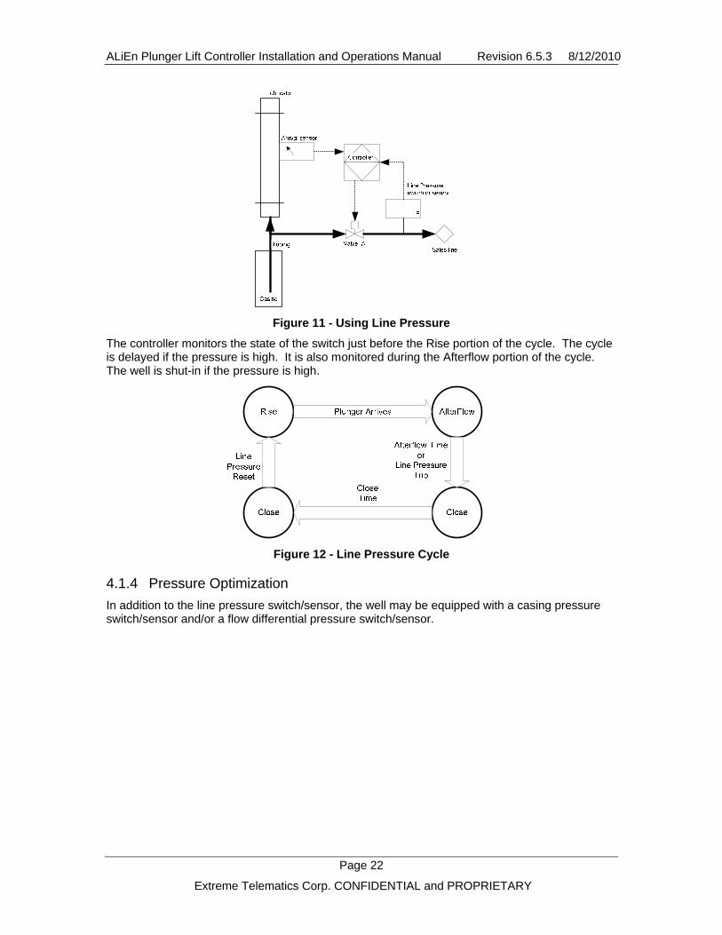
Figure 11 - Using Line Pressure
The controller monitors the state of the switch just before the Rise portion of the cycle. The cycle is delayed if the pressure is high. It is also monitored during the Afterflow portion of the cycle. The well is shut-in if the pressure is high.
Figure 12 - Line Pressure Cycle
4.1.4 Pressure Optimization
In addition to the line pressure switch/sensor, the well may be equipped with a casing pressure switch/sensor and/or a flow differential pressure switch/sensor.

ALiEn Plunger Lift Controller Installation and Operations Manual Revision 6.5.3 8/12/2010
Page 23
Extreme Telematics Corp. CONFIDENTIAL and PROPRIETARY
Figure 13 - Pressure Based Optimization
The following table describes the different optimization schemes that are used depending on the devices that are enabled.
Table 13 - Pressure Optimization Modes
Ref Line Pressure
Casing Pressure
Flow DP
Optimization
1 disabled disabled disabled none
2 disabled disabled switch 1
3 disabled disabled sensor 2
4 disabled switch disabled 3
5 disabled switch switch 1, 3
6 disabled switch sensor 2, 3
7 disabled sensor disabled 4
8 disabled sensor switch 1, 4
9 disabled sensor sensor 2, 4
10 switch disabled disabled none
11 switch disabled switch 1
12 switch disabled sensor 2
13 switch switch disabled 3
14 switch switch switch 1, 3
15 switch switch sensor 2, 3
16 switch sensor disabled 4, 6
17 switch sensor switch 1, 4, 6
18 switch sensor sensor 2, 4, 6
19 sensor disabled disabled none

ALiEn Plunger Lift Controller Installation and Operations Manual Revision 6.5.3 8/12/2010
Page 24
Extreme Telematics Corp. CONFIDENTIAL and PROPRIETARY
Ref Line Pressure
Casing Pressure
Flow DP
Optimization
20 sensor disabled switch 1
21 sensor disabled sensor 2, 5
22 sensor switch disabled 3
23 sensor switch switch 1, 3
24 sensor switch sensor 3, 5
25 sensor sensor disabled 6, 7
26 sensor sensor switch 1, 6, 7
27 sensor sensor sensor 5, 6, 7
1. Stay in Afterflow until the Afterflow Time expires AND: the Max Open Time expires or the Flow DP switch trips.
2. Stay in Afterflow until the Afterflow Time expires and: the Max Open Time expires or the Flow DP drops below an operator-entered threshold.
3. Monitor the Casing Pressure switch after the Close Time expires. Stay shut-in while the Casing Pressure switch is tripped.
4. Monitor the Casing Pressure sensor after the Close Time expires. Stay shut-in while the Casing Pressure is below an operator-entered set-point.
5. During Rise, Afterflow: Calculate the Flow Rate using a simplified orifice meter formula. Stay in Afterflow until the Afterflow Time expires. Stay in Afterflow until the Max Open Time expires or the Flow Rate drops below an operator-entered threshold. Calculate and save daily production volumes based on the calculated flow rate.
6. During Afterflow: Monitor the Casing Pressure to find its “minimum value”.2 Keep the well flowing until the Afterflow Time expires AND: the Max Open Time expires or the Casing Pressure exceeds the “minimum value” by an operator-entered set-point. See diagram below. Other algorithms are also available to monitor Casing Pressure in the Afterflow portion of the cycle.
7. During Close: After the Close or Extended Close Time expires, monitor the Casing/Line differential pressure. Start a new cycle when the Casing/Line pressure difference exceeds an operator-entered threshold.
2 Do not monitor Casing and Line pressure sensors within the Arrival Guard time of plunger arrival.

ALiEn Plunger Lift Controller Installation and Operations Manual Revision 6.5.3 8/12/2010
Page 25
Extreme Telematics Corp. CONFIDENTIAL and PROPRIETARY
The following diagram illustrates the controller behaviour when using various extended flow devices.
Figure 14 - Extended Afterflow Optimization
4.1.4.1 Casing Pressure
Casing Pressure can be used on its own or in combination with Line Pressure. This section discusses how Casing Pressure can be used on its own. Some of the optimization schemes behave the same when line pressure is turned on, while others will cause the controller to switch to using Casing Line Differential Pressure. The following controller actions will only take place if a Casing Pressure device has been enabled.
4.1.4.1.1 Close
The Casing Pressure is not monitored until the end of the Close portion of the cycle. Once the Close Time has expired, the well will be held closed until the Casing Pressure device has been reset.
Figure 15 - Casing Pressure Close Cycle
If a switch is used, it must be in the reset position and must stay there for at least the stable time. If the Casing Pressure Device Type is configured as a sensor, then the sensor value must exceed the Open Casing Pressure Reset Point and stay there for at least the Open Casing Pressure Stable Time.

ALiEn Plunger Lift Controller Installation and Operations Manual Revision 6.5.3 8/12/2010
Page 26
Extreme Telematics Corp. CONFIDENTIAL and PROPRIETARY
Figure 16 - Open Casing Pressure Reset Point
4.1.4.1.2 Afterflow/ Extended Afterflow
Figure 17 - Afterflow/Extended Afterflow Casing Pressure
During the Afterflow portion of the cycle, the Casing Pressure is monitored one of three different ways if the Casing Pressure Device Type has been configured as a sensor. If the Casing Pressure trips during Afterflow, the well is closed as soon as the Afterflow Time expires. If the Casing Pressure has not tripped by the end of the Afterflow Time, then the Casing Pressure will continue to be monitored during the Extended Afterflow portion of the cycle. A trip during the Extended Afterflow portion of the cycle will cause the well to be closed once the applicable Stable Time has been met. The following sections describe the different Casing Pressure monitors that can be configured.
4.1.4.1.2.1 Low Rise
The Low Rise method monitors the down slope of the Casing Pressure. Once the Casing Pressure stops decreasing, the current value is saved. This is used to determine how much the Casing Pressure has risen when the well begins to water in. Once the Casing Pressure has risen greater than the Close Casing Differential Pressure Trip Point and stays there for at least the time defined by the Close Casing Differential Pressure Stable Time, the well will be shut-in.
ALiEn Plunger Lift Controller Installation and Operations Manual Revision 6.5.3 8/12/2010
Page 27
Extreme Telematics Corp. CONFIDENTIAL and PROPRIETARY
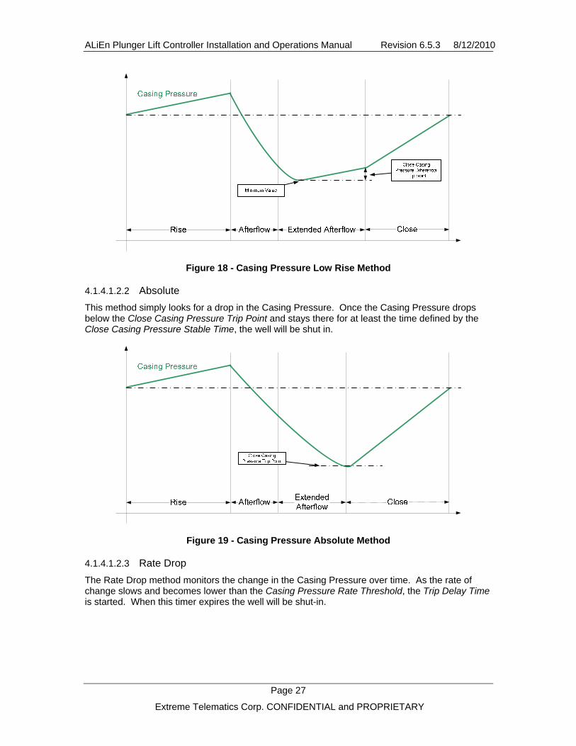
Figure 18 - Casing Pressure Low Rise Method
4.1.4.1.2.2 Absolute
This method simply looks for a drop in the Casing Pressure. Once the Casing Pressure drops below the Close Casing Pressure Trip Point and stays there for at least the time defined by the Close Casing Pressure Stable Time, the well will be shut in.
Figure 19 - Casing Pressure Absolute Method
4.1.4.1.2.3 Rate Drop
The Rate Drop method monitors the change in the Casing Pressure over time. As the rate of change slows and becomes lower than the Casing Pressure Rate Threshold, the Trip Delay Time is started. When this timer expires the well will be shut-in.

ALiEn Plunger Lift Controller Installation and Operations Manual Revision 6.5.3 8/12/2010
Page 28
Extreme Telematics Corp. CONFIDENTIAL and PROPRIETARY
Figure 20 - Casing Pressure Rate Drop Method
4.1.4.2 Casing Line Differential Pressure
If a Casing Pressure Sensor and a Line Pressure Sensor are both enabled, Casing Line Differential Pressure will be used to determine when the controller can move from Close to Open. The difference will be taken between these two values and then compared to the Open Casing Line Differential Pressure Reset Point. Once the differential exceeds the reset point and stays above it for at least the Open Casing Line Differential Pressure Stable Time, the well will open. Please note that casing pressure alone is used when determining when to go from open to close.
Figure 21 - Open Casing Line Differential Trip
4.1.4.3 Flow Differential Pressure
Flow DP Device Type can be configured as either a switch or sensor. When it is configured as a switch, it will automatically drop out of Extended Afterflow when the switch trips. A trip indicates that the differential is below a trip point set externally. The differential is proportional to the flow. A drop in flow is represented as a drop in differential. As the well begins to water in, the differential will decrease.

ALiEn Plunger Lift Controller Installation and Operations Manual Revision 6.5.3 8/12/2010
Page 29
Extreme Telematics Corp. CONFIDENTIAL and PROPRIETARY
When the Flow DP Device Type is enabled as sensor, the controller will behave in the same manner. The difference is that the Flow Differential Pressure Trip Point and Flow Differential Pressure Reset Point must be configured to tell the controller when to shut in the well. If a Line Pressure sensor is used in conjunction with a Flow Differential Pressure Sensor, then a flow rate can be estimated. Please refer to the Flow Rate section below.
4.1.4.4 Flow Rate
There are several ways to obtain a Flow Rate for optimization. They are discussed in detail in the sections below.
When the Flow Rate is available, the Extended Afterflow Time of the controller is optimized. If the Flow Rate is a numerical value, the well is shut-in when the Flow Rate drops below the Flow Rate Trip Point and remains there for at least the Flow Rate Stable Time.
The Flow Rate value is also used to provide an estimated daily production. The flow is summed over time and the resultant production numbers are shown in the daily logs, which can be viewed by pressing the History hot key.
4.1.4.4.1 Calculated
The flow rate can be calculated if a Line Pressure sensor and a Flow Differential Pressure Sensor are used. This method will require a set of orifice plate parameters to be entered in the Inputs menu. A Meter Factor is derived from a look up table using the Meter Run Size and Orifice Plate Size. The Gas Temperature and Gas Specific Gravity are entered by the installer and are NOT updated real time. This calculation will provide an estimated flow that can be used for optimization. Please note that the production values that are derived from the calculation are not suitable for custody transfer.
4.1.4.4.2 Switch
The Flow Rate Device Type can also be configured as a switch. This allows the well to be shut in when the switch trips. Since there is no value associated with the Flow Rate, production numbers will not be provided.
4.1.4.4.3 Virtual
This configuration for Flow Rate allows the well to be optimized based on a Flow Rate from another system. This mode of operation requires a Flow Rate to be written to a Modbus register. This incoming value is then compared against the Flow Rate Trip Point to determine when to shut-in the well. Since a value is available for Flow Rate, the production numbers are calculated and displayed in the daily logs.
4.1.4.4.4 Sensor
The Flow Rate Device Type can also be set to sensor which uses an analog input. This input value is scaled to provide a flow value. This option is currently available, but has not been tailored to match any specific flow sensor at this point. Development would be required to fully implement this solution.
4.1.5 Timer Optimization
Timer Optimization allows the well to be optimized based on the arrival time of the plunger, which can be derived from the plunger velocity and well depth. The actual plunger arrival time is compared to a Target Rise Time and adjustments are made to the flow or shut-in time of the well in order to optimize the performance of the well. The objective of this optimization is to cause the plunger to arrive at the Target Rise Time.
The algorithm uses a set of parameters to determine the percentage of time late or early that the plunger arrived. This percentage is then scaled and added to or subtracted from the Extended

ALiEn Plunger Lift Controller Installation and Operations Manual Revision 6.5.3 8/12/2010
Page 30
Extreme Telematics Corp. CONFIDENTIAL and PROPRIETARY
Afterflow Time or Extra Close Time, depending on which optimization mode has been selected. Please note that these timers starts at 0h00m00s. They can be configured to a higher value to allow the well to adjust the time up or down
In Afterflow Time Optimization, if the Extended Afterflow Time it is left at 0h00m00s, the well will only be able to flow longer, not shorter. This means that no adjustments can be made if the plunger arrives late. The Afterflow Time should be configured appropriately in this case so that the Extended Afterflow Time moves up over time (i.e. Afterflow Time is set to the minimum you ever want the well to flow for after the plunger arrives).
In Close Time Optimization, if the Extra Close Time is left at 0h00m00s, the well will only be able to shut in for longer, not shorter. This means that no adjustments can be made if the plunger arrives early. The Close Time should be configured appropriately in this case so that the Extra Close Time moves up over time (i.e. Close Time is set to the minimum you ever want the well closed for).
4.1.5.1 Timer Optimization Parameters
There are a number of parameters that are used for the Timer Optimization algorithm. They control the response that is generated to an early or late plunger arrival. The following sections outline the relationship between these parameters.
4.1.5.1.1 Rise Time (RTime)
The Rise Time is the window that the controller will wait for a plunger arrival to occur. An arrival after this window will be ignored. The Rise Time is used as part of the plunger late arrival window.
4.1.5.1.2 Target Rise Time (TRTime)
The Target Rise Time is the time that the plunger is expected to arrive when the well is producing most efficiently. This time should be calculated from the well depth and the desired average velocity of the plunger. If the plunger arrives on target, no adjustments are made. The Target Rise Time is used for both the early and late plunger arrival windows.
Target Rise
Rise Time
Figure 22 – Target Rise Time
4.1.5.1.3 Actual Rise Time (ARTime)
The Actual Rise Time is the time that the plunger took to rise to surface from the time that the controller opened the well. This time will always be less than the Rise Time. It is compared to the Target Rise Time to determine if we arrived early or late, and by how much.

ALiEn Plunger Lift Controller Installation and Operations Manual Revision 6.5.3 8/12/2010
Page 31
Extreme Telematics Corp. CONFIDENTIAL and PROPRIETARY
4.1.5.1.4 Miss Percentage (M%)
The Miss Percentage is determined by taking the amount of time the Target Rise Time is missed by and dividing it by the arrival window (early or late). The following shows the difference between a late arrival and an early arrival.
4.1.5.1.4.1 Early Arrival
An early arrival occurs when the plunger arrives before the Target Rise Time.
Target Rise
Actual Rise
Rise Time
Figure 23 - Early Arrival
The Miss Percentage is calculated by taking the difference between the Target Rise Time and Actual Rise Time and dividing by the Target Rise Time. This number will be a NEGATIVE number since the Actual Rise Time is less than the Target Rise Time.
%100% xTR
TRARM
Time
TimeTime
Where:
M% = Miss Percentage TRTime = Target Rise Time ARTime = Actual Rise Time
For example, if the Target Rise Time is 10 minutes and the Actual Rise Time is 9 minutes, the plunger arrived 1 minute early out of 10 minutes, which is a -10% miss.
%10%10010
109%
xM
4.1.5.1.4.2 Late Arrival
A late arrival occurs when the plunger arrives after the Target Rise Time.

ALiEn Plunger Lift Controller Installation and Operations Manual Revision 6.5.3 8/12/2010
Page 32
Extreme Telematics Corp. CONFIDENTIAL and PROPRIETARY
Target Rise
Actual Rise
Rise Time
Figure 24 - Late Arrival
The percentage late is calculated by taking the difference between the Actual Rise Time and Target Rise Time and dividing by the late window, which is the difference between the Rise Time and the Target Rise Time.
%100% xTRR
TRARM
TimeTime
TimeTime
Where:
M% = Miss Percentage TRTime = Target Rise Time ARTime = Actual Rise Time RTime = Rise Time
For example, if the Rise Time is 20 minutes, the Target Rise Time is 10 minutes and the Actual Rise Time is 11 minutes, the plunger arrived 1 minute late out of 10 minutes, which is a 10% miss.
%10%1001020
1011%
xM
4.1.5.1.5 Timer Mode (TM)
The Timer Mode parameter lets you adjust the magnitude of response to an early or late arrival. There are three different modes: A, B, and C. Mode A is the least aggressive and will substantially dampen the amount of flow time that is added or subtracted. This will make more stable, smaller adjustments, but the well will take longer to reach to the Target Rise Time. Mode C is the most aggressive and will provide less dampening. This will make larger adjustments, but may cause more swings in the plunger arrival time.
The following table shows the amount of the Miss Percentage that is applied to the Extended Afterflow Percentage or the Extra Close Percentage.
Table 14 - Timer Modes
Timer Mode Scale
A 1%
B 5%
C 10%

ALiEn Plunger Lift Controller Installation and Operations Manual Revision 6.5.3 8/12/2010
Page 33
Extreme Telematics Corp. CONFIDENTIAL and PROPRIETARY
4.1.5.2 Afterflow Time Optimization
The goal of Afterflow Optimization is to modify the amount of flow time in order to get the plunger to arrive at the Target Rise Time. The Afterflow Time acts as a minimum amount of flow time, while the Extended Afterflow Time will increase and decrease automatically based on the arrival time of the plunger.
If the plunger arrives late, the well will shut-in earlier in to send the plunger down sooner (makes more trips). If the plunger arrives early, the well will be allowed to flow longer (makes less trips). The amount of additional flow time that we are currently using is stored as Extended Afterflow Percentage (EAF%).
The following parameters summarize the calculations that are done to get the current Extended Afterflow Time.
4.1.5.2.1 Afterflow Time (AFTime)
The Afterflow Time is configured as part of the normal setup of the controller. The Afterflow Time is used to flow the well for a MINIMUM amount of time after the plunger has arrived. Changes in devices or timer optimization settings will not affect the Afterflow Time.
4.1.5.2.2 Max Open Time (MOTime)
The Max Open Time defines the maximum amount of time that the well is allowed to stay open including Actual Rise, Afterflow and Extended Afterflow Time. In Afterflow Time Optimization, the Max Open Time is used to find the Remaining Flow Time.
4.1.5.2.3 Remaining Flow Time (RFTime)
The Remaining Flow Time is the amount of flow time that is left after the plunger arrives and Afterflow is complete, but before the Max Open Time expires.
Figure 25 – Remaining Flow Time
This time is used in conjunction with the Extended Afterflow Percentage to give us Extended Afterflow Time.
TimeTimeTimeTime AFARMORF
Where: RFTime = Remaining Flow Time MOTime = Max Open Time

ALiEn Plunger Lift Controller Installation and Operations Manual Revision 6.5.3 8/12/2010
Page 34
Extreme Telematics Corp. CONFIDENTIAL and PROPRIETARY
ARTime = Actual Rise Time AFTime = Afterflow Time
4.1.5.2.4 Extended Afterflow Percentage (EAF%)
The Extended Afterflow Percentage keeps track of how much of the Remaining Flow Time to make use of. This percentage is adjusted after each plunger arrival. The percentage is decreased for each late arrival and is increased for each early arrival. The minimum for this parameter is 0.0% and the maximum is 100.0%.
Figure 26 - EAF%
The amount of change is proportional to the Miss Percentage as defined earlier. The Miss Percentage is scaled by the Timer Mode and subtracted from the Extended Afterflow Percentage.
)( %%% TMMEAFEAF
Where: EAF% = Extended Afterflow Percentage M% = Miss Percentage TM = Timer Mode
For example, if the Miss Percentage was -10% (arrived 10% early) and the Timer Mode was set to A (1%), then 0.1% would be added to the Extended Afterflow Percentage.
%)1%10(%% EAFEAF
%1.0%% EAFEAF
Conversely, if the Miss Percentage was 10% (arrived 10% late) and the Timer Mode was set to A (1%), then 0.1% would be subtracted from the Extended Afterflow Percentage.
%)1%10(%% EAFEAF
%1.0%% EAFEAF
4.1.5.2.5 Extended Afterflow Time (EAFTime)
To get the current Extended Afterflow Time, the Extended Afterflow Percentage is multiplied by the Remaining Flow Time.
TimeTime RFEAFEA %

ALiEn Plunger Lift Controller Installation and Operations Manual Revision 6.5.3 8/12/2010
Page 35
Extreme Telematics Corp. CONFIDENTIAL and PROPRIETARY
Where: EAFTime = Extended Afterflow Time EAF% = Extended Afterflow Percentage RFTime = Remaining Flow Time
4.1.5.3 Close Time Optimization
Close Optimization is used to modify the amount of time the well is closed in order to get the plunger to arrive at the Target Rise Time. The Close Time acts as a minimum amount of close, while the Extra Close Time is an additional controller state that is used to shut-in the well for a variable amount of time. The amount of additional close time that we are currently using is stored as Extra Close Percentage (EC%).
The following parameters summarize the calculations that are done to get the current Extra Close Time.
4.1.5.3.1 Close Time (CTime)
The Close Time is configured as part of the normal setup of the controller. The Close Time is used to shut-in the well for a MINIMUM amount of time. Changes in timer optimization settings will not affect the Close Time, but devices such as Line Pressure and Casing Pressure can hold the controller in close.
4.1.5.3.2 Max Close Time (MCTime)
The Max Close Time defines the maximum amount of time that the well is allowed to stay closed including Close, Non-Arrival Close, and Extra Close Time. In Close Time Optimization, the Max Close Time is used to find the Remaining Close Time. Please note that the well may stay closed longer due to devices such as Line Pressure or Casing Pressure.
4.1.5.3.3 Remaining Close Time (RCTime)
The Remaining Close Time is the amount of shut-in time that is left after the Close Time has expired and before the Max Close Time is reached.
Figure 27 – Remaining Close Time
This time is used in conjunction with the Extra Close Percentage to give us Extra Close Time.
TimeTimeTime CMCRC
Where: RCTime = Remaining Close Time

ALiEn Plunger Lift Controller Installation and Operations Manual Revision 6.5.3 8/12/2010
Page 36
Extreme Telematics Corp. CONFIDENTIAL and PROPRIETARY
MCTime = Max Close Time CTime = Close Time
4.1.5.3.4 Extra Close Percentage (EC%)
The Extra Close Percentage keeps track of how much of the Remaining Close Time to make use of. This percentage is adjusted after each plunger arrival. If the plunger arrives late, the well will be shut-in longer. If the plunger arrives early, the well will be shut-in less. The minimum for this parameter is 0% and the maximum is 100%.
Figure 28 - EC%
The amount of change that is made is proportional to the Miss Percentage as defined earlier. The Miss Percentage is scaled by the Timer Mode and added to the Extra Close Percentage.
)( %%% TMMECEC
Where: EC% = Extra Close Percentage M% = Miss Percentage TM = Timer Mode
For example, if the Miss Percentage was -10% (arrived 10% early) and the Timer Mode was set to A (1%), then 0.1% would be subtracted from the Extra Close Percentage.
%)1%10(%% ECEC
%1.0%% ECEC
Conversely, if the Miss Percentage was 10% (arrived 10% late) and the Timer Mode was set to A (1%), then 0.1% would be added to the Extra Close Percentage.
%)1%10(%% ECEC
%1.0%% ECEC
4.1.5.3.5 Extra Close Time (ECTime)
To get the current Extra Close Time, the Extra Close Percentage is multiplied by the Remaining Close Time.

ALiEn Plunger Lift Controller Installation and Operations Manual Revision 6.5.3 8/12/2010
Page 37
Extreme Telematics Corp. CONFIDENTIAL and PROPRIETARY
TimeTime RCECEC %
Where: ECTime = Extra Close Time EC% = Extra Close Percentage RCTime = Remaining Close Time
4.1.6 Dual Valve
The well may also be equipped with a second valve (Valve B). This valve may be installed in one of 3 configurations. These configurations are illustrated and described below.
4.1.6.1 Top Valve
Figure 29 - Top Valve Well Configuration
The Valve B Type must be set to line and the Afterflow Valve Configuration must be set to A in order to operate the controller in a Top Valve configuration.
During the Rise portion of the cycle, Valve B is open and Valve A is closed. The location of Valve B is such that the plunger will be driven fully into the lubricator upon arrival without requiring excessive (i.e. sub-optimal) velocity. A short time after the plunger arrival, Valve A is opened and Valve B is closed. The location of Valve A causes the Plunger to be held within the Lubricator while gas is flowing with sufficient pressure. In this configuration, the well may be equipped with an auto-catcher which is driven from the Valve B gas supply line.
Plunger ArrivesAfterFlow:Valve A
open
Close
Rise:Valve B
open
CloseTime
AfterflowTime
Figure 30 - Top Valve Operation

ALiEn Plunger Lift Controller Installation and Operations Manual Revision 6.5.3 8/12/2010
Page 38
Extreme Telematics Corp. CONFIDENTIAL and PROPRIETARY
4.1.6.2 Flow Tee
Figure 31 - Flow Tee Well Configuration
The Top Valve configuration has the disadvantage of requiring that a valve gas control line be installed between the separator shack and well-head. To avoid this, a Flow Tee configuration is often used. Operation is the same as for the Top valve except that, in the Afterflow portion of the cycle, both valves are left open.
To achieve this configuration, the Valve B Type must be set to line and the Afterflow Valve Configuration must be set to A/B.
Figure 32 - Flow Tee Operation

ALiEn Plunger Lift Controller Installation and Operations Manual Revision 6.5.3 8/12/2010
Page 39
Extreme Telematics Corp. CONFIDENTIAL and PROPRIETARY
4.1.6.3 Tank Valve
Figure 33 - Tank Valve Well Configuration
If Valve B is connected to a Tank, Valve A is opened at the start of the Rise portion of the cycle. If the plunger does not arrive within a specified time, then the valves are toggled (i.e. simultaneously open Valve B and close Valve A). When the plunger arrives, the valves may be toggled again. The purpose of the tank is to assist in plunger lift by exerting less back pressure on the well tubing than that exerted from the sales Line.
For each valve, the controller is equipped with a solenoid which directs the flow of low pressure gas to either an “open” or “close” line connected to a valve. This, in turn, controls the flow of higher pressure gas which actuates the valve position. The controller emits separate open and close pulse for each valve.
4.1.7 Low Battery
The controller is designed to handle a number of failure conditions, most of which have already been discussed. If the controller senses that the battery is low, it will take action to ensure that the valve(s) are left in a known state. When a low battery condition has occurred, the controller will actuate the valve(s) and then go into a Stopped state. The controller will remain in this state until the battery has recovered or an operator has intervened.
The state that the valve is placed in when a low battery condition occurs is based on the Low Battery Fail Mode parameter that is found in the Alarms menu.

ALiEn Plunger Lift Controller Installation and Operations Manual Revision 6.5.3 8/12/2010
Page 40
Extreme Telematics Corp. CONFIDENTIAL and PROPRIETARY
5 Modbus Communications The controller is equipped with an RS-485 port which is designed primarily to provide communications to a SCADA system. This port provides most of the functions available from the front panel user interface using the Modbus protocol. The Modbus Communications User’s Guide discusses the physical connections, communications settings, and the available registers.
6 Installation
6.1 Physical Connections
The following is an outline of the locations that input devices can be wired to:
Valves
LPSwitch
CPSwitch
FDPSwitch
LPSensor
CP/FDPSensor
ArrivalSensor
Figure 34 - Alien Wiring Diagram
Location Devices To Connect Description
Battery 6V Battery Only use a 6V intrinsically safe ETC battery.
Solar Solar Panel Use a 3W ETC Solar Panel
Valve 1 Valve A Solenoid Only use an intrinsically safe ETC approved valve solenoid.
Valve 2 Valve B Solenoid Only use an intrinsically safe ETC approved valve solenoid.
Valve 3 Valve C Solenoid Only use an intrinsically safe ETC approved valve solenoid.
Valve 4 Valve D Solenoid (Auto Catcher Valve) Only use an intrinsically safe ETC approved valve solenoid.

ALiEn Plunger Lift Controller Installation and Operations Manual Revision 6.5.3 8/12/2010
Page 41
Extreme Telematics Corp. CONFIDENTIAL and PROPRIETARY
Location Devices To Connect Description
DI 1 Arrival Sensor Connect signal and ground of a 2 or 3 wire plunger arrival sensor.
DI 2 Line Pressure Switch Switch contacts that can be configured to cause a trip on a switch closing or opening.
DI 3 Casing Pressure Switch Switch contacts that can be configured to cause a trip on a switch closing or opening.
DI 4 Flow/Flow DP Switch Switch contacts that can be configured to cause a trip on a switch closing or opening.
AI 1 Line Pressure Sensor Use AST intrinsically safe, low power pressure transducer provided by ETC
Casing Pressure Use AST intrinsically safe, low power pressure transducer provided by ETC
Flow Differential Pressure Use low power Rosemount 1151 differential pressure transmitter.
AI 2
Flow Sensor This feature is currently not fully implemented and requires customer input.
DO 1 Arrival Sensor Power or Field Connectable Configure this output to power the arrival sensor or to mimic a valve. This is field connectable, but must meet the entity parameters found in the ETC Gas Valve Controller Installation Manual.
DO 2 Arrival Sensor Power or Field Connectable Configure this output to power the arrival sensor or to mimic a valve. This is field connectable, but must meet the entity parameters found in the ETC Gas Valve Controller Installation Manual.
AO 1 Not currently implemented Provides a 4 – 20 mA output signal.
COM 1 Differential RS485 device Field connectable to a 2 wire RS485 interface. The connected device must meet the entity parameters found in the ETC Gas Valve Controller Installation Manual.

ALiEn Plunger Lift Controller Installation and Operations Manual Revision 6.5.3 8/12/2010
Page 42
Extreme Telematics Corp. CONFIDENTIAL and PROPRIETARY
Note: support for a 3 wire arrival sensor has been included but must be configured through the Outputs menu. By default, the power for the 3 wire sensor is provided through the DO1>SIG connection.
6.2 Connecting Power
The following steps must be performed in the specified order to ensure that the battery properly charges:
1. Connect the Battery to the +/- Battery terminals on the left hand side of the controller
2. Connect the solar panel to the +/- Solar terminals
Note: If the controller is not hooked up to power in this order, the battery will not charge.
7 Troubleshooting The following outlines a number of common issues that may be encountered.
Table 15 - Troubleshooting Guide
Issue Cause Resolution
The fuse is blown on the battery
Return to ETC to be repaired. To avoid this issue, make sure to avoid shorting the battery connections.
Battery is unplugged or there is a loose connection
Plug in the battery and check all connections
Battery is dead Charge the battery as per the directions on the side of the battery. If it does not hold a charge, contact ETC to purchase a new battery.
The display won’t come on when the battery is plugged in.
Software has been erased Reprogram the software using the software upgrade procedure.
A key is stuck on the keypad
The keypad will need to be replaced. Please call ETC to arrange for the controller to be repaired.
Pressing a button does not produce the desired response.
The main core of the controller has been shocked
The controller core must be replaced. Please call ETC to arrange for the controller to be repaired. To avoid this, always transport the controller board in a static protection bag and avoid touching any exposed connections along the back of the controller without appropriate grounding.
Cannot Log in to the Setup Menu
You have forgotten your operator/installer ID.
If the Operator ID has been forgotten, use the Installer ID. If the Installer ID has been forgotten, ETC can generate a new ID on a per controller basis.

ALiEn Plunger Lift Controller Installation and Operations Manual Revision 6.5.3 8/12/2010
Page 43
Extreme Telematics Corp. CONFIDENTIAL and PROPRIETARY
Issue Cause Resolution
Cannot see the Optimization menu item
No optimization schemes are enabled on this controller
Contact ETC to purchase an optimization feature key.
Cannot see the Modbus menu item
Modbus communications has not been enabled on this controller
Contact ETC to purchase a Modbus communications feature key.
Cannot turn on Valve B Valve B operation has not been enabled on this controller.
Contact ETC to obtain a Valve B feature key.
Timer Optimization adjustments are too large
The algorithm is setup to be too aggressive.
Try using a different Timer Optimization mode. Mode A is the least aggressive.
Timer Optimization takes too long to adjust to the right value
The algorithm is not setup to be aggressive enough.
Try using a different Timer Optimization mode. Mode B and C are more aggressive than the default, A.
Fast Trips are disabled Set the Fast Trips in the Alarms menu to something other than disabled.
Fast Trips do not shut in the well
The fast trip alarm mode is set to fail open
Change the Fast Trip Fail Mode to Closed in the Alarms menu.
Non-Arrivals are disabled Set the Non-Arrivals in the Alarms menu to something other than disabled.
Non-Arrivals do not shut in the well
The non-arrival alarm mode is set to fail open
Change the Non-Arrival Fail Mode to Closed in the Alarms menu.
The battery is low Replace the battery and ensure that the solar panel is connected and positioned correctly.
Too many fast trips have occurred
Correct the issue with the well and set the controller to resume normal operation.
Controller is sitting in the stopped state
Too many non-arrivals have occurred
Correct the issue with the well and set the controller to resume normal operation.
8 Support
8.1 Software Upgrade
On occasion, software upgrades are made available. These releases will contain new features as well as resolutions to issues found in the product. The release notes describe the changes that are available in each release. The new software can be downloaded through the communications port whether the Modbus option is enabled or not.
It is recommended that the controller be removed from the well before the upgrade is performed as the valve operation cannot be trusted during the upgrade.

ALiEn Plunger Lift Controller Installation and Operations Manual Revision 6.5.3 8/12/2010
Page 44
Extreme Telematics Corp. CONFIDENTIAL and PROPRIETARY
8.1.1 Prerequisites
The following equipment is required to upgrade the controller: Battery Laptop with a USB port USB to RS485 converter Latest Firmware file from Extreme Telematics Corp.
8.1.2 Setup
1. Ensure that the USB to RS485 adapter is configured in 2 wire mode. 2. Wire the RDA(-) to COM1 B and RDB(+) to COM1 A. The GND can be wired to the
unlabelled connection on COM1 between A and B, but is not necessary. 3. Plug adapter into an available USB port 4. Install the drivers that were provided with the USB to RS485 converter
8.1.3 Upgrade Procedure
1. Hold the Cycle Log button down 2. Plug the battery into the controller 3. Release the Cycle Log button 4. If the controller does not enter the upgrade program, the previous software that was
installed may not include this program. Please contact ETC. 5. Follow the prompts on the screen to erase the current firmware. To abort the upgrade
process at this point, unplug the battery. 6. When prompted to do so, download the firmware
a. Open the ETC Upgrade Utility b. Browse to the latest ETC file that was provided by Extreme Telematics Corp. c. Select the appropriate COM port from the drop down list. d. Click the Connect button e. Select Download
7. The display on the controller should change to show the status of the download and a progress bar should appear on the screen, showing how much code has been downloaded.
8. When the download is complete, the controller should start normally.
8.1.4 Upgrade Errors
During the download of a firmware image, errors may occasionally occur. If this does happen, simply repeat the procedure again, making sure to erase the current firmware. If an error occurs multiple times in a row, contact Extreme Telematics Corp.
The following is a list of errors that may be seen: Err 1 – Invalid file format. The Bootloader found information in the serial stream that
did not match the expected format. This could be a transmission error or an error with the file.
Err 2 – Dropped Characters. While parsing the incoming stream, extra characters were detected. This typically means that some data was lost.
Err 3 – Character Buffer Overrun. Incoming characters were lost because the controller was too busy processing to service the incoming data. Please contact ETC if this occurs.
Err 4 – Flash Buffer Overrun. This means that there is a back log saving to the controller. Please contact ETC if this occurs.
Err 5 – Character Buffer Underrun. The controller was expecting to parse more incoming characters, but there are none available. Please contact ETC if this occurs.

ALiEn Plunger Lift Controller Installation and Operations Manual Revision 6.5.3 8/12/2010
Page 45
Extreme Telematics Corp. CONFIDENTIAL and PROPRIETARY
8.2 Replacement Parts and Accessories
Several replacement parts or accessories are available for purchase. These items are listed in the table below with their associated part numbers. Please contact sales for the current price list.
Table 16 - Available Replacement Parts and Accessories
Part Number Name Description
ET-10000-1007-0001 Single Valve Assembly Includes a pneumatic valve solenoid, 2 3/8” NPT elbows, an O Ring, and Nylon Lock Nut
ET-10000-1007-0002 Dual Valve Assembly Includes 2 pneumatic valve solenoids, 2 3/8” NPT elbows, a Tee, a 3/8” NPT connector, 2 O Rings, and 2 Nylon Lock Nuts
ET-10000-1007-0005 Dual Valve Upgrade Kit Includes a pneumatic valve solenoid, a Tee, a 3/8” NPT connector, an O Ring, and Nylon Lock Nut
ET-00000-0000-0230 Valve Solenoid Core Includes the plastic molded solenoid core and wires
ET-00000-0000-0231 Valve Piston and Spring Includes the internal valve piston and attached spring assembly
ET-00000-0000-0225 Solar Panel 6V, 3W CSA Class 1 Div 1 Intrinsically safe solar panel
ET-10000-1011-0000 6V Battery CSA approved replacement battery with intrinsically safe protection.
Coming Soon Arrival Sensor Use with the Alien controller to detect a plunger arrival.
ET-00000-0000-0070 4 Pin Connector 4 Pin Weidmuller connector
ET-00000-0000-0009 8 Pin Connector 8 Pin Weidmuller connector
ET-00000-0000-0180 Captive Screw Small screws that are used to attach the controller to the enclosure.
S0000001
Timer Optimization License Key
Allows the Extended Afterflow or Extra Close times to be modified based on the arrival time of the plunger.
S0000002
Pressure Optimization License Key
Allows pressure devices to be used to optimize both the close and extended Afterflow portions of the cycle.
S0000003
Modbus Communications License Key
Allows for remote communications via Modbus.

ALiEn Plunger Lift Controller Installation and Operations Manual Revision 6.5.3 8/12/2010
Page 46
Extreme Telematics Corp. CONFIDENTIAL and PROPRIETARY
8.3 Technical Support
8.3.1 Contacting Support
Support is available from your current service company. If an issue does arise, they should be the first point of contact. Service companies that are currently authorized distributors of the Alien can contact us in the following ways:
8.3.1.1 Web
Please visit our website at http://www.ETCorp.ca.
8.3.1.2 Phone
ETC support can be contacted via phone at our office in Calgary, AB at (403) 290-6300 Mon – Fri, 9:00 am to 5:00 pm MST. Authorized distributors will be provided information on how to contact someone outside the normal business hours listed above.
8.3.2 Identifying the Issue
Please take the time to identify the issue that is being experienced. Many issues can be resolved by simply upgrading the controller to the latest software. If the issue still persists, please try and determine if there is an issue with the software or hardware. Here are some common indications of each type of issue:
8.3.2.1 Hardware
Battery is not charging
Some display pixels do not power up
The controller display does not come up and the controller does not draw any current
A key is stuck
8.3.2.2 Firmware
The controller restarts itself (goes back to close at an incorrect time)
There are entries in the error log (Located in the System menu)
Controller behaviour is erratic
The same issue happens across multiple controllers
8.3.3 Reporting Software Issues
We strive to provide the best software possible that is free of defects. As with any controller, there may be issues. When issues do arise, please do the following:
Copy down any errors that are found in the error log
Note the controller configuration
Note what was being done on the controller when the issue occurred
Note the serial number and version number of the controller that experienced the issue
Detail instructions on how to repeat the issue if possible

ALiEn Plunger Lift Controller Installation and Operations Manual Revision 6.5.3 8/12/2010
Page 47
Extreme Telematics Corp. CONFIDENTIAL and PROPRIETARY
8.3.4 Repair Process
Please contact ETC and arrange to have the controller repaired. Please be ready to explain the issues that are being experienced. A detailed account of the problem will be required so that the issue can addressed in a timely fashion. Returned controllers will take approximately 4 – 6 weeks to be diagnosed and resolved.