Algorithmic sketchbook partbsubmission
43
ALGORITHMIC SKETCHBOOOK ALYSSA MAREE SANTOMARTINO (585168) ABPL30048: STUDIO AIR SEMESTER 1, 2014 UNIVERSITY OF MELBOURNE TUTORS: Haslett Grounds and Brad Elias Studio #11
-
Upload
alyssa-santomartino -
Category
Documents
-
view
238 -
download
2
description
Â
Transcript of Algorithmic sketchbook partbsubmission

ALGORITHMIC SKETCHBOOOKALYSSA MAREE SANTOMARTINO (585168)
ABPL30048: STUDIO AIRSEMESTER 1, 2014UNIVERSITY OF MELBOURNE
TUTORS: Haslett Grounds and Brad Elias Studio #11

3
CONTENTSLOFTING CURVES IN GRASSHOPPER UNDERSTANDING GEOMETRY,
TRANSFORMATIONS AND INTERSECTIONS COMPOSITION AND GENERATION
POINT ATTRACTORS
LAGI BREIF APPLICATIONS
EVALUATING AND GRAPHING FIELDS
GRAPH CANTILLEVERS
IMAGE SAMPLING
REGENERATING A DESIGN
THE TRAVELING SALESMAN
GRADIENT DECENT
FRACTAL PATTERNS
KANGAROO AND WEAVE-A-BIRD PLUG-INS
MATRIX DESIGNS
DIGITAL PROTOTYPING
DIGITAL TO PHYSICAL PROTOTYPING
4-5
6-8
9-11
12-14
15
16-18
18-20
20-22
22-24
24-28
28-30
30-36
36-39
39-42
36-39
39-42
A.1
A.2
A.3
B.1
B.1
B.2
B.2
B.2
B.2
B.2
B.5
B.5
B.5
B.5
B.5
B.5

4
A.1 : LOFTING CURVES IN GRASSHOPPER
Learning to use the programs Rhino and Grass-hopper in conjunction was the main agenda of this week’s exercise. In doing so we were instructed to create a set of curves, lofting them first through rhino and then through grasshopper. From this the importance of grasshopper was seen.
The curves of the shape were drawn in rhino and then referenced in Grasshopper. By doing so a loft which could be manipulated was constructed. The top image displays the manipulation of the first loft to the last. After each manipulation the result was ‘baked’ from grasshopper into Rhino. The grass-hopper base is the red shaded object in the bottom left image. Here we can see the working process of manipulation.
The left screen-grab shows the ‘bake’ having just been performed. The red curves can be seen un-derneath. The shape has been derived from these curves which are red as they are connected to grasshopper.
The bottom right screen-grab shows the initial lofted curve I made through the Rhino ‘loft’ command. Whilst this may be a faster method originally, manipula-tion is not able to be completed with ease. Instead of the loft moving with the curves as the control points are moves, as it does in Grasshopper, the loft re-mains stationary, only the curves themselves moving.

5
Within a box I experimented in creating 3D cells. They were then taken out from the box and ran-domly deleted to play with different forms. This was done with the Voroni3D command which cre-ated the cells around a selection of points I created within the box.
I proceeded to use a similar concept on a lofted form which I had created. This time using the Oc-tree command, I placed points on my surface and boxes were created on it. This can be seen in the screen grab below.
At the suggestion of the video, I tried to find an output which I could input by surface into. I tried to create a panelling system with a square, which I made on grasshopper. It be-came a little too com-plex and I was unable to make panels on my lofted shape.

6
A.2 : UNDERSTANDING GEOMETRY, TRANSFORMATIONS AND INTERSECTIONS
In the last technical video, I used the technique of creating surfaces on grasshopper, between points in rhino, to make a 3 dimensional hexagon. I then baked this out.
By linking in a lofted surface to Grasshopper, and using the Mesh Brep command, I was able to create a paneled surface for my loft and also my 3D box. After baking this out I could potentially lay this out and have it laser cut, just like we did for virtual environments.
This week’s tutorial video’s introduced us to creating surfaces from vectors and points and then mesh-ing these surfaces.
This screengrab shows how to add together two different vec-tors to create one. Two different ways of doing this was explored in Grasshopper. While they achieve the same result, one uses less plug-ins.
This second screengrab indicates how I came to create a rectangle from a plane in grasshopper. This allowed me to have a fully static and changeable rectangle to work with.

7
The other video’s introduced transforming curves into other objects. I was able to create this arched surface, which I then baked out to use in Rhino, from two curves.
I learnt how to create a plane on an individual curve, and then create a shape within that plane which can move along the curve. This could allow me to create multiple ribs around a curve, allowing me to create a specific path for the ribs to follow.
I explored, through creating a set of closed oval curves, creating frames through the offset plug-in. This was an interesting concept which could help me in creating a sculptural design for my project
One of the video’s had us creating a shape which we would contour under. This allowed us to form panels which could potentially be laser cut. We were also taught how to use grasshopper to lay the panels out. Even though I copied exactly what the video said, I was not able to make the panels. All of the panels were pasted on top of one another, even though I tried to separate them. I was not successful with using the orient command.

8
I also had issues with using the planar command to create a flat plane at the center of an object. For some reason my planes were massive in comparison to the ones in the video. I could not avaerage them out to find the central point.
I was interested in learning about notching from creating a circle on a plane between two surfaces. This would be extremely helpful for manufacturing purposes.
offsetting the angle Creating different parts to the circle
Ofsetting the line
Creating a notch for the material to fit into. Obvious-ly the notch has been exaggerated here
Conturing a sur-face
The contouring was placed against an off-setted surface to create contour lines.
By creating a Brep component out of subtracting different extruded shapes from my square (the Boolean subtract command in Rhino) I was able to use what I learnt in the drift-wood
9
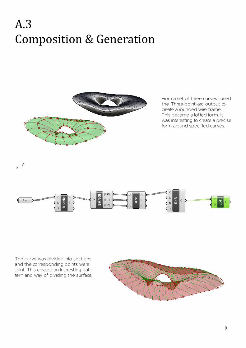
A.3Composition & Generation
The curve was divided into sections and the corresponding points were joint. This created an interesting pat-tern and way of dividing the surface.
From a set of three curves I used the ’Three-point-arc’ output to create a rounded wire frame. This became a lofted form. It was interesting to create a precise form around specified curves.

10
From a flat surface, which was linked into grasshopper through the surface input, was divided and flattened to become a Voronoi 2D Patterned surface. Here I experimented with different uses of the Voronoi tool using sliders to change the amount of panels, as well as the true false command within the panels.
I had some issues with connecting the Voronoi to my extruded surface and Culled Pattern. However I was still able to achieve what was happening in the video’s, my rectangular boundary square was just massive.
I decided to try other inputs within the Triangulation tab. Some worked when I inputed my extruded surface and/or culled pattern.
Voronoi 3D
Delaunay Edges
Proximity 2D

11
I then lofted the shape and made this mush-room like object.
Using another set of random curves which I created I attempted to repeat what I had learnt in the first video. This attempt was successful. These are the three curves I made.
I followed the same process, using the explode tree component to create points which the arc could connect to.
I then went back into Rhino and adjusted the control points randomly on the shape. This change was replicated within grasshopper and I was able to create a different shape from a similar set of curves.
12
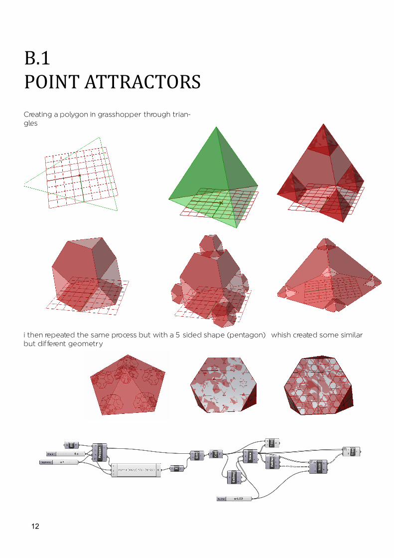
B.1POINT ATTRACTORSCreating a polygon in grasshopper through trian-gles
i then repeated the same process but with a 5 sided shape (pentagon) whish created some similar but different geometry

13
POINT ATTRACTORSstarting with one point and then moving onto two i can see how the points are attractiing the arrows dependig on where i moves them
this pont attraction is more clear-ly seen through the use of the colours,. I tries a few different parameters to see the different colour options
The point Attractoes were then applied to a lofted surface. Circles (their radius and number) were scaled dependant on their prox-imty to the point

14
Through the attachment of expressions and evaluations i was able to change the movement of the circles and how they were mixed to the loft. I used Cos, Floor and fix, as well as a number of x and y combinations
15
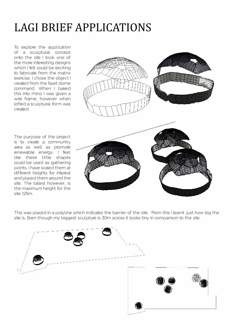
LAGI BRIEF APPLICATIONSTo explore the application of a sculptural concept onto the site I took one of the more interesting designs which I felt could be exciting to fabricate from the matrix exercise. I chose the object I created from the facet dome command. When I baked this into rhino I was given a wire frame, however when lofted a sculptural form was created.
The purpose of the project is to create a community area as well as promote renewable energy. I feel like these little shapes could be used as gathering points. I have scaled them at different heights for interest and placed them around the site. The tallest however, is the maximum height for the site 125m.
This was placed in a polyline which indicates the barrier of the site. From this I learnt just how big the site is. Even though my biggest sculpture is 30m across it looks tiny in comparison to the site.
16
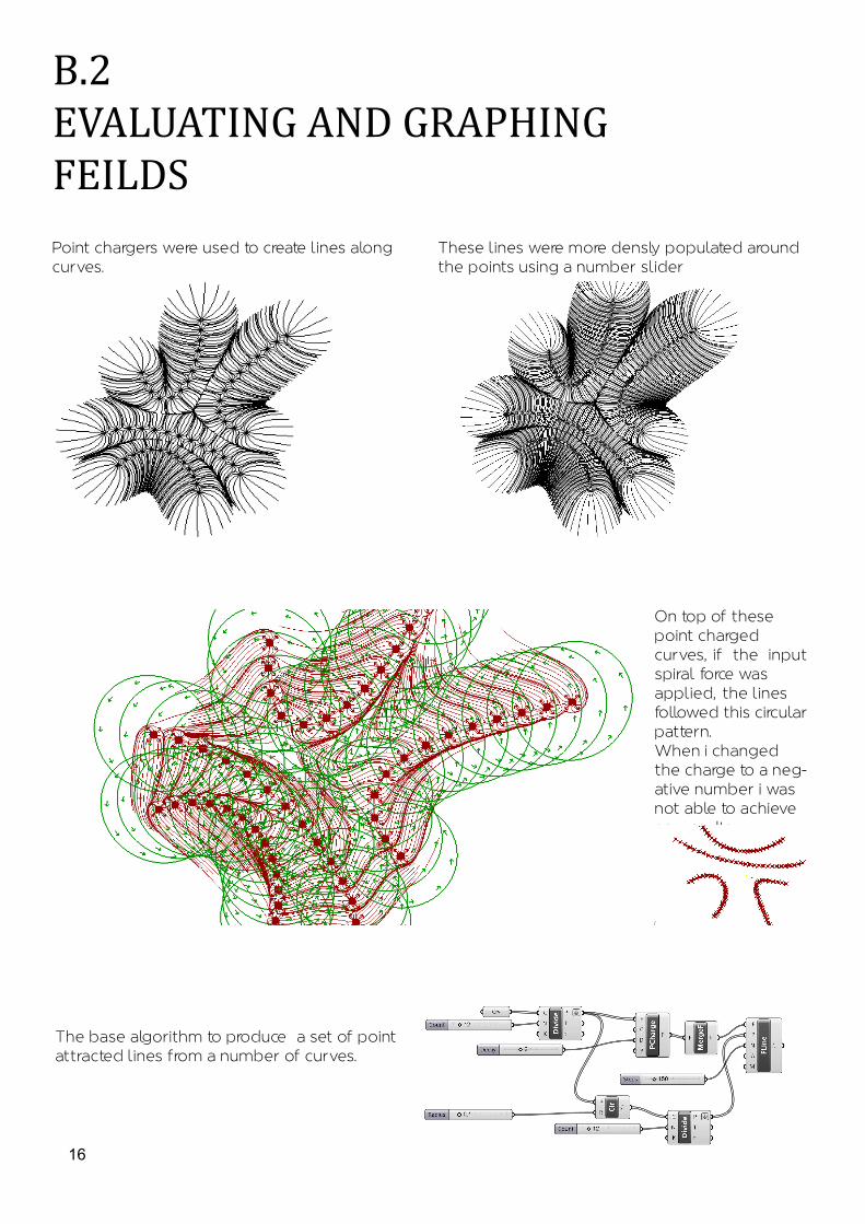
B.2EVALUATING AND GRAPHING FEILDSPoint chargers were used to create lines along curves.
These lines were more densly populated around the points using a number slider
On top of these point charged curves, if the input spiral force was applied, the lines followed this circular pattern. When i changed the charge to a neg-ative number i was not able to achieve any results
The base algorithm to produce a set of point attracted lines from a number of curves.
17
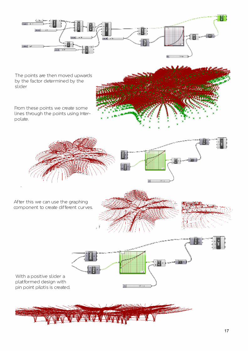
The points are then moved upwards by the factor determined by the slider
From these points we create some lines through the points using Inter-polate.
After this we can use the graphing component to create different curves.
With a positive slider a platformed design with pin point piloti’s is created.

18
B.2GRAPH CONTROLERS
Use of the Bizzar input created hexegonal patterns around the circles which were created through a graph map. These circles radii can be adjusted with a slider.
With the input of a cull pattern, the points which i created on the circles were inputed at a true/false pattern.
35 points on a circle 87 points on a circle
Cull pattern output

19
Adjusting the panel inputted into the vorrinoi to a true/false/false rather than a true/false, as ap-pealing spiral pattern was created.
This is more densly populated in the image to the right. 80 points were used.
I then tried to input different graphs into the graph mapper. This created some interesting patterns. Here we can see the use of the sync graph. A pointed vorronoi was creat-ed.

20
B.2IMAGE SAMPLING
The circles, created through the image sam-pler, are applied to the planar surface which i refrenced into grasshopper from rhino.
The below screengrab from grasshopper indicates the use of the image sampler.
Change of density: .22 slider Change of density: .63 slider
Change of expression. Timed by .01 rather than .1
Overlapping of two different image samplers

21
The offset of the points to later create the mounds. These are offset by a par-ticular distance.
The circles are offsetted determined by the expressions which i have used. Their height is dependant on an angle in-putted, in this
case i plugged in 71 Degrees. These Curves are then able to be lofted, after they have been grafted to simplify their data tree’s.
22
B.2REGENERATING A DESIGN
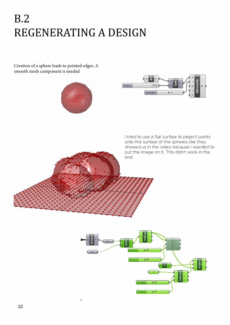
Creation of a sphere leads to pointed edges. A smooth mesh component is needed
I tried to use a flat surface to project points onto the surface of the sphere’s like they showed us in the video because i wasnted to put the image on it. This didn’t work in the end.

23
Even though i copied and pasted this algorithim from the Museum video which we watched this week, it would not work with my surface. The expressions were incorrect and as i didn’t understand why they were incorrect i couldn’t resolve the issue. At most i would get cirlcles or arcs at horizontal planes. I
wanted verticle planes which wrapped around the object. As the shape was extreemly complex i couldn’t unroll it Therefore neither could i place the pattern on the surface that way.
24
B.5THE TRAVELLING SALESMAN
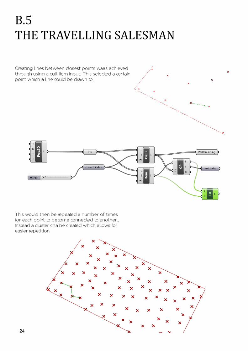
Creating lines between closest points waas achieved through using a cull item input. This selected a certain point which a line could be drawn to.
This would then be repeated a number of times for each point to become connected to another., Instead a cluster cna be created which allows for easier repetition.

25
I downloaded python and attempted to use it to script my own algorithm, however i was unsuc-cessful in creating anything.
26
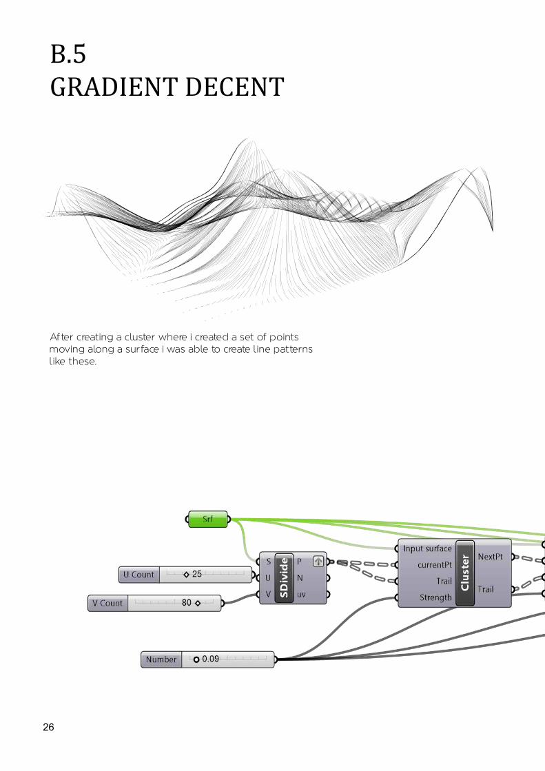
B.5GRADIENT DECENT
After creating a cluster where i created a set of points moving along a surface i was able to create line patterns like these.
27
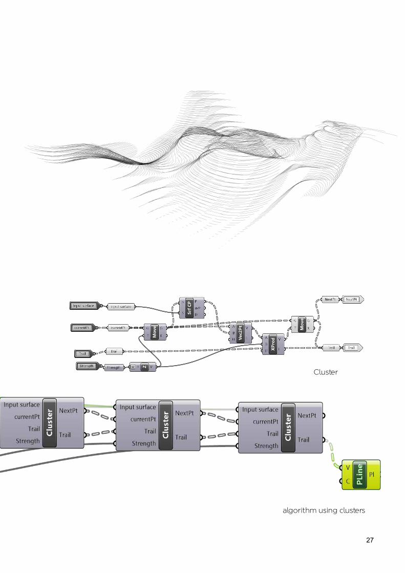
Cluster
algorithm using clusters

28
B.5FRACTAL PATTERNS
Creating clusters i was able to rotate and scale two curves around one another. I tried this inputing both curved and straight lines. I then tried to input a closed shape (the polygon) to achieve somewhat successful results.

29
This was then applied to a closed curve which was moved upwards.
Next, using a 3D box with curves intersecting it, i was able to create a cluster which formed boxes around those curves.. this created an interesting structre.

30
B.5KANGAROO- Plug-In
Kangaroo allows movement of shapes created in grasshopper in relation to toggle and stress/rest sliders.
9.5 rest length
Returning the rest length to 10 does not mean that the line will take the same form as previously
Applying a gravity component onto a line will make it catenery form. When i applied a negative charge a floating line was created.
31
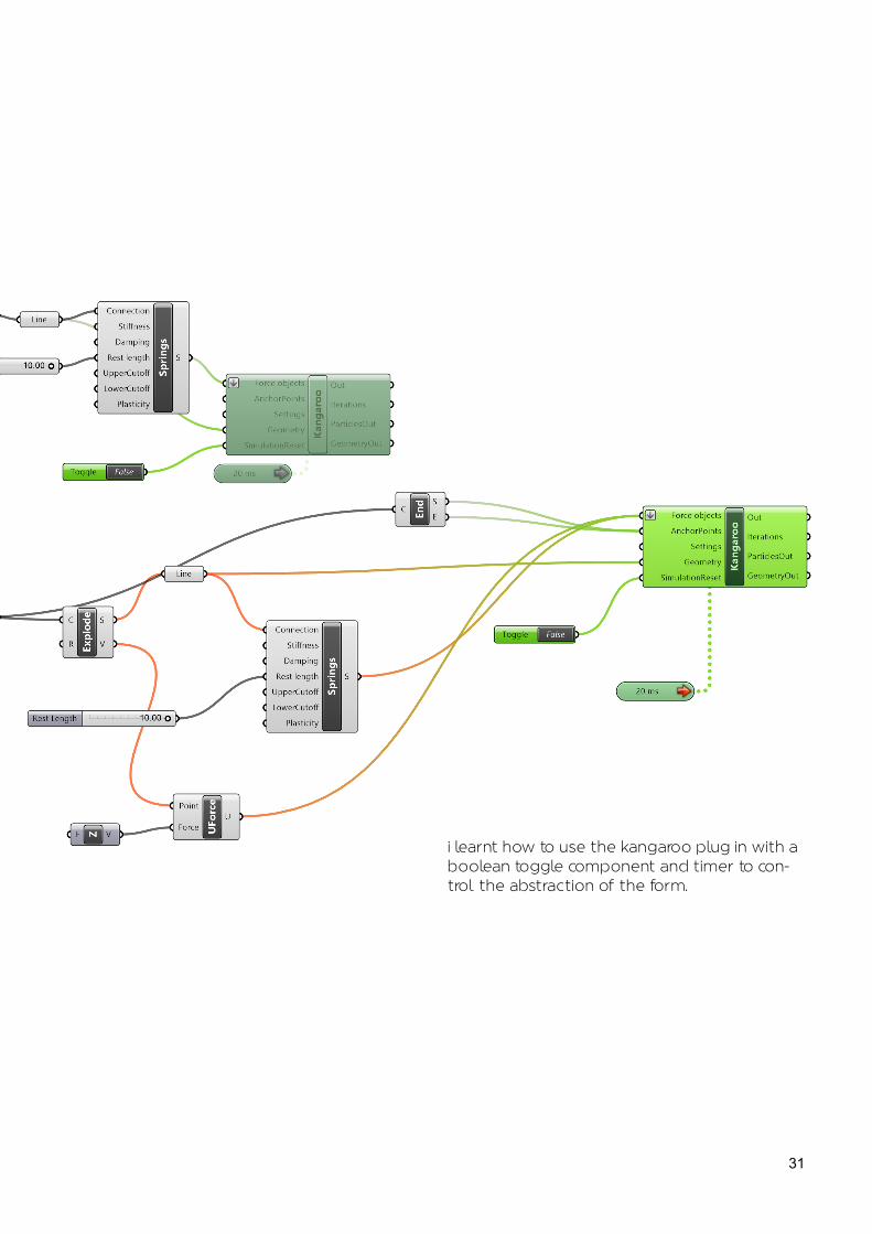
i learnt how to use the kangaroo plug in with a boolean toggle component and timer to con-trol the abstraction of the form.

32
B.5KANGAROO & Weavebird- Plug-Ins
These plug-ins allowed me to turn a edged structure into a more organic form.
original form
form after kangaroo

33
I was able to simulate this on to my own three-D meshed shape.
5 second deformation
11 second deformation

34
B.5Voussior CloudKANGAROO & Weavebird- Plug-Ins
base shape created through a combination of Rhino (points and base shape) and grashopper (vorrinoi shape contained within).
The pattern was scalled and set down by a certain z factor.
Through lofting a basic form was created. When i imported this into kangaroo i was able to play with the form, using the Naked points as ancor points.
35
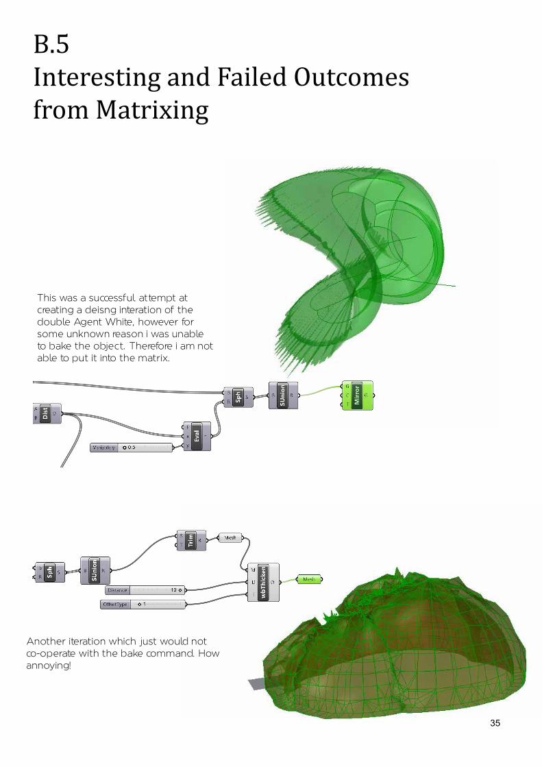
B.5Interesting and Failed Outcomes from Matrixing
This was a successful attempt at creating a deisng interation of the double Agent White, however for some unknown reason i was unable to bake the object. Therefore i am not able to put it into the matrix.
Another iteration which just would not co-operate with the bake command. How annoying!

36
This is a really cool des-ing. I don't have any idea of how i did it, but im glad that i did. It seems as if there is a central point where all of the fans are rotating outwards from.
B.5MATRIX DESIGNS

37
From the Sphere shape i was able to project the vorrinoi onto a flat surface. Whist i don't see much potential for this in regards to the breif, i think it a really cool design!

38
contours were created using a attractor point. Something i accidentily learnt how to do.

39
B.5DIGITAL PROTOTYPING
I helped to further explore the contouring iteration which was explored in the matrix and explained on pp 72 of my journal. It is seen on pp 36 of my Sketchook.
We used one of the video's to create surface contours running in the opposite direction to the inital iteration. I think that this creates a more sculptural and practicle form than what was initially created.
40

41
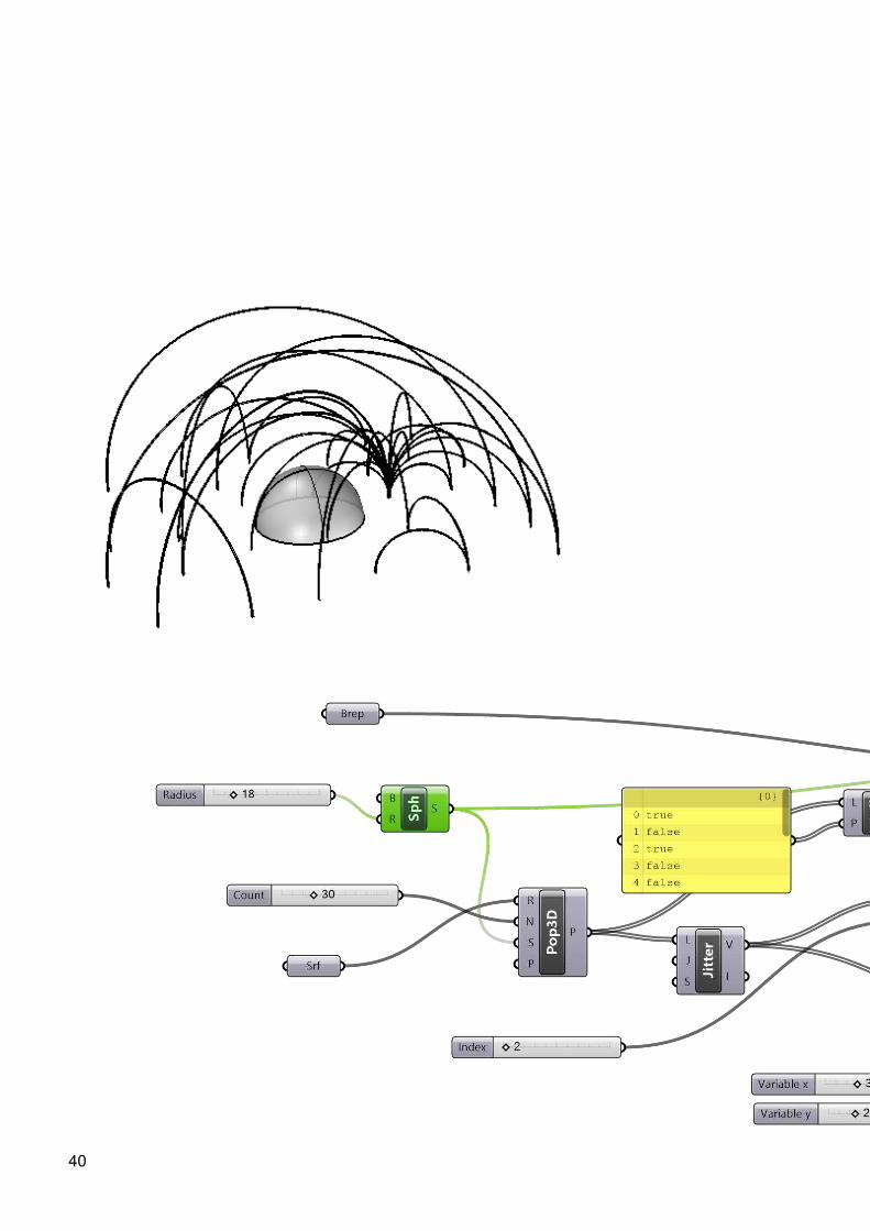
i was responsible for the digital prototype #2. I aimed to recreate and further explore the physical prototype which i made (see Journal page 78). I found it to be a difficult process as i knew what i wanted the model to look like, however i had trouble trplicating it in Rhino. After some time, however, i achieved a model which i believe closely represented whiat i was trying to achieve. It created an elegant design of randomly sized and placed arcs on the site over the sphere like shape.

42
B.5DIGITAL TO PHYSICAL PROTOTYPING
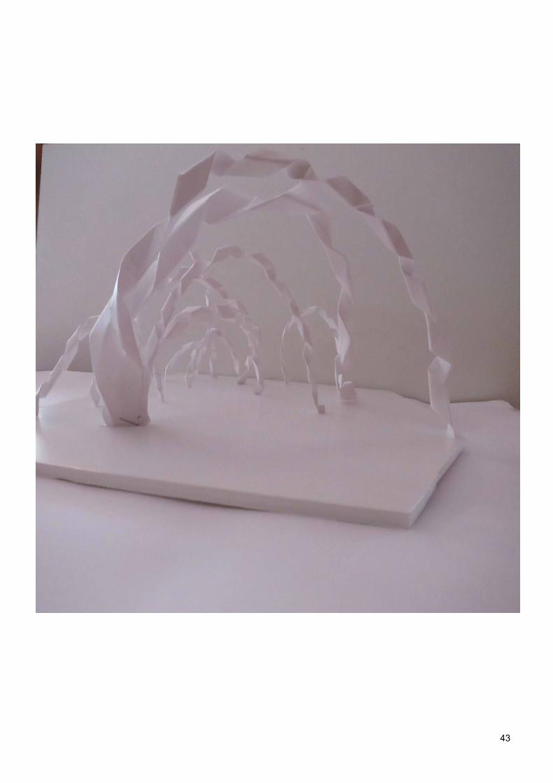
I attempted to re-create my piped arcs by had to test them in a real life situa-tion. Straight away issues were run into with the creation of the pipe. It was not a smooth curve, as grasshopper had modelled, rather the paper bended at odd angles creating a pointed form. In order to create a smoother curve differ-ent folds and papers were experimented with.
This twisted form created by folding the paper around itself was the best suited as it curved but still maintained a pipe-like form. This al-lowed the structural form to be replicated to a certain extent.
43