· PDF filecodec alc 888s 8ch or 6ch, ... cha_fan_pwr. gnd cpu fan pwr cpu fan in cpu fan pwm....
8
AP480-S Motherboard layout reference Contents • Specifications summary • Motherboard layout • Rear panel connectors • Function selectors • Internal connectors JUL 2008
Transcript of · PDF filecodec alc 888s 8ch or 6ch, ... cha_fan_pwr. gnd cpu fan pwr cpu fan in cpu fan pwm....
AP480-SMotherboard layout reference
Contents
• Specifications summary• Motherboard layout• Rear panel connectors• Function selectors• Internal connectors
JUL 2008
�AP480-S motherboard layout reference
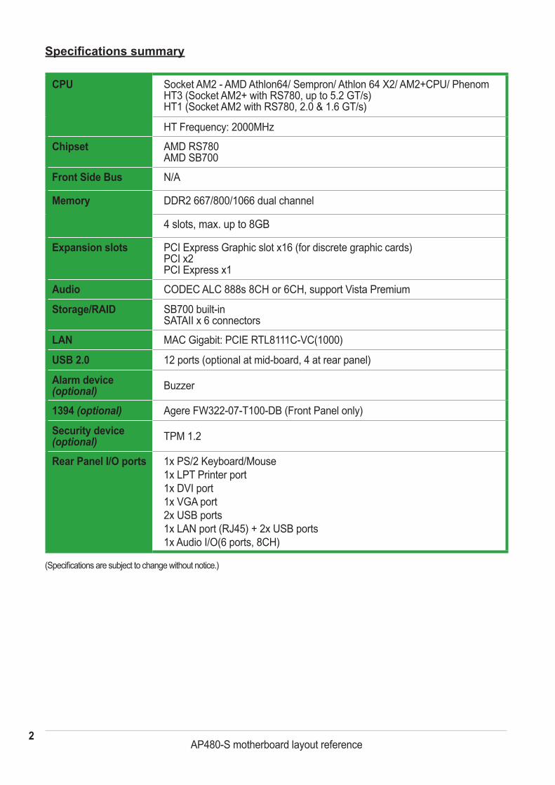
Specifications summary
(Specifications are subject to change without notice.)
CPU Socket AM2 - AMD Athlon64/ Sempron/ Athlon 64 X2/ AM2+CPU/ Phenom HT3 (Socket AM2+ with RS780, up to 5.2 GT/s) HT1 (Socket AM2 with RS780, 2.0 & 1.6 GT/s)
HT Frequency: 2000MHz
Chipset AMD RS780 AMD SB700
Front Side Bus N/A
Memory DDR2 667/800/1066 dual channel
4 slots, max. up to 8GB
Expansion slots PCI Express Graphic slot x16 (for discrete graphic cards) PCI x2 PCI Express x1
Audio CODEC ALC 888s 8CH or 6CH, support Vista Premium
Storage/RAID SB700 built-in SATAII x 6 connectors
LAN MAC Gigabit: PCIE RTL8111C-VC(1000)
USB �.0 12 ports (optional at mid-board, 4 at rear panel)
Alarm device (optional) Buzzer
1394 (optional) Agere FW322-07-T100-DB (Front Panel only)
Security device (optional) TPM 1.2
Rear Panel I/O ports 1x PS/2 Keyboard/Mouse 1x LPT Printer port 1x DVI port 1x VGA port 2x USB ports 1x LAN port (RJ45) + 2x USB ports 1x Audio I/O(6 ports, 8CH)
3AP480-S motherboard layout reference
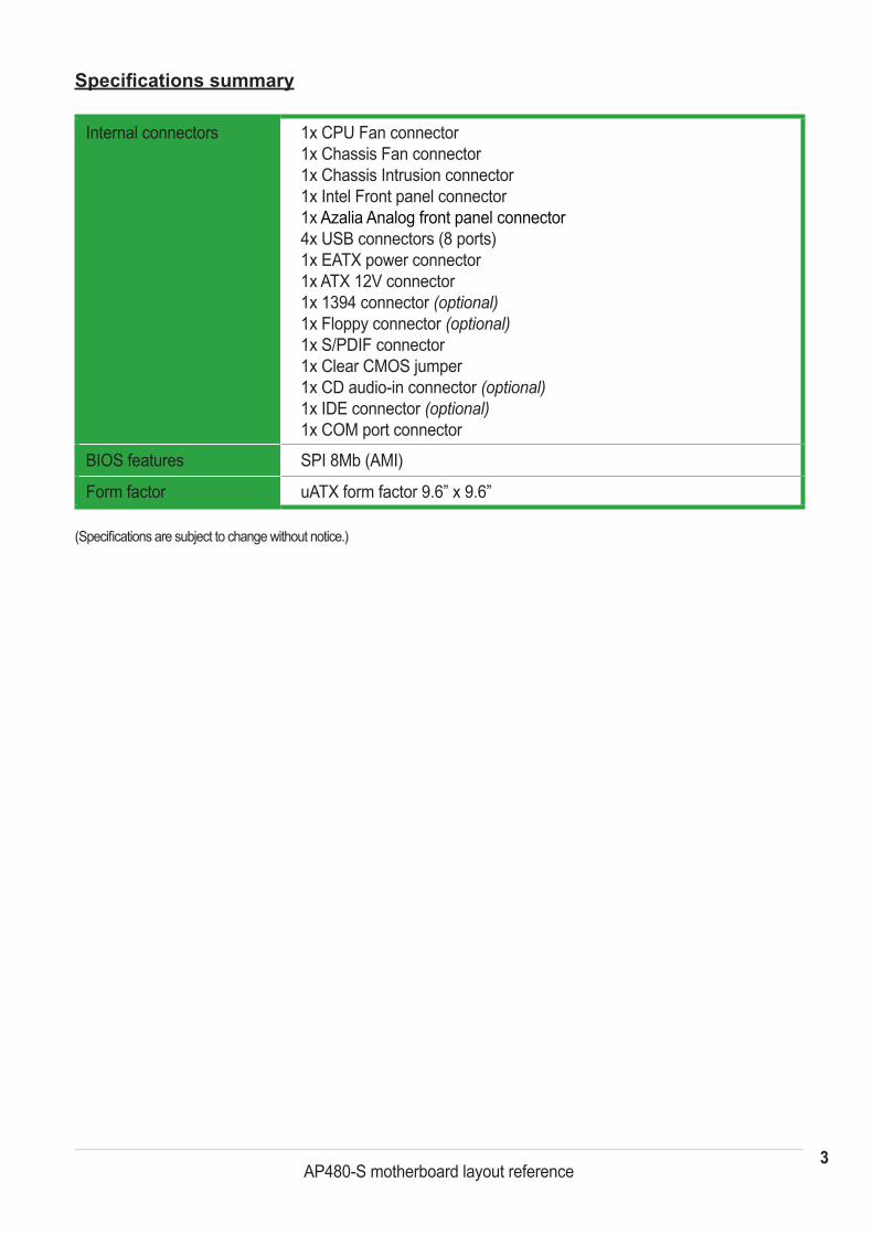
Specifications summary
Internal connectors 1x CPU Fan connector 1x Chassis Fan connector 1x Chassis Intrusion connector 1x Intel Front panel connector 1x Azalia Analog front panel connector 4x USB connectors (8 ports) 1x EATX power connector 1x ATX 12V connector 1x 1394 connector (optional) 1x Floppy connector (optional) 1x S/PDIF connector 1x Clear CMOS jumper 1x CD audio-in connector (optional) 1x IDE connector (optional) 1x COM port connector
BIOS features SPI 8Mb (AMI)
Form factor uATX form factor 9.6” x 9.6”
(Specifications are subject to change without notice.)
4AP480-S motherboard layout reference
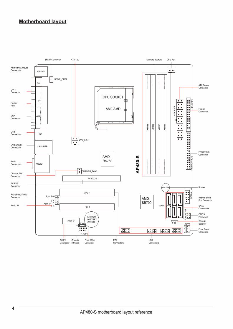
Motherboard layout
KB · MS
SPDIF_OUT2
CHASSIS_FAN1
XM
M1
XM
M2
XM
M3
XM
M4
ATX
PW
R
PR
IMA
RY
IDE
SATA
CM
OS
PW
F_
PAN
EL P 12
ATX_CPU
AUX_IN
F_AUDIO PCI 2
PCIE X16
PCI 1
DVI
LPT
VGA
LAN · USB
AUDIO
USB
PCIConnectors
PCIE1Connector
ChassisIntrusion
PCIE X1
USBConnectors
Memory Sockets
CPU Fan ATX 12V SPDIF Connector
AMDRS780
AMDSB700
BUZZERS
ER
IAL_
A
AP
480-
S
Keyboard & MouseConnectors
PrinterPort
VGAConnector
DVI-IConnector
LAN & USBConnectors
USBConnectors
AudioConnectors
PCIE16Connector
Chassis FanConnector
Front Panel AudioConnector
Audio IN
CPU SOCKET
AM2-AMD
LITHIUMBATTERYCR2032
CMOSPassword
Front PanelConnector
ChassisSpeaker
SATAConnectors
Buzzer
Primary IDEConnector
ATX PowerConnector
Internal SerialPort Connector
FloppyConnector
FLO
PP
Y
Front 1394Connector
F_1394
P 305
�AP480-S motherboard layout reference
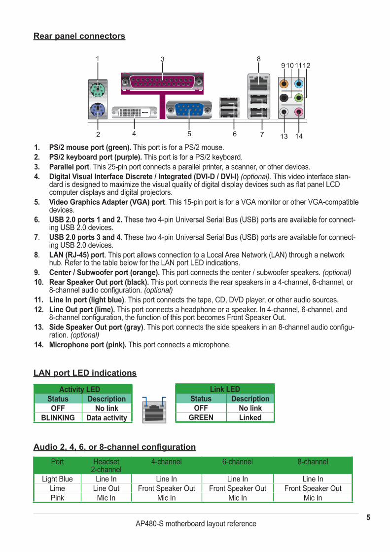
Rear panel connectors
Audio 2, 4, 6, or 8-channel configuration
1. PS/2 mouse port (green). This port is for a PS/2 mouse.�. PS/2 keyboard port (purple). This port is for a PS/2 keyboard.3. Parallel port. This 25-pin port connects a parallel printer, a scanner, or other devices.4. Digital Visual Interface Discrete / Integrated (DVI-D / DVI-I) (optional). This video interface stan-
dard is designed to maximize the visual quality of digital display devices such as flat panel LCD computer displays and digital projectors.
5. Video Graphics Adapter (VGA) port. This 15-pin port is for a VGA monitor or other VGA-compatible devices.
6. USB �.0 ports 1 and �. These two 4-pin Universal Serial Bus (USB) ports are available for connect-ing USB 2.0 devices.
7. USB �.0 ports 3 and 4. These two 4-pin Universal Serial Bus (USB) ports are available for connect-ing USB 2.0 devices.
8. LAN (RJ-45) port. This port allows connection to a Local Area Network (LAN) through a network hub. Refer to the table below for the LAN port LED indications.
9. Center / Subwoofer port (orange). This port connects the center / subwoofer speakers. (optional)10. Rear Speaker Out port (black). This port connects the rear speakers in a 4-channel, 6-channel, or
8-channel audio configuration. (optional)11. Line In port (light blue). This port connects the tape, CD, DVD player, or other audio sources. 12. Line Out port (lime). This port connects a headphone or a speaker. In 4-channel, 6-channel, and
8-channel configuration, the function of this port becomes Front Speaker Out.13. Side Speaker Out port (gray). This port connects the side speakers in an 8-channel audio configu-
ration. (optional)14. Microphone port (pink). This port connects a microphone.
1 3
6 72 4 5
89101112
13 14
Port Headset2-channel
4-channel 6-channel 8-channel
Light Blue Line In Line In Line In Line InLime Line Out Front Speaker Out Front Speaker Out Front Speaker OutPink Mic In Mic In Mic In Mic In
LAN port LED indications
Activity LEDStatus DescriptionOFF No link
BLINKING Data activity
Link LEDStatus DescriptionOFF No link
GREEN Linked
6AP480-S motherboard layout reference
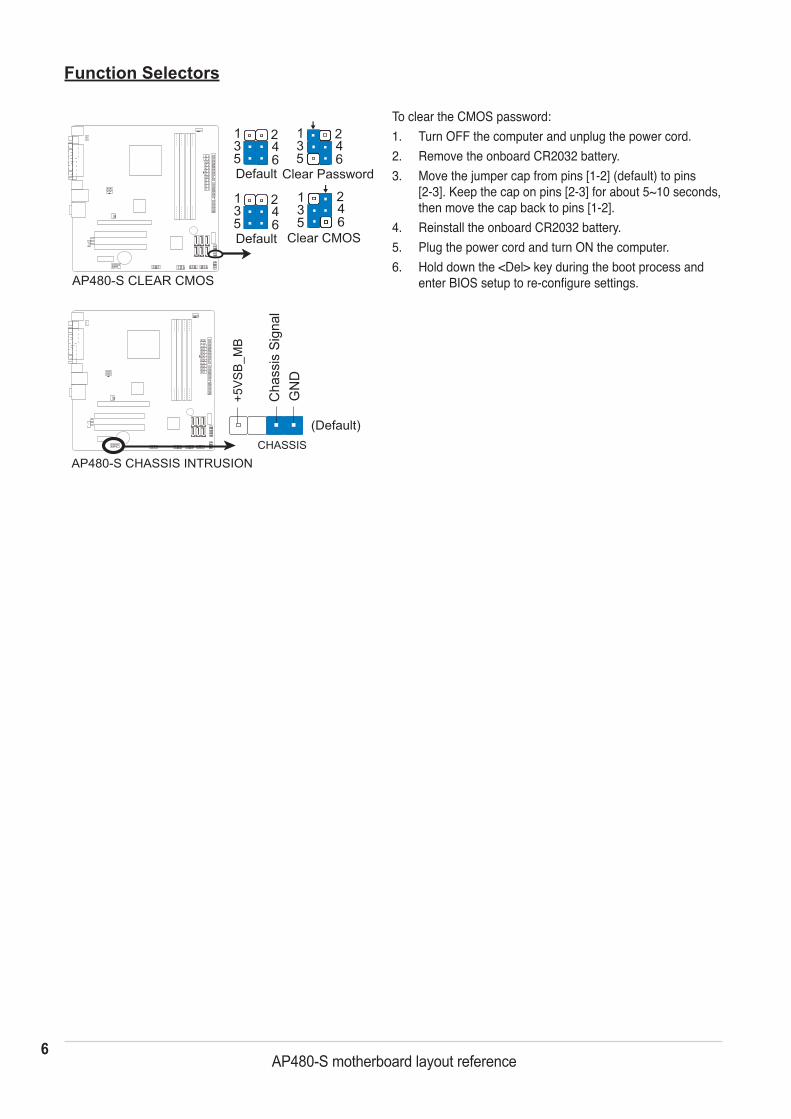
Function Selectors
Default Clear CMOS
Clear Password
AP480-S CLEAR CMOS
135
135
135
246
246
246
Default
135
246
AP480-S CHASSIS INTRUSIONCHASSIS
+5VS
B_M
B
Cha
ssis
Sig
nal
GN
D
(Default)
To clear the CMOS password:1. Turn OFF the computer and unplug the power cord.2. Remove the onboard CR2032 battery.3. Move the jumper cap from pins [1-2] (default) to pins
[2-3]. Keep the cap on pins [2-3] for about 5~10 seconds, then move the cap back to pins [1-2].
4. Reinstall the onboard CR2032 battery.5. Plug the power cord and turn ON the computer.6. Hold down the <Del> key during the boot process and
enter BIOS setup to re-configure settings.
�AP480-S motherboard layout reference
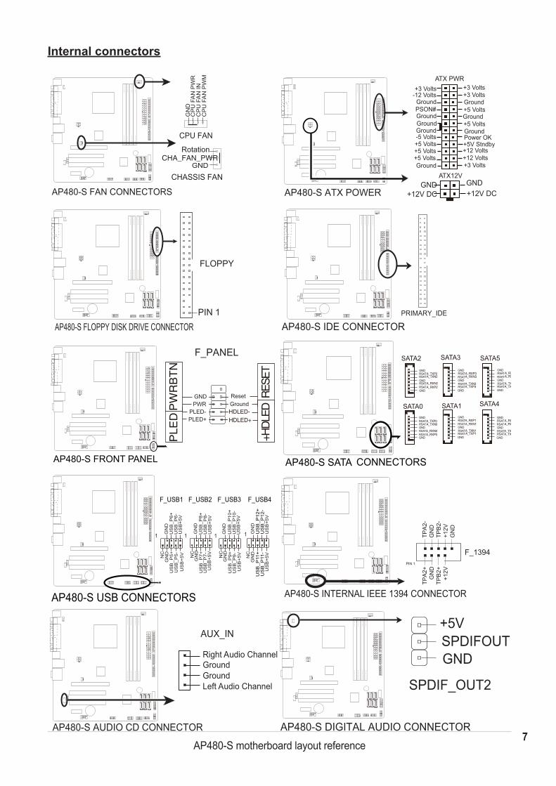
+12V DCGND GND
+12V DC
ATX12V
ATX PWR+3 Volts
Ground
Ground
Ground
Ground
GroundPSON#
+5 Volts
+5 Volts-5 Volts
+5 Volts
-12 Volts+3 Volts+3 Volts
+3 Volts
+5V StndbyPower OK
Ground
Ground
Ground+5 Volts
+5 Volts
+12 Volts+12 Volts
AP480-S ATX POWER
Internal connectors
AP480-S FAN CONNECTORS
GND
RotationCHA_FAN_PWR
GN
DC
PU
FA
N P
WR
CP
U F
AN
INC
PU
FA
N P
WM
CPU FAN
CHASSIS FAN
Right Audio Channel
Left Audio ChannelGroundGround
AP480-S AUDIO CD CONNECTOR
AUX_IN
GNDRSATRSATGNDRSATRSATGND
GNDRSATA_TXP3RSATA_TXN3GNDRSAT
A_RXP3RSATA_RXN3
GND
SATA3
SATA1
SATA5
SATA4
GND
GND
GND
GND
ATRS A_TXP2
RSATA_TXP0
A_TXP1A_TXN1
RSATA_TXN2
RSATA_TXN0
GND
A_RXP2
RSATA_RXP0
A_RXP1
RSATRSATA_RXN2
RSATA_RXN0
A_RXN1
GND
SATA2
SATA0
GNDRSATA_TXP5RSATA_TXN5GNDRSAT
A_RXP5RSATA_RXN5
GND
GNDRSATA_TXP4RSATA_TXN4GNDRSAT
A_RXP4RSATA_RXN4
GND
AP480-S SATA CONNECTORS
+5VSPDIFOUTGND
AP480-S DIGITAL AUDIO CONNECTOR
SPDIF_OUT2
AP480-S INTERNAL IEEE 1394 CONNECTOR
PIN 1
TPA
2-G
ND
TPB
2-+1
2VG
ND
TPA
2+G
ND
TPB
2++1
2V
F_1394
PIN 1
FLOPPY
AP480-S FLOPPY DISK DRIVE CONNECTOR
F_PANEL
GroundReset
HDLED+HDLED-
+HDLE
DRES
ET
GNDPWR
PLED-PLED+
PLE
D
AP480-S FRONT PANEL
PW
RB
TN
AP480-S IDE CONNECTORPRIMARY_IDE
AP480-S USB CONNECTORS
F_USB1 F_USB2 F_USB3 F_USB4
US
B+5
VU
SB
_P6-
US
B_P
6+G
ND
NC
US
B+5
V
GN
D
1
US
B_P
5-U
SB
_P5+
US
B+5
VU
SB
_P8-
US
B_P
8+G
ND
NC
US
B+5
V
GN
D
1
US
B_P
7-U
SB
_P7+
1
US
B+5
VU
SB
_P10
-U
SB
_P10
+G
ND
NC
US
B+5
V
GN
D
US
B_P
9-U
SB
_P9+
US
B+5
V
GN
DN
C
US
B+5
V
GN
D
1
US
B_P
11-
US
B_P
11+
US
B_P
12-
US
B_P
12+
8AP480-S motherboard layout reference
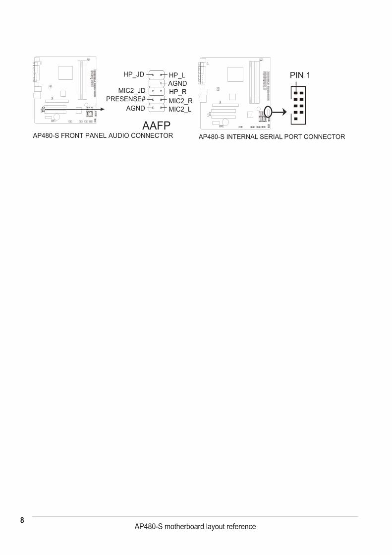
AAFP
HP_LAGNDHP_RMIC2_RMIC2_L
HP_JD
MIC2_JDPRESENSE#
AGND
AP480-S FRONT PANEL AUDIO CONNECTOR
PIN 1
AP480-S INTERNAL SERIAL PORT CONNECTOR