Albany Medical Center - Pennsylvania State University · Virtual Work: External Work = Internal...
27
Albany Medical Center Patient Pavilion Albany, Ny Thomas J. Kleinosky – Structural Senior Thesis 2012| Advisor: Dr. Hanagan
Transcript of Albany Medical Center - Pennsylvania State University · Virtual Work: External Work = Internal...

Albany Medical Center
Patient Pavilion
Albany, Ny
Thomas J. Kleinosky – Structural Senior Thesis 2012| Advisor: Dr. Hanagan

PROJECT OUTLINE Project Phasing
Phase 1: Existing Design
348,000 square feet
6 stories above grade plus subbasement
227,000 square foot expansion
4 additional stories
Mechanical penthouse added
Building Introduction
Existing Structure
Thesis Proposal
Progressive Collapse
MAE Incorporation
Mechanical Breadth
Conclusion
Phase 2: Vertical Expansion
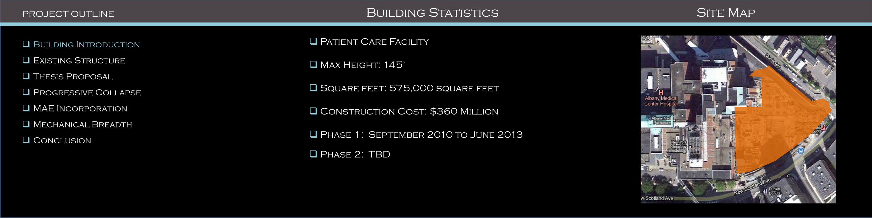
Patient Care Facility
Max Height: 145’
Square feet: 575,000 square feet
Construction Cost: $360 Million
Phase 1: September 2010 to June 2013
Phase 2: TBD
PROJECT OUTLINE Building Statistics Site Map
Building Introduction
Existing Structure
Thesis Proposal
Progressive Collapse
MAE Incorporation
Mechanical Breadth
Conclusion

• Owner: Albany Medical Center
• Architect: TRO Jung|Brannen
• General Contractor: Gilbane Building Co.
• Structural Engineer: Ryan-Biggs Associates
• Mechanical Engineer: ICOR Associates
• Civil Engineers: Clark Patterson Lee
PROJECT OUTLINE Building Statistics
Building Introduction
Existing Structure
Thesis Proposal
Progressive Collapse
MAE Incorporation
Mechanical Breadth
Conclusion
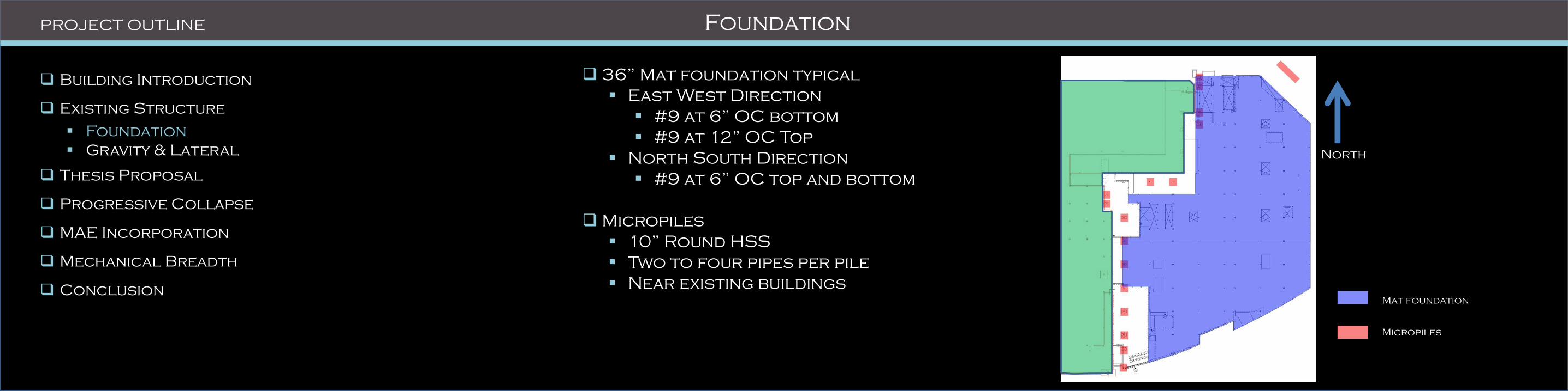
36” Mat foundation typical
East West Direction
#9 at 6” OC bottom
#9 at 12” OC Top
North South Direction
#9 at 6” OC top and bottom
Micropiles
10” Round HSS
Two to four pipes per pile
Near existing buildings
PROJECT OUTLINE Foundation
Mat foundation
Micropiles
Building Introduction
Existing Structure
Foundation
Gravity & Lateral
Thesis Proposal
Progressive Collapse
MAE Incorporation
Mechanical Breadth
Conclusion
North

PROJECT OUTLINE Foundation
Building Introduction
Existing Structure
Foundation
Gravity & Lateral
Thesis Proposal
Progressive Collapse
MAE Incorporation
Mechanical Breadth
Conclusion Mat foundation
Micropiles
PROJECT OUTLINE Framing System
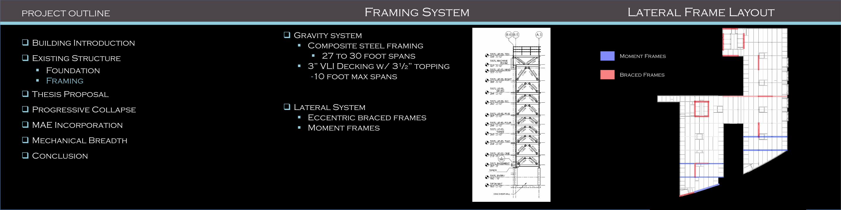
Moment Frames
Braced Frames
Gravity system
Composite steel framing
27 to 30 foot spans
3” VLI Decking w/ 3½” topping
-10 foot max spans
Lateral System
Eccentric braced frames
Moment frames
Building Introduction
Existing Structure
Foundation
Framing
Thesis Proposal
Progressive Collapse
MAE Incorporation
Mechanical Breadth
Conclusion
Lateral Frame Layout

Structural Depth (per UFC 04-023-03):
Progressive Collapse Analysis:
Alternate Path Method (direct method)
Tie-Force Method (indirect method)
PROJECT OUTLINE Problem Statement
Building Introduction
Existing Structure
Thesis Proposal
Progressive Collapse
MAE Incorporation
Mechanical Breadth
Conclusion
Mechanical Breadth:
Façade Redesign:
Analyze Thermal Performance
Cost comparison
Construction Management Breadth:
Site Logistics:
Develop site logistics for precast facade
Develop site logistics for existing building
MAE Course Related Study:
AE 534: Design of Steel Connection
Extended Shear Tab Connection
Welded Unreinforced Flange Moment
Connection
PROJECT OUTLINE
Building Introduction
Existing Structure
Thesis Proposal
Progressive Collapse
Tie-Force Method
Preliminary Member Sizes
Alternate Path Method
MAE Incorporation
Mechanical Breadth
Conclusion
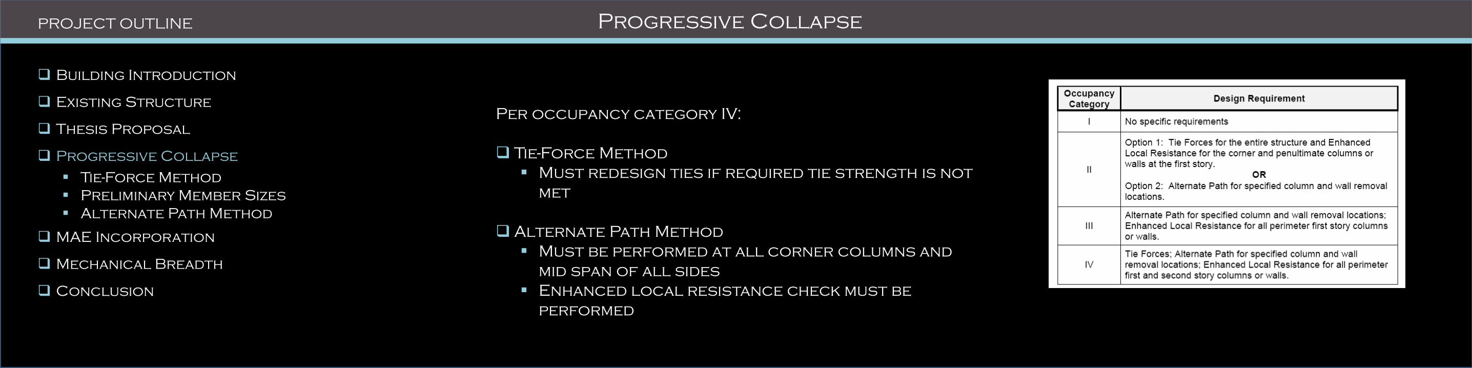
Progressive Collapse
Per occupancy category IV:
Tie-Force Method
Must redesign ties if required tie strength is not
met
Alternate Path Method
Must be performed at all corner columns and
mid span of all sides
Enhanced local resistance check must be
performed

PROJECT OUTLINE
Building Introduction
Existing Structure
Thesis Proposal
Progressive Collapse
Tie-Force Method
Preliminary Member Sizes
Alternate Path Method
MAE Incorporation
Mechanical Breadth
Conclusion
Indirect Method
Requires ductility, continuity, and redundancy
Mechanically “ties” the building together
Tie placement
Restrictions
Tie-Forces Method

Longitudinal and Transverse Reinforcement:
Required tie strength (lb/ft):
𝐹𝑖 = 3𝑤𝐹𝐿1
𝑤𝑓 = 1.2𝐷 + 0.5𝐿
𝐿1 = greatest bay length
Reinforcement Design:
𝐴𝑚𝑖𝑛 = 𝐹𝑖
∅ ∙ Ω ∙ 𝐹𝑦
PROJECT OUTLINE Longitudinal and Transverse Ties
Building Introduction
Existing Structure
Thesis Proposal
Progressive Collapse
Tie-Force Method
Preliminary Member Sizes
Alternate Path Method
MAE Incorporation
Mechanical Breadth
Conclusion

Results/Conclusion
No. 4 bars used (TYP.)
Typical spacing 10-12 inches
PROJECT OUTLINE Longitudinal and Transverse Ties
Building Introduction
Existing Structure
Thesis Proposal
Progressive Collapse
Tie-Force Method
Preliminary Member Sizes
Alternate Path Method
MAE Incorporation
Mechanical Breadth
Conclusion
Longitudinal Transverse
Length (ft.) 30 27.33
Fi/F
P (kip/ft)/(kip) 14.8 13.5
As min
(in.2) 0.219 0.2
Bar Used No. 4 No. 4
Spacing (in.) 10 12
Max Spacing (in.) 65 72
Basement to 2nd Level - wf = 164 psf
Longitudinal Transverse
Length (ft.) 30 27.33
Fi/F
P (kip/ft)/(kip) 13.9 12.6
As min
(in.2) 0.205 0.187
Bar Used No. 4 No. 4
Spacing (in.) 11 12
Max Spacing (in.) 65 72
3rd to 8th Level - wf = 154 psf
Longitudinal Transverse
Length (ft.) 30 27.33
Fi/F
P (kip/ft)/(kip) 19.2 17.5
As min
(in.2) 0.284 0.259
Bar Used No. 4 No. 4
Spacing (in.) 8 9
Max Spacing (in.) 65 72
Penthouse Level - wf = 213 psf
Longitudinal Transverse
Length (ft.) 30 27.33
Fi/F
P (kip/ft)/(kip) 11.2 10.2
As min
(in.2) 0.166 0.151
Bar Used No. 4 No. 4
Spacing (in.) 14 15
Max Spacing (in.) 65 72
Roof Level - wf = 124 psf

Virtual Work:
External Work = Internal Work
External Work
Resulting point load
Internal Work
Work absorbed by the hinges
Product of the moment and the rotation
Small angle theory
sin 𝜃 = tan 𝜃 = 𝜃(𝑟𝑎𝑑𝑖𝑎𝑛𝑠)
PROJECT OUTLINE Preliminary Member Sizes
Building Introduction
Existing Structure
Thesis Proposal
Progressive Collapse
Tie-Force Method
Preliminary Member Sizes
Alternate Path Method
MAE Incorporation
Mechanical Breadth
Conclusion

Description:
Direct Method
Bridge over removed elements
Column Removal requirements
Exterior frames modeled as moment frames
PROJECT OUTLINE Alternate Path Method
Building Introduction
Existing Structure
Thesis Proposal
Progressive Collapse
Tie-Force Method
Preliminary Member Sizes
Alternate Path Method
MAE Incorporation
Mechanical Breadth
Conclusion
Removed Column
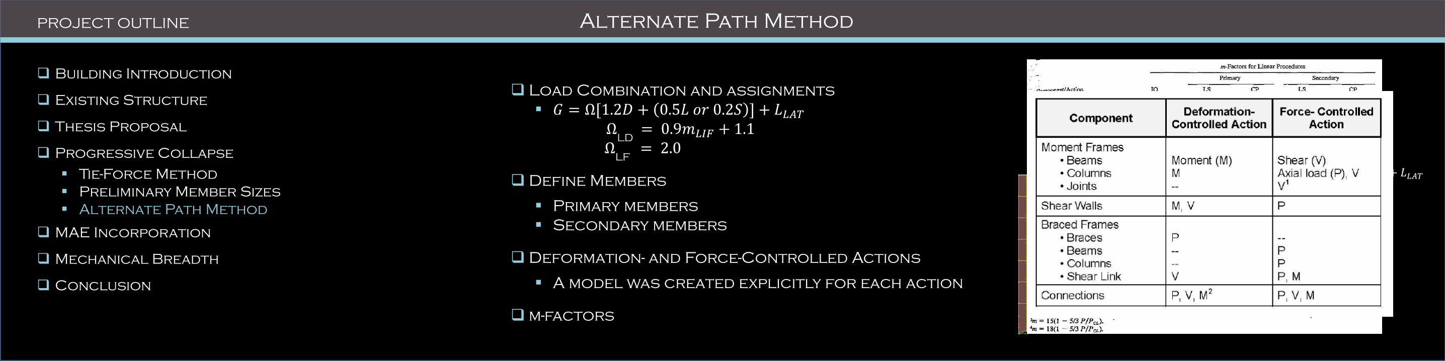
Load Combination and assignments
𝐺 = Ω[1.2𝐷 + 0.5𝐿 𝑜𝑟 0.2𝑆 ] + 𝐿𝐿𝐴𝑇
ΩLD
= 0.9𝑚𝐿𝐼𝐹 + 1.1
Ω
LF = 2.0
Define Members
Primary members
Secondary members
Deformation- and Force-Controlled Actions
A model was created explicitly for each action
m-factors
PROJECT OUTLINE Alternate Path Method
Building Introduction
Existing Structure
Thesis Proposal
Progressive Collapse
Tie-Force Method
Preliminary Member Sizes
Alternate Path Method
MAE Incorporation
Mechanical Breadth
Conclusion
Removed Column
Ω[1.2𝐷 + 0.5𝐿 𝑜𝑟 0.2𝑆 ] + 𝐿𝐿𝐴𝑇
1.2𝐷 + 1.6𝐿 + 0.2𝑆

Beam Analysis
Calculate m-factors
Interaction equation (AISC Chapter H)
𝑃𝑟
2𝑃𝑐+
𝑀𝑟𝑥𝑀𝑐𝑥
+𝑀𝑟𝑦
𝑀𝑐𝑦
𝑚 𝑓𝑎𝑐𝑡𝑜𝑟 ≤ 1.0
Results
PROJECT OUTLINE Alternate Path Method
Building Introduction
Existing Structure
Thesis Proposal
Progressive Collapse
Tie-Force Method
Preliminary Member Sizes
Alternate Path Method
MAE Incorporation
Mechanical Breadth
Conclusion
Removed Column
Member Location Member Mr Pr Mc Pc m-factor Interaction
Roof W21X50 268.6 0 412.5 661.5 6 0.108525 PASS
Basement to 8th W24X62 1582.4 0 573.75 819 6 0.459666 PASS
Penthouse W24X76 1347.1 0 750 1008 6 0.299356 PASS
Member Location Member Mr Pr Mc Pc m-factor Interaction
Roof W21X50 302.7 0 412.5 661.5 6 0.12230303 PASS
Basement to 8th W24X62 1284.1 0 573.75 819 6 0.373013798 PASS
Penthouse W24X76 1481.6 0 750 1008 6 0.329244444 PASS
Member Location Member Mr Pr Mc Pc m-factor Interaction
Roof W21X50 916.4 0 412.5 661.5 6 0.370262626 PASS
Basement to 8th W24X62 85.4 0 573.75 819 6 0.024807553 PASS
Penthouse W24X76 109.3 0 750 1008 6 0.024288889 PASS
Results
Member Properties W21x50 W24x76 W24x62
bf/2tf 6.1 6.61 5.97
h/tw 49.4 49.00 50.10
52/√Fye 7.0117 7.0117 7.0117
418/√Fye 53.36 53.36 53.36
65/√Fye 8.76 8.76 8.76
640/√Fye 86.30 86.30 86.30
Beam m-factor 6.00 6.00 6.00
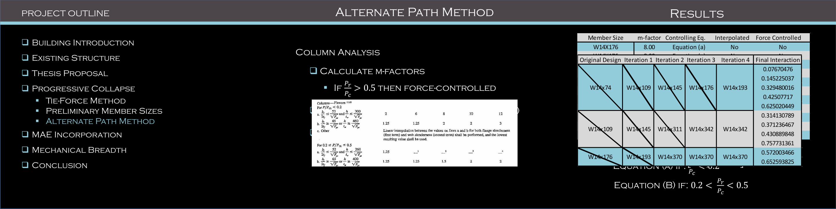
Column Analysis
Calculate m-factors
If 𝑃𝑟
𝑃𝑐> 0.5 then force-controlled
Interaction equations (AISC Chapter H)
Results
PROJECT OUTLINE Alternate Path Method
Building Introduction
Existing Structure
Thesis Proposal
Progressive Collapse
Tie-Force Method
Preliminary Member Sizes
Alternate Path Method
MAE Incorporation
Mechanical Breadth
Conclusion
Removed Column
Results
𝑃𝑟
2𝑃𝑐+
𝑀𝑟𝑥𝑀𝑐𝑥
+𝑀𝑟𝑦
𝑀𝑐𝑦
𝑚 𝑓𝑎𝑐𝑡𝑜𝑟 ≤ 1.0
When 𝑃𝑟
𝑃𝑐 ≤0.2
𝑃𝑟
𝑃𝑐+
8
9
𝑀𝑟𝑥𝑀𝑐𝑥
+𝑀𝑟𝑦
𝑀𝑐𝑦
𝑚 𝑓𝑎𝑐𝑡𝑜𝑟 ≤ 1.0
When 𝑃𝑟
𝑃𝑐 >0.2
Member Size m-factor Controlling Eq. Interpolated Force Controlled
W14X176 8.00 Equation (a) No No
W14X176 8.00 Equation (a) No No
W14X176 6.39 Equation (b) Yes No
W14X176 5.01 Equation (b) Yes No
W14X176 2.03 Equation (b) Yes No
W14X342 6.44 Equation (b) Yes No
W14X342 5.32 Equation (b) Yes No
W14X342 4.42 Equation (b) Yes No
W14X342 1.00 Equation (b) No Yes
W14X370 2.59 Equation (b) Yes No
W14X370 1.00 Equation (b) No Yes
Equation (a) if: 𝑃𝑟
𝑃𝑐< 0.2
Equation (B) if: 0.2 < 𝑃𝑟
𝑃𝑐< 0.5
Original Design Iteration 1 Iteration 2 Iteration 3 Iteration 4 Final Interaction
0.07670476
0.145225037
0.329480016
0.42507717
0.625020449
0.314130789
0.371236467
0.430889848
0.757731361
0.572003466
0.652593825W14x176 W14x193 W14x370 W14x370
W14x193
W14x342
W14x370
W14x74 W14x109 W14x145 W14x176
W14x109 W14x145 W14x311 W14x342
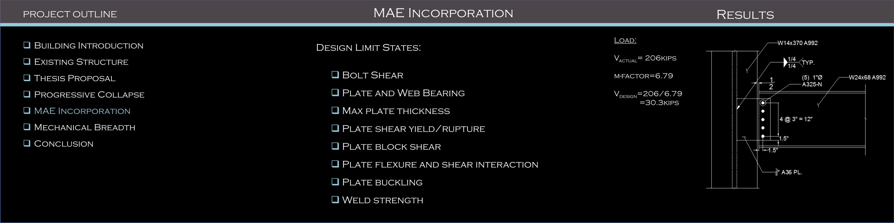
Design Limit States:
Bolt Shear
Plate and Web Bearing
Max plate thickness
Plate shear yield/rupture
Plate block shear
Plate flexure and shear interaction
Plate buckling
Weld strength
PROJECT OUTLINE MAE Incorporation
Building Introduction
Existing Structure
Thesis Proposal
Progressive Collapse
MAE Incorporation
Mechanical Breadth
Conclusion
Removed Column
Results
Load:
Vactual
= 206kips
m-factor=6.79
Vdesign
=206/6.79
=30.3kips

Building Introduction
Existing Structure
Thesis Proposal
Gravity System
Progressive Collapse
MAE Incorporation
Mechanical Breadth
Conclusion
Introduction:
Analyzing a typical patient room
Calculate thermal performance of existing
façade
Propose a new precast façade
Process:
Determine number of patient rooms on exterior
of building in each direction
Obtain pricing from precast and glass
manufacturer
Material cost analysis
Run a trace model
Energy cost analysis
PROJECT OUTLINE Mechanical Breadth

Building Introduction
Existing Structure
Thesis Proposal
Gravity System
Progressive Collapse
MAE Incorporation
Mechanical Breadth
Conclusion
Existing Wall Construction:
4” Vented Brick
1 ¾” Air Space
2” Rigid Insulation
Vapor Barrier
½” Plywood Sheathing
6” Cold Formed Metal Framing
5/8” Gypsum Wall Board
U-value=0.073
PROJECT OUTLINE Mechanical Breadth
Existing Glazing:
Viracon VE19-2M
U-value=0.25
S.C.=0.30
Proposed Precast Wall Construction:
½” face brick
3” concrete
3” rigid Polystyrene rigid board insulation
3” Concrete
U-Value=0.061
Proposed Glazing:
Oldcastle Buildingenvelope Low-e #2
U-value=0.24
S.C.=0.28
Existing Proposed Difference
Sq ft 58.67 58.67
# Rooms 242 242
Cost/sq ft 11.00$ 12.80$
Total Cost 156,179.54$ 181,736.19$ 25,556.65$
Glazing Cost Comparison
Existing Proposed Difference
Sq ft 105.33 105.33
# Rooms 242 242
Cost/sq ft 26.14$ 29.00$
Total Cost 666,304.94$ 739,205.94$ 72,901.00$
Façade Cost Comparison
Building Introduction
Existing Structure
Thesis Proposal
Gravity System
Progressive Collapse
MAE Incorporation
Mechanical Breadth
Conclusion
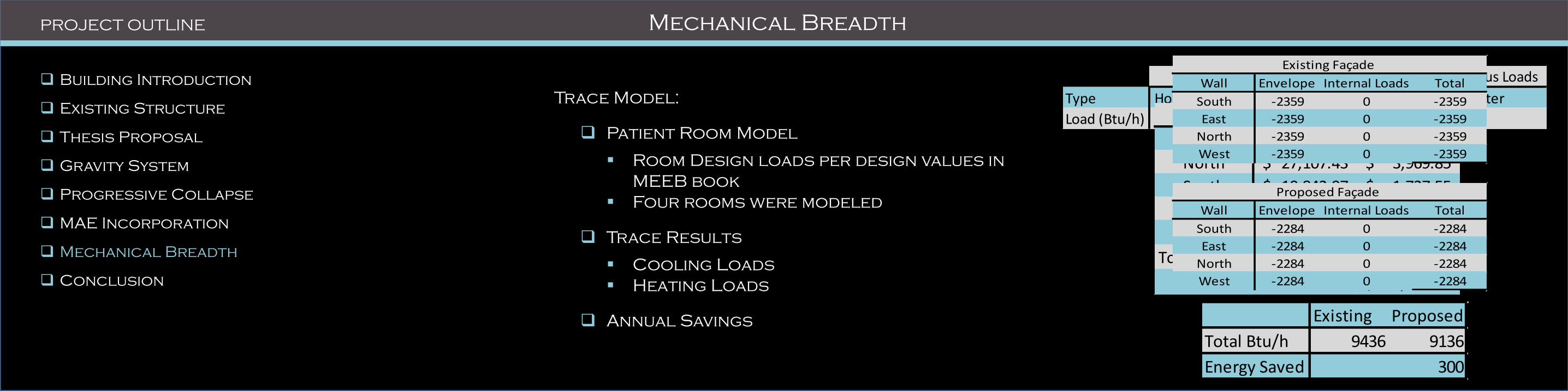
Trace Model:
Patient Room Model
Room Design loads per design values in
MEEB book
Four rooms were modeled
Trace Results
Cooling Loads
Heating Loads
Annual Savings
PROJECT OUTLINE Mechanical Breadth
People Lighting Miscellaneous Loads
Type Hospital Room Recessed Fluorescent Computer
Load (Btu/h) 400 900 80
Wall Envelope Internal Loads Total
South 2864 1438 9412
East 4090 1020 7212
North 1204 898 6474
West 3352 1020 4372
Proposed Façade
Wall Envelope Internal Loads Total
South 3636 1438 10934
East 4840 1020 8108
North 1350 898 7873
West 4605 1020 5625
Existing Façade
Wall Heating Cooling
North 27,107.43$ 3,969.85$
South 10,842.97$ 1,727.55$
East 78,912.75$ 7,401.56$
West 28,914.60$ 3,792.60$
Total Annual 145,777.75$ 16,891.56$
Total 162,669.32$
Energy Savings
Wall Envelope Internal Loads Total
South -2359 0 -2359
East -2359 0 -2359
North -2359 0 -2359
West -2359 0 -2359
Existing Façade
Wall Envelope Internal Loads Total
South -2284 0 -2284
East -2284 0 -2284
North -2284 0 -2284
West -2284 0 -2284
Proposed Façade
Existing Proposed
Total Btu/h 32540 27470
Energy Saved 5070
Existing Proposed
Total Btu/h 9436 9136
Energy Saved 300

Building Introduction
Existing Structure
Thesis Proposal
Gravity System
Progressive Collapse
MAE Incorporation
Mechanical Breadth
Conclusion
Family
Thank you for all your support and motivation you have
given me in the past couple months.
AE Faculty
Dr. Hanagan
Professor Parfitt
Dr. Geschwinder
Friends ands co-workers
Gilbane Building Co.
Emilio Genzano
Ryan-Biggs Associates
Chris Lescher
Neil Weisel
PROJECT OUTLINE Conclusion
Questions?
Building Introduction
Existing Structure
Thesis Proposal
Gravity System
Progressive Collapse
MAE Incorporation
Mechanical Breadth
Conclusion
Appendix
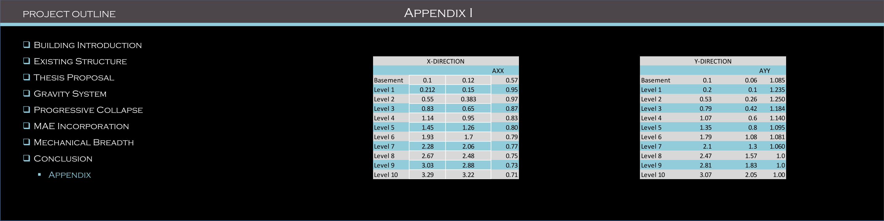
PROJECT OUTLINE Appendix I
AXX
Basement 0.1 0.12 0.57
Level 1 0.212 0.15 0.95
Level 2 0.55 0.383 0.97
Level 3 0.83 0.65 0.87
Level 4 1.14 0.95 0.83
Level 5 1.45 1.26 0.80
Level 6 1.93 1.7 0.79
Level 7 2.28 2.06 0.77
Level 8 2.67 2.48 0.75
Level 9 3.03 2.88 0.73
Level 10 3.29 3.22 0.71
X-DIRECTION
AYY
Basement 0.1 0.06 1.085
Level 1 0.2 0.1 1.235
Level 2 0.53 0.26 1.250
Level 3 0.79 0.42 1.184
Level 4 1.07 0.6 1.140
Level 5 1.35 0.8 1.095
Level 6 1.79 1.08 1.081
Level 7 2.1 1.3 1.060
Level 8 2.47 1.57 1.0
Level 9 2.81 1.83 1.0
Level 10 3.07 2.05 1.00
Y-DIRECTION

Building Introduction
Existing Structure
Problem Statement
Proposed Solution
Gravity System
Progressive Collapse
MAE Incorporation
Mechanical Breadth
Conclusion
Appendix
PROJECT OUTLINE Appendix I
P(kips) Moment( k-ft) dxe dye dxeCd /I dyeCd /I Dxe Dye Dmax=0.010hsx
Basement 21 359 0.1 0 0.166666667 0 0 0 1.8 Pass
Level 1 52 1125 0.212 0.02 0.35 0.03 0.187 0.033 1.44 Pass
Level 2 100 1954 0.55 0.05 0.92 0.08 0.563 0.050 1.44 Pass
Level 3 121 2158 0.83 0.09 1.38 0.15 0.467 0.067 1.32 Pass
Level 4 159 2702 1.14 0.14 1.90 0.23 0.517 0.083 1.32 Pass
Level 5 213 3618 1.45 0.19 2.42 0.32 0.517 0.083 1.32 Pass
Level 6 290 4917 1.93 0.25 3.22 0.42 0.800 0.100 1.8 Pass
Level 7 355 6016 2.28 0.31 3.80 0.52 0.583 0.100 1.44 Pass
Level 8 454 7699 2.67 0.37 4.45 0.62 0.650 0.100 1.71 Pass
Level 9 586 9941 3.03 0.45 5.05 0.75 0.600 0.133 1.8 Pass
Level 10 43 737 3.29 0.51 5.48 0.85 0.433 0.100 1.8 Pass
Vbase = 2394
X-D
ire
ctio
n
No
To
rsio
nal
Irre
gula
rity

Building Introduction
Existing Structure
Problem Statement
Proposed Solution
Gravity System
Progressive Collapse
MAE Incorporation
Mechanical Breadth
Conclusion
Appendix
PROJECT OUTLINE Appendix I
P(kips) Moment( k-ft) dxe dye dxeCd /I dyeCd /I Dxe Dye Dmax=0.010hsx
Basement 21 248.5 0 0 0 0 0 0 1.8 Pass
Level 1 52 766.9 0.1 0.2 0.17 0.33 0.167 0.333 1.44 Pass
Level 2 100 1484.7 0.25 0.53 0.42 0.88 0.250 0.550 1.44 Pass
Level 3 121 1622.6 0.36 0.79 0.60 1.32 0.183 0.433 1.32 Pass
Level 4 159 1943 0.47 1.07 0.78 1.78 0.183 0.467 1.32 Pass
Level 5 213 2462.3 0.58 1.35 0.97 2.25 0.183 0.467 1.32 Pass
Level 6 290 3372.6 0.74 1.79 1.23 2.98 0.267 0.733 1.8 Pass
Level 7 355 4054.3 0.86 2.1 1.43 3.50 0.200 0.517 1.44 Pass
Level 8 454 4904 0.99 2.47 1.65 4.12 0.217 0.617 1.71 Pass
Level 9 586 6332 1.09 2.8 1.82 4.67 0.167 0.550 1.8 Pass
Level 10 43 470 1.16 3.07 1.93 5.12 0.117 0.450 1.8 Pass
Vbase = 2394
Y-D
ire
ctio
n
No
To
rsio
nal
Irre
gula
rity

Peripheral Tie Reinforcement:
Required tie strength (lb/ft):
𝐹𝑜 = 6𝑤𝐹𝐿1𝐿𝑝
𝑤𝑓 = 1.2𝐷 + 0.5𝐿
𝐿1 = greatest bay length
Reinforcement Design:
𝐴𝑚𝑖𝑛 = 𝐹𝑖
∅ ∙ Ω ∙ 𝐹𝑦
PROJECT OUTLINE Peripheral Ties
Building Introduction
Existing Structure
Problem Statement
Proposed Solution
Progressive Collapse
MAE Incorporation
Mechanical Breadth
Conclusion

PROJECT OUTLINE Peripheral Ties
Building Introduction
Existing Structure
Problem Statement
Proposed Solution
Progressive Collapse
MAE Incorporation
Mechanical Breadth
Conclusion
Fp As min Bars Spacing
East-West 83.2 1.23 (3) No.6 12
North-South 75.8 1.12 (3) No.6 12
3rd to 8th Level
Fp As min Bars Spacing
East-West 88.7 1.314 (4) No.6 9
North-South 80.7 1.2 (3) No.6 12
Basement to 2nd Level
Fp As min Bars Spacing
East-West 115 1.7 (4) No.6 9
North-South 104.8 1.55 (4) No.6 9
Penthouse Level
Fp As min Bars Spacing
East-West 67 0.99 (3) No.6 12
North-South 61 0.9 (3) No.6 12
Roof Level