Alarma, Manual
71
XL-1S SECURITY SYSTEM HOOKUP AND INSTALLATION INSTRUCTIONS Subsidiary of Pittway Corp. 149 Eileen Way, Syosset, NY 11791 N9471V1 06/98
-
Upload
lindsey-schultz -
Category
Documents
-
view
137 -
download
0
Transcript of Alarma, Manual
XL-1S
SECURITY SYSTEM
HOOKUP AND INSTALLATION INSTRUCTIONS
Subsidiary of Pittway Corp.149 Eileen Way, Syosset, NY 11791
N9471V1 06/98

ii
THANK YOU for your purchase of the FBIIXL-1SILVER.
The purpose of the manual is to give you a brief overview of the XL-1S control panel, and provideinstructions for installing a basic system. FBII is always available to serve YOU. Our SALES andTECHNICAL SUPPORT staff are available to assist you in any way possible.
FORTECHNICAL SUPPORT,
CALL TOLL FREE:(800) 645-7492
Before you call Technical Service, be sure you:
; Check the wiring diagram and verify your connections.
; Check all fuses.
; Assure that the transformer and backup battery voltages are supplying the proper voltage levels.
; Verify your programming information.
; Read this manual thoroughly.
; Consult the Troubleshooting Section of this Manual.
; Note the proper model number of this product, and the version level (if known) along with anydocumentation that came with the product.
; Have your company name and telephone number ready.
This information will allow us to service you more quickly and effectively. Please, remember to BE PATIENTwhile waiting on the telephone; your call will be answered as soon as possible.
FOR YOUR CONVENIENCE, a System Planning Worksheet and a Programming Worksheet is included atthe back of this manual. These can be removed to help you record account information.
iii
Table of Contents• • • • • • • • • • • • • • • • • • • • • • • • • • • • • • • • • • • • • • • • • • • • • • • • • •
XL-1S to XL-2 Comparison ..................................................................................................................................v
Conventions Used in This Manual .................................................................................................................vii
Section 1 - Introduction...................................................................................................................................1–1
Section 2 - System Wiring and Hookup........................................................................................................2–1System Wiring Diagram ...................................................................................................................................2–1Terminal Connections .......................................................................................................................................2–2Auxiliary Device Current Draw Worksheet ....................................................................................................2–6Wiring Information for Keypads & Other Devices..........................................................................................2–7Keypads & Other Devices .................................................................................................................................2–7
Section 3 - PC Board Mounting......................................................................................................................3–1Mounting the PC Board ....................................................................................................................................3–1
Section 4 - Keypad Mounting..........................................................................................................................4–1XK-104 Keypad..................................................................................................................................................4–1Mounting 6805 Keypad.....................................................................................................................................4–2
Section 5 - Keypad Layout...............................................................................................................................5–1Keypad Sounder ................................................................................................................................................5–3
Section 6 - System Operations........................................................................................................................6–1Power Up/System Reset....................................................................................................................................6–1Arming the System............................................................................................................................................6–1Stay Arming.......................................................................................................................................................6–1Instant Arming..................................................................................................................................................6–1Stay/Instant Arming .........................................................................................................................................6–2Disarming ..........................................................................................................................................................6–2Reset...................................................................................................................................................................6–2Bypass ................................................................................................................................................................6–2Auto Unbypass ..................................................................................................................................................6–3Manual Unbypass .............................................................................................................................................6–3User Code Programming...................................................................................................................................6–3User Deletion.....................................................................................................................................................6–4Keypad Emergency Conditions ........................................................................................................................6–4
Section 7 - Installer Modes..............................................................................................................................7–1Installer Mode 1 (Installer Keypad Programming).........................................................................................7–1Installer Mode 2 (System Log View) ................................................................................................................7–1Installer Mode 3 (Unattended Download) .......................................................................................................7–2Installer Mode 4 (On-Line Download) .............................................................................................................7–2
Section 8 - System Programming ..................................................................................................................8–1General...............................................................................................................................................................8–1Programming Questions ...................................................................................................................................8–1Zone Programming..........................................................................................................................................8–10
Section 9 - Data Entry via LED & LCD Keypads .......................................................................................9–1Entering Programming Mode via Either LED or LCD Keypads ...................................................................9–1What You See on the LED Keypad ..................................................................................................................9–1What You See On The LCD Keypad ................................................................................................................9–2How to Enter Data ............................................................................................................................................9–2

Table of Contents (cont’d)• • • • • • • • • • • • • • • • • • • • • • • • • • • • • • • • • • • • • • • • • • • • • • • • • •
iv
Section 12 - System Defaults.........................................................................................................................10–1
Section 11 - Summary of Keypad Functions.............................................................................................11–1User Functions ................................................................................................................................................11–1Installer Mode .................................................................................................................................................11–1
Appendix A - Central Station Reporting Formats ................................................................................... A–1Standard (3X1) ................................................................................................................................................. A–14X2..................................................................................................................................................................... A–2
Appendix B - Troubleshooting ...................................................................................................................... B–1
Appendix C - XL-1S System Planning Worksheet..................................................................................... C–1
Appendix D - XL-1S System Programming Worksheet ...........................................................................D–1
Appendix E - Warnings and Limitations .................................................................................................... E–1
Appendix F - FCC Statement and Telephone Problems ......................................................................... F–1
Appendix G - Warranty ...................................................................................................................................G–1
v
XL-1S to XL-2 Comparison• • • • • • • • • • • • • • • • • • • • • • • • • • • • • • • • • • • • • • • • • • • • • • • • • •
The XL-1S is an enhanced version of the XL-2 control panel. Some new features have been added and othershave been modified. The following is a quick comparison.
XL-1S NEW & MODIFIED FEATURES XL-2 SIMILAR FEATURES
Call Waiting /PBX Dialing - 1 digit entry(program quest. #01 & #02)
Multiple digits required
Smoke Power or ProgrammableTrigger #1 Output/Terminal P1-T1(program quest. #07)
Smoke Power Only
Programmable Trigger #2Output/Terminal P1-T2 (program quest.#07)
NONE
CS Test Timer Offset (program quest.#14)
NONE
Cancel Code (program quest. #18) NONE; Restore Code OnlyEuropean Ring Detect (program quest.#05)
NONE
Exit Error Warning (always enabled) NONEBypass In Stay - Any Controlled Zone canbe Bypassed in Stay Mode (program quests.#10-13)
Interior Zones Only Bypassed in Stay Mode
System Stabilization on Power Up - toEliminate Motion Detector False Alarms
NONE
Fast Loop Response (10 msec) Optionby Zone (program quests. #10-13)
NONE
AC (50/60 HZ) Based System Real TimeClock (program quest. #05)
Software Based System Timing
Bell Supervision - New NFPA 72Requirement (program quest. #13)
NONE
Stay Mode 40 Sec. Dialer Delay w/Bell& Keypad Sounder Warning for AllZones (program quest. #05)
Stay Mode Entry Delay w/Keypad SounderWarning for Exit/Entry Zones Only
LED Zone Display & Keypad Sounderduring Entry (always enabled)
Keypad Sounder Only
XL-1S FEATURE CHANGES XL-2 SIMILAR FEATURES5 Zones - 4 Programmable & WiredPanic or Keyswitch Zone (programquest. #10-13)
7 Zones - 6 Programmable & WiredPanic or Keyswitch Zone
System Wide Restore Code Enable(program quest. #19)
Restore Codes selectable by each zone
System Wide 15 Sec. Dialer Delay forcontrolled zones (program quest. #07)
15 Sec. Dialer Delay selectable by each zone
User 5 - Arm Only User capabilityremoved
User 5 - Arm Only User optional

XL-1S to XL-2 Comparison (cont’d)• • • • • • • • • • • • • • • • • • • • • • • • • • • • • • • • • • • • • • • • • • • • • • • • • •
vi
Ring Count Options: 0, 4, 8, 12, (programquest. #07)
Ring Count Options: 0 - 15
Quick Commands (Quick Arm, QuickForced Arm & Quick Bypass)capability removed
Quick Arm & Quick Forced Arm/QuickBypass programmable
= Reset (* key) always enabled for FireAlarms Only
Reset (* key) programmable for BothBurglar & Fire Alarms
LCD Keypad Descriptors NOTProgrammable (Default = Zone 1, Zone 2,etc.)
LCD Keypad Descriptors Programmable
CS Reporting Formats (Ext. & PartialExt.) capability removed
CS Reporting Formats (Ext. & Partial Ext.)programmable
CS Test Keypad Ringback alwaysSilent
CS Test Keypad Ringback always Audible
vii
Conventions Used in This Manual• • • • • • • • • • • • • • • • • • • • • • • • • • • • • • • • • • • • • • • • • • • • • • • • • •
Before you begin using this manual, it is important that you understand the meaning of the following symbols(icons).
UL These notes include specific information which must be followed if you are installing this systemfor a UL Listed application.
These notes include information that you should be aware of before continuing with theinstallation, and which, if not observed, could result in operational difficulties.
This symbol indicates a critical note that could seriously affect the operation of the system, orcould cause damage to the system. Please read each warning carefully. This symbol alsodenotes warnings about physical harm to the user.

viii

1–1
S E C T I O N 1
Introduction• • • • • • • • • • • • • • • • • • • • • • • • • • • • • • • • • • • • • • • • • • • • • • • • • •
The XL-1S Security System is a state of the art microprocessor-based control/communicator.Programming can be performed through any of the compatible keypads or the system can beuploaded and downloaded remotely using the EZ-Mate PC Downloader Software. In addition,remote control actions (arming, disarming, bypassing, etc.) can be performed by the software.Programming options are stored in non-volatile reprogrammable EEPROM memory and thatinformation which has been programmed will not be lost in the event of a complete loss ofpower. Other features of the XL-1S include:
• 5 Zones (4 fully programmable plus a wired panic zone or keyswitch zone)
• 2 types of compatible keypads (LCD & LED, four wire devices with up to four per system)
• 6 user codes with capability for ambush code
• Fast Loop Response (10 msec) selectable by zone
• NFPA 72 Bell Supervision
• CS Test Timer Offset
• English readout keypads available
• Upload/Download with remote commands with answering machine bypass
• Default Lockout option to prevent hostile account takeovers
• Indications on keypad for AC loss, Low Battery and Communication Failure
• Central Station reporting for Alarms, Troubles, Restores, Bypasses, Openings, Closings,Ambush, Panic, 24HR. Test, Cancels, AC loss, and Low Battery
• Can be programmed as a Local System (No CS Reporting)
• 4 wire smoke detectors with Fire Verification logic plus smoke power reset
• Exit Error Warning
• European Ring Detect
• 2 programmable trigger outputs for various functions (including armed/ready indicationand glass break detector reset)
• Input Power: 12VAC 20VA; 12VDC, 4 - 7 AH
• Output Power: 11.5 - 13.1VDC, 500mA
• Bell Output Power: 10 - 15.5VDC, 1A

XL-1S Hookup and Installation Instructions
1–2

2–1
S E C T I O N 2
System Wiring and Hookup• • • • • • • • • • • • • • • • • • • • • • • • • • • • • • • • • • • • • • • • • • • • • • • • • •
System Wiring Diagram
CONTROL PANELPOWER
DETAIL A
12 13
1 2 3 4
ZONE
SMOKE DETECTOR9.5 - 12.2VDC
LISTED HOUSEHOLD THERMOSTAT ESL 104
MODEL ESL2048 EOL RELAY
RE
D
BLA
CK
BR
OW
N
BR
OW
N
2.2K EOL RESISTOR
UL LISTED SMOKE DETECTOR MODEL ESL445AT
UL INSTALLATIONS REQUIRE LISTEDEND-OF-LINE DEVICE. USE RESISTORFROM EOL22 KIT. LOOK FOR LISTINGMARK ON ITEM.
WARNING:THIS UNIT INCLUDES AN ALARM VERIFICATIONFEATURE THAT WILL RESULT IN A DELAY OF THESYSTEM ALARM SIGNAL FROM THE INDICATEDCIRCUITS. THE TOTAL DELAY (CONTROL UNITPLUS SMOKE DETECTOR) SHALL NOT EXCEED60 SECONDS. NO OTHER INITIATING DEVICESSHALL BE CONNECTED TO THESE CIRCUITSUNLESS APPROVED BY THE LOCAL AUTHORITYHAVING JURISDICTION.
CIRCUIT CONTROL UNIT SMOKE DETECTOR(ZONE) DELAY-SEC MODEL DELAY-SEC
_______ _____20______ ______ __________
PRODUCT COVERED UNDERUS PATENT #4,791,658
WARNING: To prevent risk fromelectrical shock, de-energize the systemcontrol unit and disconnect the telephonelines before servicing this unit.
XL-1S
FCC Registration Number A E398E-69554 AL-E Ringer E quivalence 0.0B
References: Hookup and Installat ion Instructions N 9471 and Owner’s Manual N9472 LOAD NO.: 7
NOTES: 1. Connect to a grounded metal water pipe (16ga. at 15 ft.) 2. Total AUX. power available (including keypad power) is 500mA max (300mA max for UL installations). Used for connection of devices rated from 11.5 to 13.1VDC. 3. System must be tested on a weekly basis. For information, refer to manual. 4. Do not connect the transformer to a switch controlled receptacle. Power varies with transformer (SEE NOTE 2). 5. Installation of equipment and wiring methods are required to be in accordance with the National Electrical code and ANSI/NFPA No. 74. 6. Battery capacity for Emergency Standby is a minimum of 4 hours. Under normal conditions this battery will last 3 years. Use only exact replacements. 7. Maximum of 4 keypads. Available keypads include: XK-104 and 6805. 8. Limited energy cable must be used. 9. Non-replaceable fuse (F3). Return to manufacturer if blown. Do not solder in field.10. Maximum for UL installations: Entry Delay, 45 sec.; Exit Delay, 60 sec.11. For connection of VS-299 Siren Driver. Constant positive (+) unregulated output.12. The PANIC or KEYSWITCH connected to terminals 5 & 7 is to be no more than 3 ft. from the control unit with no barriers in between. 13. Programmable trigger outputs. If used for smoke detector power reset see Detail A. See manual for programming information. Use model XL-2GTC trigger cable.
SYSTEM DEFAULT RESET JUMPERS
TRANSFORMER12VAC, 20VA
(Connect to 24 HR.120VAC, 60 Hz Outlet
SEE NOTE 4)
+
-
SIREN
-+
+ __+
SMOKE DETECTOR
POWER (9.5-12.2VDC,
50mA max)
BELL
22 16 17 18 19 20 21 9 10 11 12 13 14 15
CONSTANT DC POWER (+)10-15.5VDC
(SEE NOTE 11)
KEYPAD (SEE NOTE 7)
BLA
CK
YE
LLO
W
GR
EE
N
RE
D
FIRE & BURGLARYALARM OUTPUT (11.5-13.1VDC,
1A max) HOME
TELCO
BR
OW
N
GR
AY
HO
ME
GR
EE
N
RE
DTE
LCO
AUX POWER12VDC Reg., 500mA Max.
(SEE NOTE 2)
+ _PANIC
2.2K
2.2K
4
3
2
1
EARTH GND. (SEE NOTE 1)
5
6
7
8
2.2K
2.2K
ZONE 1
ZONE 2
ZONE 3
ZONE 4
JP1 JP2
To re-load factory default values, remove all power(AC & DC). Short JP1 to JP2. With short still applied,re-apply power (AC then DC), wait 5 seconds, thenremove short with power still applied.
ZONE
1
2
3
4
PANIC
(+)
1
3
4
6
7
(-)
2
2
5
5
5
TERMINALS
CONNNECTIONS FOR HOUSEHOLD FIRE/BURGLAR ALARM SYSTEM
P1
VB
ELL
T1 T2
+
BLACK
RED
12V, 4-6AHBATTERY
MODEL 1240A(SEE NOTE 6)
_
TRIGGEROUTPUTS(SEE NOTE 13)
Aux. Power
Bell Power
F3Battery4 Amps
This fuse is NOT replaceable.(SEE NOTE 9)
F1
F2
3 Amps
1 Amp
MODEL 368 CORD TO RJ31X OR CA31A JACK
SYSTEM STABILIZATION MODE: Upon initial powerup of the system, all of the lights on the LEDkeypad(s) will go ON and then go OFF for approximately 2 min. 10 secs and/or the LCD keypad(s) willdisplay STAND BY! for approximately 2 min. 10 secs. This occurs on a total powerup (if ARMED orDISARMED in its prior state) or after a system reset. If the total system power is lost then upon powerrestoral, the system will return to the previous arming state. The 2 min. 10 secs. interval is used to allowmotion detectors (interior zones) to stabilize on power up in order to prevent false alarms. THIS OPTIONCAN BE DISABLED BY MOMENTARILY (5 second minimum) PUTTING A JUMPER BETWEEN TERMINALS13 AND 12.
XL-1S Hookup and Installation Instructions
2–2
Terminal ConnectionsTERMINALS DESCRIPTION1(+) & 2(-) Zone 1 (Requires 2.2K EOL resistor) [Default = DELAY]3(+) & 2(-) Zone 2 (Requires 2.2K EOL resistor) [Default = INTERIOR]4(+) & 5(-) Zone 3 (Requires 2.2K EOL resistor) [Default = PERIMETER]6(+) & 5(-) Zone 4 (Requires 2.2K EOL resistor) [Default = PERIMETER]
ZONE INFORMATION:
Normally closed devices may be wired in series and/or normally opendevices in parallel with the 2.2k ohm end of line resistor on all zones(Refer to the wiring diagram). The standard loop response time is 280 mson all zones. Each zone can be programmed for Fast Response (10 ms)in programming (see questions #10-13). The factory default values foreach zone is listed in the table above, however any zone can beprogrammed for the following types: Delay, Perimeter, Interior, Fire, 24Hr. Alarm, or 24 Hr. Trouble. Further explanation of the zone types canbe found in the System Programming section of this manual.NOTE: Loop response is defined as the minimum time required for afault to trip a zone.
5 & 7 PANIC CIRCUIT OR KEYSWITCH:
Normally Open PANIC circuit. This hardwired panic is a 24-hour zonethat can be programmed for silent or audible operation. The panic circuitwill activate with each violation, therefore a latched device is notrecommended. A momentary device is recommended. For ULinstallations, the panic switch connected to these terminals is to belocated no more than 3 feet from the control unit, with no interveningbarriers (this is a supervision requirement only). If the keyswitch optionis selected (see programming question #05, location 2), then eachactivation of the keyswitch will arm and disarm the system.
NOTE: EOL resistor is not required on this zone and is not supervised.This zone does not report restore codes. If a supervised zone with restorereporting ability is desired, then program one of the 4 ZONES as a 24Hr.Alarm. If used as a keyswitch, then triggers are available for either anarming or ready status indication (see programming question #07,location 4).
8 EARTH GROUND:
Connect this grounding lug to a cold water pipe utilizing #18AWG wire ata distance of no greater than 15 ft. Use a non-corrosive metal strap firmlysecured to the pipe to which the lead is electrically connected andsecured. If the premises pipes terminate in PVC, this terminal must beconnected to a six- (6) foot grounding rod.
9 10 11 12 KEYPADS:
A maximum of 4 keypads, either XK-104 or 6805, may be wired to theseterminals. The connections are as follows; 9 (BLACK = negative), 10(YELLOW = data in), 11 (GREEN = data out) and 12 (RED = positivepower). Each keypad draws approximately 30mA. Maximum keypadlength is 500 feet using 22-gauge wire. NOTE: In some installations, itmay be necessary to use shielded wire to prevent radio frequencyinterference.
Section 2 - System Wiring and Hookup
2–3
9 (-) & 12 (+) REGULATED POWER (11.5 - 13.1VDC):
The total regulated output power for motion detectors and other externaldevices is 500mA at 11.8 - 12.5V for residential applications, or 12.0 -12.5V for commercial applications, with less than 100 mVPP ripple. Thetotal regulated output capacity of the XL-1S includes the power availablefrom these terminals (9 & 12) as well as the power used by the keypadsand smoke detectors. Therefore, to determine the total power availablefrom these terminals subtract the power consumed by the keypads andsmoke detectors. See Auxiliary Device Current Draw Worksheet.
12 (+) 13 (-) SMOKE DETECTOR POWER OR TRIGGER #1 OUTPUT:SMOKE DETECTOR POWER: This system will accept 9.5 - 12VDC four (4)wire smoke detectors only. Approximately 50mA of current is available atthese terminals for powering all detectors and an EOL relay modelESL2048. For UL installations see wiring diagram for hookup. NOTE:Trigger #1 must be selected for smoke detector power (see programquestion #07, location 3).
These terminals adhere to the fire verification and reset logic, which isexplained in the zone types section of this manual. Manual reset of smokedetector power can be accomplished by entering a valid user code afterclearing alarm memory or using the asterisk (*) key.
14 15 16 17 TELEPHONE LINE:
Connect the model 368 cord as follows; 14 (GREEN = Telco Tip), 15 (RED= Telco Ring), 16 (BROWN = Home Tip), 17 (GRAY = Home Ring). Insertthe plug into an USOCRJ31X jack (or a CA31A jack for Canadianinstallations).
The FCC registration number is (AE398E-69554 AL-E), and the ringerequivalence is (0.0B). The system should not be connected to party lines,or coin operated phones.
If this control panel will be used for uploading, downloading or remote command applications, thetelephone line connected to the control panel must not be shared with a fax machine or modem.Furthermore, this device should not be connected to a phone line that has call waiting, unless thecall waiting interrupt numbers are programmed into the panel dialing sequence.
18(+) CONSTANT DC POWER:
This terminal delivers constant unregulated 10.0-15.5VDC power fordevices requiring a constant power such as VS279. It is connected to abell fuse (F3). NOTE: Constant power for these devices can also beobtained by splicing the RED (+) battery lead with an in-line fuse of 3Amps.
19(+) & 20(-) BELL OUTPUT:
The total output power available for sounding devices is 1 amp at 10.5 -15.5 VDC for residential applications, or 12.0 - 14.4 VDC for commercialinstallations (750 mA for UL installations). These terminals will deliverCONSTANT output on BURGLARY, AUDIBLE PANIC and BELL TEST.On a FIRE condition, a PULSED output will be generated. There areseparate bell cutoff times programmable for Burglary and Fire conditionswithin the programming sequence. For UL Household Fire WarningSystem installations, the speaker must be mounted indoors for bestaudibility. Also, for UL installations, use only one speaker. NOTE: Beforeconnecting sounding devices please consult their specifications for proper

XL-1S Hookup and Installation Instructions
2–4
current draw. Otherwise, the bell fuse (F3) may be blown. An optionexists to supervise the bell output terminals if zone 4 is programmed as afire zone (see program questions #10-13); refer to the following notes:
P1: VBELL (+) T1 (-) TRIGGER #1 OUTPUT:
P1-VBELL (+) & P1-T1 (-) or terminals 12 & 13 can be used for a trigger#1 output. See programming question #07, location 3 for valid triggertypes. NOTE: In order to connect devices to the triggers use connectorXL-2GTC (trigger cable). Unless otherwise specified, the trigger output isnormally floating and actively sinks on activation (switched negative).
NFPA 72 REQUIREMENT: All theinterconnecting pathways, (cable, wire,etc.) between the alarm system initiatingdevice (control panel) and the signalingdevice (bell, speaker, siren, etc.) shallbe monitored for an occurrence of anopen circuit, which prevents the normaloperation of the system. An occurrenceof an open circuit shall be indicated by adistinctive trouble signal.
BELL SUPERVISION (Mechanical Bell) - To meet the NFPA 72 requirementprogram zone 4 as a Fire Zone (program question #13, locations 1& 2). The bell is then supervised for an open circuit (not a short circuit)across the bell output terminals; the keypad will indicate that a FireTrouble condition has occurred and Fire Trouble is reported to the CS ifenabled (program question #18, location 3). If the bell is already ringing,the supervision will not take effect until after bell cutoff time. See thediagram on the next page:
Mechanical Bell
22 (+)
23 (-)
Bell Out put
SIREN SUPERVISION (Self Contained Siren/Speaker) - To meet the NFPA 72requirement program zone 4 as a Fire Zone (program question #13,location 1). The siren is then supervised for an open circuit (not a shortcircuit) across the bell output terminals; the keypad will indicate that aFire Trouble condition has occurred and Fire Trouble is reported to theCS if enabled (program question #18, location 3). If the siren is alreadysounding, the supervision will not take effect until after bell cutoff time.NOTE: Use FBII models ZR-815C, ZR-815EC or ZR-830EC. See thediagram below:
Self Contained Siren/S peaker
22 (+)
23 (-)
Bell Out put
SPEAKER SUPERVISION (VS-299 Siren/Driver) - To supervise a speakerconnected to the VS-299 Siren Driver connect terminal 1 of theVS-299 to the positive terminal of any zone programmed as a 24Hour Trouble zone (program questions #10 - 13, locations 1 & 2).The speaker is then supervised for an open circuit across the speakerterminals (4 & 5) of the VS-299 and a code is reported to the CS ifenabled (program question #10 - 15, locations 3 & 4). Also, the connectionbetween the bell output terminals and the VS-299 Siren Driver may besupervised by programming zone 4 as a Fire Zone (program
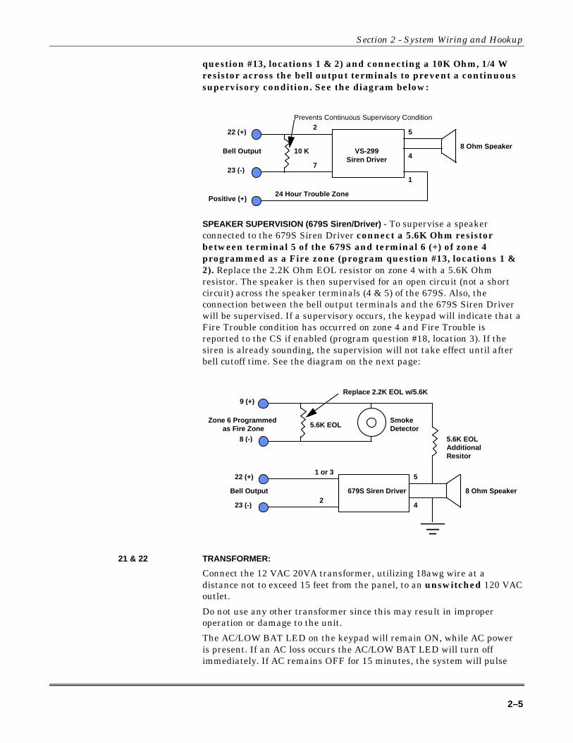
Section 2 - System Wiring and Hookup
2–5
question #13, locations 1 & 2) and connecting a 10K Ohm, 1/4 Wresistor across the bell output terminals to prevent a continuoussupervisory condition. See the diagram below:
VS-299Siren Driver
8 Ohm Speaker
5
4
2
7
22 (+)
23 (-)
Bell Out put
24 Hour Trouble Zone
1
Positive (+)
10 K
Prevents Continuous Supervisory Condition
SPEAKER SUPERVISION (679S Siren/Driver) - To supervise a speakerconnected to the 679S Siren Driver connect a 5.6K Ohm resistorbetween terminal 5 of the 679S and terminal 6 (+) of zone 4programmed as a Fire zone (program question #13, locations 1 &2). Replace the 2.2K Ohm EOL resistor on zone 4 with a 5.6K Ohmresistor. The speaker is then supervised for an open circuit (not a shortcircuit) across the speaker terminals (4 & 5) of the 679S. Also, theconnection between the bell output terminals and the 679S Siren Driverwill be supervised. If a supervisory occurs, the keypad will indicate that aFire Trouble condition has occurred on zone 4 and Fire Trouble isreported to the CS if enabled (program question #18, location 3). If thesiren is already sounding, the supervision will not take effect until afterbell cutoff time. See the diagram on the next page:
9 (+)
8 (-)
679S Siren Driver
Zone 6 Pro grammed as Fire Zone 5.6K EOL
8 Ohm Speaker
5.6K EOLAdditionalResitor
5
4
1 or 3
2
SmokeDetector
Replace 2.2K EOL w/5.6K
22 (+)
23 (-)
Bell Out put
21 & 22 TRANSFORMER:
Connect the 12 VAC 20VA transformer, utilizing 18awg wire at adistance not to exceed 15 feet from the panel, to an unswitched 120 VACoutlet.
Do not use any other transformer since this may result in improperoperation or damage to the unit.
The AC/LOW BAT LED on the keypad will remain ON, while AC poweris present. If an AC loss occurs the AC/LOW BAT LED will turn offimmediately. If AC remains OFF for 15 minutes, the system will pulse

XL-1S Hookup and Installation Instructions
2–6
the keypad buzzer and transmit to the central station, if programmed.THE KEYPAD BUZZER CAN BE SILENCED by entry of any valid usercode. When AC restores the AC/LOW BAT LED will light immediately,and a restore code will be reported, if programmed.
BACKUP BATTERY: The RED (+) and BLACK (-) flying leads must be connected to a 12 VDC4-6AH GELL CELL, to serve as backup power in the event of AC loss.
A battery test occurs approximately every 4.5 minutes. Low batterycondition occurs at nominal 11VDC. The keypad AC/LOW BAT LED andbuzzer will PULSE SLOWLY when a low battery condition is detected.The system reports this condition to the CS if programmed. Batteryrestoral will occur WITHIN 4.5 minutes, at the NEXT battery test. THEBUZZER MAY BE SILENCED by entry of any valid user code.
GROUND START: Ground start capability can be added to the system through addition ofthe FBII Model 117 module. Consult the 117 Installation Instructions forhookup information. With this device some systems can obtain dialtonewhere it is not available. At the moment telephone line seizure occurs,the Telco Tip is momentary connected to earth ground to access dial tone.NOTE: The 117 module has not been tested for use in UL installations.
P1: VBELL, T1 & T2 TRIGGER OUTPUTS (1 & 2):
The control panel contains two programmable trigger outputs. Trigger #1terminals are P1-VBELL (+) & P1-T1 (-) and for Trigger #2 P1-VBELL (+)& P1-T2 (-). See programming question #07, location 4 for valid triggertypes. BY DEFAULT TRIGGER #1 IS ENABLED FOR SMOKEDETECTOR POWER, WHICH CAN ALSO BE OBTAINED FROMTERMINALS 12(+) & 13(-). TRIGGER #2 CANNOT BE SELECTED FORSMOKE POWER. NOTE: In order to connect devices to the triggers useconnector XL-2GTC (trigger cable). Unless otherwise specified, thetrigger output is normally floating and actively sinks on activation.Connect to terminal 12 (+) to obtain a POSITIVE reference point. For ULinstallations, the trigger outputs shall be connected to devices rated tooperate over the range from 10.1 - 14.0 VDC at 50 mA.
Auxiliary Device Current Draw WorksheetDEVICE CURRENT DRAW
FOR EACHNUMBEROF UNITS
TOTAL CURRENTFOR EACH
XK-104 Keypad 30mA ✴6805 Keypad 60mA ✴PIR ✴ ✴Smoke Detector ✴ ✴Glass Break Detector ✴ ✴
✴ ✴
✴ ✴TOTAL CURRENT FOR ALL DEVICES =
(500mA max.)
NOTES: ✴ Only applies if device is powered from control terminals 12(+) & 13 (-).
✴✴ If using devices such as PIRs, smoke detectors, etc., refer tothe specifications for that particular device's current draw. Ifthe total current draw exceeds 500mA, then use anadditional power supply.

Section 2 - System Wiring and Hookup
2–7
Wiring Information for Keypads & Other Devices
Keypads & Other Devices
If single or multiple devices are connected to a single 4-wire or 2-wire run ("daisy chained")to the control terminals, determine the current drawn by the unit(s) connected to the singlewire run, then refer to the Wiring Run Table below to determine the maximum wire lengththat can be safely used for each wire size.
In some cases, the total current drawn may result in a value not shown in the table. Forexample, if you plan to use #22 gauge wire and the total current drawn is 400 mA (a valuebetween 300 mA and 500 mA), the maximum wire length you should use is approximately 65ft. (a length between 50 and 80 ft.). Other maximum wire lengths for values of current notshown in the table can be calculated in a similar manner.
Maximum wire lengths for a device that is "homerun" to the control can also bedetermined from the table, based on the current draw of that device alone.
Wiring Run Table For Devices Drawing Power From Terminals 12 (+) & 13 (-)
TOTAL CURRENT DRAWN BY ALL UNITS ON A SINGLE WIRE RUNWIRE SIZE
50 mA or less 100 mA 300 mA 500 mA#22 500 ft. (152 m.) 250 ft. (76 m.) 80 ft. (24 m.) 50 ft. (15 m.)#20 750 ft. (228.6 m.) 380 ft. (116 m.) 130 ft. (39.6 m.) 80 ft. (24 m.)#18 1300 ft. (396 m.) 650 ft. (198 m.) 220 ft. (67 m.) 130 ft. (39.6 m.)#16 2000 ft. (609.6 m.) 1000 ft. (305 m.) 330 ft. (100.5 m.) 200 ft. (70 m.)
Examples:
1. What is the maximum distance for one XK-104 keypad drawing 30 mA using # 20 gaugewire?
Using the table above, the keypad can be placed no greater than 750 ft. awayfrom the panel.
2. What is the maximum distance for three 6805 keypads drawing 180 mA (60 mA each)using # 20 gauge wire connected in a single wire run?
Using the table above, the farthest keypad can be placed no greater than 292 ft.away from the panel.
3. What is the maximum distance for 5 smoke detectors drawing 0.25 mA (5 µA each) using# 22 gauge wire connected in a single wire run?
Using the table above, the farthest smoke detector can be placed no greaterthan 500 ft. away from the panel.

XL-1S Hookup and Installation Instructions
2–8

3–1
S E C T I O N 3
PC Board Mounting• • • • • • • • • • • • • • • • • • • • • • • • • • • • • • • • • • • • • • • • • • • • • • • • • •
Mounting the PC BoardBefore mounting the printed circuit board, be certain that the appropriate metal knockoutshave been removed. DO NOT ATTEMPT TO REMOVE THE KNOCKOUTS AFTER THECIRCUIT BOARD HAS BEEN INSTALLED.
1. Hang the three mounting clips on the raised cabinet tabs. Observe proper clip orientationto avoid damage to the clip when mounting screws are tightened and to avoid problemswith insertion and removal of the PC board.
2. Insert the top of the circuit board into the slots at the top of the cabinet. Make sure thatthe board rests in the slots as indicated in the diagram shown below.
3. Swing the base of the board onto the mounting clips.4. Place the washer provided over the wire jumpers located within the middle of the PC
board. Secure the PC board to the middle mounting clip of the enclosure through thewasher using the screw provided.
5. Secure the remaining sides of the PC board to the enclosure using the screws provided.
PC BoardKNOCKOUT
DETAIL SIDE VIEWOF BOARD INSERTEDINTO SLOTS
DETAIL SIDE VIEWOF CLIP AND BOARDINSTALLED
BA
DETAIL SIDE VIEWOF CLIP INSTALLATION: A. CABINET TAB WITHOUT CLIP B. CABINET TAB WITH HANGING CLIP
Metal Cabinet
3rd CLIPREQUIRED

XL-1S Hookup and Installation Instructions
3–2
NOTE: The front face of the enclosure can be completely removed from the enclosure to gainunrestricted access to the control panel during installation. The front of the enclosure can beremoved as follows:1. Open the enclosure to its fully extended position (approx. 90 degrees)2. Lift the control panel door and remove the door from the enclosure.

4–1
S E C T I O N 4
Keypad Mounting• • • • • • • • • • • • • • • • • • • • • • • • • • • • • • • • • • • • • • • • • • • • • • • • • •
XK-104 KeypadThe XK-104 Keypad may be surface mounted in the following ways:
A. Directly to a control panel having a keypad cutout on the front of its enclosure.B. Directly to a single or double gang electrical junction box.C. Directly to a wall or other surface.
1. Remove the keypad cover assembly from the rear mountingplate. Insert a small screwdriver blade in the COVER PRY-OFFSLOTS at the lower edge of the keypad (see Diagram 2) andtwist to pry off the cover assembly.2. Mount the rear plate (see Diagram 3).NOTE: The plate is correctly oriented when its part number,molded into the plastic, is upright.
A. Mounting Directly To Control Panel Enclosure:If the control panel has a keypad cutout on the front face of itsenclosure, remove the cutout and mount the plate to theenclosure's face via HOLES "A" (see diagram 3) and the fourscrews and nuts provided.NOTE: The VT-200 attack-proof enclosure does not contain akeypad cutout.
B. Mounting Directly To An Electrical Junction Box:The plate can be mounted directly to a single or double gangelectrical junction box. Use the screw holes provided andHOLES "B" for a single gang box or HOLES "A" for a doublegang box.
C. Mounting Directly To A Wall Or Other Surface:Provide a wiring hole in the mounting surface. Position theplate's WIRING OPENING over the hole and mounting plate,using HOLES "A" and/or "B" in conjunction with appropriatemounting hardware (not provided) for the type of surface.3. Complete the keypad wiring as required for the control withwhich the keypad is to be used.4. Replace the keypad cover assembly on the rear plate. Startingat the upper edge of the plate, engage the plate's two HOLDINGHOOKS (see diagram 3) into the recesses provided for theminside the upper edge of the cover assembly and snap the loweredge of the cover assembly and snap the lower edge of the coveronto the two SNAP HOOKS at the lower edge of the plate.NOTE: (Optional) If desired, cover and plate can be furthersecured together by inserting a screw (provided) into the SLOTat the keypad's lower edge.
NOTE: When surface mounting the keypad, and using screws with heads larger than the screws providedwith the unit, place electrical tape over the screws to prevent them from interfering with the keypadoperation. In the future the back plate of the keypad will provide additional countersinking for screws withlarger heads.
Diagram 2: BOTTOM VIEW OF KEYPAD
COVER
REAR PLATEBREAK-AWAY RIBS (4)(FOR EXPOSED WIRING ENTRY.)
SLOT FOR COVER SECURING SCREW(OPTIONAL)
COVER PRY-OFF SLOTS (2)(TO REMOVE COVER, INSERT SMALLSCREWDRIVER BLADE AND TWIST.)
DOOR
Diagram 3: REAR MOUNTING PLATE
A AB
A AB
N6054
HOLDING HOOKS (2)(FOR HOLDING COVERS UPPER EDGE)
HOLES “A” (4)(FOR MOUNTING TOCONTROL PANEL’SENCLOSURE ORTWO GANGELECTRICAL BOX)
HOLES “B” (2)(FOR MOUNTING TOSINGLE GANGELECTRICAL BOX)
HOLES “A” OR “B”(CAN BE USEDFOR WALL MOUNTING)
SNAP HOOKS (2)(FOR HOLDING COVER’SLOWER EDGE)
BREAK-AWAY RIBS (4)(FOR EXPOSED WIRING ENTRY.)
POST FOR COVERSECURING SCREW (OPTIONAL)
WIRINGOPENING
(FORCONCEALED
WIRING)
XL-1S Hookup and Installation Instructions
4–2
Mounting 6805 KeypadKeypads can be surface mounted or flush mounted as described below. NOTE: After mounting the 6805 LCDKeypad at eye level, you can adjust the display intensity level to suit the user by adjusting the intensitycontrol located behind the keypad door.
SURFACE MOUNTING1. Select a mounting location and place the rear plate of thekeypad on the wall. Mark the location of the cutout for thekeypad wiring cable.2- Create a keypad opening. Connect the keypad wiring tothe control panel w/ 4-wire connector.3- Place the keypad wiring through the cutout and secure theback plate to the wall (see diagram).4- Connect the keypad wiring connector to the keypad andplace the keypad on the mounting plate attached to the wall.5- Secure the keypad to the rear mounting plate by attachingthe 5/8-inch screw provided in the lower hole, located behindthe keypad door.
RECESSED MOUNTING1- Select a mounting location. For recessed mounting thismust be between two studs. The rear mounting plate is notused for recessed installations.2- Create an opening in the wall exactly 4 inches high by 513/16 inches wide.3- Turn over the keypad and remove the Phillips head screw(item 1 on diagram) in the upper left hand side of the keypadprinted circuit board. NOTE: This screw is locatedimmediately to the left of the keypad connector.4- Attach the black metal mounting strap to the rear of thekeypad as follows (see diagram);- Face the pointed end of the mounting strap facing thekeypad front. This will be used to latch onto the inside of thewall.- Place the small white plastic spacer underneath themounting strap. Secure the mounting strap using the 5/8-inch Phillips head screw (supplied) and the plastic spacer tolocation 1.- Secure the other end of the strap (location 2 on diagram) tothe white plastic opening using the Phillips head screwremoved in step 2.5- Connect the white plastic tab into the round openingimmediately behind the keypad door. Place the longerPhillips head screw (included) through the opening inside thekeypad door and begin to tighten the screw. Tighten thescrew and leave the tab in a down position.6- Run the keypad wiring to the control panel and attach thewiring to the keypad.7- Place the keypad into the wall opening with the sidecontaining the black metal strap first until it grabs the insideof the wall.8- After inserting the side of the keypad with the metal strap,insert the other side into the opening until the entire keypadis firmly in the wall.9- Tighten the screw inserted in step 5.
5 13/16,,
4 ,,
(15 cm)
(10 cm)
2 1
3
5–1
S E C T I O N 5
Keypad Layout• • • • • • • • • • • • • • • • • • • • • • • • • • • • • • • • • • • • • • • • • • • • • • • • • •
1. ZONE STATUS LEDsThese LEDs display the current zone status including alarms, bypasses, troubles andfaults. Each condition will cause these LEDs to operate differently as follows:
ALARMS Fast Blink (approx. 150 ms ON - 150 ms OFF).TROUBLES Slow Pulse (approx. 600 ms ON - 600 ms OFF).BYPASSES Wink (100 ms ON - 900 ms OFF). Zone bypasses are displayed as a veryslow wink of the zone LED light.FAULTED ZONES Solid ON. Faulted zones are the lowest priority indication.Faulted burglary zones are displayed with the LED solidly ON while the system isdisarmed.NORMAL OFF
Upon Entry to disarm the system the keypad sounder will annunciate to warn the user to disarm it.In addition, the respective zone LED(s) will be ON to indicate zones which are violated (ex: entrydoor and motion detector).
2. ARM/DISARM LEDThis LED indicates whether the system is currently armed (ON) or disarmed (OFF).
Fast Blink Alarm ModeSlow Wink Fail to Communicate with Central Station
6805 KEYPAD
STAY321
4 5 6
7 8 9
* #0
BYPASS
INSTANT
CODE
7
8
9
10.
5
2
SYSTEM READY
11 ARM
AC/LB
READY
1
2
3
4
XK-104 KEYPAD
COVEROPEN
Stay Instant
Bypass Code
* 0 #
7 8 9
4 5 6
1 2 3
PAF
2
3
6
1
7
9
10
8
12
INSTANT
STAY
4 5
XL-1S Hookup and Installation Instructions
5–2
3. STAY LEDThis LED displays whether the system has been armed in the STAY mode or theSTAY/INSTANT mode. If the INSTANT LED is ON and the STAY LED is ON, then thesystem is in the STAY/INSTANT mode. If the INSTANT LED is OFF and the STAY LEDis ON, then the system is in the STAY mode only. In either mode the STAY LEDindicates the following:
ON Interior zones are bypassedOFF Interior zones are normal
4. INSTANT LEDThis LED displays whether the system has been armed in the INSTANT orSTAY/INSTANT mode, meaning that the system is currently armed, all delay zones areinstant and all interior zones are bypassed. If the STAY LED is OFF and the INSTANTLED is ON, then the system is in the INSTANT mode. If the STAY LED is ON and theINSTANT LED is ON, then the system is in the STAY/INSTANT mode.
ON Delay zones are currently instantOFF Delay zones are normal
5. AC/LOW BATTERY LEDThis indicator light displays the current power status of the panel as follows;
ON AC is presentOFF No AC, running on battery backupSlow Blink Low battery condition detected
6. READY LEDThis LED displays whether the system is ready for arming. The READY light is commonto all BURGLARY ZONES with the following indications:
ON System ready to be armedOFF System not ready to be armedSlow Blink Indicates Installer programming modeFast Blink Alarm Memory Mode
7. STAY BUTTONThe STAY button enables arming the system, excluding zones programmed as interiorzones. This will provide exterior protection of the location while allowing full accessthroughout the interior.
8. BYPASS BUTTONThe BYPASS button is used to temporarily exclude protection to a specific zone.
9. INSTANT BUTTONIf enabled, the INSTANT button enables arming the system in the INSTANT mode andwith the STAY button it enables arming the system in the STAY/INSTANT mode. NOTE:INSTANT mode is enabled in question #05, location 4.
10. CODE BUTTONThe CODE button is used to enter the installer programming mode and entry of usercodes.
11. LCD DISPLAYThe LCD display shows the current status in a two line by twelve character format.
12. KEYPAD AUXILIARY KEYS (XK-104 KEYPAD ONLY)Pressing the two keys (top & bottom) labeled F (Fire), A (Auxiliary) and P (Panic) at thesame time initiates a CS transmission, if programmed, of PANIC, AUXILIARY(Emergency) or FIRE, annunciates the keypad sounder and turns on the bell output. Ifnot programmed to transmit, these keys can only result in a local warning as follows (seequestion #05, location 1):

Section 5 - Keypad Layout
5–3
Keypad Sounder - Steady for PANIC, Pulsing for FIRE and AUXILIARYBell Output - Steady for PANIC, Pulsing for FIRE
See the Keypad Emergency Conditions section for alternate auxiliary keys.
Keypad SounderThe keypad sounder annunciates differently to indicate the following conditions:
CHIRP - Keypad sounds a short chirp to confirm each keystroke.
STEADY - The keypad will make a steady sound during entry time, and/or duringburglary alarm.
CHIME - steady 1 second tone (SYSTEM DISARMED ONLY).
ACKNOWLEDGE - Upon successful entry of a certain commands the system will soundfor approximately half a second.
PULSING - A pulsing sound (approximately half a second ON then OFF) indicates atrouble condition such as AC loss, Low Battery, or Fire Zone.
NEGATIVE ACKNOWLEDGMENT - Upon entry of an illegal command the keypad willsound four short beeps. For example, if attempting to define a new user and the masteruser is not entered, four short beeps will be made indicating that the command wasunsuccessful.
SOUNDER RINGBACK - Several short beeps to indicate successful communication tothe Central Station. This occurs for all signals, excluding ambush and silent zones.
FAST PULSING SOUNDER- Sound generated during entry time period AFTER analarm condition has occurred and the system reached bell cutoff. A pulsing sounder willfollow the bell output on Fire conditions. Trouble conditions also generate a pulsingsounder and may be silenced through entry of a valid user code.
The keypad is non-operational if none of the LEDs are lit and the keypad does not beep whenkeys are pressed. This is an indication that service is required. Consult the troubleshooting sectionof this manual.

XL-1S Hookup and Installation Instructions
5–4

6–1
S E C T I O N 6
System Operations• • • • • • • • • • • • • • • • • • • • • • • • • • • • • • • • • • • • • • • • • • • • • • • • • •
Power Up/System Reset
SYSTEM STABILIZATION MODE: Upon initial powerup of the system, all of thelights on the LED keypad(s) will go ON and then go OFF for approximately 2 min.10 secs and/or the LCD keypad(s) will display STAND BY! for approximately 2 min.10 secs. This occurs on a total powerup (if ARMED or DISARMED in its prior state)or after a system reset. If the total system power is lost then upon power restoral,the system will return to the previous arming state. The 2 min. 10 secs. interval isused to allow motion detectors (interior zones) to stabilize on power up in order toprevent false alarms. THIS OPTION CAN BE DISABLED BY MOMENTARILY (5 secondminimum) PUTTING A JUMPER BETWEEN TERMINALS 13 AND 12.
Arming the SystemThe system can be armed only if all burglary zones are good (not faulted). On LED basedkeypads this requires that the READY LED be on.
On LCD keypads the following message will appear:
SYSTEM: READY
TO ARM: Enter any programmed four-digit user. NOTE: The factory default for user #1 is1234.
The ARMED LED will light and the user may exit through an exit/entry zone for the timeperiod programmed as the exit delay. The system can be armed without the backup batterybeing connected, however the AC/LB light will flash.
LCD Based keypads will display:
ON: AWAY
Stay ArmingTO ARM: Press the STAY BUTTON followed by a four-digit user code.
The ARMED and STAY LEDs will light on LED based keypads.
LCD based keypads will display:
ON: STAY
The system is armed at this time with all programmed interior zones excluded.
Instant ArmingTO ARM: Press the INSTANT BUTTON followed by a four-digit user code.
The ARMED and INSTANT LEDs will light on LED based keypads.
LCD based keypads will display:
ON: INSTANT
XL-1S Hookup and Installation Instructions
6–2
The system is armed at this time with all programmed delay zones instant; this eliminatesthe exit/entry time delays. NOTE: INSTANT arming is ALWAYS enabled (see question #05,location 4).
Stay/Instant ArmingTO ARM: Press the INSTANT then STAY buttons and a four-digit user code.
The INSTANT STAY mode will arm the system with the characteristics of both theINSTANT and STAY modes. The system will be armed with the interior zones bypassed andthe delay zones instant.
LED keypads will have the ARMED, STAY and INSTANT LEDs lit.
LCD keypads will display:
ON: STAY INSTANT
DisarmingTO DISARM: Press any valid four- (4) digit user code and ARMED LED will extinguish.
If an alarm condition exists or had occurred while the system was armed, the zone LED(s)and the READY LED will be blinking rapidly. This ALARM MEMORY condition can becleared by entering a valid user code or using the asterisk (*) key.
ResetAfter an alarm occurs, the system enters alarm memory mode either after bell time-out or bya user entering a valid user code silencing the bell and keypad buzzer. Alarm memory andcommunications failure can be cleared by entering a valid user code. If a fire alarmoccurs, then clearing alarm memory resets the smoke detectors for approximately 8 seconds.
In addition, you can use the * key to act as a reset in addition to using a valid usercode for clearing Fire Alarms Only. THIS OPTION IS ALWAYS ENABLED.
BypassBypassing is performed to temporarily exclude zones that are faulty or not ready fromactivating the system.
Press the BYPASS button followed by any valid four- (4) digit user code, followed anumber 1-4, which represents the respective zone to be bypassed.
EXAMPLE: BYPASS ZONE 2 (Assume user code of 1234)BYPASS 1234 2
Subsequent bypasses can be made by pressing the BYPASS button followed by another zonenumber within a ten second period. After this ten-second period it will be necessary to enterthe entire command including the user code.
After a successful bypass the keypad sounder will sound the acknowledge beep, and therespective zone LED will WINK SLOWLY.
The bypass rules are:
• FIRE zones cannot be bypassed
• 24-hour zones can be bypassed, however they CANNOT be unbypassed if they are violated.
• Zones can only be bypassed while the system is disarmed, at which time visual indicationwill be displayed.
• Bypass signals are transmitted to the Central Station UPON ARMING if a bypass code hasbeen programmed.
Section 6 - System Operations
6–3
Zones that are bypassed are not protected when the system is armed.
Auto UnbypassAll burglary zones which are bypassed can be automatically unbypassed uponsystem disarm, assuming no other zone(s) had been in alarm. 24-hour zones, whichhave been bypassed, will be unbypassed only if they are normal.
THE AUTO-UNBYPASS FEATURE IS ALWAYS ENABLED.
Manual UnbypassThis function removes an existing bypass from a currently bypassed zone. The procedure isthe same as bypass.
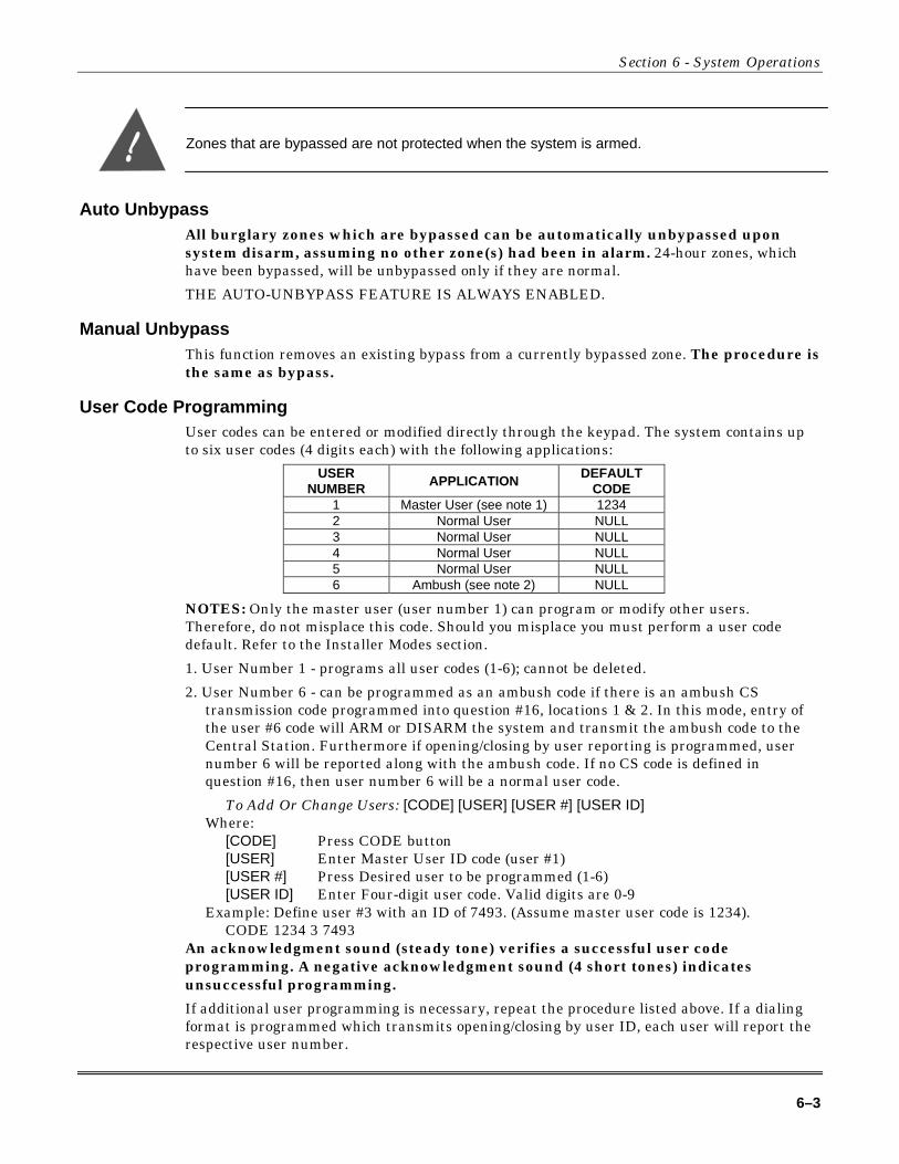
User Code ProgrammingUser codes can be entered or modified directly through the keypad. The system contains upto six user codes (4 digits each) with the following applications:
USERNUMBER APPLICATION
DEFAULTCODE
1 Master User (see note 1) 12342 Normal User NULL3 Normal User NULL4 Normal User NULL5 Normal User NULL6 Ambush (see note 2) NULL
NOTES: Only the master user (user number 1) can program or modify other users.Therefore, do not misplace this code. Should you misplace you must perform a user codedefault. Refer to the Installer Modes section.
1. User Number 1 - programs all user codes (1-6); cannot be deleted.
2. User Number 6 - can be programmed as an ambush code if there is an ambush CStransmission code programmed into question #16, locations 1 & 2. In this mode, entry ofthe user #6 code will ARM or DISARM the system and transmit the ambush code to theCentral Station. Furthermore if opening/closing by user reporting is programmed, usernumber 6 will be reported along with the ambush code. If no CS code is defined inquestion #16, then user number 6 will be a normal user code.
To Add Or Change Users: [CODE] [USER] [USER #] [USER ID]Where:
[CODE] Press CODE button[USER] Enter Master User ID code (user #1)[USER #] Press Desired user to be programmed (1-6)[USER ID] Enter Four-digit user code. Valid digits are 0-9
Example: Define user #3 with an ID of 7493. (Assume master user code is 1234).CODE 1234 3 7493
An acknowledgment sound (steady tone) verifies a successful user codeprogramming. A negative acknowledgment sound (4 short tones) indicatesunsuccessful programming.
If additional user programming is necessary, repeat the procedure listed above. If a dialingformat is programmed which transmits opening/closing by user ID, each user will report therespective user number.
XL-1S Hookup and Installation Instructions
6–4
User code programming can be ONLY performed while the system is DISARMED.
User DeletionUser codes (2 - 6) can be deleted directly through the keypad. Once deleted their values willbe null.
To Delete Users: [CODE] [USER] [USER #] [*]Where:
[CODE] Press CODE button[USER] Enter Master User ID code (user #1)[USER #] Press the desired user number being deleted (2-6).
NOTE: User # 1 cannot be deleted, but it can be changed.[*] Press the asterisk (*) button
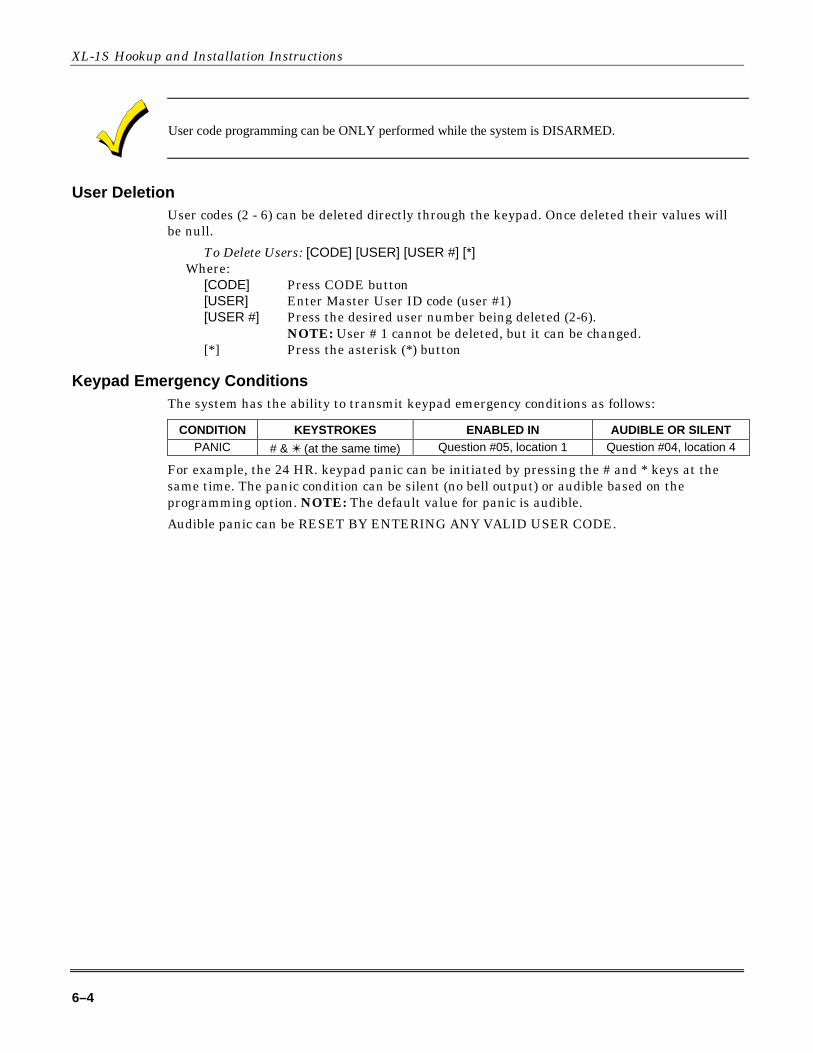
Keypad Emergency ConditionsThe system has the ability to transmit keypad emergency conditions as follows:
CONDITION KEYSTROKES ENABLED IN AUDIBLE OR SILENTPANIC # & ✴ (at the same time) Question #05, location 1 Question #04, location 4
For example, the 24 HR. keypad panic can be initiated by pressing the # and * keys at thesame time. The panic condition can be silent (no bell output) or audible based on theprogramming option. NOTE: The default value for panic is audible.
Audible panic can be RESET BY ENTERING ANY VALID USER CODE.

7–1
S E C T I O N 7
Installer Modes• • • • • • • • • • • • • • • • • • • • • • • • • • • • • • • • • • • • • • • • • • • • • • • • • •
TO ENTER INSTALLER MODE: [CODE][*][INSTALLER][X]
Where:[CODE] Press the CODE button[*] Press the asterisk (*) button[INSTALLER] Enter the 4 digit installer code (default = 2468)[X] Press the single digit indicating the installer mode as follows:
1 Installer Keypad ProgrammingPress 1 & 3 (at the same time) SYSTEM DEFAULTPress 7 & 9 (at the same time) USER CODE DEFAULT
Installer Mode 1 (Installer Keypad Programming)Enters the installer into keypad programming mode. Refer to the Keypad ProgrammingSection of this Manual. NOTE: There exists an option in the EZ-Mate Downloader Softwareto inhibit keypad programming. If selected, then a negative acknowledgment (4 short beeps)will be heard after attempting to enter this mode. The software has another option (DefaultLockout) to inhibit another installer from defaulting the panel and entering keypadprogramming. This prevents hostile account takeovers.
Installer Mode 1 (System Default)
Any of the system keypads (LED & LCD) can initiate a system default of the system bypressing the “1” and “3” keys at the same time, while in the programming mode. Thesystem will then default (revert to factory program values) and go through the resetsequence and THE SYSTEM WILL UNDERGO THE WARMUP TIME SEQUENCE. Asystem default can also be generated by removing power (AC & DC), shorting JP1 & JP2,reapplying power (with JP1 & JP2 still intact) waiting 8 seconds, and then removing shortwith power still applied. NOTE: A programming option can be selected through the EZ-MateDownloader Software known as Default Lockout. If selected, then a system default resetwill change all of the programmable options with the exception of the CSID (a code used bythe software to identify the panel during remote connections) and the installer code. Thisprevents hostile account takeovers.
Installer Mode 1 (User Code Default)
The user codes can be reset to factory default values (User Code 1 = 1234) by pressing the“7” and “9” keys at the same time, while in the programming mode. The user codes willdefault and the system will go through the reset sequence and THE SYSTEM WILLUNDERGO THE WARMUP TIME SEQUENCE.
Installer Mode 2 (System Log View)The system retains the past 2 alarm memory conditions; this can contain from 1 – 6 alarmsper arming cycle or up to 12 alarms for two arming cycles. LED keypads will display alarmsas fast blinking cone lights along with a fast blinking ready (RDY) light. In both keypadtypes (LCD and LED), the display will show the events starting from the oldest event.Pressing of the “#” key will advance the log to the most recent alarm in memory. To exit fromthe system log view mode press the “*” key. NOTE: as the log is advanced, the LCD keypadwill scroll through all zones that were in alarm for the event. The system log cannot becleared by the keypad. It can only be cleared by the Downloader Software. On LCD keypads
XL-1S Hookup and Installation Instructions
7–2
the following log cannot be cleared by the keypad. It can only be cleared by the DownloaderSoftware. On LCD keypads the following appears:
ALARM MEM: ZN1FRONT DOOR
TO EXIT THE SYSTEM LOG VIEW MODE: Press the asterisk key (*). However, if theasterisk key (*) does not exit, enter a valid user code.
Installer Mode 3 (Unattended Download)The Unattended Download function allows the installation of the control panel and thenhave the control panel dial the telephone number of CS downloading computer so that thecontrol panel can be downloaded without having the operator present. Basically, the CSdownloading computer telephone number will be programmed into the callback number(question 03) and an identification number (same as the account number in the downloadersoftware) will be programmed into the secondary telephone (question 02). NOTE: These aretemporary values since they will be reprogrammed after downloading.
Unattended Download requires the following sequence:
1. The PC operator must select UNATTENDED DOWNLOAD in the Downloader SoftwareMain Menu.
2. Enter Unattended Download mode: [CODE][*] [INSTALLER][3].
3. The system will now enter keypad programming at question 01. Enter the telephonenumber of the central station downloading computer. Enter [#] after each digit; forexample: [1] [#] [2] [#] [3] [#]. You can enter up to 12 digits. This phone number should bethe same as the CS callback number (question 03 from Keypad Programming if the panelis programmed for callback).
4. Go to programming question 02 by entering the sequence [*] [0] [2]. Enter the desiredaccount number, following each digit with [#]. This will be used by the CS downloadingcomputer to determine the proper account information to download to this subscriber. Theaccount number must be 6 digits in length and it is the downloaders account designatornot the account number that will be communicated to the receiver. For ID's less than 6digits long you must enter leading 0's to make the number 6 digits long. Example: for ID345 enter [0] [#] [0] [#] [0] [#] [3] [#] [4] [#] [5] [#].
5. Press the “STAY” key to exit Programming mode. The control panel will now dial thedownloading computer telephone number entered into the callback number. (If you havenot already selected the Unattended Communications option from the main menu of thedownloading computer, select it prior to continuing.) Upon connection with the computerthe customer account number programmed in step 3 will be obtained and the system willperform the desired download operation. NOTE: The CS downloading computer must bewaiting in the Unattended Communications option and preprogrammed with the accountinformation in order for the Unattended Download to be functional.
Installer Mode 4 (On-Line Download)In this mode, the installer can initiate a remote communications session with the CSDownloading computer at the control panel location. Typically, a remote communicationssession is initiated by the CS. On-line downloading allows the installer to call the office (fromthe same telephone line as the panel), discuss the action required and allow the CS operatorto complete the request while on-line. No additional telephone call is needed. On-lineconnection can be made as follows:
1. After completing the installation, attach a handset to the telco terminals (tip and ring) oruses the standard home telephone to dial the CS downloading modem telephone line.Connection is made with a person at the CS downloading computer and the account to be

Section 6 - System Operations
7–3
downloaded is verbally identified. The downloading computer operator selects “On-lineRemote Operations” from the Device menu.
2. Enter the on-line download sequence: [CODE] [*] [INSTALLER] [4] or use the end-usercommand of [#] [9], if enabled. This will cause the control panel to behave as if it receiveda request for a remote communications session, and to look for the standard panel to CSprotocol.
3. Once the standard connection is made, the necessary remote communications sessions cantake place (Upload, Download, and Remote commands).
4. Hang up the telephone or remove headset from the line to prevent interference that mayaffect upload/download data. The downloader software will automatically terminate theconnection after remote communications end.

XL-1S Hookup and Installation Instructions
7–4

8–1
S E C T I O N 8
System Programming• • • • • • • • • • • • • • • • • • • • • • • • • • • • • • • • • • • • • • • • • • • • • • • • • •
GeneralThe system can be programmed in any one of the following methods:
• Directly through keypad (XK-104 or 6805)
• EZ-MATE PC DOWNLOADER model 7700 remotely
NOTE: The EZ-Mate downloader has not been tested for UL applications.
This manual describes system programming via the keypad. The other programming devicesinclude documentation describing their programming procedures.
Keypad programming is accomplished by understanding and completing thePROGRAMMING SHEET located in the back of this manual.
There are 20 total programming questions numbered 00-19.
Within each question there are several locations labeled L1, L2, etc. for data entry.
The system is shipped from the factory with SPECIFIC DEFAULT VALUES that wereselected for a typical installation. If the default values are suitable for your installation thenprogramming can be simplified. The default values are listed with each programmingquestion and in the SYSTEM DEFAULT section of this manual.
Programming QuestionsThis portion of the manual defines the programming questions along with the valuesexpected for each question. BEFORE USING THE PROGRAMMING SHEET, FILL THESYSTEM PLANNING WORKSHEETS AT THE END OF THIS MANUAL. Then,Complete the Programming sheet and then enter the data through the keypad asexplained in the section titled Data Entry Through the Keypad. DO NOT ATTEMPTTO ENTER DATA BEFORE COMPLETELY FILLING OUT PROGRAM SHEET.
QUESTION 01PRIMARY TELEPHONE NUMBER DEFAULT = 234AAAAAAAAA
Enter the telephone number (including area code and/or dialing prefix IF NECESSARY) ofthe primary central station receiver in L1 - L12. Enter the valid digits from the table below.
Digit FUNCTION COMMENTS0-9 0-9A Signifies end of the phone number Enter after last digit of phone numberB Asterisk (✴) Enter whenever the asterisk is usedC 3 Second pause Provides delay to wait for dial toneD Pound (#) Enter whenever the pound is usedE ✴70C (Touch-tone) ✴ 1170C (Rotary) Enter to disable Call WaitingF 800 Enter whenever the "800" prefix is needed
REPORTING ROUTE:The system will report all signals to the primary receiver phone number. The panel willalternate between the primary and secondary receivers (if the second phone number isprogrammed) for a maximum of 8 attempts each until the signal has been acknowledged.

XL-1S Hookup and Installation Instructions
8–2
QUESTION 02SECONDARY TELEPHONE NUMBER DEFAULT = AAAAAAAAAAAA
Enter the telephone number (including area code and/or dialing prefix IF NECESSARY) ofthe secondary central station receiver in L1 - L12.
Enter the valid digits from the table in question 01. The secondary telephone number will beused if the panel is unable to reach the Central Station via the primary number. This isknown as BACKUP reporting. If the SPLIT REPORTING feature is programmed, thenOPENING and CLOSING signals will be directed to the secondary CS number only, while allother conditions will be reported to the primary number.
If neither split nor backup reporting is necessary then this question may be left as factorydefaulted and all conditions will be routed to the Primary Telephone number only.
QUESTION 03CALLBACK TELEPHONE NUMBER DEFAULT = AAAAAAAAAAAA
Enter the telephone number (including area code and/or dialing prefix if necessary) for thiscontrol panel to reach the callback location. The callback number is the optional location ofthe EZ-Mate Downloader where the control panel will call during a remote communications(upload/download etc) session. During remote communications the programming device andthe control panel will first confirm the CS security code. If valid, communications can begin.If a callback number is defined, the control panel will the hang up and dial the callbacknumber. Enter the valid digits from the table in question 01. NOTE: For no callbackcapability enter AAAAAAAAAAAA.
QUESTION 04DIALER OPTIONS DEFAULT = 1601
There are 4 locations (L1-L4) within this question which define various dialer and systemoptions as follows:
Question 04, L1Dialer Formats DEFAULT = 1
Enter the digit for the desired dialer format from the table below in location L1. NOTE: Thecheckmark highlights which options are selected.
DIALING FORMATDigit
PULSE TOUCH-TONECS REPORTING FORMAT
0 9 STANDARD OR 4X21 9 STANDARD OR 4X28 DIALER DISABLE LOCAL ALARM ONLY
NOTE: See Question #04,location 3 to select specificCS Reporting FormatMessage Length andspecific Dialing Pulse Type.
If Local Alarm is desired, then no other options need to be disabled (Telephone #, CS Codes).
Question 04, L2CS Receiver Type Default = 6
Enter the digit for the desired receiver type from the table below in location L2. NOTE: Thecheckmark highlights which options are selected.
FORMAT PULSE SPEED HANDSHAKE FREQUENCYDigit
10 PPS 20 PPS 40 PPS 1400 HZ 2300 HZ PARITYTYPICAL CS RECEIVER
0 9 9 FBI, ADEMCO, SILENT KNIGHT1 9 9 9 FBI2 9 9 FBI3 9 9 9 FBI
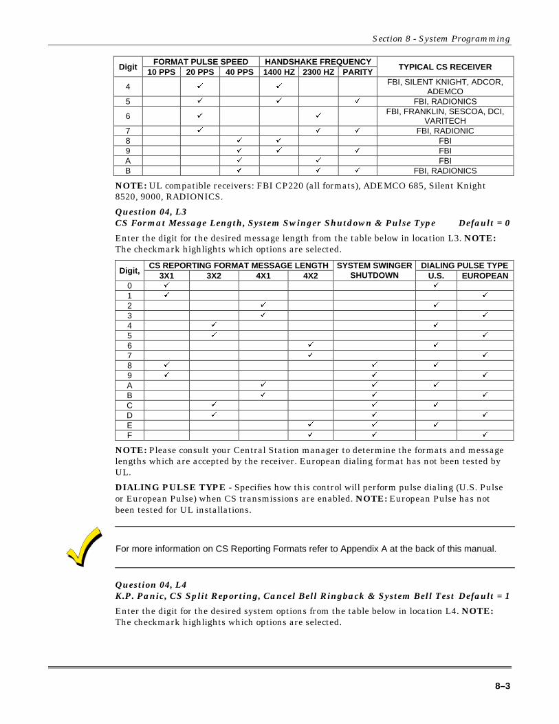
Section 8 - System Programming
8–3
FORMAT PULSE SPEED HANDSHAKE FREQUENCYDigit
10 PPS 20 PPS 40 PPS 1400 HZ 2300 HZ PARITYTYPICAL CS RECEIVER
4 9 9FBI, SILENT KNIGHT, ADCOR,
ADEMCO5 9 9 9 FBI, RADIONICS
6 9 9FBI, FRANKLIN, SESCOA, DCI,
VARITECH7 9 9 9 FBI, RADIONIC8 9 9 FBI9 9 9 9 FBIA 9 9 FBIB 9 9 9 FBI, RADIONICS
NOTE: UL compatible receivers: FBI CP220 (all formats), ADEMCO 685, Silent Knight8520, 9000, RADIONICS.
Question 04, L3CS Format Message Length, System Swinger Shutdown & Pulse Type Default = 0
Enter the digit for the desired message length from the table below in location L3. NOTE:The checkmark highlights which options are selected.
CS REPORTING FORMAT MESSAGE LENGTH DIALING PULSE TYPEDigit,
3X1 3X2 4X1 4X2SYSTEM SWINGER
SHUTDOWN U.S. EUROPEAN0 9 9
1 9 9
2 9 9
3 9 9
4 9 9
5 9 9
6 9 9
7 9 9
8 9 9 9
9 9 9 9
A 9 9 9
B 9 9 9
C 9 9 9
D 9 9 9
E 9 9 9
F 9 9 9
NOTE: Please consult your Central Station manager to determine the formats and messagelengths which are accepted by the receiver. European dialing format has not been tested byUL.
DIALING PULSE TYPE - Specifies how this control will perform pulse dialing (U.S. Pulseor European Pulse) when CS transmissions are enabled. NOTE: European Pulse has notbeen tested for UL installations.
For more information on CS Reporting Formats refer to Appendix A at the back of this manual.
Question 04, L4K.P. Panic, CS Split Reporting, Cancel Bell Ringback & System Bell Test Default = 1
Enter the digit for the desired system options from the table below in location L4. NOTE:The checkmark highlights which options are selected.
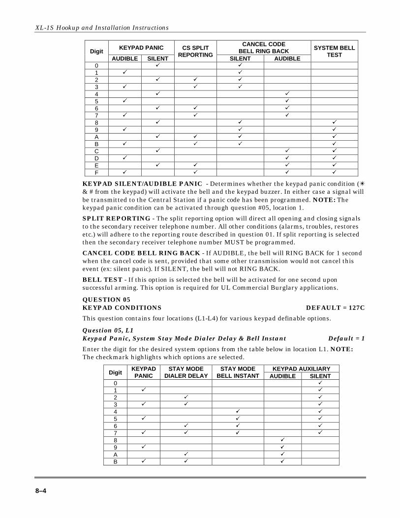
XL-1S Hookup and Installation Instructions
8–4
KEYPAD PANICCANCEL CODE
BELL RING BACKDigitAUDIBLE SILENT
CS SPLITREPORTING
SILENT AUDIBLE
SYSTEM BELLTEST
0 9 9
1 9 9
2 9 9 9
3 9 9 9
4 9 9
5 9 9
6 9 9 9
7 9 9 9
8 9 9 9
9 9 9 9
A 9 9 9 9
B 9 9 9 9
C 9 9 9
D 9 9 9
E 9 9 9 9
F 9 9 9 9
KEYPAD SILENT/AUDIBLE PANIC - Determines whether the keypad panic condition (✴& # from the keypad) will activate the bell and the keypad buzzer. In either case a signal willbe transmitted to the Central Station if a panic code has been programmed. NOTE: Thekeypad panic condition can be activated through question #05, location 1.
SPLIT REPORTING - The split reporting option will direct all opening and closing signalsto the secondary receiver telephone number. All other conditions (alarms, troubles, restoresetc.) will adhere to the reporting route described in question 01. If split reporting is selectedthen the secondary receiver telephone number MUST be programmed.
CANCEL CODE BELL RING BACK - If AUDIBLE, the bell will RING BACK for 1 secondwhen the cancel code is sent, provided that some other transmission would not cancel thisevent (ex: silent panic). If SILENT, the bell will not RING BACK.
BELL TEST - If this option is selected the bell will be activated for one second uponsuccessful arming. This option is required for UL Commercial Burglary applications.
QUESTION 05KEYPAD CONDITIONS DEFAULT = 127C
This question contains four locations (L1-L4) for various keypad definable options.
Question 05, L1Keypad Panic, System Stay Mode Dialer Delay & Bell Instant Default = 1
Enter the digit for the desired system options from the table below in location L1. NOTE:The checkmark highlights which options are selected.
KEYPAD AUXILIARYDigit
KEYPADPANIC
STAY MODEDIALER DELAY
STAY MODEBELL INSTANT AUDIBLE SILENT
0 9
1 9 9
2 9 9
3 9 9 9
4 9 9
5 9 9 9
6 9 9 9
7 9 9 9 9
8 9
9 9 9
A 9 9
B 9 9 9
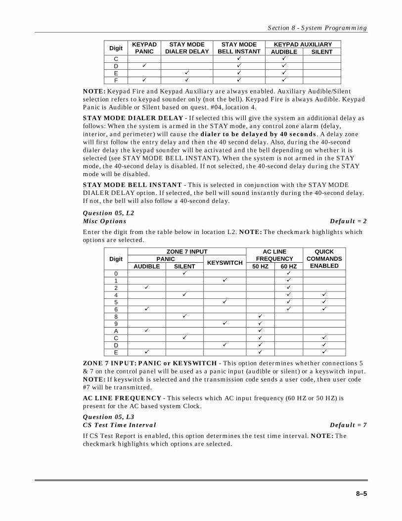
Section 8 - System Programming
8–5
KEYPAD AUXILIARYDigit
KEYPADPANIC
STAY MODEDIALER DELAY
STAY MODEBELL INSTANT AUDIBLE SILENT
C 9 9
D 9 9 9
E 9 9 9
F 9 9 9 9
NOTE: Keypad Fire and Keypad Auxiliary are always enabled. Auxiliary Audible/Silentselection refers to keypad sounder only (not the bell). Keypad Fire is always Audible. KeypadPanic is Audible or Silent based on quest. #04, location 4.
STAY MODE DIALER DELAY - If selected this will give the system an additional delay asfollows: When the system is armed in the STAY mode, any control zone alarm (delay,interior, and perimeter) will cause the dialer to be delayed by 40 seconds. A delay zonewill first follow the entry delay and then the 40 second delay. Also, during the 40-seconddialer delay the keypad sounder will be activated and the bell depending on whether it isselected (see STAY MODE BELL INSTANT). When the system is not armed in the STAYmode, the 40-second delay is disabled. If not selected, the 40-second delay during the STAYmode will be disabled.
STAY MODE BELL INSTANT - This is selected in conjunction with the STAY MODEDIALER DELAY option. If selected, the bell will sound instantly during the 40-second delay.If not, the bell will also follow a 40-second delay.
Question 05, L2Misc Options Default = 2
Enter the digit from the table below in location L2. NOTE: The checkmark highlights whichoptions are selected.
ZONE 7 INPUTPANIC
AC LINEFREQUENCYDigit
AUDIBLE SILENTKEYSWITCH
50 HZ 60 HZ
QUICKCOMMANDS
ENABLED0 9 9
1 9 9
2 9 9
4 9 9 9
5 9 9 9
6 9 9 9
8 9 9
9 9 9
A 9 9
C 9 9 9
D 9 9 9
E 9 9 9
ZONE 7 INPUT: PANIC or KEYSWITCH - This option determines whether connections 5& 7 on the control panel will be used as a panic input (audible or silent) or a keyswitch input.NOTE: If keyswitch is selected and the transmission code sends a user code, then user code#7 will be transmitted.
AC LINE FREQUENCY - This selects which AC input frequency (60 HZ or 50 HZ) ispresent for the AC based system Clock.
Question 05, L3CS Test Time Interval Default = 7
If CS Test Report is enabled, this option determines the test time interval. NOTE: Thecheckmark highlights which options are selected.
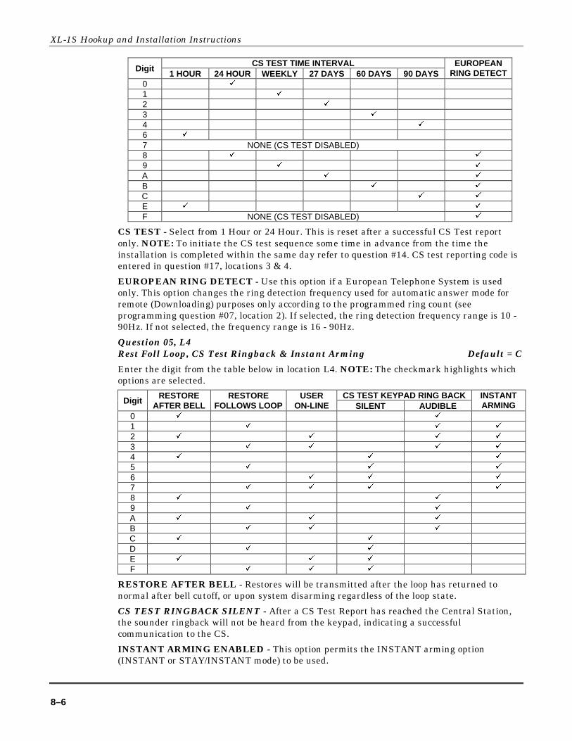
XL-1S Hookup and Installation Instructions
8–6
CS TEST TIME INTERVALDigit
1 HOUR 24 HOUR WEEKLY 27 DAYS 60 DAYS 90 DAYSEUROPEAN
RING DETECT0 9
1 9
2 9
3 9
4 9
6 9
7 NONE (CS TEST DISABLED)8 9 9
9 9 9
A 9 9
B 9 9
C 9 9
E 9 9
F NONE (CS TEST DISABLED) 9
CS TEST - Select from 1 Hour or 24 Hour. This is reset after a successful CS Test reportonly. NOTE: To initiate the CS test sequence some time in advance from the time theinstallation is completed within the same day refer to question #14. CS test reporting code isentered in question #17, locations 3 & 4.
EUROPEAN RING DETECT - Use this option if a European Telephone System is usedonly. This option changes the ring detection frequency used for automatic answer mode forremote (Downloading) purposes only according to the programmed ring count (seeprogramming question #07, location 2). If selected, the ring detection frequency range is 10 -90Hz. If not selected, the frequency range is 16 - 90Hz.
Question 05, L4Rest Foll Loop, CS Test Ringback & Instant Arming Default = C
Enter the digit from the table below in location L4. NOTE: The checkmark highlights whichoptions are selected.
CS TEST KEYPAD RING BACKDigit
RESTOREAFTER BELL
RESTOREFOLLOWS LOOP
USERON-LINE SILENT AUDIBLE
INSTANTARMING
0 9 9
1 9 9 9
2 9 9 9 9
3 9 9 9 9
4 9 9 9
5 9 9 9
6 9 9 9
7 9 9 9 9
8 9 9
9 9 9
A 9 9 9
B 9 9 9
C 9 9
D 9 9
E 9 9 9
F 9 9 9
RESTORE AFTER BELL - Restores will be transmitted after the loop has returned tonormal after bell cutoff, or upon system disarming regardless of the loop state.
CS TEST RINGBACK SILENT - After a CS Test Report has reached the Central Station,the sounder ringback will not be heard from the keypad, indicating a successfulcommunication to the CS.
INSTANT ARMING ENABLED - This option permits the INSTANT arming option(INSTANT or STAY/INSTANT mode) to be used.
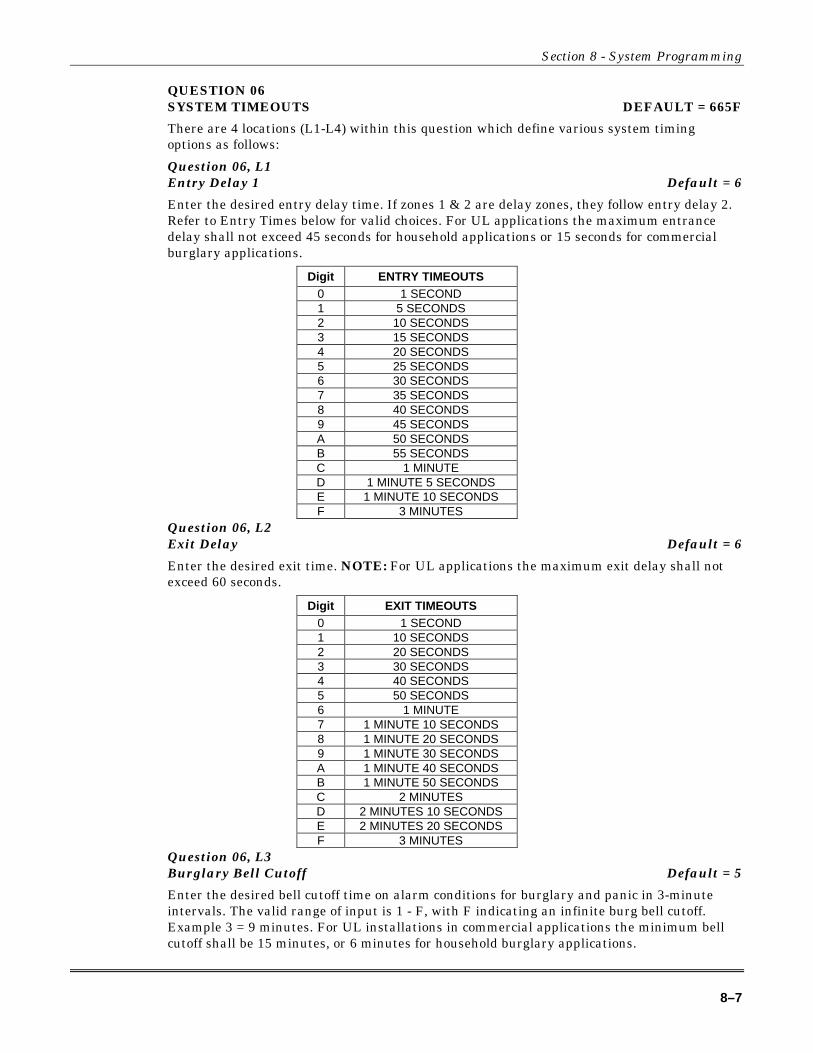
Section 8 - System Programming
8–7
QUESTION 06SYSTEM TIMEOUTS DEFAULT = 665F
There are 4 locations (L1-L4) within this question which define various system timingoptions as follows:
Question 06, L1Entry Delay 1 Default = 6
Enter the desired entry delay time. If zones 1 & 2 are delay zones, they follow entry delay 2.Refer to Entry Times below for valid choices. For UL applications the maximum entrancedelay shall not exceed 45 seconds for household applications or 15 seconds for commercialburglary applications.
Digit ENTRY TIMEOUTS0 1 SECOND1 5 SECONDS2 10 SECONDS3 15 SECONDS4 20 SECONDS5 25 SECONDS6 30 SECONDS7 35 SECONDS8 40 SECONDS9 45 SECONDSA 50 SECONDSB 55 SECONDSC 1 MINUTED 1 MINUTE 5 SECONDSE 1 MINUTE 10 SECONDSF 3 MINUTES
Question 06, L2Exit Delay Default = 6
Enter the desired exit time. NOTE: For UL applications the maximum exit delay shall notexceed 60 seconds.
Digit EXIT TIMEOUTS0 1 SECOND1 10 SECONDS2 20 SECONDS3 30 SECONDS4 40 SECONDS5 50 SECONDS6 1 MINUTE7 1 MINUTE 10 SECONDS8 1 MINUTE 20 SECONDS9 1 MINUTE 30 SECONDSA 1 MINUTE 40 SECONDSB 1 MINUTE 50 SECONDSC 2 MINUTESD 2 MINUTES 10 SECONDSE 2 MINUTES 20 SECONDSF 3 MINUTES
Question 06, L3Burglary Bell Cutoff Default = 5
Enter the desired bell cutoff time on alarm conditions for burglary and panic in 3-minuteintervals. The valid range of input is 1 - F, with F indicating an infinite burg bell cutoff.Example 3 = 9 minutes. For UL installations in commercial applications the minimum bellcutoff shall be 15 minutes, or 6 minutes for household burglary applications.

XL-1S Hookup and Installation Instructions
8–8
DigitBURGLARY & FIRE BELL
TIMEOUTS1 3 MINUTES2 6 MINUTES3 9 MINUTES4 12 MINUTES5 15 MINUTES6 18 MINUTES7 21 MINUTES8 24 MINUTES9 27 MINUTESA 30 MINUTESB 33 MINUTESC 36 MINUTESD 39 MINUTESE 42 MINUTESF INFINITE
Question 06, L4Fire Bell Cutoff Default = F
Enter the desired bell cutoff time for fire conditions in three-minute intervals. The validrange of input is 1 - F, with F indicating an infinite fire bell cutoff. Example 3 = 9 minutes.For UL installations the minimum fire bell cutoff time shall be 6 minutes.
QUESTION 07MISCELLANEOUS SYSTEM OPTIONS DEFAULT = 2705
There are 4 locations (L1-L4) within this question which define various system timingoptions as follows:
Question 07, L1Entry Delay 2 Default = 2
Enter the desired entry delay time. Refer to Entry Times in question #6, L1 for valid choices.If zones 3 & 4 are delay zones, they follow entry delay 2. For UL applications, the maximumentrance delay shall not exceed 45 seconds for household applications or 15 seconds forcommercial burglary applications.
Question 07, L2Ring Count & System Dialer Delay Default = 7
Enter the digit from the table below in location L2. NOTE: The checkmark highlights whichoptions are selected.
DigitREMOTE COMMUNICATIONS
RING COUNTSYSTEM
DIALER DELAYTRANSMIT ZONE
RESTORE0 NONE (REMOTE COMM. DISABLED)1 4 RINGS2 8 RINGS3 12 RINGS4 NONE (REMOTE COMM. DISABLED) 9
5 4 RINGS 9
6 8 RINGS 9
7 12 RINGS 9
8 NONE (REMOTE COMM. DISABLED) 9
9 4 RINGS 9
A 8 RINGS 9
B 12 RINGS 9
C NONE (REMOTE COMM. DISABLED) 9 9
D 4 RINGS 9 9
E 8 RINGS 9 9
F 12 RINGS 9 9
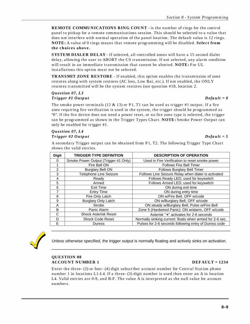
Section 8 - System Programming
8–9
REMOTE COMMUNICATIONS RING COUNT - is the number of rings for the controlpanel to pickup for a remote communications session. This should be selected to a value thatdoes not interfere with normal operation of the panel location. The default value is 12 rings.NOTE: A value of 0 rings means that remote programming will be disabled. Select fromthe choices above.
SYSTEM DIALER DELAY - If selected, all controlled zones will have a 15 second dialerdelay, allowing the user to ABORT the CS transmission. If not selected, any alarm conditionwill result in an immediate transmission that cannot be aborted. NOTE: For ULinstallations this option must not be selected.
TRANSMIT ZONE RESTORE - If enabled, this option enables the transmission of zonerestores along with system restores (AC loss, Low Bat, etc.). If not enabled, the ONLYrestores transmitted will be the system restores (see question #18, location 2.
Question 07, L3Trigger #1 Output Default = 0
The smoke power terminals (12 & 13) or P1, T1 can be used as trigger #1 output. If a firezone requiring fire verification is used in the system, the trigger should be programmed as“0”. If the fire device does not need a power reset, or no fire zone type is selected, the triggercan be programmed as shown in the Trigger Types Chart. NOTE: Smoke Power Output canonly be enabled for trigger #1.
Question 07, L4Trigger #2 Output Default = 5
A secondary Trigger output can be obtained from P1, T2. The following Trigger Type Chartshows the valid entries.
Digit TRIGGER TYPE DEFINITION DESCRIPTION OF OPERATION0 Smoke Power Output (Trigger #1 Only) Used in Fire Verification to reset smoke power1 Fire Bell ON Follows Fire Bell Timer2 Burglary Bell ON Follows Burglary Bell Timer3 Telephone Line Seizure Follows Line Seizure Relay when dialer is activated4 Ready Follows Ready LED; used for keyswitch5 Armed Follows Armed LED; used for keyswitch6 Exit Time ON during exit time7 Entry Time ON during entry time8 Fire Only Latch ON w/Fire Bell, OFF w/code9 Burglary Only Latch ON w/Burglary Bell, OFF w/codeA Strobe ON steady w/Burglary Bell, Pulse w/Fire BellB Panic Alarm Zone 5 (Hardwired Panic): ON w/alarm, OFF w/codeC Shock Asterisk Reset Asterisk "✴" activates for 2-6 secondsD Shock Code Reset Normally sinking current: floats when armed for 2-6 sec.E Duress Pulses for 2-6 seconds following entry of Duress code
Unless otherwise specified, the trigger output is normally floating and actively sinks on activation.
QUESTION 08ACCOUNT NUMBER 1 DEFAULT = 1234
Enter the three- (3) or four- (4) digit subscriber account number for Central Station phonenumber 1 in locations L1-L4. If a three- (3) digit number is used then enter an A in locationL4. Valid entries are 0-9, and B-F. The value A is interpreted as the null value for accountnumbers.

XL-1S Hookup and Installation Instructions
8–10
QUESTION 09ACCOUNT NUMBER 2 DEFAULT = AAAA
Enter the three- (3) or four- (4) digit subscriber account number for Central Station phonenumber 2 in locations L1-L4. If a three- (3) digit number is used then enter an A in locationL4. Valid entries are 0-9, and B-F. The value A is interpreted as the null value for accountnumbers. If the second phone number is not used this question can be left as factorydefaulted.
THIS ACCOUNT NUMBER MUST BE ENTERED IF YOU HAVE PROGRAMMED ASECOND RECEIVER PHONE NUMBER FOR BACKUP OR SPLIT REPORTING.
Zone ProgrammingQuestions 10-13 represent all the options related to programmable zones 1-4. Each questioncontains four (4) locations L1-L4. The first two locations (L1 & L2) define the zone type andoptions. The second two locations (L3 & L4) define the alarm code transmitted to the CentralStation for that zone.
Zone Types
Zones 1-4 can be programmed for any one of the following zone types:
BURGLARY (CONTROLLED) ZONESZONE TYPE ZONE OPTIONSL1L2
Digits INSTANT(PERIMETER)
DELAY(EXIT/ENTRY)
INTERIORFOLLOWER CHIME DAY
BYPASSIN STAY
FASTZONE
10 9 NONE(INSTANT ZONE W/O OPTIONS)11 9 9
12 9 9
13 9 9 9
14 9 9
15 9 9 9
18 9 9
19 9 9 9
1A 9 9 9
1B 9 9 9 9
1C 9 9 9
1D 9 9 9 9
20 9 NONE (DELAY ZONE W/O OPTIONS)21 9 9
24 9 9
25 9 9 9
40 9 NONE (INTERIOR ZONE W/O OPTIONS)41 9 9
44 9 9
45 9 9 9
48 9 9
49 9 9 9
4C 9 9 9
4D 9 9 9
Burglary (Controlled) Zones
DELAY - This is the industry standard exit/entry zone. When the system is armed exit timebegins. After exit expires, any subsequent violation of this zone will begin entry time. If thesystem is not disarmed within the programmed entry time an alarm will occur. The keypadsounder will annunciate steadily during entry time, unless there had been an alarmcondition, at which time it will pulse. Delay zones will activate instantly when the system isarmed using the STAY/INSTANT mode if enabled. Delay zones employ the Exit ErrorWarning feature described in the note below.
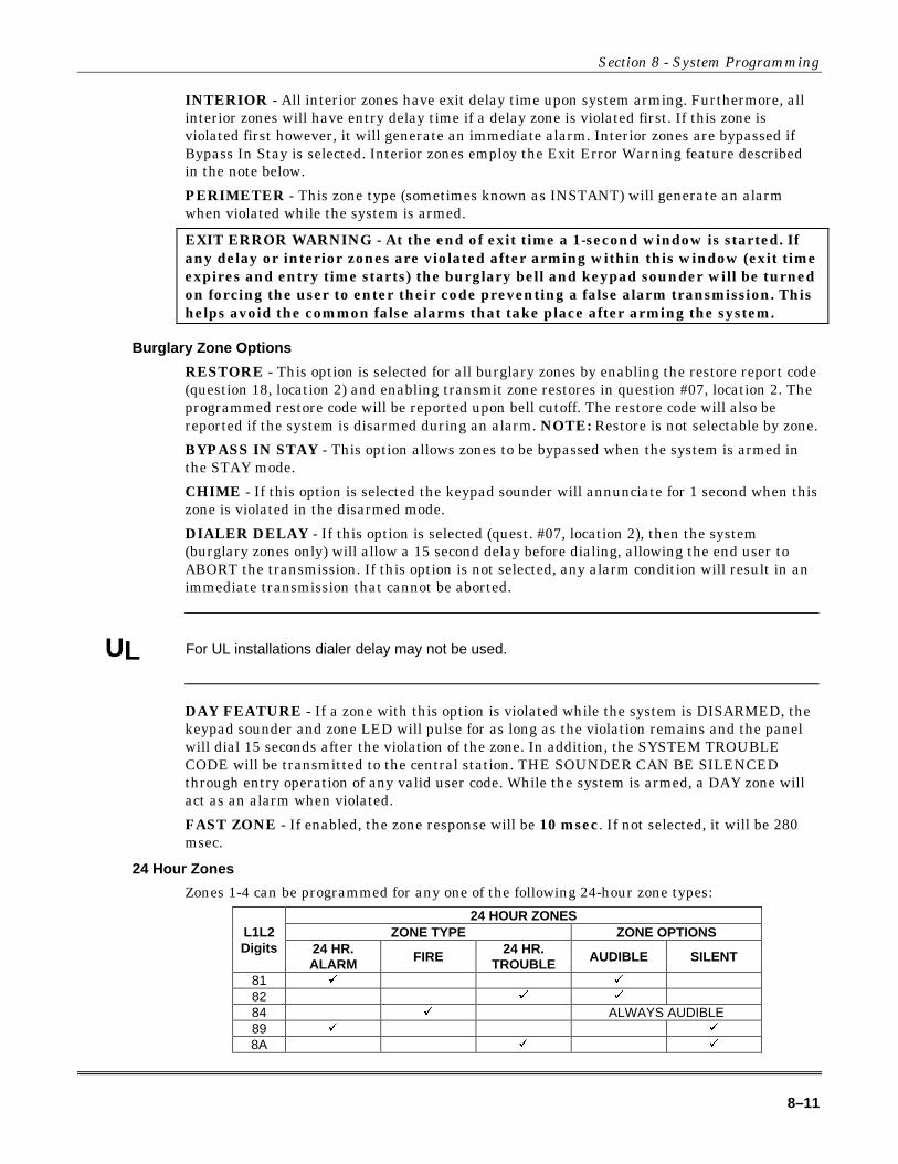
Section 8 - System Programming
8–11
INTERIOR - All interior zones have exit delay time upon system arming. Furthermore, allinterior zones will have entry delay time if a delay zone is violated first. If this zone isviolated first however, it will generate an immediate alarm. Interior zones are bypassed ifBypass In Stay is selected. Interior zones employ the Exit Error Warning feature describedin the note below.
PERIMETER - This zone type (sometimes known as INSTANT) will generate an alarmwhen violated while the system is armed.
EXIT ERROR WARNING - At the end of exit time a 1-second window is started. Ifany delay or interior zones are violated after arming within this window (exit timeexpires and entry time starts) the burglary bell and keypad sounder will be turnedon forcing the user to enter their code preventing a false alarm transmission. Thishelps avoid the common false alarms that take place after arming the system.
Burglary Zone Options
RESTORE - This option is selected for all burglary zones by enabling the restore report code(question 18, location 2) and enabling transmit zone restores in question #07, location 2. Theprogrammed restore code will be reported upon bell cutoff. The restore code will also bereported if the system is disarmed during an alarm. NOTE: Restore is not selectable by zone.
BYPASS IN STAY - This option allows zones to be bypassed when the system is armed inthe STAY mode.
CHIME - If this option is selected the keypad sounder will annunciate for 1 second when thiszone is violated in the disarmed mode.
DIALER DELAY - If this option is selected (quest. #07, location 2), then the system(burglary zones only) will allow a 15 second delay before dialing, allowing the end user toABORT the transmission. If this option is not selected, any alarm condition will result in animmediate transmission that cannot be aborted.
UL For UL installations dialer delay may not be used.
DAY FEATURE - If a zone with this option is violated while the system is DISARMED, thekeypad sounder and zone LED will pulse for as long as the violation remains and the panelwill dial 15 seconds after the violation of the zone. In addition, the SYSTEM TROUBLECODE will be transmitted to the central station. THE SOUNDER CAN BE SILENCEDthrough entry operation of any valid user code. While the system is armed, a DAY zone willact as an alarm when violated.
FAST ZONE - If enabled, the zone response will be 10 msec. If not selected, it will be 280msec.
24 Hour Zones
Zones 1-4 can be programmed for any one of the following 24-hour zone types:
24 HOUR ZONESZONE TYPE ZONE OPTIONSL1L2
Digits 24 HR.ALARM FIRE
24 HR.TROUBLE AUDIBLE SILENT
81 9 9
82 9 9
84 9 ALWAYS AUDIBLE89 9 9
8A 9 9
XL-1S Hookup and Installation Instructions
8–12
FIRE - FIRE zones on the system contain Fire Verification Logic. Upon detection of the firstviolation, smoke detector power will be reset for a period of 8 seconds. After this time period,power is restored. For a period of 5 seconds the fire zone will not be scanned allowing thesmoke detectors to settle. Future violations within a two-minute period will result in aPULSING BELL OUTPUT, RAPID PULSING ZONE LED, and IMMEDIATE transmissionto the CS. Fire signals cannot be aborted.
Entry of any valid user code will silence the sounder, bell and reset smoke detector power. Ifthe system detects that the fire zone is still violated within 2 minutes of power reset, thezone LED will pulse slowly to indicate a fire trouble. Thereafter, smoke detector power willbe reset every 4 minutes automatically in an attempt to clear the fire zone.
In the event the fire zone experiences an open, the system indicates fire trouble by pulsingthe keypad zone LED and sounder slowly. The system trouble code (followed by the zonecode) will be reported to the CS.
The keypad sounder can be SILENCED through entry of ANY VALID USER CODE. NOTE:FIRE ZONES cannot be bypassed. ZONE 4 CAN BE PROGRAMMED AS A FIRE ZONEFOR BELL SUPERVISION.
24 HR. ALARM - This zone type is always active, independent of the system arming status.Programming options include audible (STEADY BELL) or silent (NO BELL or keypadindications). Upon violation the zone LEDs will pulse rapidly (audible zones only) and animmediate CS transmission will occur which cannot be aborted.
24 Hour Alarm zones can be bypassed, however they cannot be unbypassed if a violationexists on the zone terminals.
24 HR. TROUBLE - This zone type is always active, independent of the system armingstatus. Programming options include audible (PULSING KEYPAD SOUNDER) or silent.Upon violation the zone LED will pulse slowly. Trouble condition must exist for 15 secondsbefore a transmission will occur. The keypad display and sounder will clear upon zonerestoral.
24 Hour Trouble zones can be bypassed, however they cannot be unbypassed if a violationexists on the zone terminals.
24-hour trouble is not to be used for fire and burglary detection zones. 24-Hour silent alarm zonesare not to be used for perimeter protection. THE SOUNDER MAY BE SILENCED THROUGHENTRY OF ANY VALID USER CODE.
WARNING: Fire Zones CANNOT BE BYPASSED. 24 Hour zones CAN BEBYPASSED, however, they CANNOT BE UNBYPASSED if a violation exists on theirterminals.
Zone Alarm Codes
As previously specified locations L3 and L4 of the zone questions represent the alarm codethat will be reported to the central station.
Zones will transmit to the Central Station unless these digits are defined as AA for any individualzone, or the local dialer option is selected for all zones in question #04, location 1.
Based on the dialer format selected enter the alarm code as follows:
STANDARD FORMAT (3X1 or 4X1): Enter the desired single digit alarm code in locationL3 for the specific zone. The value placed in L4 will not be used.
Section 8 - System Programming
8–13
4x2: Enter the desired first digit of the alarm code in location L3 and the second digit in L4for the specific zone. Both digits will be used for all transmissions.
For more information on CS Reporting Formats refer to Appendix A at the back of this manual.
QUESTIONS 10 - 13 ZONES 1 - 4
There are 4 locations (L1-L4) within each of these questions which define the operation of thezones. Enter a 2-digit number in locations L1 and L2 from the zone chart for the desired typefor this zone. Enter the desired alarm code in locations L3 and L4 for this zone relative to thedialer format selected.
QUESTION 10ZONE 1 TYPE & CS CODE DEFAULT = 2031
Question 10, L1 & L2 - Zone 1 Type Default = 20Question 10, L3 & L4 - CS Code for Zone 1 Default = 31Zone 1 = Delay (Entry/Exit) w/CS reporting code = 31
QUESTION 11ZONE 2 TYPE & CS CODE DEFAULT = 4132
Question 11, L1 & L2 - Zone 2 Type Default = 41Question 11, L3 & L4 - CS Code for Zone 2 Default = 32Zone 2 = Interior Follower w/CS reporting code = 32
QUESTION 12ZONE 3 TYPE & CS CODE DEFAULT = 1033
Question 12, L1 & L2 - Zone 3 Type Default = 10Question 12, L3 & L4 - CS Code for Zone 3 Default = 33Zone 3 = Instant (Perimeter) w/CS reporting code = 33
QUESTION 13ZONE 4 TYPE & CS CODE DEFAULT = 1034
Question 13, L1 & L2 - Zone 4 Type Default = 10Question 13, L3 & L4 - CS Code for Zone 4 Default = 34Zone 4 = Instant (Perimeter) w/CS reporting code = 34
If zones 3 & 4 are programmed as DELAY zones, they follow ENTRY DELAY #2. If zone 4 isprogrammed as a FIRE zone, Bell Supervision is enabled. See Bell Output Terminal connectionsfor description.
QUESTION 14CS TEST OFFSET DEFAULT = 083B
There are 4 locations L1-L4 in this question.
Question 14, L1 & L2 - CS Test Offset Hours Default = 08Question 14, L3 & L4 - CS Test Offset Minutes Default = 3B
This option allows the installer to initiate the automatic CS Test sequence some time inadvance from the time the installation is completed within the same day. For example, if theinstallation is completed at 6:00 PM and the test is desired at 1:00 PM, then program an

XL-1S Hookup and Installation Instructions
8–14
offset of 7 hours. Enter hours and minutes in hexadecimal. The valid range for hours is 01 -18 (24 hours) and the valid range for minutes is 01 - 3C (60 minutes).
QUESTION 15CS CODES for AMBUSH and AC LOSS DEFAULT = AAAA
There are 4 locations L1-L4 in this question as follows:
Question 15, L1 & L2 - Ambush Code Default = AAIf an ambush code is defined, then user number 6 is the ambush code. The same rulesapply here regarding dialer format. If transmission is not desired, then program AA inlocations L1 & L2. NOTE: AMBUSH transmissions are immediate and not abortable.
Question 15, L3 & L4 - AC Loss Code Default = AAThe same rules apply here regarding dialer format. If transmission is not desired, thenprogram AA in locations L3 & L4. NOTE: AC LOSS is reported 15 minutes afterdetection.
QUESTION 16CS CODES for PANIC and LOW BATTERY DEFAULT = 22AA
There are 4 locations L1-L4 in this question.
Question 16, L1 & L2 - Panic Code Default = 22The same rules for programming regarding dialer format apply here. If transmissions arenot desired, then program AA in locations L1 & L2. NOTE: PANIC transmissions areimmediate and not abortable.
Question 16, L3 & L4 - Low Battery Code Default = AAThe same rules for programming regarding dialer format apply here. If transmissions arenot desired, then program AA in locations L3 & L4. LOW BATTERY transmissions willbe reported 4 minutes after detection. LOW BATTERY RESTORE CODE will be reportedWITHIN 4 minutes after detection of GOOD BATTERY condition.
QUESTION 17CS CODES for OPEN/CLOSE and CS TEST DEFAULT = AAAA
There are 4 locations L1-L4 in this question.
Question 17, L1 - Opening Code Default = AQuestion 17, L2 - Closing Code Default = AL1 is the single digit OPENING CODE. L2 is the single digit CLOSING CODE. Entry ofAA into these two locations means that openings and closings are not desired. If a dialerformat other than standard is programmed then the second digit transmitted will be theuser number.
Question 17, L3 & L4 - CS Test Code Default = AAL3 - L4 is the CS Test CODE. Entry of AA means that CS Test is not enabled. If CS Testcode is selected then ANY valid transmission will reset the CS Test timer.
QUESTION 18CS CODES for BYPASS, RESTORE, TROUBLE and CANCEL DEFAULT = AAF8
There are four (4) locations L1 - L4 in this question.
Question 18, L1 - Bypass Code Default = AL1 is the single digit system BYPASS CODE that will be reported to the central station ifa zone is bypassed, UPON ARMING. Entry of an A means that bypasses are nottransmitted. If a two digit dialing format has been selected then the Bypass code will befollowed by the programmed second digit of the zones code.
Question 18, L2 - Restore Code Default = AL2 is the single digit system RESTORE CODE reported to the central station. This is thesystem restore code for AC loss, Low Bat, etc. Restores will be ALSO be reported for all

Section 8 - System Programming
8–15
burglary or 24 hour zones by enabling this code (entry of any code except A) and enablingtransmit zone restores in question #07, location 2. Entry of an A means that restores ofany type are not transmitted. If a two digit dialer format has been programmed, therestore code will be followed by the programmed second digit of the zones code. NOTE:Restore is not selectable by zone.
Question 18, L3 - Trouble Code Default = FL3 is the single digit system TROUBLE CODE reported to the central station. This codewill be reported on DAY TROUBLE and any FIRE TROUBLE. If a two digit format hasbeen programmed then this code will be followed by the second digit of the respectivezones code.
Question 18, L4 - Cancel Code Default = 8L4 is the single digit system CANCEL CODE reported to the central station. This codewill be sent if after a violation of a controlled zone, a user code is entered. If the zone isstill violated, entry of a user code will transmit the cancel code. If the zone isprogrammed for restoral, then the restore code will be transmitted when the loop statushas returned to normal. An entry of A in this field indicates that cancel codes are nottransmitted. In formats requiring 2 digits, the user number functions as the second digit.NOTE: An option exists to make the Cancel Code Bell Ringback either AUDIBLE orSILENT (see question #04, location 4).
QUESTION 19CS CODES for KEYPAD FIRE and KEYPAD AUXILIARY DEFAULT = AAAA
There are 4 locations L1-L4 in this question.
Question 19, L1 & L2 - Keypad Fire Code Default = AAL1 - L2 is the alarm code that will be transmitted upon activation of the keypad firecondition. This code can vary from any of the zones that are programmed as fire.
Question 19, L3 & L4 - Keypad Auxiliary Code Default = AAL3 - L4 is the code transmitted to the CS for keypad aux. condition.
QUESTION 00INSTALLER CODE DEFAULT = 2468
There are 4 locations L1 - L4 in this question. Enter any 4 digit (0-9 installer code desired).This code is used to ENTER the system programming mode via the keypad.
Typically each installing company would use a unique installer code in order toprevent unauthorized people from gaining access to their panels.

9–1
S E C T I O N 9
Data Entry via LED & LCD Keypads• • • • • • • • • • • • • • • • • • • • • • • • • • • • • • • • • • • • • • • • • • • • • • • • • •
This section describes the physical keystrokes necessary to perform keypad programmingand how to interpret the data displayed on the LED based keypads (XK-104) and on the LCDkeypad (6805) during programming operations. NOTE: Actual keypad programming shouldbe performed after completion of the programming sheet.
Entering Programming Mode via Either LED or LCD KeypadsThe SYSTEM programming mode can be entered WHILE DISARMED ONLY as follows:
TO ENTER INSTALLER PROGRAMMING: [CODE][*][INSTALLER][1]Where:
[CODE] Press the CODE button[*] Press the asterisk (*) button[INSTALLER] Enter the 4 DIGIT INSTALLER CODE (default = 2468)[1] Press “1” button. This indicates Installer Mode 1.
What You See on the LED KeypadProgram Mode = READY LED:Upon entering the installer keypad programming mode the READY LED will slowly pulse,and will continue to pulse until leaving this mode. The remaining LEDs display the questionnumber and location contents as indicated below:
ARM
INSTANT
STAY
XK-104
AC/LB
READY
1
2
3
4
+ 1
+ 2
+ 4
+ 8
SLOWLY PULSING
+ 1
+ 2
+ 4
+ 8
+ 16
QUESTIONNUMBER
LOCATIONSCONTENTS
(DATA)
Question Numbers = Zone LEDsThere are 20 total questions, with multiple data entry locations.
Zone LEDs 1 through 5 display the current QUESTION NUMBER (not the specific locationwithin each question) as follows:
In the diagram shown on the following page, the question number is the total you get whenyou ADD the values of all LEDs that are ON.

XL-1S Hookup and Installation Instructions
9–2
EXAMPLES:Zone 1 ON, Zones 2-5 OFF = QUESTION 01Zone 1 ON, Zone 2 ON, Zones 3-5 OFF = QUESTION 03Zone 2 ON, Zone 3 ON, Zone 4 ON, Zones 1 and 5 OFF = QUESTION 14
Location Contents = System Status LEDsThe remaining status LEDs (ARM, STAY, INSTANT, AC/LB) display the DATA that residesin EACH location within the current question. As per the diagram which follows andexplanation above, the value located next to each LED must be ADDED to calculate the totaldata, for each location.
EXAMPLES:Arm ON, Stay, Instant, and AC/LB OFF = 1Arm ON, Stay ON, Instant and AC/LB OFF = 3
The following chart displays binary values that you will see on these LEDs for the letters A-Fwhich may be entered in some locations of the program sheet.
A 10 Stay & AC/LB = ONB 11 Arm, Stay, & AC/LB = ONC 12 Instant, & AC/LB = OND 13 Arm, Instant, & AC/LB = ONE 14 Stay, Instant, & AC/LB = ONF 15 Arm, Stay, Instant, & AC/LB = ON
What You See On The LCD KeypadUpon entering the installer keypad programming following display will appear:
QUES:01 L:01DATA= 1
The display shows the current question number (QUES), the location within the question (L:)and the current value within that location (DATA =). This corresponds to the programmingworksheet.
How to Enter DataThis section of the manual describes the physical keystrokes to enter the data written on theprogram sheet.
MovementBetweenQuestions
System program mode starts with question 1 displayed. RANDOMJUMPS TO ANY QUESTION CAN BE MADE BY PRESSING THE *(ASTERISK) BUTTON AND THE 2 DIGIT QUESTION NUMBER.
Questions can be accessed randomly or sequentially.
Example: Jump to question 07= Press * 0 7
The proper question number will be displayed by the zone LEDs and theother status LEDs will display the contents of the FIRST location in thatquestion.
MovementWithinQuestions
The zone LEDs display the question number and the other status LEDsdisplay the contents (data) within each location. MOVEMENT FROMLOCATION L1 TO THE NEXT LOCATION WITHIN ANY QUESTIONCAN BE PERFORMED BY PRESSING THE # (POUND) BUTTON.
The other status LEDs will display the contents of each location as thisbutton is pressed.
Data Entry To alter the value in any location, enter the desired DIGIT from theprogram sheet, and press the # button.

Section 9 - Data Entry via LED & LCD Keypads
9–3
NOTE: THE # BUTTON MUST BE PRESSED AFTER THE ENTRY OFthe DESIRED DIGIT. THE SYSTEM WILL NOT PROGRAM THE DIGITUNTIL THE POUND (#) BUTTON IS PRESSED, THEREFORE IF AMISTAKE IS MADE IT CAN BE CHANGED.
Numeric entries 0-9 can be performed by pressing the respectivekeypad button. Entries of A-F require 2 keystrokes as follows
Press the CODE button followed by 1-6 for values A-F.VALUE KEYSTROKES VALUE KEYSTROKES
A CODE 1 D CODE 4B CODE 2 E CODE 5C CODE 3 F CODE 6
Example: Enter an A = Press CODE followed by 1.
Exit SystemProgram Mode
After all programming has been completed, PRESS THE STAY BUTTONTO EXIT THE SYSTEM PROGRAM MODE. All the LEDs will turn ONfor approximately 10 seconds, before the system returns to normal dailyoperation.
QuestionAcknowledgment
The keypad will beep between keystrokes. In addition, a beep will begenerated confirming advancement between question numbers.
Four beeps will be generated if an invalid input is entered. Upon entry ofinvalid input you are positioned at the same question number and locationas prior to the input error.
Summary of System Programming
TO ENTER PROGRAMMING[CODE] [*] [4 digit Installer Code] [1]
TO SKIP TO A QUESTION[*] {2 digit Question Number]
TO MOVE WITHIN A QUESTIONPress the [#] until the desired location is
reached.
TO ENTER DATA[single digit: 0 - 9, A - F] [#]
HEXADECIMAL ENTRIESA = [CODE] [1] D = [CODE] [4]B = [CODE] [2] E = [CODE] [5]C = [CODE] [3] F = [CODE] [6]
TO EXIT PROGRAMMING:Press the [STAY].

XL-1S Hookup and Installation Instructions
9–4
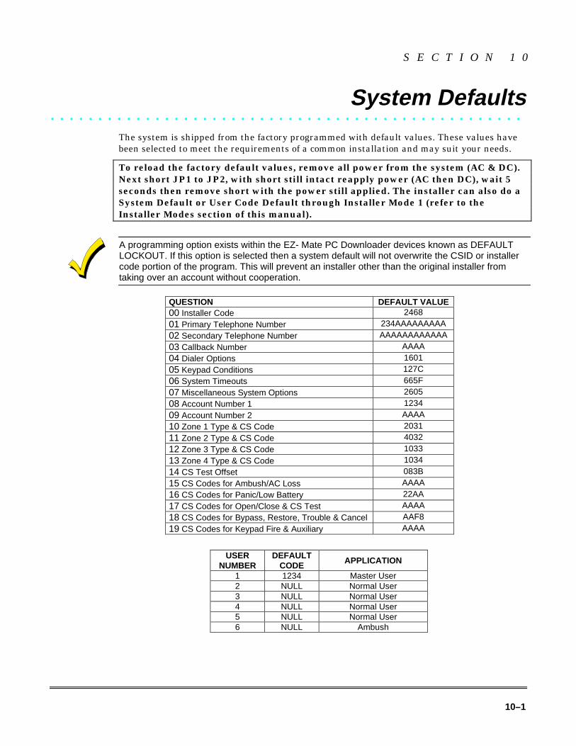
10–1
S E C T I O N 1 0
System Defaults• • • • • • • • • • • • • • • • • • • • • • • • • • • • • • • • • • • • • • • • • • • • • • • • • •
The system is shipped from the factory programmed with default values. These values havebeen selected to meet the requirements of a common installation and may suit your needs.
To reload the factory default values, remove all power from the system (AC & DC).Next short JP1 to JP2, with short still intact reapply power (AC then DC), wait 5seconds then remove short with the power still applied. The installer can also do aSystem Default or User Code Default through Installer Mode 1 (refer to theInstaller Modes section of this manual).
A programming option exists within the EZ- Mate PC Downloader devices known as DEFAULTLOCKOUT. If this option is selected then a system default will not overwrite the CSID or installercode portion of the program. This will prevent an installer other than the original installer fromtaking over an account without cooperation.
QUESTION DEFAULT VALUE00 Installer Code 2468
01 Primary Telephone Number 234AAAAAAAAA
02 Secondary Telephone Number AAAAAAAAAAAA
03 Callback Number AAAA
04 Dialer Options 1601
05 Keypad Conditions 127C
06 System Timeouts 665F
07 Miscellaneous System Options 2605
08 Account Number 1 1234
09 Account Number 2 AAAA
10 Zone 1 Type & CS Code 2031
11 Zone 2 Type & CS Code 4032
12 Zone 3 Type & CS Code 1033
13 Zone 4 Type & CS Code 1034
14 CS Test Offset 083B
15 CS Codes for Ambush/AC Loss AAAA
16 CS Codes for Panic/Low Battery 22AA
17 CS Codes for Open/Close & CS Test AAAA
18 CS Codes for Bypass, Restore, Trouble & Cancel AAF8
19 CS Codes for Keypad Fire & Auxiliary AAAA
USERNUMBER
DEFAULTCODE APPLICATION
1 1234 Master User2 NULL Normal User3 NULL Normal User4 NULL Normal User5 NULL Normal User6 NULL Ambush

XL-1S Hookup and Installation Instructions
10–2
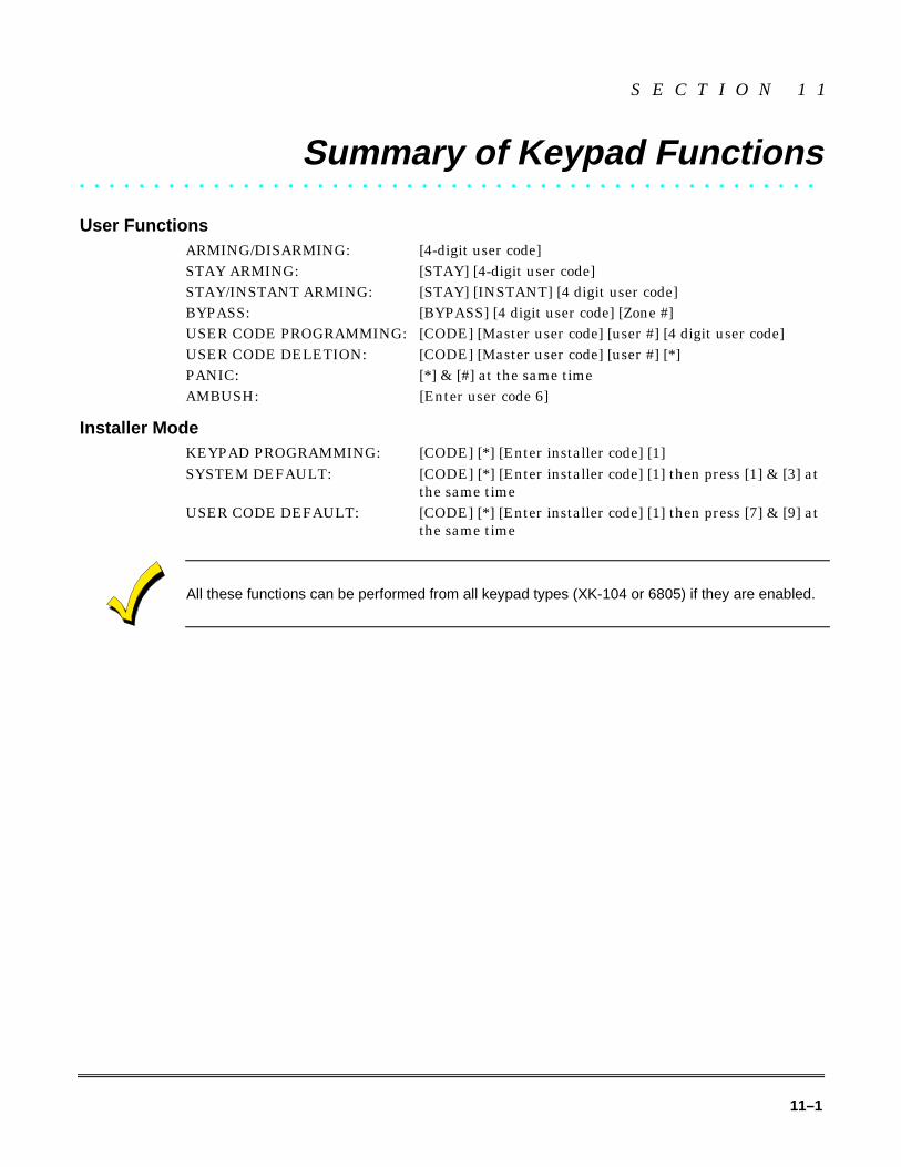
11–1
S E C T I O N 1 1
Summary of Keypad Functions• • • • • • • • • • • • • • • • • • • • • • • • • • • • • • • • • • • • • • • • • • • • • • • • • •
User FunctionsARMING/DISARMING: [4-digit user code]STAY ARMING: [STAY] [4-digit user code]STAY/INSTANT ARMING: [STAY] [INSTANT] [4 digit user code]BYPASS: [BYPASS] [4 digit user code] [Zone #]USER CODE PROGRAMMING: [CODE] [Master user code] [user #] [4 digit user code]USER CODE DELETION: [CODE] [Master user code] [user #] [*]PANIC: [*] & [#] at the same timeAMBUSH: [Enter user code 6]
Installer ModeKEYPAD PROGRAMMING: [CODE] [*] [Enter installer code] [1]SYSTEM DEFAULT: [CODE] [*] [Enter installer code] [1] then press [1] & [3] at
the same timeUSER CODE DEFAULT: [CODE] [*] [Enter installer code] [1] then press [7] & [9] at
the same time
All these functions can be performed from all keypad types (XK-104 or 6805) if they are enabled.

XL-1S Hookup and Installation Instructions
11–2

A–1
A P P E N D I X A
Central Station Reporting Formats• • • • • • • • • • • • • • • • • • • • • • • • • • • • • • • • • • • • • • • • • • • • • • • • • •
This security system is designed to transmit data to a Central Station Receiver when anAlarm, System Trouble, or an Opening/Closing occurs. Due to the many different types of CSreceivers in the market, this system can transmit data in various formats. Each installingcompany determines which format best suits its needs based on many factors. Of these, theCS receiver type is a major factor.
In transmitting data to the CS receiver, the first event that occurs is that the system's digitalcommunicator will seize the home phone lines. Then, it will dial the CS#1 telephone number(programming question #01). When the CS receiver picks up the ringing phone line, it willtransmit a "Handshake" frequency (either 1400Hz, 2300Hz or HiLo) back to the digitalcommunicator. After receiving the "Handshake" frequency, the digital communicator willtransmit the data in the format programmed in question #04, locations 1, 2 & 3 (either inPulse or DTMF). Assuming the CS receiver verifies the data transmission as valid (after 2successful rounds of data or 1 valid parity round), it will transmit a "Kissoff" frequency backto the digital communicator. This causes the communicator to stop transmitting, unless moredata is available, in which case additional data transmissions and "Kissoffs" will occur. Afterthe final "Kissoff", the CS receiver will release the phone line and process the data to itsdisplay and associated peripherals (computer and printer). If for any reason the digitalcommunicator does not receive the "Kissoff", it will proceed to dial the CS#2 telephonenumber or dial again the CS#1 telephone number (if CS#2 is not used). It will continue todial (8 times for each CS telephone number programmed) until a "Kissoff" is received. If afterdialing 8 times for each CS Telephone number programmed a "Kissoff" is not received, thesystem will display "Communication Failure" at the keypad. This message is cleared afterthe next successful transmission or by the user at the keypad.
Standard (3X1)The Standard Reporting Format: AAA E
Where:AAA = Three digit Account Number (PROG. QUESTS. #08 & 09)E = Single digit Event code; it is the first of the 2 programmable reporting code digits
Standard format is transmitted in Pulse and involves a 3-digit account number followed by asingle digit event code. It can be transmitted with parity (1 round of data) or without parity(2 rounds of data). A disadvantage of this format is that it can only transmit a total of 15event codes (0 - 9, B - F) without identifying zones or users. Examples:
3X1 W/O PARITY 3X1 W/PARITY123 3 (1st round) 123 3 6 (single round)123 3 (2nd round) 123 3 (resulting data)123 3 (resulting data)
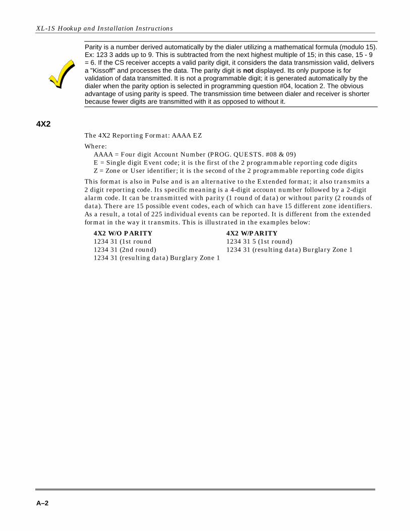
XL-1S Hookup and Installation Instructions
A–2
Parity is a number derived automatically by the dialer utilizing a mathematical formula (modulo 15).Ex: 123 3 adds up to 9. This is subtracted from the next highest multiple of 15; in this case, 15 - 9= 6. If the CS receiver accepts a valid parity digit, it considers the data transmission valid, deliversa "Kissoff" and processes the data. The parity digit is not displayed. Its only purpose is forvalidation of data transmitted. It is not a programmable digit; it is generated automatically by thedialer when the parity option is selected in programming question #04, location 2. The obviousadvantage of using parity is speed. The transmission time between dialer and receiver is shorterbecause fewer digits are transmitted with it as opposed to without it.
4X2The 4X2 Reporting Format: AAAA EZ
Where:AAAA = Four digit Account Number (PROG. QUESTS. #08 & 09)E = Single digit Event code; it is the first of the 2 programmable reporting code digitsZ = Zone or User identifier; it is the second of the 2 programmable reporting code digits
This format is also in Pulse and is an alternative to the Extended format; it also transmits a2 digit reporting code. Its specific meaning is a 4-digit account number followed by a 2-digitalarm code. It can be transmitted with parity (1 round of data) or without parity (2 rounds ofdata). There are 15 possible event codes, each of which can have 15 different zone identifiers.As a result, a total of 225 individual events can be reported. It is different from the extendedformat in the way it transmits. This is illustrated in the examples below:
4X2 W/O PARITY 4X2 W/PARITY1234 31 (1st round 1234 31 5 (1st round)1234 31 (2nd round) 1234 31 (resulting data) Burglary Zone 11234 31 (resulting data) Burglary Zone 1
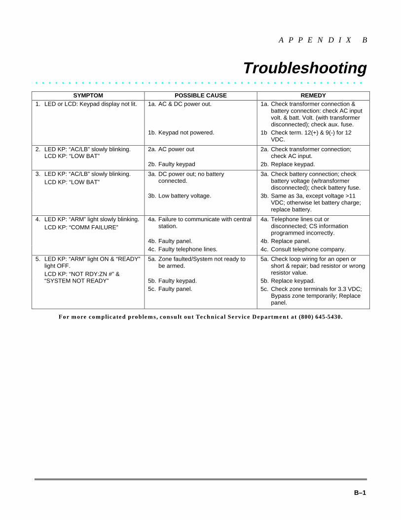
B–1
A P P E N D I X B
Troubleshooting• • • • • • • • • • • • • • • • • • • • • • • • • • • • • • • • • • • • • • • • • • • • • • • • • •
SYMPTOM POSSIBLE CAUSE REMEDY1a. AC & DC power out. 1a. Check transformer connection &
battery connection: check AC inputvolt. & batt. Volt. (with transformerdisconnected); check aux. fuse.
1. LED or LCD: Keypad display not lit.
1b. Keypad not powered. 1b Check term. 12(+) & 9(-) for 12VDC.
2a. AC power out 2a. Check transformer connection;check AC input.
2. LED KP: “AC/LB” slowly blinking.LCD KP: “LOW BAT”
2b. Faulty keypad 2b. Replace keypad.
3a. DC power out; no batteryconnected.
3a. Check battery connection; checkbattery voltage (w/transformerdisconnected); check battery fuse.
3. LED KP: “AC/LB” slowly blinking.LCD KP: “LOW BAT”
3b. Low battery voltage. 3b. Same as 3a, except voltage >11VDC; otherwise let battery charge;replace battery.
4a. Failure to communicate with centralstation.
4a. Telephone lines cut ordisconnected; CS informationprogrammed incorrectly.
4b. Faulty panel. 4b. Replace panel.
4. LED KP: “ARM” light slowly blinking.LCD KP: “COMM FAILURE”
4c. Faulty telephone lines. 4c. Consult telephone company.
5a. Zone faulted/System not ready tobe armed.
5a. Check loop wiring for an open orshort & repair; bad resistor or wrongresistor value.
5b. Faulty keypad. 5b. Replace keypad.
5. LED KP: “ARM” light ON & “READY”light OFF.LCD KP: “NOT RDY:ZN #” &“SYSTEM NOT READY”
5c. Faulty panel. 5c. Check zone terminals for 3.3 VDC;Bypass zone temporarily; Replacepanel.
For more complicated problems, consult out Technical Service Department at (800) 645-5430.

XL-1S Hookup and Installation Instructions
B–2

C–1
A P P E N D I X C
XL-1S System Planning Worksheet• • • • • • • • • • • • • • • • • • • • • • • • • • • • • • • • • • • • • • • • • • • • • • • • • •
NAME: _________________________________________ ADDRESS: _______________________________________
ZONENUMBER
AREAPROTECTED ZONE TYPE✴✴
DESCRIPTOR (12CHARACTERS)
SENSORS
1
2
3
4
5 Panic �Keyswitch �
Not Applicable
✴✴ Valid Zone Types are: Controlled Zones 24 Hour ZonesInstant/Perimeter 24 Hour AlarmDelay 24 Hour TroubleInterior Fire
USERNUMBER
APPLICATION USER NAME
1 Master User✴
2 Normal User
3 Normal User
4 Normal User
5 Normal User
6 Ambush Y � N �
✴ Only the master user (1) can add, change or delete other user codes.
KEYPADNUMBER
KEYPAD TYPE LOCATION
1 XK104 � 6805 �
2 XK104 � 6805 �
3 XK104 � 6805 �
4 XK104 � 6805 �
5 XK104 � 6805 �
6 XK104 � 6805 �

XL-1S Hookup and Installation Instructions
C–2

D–1
A P P E N D I X D
XL-1S System Programming Worksheet• • • • • • • • • • • • • • • • • • • • • • • • • • • • • • • • • • • • • • • • • • • • • • • • • •
NAME: _________________________________________ ADDRESS: _______________________________________
01 PRIMARY TELEPHONE NUMBER DEFAULT = 234AAAAAAAAAL1 L2 L3 L4 L5 L6 L7 L8 L9 L10 L11 L12
02 SECONDARY TELEPHONE NUMBER DEFAULT = AAAAAAAAAAAAL1 L2 L3 L4 L5 L6 L7 L8 L9 L10 L11 L12
03 CALLBACK TELEPHONE NUMBER DEFAULT = AAAAAAAAAAAAL1 L2 L3 L4 L5 L6 L7 L8 L9 L10 L11 L12
04 DIALER OPTIONS DEFAULT = 1601L1 L2 L3 L4
05 KEYPAD CONDITIONS DEFAULT = 127CL1 L2 L3 L4
06 SYSTEM TIMEOUTS DEFAULT = 665FL1 L2 L3 L4
07 MISC. SYS. OPTIONS DEFAULT = 2605L1 L2 L3 L4
08 ACCOUNT # 1 DEFAULT = 1234L1 L2 L3 L4
09 ACCOUNT # 2 DEFAULT = AAAAL1 L2 L3 L4
10 ZONE 1 TYPE AND CS CODE DEFAULT = 2031L1 L2 L3 L4
11 ZONE 2 TYPE AND CS CODE DEFAULT = 4132L1 L2 L3 L4
12 ZONE 3 TYPE AND CS CODE DEFAULT = 1033L1 L2 L3 L4
13 ZONE 4 TYPE AND CS CODE DEFAULT = 1034L1 L2 L3 L4
14 CS TEST OFFSET DEFAULT = 083BL1 L2 L3 L4
15 AMBUSH AND AC LOSS DEFAULT = AAAAL1 L2 L3 L4
16 PANIC AND LOW BATTERY DEFAULT = 22AAL1 L2 L3 L4
17 OPEN, CLOSE & CS TEST DEFAULT = AAAAL1 L2 L3 L4
18 BYP, REST, TRBL, & CANC. DEFAULT = AAF8L1 L2 L3 L4
19 KEYPAD FIRE & KEYPAD AUX. DEFAULT = AAAAL1 L2 L3 L4
00 INSTALLER CODE DEFAULT = 2468L1 L2 L3 L4
TO ENTER PROGRAMMING[CODE] [*] [4 digit Installer Code] [1]
TO SKIP TO A QUESTION[*] {2 digit Question Number]
TO MOVE WITHIN A QUESTIONPress the [#] until the desired location is reached.
TO ENTER DATA[single digit: 0 - 9, A - F] [#]
HEXADECIMAL ENTRIESA = [CODE] [1] D = [CODE] [4]B = [CODE] [2] E = [CODE] [5]C = [CODE] [3] F = [CODE] [6]
TO EXIT PROGRAMMING:Press the [STAY].
PROGRAMMED BY: ________________________________ DATE: ______________________________

XL-1S Hookup and Installation Instructions
D–2

E–1
A P P E N D I X E
Warnings and Limitations• • • • • • • • • • • • • • • • • • • • • • • • • • • • • • • • • • • • • • • • • • • • • • • • • •
Warning Limitations of This Alarm SystemWhile this system is an advanced design security system, it does not offer guaranteed protection against burglary, fire or otheremergency. Any alarm system, whether commercial or residential, is subject to compromise or failure to warn for a variety ofreasons. For example:
• Intruders may gain access through unprotected openings or have the technical sophistication to bypass an alarm sensoror disconnect an alarm warning device.
• Intrusion detectors (e.g., passive infrared detectors), smoke detectors, and many other sensing devices will not workwithout power. Battery operated devices will not work without batteries, with dead batteries or if the batteries are not putin properly. Devices powered solely by AC will not work if their AC power supply is cut off for any reason, however briefly.
• Signals sent by wireless transmitters may be blocked or reflected by metal before they reach the alarm receiver. Even ifthe signal path has been recently checked during a weekly test, blockage can occur if a metal object is moved into thepath.
• A user may not be able to reach a panic or emergency button quickly enough.
• While smoke detectors have played a key role in reducing residential fire deaths in the United States, they may notactivate or provide early warning for a variety of reasons. In as many as 35% of all fires, according to data published bythe Federal Emergency Management Agency. Some of the reasons smoke detectors used in conjunction with thisSystem may not work are as follows: Smoke detectors may have been improperly installed and positioned. Smokedetectors may not sense fires that start where smoke cannot reach the detectors, such as in chimneys, in walls, or roofs,or on the other side of closed doors. Smoke detectors may not sense a fire on another level of a residence or building. Asecond floor detector, for example, may not sense a first floor or basement fire. Moreover, smoke detectors have sensinglimitations. No smoke detector can sense every kind of fire every time. In general, detectors may not always warn aboutfires caused by carelessness and safety hazards like smoking in bed, violent explosions, escaping gas, improper storageof flammable materials, overloaded electrical circuits, children playing with matches, or arson. Depending on the natureof the fire and/or the location of the smoke detectors, the detector, even if it operates as anticipated, may not providesufficient warning to allow all occupants to escape in time to prevent injury or death.
• Passive Infrared Motion Detectors can only detect intrusion within the designed ranges as diagrammed in theirinstallation manual. Passive Infrared Detectors do not provide volumetric area protection. They do create multiple beamsof protection, and intrusion can only be detected in unobstructed areas covered by the beams. They cannot detect motionor intrusion that takes place behind walls, ceilings, floors, closed doors, glass partitions, glass doors, or window.Mechanical tampering, masking, painting, or spraying of any material on the mirrors, windows or any part of the opticalsystem can reduce their detection ability. Passive Infrared Detectors sense changes in temperature; however, as theambient temperature of the protected area approaches the temperature range of 90 to 150F, the detection performancecan decrease.
• Alarm warning devices such as sirens, bells or horns may not alert people or wake up sleepers who are located on theother side of closed or partly open doors. If warning devices sound on a different level of the residence from thebedrooms, then they are less likely to waken or alert people inside the bedrooms. Even persons who are awake may nothear the warning if the alarm is muffled by noise from a stereo, radio, air conditioner or other appliances, or by passingtraffic. Finally, alarm warning devices, however loud, may not warn hearing-impaired people or waken deep sleepers.
• Telephone lines needed to transmit alarm signals from a premises to a central monitoring station may be out of service ortemporarily out of service. Telephone lines are also subject to compromise by sophisticated intruders.
• Even if the system responds to the emergency as intended, however, occupants may have insufficient time to protectthemselves from the emergency situation. In the case of a monitored alarm system, authorities may not respondappropriately.
• This equipment, like other electrical devices, is subject to component failure. Even though this equipment is designed tolast as long as 10 years, the electronic components could fail at any time.
The most common cause of an alarm system not functioning when an intrusion or fire occurs is inadequate maintenance. Thisalarm system should be tested weekly to make sure all sensors are working properly. Installing an alarm system may make

XL-1S Hookup and Installation Instructions
E–2
one eligible for lower insurance rates, but an alarm system is not a substitute for insurance. Homeowners, property ownersand renters should continue to act prudently in protecting themselves and continue to insure their lives and property.
We continue to develop new and improved protection devices. Users of alarm systems owe it to themselves and their lovedones to learn about these developments.

F–1
A P P E N D I X F
FCC Statement and Telephone Problems• • • • • • • • • • • • • • • • • • • • • • • • • • • • • • • • • • • • • • • • • • • • • • • • • •
Federal Communications Commission (FCC) StatementThis equipment has been tested to FCC requirements and has been found acceptable for use. The FCC requires the followingstatement for your information.
This equipment generates and uses radio frequency energy and if not installed and used properly, that is in strict accordancewith the manufacturer's instructions may cause interference to radio and television reception. It has been tested and found tocomply with the limits of Part 15 of FCC Rules, which are designed to provide reasonable protection against such interferencein a residential installation. However, there is no guarantee that interference will not occur in a particular installation. If thisequipment does not cause interference to radio or television reception, which can be determined by turning the equipment offand on, the user is encouraged to try to correct the interference by one or more of the following measures:
• If using an indoor antenna, have a quality outdoor antenna installed.
• Reorient the receiving antenna until interference is reduced or eliminated.
• Move the radio or television receiver away from the control/ communicator.
• Move the antenna leads away from any wire runs to the control/communicator.
• Plug the control/communicator into a different outlet so that it and the radio or television receiver are on different branchcircuits.
If necessary, the user should consult the dealer or an experienced radio/television technician for additional suggestions.
The user may find the following booklet prepared by the Federal Communications Commission helpful:
Interference Handbook"
This booklet is available from the U.S. Government Printing Office, Washington, DC 20402. Stock No. 004-000-00450-7.
The user shall not make any changes or modifications to the equipment unless authorized by the installation Instructions orUser's Manual. Unauthorized changes or modifications could void the user's authority to operate the equipment.
In the Event of Telephone Operational ProblemsIn the event of telephone operational problems, disconnect the communicator by removing the plug from the RJ31X jack. Donot disconnect the phone connection inside the communicator. Doing so will result in the loss of your phone lines. If the regularphone works correctly after the communicator has been disconnected from the phone lines, the communicator has a problemand should be returned for repair. If upon disconnection of the communicator, there is still a problem on your line, notify thetelephone company that they have a problem and request prompt repair service. The user may not under any circumstances(in or out of warranty) attempt any service or repairs on the system. It must be returned to the factory or an authorized serviceagency for all repairs.

XL-1S Hookup and Installation Instructions
F–2

G–1
A P P E N D I X G
Warranty• • • • • • • • • • • • • • • • • • • • • • • • • • • • • • • • • • • • • • • • • • • • • • • • • •
FBII Limited WarrantyFire Burglary Instruments, Inc., a Subsidiary of Pittway Corporation, and Pittway Corporation its divisions, subsidiaries andaffiliates ("Seller"), 149 Eileen Way, Syosset, New York 11791 warrants its products to be in conformance with its own plansand specifications and to be free from defects in materials and workmanship under normal use and service for 5 years fromthe date stamp control on the product, or for products not having a date stamp, for 5 years from the date of original purchaseunless the installation instructions or catalog sets forth a shorter period, in which case the shorter period shall apply. Seller'sobligation shall be limited to repairing or replacing, at its option, free of charge for materials or labor, any product which isproved not in compliance with Seller's specifications or proves defective in materials or workmanship under normal use andservice. Seller shall have no obligation under this Limited Warranty or otherwise if the product is altered or improperly repairedor serviced by anyone other than Seller. For warranty service, return transportation prepaid, to Factory Service, 149 EileenWay, Syosset, New York 11791.
THERE ARE NO WARRANTIES, EXPRESSED OR IMPLIED, OF MERCHANTABILITY, OR FITNESS FOR A PARTICULARPURPOSE OR OTHERWISE, WHICH EXTEND BEYOND THE DESCRIPTION ON THE FACE HEREOF. IN NO CASESHALL SELLER BE LIABLE TO ANYONE FOR ANY CONSEQUENTIAL OR INCIDENTAL DAMAGES FOR BREACH OFTHIS OR ANY OTHER WARRANTY, EXPRESS OR IMPLIED, OR UPON ANY OTHER BASIS OF LIABILITYWHATSOEVER, EVEN THE LOSS OR DAMAGE IS CAUSED BY THE SELLER'S OWN NEGLIGENCE OR FAULT.
Seller does not represent that the products it sells may not be compromised or circumvented; that the products will preventany personal injury or property loss by burglary, robbery, fire or otherwise; or that the products will in all cases provideadequate warning or protection. Customer understands that a properly installed and maintained alarm system may onlyreduce the risk of a burglary, robbery, fire, or other events occurring without providing an alarm, but it is not insurance or aguarantee that such will not occur or that there will be no personal injury or property loss as a result. CONSEQUENTLY,SELLER SHALL HAVE NO LIABILITY FOR ANY PERSONAL INJURY, PROPERTY DAMAGE OR OTHER LOSS BASED ONA CLAIM THE PRODUCT FAILED TO GIVE ANY WARNING. HOWEVER, IF SELLER IS HELD LIABLE, WHETHERDIRECTLY OR INDIRECTLY, FOR ANY LOSS OR DAMAGE ARISING UNDER THIS LIMITED WARRANTY OROTHERWISE, REGARDLESS OF CAUSE OR ORIGIN, SELLER'S MAXIMUM LIABILITY SHALL NOT IN ANY CASEEXCEED THE PURCHASE PRICE OF THE PRODUCT, WHICH SHALL BE THE COMPLETE AND EXCLUSIVE REMEDYAGAINST SELLER. This warranty replaces any previous warranties and is the only warranty made by seller on this product.No increase or alteration, written or verbal, on the obligations of this Limited Warranty is authorized.

¬1����9�;lN9471V1 06/98
Copyright © 1998 PITTWAY CORPORATION