Alarm Manager Plug-in User's Guide - Startelstartel.com/wp-content/uploads/user_guides/Startel Alarm...
54
Alarm Manager Plug-in User’s Guide
Transcript of Alarm Manager Plug-in User's Guide - Startelstartel.com/wp-content/uploads/user_guides/Startel Alarm...
Alarm Manager Plug-in
User’s Guide

While every attempt is made to ensure both accuracy and completeness of information included in this document, errors can occur, and updates or improvements may be implemented without notice. For these reasons, Startel cannot accept responsibility for the complete accuracy of this data.
Microsoft, Windows, Windows 7, Windows XP Professional, Windows 2008 Server, SQL Server 2008, Microsoft Internet Information Ser-vices (IIS) are copyrights, trademarks, or registered trademarks of Microsoft Corporation.
All other brand and product names are trademarks or registered trademarks of their respective holders.
Part Number: 91-1184-001
This manual reflects Administrative Controls version 12.0.
© Copyright 2013 by Startel Corporation
The information contained herein is proprietary to, and considered a trade secret of, Startel Corporation, and shall not be reproduced, transmitted, transcribed, or stored in any retrieval system in any form or by any means, electronic, mechanical, magnetic, optical, chemi-cal, manual, or otherwise, without the express written permission of Startel Corporation, 16 Goodyear, Bldg. B # 125, Irvine, California 92618, U.S.A.
Revision Date: October 28, 2013
Contents
Alarm Manager Plug-in.....................................................................................5
Introduction to the Alarm Manager .....................................................................6
Alarm Manager Requirements ........................................................................6
Before You Begin ............................................................................................6
Launching the Alarm Manager Plug-in............................................................8
Alarm Manager Element Summary .................................................................9
Using the Alarm Manager: A Simple Road Map ...........................................10
Alarm Manager Elements Reference ................................................................11
The Configuration Element ...........................................................................12
The Notifications Element .............................................................................14
The Alarms Element......................................................................................17
Adding Alarms in the Alarms Element ...................................................... 17
Alarm Types ............................................................................................. 20
Grouping & Sorting Alarms in the Alarms Element .................................. 30
Editing, Removing, and Copying Alarms .................................................. 32
The Peers Element .......................................................................................35
The VOIP Trunks Element ............................................................................38
The DAHDI Groups Element.........................................................................41
The Queues Element ....................................................................................44
3

The Switches Element.................................................................................. 47
The Active Alarms Element .......................................................................... 50
Index ................................................................................................................ 52
4
Alarm Manager Plug-in
This document describes how to use the Alarm Manager Plug-in within Startel CMC Administrative Controls. Sections include:
Introduction to the Alarm Manager (page 6)
• Alarm Manager Requirements (page 6)
• Before You Begin (page 6)
• Launching the Alarm Manager Plug-in (page 8)
• Alarm Manager Elements Summary (page 9)
• Using the Alarm Manager: A Simple Road Map (page 10)
Alarm Manager Elements Reference (page 11)
• The Configuration Element (page 12)
• The Notifications Element (page 14)
• The Alarms Element (page 17)
• The Peers Element (page 35)
• The DAHDI Groups Element (page 41)
• The Queues Element (page 44)
• The Switches Element (page 47)
• The Active Alarms Element (page 50)
5
Alarm Manager Plug-in User’s Guide
INTRODUCTION TO THE ALARM MANAGER
You can create alarms that activate if your call volume requires more agents, if new calls aren't being answered quickly enough, if Hold times are too long, if phones lose their registration with your Switch—to name just a few examples.
Before you begin using the Alarm Manager plug-in, please spend a few minutes reading the following introductory topics.
Alarm Manager Requirements (page 6)
Before You Begin (page 6)
Launching the Alarm Manager Plug-in (page 8)
Alarm Manager Elements Summary (page 9)
Using the Alarm Manager: A Simple Road Map (page 10)
Alarm Manager Requirements
To use the Alarm Manager plug-in in your Startel system, your site must have the following installed and running:
Startel Soft Switch (minimum 1.0.5, build 1025) & API Server (minimum 0.5.5)
CMC version 12.0 or higher (includes Alarm Manager plug-in)
The Startel Soft Switch Monitor service (included in CMC version 12.0)
Before You Begin
Before you begin configuring alarms, please read and absorb each of the informa-tion points provided below. Taken together, they provide an overview that will help you to understand how to use the various elements of the Alarm Manager plug-in.
The Alarm Manager plug-in consists of multiple elements, each selectable in the left pane of the Alarm Manager window. (For a summary description of each element, see page 9.)
Many of the elements are for assigning alarms to specific system components—for example, to phones (peers), or trunks, or Call Queues. These elements are: Peers; VOIP Trunks; DAHDI Groups; Queues; Switches.
Some elements have other uses. The Configuration element is for specifying the location of the Startel Soft Switch Monitor Service (and for setting a couple of Display preferences). The Notifications element is for configuring Alarm
In a Startel CMC System with a Soft Switch, you can use the Alarm Manager plug-in to define and manage alarms that will alert you when conditions in your system are not meeting specified service criteria.
6

Alarm Manager Plug-in User’s Guide
Notifications. The Switches element is for telling the Switch Monitor Service how to communicate with your Soft Switch. (You can also use it to assign an alarm to your Switch—or Switches.) The Active Alarms element is for viewing and clearing active alarms.
The Alarms element, which is displayed by default when you launch the plug-in, provides a single location where you can add (define) all types of alarms, and view all the alarms that have been defined for your system. Though it’s possible to define alarms in other elements (the ones used to assign alarms), it’s generally recommended that you use the Alarms element, which is easy to use, and where you can set parameters that may not be available in other elements.
Note: There is a distinction between adding an alarm, and assigning an alarm. Adding basically means defining. Once an alarm is added (defined), it becomes available for assignment to compatible system components via menu selection.
You cannot assign alarms in the Alarms element. (Nor does the Alarms element show you Alarm assignments. These can only be viewed in the elements that were used to make the assignments.) To assign an alarm to a system component you must use one of these elements: Peers; VOIP Trunks; DAHDI Groups; Queues; Switches.
The table that follows lists all of the available alarm types, and shows you the element with which each type is associated. Each of these alarm types is described in detail under the "Alarm Types" heading on page 20.
Element Available Alarm Types
Peer • Peer Registration
• Peer Reachability
• Peer Lag
• Peer Call Limit
• Peer Max Call
VOIP Trunk • Trunk Registration
DAHDI Group • DAHDI Call Limit
• DAHDI Max Call
• DAHDI State
Queue • Call to Agent Ratio
• Join Empty
• Leave Empty
• Automatic Sign Off
• New Call Starvation
• Hold Call Starvation
Switch • Switch Connection
7
Alarm Manager Plug-in User’s Guide
Launching the Alarm Manager Plug-in
Follow these steps to launch the Alarm Manager plug-in from the Adminis-trative Controls (AC) Home page:
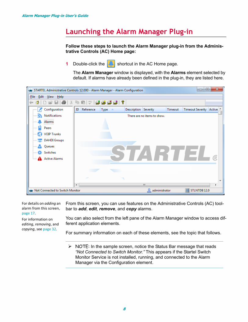
1 Double-click the shortcut in the AC Home page.
The Alarm Manager window is displayed, with the Alarms element selected by default. If alarms have already been defined in the plug-in, they are listed here.
From this screen, you can use features on the Administrative Controls (AC) tool-bar to add, edit, remove, and copy alarms.
You can also select from the left pane of the Alarm Manager window to access dif-ferent application elements.
For summary information on each of these elements, see the topic that follows.
NOTE: In the sample screen, notice the Status Bar message that reads “Not Connected to Switch Monitor.” This appears if the Startel Switch Monitor Service is not installed, running, and connected to the Alarm Manager via the Configuration element.
For details on adding an alarm from this screen, page 17.For information on editing, removing, and copying, see page 32.
8

Alarm Manager Plug-in User’s Guide
Alarm Manager Elements Summary
Element Description Complete Info:
Configuration This element is used to specify the location of the Soft Switch Monitor service (required), and select session Display preferences (optional).
page 12
Notifications This element allows you to configure Alarm Notifica-tions that will be sent in the event that alarms are trig-gered in your system.
Note: Alarm Notifications require that the transport (or transports) for delivering the notifications be set up in the Client Maintenance plug-in.
page 14
Alarms This element allows you to add, edit, remove, copy, and view alarms of all available types.
Alarms you add (define) here are not implemented—they are simply made available for selection in the other elements that you will use to assign alarms to specific system components.
Note: You’re able to add alarms “on the fly” in other elements, but Startel recommends that you add alarms in the Alarms element.
page 17
Peers This element is used to assign alarms to specific peers in your system. A peer is commonly a phone, but it can also be another switch.
page 35
VOIP Trunks This element is used to assign alarms to specific VOIP trunks in your system.
page 38
DAHDI Groups This element is used to assign alarms to groups of DAHDI channels in your system. (A DAHDI channel is a non-VOIP telephony channel.)
page 41
Queues This element is used to assign alarms to specific Call Queues in your system.
page 44
Switches This element must be configured to enable communi-cation between the Switch Monitor Service and your Soft Switch. You can also use this element to assign an alarm to your Soft Switch (or Switches, if you have more than one).
page 47
Active Alarms This element displays a screen where you can view and clear alarms that have triggered in your system.
page 50
9
Alarm Manager Plug-in User’s Guide
Using the Alarm Manager: A Simple Road Map
If you’ve read and understood the topics in this Introductory section, you should understand how the Alarm Manager works, and be able to begin creating alarms.
The Reference Section topics that comprise the second part of this manual pro-vide step-by-step instructions and details that will help you with each element that you need to use. (You may not need to use them all.)
As a simple road map for getting started, here are the basic steps that you’re advised to follow to set up alarms for your Startel system.
1 Make sure the Startel Soft Switch Monitor Service is running, and that your Soft Switch is configured.
2 Plan your alarms. (Which alarms do you want to implement, and how do you want to be notified?)
3 Create your Alarm Notifications.
4 Define (Add) the alarms you want to use.
5 Assign the alarms to specific components.
6 Test the alarms.
10
Alarm Manager Plug-in User’s Guide
ALARM MANAGER ELEMENTS REFERENCEThis section provides detailed information on how to use each of the Alarm Man-ager elements—ordered as they appear in the Alarm Manager User Interface.
Topics in this section include:
The Configuration Element (page 12)
The Notifications Element (page 14)
The Alarms Element (page 17)
The Peers Element (page 35)
The DAHDI Groups Element (page 41)
The Queues Element (page 44)
The Switches Element (page 47)
The Active Alarms Element (page 50)
For information on the order in which these elements are best used to create system alarms, see "Using the Alarm Manager: A Simple Road Map" on page 10.
11
Alarm Manager Plug-in User’s Guide
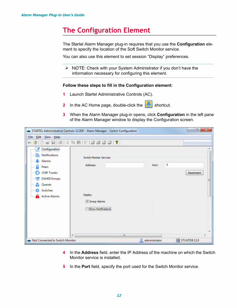
The Configuration Element
The Startel Alarm Manager plug-in requires that you use the Configuration ele-ment to specify the location of the Soft Switch Monitor service.
You can also use this element to set session “Display” preferences.
Follow these steps to fill in the Configuration element:
1 Launch Startel Administrative Controls (AC).
2 In the AC Home page, double-click the shortcut.
3 When the Alarm Manager plug-in opens, click Configuration in the left pane of the Alarm Manager window to display the Configuration screen.
4 In the Address field, enter the IP Address of the machine on which the Switch Monitor service is installed.
5 In the Port field, specify the port used for the Switch Monitor service.
NOTE: Check with your System Administrator if you don’t have the information necessary for configuring this element.
12
Alarm Manager Plug-in User’s Guide
6 Under the Display heading:
• Select or clear the Group Alarms checkbox to indicate if you want the Alarms element screen to group alarms by type. By default, this option is selected. (See page 30 for more on grouping/ungrouping.)
• Select Show Notifications if you want Alarm Notification assignments to be represented in the opening “list screens” of the elements used to assign alarms. By default, this option is not selected.
7 When you’re finished, click (Save) on the AC toolbar to save.
Using the Reconnect Button
Notice the Reconnect button in the Configuration screen. This feature allows you to reconnect the Alarm Manager plug-in to the Switch Monitor service, if necessary. If you see a Status Bar message that reads “Not Connected to Switch Monitor” (see the note on page 8), you can attempt to reconnect using the Reconnect button.
And note: If you have moved the service, you’ll need to update the Configura-tion IP Address and Port settings as well.
Note: Changes you make to checkbox options apply to the current session only.
13

Alarm Manager Plug-in User’s Guide
The Notifications Element
The Notifications element of the Alarm Manager plug-in is for defining the “Notifi-cation” messages that will go out when alarms are triggered in your system.
The Alarm Manager sends Notification messages using client transports defined in the Client Info element of the Client Maintenance plug-in (e.g., E-mail, Fax, Alpha Pager, etc.). You will therefore need to either set up a special client for these transports, or define transports for the System client, and use those trans-ports for Notification messages. In any case, you will need to define these trans-ports prior to configuring Alarm Manager “Notification” parameters.
And note: You do NOT have to configure the text messages that will be sent by the transports. These are hard-coded in the system. For example, here is an alarm message that was sent out via e-mail:
On Configuring Phone Notifications (for Advanced Users)
If you want Alarm Notifications sent by phone, your need to configure two Scenarios in the Soft Switch Web Config application: one for dialing out, (AlarmOut), and one for playing the recording (AlarmFrom).
The AlarmOut Scenario will allow the phone notification to dial out of the system. (Very simply, this Scenario could point to OutDials.) Once the phone call is answered, the system will look for the AlarmFrom Scenario using the Client ID of the phone transport used in the Notification. The Alar-From Scenario will “playback” the Notification recording to the caller.
Two variables will be passed between the two Scenarios: one to indicate the type of the alarm that is notifying (stlAlarm), and one to indicate the severity of the alarm (stlSeverity). These, along with the Client ID, will allow for a complex AlarmFrom scenario that will play the appropriate recording to indicate the exact alarm that was triggered.
Alarm Type IDs for the stlAlarm variable are:
• Queue New Call Starvation Alarm: 1
• Queue Hold Call Starvation Alarm: 2
• Queue Call to Agent Ratio Alarm: 3
• Queue Automatic Sign Off Alarm: 4
• Queue Join Empty Alarm: 5
• Queue Leave Empty Alarm: 6
• Peer Registration Alarm: 7
• Peer Reachability Alarm: 8
Alarm Severity values for StlSeverity are:
• Normal: 0
• Minor: 1
• Peer Lag Alarm: 9
• Peer Max Call Alarm: 10
• Peer Call Limit Alarm: 11
• VOIP Trunks Registration Alarm: 12
• DAHDI Group State Alarm: 13
• DAHDI Group Max Call Alarm: 14
• DAHDI Group Call Limit Alarm: 15
• Switch Connection Alarm: 16
• Major: 2
• Critical: 3
14
Alarm Manager Plug-in User’s Guide
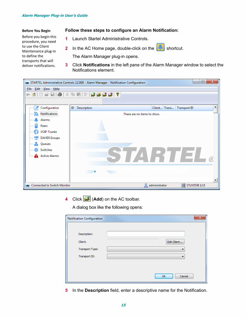
Follow these steps to configure an Alarm Notification:
1 Launch Startel Administrative Controls.
2 In the AC Home page, double-click on the shortcut.
The Alarm Manager plug-in opens.
3 Click Notifications in the left pane of the Alarm Manager window to select the Notifications element.
.
4 Click (Add) on the AC toolbar.
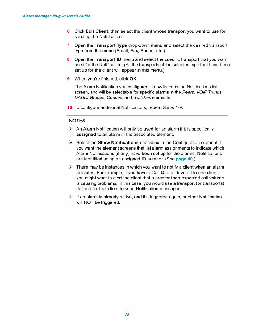
A dialog box like the following opens:
5 In the Description field, enter a descriptive name for the Notification.
Before You Begin Before you begin this procedure, you need to use the Client Maintenance plug-in to define the transports that will deliver notifications.
•
15
Alarm Manager Plug-in User’s Guide
6 Click Edit Client, then select the client whose transport you want to use for sending the Notification.
7 Open the Transport Type drop-down menu and select the desired transport type from the menu (Email, Fax, Phone, etc.).
8 Open the Transport ID menu and select the specific transport that you want used for the Notification. (All the transports of the selected type that have been set up for the client will appear in this menu.)
9 When you’re finished, click OK.
The Alarm Notification you configured is now listed in the Notifications list screen, and will be selectable for specific alarms in the Peers, VOIP Trunks, DAHDI Groups, Queues, and Switches elements.
10 To configure additional Notifications, repeat Steps 4-9.
NOTES:
An Alarm Notification will only be used for an alarm if it is specifically assigned to an alarm in the associated element.
Select the Show Notifications checkbox in the Configuration element if you want the element screens that list alarm assignments to indicate which Alarm Notifications (if any) have been set up for the alarms. Notifications are identified using an assigned ID number. (See page 40.)
There may be instances in which you want to notify a client when an alarm activates. For example, if you have a Call Queue devoted to one client, you might want to alert the client that a greater-than-expected call volume is causing problems. In this case, you would use a transport (or transports) defined for that client to send Notification messages.
If an alarm is already active, and it’s triggered again, another Notification will NOT be triggered.
16
Alarm Manager Plug-in User’s Guide
The Alarms Element
Refer to the following topics for details on how to use the Alarms element of the Alarm Manager plug-in.
Adding Alarms in the Alarms Element (page 17)
Alarm Types (page 20)
Grouping & Sorting Alarms in the Alarms Element (page 30)
Editing, Removing, and Copying Alarms (page 32)
Adding Alarms in the Alarms Element
Though it’s possible to add alarms “on the fly” in other Alarm Manager elements, it is generally recommended that you add (define) alarms in the Alarms element. The Alarms element is easy to use, and may offer a larger set of parameters.
Follow these steps to add alarm from the Alarms element:
1 Launch Startel Administrative Controls.
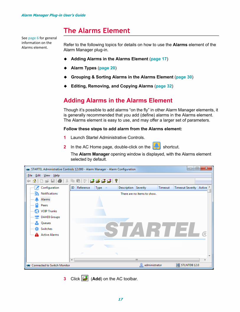
2 In the AC Home page, double-click on the shortcut.
The Alarm Manager opening window is displayed, with the Alarms element selected by default.
3 Click (Add) on the AC toolbar.
See page 6 for general information on the Alarms element.
17
Alarm Manager Plug-in User’s Guide
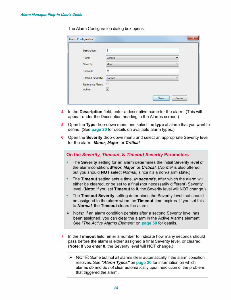
The Alarm Configuration dialog box opens.
4 In the Description field, enter a descriptive name for the alarm. (This will appear under the Description heading in the Alarms screen.)
5 Open the Type drop-down menu and select the type of alarm that you want to define. (See page 20 for details on available alarm types.)
6 Open the Severity drop-down menu and select an appropriate Severity level for the alarm: Minor; Major; or Critical.
7 In the Timeout field, enter a number to indicate how many seconds should pass before the alarm is either assigned a final Severity level, or cleared. (Note: If you enter 0, the Severity level will NOT change.)
On the Severity, Timeout, & Timeout Severity Parameters
• The Severity setting for an alarm determines the initial Severity level of the alarm condition: Minor, Major, or Critical. (Normal is also offered, but you should NOT select Normal, since it’s a non-alarm state.)
• The Timeout setting sets a time, in seconds, after which the alarm will either be cleared, or be set to a final (not necessarily different) Severity level. (Note: If you set Timeout to 0, the Severity level will NOT change.)
• The Timeout Severity setting determines the Severity level that should be assigned to the alarm when the Timeout time expires. If you set this to Normal, the Timeout clears the alarm.
Note: If an alarm condition persists after a second Severity level has been assigned, you can clear the alarm in the Active Alarms element. See "The Active Alarms Element" on page 50 for details.
NOTE: Some but not all alarms clear automatically if the alarm condition resolves. See "Alarm Types" on page 20 for information on which alarms do and do not clear automatically upon resolution of the problem that triggered the alarm.
18
Alarm Manager Plug-in User’s Guide
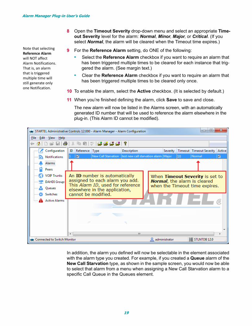
8 Open the Timeout Severity drop-down menu and select an appropriate Time-out Severity level for the alarm: Normal, Minor, Major, or Critical. (If you select Normal, the alarm will be cleared when the Timeout time expires.)
9 For the Reference Alarm setting, do ONE of the following:
• Select the Reference Alarm checkbox if you want to require an alarm that has been triggered multiple times to be cleared for each instance that trig-gered the alarm. (See margin text.)
• Clear the Reference Alarm checkbox if you want to require an alarm that has been triggered multiple times to be cleared only once.
10 To enable the alarm, select the Active checkbox. (It is selected by default.)
11 When you’re finished defining the alarm, click Save to save and close.
The new alarm will now be listed in the Alarms screen, with an automatically generated ID number that will be used to reference the alarm elsewhere in the plug-in. (This Alarm ID cannot be modified).
In addition, the alarm you defined will now be selectable in the element associated with the alarm type you created. For example, if you created a Queue alarm of the New Call Starvation type, as shown in the sample screen, you would now be able to select that alarm from a menu when assigning a New Call Starvation alarm to a specific Call Queue in the Queues element.
Note that selecting Reference Alarm will NOT affect Alarm Notifications. That is, an alarm that is triggered multiple time will still generate only one Notification.
19
Alarm Manager Plug-in User’s Guide
Alarm Types
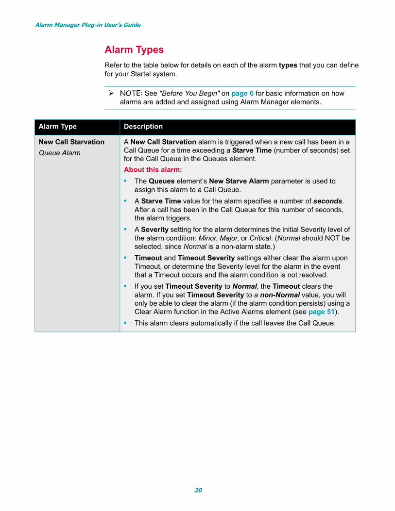
Refer to the table below for details on each of the alarm types that you can define for your Startel system.
NOTE: See "Before You Begin" on page 6 for basic information on how alarms are added and assigned using Alarm Manager elements.
Alarm Type Description
New Call Starvation
Queue Alarm
A New Call Starvation alarm is triggered when a new call has been in a Call Queue for a time exceeding a Starve Time (number of seconds) set for the Call Queue in the Queues element.
About this alarm:
• The Queues element’s New Starve Alarm parameter is used to assign this alarm to a Call Queue.
• A Starve Time value for the alarm specifies a number of seconds. After a call has been in the Call Queue for this number of seconds, the alarm triggers.
• A Severity setting for the alarm determines the initial Severity level of the alarm condition: Minor, Major, or Critical. (Normal should NOT be selected, since Normal is a non-alarm state.)
• Timeout and Timeout Severity settings either clear the alarm upon Timeout, or determine the Severity level for the alarm in the event that a Timeout occurs and the alarm condition is not resolved.
• If you set Timeout Severity to Normal, the Timeout clears the alarm. If you set Timeout Severity to a non-Normal value, you will only be able to clear the alarm (if the alarm condition persists) using a Clear Alarm function in the Active Alarms element (see page 51).
• This alarm clears automatically if the call leaves the Call Queue.
20

Alarm Manager Plug-in User’s Guide
Hold Call Starvation
Queue Alarm
A Hold Call Starvation alarm is triggered when a call has been in a Hold Queue for a time exceeding a Starve Time (number of seconds) set for the Hold Queue in the Queues element.
About this alarm:
• The Queues element’s Hold Starve Alarm parameter is used to assign this alarm to a Hold Queue.
• A Starve Time value for the alarm specifies a number of seconds. After a call has been in the Hold Queue for this number of seconds, the alarm triggers.
• A Severity setting for the alarm determines the initial Severity level of the alarm condition: Minor, Major, or Critical. (Normal should NOT be selected, since Normal is a non-alarm state.)
• Timeout and Timeout Severity settings either clear the alarm upon Timeout, or determine the Severity level for the alarm in the event that a Timeout occurs and the alarm condition is not resolved.
• If you set Timeout Severity to Normal, the Timeout clears the alarm. If you set Timeout Severity to a non-Normal value, you will only be able to clear the alarm (if the alarm condition persists) using a Clear Alarm function in the Active Alarms element (see page 51).
• This alarm clears automatically if the call leaves the Hold Queue.
Call to Agent Ratio
Queue Alarm
The Call to Agent Ratio alarm is triggered when the Call to Agent Ratio set for the alarm in the Queues element is exceeded.
Note: If the Queues element configuration supplies a Ratio value of 4 for a Call to Agent Ratio alarm (this defines a ratio of 4 calls per 1 agent) a ratio of 5 new calls per 1 agent would trigger the alarm.
About this alarm:
• The Queues element’s Call to Agent Ratio parameter is used to assign this alarm to a Call Queue.
• A Severity setting for the alarm determines the initial Severity level of the alarm condition: Minor, Major, or Critical. (Normal should NOT be selected, since Normal is a non-alarm state.)
• Timeout and Timeout Severity settings either clear the alarm, or determine the Severity level for the alarm upon Timeout.
• If you set Timeout Severity to Normal, the Timeout clears the alarm. If you set Timeout Severity to a non-Normal value, you will only be able to clear the alarm using a Clear Alarm function in the Active Alarms element (see page 51).
• No system condition automatically clears this alarm.
Alarm Type Description
21

Alarm Manager Plug-in User’s Guide
Automatic Sign Off
Queue Alarm
The Automatic Sign Off alarm is triggered when the switch automati-cally signs an agent out of a Call Queue.
About this alarm:
• The Queues element’s Automatic Signoff Alarm parameter is used to assign this alarm to a Call Queue.
• A Severity setting for the alarm determines the initial Severity level of the alarm condition: Minor, Major, or Critical. (Normal should NOT be selected, since Normal is a non-alarm state.)
• Timeout and Timeout Severity settings either clear the alarm, or determine the Severity level for the alarm upon Timeout.
• If you set Timeout Severity to Normal, the Timeout clears the alarm. If you set Timeout Severity to a non-Normal value, you will only be able to clear the alarm using a Clear Alarm function in the Active Alarms element (see page 51).
• No system condition automatically clears this alarm.
Join Empty
Queue Alarm
The Join Empty alarm is triggered when a call fails to join a Call Queue because there are no agents for the Call Queue.
About this alarm:
• The Queues element’s Join Empty Alarm parameter is used to assign this alarm to a Call Queue.
• This alarm requires that the Call Queue’s Join Empty setting be set to something other than Yes in the Soft Switch Web Config applica-tion.
• The Queues element’s Join Empty Alarm parameter is used to assign this alarm to a Call Queue.
• A Severity setting for the alarm determines the initial Severity level of the alarm condition: Minor, Major, or Critical. (Normal should NOT be selected, since Normal is a non-alarm state.)
• Timeout and Timeout Severity settings either clear the alarm, or determine the Severity level for the alarm upon Timeout.
• If you set Timeout Severity to Normal, the Timeout clears the alarm. If you set Timeout Severity to a non-Normal value, you will only be able to clear the alarm using a Clear Alarm function in the Active Alarms element (see page 51).
• No system condition automatically clears this alarm.
Alarm Type Description
22
Alarm Manager Plug-in User’s Guide
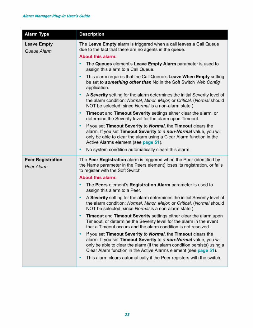
Leave Empty
Queue Alarm
The Leave Empty alarm is triggered when a call leaves a Call Queue due to the fact that there are no agents in the queue.
About this alarm:
• The Queues element’s Leave Empty Alarm parameter is used to assign this alarm to a Call Queue.
• This alarm requires that the Call Queue’s Leave When Empty setting be set to something other than No in the Soft Switch Web Config application.
• A Severity setting for the alarm determines the initial Severity level of the alarm condition: Normal, Minor, Major, or Critical. (Normal should NOT be selected, since Normal is a non-alarm state.)
• Timeout and Timeout Severity settings either clear the alarm, or determine the Severity level for the alarm upon Timeout.
• If you set Timeout Severity to Normal, the Timeout clears the alarm. If you set Timeout Severity to a non-Normal value, you will only be able to clear the alarm using a Clear Alarm function in the Active Alarms element (see page 51).
• No system condition automatically clears this alarm.
Peer Registration
Peer Alarm
The Peer Registration alarm is triggered when the Peer (identified by the Name parameter in the Peers element) loses its registration, or fails to register with the Soft Switch.
About this alarm:
• The Peers element’s Registration Alarm parameter is used to assign this alarm to a Peer.
• A Severity setting for the alarm determines the initial Severity level of the alarm condition: Normal, Minor, Major, or Critical. (Normal should NOT be selected, since Normal is a non-alarm state.)
• Timeout and Timeout Severity settings either clear the alarm upon Timeout, or determine the Severity level for the alarm in the event that a Timeout occurs and the alarm condition is not resolved.
• If you set Timeout Severity to Normal, the Timeout clears the alarm. If you set Timeout Severity to a non-Normal value, you will only be able to clear the alarm (if the alarm condition persists) using a Clear Alarm function in the Active Alarms element (see page 51).
• This alarm clears automatically if the Peer registers with the switch.
Alarm Type Description
23
Alarm Manager Plug-in User’s Guide
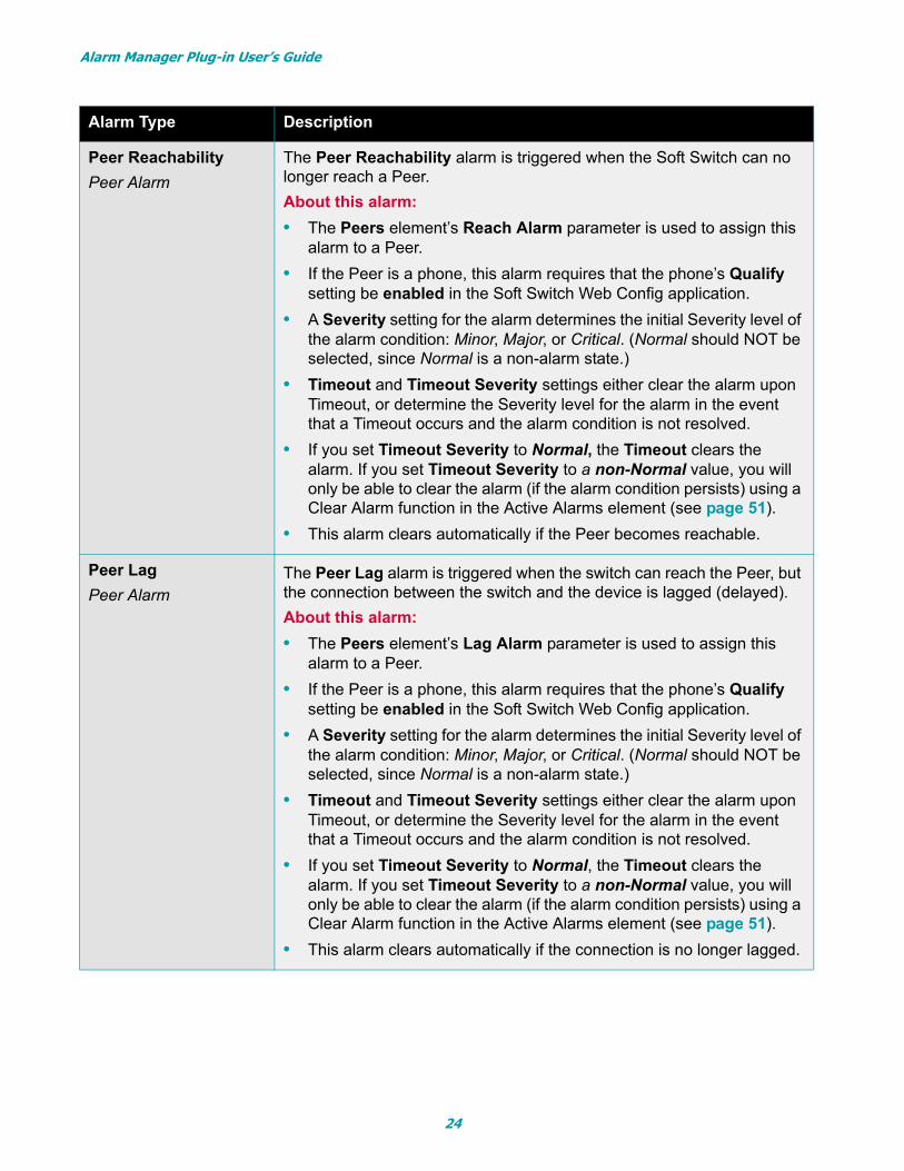
Peer Reachability
Peer Alarm
The Peer Reachability alarm is triggered when the Soft Switch can no longer reach a Peer.
About this alarm:
• The Peers element’s Reach Alarm parameter is used to assign this alarm to a Peer.
• If the Peer is a phone, this alarm requires that the phone’s Qualify setting be enabled in the Soft Switch Web Config application.
• A Severity setting for the alarm determines the initial Severity level of the alarm condition: Minor, Major, or Critical. (Normal should NOT be selected, since Normal is a non-alarm state.)
• Timeout and Timeout Severity settings either clear the alarm upon Timeout, or determine the Severity level for the alarm in the event that a Timeout occurs and the alarm condition is not resolved.
• If you set Timeout Severity to Normal, the Timeout clears the alarm. If you set Timeout Severity to a non-Normal value, you will only be able to clear the alarm (if the alarm condition persists) using a Clear Alarm function in the Active Alarms element (see page 51).
• This alarm clears automatically if the Peer becomes reachable.
Peer Lag
Peer AlarmThe Peer Lag alarm is triggered when the switch can reach the Peer, but the connection between the switch and the device is lagged (delayed).
About this alarm:
• The Peers element’s Lag Alarm parameter is used to assign this alarm to a Peer.
• If the Peer is a phone, this alarm requires that the phone’s Qualify setting be enabled in the Soft Switch Web Config application.
• A Severity setting for the alarm determines the initial Severity level of the alarm condition: Minor, Major, or Critical. (Normal should NOT be selected, since Normal is a non-alarm state.)
• Timeout and Timeout Severity settings either clear the alarm upon Timeout, or determine the Severity level for the alarm in the event that a Timeout occurs and the alarm condition is not resolved.
• If you set Timeout Severity to Normal, the Timeout clears the alarm. If you set Timeout Severity to a non-Normal value, you will only be able to clear the alarm (if the alarm condition persists) using a Clear Alarm function in the Active Alarms element (see page 51).
• This alarm clears automatically if the connection is no longer lagged.
Alarm Type Description
24
Alarm Manager Plug-in User’s Guide
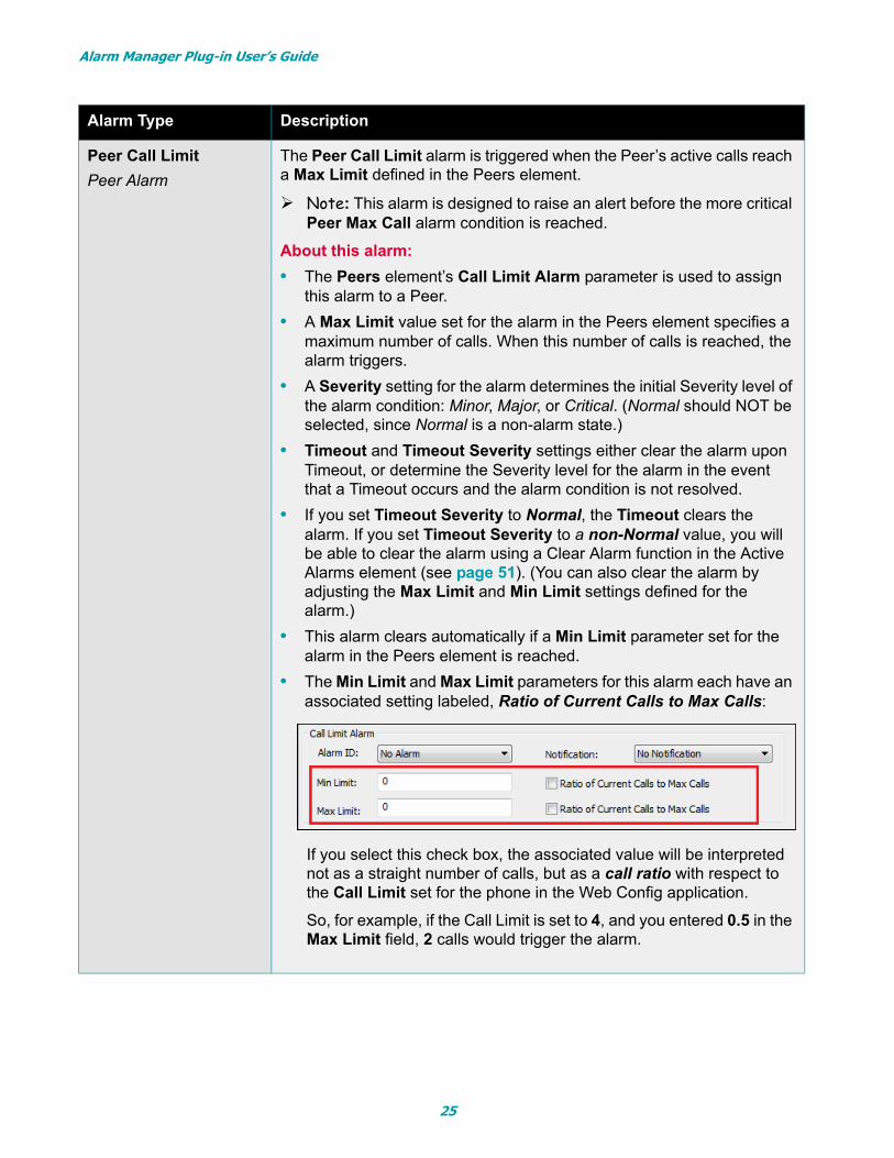
Peer Call Limit
Peer Alarm
The Peer Call Limit alarm is triggered when the Peer’s active calls reach a Max Limit defined in the Peers element.
Note: This alarm is designed to raise an alert before the more critical Peer Max Call alarm condition is reached.
About this alarm:
• The Peers element’s Call Limit Alarm parameter is used to assign this alarm to a Peer.
• A Max Limit value set for the alarm in the Peers element specifies a maximum number of calls. When this number of calls is reached, the alarm triggers.
• A Severity setting for the alarm determines the initial Severity level of the alarm condition: Minor, Major, or Critical. (Normal should NOT be selected, since Normal is a non-alarm state.)
• Timeout and Timeout Severity settings either clear the alarm upon Timeout, or determine the Severity level for the alarm in the event that a Timeout occurs and the alarm condition is not resolved.
• If you set Timeout Severity to Normal, the Timeout clears the alarm. If you set Timeout Severity to a non-Normal value, you will be able to clear the alarm using a Clear Alarm function in the Active Alarms element (see page 51). (You can also clear the alarm by adjusting the Max Limit and Min Limit settings defined for the alarm.)
• This alarm clears automatically if a Min Limit parameter set for the alarm in the Peers element is reached.
• The Min Limit and Max Limit parameters for this alarm each have an associated setting labeled, Ratio of Current Calls to Max Calls:
If you select this check box, the associated value will be interpreted not as a straight number of calls, but as a call ratio with respect to the Call Limit set for the phone in the Web Config application.
So, for example, if the Call Limit is set to 4, and you entered 0.5 in the Max Limit field, 2 calls would trigger the alarm.
Alarm Type Description
25
Alarm Manager Plug-in User’s Guide
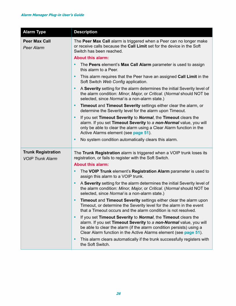
Peer Max Call
Peer Alarm
The Peer Max Call alarm is triggered when a Peer can no longer make or receive calls because the Call Limit set for the device in the Soft Switch has been reached.
About this alarm:
• The Peers element’s Max Call Alarm parameter is used to assign this alarm to a Peer.
• This alarm requires that the Peer have an assigned Call Limit in the Soft Switch Web Config application.
• A Severity setting for the alarm determines the initial Severity level of the alarm condition: Minor, Major, or Critical. (Normal should NOT be selected, since Normal is a non-alarm state.)
• Timeout and Timeout Severity settings either clear the alarm, or determine the Severity level for the alarm upon Timeout.
• If you set Timeout Severity to Normal, the Timeout clears the alarm. If you set Timeout Severity to a non-Normal value, you will only be able to clear the alarm using a Clear Alarm function in the Active Alarms element (see page 51).
• No system condition automatically clears this alarm.
Trunk Registration
VOIP Trunk AlarmThe Trunk Registration alarm is triggered when a VOIP trunk loses its registration, or fails to register with the Soft Switch.
About this alarm:
• The VOIP Trunk element’s Registration Alarm parameter is used to assign this alarm to a VOIP trunk.
• A Severity setting for the alarm determines the initial Severity level of the alarm condition: Minor, Major, or Critical. (Normal should NOT be selected, since Normal is a non-alarm state.)
• Timeout and Timeout Severity settings either clear the alarm upon Timeout, or determine the Severity level for the alarm in the event that a Timeout occurs and the alarm condition is not resolved.
• If you set Timeout Severity to Normal, the Timeout clears the alarm. If you set Timeout Severity to a non-Normal value, you will be able to clear the alarm (if the alarm condition persists) using a Clear Alarm function in the Active Alarms element (see page 51).
• This alarm clears automatically if the trunk successfully registers with the Soft Switch.
Alarm Type Description
26
Alarm Manager Plug-in User’s Guide
DAHDI Call Limit
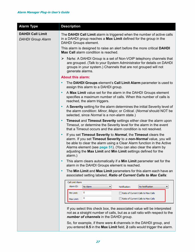
DAHDI Group AlarmThe DAHDI Call Limit alarm is triggered when the number of active calls in a DAHDI group reaches a Max Limit defined for the group in the DAHDI Groups element.
This alarm is designed to raise an alert before the more critical DAHDI Max Call alarm condition is reached.
Note: A DAHDI Group is a set of Non-VOIP telephony channels that are grouped. (Talk to your System Administrator for details on DAHDI groups in your system.) Channels that are not grouped will not generate alarms.
About this alarm:
• The DAHDI Groups element’s Call Limit Alarm parameter is used to assign this alarm to a DAHDI group.
• A Max Limit value set for the alarm in the DAHDI Groups element specifies a maximum number of calls. When this number of calls is reached, the alarm triggers.
• A Severity setting for the alarm determines the initial Severity level of the alarm condition: Minor, Major, or Critical. (Normal should NOT be selected, since Normal is a non-alarm state.)
• Timeout and Timeout Severity settings either clear the alarm upon Timeout, or determine the Severity level for the alarm in the event that a Timeout occurs and the alarm condition is not resolved.
• If you set Timeout Severity to Normal, the Timeout clears the alarm. If you set Timeout Severity to a non-Normal value, you will be able to clear the alarm using a Clear Alarm function in the Active Alarms element (see page 51). (You can also clear the alarm by adjusting the Max Limit and Min Limit settings defined for the alarm.)
• This alarm clears automatically if a Min Limit parameter set for the alarm in the DAHDI Groups element is reached.
• The Min Limit and Max Limit parameters for this alarm each have an associated setting labeled, Ratio of Current Calls to Max Calls:
If you select this check box, the associated value will be interpreted not as a straight number of calls, but as a call ratio with respect to the number of channels in the DAHDI group.
So, for example, if there were 4 channels in the DAHDI group, and you entered 0.5 in the Max Limit field, 2 calls would trigger the alarm.
Alarm Type Description
27
Alarm Manager Plug-in User’s Guide
DAHDI Max Call
DAHDI Group AlarmThe DAHDI Max Call alarm is triggered when the number of active calls is greater than or equal to the number of channels in the DAHDI group.
About this alarm:
• The DAHDI Groups element’s Max Call Alarm parameter is used to assign this alarm to a DAHDI group.
• A Severity setting for the alarm determines the initial Severity level of the alarm condition: Minor, Major, or Critical. (Normal should NOT be selected, since Normal is a non-alarm state.)
• Timeout and Timeout Severity settings either clear the alarm, or determine the Severity level for the alarm upon Timeout.
• If you set Timeout Severity to Normal, the Timeout clears the alarm. If you set Timeout Severity to a non-Normal value, you will be able to clear the alarm (if the alarm condition persists) using a Clear Alarm function in the Active Alarms element (see page 51).
• This alarm clears automatically if the number of active calls falls below the number of channels in the DAHDI group.
DAHDI State
DAHDI Group AlarmThe DAHDI State alarm is triggered when a T1 alarm is generated by the Soft Switch for any of the channels in the DAHDI group.
About this alarm:
• The DAHDI Groups element’s State Alarm parameter is used to assign this alarm to a DAHDI group.
• A Severity setting for the alarm determines the initial Severity level of the alarm condition: Minor, Major, or Critical. (Normal should NOT be selected, since Normal is a non-alarm state.)
• Timeout and Timeout Severity settings either clear the alarm, or determine the Severity level for the alarm upon Timeout.
• If you set Timeout Severity to Normal, the Timeout clears the alarm. If you set Timeout Severity to a non-Normal value, you will be able to clear the alarm (if the alarm condition persists) using a Clear Alarm function in the Active Alarms element (see page 51).
• This alarm clears automatically if a T1 alarm is no longer active for any channels in the DAHDI group.
Alarm Type Description
28
Alarm Manager Plug-in User’s Guide
Switch Connection
Switch AlarmThe Switch Connection alarm is triggered if the Soft Switch Monitor ser-vice loses its connection to the Soft Switch.
About this alarm:
• The Switches element’s Connection Alarm parameter is used to assign this alarm to the Soft Switch.
• A Severity setting for the alarm determines the initial Severity level of the alarm condition: Minor, Major, or Critical. (Normal should NOT be selected, since Normal is a non-alarm state.)
• Timeout and Timeout Severity settings either clear the alarm, or determine the Severity level for the alarm upon Timeout.
• If you set Timeout Severity to Normal, the Timeout clears the alarm. If you set Timeout Severity to a non-Normal value, you will be able to clear the alarm (if the alarm condition persists) using a Clear Alarm function in the Active Alarms element (see page 51).
• This alarm clears automatically if the connection between the Soft Switch Monitor service and Soft Switch is reestablished.
Alarm Type Description
29
Alarm Manager Plug-in User’s Guide
Grouping & Sorting Alarms in the Alarms Element
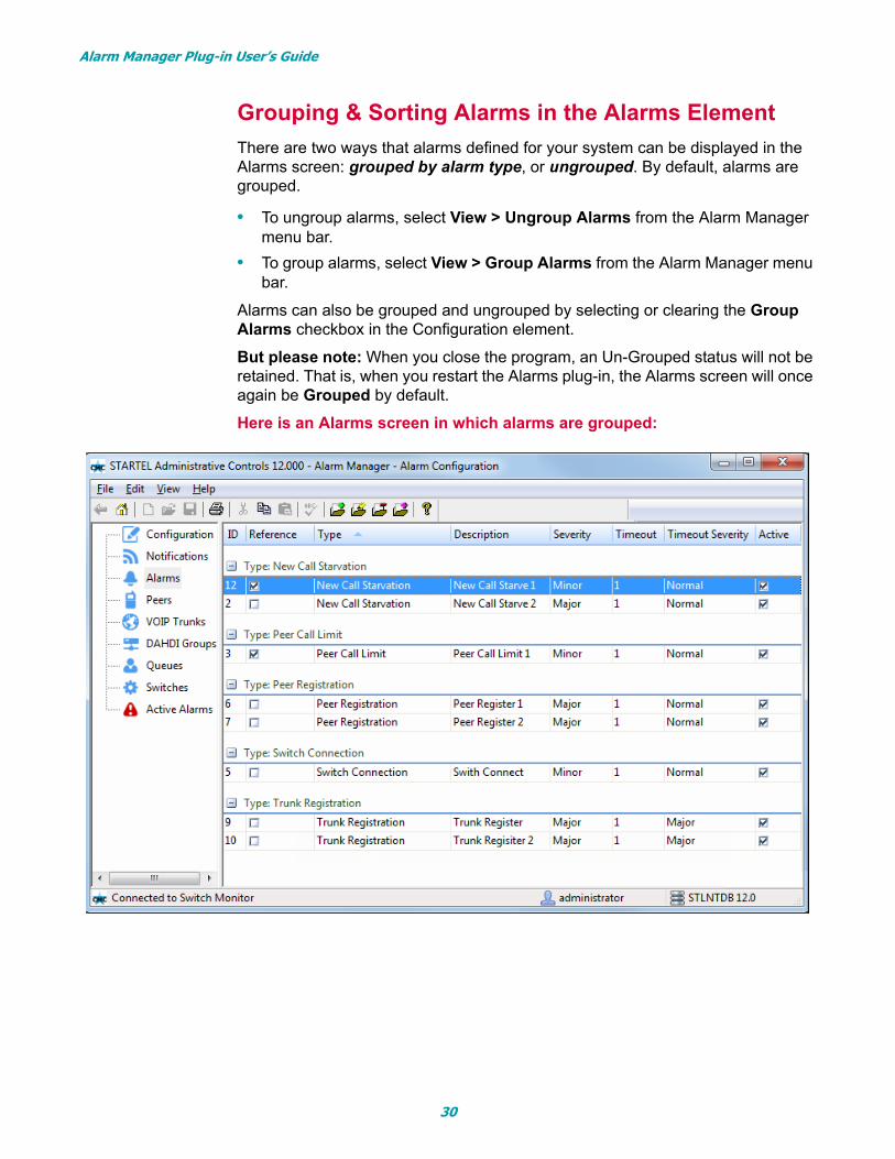
There are two ways that alarms defined for your system can be displayed in the Alarms screen: grouped by alarm type, or ungrouped. By default, alarms are grouped.
• To ungroup alarms, select View > Ungroup Alarms from the Alarm Manager menu bar.
• To group alarms, select View > Group Alarms from the Alarm Manager menu bar.
Alarms can also be grouped and ungrouped by selecting or clearing the Group Alarms checkbox in the Configuration element.
But please note: When you close the program, an Un-Grouped status will not be retained. That is, when you restart the Alarms plug-in, the Alarms screen will once again be Grouped by default.
Here is an Alarms screen in which alarms are grouped:
30
Alarm Manager Plug-in User’s Guide
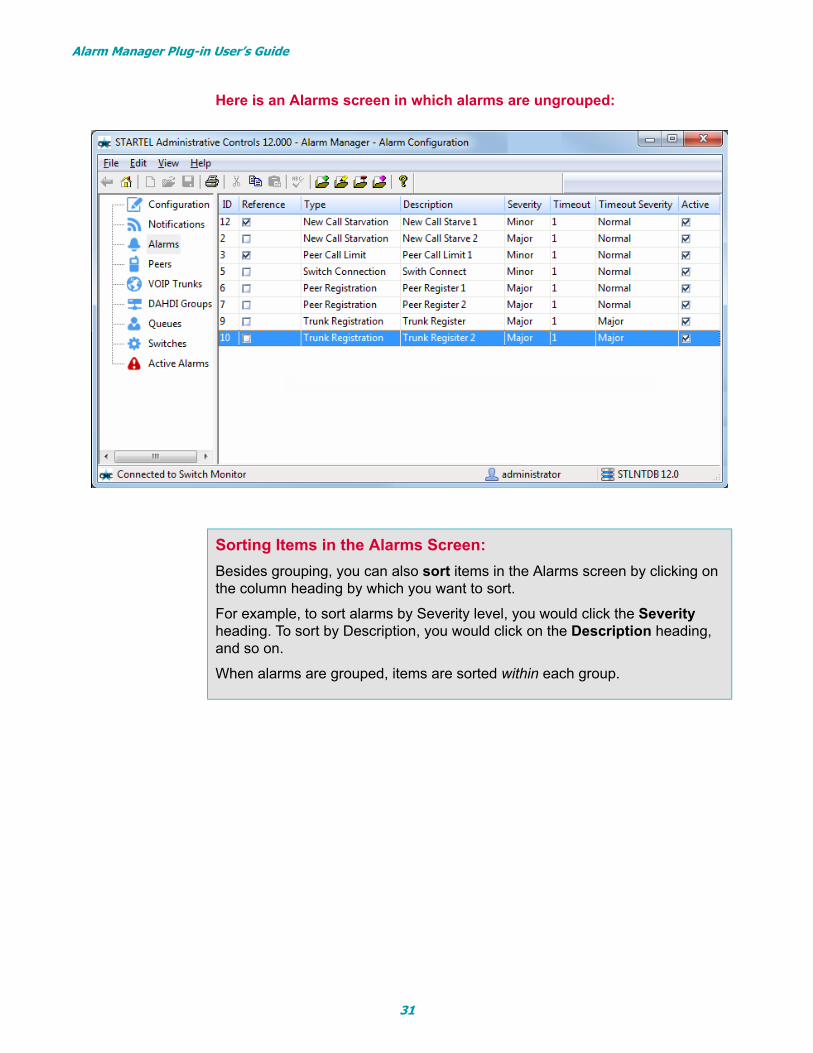
Here is an Alarms screen in which alarms are ungrouped:
Sorting Items in the Alarms Screen:
Besides grouping, you can also sort items in the Alarms screen by clicking on the column heading by which you want to sort.
For example, to sort alarms by Severity level, you would click the Severity heading. To sort by Description, you would click on the Description heading, and so on.
When alarms are grouped, items are sorted within each group.
31
Alarm Manager Plug-in User’s Guide
Editing, Removing, and Copying Alarms
If you want to edit, delete, or copy an alarm after it’s been defined, you can do it in the Alarms element. And this will be true even if you added the alarm using one of the other elements.
But note: To edit, remove, or copy an alarm assignment, or to edit alarm param-eters that are not configurable in the Alarms element (for example, Starve Time Queue alarm parameters) you will need to use the element in which the assign-ment was made.
See the topics that follow for more information:
Editing an Alarm Definition in the Alarms Element (below)
Removing an Alarm in the Alarms Element (page 33)
Copying an Alarm in the Alarms Element (page 34)
Editing an Alarm Definition in the Alarms Element
Follow these steps to edit an alarm definition in the Alarms element:
1 Display the Alarms screen.
2 Double-click the alarm you want to edit (or select the alarm, then click (Edit) on the AC toolbar).
3 When the Alarm Configuration dialog box opens, make necessary changes.
4 Click Save to save and close.
NOTES:
If you edit an alarm that has already been assigned to one of more system components, the change(s) will be applied wherever the alarm is assigned.
If you want to edit an alarm definition only for a particular alarm assignment, you’ll need to make the edit in the element associated with the assignment.
32
Alarm Manager Plug-in User’s Guide
Removing an Alarm in the Alarms Element
You can remove an alarm that has been defined for your system using the Remove feature on the Alarm element toolbar. However, before you can remove an alarm that has been assigned to a system component, you need to delete the alarm assignment in the associated element. If you attempt to remove an alarm that is currently assigned, a screen will display to show you where the alarm is assigned, and instruct you to remove the assignment(s).
Follow these steps to remove an alarm from the Alarms element:
1 Display the Alarms screen.
2 Select the alarm you want to remove.
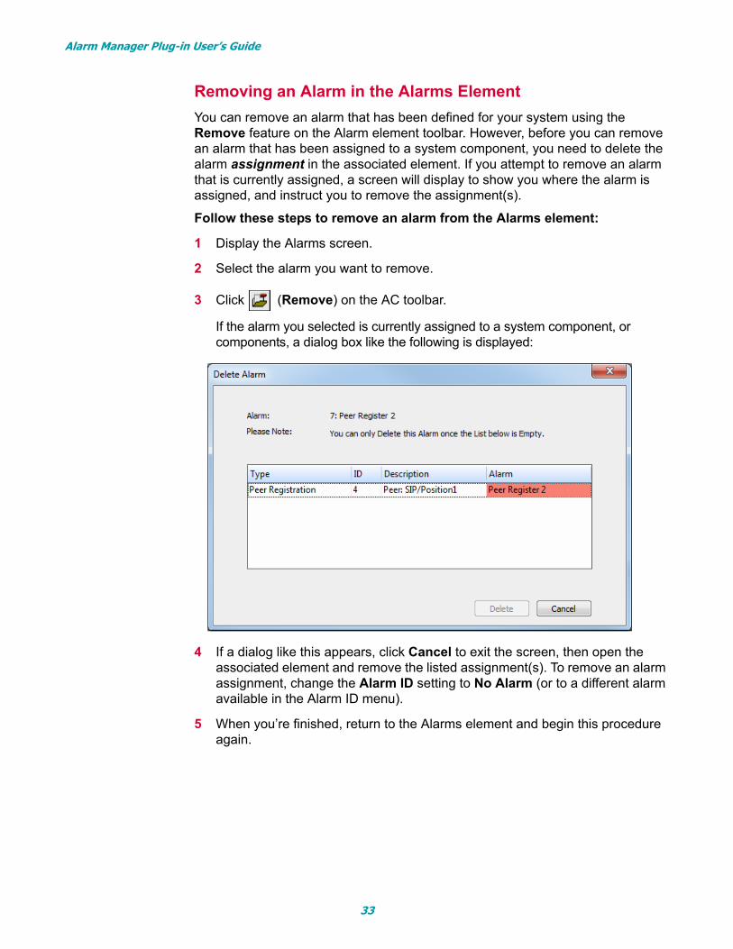
3 Click (Remove) on the AC toolbar.
If the alarm you selected is currently assigned to a system component, or components, a dialog box like the following is displayed:
4 If a dialog like this appears, click Cancel to exit the screen, then open the associated element and remove the listed assignment(s). To remove an alarm assignment, change the Alarm ID setting to No Alarm (or to a different alarm available in the Alarm ID menu).
5 When you’re finished, return to the Alarms element and begin this procedure again.
33
Alarm Manager Plug-in User’s Guide
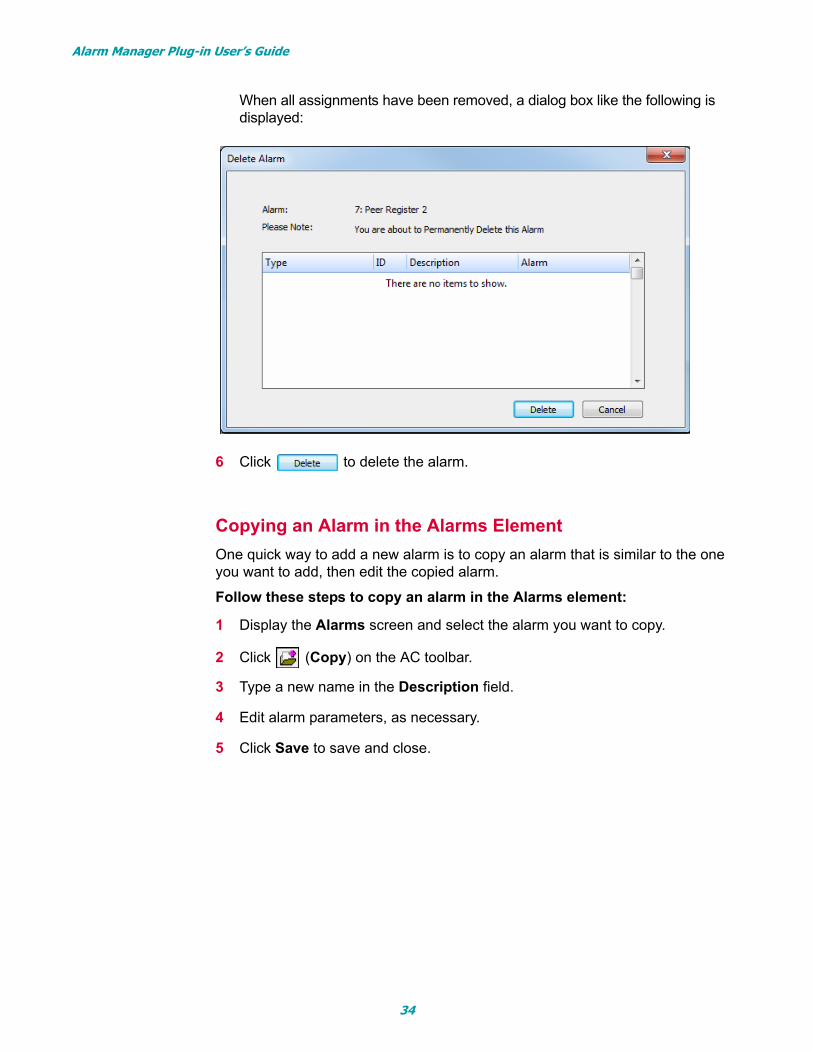
When all assignments have been removed, a dialog box like the following is displayed:
6 Click to delete the alarm.
Copying an Alarm in the Alarms Element
One quick way to add a new alarm is to copy an alarm that is similar to the one you want to add, then edit the copied alarm.
Follow these steps to copy an alarm in the Alarms element:
1 Display the Alarms screen and select the alarm you want to copy.
2 Click (Copy) on the AC toolbar.
3 Type a new name in the Description field.
4 Edit alarm parameters, as necessary.
5 Click Save to save and close.
34
Alarm Manager Plug-in User’s Guide
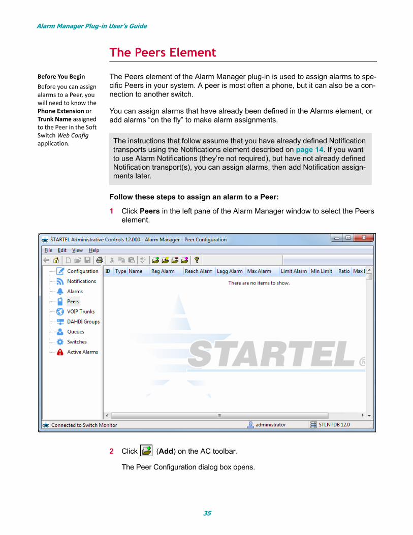
The Peers Element
The Peers element of the Alarm Manager plug-in is used to assign alarms to spe-cific Peers in your system. A peer is most often a phone, but it can also be a con-nection to another switch.
You can assign alarms that have already been defined in the Alarms element, or add alarms “on the fly” to make alarm assignments.
Follow these steps to assign an alarm to a Peer:
1 Click Peers in the left pane of the Alarm Manager window to select the Peers element.
2 Click (Add) on the AC toolbar.
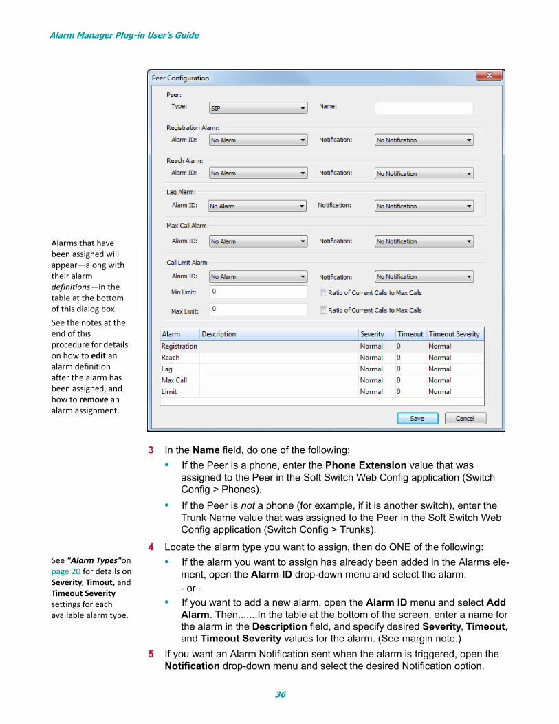
The Peer Configuration dialog box opens.
The instructions that follow assume that you have already defined Notification transports using the Notifications element described on page 14. If you want to use Alarm Notifications (they’re not required), but have not already defined Notification transport(s), you can assign alarms, then add Notification assign-ments later.
Before You Begin Before you can assign alarms to a Peer, you will need to know the Phone Extension or Trunk Name assigned to the Peer in the Soft Switch Web Config application.
35
Alarm Manager Plug-in User’s Guide
3 In the Name field, do one of the following:
• If the Peer is a phone, enter the Phone Extension value that was assigned to the Peer in the Soft Switch Web Config application (Switch Config > Phones).
• If the Peer is not a phone (for example, if it is another switch), enter the Trunk Name value that was assigned to the Peer in the Soft Switch Web Config application (Switch Config > Trunks).
4 Locate the alarm type you want to assign, then do ONE of the following:
• If the alarm you want to assign has already been added in the Alarms ele-ment, open the Alarm ID drop-down menu and select the alarm. - or -
• If you want to add a new alarm, open the Alarm ID menu and select Add Alarm. Then.......In the table at the bottom of the screen, enter a name for the alarm in the Description field, and specify desired Severity, Timeout, and Timeout Severity values for the alarm. (See margin note.)
5 If you want an Alarm Notification sent when the alarm is triggered, open the Notification drop-down menu and select the desired Notification option.
Alarms that have been assigned will appear—along with their alarm definitions—in the table at the bottom of this dialog box. See the notes at the end of this procedure for details on how to edit an alarm definition after the alarm has been assigned, and how to remove an alarm assignment.
See "Alarm Types"on page 20 for details on Severity, Timout, and Timeout Severity settings for each available alarm type.
36
Alarm Manager Plug-in User’s Guide
6 If the alarm is a Call Limit alarm, specify additional parameters (Min Limit, Max Limit, etc.) as described on page 25.
7 Repeat Steps 2-6 for each alarm type that you want to assign to the Peer.
Note: Only one alarm of each type can be assigned.
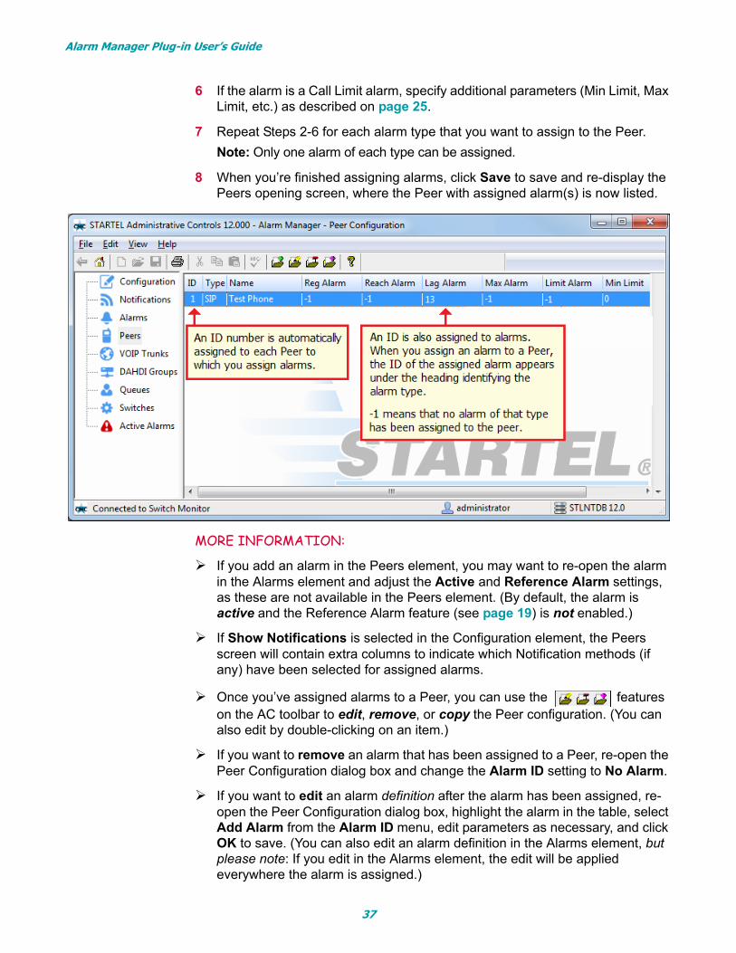
8 When you’re finished assigning alarms, click Save to save and re-display the Peers opening screen, where the Peer with assigned alarm(s) is now listed.
MORE INFORMATION:
If you add an alarm in the Peers element, you may want to re-open the alarm in the Alarms element and adjust the Active and Reference Alarm settings, as these are not available in the Peers element. (By default, the alarm is active and the Reference Alarm feature (see page 19) is not enabled.)
If Show Notifications is selected in the Configuration element, the Peers screen will contain extra columns to indicate which Notification methods (if any) have been selected for assigned alarms.
Once you’ve assigned alarms to a Peer, you can use the features on the AC toolbar to edit, remove, or copy the Peer configuration. (You can also edit by double-clicking on an item.)
If you want to remove an alarm that has been assigned to a Peer, re-open the Peer Configuration dialog box and change the Alarm ID setting to No Alarm.
If you want to edit an alarm definition after the alarm has been assigned, re-open the Peer Configuration dialog box, highlight the alarm in the table, select Add Alarm from the Alarm ID menu, edit parameters as necessary, and click OK to save. (You can also edit an alarm definition in the Alarms element, but please note: If you edit in the Alarms element, the edit will be applied everywhere the alarm is assigned.)
37
Alarm Manager Plug-in User’s Guide
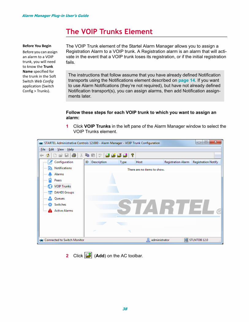
The VOIP Trunks Element
The VOIP Trunk element of the Startel Alarm Manager allows you to assign a Registration Alarm to a VOIP trunk. A Registration alarm is an alarm that will acti-vate in the event that a VOIP trunk loses its registration, or if the initial registration fails.
Follow these steps for each VOIP trunk to which you want to assign an alarm:
1 Click VOIP Trunks in the left pane of the Alarm Manager window to select the VOIP Trunks element.
2 Click (Add) on the AC toolbar.
The instructions that follow assume that you have already defined Notification transports using the Notifications element described on page 14. If you want to use Alarm Notifications (they’re not required), but have not already defined Notification transport(s), you can assign alarms, then add Notification assign-ments later.
Before You Begin Before you can assign an alarm to a VOIP trunk, you will need to know the Trunk Name specified for the trunk in the Soft Switch Web Config application (Switch Config > Trunks).
38
Alarm Manager Plug-in User’s Guide
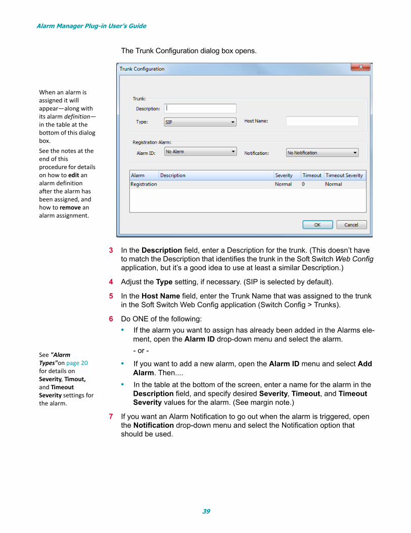
The Trunk Configuration dialog box opens.
3 In the Description field, enter a Description for the trunk. (This doesn’t have to match the Description that identifies the trunk in the Soft Switch Web Config application, but it’s a good idea to use at least a similar Description.)
4 Adjust the Type setting, if necessary. (SIP is selected by default).
5 In the Host Name field, enter the Trunk Name that was assigned to the trunk in the Soft Switch Web Config application (Switch Config > Trunks).
6 Do ONE of the following:
• If the alarm you want to assign has already been added in the Alarms ele-ment, open the Alarm ID drop-down menu and select the alarm.
- or -
• If you want to add a new alarm, open the Alarm ID menu and select Add Alarm. Then....
• In the table at the bottom of the screen, enter a name for the alarm in the Description field, and specify desired Severity, Timeout, and Timeout Severity values for the alarm. (See margin note.)
7 If you want an Alarm Notification to go out when the alarm is triggered, open the Notification drop-down menu and select the Notification option that should be used.
When an alarm is assigned it will appear—along with its alarm definition—in the table at the bottom of this dialog box. See the notes at the end of this procedure for details on how to edit an alarm definition after the alarm has been assigned, and how to remove an alarm assignment.
See "Alarm Types"on page 20 for details on Severity, Timout, and Timeout Severity settings for the alarm.
39
Alarm Manager Plug-in User’s Guide
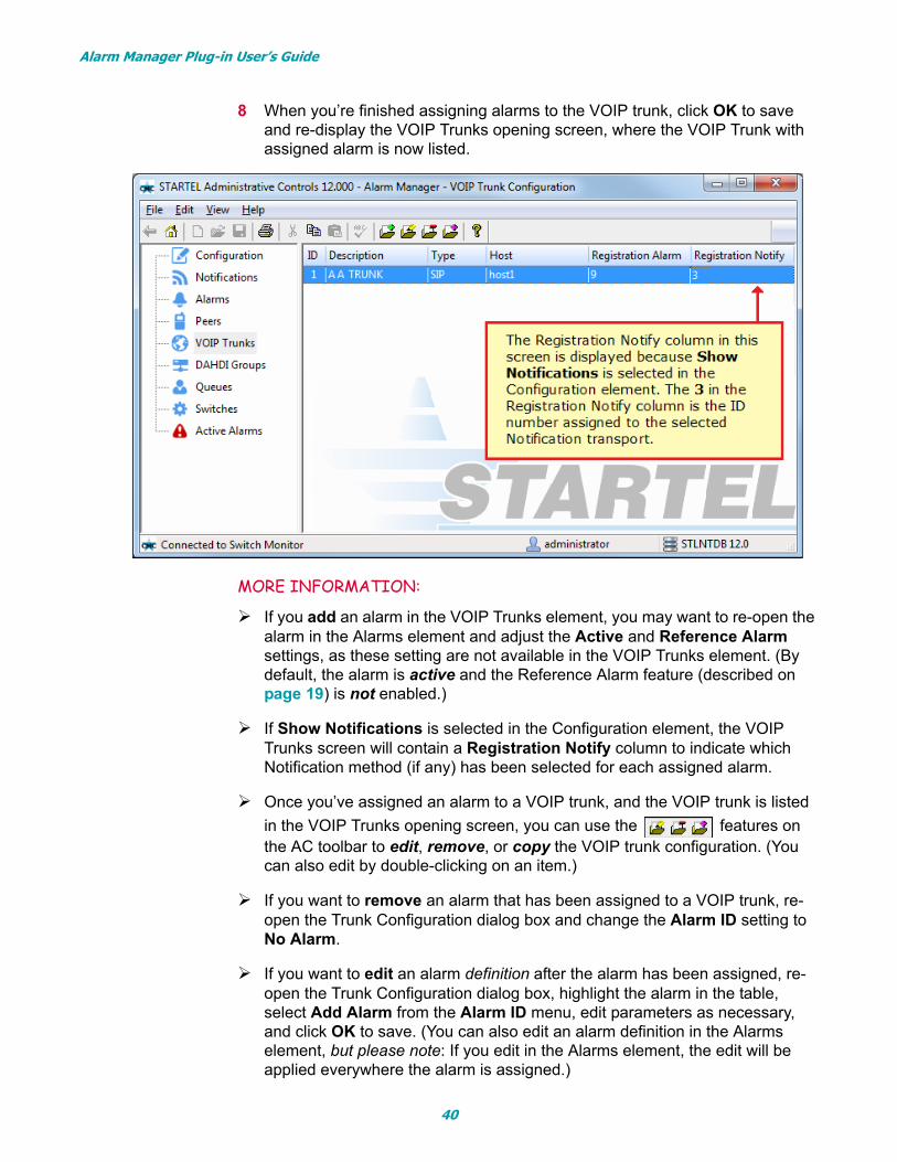
8 When you’re finished assigning alarms to the VOIP trunk, click OK to save and re-display the VOIP Trunks opening screen, where the VOIP Trunk with assigned alarm is now listed.
MORE INFORMATION:
If you add an alarm in the VOIP Trunks element, you may want to re-open the alarm in the Alarms element and adjust the Active and Reference Alarm settings, as these setting are not available in the VOIP Trunks element. (By default, the alarm is active and the Reference Alarm feature (described on page 19) is not enabled.)
If Show Notifications is selected in the Configuration element, the VOIP Trunks screen will contain a Registration Notify column to indicate which Notification method (if any) has been selected for each assigned alarm.
Once you’ve assigned an alarm to a VOIP trunk, and the VOIP trunk is listed
in the VOIP Trunks opening screen, you can use the features on the AC toolbar to edit, remove, or copy the VOIP trunk configuration. (You can also edit by double-clicking on an item.)
If you want to remove an alarm that has been assigned to a VOIP trunk, re-open the Trunk Configuration dialog box and change the Alarm ID setting to No Alarm.
If you want to edit an alarm definition after the alarm has been assigned, re-open the Trunk Configuration dialog box, highlight the alarm in the table, select Add Alarm from the Alarm ID menu, edit parameters as necessary, and click OK to save. (You can also edit an alarm definition in the Alarms element, but please note: If you edit in the Alarms element, the edit will be applied everywhere the alarm is assigned.)
40
Alarm Manager Plug-in User’s Guide
The DAHDI Groups Element
The DAHDI Groups element of the Alarm Manager plug-in is used to assign alarms to a group of DAHDI channels in your system. (A DAHDI channel is a non-VOIP telephony channel.) You can assign alarms that have already been defined in the Alarms element, or add alarms “on the fly” to make alarm assignments.
Follow these steps to assign an alarms to a DAHDI Group:
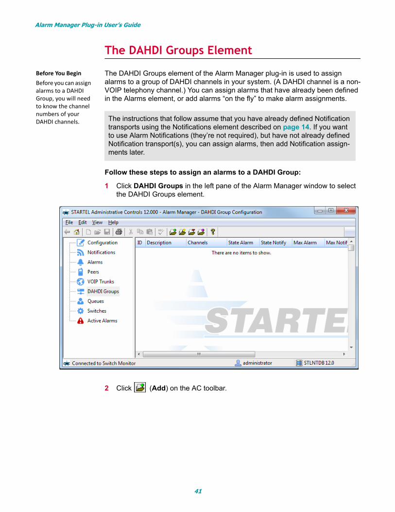
1 Click DAHDI Groups in the left pane of the Alarm Manager window to select the DAHDI Groups element.
2 Click (Add) on the AC toolbar.
The instructions that follow assume that you have already defined Notification transports using the Notifications element described on page 14. If you want to use Alarm Notifications (they’re not required), but have not already defined Notification transport(s), you can assign alarms, then add Notification assign-ments later.
Before You Begin Before you can assign alarms to a DAHDI Group, you will need to know the channel numbers of your DAHDI channels.
41
Alarm Manager Plug-in User’s Guide
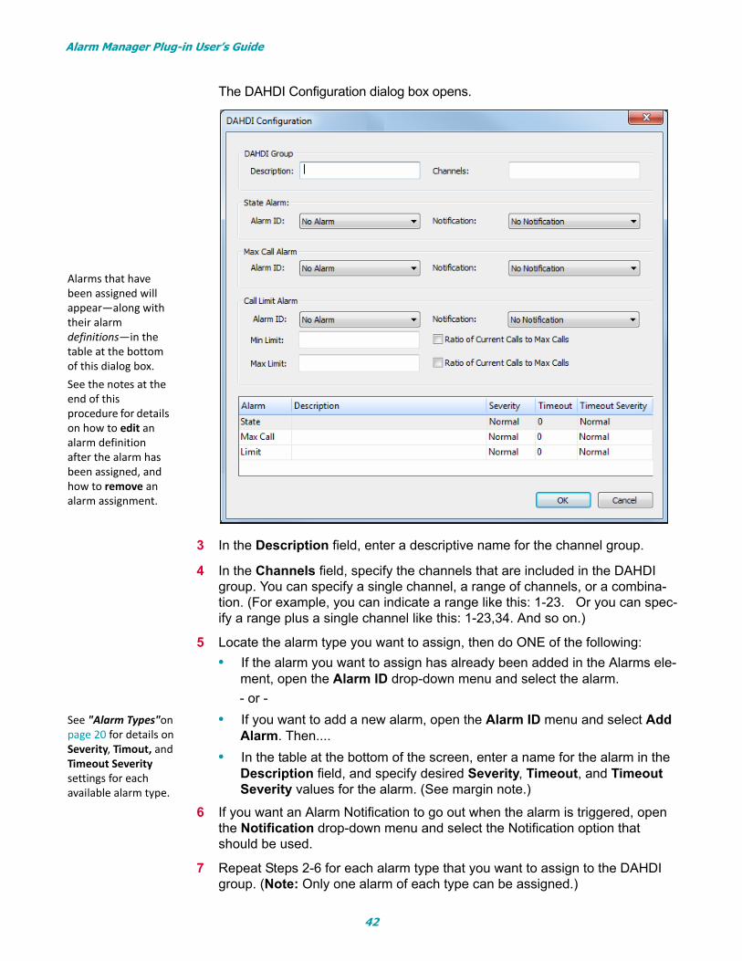
The DAHDI Configuration dialog box opens.
3 In the Description field, enter a descriptive name for the channel group.
4 In the Channels field, specify the channels that are included in the DAHDI group. You can specify a single channel, a range of channels, or a combina-tion. (For example, you can indicate a range like this: 1-23. Or you can spec-ify a range plus a single channel like this: 1-23,34. And so on.)
5 Locate the alarm type you want to assign, then do ONE of the following:
• If the alarm you want to assign has already been added in the Alarms ele-ment, open the Alarm ID drop-down menu and select the alarm.
- or -
• If you want to add a new alarm, open the Alarm ID menu and select Add Alarm. Then....
• In the table at the bottom of the screen, enter a name for the alarm in the Description field, and specify desired Severity, Timeout, and Timeout Severity values for the alarm. (See margin note.)
6 If you want an Alarm Notification to go out when the alarm is triggered, open the Notification drop-down menu and select the Notification option that should be used.
7 Repeat Steps 2-6 for each alarm type that you want to assign to the DAHDI group. (Note: Only one alarm of each type can be assigned.)
Alarms that have been assigned will appear—along with their alarm definitions—in the table at the bottom of this dialog box. See the notes at the end of this procedure for details on how to edit an alarm definition after the alarm has been assigned, and how to remove an alarm assignment.
See "Alarm Types"on page 20 for details on Severity, Timout, and Timeout Severity settings for each available alarm type.
42
Alarm Manager Plug-in User’s Guide
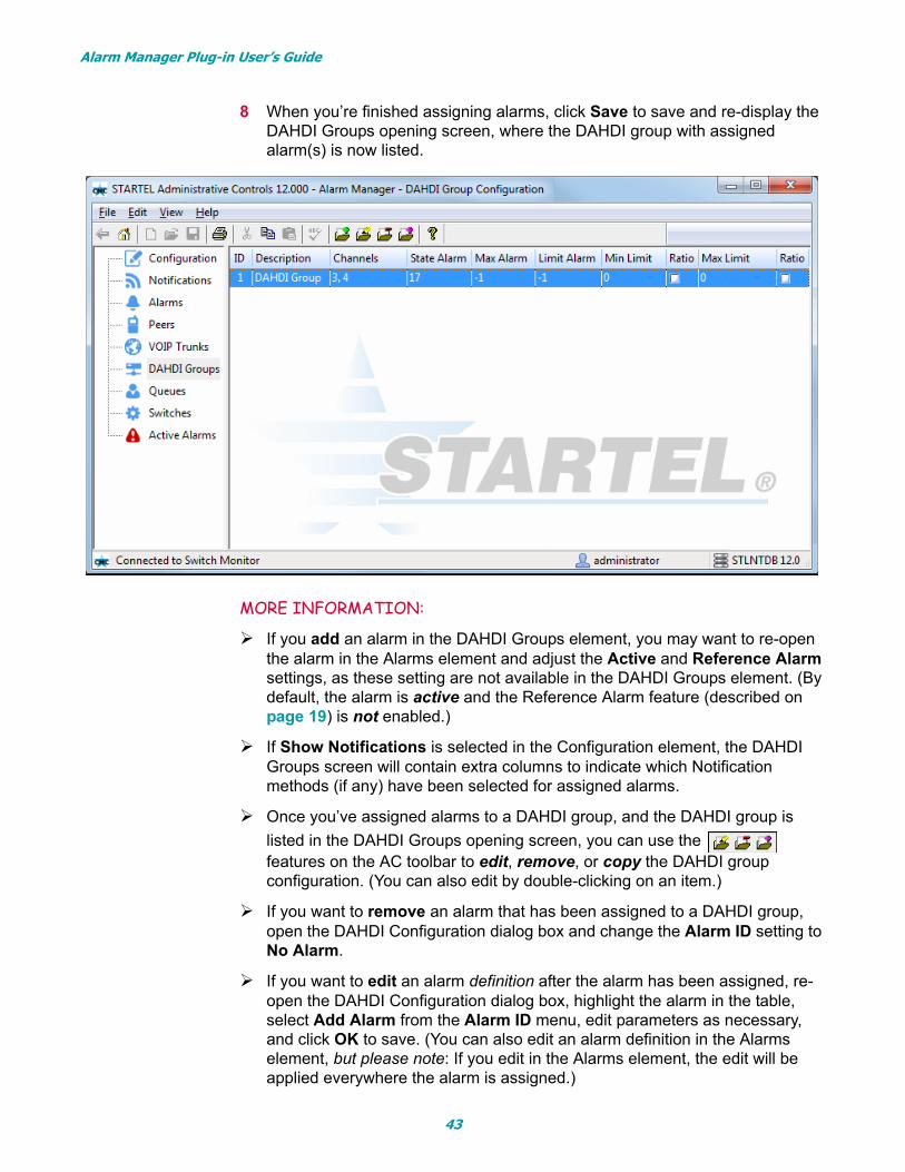
8 When you’re finished assigning alarms, click Save to save and re-display the DAHDI Groups opening screen, where the DAHDI group with assigned alarm(s) is now listed.
MORE INFORMATION:
If you add an alarm in the DAHDI Groups element, you may want to re-open the alarm in the Alarms element and adjust the Active and Reference Alarm settings, as these setting are not available in the DAHDI Groups element. (By default, the alarm is active and the Reference Alarm feature (described on page 19) is not enabled.)
If Show Notifications is selected in the Configuration element, the DAHDI Groups screen will contain extra columns to indicate which Notification methods (if any) have been selected for assigned alarms.
Once you’ve assigned alarms to a DAHDI group, and the DAHDI group is
listed in the DAHDI Groups opening screen, you can use the features on the AC toolbar to edit, remove, or copy the DAHDI group configuration. (You can also edit by double-clicking on an item.)
If you want to remove an alarm that has been assigned to a DAHDI group, open the DAHDI Configuration dialog box and change the Alarm ID setting to No Alarm.
If you want to edit an alarm definition after the alarm has been assigned, re-open the DAHDI Configuration dialog box, highlight the alarm in the table, select Add Alarm from the Alarm ID menu, edit parameters as necessary, and click OK to save. (You can also edit an alarm definition in the Alarms element, but please note: If you edit in the Alarms element, the edit will be applied everywhere the alarm is assigned.)
43
Alarm Manager Plug-in User’s Guide
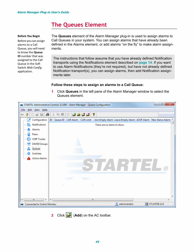
The Queues Element
The Queues element of the Alarm Manager plug-in is used to assign alarms to Call Queues in your system. You can assign alarms that have already been defined in the Alarms element, or add alarms “on the fly” to make alarm assign-ments.
Follow these steps to assign an alarms to a Call Queue:
1 Click Queues in the left pane of the Alarm Manager window to select the Queues element.
2 Click (Add) on the AC toolbar.
The instructions that follow assume that you have already defined Notification transports using the Notifications element described on page 14. If you want to use Alarm Notifications (they’re not required), but have not already defined Notification transport(s), you can assign alarms, then add Notification assign-ments later.
Before You Begin Before you can assign alarms to a Call Queue, you will need to know the Queue ID number that was assigned to the Call Queue in the Soft Switch Web Config application.
44
Alarm Manager Plug-in User’s Guide
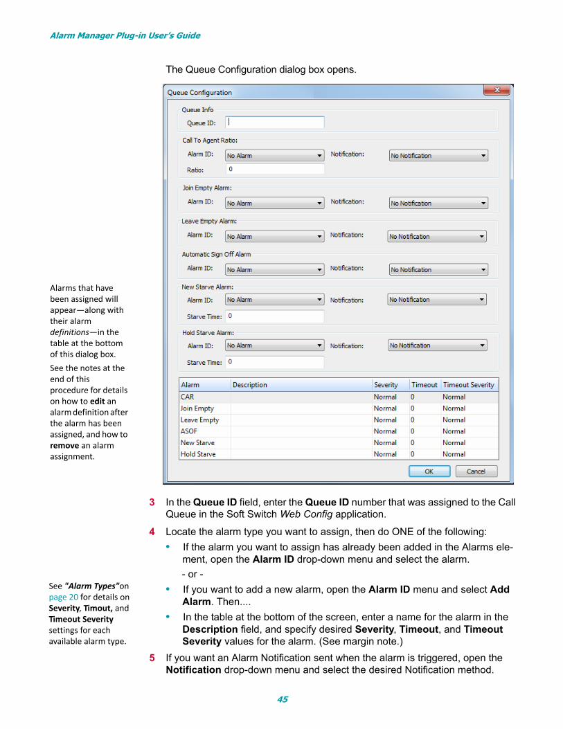
The Queue Configuration dialog box opens.
3 In the Queue ID field, enter the Queue ID number that was assigned to the Call Queue in the Soft Switch Web Config application.
4 Locate the alarm type you want to assign, then do ONE of the following:
• If the alarm you want to assign has already been added in the Alarms ele-ment, open the Alarm ID drop-down menu and select the alarm.
- or -
• If you want to add a new alarm, open the Alarm ID menu and select Add Alarm. Then....
• In the table at the bottom of the screen, enter a name for the alarm in the Description field, and specify desired Severity, Timeout, and Timeout Severity values for the alarm. (See margin note.)
5 If you want an Alarm Notification sent when the alarm is triggered, open the Notification drop-down menu and select the desired Notification method.
Alarms that have been assigned will appear—along with their alarm definitions—in the table at the bottom of this dialog box. See the notes at the end of this procedure for details on how to edit an alarm definition after the alarm has been assigned, and how to remove an alarm assignment.
See "Alarm Types"on page 20 for details on Severity, Timout, and Timeout Severity settings for each available alarm type.
45
Alarm Manager Plug-in User’s Guide
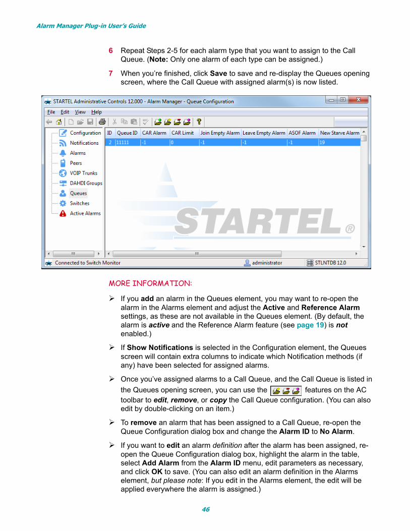
6 Repeat Steps 2-5 for each alarm type that you want to assign to the Call Queue. (Note: Only one alarm of each type can be assigned.)
7 When you’re finished, click Save to save and re-display the Queues opening screen, where the Call Queue with assigned alarm(s) is now listed.
MORE INFORMATION:
If you add an alarm in the Queues element, you may want to re-open the alarm in the Alarms element and adjust the Active and Reference Alarm settings, as these are not available in the Queues element. (By default, the alarm is active and the Reference Alarm feature (see page 19) is not enabled.)
If Show Notifications is selected in the Configuration element, the Queues screen will contain extra columns to indicate which Notification methods (if any) have been selected for assigned alarms.
Once you’ve assigned alarms to a Call Queue, and the Call Queue is listed in
the Queues opening screen, you can use the features on the AC toolbar to edit, remove, or copy the Call Queue configuration. (You can also edit by double-clicking on an item.)
To remove an alarm that has been assigned to a Call Queue, re-open the Queue Configuration dialog box and change the Alarm ID to No Alarm.
If you want to edit an alarm definition after the alarm has been assigned, re-open the Queue Configuration dialog box, highlight the alarm in the table, select Add Alarm from the Alarm ID menu, edit parameters as necessary, and click OK to save. (You can also edit an alarm definition in the Alarms element, but please note: If you edit in the Alarms element, the edit will be applied everywhere the alarm is assigned.)
46
Alarm Manager Plug-in User’s Guide
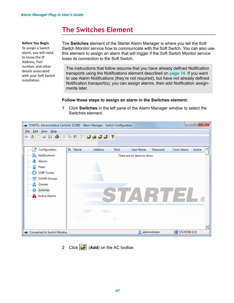
The Switches Element
The Switches element of the Startel Alarm Manager is where you tell the Soft Switch Monitor service how to communicate with the Soft Switch. You can also use this element to assign an alarm that will trigger if the Soft Switch Monitor service loses its connection to the Soft Switch.
Follow these steps to assign an alarm in the Switches element:
1 Click Switches in the left pane of the Alarm Manager window to select the Switches element.
2 Click (Add) on the AC toolbar.
The instructions that follow assume that you have already defined Notification transports using the Notifications element described on page 14. If you want to use Alarm Notifications (they’re not required), but have not already defined Notification transport(s), you can assign alarms, then add Notification assign-ments later.
Before You Begin To assign a Switch alarm, you will need to know the IP Address, Port number, and other details associated with your Soft Switch installation.
47
Alarm Manager Plug-in User’s Guide
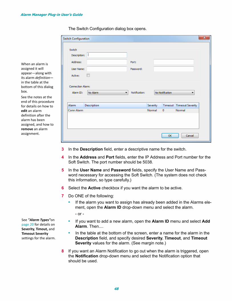
The Switch Configuration dialog box opens.
3 In the Description field, enter a descriptive name for the switch.
4 In the Address and Port fields, enter the IP Address and Port number for the Soft Switch. The port number should be 5038.
5 In the User Name and Password fields, specify the User Name and Pass-word necessary for accessing the Soft Switch. (The system does not check this information, so type carefully.)
6 Select the Active checkbox if you want the alarm to be active.
7 Do ONE of the following:
• If the alarm you want to assign has already been added in the Alarms ele-ment, open the Alarm ID drop-down menu and select the alarm.
- or -
• If you want to add a new alarm, open the Alarm ID menu and select Add Alarm. Then....
• In the table at the bottom of the screen, enter a name for the alarm in the Description field, and specify desired Severity, Timeout, and Timeout Severity values for the alarm. (See margin note.)
8 If you want an Alarm Notification to go out when the alarm is triggered, open the Notification drop-down menu and select the Notification option that should be used.
When an alarm is assigned it will appear—along with its alarm definition—in the table at the bottom of this dialog box. See the notes at the end of this procedure for details on how to edit an alarm definition after the alarm has been assigned, and how to remove an alarm assignment.
See "Alarm Types"on page 20 for details on Severity, Timout, and Timeout Severity settings for the alarm.
48
Alarm Manager Plug-in User’s Guide
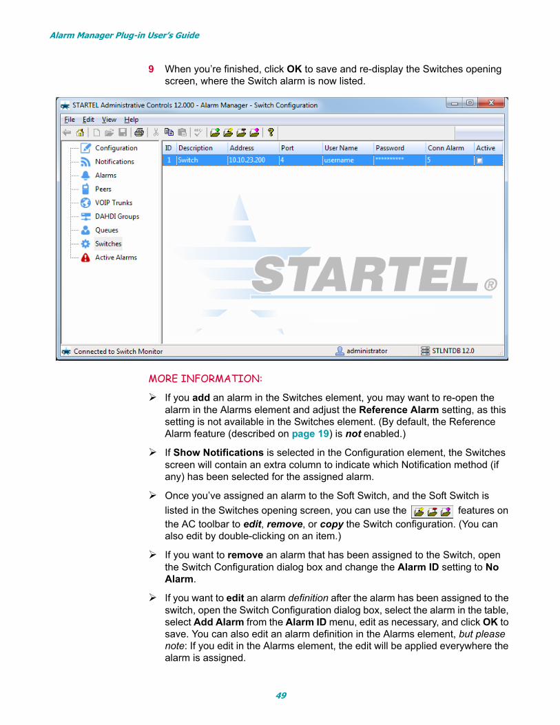
9 When you’re finished, click OK to save and re-display the Switches opening screen, where the Switch alarm is now listed.
MORE INFORMATION:
If you add an alarm in the Switches element, you may want to re-open the alarm in the Alarms element and adjust the Reference Alarm setting, as this setting is not available in the Switches element. (By default, the Reference Alarm feature (described on page 19) is not enabled.)
If Show Notifications is selected in the Configuration element, the Switches screen will contain an extra column to indicate which Notification method (if any) has been selected for the assigned alarm.
Once you’ve assigned an alarm to the Soft Switch, and the Soft Switch is
listed in the Switches opening screen, you can use the features on the AC toolbar to edit, remove, or copy the Switch configuration. (You can also edit by double-clicking on an item.)
If you want to remove an alarm that has been assigned to the Switch, open the Switch Configuration dialog box and change the Alarm ID setting to No Alarm.
If you want to edit an alarm definition after the alarm has been assigned to the switch, open the Switch Configuration dialog box, select the alarm in the table, select Add Alarm from the Alarm ID menu, edit as necessary, and click OK to save. You can also edit an alarm definition in the Alarms element, but please note: If you edit in the Alarms element, the edit will be applied everywhere the alarm is assigned.
49
Alarm Manager Plug-in User’s Guide
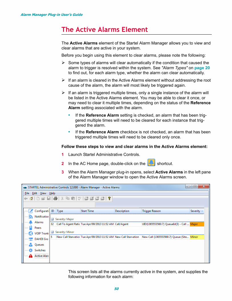
The Active Alarms Element
The Active Alarms element of the Startel Alarm Manager allows you to view and clear alarms that are active in your system.
Before you begin using this element to clear alarms, please note the following:
Some types of alarms will clear automatically if the condition that caused the alarm to trigger is resolved within the system. See "Alarm Types" on page 20 to find out, for each alarm type, whether the alarm can clear automatically.
If an alarm is cleared in the Active Alarms element without addressing the root cause of the alarm, the alarm will most likely be triggered again.
If an alarm is triggered multiple times, only a single instance of the alarm will be listed in the Active Alarms element. You may be able to clear it once, or may need to clear it multiple times, depending on the status of the Reference Alarm setting associated with the alarm.
• If the Reference Alarm setting is checked, an alarm that has been trig-gered multiple times will need to be cleared for each instance that trig-gered the alarm.
• If the Reference Alarm checkbox is not checked, an alarm that has been triggered multiple times will need to be cleared only once.
Follow these steps to view and clear alarms in the Active Alarms element:
1 Launch Startel Administrative Controls.
2 In the AC Home page, double-click on the shortcut.
3 When the Alarm Manager plug-in opens, select Active Alarms in the left pane of the Alarm Manager window to open the Active Alarms screen.
This screen lists all the alarms currently active in the system, and supplies the following information for each alarm:
50
Alarm Manager Plug-in User’s Guide
• The Alarm ID (assigned when alarm was added/defined)
• The Alarm Type
• The Alarm Start Time (time the alarm was triggered)
• The Alarm Description (assigned when alarm was added/defined)
• The Trigger Reason associated with the alarm
• The Alarm Severity
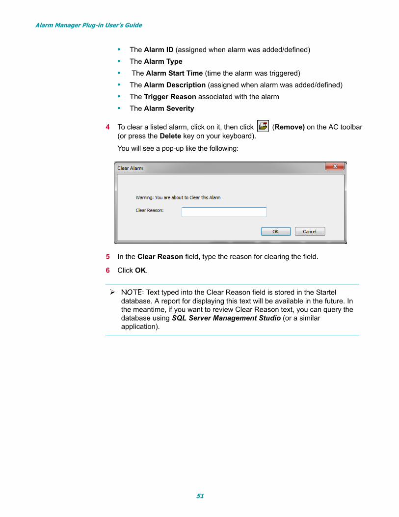
4 To clear a listed alarm, click on it, then click (Remove) on the AC toolbar (or press the Delete key on your keyboard).
You will see a pop-up like the following:
5 In the Clear Reason field, type the reason for clearing the field.
6 Click OK.
NOTE: Text typed into the Clear Reason field is stored in the Startel database. A report for displaying this text will be available in the future. In the meantime, if you want to review Clear Reason text, you can query the database using SQL Server Management Studio (or a similar application).
51
IndexAactivating alarms 19Active Alarms element 50Active checkbox 19adding alarms in the Alarms element 17Alarm Configuration dialog box 18alarm definition
editing after it’s been assigned 37, 40, 43, 46, 49Alarm Manager
general road map for using 10Alarm Manager element summary 9Alarm Manager elements 9
Active Alarms element 50Alarms element 17Configuration element 12DAHDI Groups element 41Notifications element 14Peers element 35Queues element 44Summary information 9Switches element 47VOIP Trunks element 38
Alarm Manager opening window 17Alarm Manager plug-in 6
introduction to 6launching 8
Alarm Manager shortcut 8, 12, 15, 17, 50Alarm Manager system requirements 6Alarm Notification messages 14Alarm Notifications
and Client Maintenance 14and Show Notifications checkbox 16defining 14
alarm Severity setting 18alarm Timeout setting 18alarm Timeout Severity setting 18alarm types 20
Automatic Sign Off 22Call to Agent Ratio 21DAHDI Call Limit 27DAHDI Max Call 28DAHDI State 28Hold Call Starvation 21Join Empty 22Leave Empty 23New Call Starvation 20Peer Call Limit 25Peer Lag 24Peer Max Call 26Peer Reachability 24Peer Registration 23
Switch Connection 29Trunk Registration 26
alarmsadding in Alarms element 17adding in DAHDI Groups element 42adding in Peers element 36adding in Queues element 45adding in Switches element 48adding in VOIP Trunks element 39copying 34editing 32grouping and sorting in Alarms element 30removing 33
Alarms element 17adding alarms in 17copying alarms in 34editing alarms in 32grouping and sorting alarms 30
Alarms screengrouped 30un-grouped 31
assigning alarms to Call Queues 44assigning alarms to DAHDI Groups 41assigning alarms to Peers 35assigning alarms to Switch 47assigning alarms to VOIP Trunks 38Automatic Sign Off alarm 22
BBefore You Begin 6
CCall Queue configuration
copying 46editing 46removing 46
Call Queuesassigning alarms to 44
Call to Agent Ratio alarm 21Clear Alarm pop-up 51Clear Reason field 51clearing active alarms 50Client Maintenance plug-in 9, 14Configuration element 12
Address field 12Group Alarms checkbox 13Notifications checkbox 13Port field 12Reconnect button 13
copying an alarm 34
52
copying Call Queue configuration 46copying DAHDI group configuration 43copying Peer configuration 37copying Switch configuration 49copying VOIP trunk configuration 40
DDAHDI Call Limit alarm 27
Min Limit and Max Limit parameters 27DAHDI Configuration dialog box 42DAHDI group configuration
copying 43editing 43removing 43
DAHDI groups 41DAHDI Groups element 41DAHDI Max Call alarm 28DAHDI State alarm 28defining Alarm Notifications 14
Eediting alarm definition after it’s assigned 37, 40,
43, 46, 49editing an alarm 32editing Call Queue configuration 46editing DAHDI group configuration 43editing Peer configuration 37editing Switch configuration 49editing VOIP trunk configuration 40
GGroup Alarms checkbox 13grouping items in the Alarms screen 30
HHold Call Starvation alarm 21
Iintroduction to Alarm Manager 6
JJoin Empty alarm 22
Llaunching the Alarm Manager plug-in 6, 8Leave Empty alarm 23
MMax Limit 27Min Limit 27
NNew Call Starvation alarm 20Notification Configuration dialog box 15Notification Description 15Notification Transport ID 16Notification Transport Type 16Notifications element 14
configuring phone notifications 14
PPeer Call Limit alarm 25Peer configuration
copying 37editing 37removing 37
Peer Configuration dialog box 35Peer Lag alarm 24Peer Max Call alarm 26Peer Reachability alarm 24Peer Registration alarm 23Peers
assigning alarms to 35Peers element 35Peers screen 35Phone Notifications
configuring 14
QQueue Configuration dialog box 45Queues element 44
RRatio of Current Calls to Max Calls 27Reconnect button 13Reference Alarm setting 19removing alarm assignment 37, 40, 43, 46, 49removing an alarm 33removing Call Queue configuration 46removing DAHDI group configuration 43removing Peer configuration 37removing Switch configuration 49removing VOIP trunk configuration 40
SSeverity setting 18Show Notifications checkbox 13Soft Switch Monitor service 6sorting items in the Alarms screen 31summary of Alarm Manager elements 9Switch configuration
copying 49editing 49removing 49
53
Switch Connection alarm 29Switch Monitor service
Address parameter 12Port parameter 12
Switches element 47Active Alarms element 50
System Requirements 6
TTimeout
setting a 0 value 18Timeout setting 18Timeout Severity setting 18Trunk Configuration dialog box 39Trunk Registration alarm 26
VView > Group Alarms 30View > Ungroup Alarms 30viewing active alarms 50VOIP trunk configuration
copying 40editing 40removing 40
VOIP trunksassigning alarms to 38, 41
VOIP Trunks element 38
54