Alaris System User Guide 9 - Kingston General Hospital · INFUSE ST ND BY RA TE (mL/h) % SpO 2...
442
User Manual Alaris™ System with Guardrails™ Suite MX (with Alaris™ PC unit, Model 8015 Software Version 9.33) February 2017 CHANNEL SELECT CHANNEL OFF MONITOR ALARM MONITOR STANDBY ALARM INFUSE STANDBY RA TE (mL/h) RESTART CHANNEL OFF PAUSE CHANNEL SELECT 1 4 7 CLEAR 2 5 8 0 3 6 9 ENTER CANCEL SYSTEM ON SILENCE OPTIONS CHANNEL SELECT CHANNEL OFF RESTART PAUSE ALARM INFUSE STANDBY RA TE (mL/h) % SpO 2 PULSE (BPM) ALARM INFUSE STANDBY CHANNEL SELECT CHANNEL OFF PAUSE RESTART RA TE (mL/h) Alaris PC ® Guardrails ®
Transcript of Alaris System User Guide 9 - Kingston General Hospital · INFUSE ST ND BY RA TE (mL/h) % SpO 2...

User ManualAlaris™ System with Guardrails™ Suite MX
(with Alaris™ PC unit, Model 8015 Software Version 9.33)
February 2017
CHANNELSELECT
CHANNELOFF
MONITOR
ALARM MONITOR STANDBY A L A R M INF US E ST A NDB Y
RA TE (mL/h)
RESTART
CHANNELOFF
PAUSE
CHANNELSELECT
14
7CLEAR
2
5
8
0
3
6
9 ENTER
CANCEL
SYSTEMON
SILENCE
OPTIONS
CHANNELSELECT
CHANNELOFF
RESTART
PAUSE
ALARM INFUSE STANDBY
RA TE (mL/h)
% SpO 2
PULSE (BPM)
A L AR M INF US E ST A NDB Y
CHANNELSELECT
CHANNELOFF
PAUSE
RESTART
RA TE (mL/h)
Alaris PC®
Guardrails®

T H I S P A G EI N T E N T I O N A L L Y
L E F T B L A N K

Each of the Alaris infusion product-specific sections has its own table of contents.
General Contact Information ......................................................................................................iv
Introduction ................................................................................................................................... v
Approved Parts Recommendation .................................................................................. viii
Installation ................................................................................................................................... viii
Alaris PC Unit Model 8015................................................................................... Section 1
Alaris Pump Module, Model 8100 Alaris Syringe Module, Model 8110 ............... Section 2
Alaris PCA Module Model 8120 ........................................................................... Section 3
Alaris SpO2 Module Models 8210 and 8220 ........................................................ Section 4
Alaris EtCO2 Module Model 8300 ........................................................................ Section 5
Alaris Auto-ID Module Model 8600 ...................................................................... Section 6
AppendixTroubleshooting and Maintenance..........................................................................................A-1
Alaris Systems Manager Connections...............................................................................A-2Alarms and Alerts ..............................................................................................................A-3Storage ............................................................................................................................A-24Battery Care and Maintenance ........................................................................................A-24Wireless Connection........................................................................................................A-26Cleaning...........................................................................................................................A-28Service Information..........................................................................................................A-33
Regulations and Standards...................................................................................................A-35Compliance......................................................................................................................A-35Trademarks......................................................................................................................A-46
Table of Contents
Alaris System User Manual – with v9.33 Model 8015 iii
Order Number:Printed Copy: P00000158© 2005-2017 CareFusion Corporation or one of its affiliates. All rights reserved.

CareFusion10020 Pacific Mesa BlvdSan Diego, California 92121 United States
Authorized European RepresentativeCareFusion UK 305 Ltd., The Crescent,Jays Close, Basingstoke, Hampshire RG22 4BS, UK
Authorized Australian/New Zealand RepresentativeCareFusion Australia and New ZealandUnit 3, 167 Prospect HighwaySeven HillsNSW 2147Australia
carefusion.com
Customer Advocacy - North America(Clinical and technical feedback.)
Phone: 888.812.3266 Email: [email protected]
Customer Advocacy - International(Clinical and technical feedback.)
Email: [email protected]
Technical Support - North America(Maintenance and service information support; troubleshooting.)
Phone, United States: 888.812.3229 Phone, Canada: 800.387.8309
Technical Support - United Kingdom(Maintenance and service information support; troubleshooting.)
Phone: 0800 389 6972 Email: [email protected]
Customer Order Management - North America(Product return, service assistance, and order placement.)
Phone, United States: 800.482.4822 Phone, Canada: 800.387.8309
Customer Care - United Kingdom(Product return, service assistance, and order placement.)
Phone: 0800 917 8776 Email: [email protected]
Technical Support and Customer Service - International(Maintenance and service information support. Product return, service assistance, and order placement)
www.carefusion.com/customer-support/customer-service
Technical Support - Australia/New Zealand(Maintenance and service information support; troubleshooting, service assistance.)
Phone: 1300 729 258 Email: [email protected]
General Contact Information
iv Alaris System User Manual – with v9.33 Model 8015

Alaris System User Manual – with v9.33 Model 8015 v
The Alaris™ PC unit section of this User Manual provides procedures and information applicable to the Alaris System and the PC unit. Each of the other major sections provides product-specific procedures and information.
The Alaris System is a modular system intended for adult, pediatric, and neonatal care. It consists of the PC unit, the Guardrails™ Suite MX, and up to four detachable infusion and/ or monitoring modules (channels). The Alaris Auto-ID module can be included as a fifth module. The use of the Alaris System is restricted to one patient at a time.
Guardrails Suite MX for the Alaris System brings a new level of medication error prevention to the point of patient care. The Guardrails Suite MX features medication dosing, concentration delivery rate, and optional initial programming guidelines for up to 30 patient-specific care areas, referred to as Profiles. Each Profile contains a specific Drug Library, an IV Fluid library, and channel labels, as well as instrument configurations appropriate for the care area. Optional drug- or IV Fluid-specific Clinical Advisories provide visual messages. Dosing limits for each Guardrails drug entry or rate limits for each IV Fluid entry can be a Hard Limit that cannot be overridden during infusion programming and/or a Soft Limit that can be overridden, based on clinical requirements.
A Data Set is developed and approved by the facility’s own multi-disciplinary team using the Guardrails Editor software, the PC-based authoring tool. A Data Set is then transferred to the Alaris System by qualified personnel. The approved Data Sets are maintained by the Editor Software for future updates and reference.
Information about an Alert that occurs during use is stored within the PC unit, and can be accessed using the Guardrails CQI Reporter software.
Documentation provided with Alaris System products might reference product not present in your facility or not yet available for sale in your area.
A superscript number (for example, ) identifies additional information provided as a NOTE at the end of the procedure.
Introduction
Read all instructions before using the Alaris System.
WARNING
nlyO
CAUTION

vi Alaris System User Manual – with v9.33 Model 8015
Intended Use
The Alaris™ System with Guardrails™ Suite MX is intended for use in professional healthcare facilities that utilize infusion devices for the delivery of fluids, medications, blood, and blood products. The Alaris System with Guardrails Suite MX is intended to provide trained healthcare caregivers a way to automate the programming of infusion parameters, thereby decreasing the amount of manual steps necessary to enter infusion data.
All data entry and validation of infusion parameters is performed by the trained healthcare professional according to a physician's order. The Alaris System with Guardrails Suite MX is an interoperable system capable of communicating and exchanging data accurately, effectively, securely, and consistently with different information technology systems, software applications, and networks, in various settings; and exchanging data such that the clinical or operational purpose and meaning of the data are preserved and unaltered.
Essential PerformanceThe Alaris infusion modules are designed to accurately deliver the programmed amount of the medication or fluid over the programmed time period. The Alaris infusion modules ensure that an infusion is not being inadvertently delivered when the user expects the system to be in a paused, stopped, or off condition. The Alaris infusion modules employ measurement systems to detect and alarm for conditions adverse to safe administration of fluid. These include measurements of proper infusion set loading (free flow detection), pressure (occlusion detection), and air-in-line detection.
The EtC02 module will monitor and alarm when a patient physiological condition is out of range.
The Sp02 module will monitor and alarm when a patient physiological condition is out of range
Introduction (Continued)

Alaris System User Manual – with v9.33 Model 8015 vii
WARNINGS AND CAUTIONS:Product-specific warnings and cautions, covered in the applicable sections of this User Manual, provide information needed to safely and effectively use the Alaris System.
A statement that alerts the user to the possibility of injury, death, or other serious adverse reactions associated with the use or misuse of the device.
A statement that alerts the user to the possibility of a problem with the device associated with the use or misuse of the device.
DEFINED TERMS:The following table identifies the defined terms used throughout this document for certain trademarked products and product features.
Introduction (Continued)
Product/Feature Defined Term
Alaris™ Auto-ID module Auto-ID module
Alaris™ EtCO2 module EtCO2 module
Alaris™ PCA module PCA module
Alaris™ PC unit PC unit
Alaris™ Pump module Pump module
Alaris™ SpO2 module SpO2 module
Alaris™ Syringe module Syringe module
Alaris™ System Maintenance System Maintenance
Alaris™ Systems Manager Systems Manager
Guardrails™ alert Alert
Guardrails™ clinical advisory Clinical Advisory
Guardrails™ CQI Reporter CQI Reporter
Guardrails™ data set Data Set
Guardrails™ drug library Drug Library
Guardrails™ Editor Editor Software
WARNING
CAUTION

viii Alaris System User Manual – with v9.33 Model 8015
CareFusion recommends the use of CareFusion manufactured parts in the operation and maintenance of your CareFusion equipment. Customer's use of repair or service parts, add-ons, or disposables that are not approved by CareFusion is at Customer's own risk and may void the product warranty provided by CareFusion. Any 510(k) clearance from the Food and Drug Administration (FDA) or regulatory approval secured by CareFusion to market Alaris pumps was based on use of only CareFusion manufactured parts and equipment. If non-CareFusion parts, add-ons or disposables are used for the maintenance, repair or operation of your CareFusion equipment, those parts were not validated by CareFusion for safety and efficacy with our Alaris products, nor were they included in the review and approval/clearance of the products.
Instruments are tested and calibrated before they are packaged for shipment. To ensure proper operation after shipment, it is recommended that an incoming inspection be performed before placing the instrument in use.
Prior to placing the Alaris System in use:
1. Perform check-in procedure using System Maintenance software.
2. Whether or not Profiles feature has been enabled (see PC unit section, "System Options," "System Configurations").
Introduction (Continued)
Product/Feature Defined Term
Guardrails™ hard limit Hard Limit
Guardrails™ IV fluid IV Fluid
Guardrails™ limit Limit
Guardrails™ PCA pause protocol
PCA Pause Protocol
Guardrails™ soft limit Soft Limit
SmartSite™ needle-free valve Needle-Free Valve
Approved Parts Recommendation
Installation
NOTE: To enable the Profiles feature, a hospital-defined best-practice
Data Set must be uploaded to the PC unit.

Alaris System User Manual – with v9.33 Model 8015 Section 1
Alaris PC UnitModel 8015

Y
T H I S P A G EI N T E N T I O N A L LL E F T B L A N K

Getting StartedIntroduction............................................................................................................................................. 1-1
General Setup and OperationAttach and Detach Module ..................................................................................................................... 1-3
Attach Module................................................................................................................................. 1-3Detach Module ............................................................................................................................... 1-4Add Module While System is Powered On..................................................................................... 1-5
Start-Up.................................................................................................................................................. 1-6Power On System........................................................................................................................... 1-6Respond to Maintenance Reminder ............................................................................................... 1-7Adjust Display Contrast .................................................................................................................. 1-7Select New Patient and Profile Options.......................................................................................... 1-8Adjust Audio Volume ...................................................................................................................... 1-10Lock/Unlock Tamper Resist............................................................................................................ 1-11
Power Off System .................................................................................................................................. 1-12System Options...................................................................................................................................... 1-13
Display Contrast ............................................................................................................................. 1-13Patient ID........................................................................................................................................ 1-13Clinician ID ..................................................................................................................................... 1-16Power Down All Channels .............................................................................................................. 1-17Anesthesia Mode............................................................................................................................ 1-18Battery Runtime.............................................................................................................................. 1-21System Configurations ................................................................................................................... 1-21Serial Numbers............................................................................................................................... 1-23Software Versions .......................................................................................................................... 1-24Time of Day .................................................................................................................................... 1-25Network Status ............................................................................................................................... 1-26Wireless Connection....................................................................................................................... 1-29Data Set Status .............................................................................................................................. 1-30Maintenance Due ........................................................................................................................... 1-31
General InformationWarnings and Cautions.......................................................................................................................... 1-33
General........................................................................................................................................... 1-33Electromagnetic Compatibility ........................................................................................................ 1-36
Features and Displays............................................................................................................................ 1-37Features and Definitions................................................................................................................. 1-37Operating Features, Controls, Indicators........................................................................................ 1-39Displays .......................................................................................................................................... 1-42
System Configurable Settings ................................................................................................................ 1-43Specifications ................................................................................................................................. 1-44Symbols.......................................................................................................................................... 1-46
Table of Contents
PC Unit Section Table of ContentsAlaris System User Manual – with v9.33 Model 8015 1-iii

T H I S P A G EI N T E N T I O N A L L Y
L E F T B L A N K
Table of Contents PC Unit Section1-iv Alaris System User Manual – with v9.33 Model 8015

Getting Started
Read all instructions, including those for the attached module(s) and applicable accessories, before using the Alaris System.
WARNING
nlyO
CAUTION
This section of the User Manual provides PC unit (Model 8015) and Alaris System instructions and information. It is used in conjunction with:
• PC Unit/ Pump Module Technical Service Manual• Product-specific sections of this User Manual• System Maintenance software (and its instructions) for
Alaris System check-in, maintenance, and wireless configuration
The PC unit is the core of the Alaris System and provides a common user interface for programming infusions and monitoring, which helps to reduce complexity at the point of care. The display uses color to clearly communicate critical programming, infusion, monitoring and hospital-defined policy information.
The wireless network card provides wireless communication capability between the Alaris System and Alaris Systems Manager. The combined use of the Alaris System and Alaris Systems Manager is integrated into a facility’s existing network infrastructure.
When enabled, the Alaris Systems Manager allows the exchange of information between the Alaris Systems Manager and the Alaris System. The PC unit can be operated manually or in concert with the information exchanged with the Alaris Systems Manager. If communication with the wireless network is interrupted (for example, out of range), the Alaris System can be used, as intended, in the manual mode.
Introduction
PC Unit Section Getting StartedAlaris System User Manual – with v9.33 Model 8015 1-1
Alarms and Alerts: See "Appendix A - Troubleshooting and Maintenance" for specific PC unit alarms and alerts.
Contraindications: None known.
Electromagnetic Environment: See "Appendix" section of this User Manual ("Regulations and Standards," "Compliance").
Introduction (Continued)
Getting Started PC Unit Section1-2 Alaris System User Manual – with v9.33 Model 8015

ral Setup and Operation
Inserting a finger or other object into the IUI connector, when the module is attached to the PC unit, could result in electrical shock.
WARNING
ligned IUI Connectors
Top View
Top View
I Connectors Not Aligned
Modules can be attached to either side of the PC unit or to either side of another module. The process to attach or detach is the same for either side, whether attaching/detaching to/from a PC unit or another module.
An individual hospital/facility can choose to permanently attach modules. To remove permanently attached modules, contact qualified service personnel.Inserting a finger or other object into the IUI connector, when the module is attached to the PC unit, could result in electrical shock.
The Alaris System is designed to operate a maximum of four infusion or monitoring modules. Modules added in excess of four are not recognized by the system. The Auto-ID module can be included as a fifth module. A module can be attached in any position; however, when mounted on an IV pole, it is recommended that a balanced configuration be maintained.
Application of adhesive tape or other materials to the sides of the PC unit and modules can prevent proper latching.
1. Position free module at a 45° angle, aligning IUI connectors.
Gene
Attach and Detach Module
Attach Module
45°
IUI Connector
Front View
A
IU
PC Unit Section General Setup and OperationAlaris System User Manual – with v9.33 Model 8015 1-3

When properly secured/snapped, the release latch provides a very secure connection between modules. If not properly latched, a module can be dislodged during operation.
WARNING
Release Latch
Failure to perform these operations can result in improper instrument operations.
WARNING
Failure to follow these instructions may result in potential hazards associated with damaged IUI connectors.
WARNING
2. Rotate free module down against PC unit or attached module until release latch snaps in place.
1. Ensure that module is powered off before detaching.
2. Push module release latch and then rotate module up and away from PC unit or attached module (opposite to motion shown in "Attach Module" procedure) to disengage connectors.
• Alaris System reidentifies and shows appropriate module identification (A, B, C, or D), from left to right.
• Appropriate module position(s) (A, B, or C) for remaining module(s) appear on Main Display.
Attach and Detach Module (Continued)
Attach Module (Continued)
Detach Module
General Setup and Operation PC Unit Section1-4 Alaris System User Manual – with v9.33 Model 8015

Add module as described in "Attach Module."
• System tests module, causing all LED segments and indicator lights of displays to illuminate briefly.
• Appropriate module identification display (A, B, C, or D) illuminates. Modules are always labeled left to right, so if a module is added to left of other modules, all modules are reidentified. Module re-identification does NOT interrupt or affect infusion or monitoring on active modules.
• Module positions (A, B, C, or D) appear on Main Display.
• If any of the following conditions are observed, affected module must be removed from use and inspected by qualified personnel:
◦ LED segments are not illuminated on displays during power-on test.
◦ Indicator lights do not illuminate.
◦ Appropriate module identification does not appear.
Attach and Detach Module (Continued)
Add Module While System is Powered On
PC Unit Section General Setup and OperationAlaris System User Manual – with v9.33 Model 8015 1-5

1. Connect PC unit to an external AC power source.
2. Press SYSTEM ON key.
3. System self test begins:
• Diagnostics test causes all LED display segments and Status Indicator lights of attached module(s) to illuminate briefly.
• Power Indicator illuminates.
• Appropriate module identification (A, B, C, or D) is displayed on attached module(s).
• An audio tone sounds.
• If PM Reminder option is enabled and scheduled preventive maintenance is due, MAINTENANCE REMINDER screen appears.
• At completion of system-on test, New Patient? screen appears.
• If either of the following conditions is observed, PC unit or affected attached module must be removed from use and inspected by qualified personnel:
◦ System fails any part of self test.
◦ Main Display does not appear backlit, appears irregular, or has evidence of a row of pixels not functioning properly.
Start-Up
Power On System
NOTE: Previous infusion parameters are automatically cleared after
8 hours. The self test provides the clinician with verification of the
operational safety and correct functioning of alarms for the Alaris System.
General Setup and Operation PC Unit Section1-6 Alaris System User Manual – with v9.33 Model 8015

CONFIRM
B
MAINTENANCE REMINDER
Module(s) due for routinepreventive maintenance:
Module A: YYYY-MM-DD
CONFIRM
B
MAINTENANCE REMINDER
Module(s) due for routinepreventive maintenance:
Midtown Hospital
Yes
No
NEW PATIENT ?
>Select Yes or No
“Yes” Clears PreviousPatient Data
DISPLAYCONTRST
If the Preventive Maintenance (PM) Reminder option is enabled and the PC unit or an attached module is due for preventive maintenance, a MAINTENANCE REMINDER message appears at power up. If necessary, the reminder can be temporarily bypassed by pressing the CONFIRM soft key.
1. Notify the appropriate facility personnel when a MAINTENANCE REMINDER occurs and remove instrument requiring maintenance (see "Attach and Detach Module").
2. If Alaris System was powered off to replace PC unit, reinitiate start-up process.
OR If an attached module (such as a Pump module) was powered off and removed, MAINTENANCE REMINDER display reflects removal of that module. To continue start-up process, press CONFIRM soft key.
1. Press DISPLAY CONTRAST soft key.
Start-Up (Continued)
Respond to Maintenance Reminder
Adjust Display Contrast
PC Unit Section General Setup and OperationAlaris System User Manual – with v9.33 Model 8015 1-7
System Options
>Adjust Display toDesired Contrast
Display Contrast
Lighter
Darker
CONFIRM
®
Midtown Hospital
Yes
No
NEW PATIENT ?
>Select Yes or No
“Yes” Clears PreviousPatient Data
DISPLAYCONTRST
Midtown HospitalAdult ICU
Yes
No
>Select Yes or No
Adult ICU ?
“Yes” Confirms SameProfile
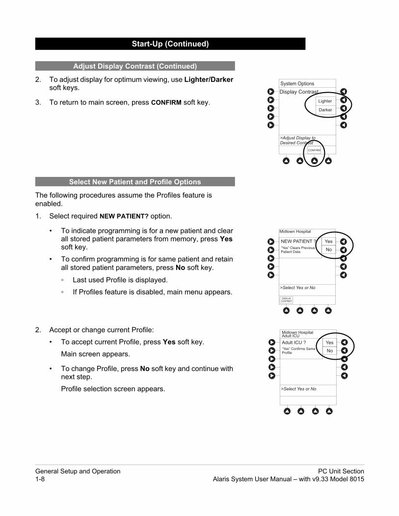
2. To adjust display for optimum viewing, use Lighter/Darker soft keys.
3. To return to main screen, press CONFIRM soft key.
The following procedures assume the Profiles feature is enabled.
1. Select required NEW PATIENT? option.
• To indicate programming is for a new patient and clear all stored patient parameters from memory, press Yes soft key.
• To confirm programming is for same patient and retain all stored patient parameters, press No soft key.
◦ Last used Profile is displayed.
◦ If Profiles feature is disabled, main menu appears.
2. Accept or change current Profile:
• To accept current Profile, press Yes soft key.
Main screen appears.
• To change Profile, press No soft key and continue with next step.
Profile selection screen appears.
Start-Up (Continued)
Adjust Display Contrast (Continued)
Select New Patient and Profile Options
General Setup and Operation PC Unit Section1-8 Alaris System User Manual – with v9.33 Model 8015

Midtown HospitalProfiles
>Press CONFIRM
CONFIRM PAGEDOWN
Neonatal
Peds ICU
Neonatal ICU
Adult General Care
Adult ICU
1 of 2
EXIT
A
B
C
D
PAGEDOWN
>Enter Patient ID and PressCONFIRM
E
K-O
F-J
P-T
U-Y
A-E
Patient ID Entry
_ _ _ _ _ _ _ _ _ _ _ _ _ _ _ _
CONFIRM
3. To select a Profile, press corresponding left soft key.
To view additional choices, press PAGE DOWN soft key.
4. To confirm Profile selection, press CONFIRM soft key.
Main screen appears.
The option to enter and display a 16-character alphanumeric patient identifier is always available. The instrument can be configured to automatically display the Patient ID Entry screen during start-up or to provide access only through the Systems Options menu (see "System Options").
If Yes was selected to indicate programming for a new patient, perform one of following steps:
• If patient identifier is not required, press CONFIRM or EXIT soft key.
• To manually enter patient identifier, use numeric data entry keys and/or alpha speed keys.
◦ An alphanumeric identifier, of up to 16 characters, can be entered.
◦ Press soft key next to a letter group to list letters in that group. Press soft key next to an individual letter to enter that letter.
◦ To access letter "Z" and special characters (hyphen, underscore, space), press PAGE DOWN soft key.
◦ To clear an entire entry, press CLEAR key.
◦ To back up a single character at a time, press CANCEL key.
• To scan barcode on patient identification band, see"Alaris Auto-ID Module Model 8600", section 6 of this User Manual.
Start-Up (Continued)
Select New Patient and Profile Options (Continued)
Patient ID Entry Feature
PC Unit Section General Setup and OperationAlaris System User Manual – with v9.33 Model 8015 1-9

The user should check that the current alarm preset is appropriate prior to use on each patient.
WARNING
A hazard can exist if different Alarm Presets are used for the same or similar equipment in a single area, such as an Intensive Care Unit or a Cardiac Operating Theatre.
WARNING
VTBI = 250.0 mL
VOLUMEINFUSED
AUDIOADJUST
Midtown HospitalAdult ICU
Setting the audio volume to the lowest level will lower all system alarms, including secondary alarms such as End of Infusion.
CAUTION
Louder
>Change Setting or
Cancel
Audio Volume Adjust
Test
Softer
MAINSCREEN
3
1. Press AUDIO ADJUST soft key.
2. To change volume to desired level, press either Louder or Softer soft key. To sample alarm loudness level, press Test soft key.
3. To return to PC unit screen, press MAIN SCREEN soft key.
After 30 seconds without a key press, Main Display appears.
Start-Up (Continued)
Adjust Audio Volume
NOTE:The Minimum Audio Volume defaults to level 1. Levels 1-5 may be set per profile. The user is able to lower the device AUDIO VOLUME to the minimum limit set. When the minimum AUDIO VOLUME LEVEL has been reached, the Louder/Softer soft keys are unavailable and the PC unit emits an illegal key press audio.
General Setup and Operation PC Unit Section1-10 Alaris System User Manual – with v9.33 Model 8015

PANEL LOCKED
VTBI = 250.0 mL
VOLUMEINFUSED
AUDIOADJUST
Midtown HospitalAdult ICU
PANEL UNLOCKED
VTBI = 250.0 mL
VOLUMEINFUSED
AUDIOADJUST
Midtown HospitalAdult ICU
1. Initiate operation of applicable module.
2. Press and hold Tamper Resist Switch, on back of PC unit, for 3 to 4 seconds (see "General Information," "Features and Displays," "Operating Features, Controls, Indicators").
• An advisory tone (if Key Click Audio is enabled) and a three-second PANEL LOCKED prompt on Main Display confirm activation.
• When Tamper Resist is active, keypad panel is locked; however, clinician can:
◦ Silence audio alarm.◦ View volume(s) infused.◦ View and test audio alarm setting.◦ View selected parameters on attached modules.
Any other key press results in a visual PANEL LOCKED prompt and, if Key Click Audio is enabled, an illegal key–press audio advisory.
3. To unlock keypad panel, press and hold Tamper Resist Switch for 3 to 4 seconds.
An advisory tone (if Key Click Audio is enabled) and a three-second PANEL UNLOCKED prompt on Main Display confirm activation.
Start-Up (Continued)
Lock/Unlock Tamper Resist
PC Unit Section General Setup and OperationAlaris System User Manual – with v9.33 Model 8015 1-11

Powering Down
Press and hold CHANNEL OFF key until a beep is heard (approximately 1.5 seconds) and then release to initiate power down.
• During power off sequence, Main Display flashes Powering Down.
• To interrupt power down sequence, quickly press any key (except SYSTEM ON) on PC unit.
Once all attached modules are powered off, PC unit automatically powers down.
Power Off System
General Setup and Operation PC Unit Section1-12 Alaris System User Manual – with v9.33 Model 8015

SILENCE
OPTIONS
147
CLEAR
2580
369 ENTER
CANCEL
SYSTEMON
>Select an Option orEXIT
PAGEDOWNEXIT
Display Contrast
Clinician ID
Power Down All Channels
Anesthesia Mode
Patient ID
System Options 1 of 3
>Select an Option orEXIT
PAGEDOWNEXIT
Display Contrast
Clinician ID
Power Down All Channels
Anesthesia Mode
Patient ID
System Options 1 of 3
1. Press OPTIONS key.
2. Press Display Contrast soft key.
3. Adjust display and return to main screen (see Start-Up," Adjust Display Contrast" procedure).
1. Press OPTIONS key.
2. Press Patient ID soft key.
System Options
Display Contrast
Patient ID
Enter
PC Unit Section General Setup and OperationAlaris System User Manual – with v9.33 Model 8015 1-13

EXIT
A
B
C
D
PAGEDOWN
>Enter Patient ID and PressCONFIRM
E
K-O
F-J
P-T
U-Y
A-E
Patient ID Entry
123456789CD_ _ _ _ _
CONFIRM
3. Scan or manually enter patient identifier:
• To manually enter patient identifier, use numeric data entry keys and/or alpha speed keys.
◦ An alphanumeric identifier, of up to 16 characters, can be entered.
◦ Press soft key next to a letter group to list letters in that group. Press soft key next to an individual letter to enter that letter.
◦ To access letter "Z" and special characters (hyphen, underscore, space), press PAGE DOWN soft key.
◦ To clear an entire entry, press CLEAR key.
◦ To back up a single character at a time, press CANCEL key.
• To scan barcode on patient identification band, see AUTO-ID section of this User Manual.
4. To verify correct entry, press CONFIRM soft key.
System Options (Continued)
Patient ID (Continued)
Enter (Continued)
General Setup and Operation PC Unit Section1-14 Alaris System User Manual – with v9.33 Model 8015
SILENCE
OPTIONS
147
CLEAR
2580
369 ENTER
CANCEL
SYSTEMON
OR
EXIT
A
B
C
D
PAGEDOWN
>Enter Patient ID and PressCONFIRM
E
K-O
F-J
P-T
U-Y
A-E
Patient ID Entry
234567891EF_ _ _ _ _
CONFIRM
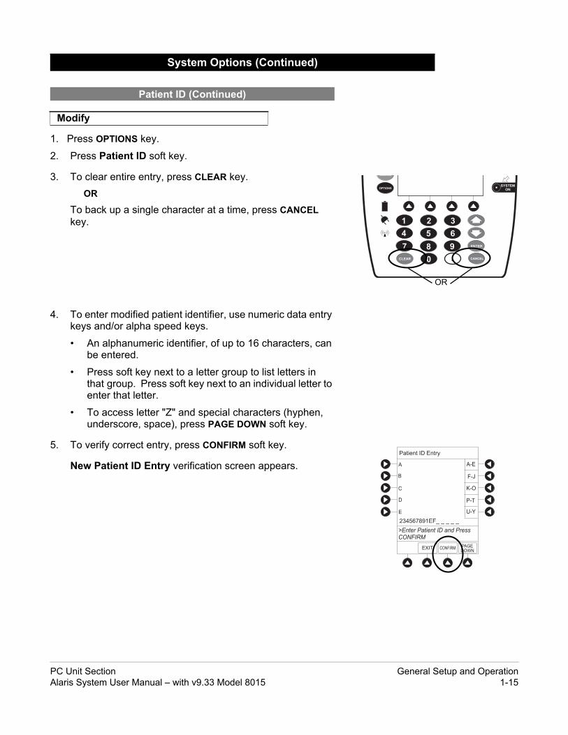
1. Press OPTIONS key.
2. Press Patient ID soft key.
3. To clear entire entry, press CLEAR key.OR
To back up a single character at a time, press CANCEL key.
4. To enter modified patient identifier, use numeric data entry keys and/or alpha speed keys.
• An alphanumeric identifier, of up to 16 characters, can be entered.
• Press soft key next to a letter group to list letters in that group. Press soft key next to an individual letter to enter that letter.
• To access letter "Z" and special characters (hyphen, underscore, space), press PAGE DOWN soft key.
5. To verify correct entry, press CONFIRM soft key.
New Patient ID Entry verification screen appears.
System Options (Continued)
Patient ID (Continued)
Modify
PC Unit Section General Setup and OperationAlaris System User Manual – with v9.33 Model 8015 1-15

>Press Yes or No
Patient ID Entry
Yes
No
Patient ID
123456789CD
will be changed to
234567891EF
Is this correct?
>Select an Option orEXIT
PAGEDOWNEXIT
Display Contrast
Clinician ID
Power Down All Channels
Anesthesia Mode
Patient ID
System Options 1 of 3
6. To accept modified Patient ID, press Yes soft key.
Main screen appears with new Patient ID.
OR
To retain original (old) Patient ID, press No soft key.
Main screen appears with old Patient ID.
1. Press OPTIONS key.
2. Press Clinician ID soft key.
3. Scan or manually enter clinician identifier:
To manually enter clinician identifier, use numeric data entry keys and/or alpha speed keys.
• An alphanumeric identifier, of up to 16 characters, can be entered.
• Press soft key next to a letter group to list letters in that group. Press soft key next to an individual letter to enter that letter.
• To access letter "Z" and special characters (hyphen, underscore, space), press PAGE DOWN soft key.
• To clear an entire entry, press CLEAR key.
• To back up a single character at a time, press CANCEL key.
System Options (Continued)
Patient ID (Continued)
Modify (Continued)
Clinician ID
General Setup and Operation PC Unit Section1-16 Alaris System User Manual – with v9.33 Model 8015

EXIT
A
B
C
D
PAGEDOWN
>Enter Clinician ID and PressCONFIRM
E
K-O
F-J
P-T
U-Y
A-E
Clinician ID Entry
123456789CD_ _ _ _ _
CONFIRM
>Select an Option orEXIT
PAGEDOWNEXIT
Display Contrast
Clinician ID
Power Down All Channels
Anesthesia Mode
Patient ID
System Options 1 of 3
System Options
Yes
No
Power DownAll Channels?
>Press Yes or No
4. To verify correct entry, press CONFIRM soft key.
1. Press OPTIONS key.
2. Press Power Down All Channels soft key.
3. Press Yes soft key.
During power off sequence, Main Display flashes POWERING DOWN.
System Options (Continued)
Clinician ID (Continued)
Power Down All Channels
PC Unit Section General Setup and OperationAlaris System User Manual – with v9.33 Model 8015 1-17

When the Alaris System is set up for use in Anesthesia Mode, it is important to select the Profile that corresponds with the care area the patient will be taken to when the Anesthesia Mode is discontinued. This ensures that the Alaris System will be in the correct Profile following the use of the Anesthesia Mode.
WARNING
>Select an Option orEXIT
PAGEDOWNEXIT
Display Contrast
Clinician ID
Power Down All Channels
Anesthesia Mode
Patient ID
System Options 1 of 3
When the Anesthesia Mode is enabled and then the pause feature is used - the module remains in an indefinite pause until restarted.
When Anesthesia Mode is enabled:
• A channel can be paused indefinitely without an alarm.
• The air-in-line associated with the Profile can be set up to 500 micro liters.
• All limits are set to Soft.• Limit Checking mode is set to Smart.• Key-press audio is turned off.
• Auto-Restart for Anesthesia Mode is set to 9 and is not configurable.
• Panel Lock through Tamper Resist Mode or Authorized User Mode is not available.
• Guardrails drug list defaults to drugs designated by Editor Software as anesthesia only. All Guardrails drugs in a Profile can be viewed by pressing ALL DRUGS soft key.
• Bolus Dose is automatically available for:
◦ Guardrails drugs that have Bolus Dose limits defined
◦ generic drug calculation setup
• Anesthesia Mode, alternating with other required prompts, is displayed in prompt bar of Main Display.
• Callback audio for paused module is permanently silenced.
• Review of drug calculation setup page is omitted when restoring a stopped drug calculation.
• Clinical Advisories are not displayed.
1. Press OPTIONS key.
System Options (Continued)
Anesthesia Mode
Enable
NOTE:If an infusion is paused in regular mode and then the anesthesia mode is enabled - the device will alarm at the 2 minute warning.
General Setup and Operation PC Unit Section1-18 Alaris System User Manual – with v9.33 Model 8015

System Options
>Select an Option or PressCONFIRM
Anesthesia Mode
Pump ModuleAir Detection =75 microliters
Enable
Change
CONFIRM
Disable
2. Press Anesthesia Mode soft key.
3. Press Enable soft key.
4. Press CONFIRM soft key.
The Anesthesia Mode can be disabled, and normal operation resumed, using either of the following three methods:
• System Options menu.• Disconnecting from AC power.• Connecting to AC power.
From System Options Menu
1. Press OPTIONS key.
2. Press Anesthesia Mode soft key.
3. Press Disable soft key.
4. Press CONFIRM soft key.
Anesthesia Mode no longer appears on Main Display, indicating it has been disabled.
System Options (Continued)
Anesthesia Mode (Continued)
Enable (Continued)
Disable
PC Unit Section General Setup and OperationAlaris System User Manual – with v9.33 Model 8015 1-19

AC power cord wasconnected.Continue
?ANESTHESIA MODE
Yes
No
>Select Yes or No
CONFIRM
Anesthesia mode waswhen AC powerdisconnected.continue normal operation.
discontinuedcord was
Press CONFIRM to
>Press CONFIRM
Connect to AC Power
1. Connect system to AC power.
2. To continue using Anesthesia Mode, press Yes soft key.OR
To discontinue Anesthesia Mode, press No soft key.
Disconnect from AC Power
1. Disconnect system from AC.
• Anesthesia Mode is automatically disabled.
• All currently running infusions continue.
• A prompt appears as an alert that Anesthesia Mode has been discontinued.
2. Press CONFIRM soft key.
System Options (Continued)
Anesthesia Mode (Continued)
Disable (Continued)
General Setup and Operation PC Unit Section1-20 Alaris System User Manual – with v9.33 Model 8015

System Configurations
>Select an Option orEXIT
EXIT
Software Versions
Serial Numbers
Battery Runtime
PAGEDOWN
Time of Day
PAGE UP
System Options 2 of 3
System Options
>Press CANCEL or EXIT
EXIT
9.5 hours
Estimated batteryruntime at currentoperating parameters
System Configurations
>Select an Option orEXIT
EXIT
Software Versions
Serial Numbers
Battery Runtime
PAGEDOWN
Time of Day
PAGE UP
System Options 2 of 3
1. Press OPTIONS key.
2. Press PAGE DOWN soft key.
3. Press Battery Runtime soft key.
4. To return to main screen, press CANCEL key or EXIT soft key.
1. Press OPTIONS key.
2. Press PAGE DOWN soft key.
3. Press System Configuration soft key.
System Options (Continued)
Battery Runtime
System Configurations
PC Unit Section General Setup and OperationAlaris System User Manual – with v9.33 Model 8015 1-21

Factory Default: Yes
System Configuration - Module
PC Unit
Pump Module
SPO2 Module
>Press CANCEL or EXIT
EXIT
Shared Infusion Settings
PAGEDOWN
EXITPAGEUP
System Config - PCU 2 of 3
500 kgMax Pt. weight:
Patient ID Entry: Disabled
>Press CANCEL or EXIT
PAGEDOWN
Key click audio: Enabled
2 m2Max Pt. BSA:
>Press CANCEL or EXIT
PAGEDOWNEXIT
System Config - PCU 1 of 3
Alarm audio: Profile 1
Battery meter: Disabled
Clock setup: 09:00
Anesthesia Mode: Disabled
Limit Checking: ALWAYS
4. Press PC Unit soft key.
5. To review various system configuration settings, press PAGE DOWN and PAGE UP soft keys.
System Options (Continued)
General Setup and Operation PC Unit Section1-22 Alaris System User Manual – with v9.33 Model 8015

EXITPAGE
UP
System Config - PCU 3 of 3
PM Reminder: Disabled
>Press CANCEL or EXIT
Tamper resist: Disabled
System Configurations
>Select an Option orEXIT
EXIT
Software Versions
Serial Numbers
Battery Runtime
PAGEDOWN
Time of Day
PAGE UP
System Options 2 of 3
6. To return to main screen, press CANCEL key or EXIT soft key.
1. Press OPTIONS key.
2. Press PAGE DOWN soft key.
3. Press Serial Numbers soft key.
Serial numbers for PC unit and all attached modules display.
System Options (Continued)
System Configurations (Continued)
Serial Numbers
NOTE: The Profiles option is listed only if it is disabled. The Limit Checking and Max Pt. BSA options are listed only if
the Profiles option is enabled and a valid Data Set is loaded.
PC Unit Section General Setup and OperationAlaris System User Manual – with v9.33 Model 8015 1-23

Serial Number Review
PC Unit: nnnn-nnnnnnnn
nnnn-nnnnnnnn
nnnn-nnnnnnnn
nnnn-nnnnnnnn
nnnn-nnnnnnnn
Module A:
Module B:
Module C:
Module D:
>Press CANCEL or EXIT
EXIT
System Configurations
>Select an Option orEXIT
EXIT
Software Versions
Serial Numbers
Battery Runtime
PAGEDOWN
Time of Day
PAGE UP
System Options 2 of 3
Software Rev. Review
PC Unit:
Module A:
Module B:
Module C:
Module D:
View
View
View
View
View
>Select an Option orEXIT
EXIT
OR
4. To return to main screen, press EXIT soft key.
1. Press OPTIONS key.
2. Press PAGE DOWN soft key.
3. Press Software Versions soft key.
4. To review software version information, press View soft key next to applicable module.
OR
To return to main screen, press EXIT soft key.
System Options (Continued)
Serial Numbers (Continued)
Software Versions
NOTE: "nnnn-nnnnnnnn" in the illustrated display represents a model
and serial number.
General Setup and Operation PC Unit Section1-24 Alaris System User Manual – with v9.33 Model 8015

EXIT
>Press CANCEL or EXIT
Software Rev. Review
Module Software: A
Main processor: nn.nn
nn.nn
nn.nn
Main boot block:
Keyboard:
System Configurations
>Select an Option orEXIT
EXIT
Software Versions
Serial Numbers
Battery Runtime
PAGEDOWN
Time of Day
PAGE UP
System Options 2 of 3
Time of Day
System Options
Current time:
09:00
ChangeTime
CONFIRM
>CONFIRM Time-of-Day
EXIT
5. To return to previous screen, press EXIT soft key.
1. Press OPTIONS key.
2. Press PAGE DOWN soft key.
3. Press Time of Day soft key.
4. If time is correct, press CONFIRM soft key.
OR
To change time, press Change Time soft key.
System Options (Continued)
Software Versions (Continued)
Time of Day
NOTE: "nn.nn" in the illustrated display represents a software
version.
PC Unit Section General Setup and OperationAlaris System User Manual – with v9.33 Model 8015 1-25

Time of Day
System Options
Current time:
__:__
Change
Time
CONFIRM
>Enter Current Time
EXIT
Time of Day
System Options
Current time:
14:30Change
Time
CONFIRM
>Press CONFIRM
EXIT
5. Enter current Time of Day.
6. Press CONFIRM soft key.
The displayed status updates immediately when a status change takes place.
1. Press OPTIONS key.
2. Press PAGE DOWN soft key two times.
System Options (Continued)
Time of Day (Continued)
Network Status
NOTE: The format is a 24-hour clock (military time).
General Setup and Operation PC Unit Section1-26 Alaris System User Manual – with v9.33 Model 8015

System Options 3 of 3
>Select an Option orEXIT
EXIT
Network Status
Maintenance Due Yes
Wireless Connection
Data Set Status
PAGE UP
Viewing Network Statusis only to be used byqualified personnel.
* _ _ _ _
System Options
EXIT CONFIRM
>Enter Password orEXIT
>Press CANCEL to Exit
Wireless StatusStatus :
Channel :
Authentication :
ASSOCIATED
1 (2.412 Ghz)OPEN
40 bit WEP
SSID :
BSSID :
AM SWEPXXXXXXXXXXXXXXXXXXXXXXX
00:0A:B3:36:9F:88
Encryption:
NETSTATUS
NETADDRESS
SERVERSTATUS
Link Quality
Signal Strength75%35%
System Options
Speed: 11 Mbps
3. To view network status and wireless status information, press Network Status soft key.
4. Enter password (refer to v9.5 or later System Maintenance software instructions) and press CONFIRM soft key.
• Information based on a wireless status of DISABLED, DISASSOCIATED, CONFIGURING, ASSOCIATING, ASSOCIATED, or AUTHENTICATING is displayed.
• If wireless status is ASSOCIATED, following information is displayed:
◦ Wireless connectivity: SSID, Channel, Authentication, and Encryption types being used; BSSID—MAC address of access point that system is connected to; Speed—transfer rate up to 11 Mbps for 802.11b, 54 Mbps for 802.11a or 802.11b/g and 72 Mbps for 802.11a/b/g/n.
◦ Link Quality—a minimum of 20% recommended for good wireless connectivity.
◦ Signal Strength—greater than 20% recommended for good wireless connectivity.
5. To view network connectivity information, press NET STATUS soft key.
• A status of DISABLED, DISCONNECTED, CONFIGURING, INVALID CONFIG, or CONNECTED is displayed.
• If status is CONNECTED:
◦ PC unit is connected to wireless network.
◦ Profile being used is displayed.
System Options (Continued)
Network Status (Continued)
PC Unit Section General Setup and OperationAlaris System User Manual – with v9.33 Model 8015 1-27

>Press CANCEL to Exit
Network StatusStatus : CONNECTED
WIRELESSSTATUS
NETADDRESS
SERVERSTATUS
System Options
Uptime : 03:45:35
1,200,150
13, 890Bytes Sent:
Bytes Recv:
Pre-v9.5 PC unit:
>Press CANCEL to Exit
Network Status
Status:
Profile:
Uptime:
CONNECTED
Site 1
03:45:35
1,200,150
13, 890Bytes Sent:
Bytes Received:
System Options
WIRELESSSTATUS
NETADDRESS
SERVERSTATUS
v9.5 and later PC unit:
>Press CANCEL to Exit
Network Address
WIRELESSSTATUS
SERVERSTATUS
System Options
NETSTATUS
DHCP: Yes
192.168.0.55
MAC Address: 00:0A:B3:36:9F:88
192.168.0.1
255.255.255.0Subnet Mask:
IP Address:
Gateway:
192.168.0.1
192.168.0.3
DNS Primary:
DNS Secondary:
6. To view network address information, press NET ADDRESS soft key.
• MAC Address of wireless RF card attached to PC unit is displayed.
• If DHCP displays NO, PC unit is set to use a Static IP address.
• When PC unit is connected to wireless network, IP Address, Subnet Mask, Gateway, and DNS information is displayed.
7. To view server connectivity information, press SERVER STATUS soft key.
System Options (Continued)
Network Status (Continued)
General Setup and Operation PC Unit Section1-28 Alaris System User Manual – with v9.33 Model 8015

Server StatusStatus: CONNECTED
System Options
WIRELESSSTATUS
NETSTATUS
NETADDRESS
>Press CANCEL to Exit
TCP Port:
Uptime:
3613
00:00:02192.168.0.2AlarisServer1.JDhospit
20ms20ms
UNKNOWN
AES 128-bit1,103,470,77694,300
Server Address:Server Name:
Local Timeout:
Server Timeout:
Bytes Sent:Bytes Received:
Last Disconnect:
Encryption:
v9.5 and later PC unit:
System Options 3 of 3
>Select an Option orEXIT
EXIT
Network Status
Maintenance Due Yes
Wireless Connection
Data Set Status
PAGE UP
• Information based on a status of DISABLED, DISCONNECTED, CONNECTING, or CONNECTED is displayed.
• If status is CONNECTED, PC unit is connected to Alaris Systems Manager and the following information is displayed:
◦ Uptime—length of time PC unit has been connected.
◦ Server Address—IP Address of Alaris Systems Manager.
◦ TCP Port being used to establish connection.
◦ Encryption type (AES 128-bit) used to encode data on payload and protect patient-sensitive information sent through wireless network.
◦ Bytes Sent—cumulative total of data sent.
◦ Bytes Received—cumulative total of data received.
◦ Server Name first 20 characters of fully qualified domain name of Alaris Systems Manager.
1. Press OPTIONS key.
2. Press PAGE DOWN soft key two times.
3. Press Wireless Connection soft key.
If Wireless Connection soft key is inactive (grayed out), the PC unit has the following configuration:
• the System Maintenance software was used to disable wireless connection
• the CF card flashing process was done without the programming of the proper AppConfig file (v9.12 or later) For more information, refer to the Alaris PC Unit Model 8015 Software and Hardware Upgrade Instructions to v9.33.
• A valid network configuration was never transferred
To enable wireless connection, use v9.5 or later System Maintenance software. Send the PC unit to Biomed to resolve wireless connectivity issues.
System Options (Continued)
Network Status (Continued)
Wireless Connection
PC Unit Section General Setup and OperationAlaris System User Manual – with v9.33 Model 8015 1-29

System Options
WirelessConnection Disable
Enable
>Press ENABLE orDISABLE
System Options 3 of 3
>Select an Option orEXIT
EXIT
Network Status
Maintenance Due Yes
Wireless Connection
Data Set Status
PAGE UP
4. Wireless connection can be disabled or enabled:
• To disable wireless communication, press Disable soft key.
◦ If wireless connection is disabled, it remains disabled until PC unit is powered off. Setting defaults to Enable when PC unit is powered back on.
◦ v10.33 or later System Maintenance software instructions also includes a procedure on how to disable a wireless RF card on a PC unit being used in a non-wireless environment. Wireless connection remains disabled until System Maintenance software is used to enable it.
• To enable wireless connection, press Enable soft key.
Pre-v9.5 PC unit: View Network Status after pressing Enable soft key. If a Status of DISABLED is identified, System Maintenance software was used to disable wireless connection. Use v9.5 or later System Maintenance software to enable wireless connection.
1. Press OPTIONS key.
2. Press PAGE DOWN soft key two times.
3. To view Data Set status, press Data Set Status soft key.
System Options (Continued)
Wireless Connection (Continued)
Data Set Status
General Setup and Operation PC Unit Section1-30 Alaris System User Manual – with v9.33 Model 8015

B
EXIT
Current:
Pending:
(none available)
Midtown HospitalDataset ID: 83442BBNot Activated
ID: 83442BBActivated: 2005-09-18 08:45ID: 83442BBActivated: 2005-09-18 08:45
System Options
>Press EXIT
Data Set Status
System Options 3 of 3
>Select an Option orEXIT
EXIT
Network Status
Maintenance Due Yes
Wireless Connection
Data Set Status
PAGE UP
BModule(s) due for routinepreventative maintenance:.
>Press CANCEL or EXIT
EXIT
Maintenance Due Dates
Bar Code:
Bar Code:(Hand held)
YYYY-MM-DD
YYYY-MM-DD
System Options
PAGE UP
A status of Current, Pending, Transferring, or Not Activated is displayed.
1. Press OPTIONS key.
2. Press PAGE DOWN soft key two times.
3. Press Maintenance Due soft key.
4. To return to main screen, press EXIT soft key.
System Options (Continued)
Data Set Status (Continued)
Maintenance Due
BModule(s) due for routinepreventative maintenance:.
>Press CANCEL or EXIT
EXIT
Maintenance Due Dates
PC Unit:
Module A:
Module B:
Module C:
Module D:
YYYY-MM-DD
YYYY-MM-DD
YYYY-MM-DD
YYYY-MM-DD
YYYY-MM-DD
System Options
PAGEDOWN
PC Unit Section General Setup and OperationAlaris System User Manual – with v9.33 Model 8015 1-31

System Options (Continued)
Maintenance Due (Continued)
NOTE: PAGE DOWN soft key appears only if an Auto-ID module is
attached.
General Setup and Operation PC Unit Section1-32 Alaris System User Manual – with v9.33 Model 8015

General Information
• Explosion risk if used in the presence of flammable anesthetic agents or gasses.
• Assess patient’s condition before silencing an alarm. Do not silence alarm if patient safety might be compromised.
• Before each use, verify that the alarm limits are appropriate for the patient.
• The Alaris System performs a self check during power up. The PC unit should beep, no errors should occur, and if a module is connected, all LED segments should flash. If the Alaris System fails the self check, remove the failing PC unit or module from use.
• When properly secured/snapped, the release latch provides a very secure connection between modules. If not properly latched, a module can be dislodged during operation.
• Disconnect from main (AC) and battery power when performing maintenance.
• Use only CareFusion batteries. The use of third party batteries could affect the safety and efficacy of Alaris products.
• The battery cannot be repaired and should not be opened.
• The battery is intended as a backup system. Leave the power cord connected to a hospital grade AC power source whenever available.
• Battery replacement should be performed by qualified service personnel while the instrument is not in use.
Warnings and Cautions
General
WARNINGS
PC Unit Section General InformationAlaris System User Manual – with v9.33 Model 8015 1-33

• Electrical shock hazard. Do not open case. Refer to qualified service personnel.
• Due to the intermittent nature of a wireless environment, some data can be lost if a connection cannot be established or is lost. The Alaris Systems Manager and wireless network card are designed to minimize these incidents but cannot eliminate them.
• The Alaris System is not intended to replace supervision by medical personnel. The user must become thoroughly familiar with the Alaris System features, operation, and accessories prior to use.
Warnings and Cautions (Continued)
General (Continued)
WARNINGS
General Information PC Unit Section1-34 Alaris System User Manual – with v9.33 Model 8015

• Always use a grounded three-wire receptacle. Where the integrity of the protective earth grounding system is in doubt, operate on internal battery.
• Hyperbaric Chamber Operation:◦ The Alaris System is not certified for use in oxygen-
enriched environments.
◦ The Alaris System, with the exclusion of the EtCO2 module, has been verified to operate with no malfunction alarms due to the hyperbaric chamber environment or unintentional key presses when used in a hyperbaric chamber.
◦ The healthcare facility's hyperbaric safety director is responsible for all equipment used in the hyperbaric chamber environment.
• Should an instrument or accessory be dropped or severely jarred, it should be immediately taken out of use and inspected by qualified service personnel to ensure its proper function prior to reuse.
• If an instrument appears damaged, contact CareFusion for authorization to return it for repair.
Warnings and Cautions (Continued)
General (Continued)
CAUTIONS
PC Unit Section General InformationAlaris System User Manual – with v9.33 Model 8015 1-35

• Do not use the Alaris System near Magnetic Resonance Imaging (MRI), including Stereotaxis technology.
• Do not use the Alaris System near Therapeutic Radiation equipment, such as Linear Accelerators.
• Use of any accessory, transducer or cable other than those specified can result in increased emissions or decreased Alaris System immunity.
• Do not use an RF device within 7.8 inches/20 cm of the Radio Card on the PC unit. FCC approval of the Radio Card excludes co-location with any other transmitter.
• Per FCC regulations, maintain a distance of at least 7.8 inches/20 cm between the Radio Card on the PC unit and a human body.
Warnings and Cautions (Continued)
Electromagnetic Compatibility
WARNINGS
General Information PC Unit Section1-36 Alaris System User Manual – with v9.33 Model 8015

to the attached module(s) for features
ition
er clinician identifier that can be
ing tool and then transferred to est-practice guidelines for IV Drug rug Libraries, Clinical Advisories, el Label Libraries.
• The Alaris System should not be used adjacent to or stacked with other equipment. If adjacent or stacked use is necessary, monitor the Alaris System to verify that it is operating normally in that setup.
• Portable and mobile RF communications can affect medical electrical equipment.
• Interconnected data communications systems must be certified to IEC 60950 (data processing equipment) or IEC 60601–1 (electromedical equipment).
• The Alaris System is intended for use by healthcare professionals only. This is a CISPR 11 Class B Group 1 medical system. In a domestic environment, this system can cause radio interference. Reorienting, relocating or shielding the system, or filtering the connection to the public mains network, are examples of steps that can be taken to reduce or eliminate interference.
• Medical electrical equipment needs special precautions regarding EMC and needs to be installed and used according to the EMC information provided in the "Appendix" section of this User Manual (see "Regulations and Standards," "Compliance").
Warnings and Cautions (Continued)
Electromagnetic Compatibility (Continued)
Features and Displays
Features and Definitions
See the product-specific section of this User Manual that applies and definitions specific to that module.
Feature Defin
Clinician ID An optional alphanumeric 16-charactentered and displayed.
Data Set Created using Editor Software authorPC unit. A Data Set reflects facility’s badministration and includes: Profile Dinstrument configurations, and Chann
CAUTIONS
PC Unit Section General InformationAlaris System User Manual – with v9.33 Model 8015 1-37

ition
g errors by:ettings to meet need of selected
hospital-defined best-practice
pt if an out-of-limits entry is made.
r patient identifier that can be
Startup screen.cessible from System Options
settings and best-practice guidelines tient type, and can consist of
g names, standard concentrations, ptional associated Clinical Advisories e infusion.
ary consisting of IV Fluids (for ate of delivery.(alphanumeric) labels, which allows be used to indicate route of delivery
facility’s own multi-disciplinary team le parameters are used to create a the PC unit.
ed. If Profiles feature is enabled, the rofile are automatically activated.
f the front panel keypad when the a SpO2 or EtCO2 module is actively nt panel keypad during KVO. An e panel is locked.
Features and Displays (Continued)
Features and Definitions (Continued)
Feature Defin
Guardrails Suite MX Designed to help prevent programmin• Customizing device configurable s
hospital/facility area/unit (Profile).• Comparing user-programming with
guidelines.• Providing a visual and audio prom
Patient ID An optional alphanumeric 16-characteentered and displayed• When enabled, ID entry defaults to• When disabled, ID entry is only ac
screen.
Profile A unique set of system configuration for a specific patient population or pafollowing components:• Instrument configuration settings.• A Drug Library, which includes dru
dosing units, duration limits, and ofor both continuous and Bolus Dos
• An IV Fluid library, an optional librexample, TPN) and limits around r
• A Channel Label Library with text identification (on modules) that can(for example, epidural).
Profile settings are established by theprior to system implementation. ProfiData Set, which is then transferred to
System Configuration Allows system settings to be customizsystem settings defined for selected P
Tamper Resist Provides a quick one-touch lockout oinfusion is running, during a delay, ormonitoring. You cannot lockout the froalarm can be silenced even though th
General Information PC Unit Section1-38 Alaris System User Manual – with v9.33 Model 8015

IUI Connector, Right
Cancel Key: When pressed, sequentially backs out of current setup sequence.
Decimal Key: When pressed, inserts a decimal point in numeric data.
Numeric Keypad
System On Key: Whenpressed, changes Alaris Systemfrom standby to operating mode.
Up Key: When pressed,increases parameter with eachkey press or scrolls up when pressed and held.
Down Key: When pressed,decreased parameter with eachkey press or scrolls down when pressed and held.
Enter Key: When pressed,confirms current parameter entry.
Features and Displays (Continued)
Operating Features, Controls, Indicators
IUI Connector, Left(not visible)
Options Key: When pressed, allows access to available System or Channel Options.
Silence Key: When pressed during an alarm, silences audio for 2 minutes.
Soft Keys: When pressed, allows selection of options or infusion parameters appearing on Main Display adjacent to soft key.
Main Display
Power Indicator: When illuminated, indicates Alaris System is connected to an AC power source.
Wireless Network Indicator: When illuminated, indicates Alaris System is connected to Alaris Systems Manager. When blinking, indicates data transfer.
Module Release Latch: When pressed, allows module to be removed.
Soft Keys (see above)
Battery Indicator: When illuminated, indicates Alaris System is operating on battery power.
Clear Key: When pressed, clears current selected parameter setting to "0".
PC Unit Section General InformationAlaris System User Manual – with v9.33 Model 8015 1-39

Power Cord Strap
IUI Connector, Left
Wireless Antenna/Network
Card
Rear Cover
Features and Displays (Continued)
Operating Features, Controls, Indicators (Continued)
Rear Panel - IEC 802.11 a/b/g/n Wireless Network Card
Use this bolt to reorient Pole Clamp 90° for attachment to a bed rail instead of a pole.
Tamper Resist Switch
IUI Connector, Right
Connector Plug over RJ45 Communication Data Port.
Primary Audio Speaker
General Information PC Unit Section1-40 Alaris System User Manual – with v9.33 Model 8015

Power Cord Strap
IUI Connector, Left
Compact Flash Wireless Network Card (see illustration below for
LED location)
less Network Card LED
Flashes green when is System is powered up.
Features and Displays (Continued)
Operating Features, Controls, Indicators (Continued)
Rear Panel - Compact Flash b/g or a/b/g Wireless Card
Use this bolt to reorient Pole Clamp 90° for attachment to a bed rail instead of a pole.
Tamper Resist Switch
IUI Connector, Right
Connector Plug over RJ45 Communication Data Port.
Primary Audio Speaker
Wire
Alar
PC Unit Section General InformationAlaris System User Manual – with v9.33 Model 8015 1-41

The displays illustrated throughout this document are for illustration purposes only. The display content varies, depending on configuration settings, hospital-defined Data Set uploaded using the Guardrails Suite MX, and many other variables.
A color versus monochrome display option is available when creating a hospital-defined, best-practice Data Set. If no Data Set is present or the Profiles feature is disabled, the default is a color display. During normal operation, the title and prompt bars are blue when a color display is enabled. See "Troubleshooting and Maintenance," "Alarms, Errors, Messages" for additional color categories.
Features and Displays (Continued)
Displays
Main Display
VTBI = 250.0 mL
VOLUMEINFUSED
AUDIOADJUST
Midtown HospitalAdult ICU
>Press START
Infusion Setup
RATE 40 mL/h
_250 mL
PAUSESECOND-
ARYSTART
VTBI
Module Selected Indicator"Inactive" Soft Key
Non-highlighted indicates a non-selected soft key.
"Active" Soft KeyHighlighted indicates a selected soft key.
Prompt BarLook here for user prompts.
Title Bar
Module Status• A solid letter display indicates
module is operating.• An outlined letter display
indicates module is attached and ready for use.
Soft Keys
General Information PC Unit Section1-42 Alaris System User Manual – with v9.33 Model 8015

or 4
bled
bled
me
bled
bled
bled
bled
bled
If the configuration settings need to be changed from the Factory default settings, refer to the applicable Technical Service Manual or contact CareFusion Technical Support, for technical, troubleshooting, and preventive maintenance information.
With the Profiles feature enabled, the settings are configured independently for each Profile. A hospital-defined, best- practice Data Set must be uploaded to enable the Profiles feature. Date and Time is a system setting and is the same in all Profiles.
System Configurable Settings
Feature Default Setting Options
Alarm Audio Profile 1 Profile 1, 2, 3,
Anesthesia Mode Disabled Enabled - Disa
Battery Meter Disabled Enabled - Disa
Clock Setup (Date and Time) Not Applicable Set date and ti
Key Click Audio Enabled Enabled - Disa
Max Patient Weight 500 kg 0.1 - 500 kg
Patient ID Entry Disabled Enabled - Disa
PM Reminder(Preventive Maintenance)
Enabled Enabled - Disa
Profiles Disabled Enabled - Disa
Tamper Resist Disabled Enabled - Disa
PC Unit Section General InformationAlaris System User Manual – with v9.33 Model 8015 1-43

ber of modules attached and module y, the system operates as follows before occurs:sion at 999 mL/h and one Auto-ID modulesing at 25 mL/hsing at 25 mL/h and one Auto-ID moduleusing at 25 mL/husing at 25 mL/h and one Auto-ID moduleule PCA module infusing at 5 mL/hor one PCA module and three Syringe
le
lamp)
ored in compact flash memory along with
torical reporting logs, and the system rd flash memory in the Alaris PC unit and d can be held indefinitely or until replaced are maintained even during a total loss of of system power down is captured in the
ged as the log file reaches capacity. The uthorized User Modes restricts access to e of logs.for 8 hours when system is turned , or if a module is detached, module- odule-specific operating parameters are r EtCO2 module is detached and replaced ule, its module-specific trend data is
ischarged battery as data is stored on
tion software, audio wave files, Data Set, ata for operating system software, all rate the Alaris System.are needed to initially turn on Alaris s boot software application, and events,
ttery logs.
Specifications and Symbols
Specifications
Battery Operation: Battery run time is a function of the numactivity. With a new, fully charged battera "BATTERY DISCHARGED" message• 1 hour with four Pump modules infu• 6 hours with one Pump module infu• 6 hours with one Pump module infu• 3 hours with four Pump modules inf• 3 hours with four Pump modules inf• 4.5 hours with one active SpO2 mod• 6 hours with one Syringe module or• 3 hours with four Syringe modules,
modules, infusing at 5 mL/h• 4 hours with one active EtCO2 modu
Communication Data Port: RS-232 with an RJ45 connector.
Dimensions: 6.9" W x 8.8" H x 9" D (including pole c
Electric Classification: Class 1, Internally Powered Equipment
Electronic Memory: The System configuration/data set is stoperating software. The events and error logs, CQI, and hisalarm settings are stored in the on-boamodules. This is nonvolatile memory anwith new data. Logs and alarm settingspower to the system. The date and timeevent log. The older log entries are purAlaris System's Tamper Resist Mode/Amaking changes to logs or to the storagModule-specific parameters are stored off. After 8 hours of continuous off-timespecific trend data (if applicable) and mautomatically purged. If a PCA, SpO2 owith another PCA, SpO2, or EtCO2 modpurged.Memory will not be lost due to a weak/dflash memory as noted.Compact flash memory: Stores applica
and hex files dneeded to ope
On-board flash memory: Contains softwSystem. Storeerrors and ba
General Information PC Unit Section1-44 Alaris System User Manual – with v9.33 Model 8015

)
tem must remain in an upright position.
lied part
perating Storage/Transport
- 4560 mmHg - 6080 hPa)
375 - 760 mmHg(500 - 1013 hPa)
20 - 90%ncondensing
5 - 85%Noncondensing
1 - 104°F(5 - 40°C)
-4 - 140°F(-20 - 60°C)
Specifications and Symbols (Continued
Specifications (Continued)
Environmental Conditions:
Equipment Orientation: To ensure proper operation, Alaris Sys
Fluid Ingress Protection: IPX1, Drip Proof
Mode of Operation: Continuous
Power Requirements: 100 - 240V ~, 50/60 Hz, 150 VA MAX
Shock Protection: Type CF, Defibrillator-Proof patient app
Weight: 7.2 lbs
Symbol Meaning O
Atmospheric Pressure
525 (700
Relative Humidity(Avoid prolonged exposure to relative humidity >85%)
No
Temperature Range
4
PC Unit Section General InformationAlaris System User Manual – with v9.33 Model 8015 1-45

)
to the attached module(s) for symbols
ached to alternating current source,
mentation.
aring this mark have been tested d Canadian electrical safety and
t.
ype and rating.
to establish power and dules.
dicates month and year of
Specifications and Symbols (Continued
Symbols
See the product-specific section of this User Manual that applies specific to that module.
Symbol Meaning
Alternating Current: Indicates device should be att50/60 Hz only.
Warnings or Caution: Refer to accompanying docu
Canadian and U.S. Certification Mark: Products beand certified in accordance with applicable U.S. anperformance standards.
Communications connector for RS-232 attachmen
Consult Instructions for Use.
Follow Instructions for Use
Type CF defibrillation-proof patient applied part.
Electrostatic discharge (ESD).
Fuse Replacement: Replace fuse only with same t
IPX1 Protection against fluid ingress: Drip Proof.
IUI Connector: Inter-Unit Interface connector usedcommunications between PC unit and attached mo
Manufacturing Date: Number adjacent to symbol inmanufacture.
C US
MM-YYYY
General Information PC Unit Section1-46 Alaris System User Manual – with v9.33 Model 8015

)
Note: If integrity of PEC or Hospital ing internal battery power.
sale by or on order of a physician.
y 0086: British Standards Institution.
Parliament and of the Council of c equipment (WEEE).
.
Specifications and Symbols (Continued
Symbols (Continued)
Symbol Meaning
Manufacturer
Potential Equalization Conductor (if so equipped). Earth System is in question, operate instrument us
Radio frequency (RF) transmission.
Caution: Federal (U.S.A) law restricts this device to
Tamper Resist activate/deactivate switch.
Conformité Européenne (CE marking) notified bod
Australian Communications Authority.
Federal Communications Commission.
Pursuant to Directive 2002/96/EC of the European27 January 2003, on waste electrical and electroni
Authorized representative in European Community
nlyO
EC REP
PC Unit Section General InformationAlaris System User Manual – with v9.33 Model 8015 1-47

Y
T H I S P A G EI N T E N T I O N A L LL E F T B L A N K
General Information PC Unit Section1-48 Alaris System User Manual – with v9.33 Model 8015

Alaris System User Manual – with v9.33 Model 8015 Section 2
Figure , “Alaris Pump Module, Model 8100 Alaris Syringe Module, Model 8110,” on page -5Alaris™ Pump Module/Alaris™ Syringe Module
Alaris Pump Module, Model 8100Alaris Syringe Module, Model 8110
ALARM INFUSE STANDBY
CHANNELSELECT
CHANNELOFF
PAUSE
RESTART
RATE (mL/h)
CHANNELSELECT
CHANNELOFF
RESTART
PAUSE
ALARM INFUSE STANDBY
RATE (mL/h)

T H I S P A G EI N T E N T I O N A L L Y
L E F T B L A N K

Getting StartedIntroduction............................................................................................................................................. 2-1Prepare Administration Set (Pump Module)........................................................................................... 2-3
Load................................................................................................................................................ 2-3Remove .......................................................................................................................................... 2-6Prime .............................................................................................................................................. 2-6
Prepare Syringe and Administration Set (Syringe Module).................................................................... 2-7Load ....................................................................................................................................................... 2-11Prime—Using Options Menu.................................................................................................................. 2-15Prime—Manual....................................................................................................................................... 2-20
ProgrammingIntroduction............................................................................................................................................. 2-23
Manual Programming with Guardrails Suite MXManual Programming—Primary Infusion ............................................................................................... 2-24
Continuous Infusion........................................................................................................................ 2-27Bolus Dose ..................................................................................................................................... 2-33Intermittent Infusion ........................................................................................................................ 2-40Fluid Infusion .................................................................................................................................. 2-45
Manual Programming—Secondary Infusion (Pump Module) ................................................................. 2-51Setup .............................................................................................................................................. 2-51Infusion ........................................................................................................................................... 2-52Stop Secondary and Return to Primary.......................................................................................... 2-57
Programming with Interoperability and Guardrails Suite MXProgramming with Interoperability—Initial Primary Infusion................................................................... 2-62
Continuous Infusion........................................................................................................................ 2-67Fluid Infusion .................................................................................................................................. 2-69Intermittent Infusion ........................................................................................................................ 2-70
Programming with Interoperability—Subsequent Primary Infusion (Pump Module) .............................. 2-72Continuous Infusion........................................................................................................................ 2-74Fluid Infusion .................................................................................................................................. 2-76Intermittent Infusion ........................................................................................................................ 2-78
Programming with Interoperability—Secondary Infusion (Pump Module).............................................. 2-81Infusion ........................................................................................................................................... 2-81Stop Secondary and Return to Primary.......................................................................................... 2-86
Programming—NO Guardrails Suite MX ProtectionManual Programming—NO Guardrails Suite MX Protection.................................................................. 2-88
Basic Infusion without Drug Calculation ......................................................................................... 2-88Promote Basic Infusion to Guardrails Software Protection Infusion ............................................... 2-89Basic Infusion with Drug Calculation .............................................................................................. 2-89Bolus Dose ..................................................................................................................................... 2-92
Secondary Infusion................................................................................................................................. 2-94Infusion ........................................................................................................................................... 2-94Stop Secondary and Return to Primary.......................................................................................... 2-95
Table of Contents
Pump and Syringe Modules Section Table of ContentsAlaris System User Manual – with v9.33 Model 8015 2-iii

General ProgrammingPause, Change, Restart Infusion ........................................................................................................... 2-96
Pause and Restart Infusion ............................................................................................................ 2-96Change Rate or VTBI During Infusion ............................................................................................ 2-97Restore Infusion ............................................................................................................................. 2-97
View and Clear Volume Infused............................................................................................................. 2-98Channel Labels ...................................................................................................................................... 2-99
Select.............................................................................................................................................. 2-99Remove .......................................................................................................................................... 2-101
Anesthesia Mode.................................................................................................................................... 2-102Delay Options......................................................................................................................................... 2-102
Delay Infusion................................................................................................................................. 2-103Schedule a Callback....................................................................................................................... 2-106Pause Infusion................................................................................................................................ 2-107
Multidose Mode...................................................................................................................................... 2-108Volume/Duration Enabled............................................................................................................... 2-110Volume/Duration Disabled.............................................................................................................. 2-111
Select Pressure Limit ............................................................................................................................. 2-113Pump Module ................................................................................................................................. 2-113Syringe Module............................................................................................................................... 2-114
General Setup and OperationSystem Start-Up/Setup........................................................................................................................... 2-121
Set Up for Gravity Infusion (Pump Module).................................................................................... 2-121Change Solution Container (Pump Module)................................................................................... 2-121Change Syringe During Infusion (Syringe Module) ........................................................................ 2-122
General InformationWarnings and Cautions.......................................................................................................................... 2-125
General........................................................................................................................................... 2-125Administration Sets......................................................................................................................... 2-128Epidural Administration................................................................................................................... 2-132Guardrails Suite MX ....................................................................................................................... 2-133
Administration Set/Syringe Information .................................................................................................. 2-133SmartSiteTM Infusion Set (Pump Module)....................................................................................... 2-134Safety Clamp Fitment (Pump Module) ........................................................................................... 2-135Compatible Syringes (Syringe Module) .......................................................................................... 2-136
Features and Displays............................................................................................................................ 2-137Features and Definitions................................................................................................................. 2-137Operating Features, Controls, Indicators........................................................................................ 2-143Displays .......................................................................................................................................... 2-146
Drug Calculation Definitions and Formulas ............................................................................................ 2-147Configurable Settings............................................................................................................................. 2-148
Shared Infusion .............................................................................................................................. 2-149Pump Module ................................................................................................................................. 2-150Syringe Module............................................................................................................................... 2-151
Specifications ......................................................................................................................................... 2-152Pump Module ................................................................................................................................. 2-152Syringe Module............................................................................................................................... 2-155
Table of Contents Pump and Syringe Modules Section2-iv Alaris System User Manual – with v9.33 Model 8015

Symbols.................................................................................................................................................. 2-159Trumpet and Start-Up Curves ................................................................................................................ 2-160
Pump Module ................................................................................................................................. 2-160Syringe Module............................................................................................................................... 2-161Graphs............................................................................................................................................ 2-162
Pump and Syringe Modules Section Table of ContentsAlaris System User Manual – with v9.33 Model 8015 2-v

T H I S P A G EI N T E N T I O N A L L Y
L E F T B L A N K
Pump and Syringe Modules Section2-vi Alaris System User Manual – with v9.33 Model 8015
Getting Started
Read all instructions, for both the infusion modules and PC unit, before using the Alaris System.
WARNING
This section of the User Manual provides Pump module (Model 8100) and Syringe module (Model 8110) instructions and information. It is used in conjunction with:• Alaris™ product administration set instructions• Drug product labeling• PC unit section of this User Manual• AlarisTM Pump Module Set Compatibility Card• AlarisTM Syringe Module Set Compatibility Card• Pump Module Technical Service Manual• Syringe Module Technical Service Manual• System Maintenance software (and its instructions) for Alaris
System check-in, maintenance, and wireless configuration
Essential PerformanceThe Alaris infusion modules are designed to accurately deliver the programmed amount of the medication or fluid over the programmed time period. The Alaris infusion modules ensure that an infusion is not being inadvertently delivered when the user expects the system to be in a paused, stopped, or off condition. The Alaris infusion modules employ measurement systems to detect and alarm for conditions adverse to safe administration of fluid. These include measurements of proper infusion set loading (free flow detection), pressure (occlusion detection), and air-in-line detection.
The EtC02 module will monitor and alarm when a patient physiological condition is out of range.
The Sp02 module will monitor and alarm when a patient physiological condition is out of range.
The Pump and Syringe modules are intended for facilities that utilize infusion and/or syringe pumps for the delivery of fluids, medications, blood, and blood products using continuous or intermittent delivery through clinically acceptable routes of administration; such as, intravenous (IV), intra-arterial (IA), subcutaneous, epidural, enteral, or irrigation of fluid spaces. The Pump and Syringe modules are indicated for use on adults, pediatrics, and neonates. Up to four Pump and/or Syringe modules can be connected to the Alaris System.
Introduction
Pump and Syringe Modules Section Getting StartedAlaris System User Manual – with v9.33 Model 8015 2-1

If a procedure/information applies to a specific module, the following identifiers indicate the module it applies to.
Pump module:
Syringe module:
Administration Sets/Syringes: See "General Information" for specific "Administration Set/Syringe Information.
Alarms and Alerts: See “Appendix A” "Troubleshooting and Maintenance" for module-specific alarms and alerts.
Contraindications: None known.
Electromagnetic Environment: See "Appendix A" section of this User Manual ("Regulations and Standards," "Compliance").
Introduction (Continued)
CHANNELSELECT
CHANNELOFF
RESTART
PAUSE
ALARM INFUSE STANDBY
RATE (mL/h)
ALARM INFUSE STANDBY
CHANNELSELECT
CHANNELOFF
PAUSE
RESTART
RATE (mL/h)
Getting Started Pump and Syringe Modules Section 2-2 Alaris System User Manual – with v9.33 Model 8015

le) CHANNELSELECT
CHANNELOFF
RESTART
PAUSE
ALARM INFUSE STANDBY
RATE (mL/h)
• Administration Sets:• Use only Alaris Pump
module/GEMINITM Infusion System administration sets. The use of any other set can cause improper instrument operation, resulting in an inaccurate fluid delivery or other potential hazard. For a list of compatible administration sets, please refer to the AlarisTM Pump Module Set Compatibility Card.
• Discard if packaging is not intact or protector caps are unattached.
WARNING
• Ensure that the device is as close to level of patient’s heart as possible. Patient’s heart level should be in line with the CHANNEL SELECT key.
• Use compatible components which have the smallest internal volume or "deadspace" to minimize residual volumes between the syringe and the patient when administering medications or fluids at low infusion rates (e.g.,< 5 mL/h, and especially flow rates < 0.5 mL/h). This reduces the amount of time it takes for fluid to reach the patient, maintains delivery accuracy, and reduces occlusion detection times.
CAUTION
For instructions on how to go from checking in a Pump module to preparing it for an infusion setup, see "General Setup and Operation."
1. Ensure that the instrument is as close to the level of patient’s heart as possible - the patient’s heart should be in line with CHANNEL SELECT key.
Prepare Administration Set (Pump Modu
Load
CHANNELSELECT
CHANNELOFF
RESTART
PAUSE
ALARM INFUSE STANDBY
RATE (mL/h)
Align with Patient’s heart level
Pump and Syringe Modules Section Getting StartedAlaris System User Manual – with v9.33 Model 8015 2-3

ntinued) CHANNELSELECT
CHANNELOFF
RESTART
PAUSE
ALARM INFUSE STANDBY
RATE (mL/h)
• Avoid use of manifolds with ports containing high pressure valves. High pressure valves require additional pressure (e.g., 50 - 200 mmHg) to open and allow fluid flow. These high pressure valves may cause a significant delay in therapy followed by a sudden bolus once the valve is opened, particularly at low infusion rates (e.g., < 5 mL/h, and especially flow rates < 0.5 mL/h).
• Failure to follow proper administration set loading instructions might lead to an instrument malfunction.
• Before operating the instrument, verify that the administration set is free from kinks and correctly installed.
• Insert upper fitment before installing safety clamp fitment.
• When reloading an administration set, leave the safety clamp fitment in the closed position (see “General Information,” “Safety Clamp Fitment”).
CAUTION
2. If a new set is being loaded, prime the set, see Prime onpage 2-6.
3. Open the Pump module door.
4. Load administration set, as follows:
a. Hold upper fitment above fitment recess and lower into recess.
b. Ensure that tubing is not twisted.
Prepare Administration Set (Pump Module) (Co
Load (Continued)
Getting Started Pump and Syringe Modules Section 2-4 Alaris System User Manual – with v9.33 Model 8015

ntinued) CHANNELSELECT
CHANNELOFF
RESTART
PAUSE
ALARM INFUSE STANDBY
RATE (mL/h)
To reduce the potential for nuisance AIL alarms, ensure that tubing is fully inserted in the AIL Detector.
CAUTION
Push tubing toward back of AIL Detector.
Safety Clamp Fitment
• Do not touch the administration set while closing the door. Failure to follow this instruction can result in infusion rate inaccuracy.
• To prevent a potential free-flow condition, ensure that no extraneous object (for example, bedding, tubing, glove) is enclosed or caught in the Pump module door.
WARNING
c. Press safety clamp fitment into recess below mechanism.
d. Using a finger tip, firmly push tubing toward back of Air-in-Line (AIL) Detector.
5. Close door and latch, as follows:
a. Close door and hold in a closed position by grasping door and instrument case with one hand.
b. Gently lower latch.
Safety clamp device is automatically disengaged.
6. Open roller clamp.
7. Verify that no fluid is flowing through drip chamber.
Prepare Administration Set (Pump Module) (Co
Load (Continued)
Pump and Syringe Modules Section Getting StartedAlaris System User Manual – with v9.33 Model 8015 2-5

ntinued) CHANNELSELECT
CHANNELOFF
RESTART
PAUSE
ALARM INFUSE STANDBY
RATE (mL/h)
White Slide Clamp(shown in closed position)
1. Close roller clamp.
2. Open Pump module door.
Set’s safety clamp fitment automatically closes to prevent accidental free-flow.
3. Remove set, as follows:
a. Gently pull tubing below Air-in-Line Detector forward and out.
b. Lift upper fitment from upper fitment receptacle.
4. If set is being removed to begin a gravity flow:
a. Depress the blue ridged release tab on upper side of safety clamp device.
b. Slide the white slide clamp into blue fitment (open position).
c. Adjust the flow rate using set’s roller clamp.
1. Prepare primary solution container in accordance with manufacturer’s User Manual.
2. Open administration set package, remove set, and close roller clamp. (Refer to set’s User Manual.)
3. Insert administration set spike into prepared fluid container, following accepted hospital/facility procedure, and hang container 20 inches above Pump module.
4. Fill drip chamber to ⅔ full.
Prepare Administration Set (Pump Module) (Co
Remove
Prime
Getting Started Pump and Syringe Modules Section 2-6 Alaris System User Manual – with v9.33 Model 8015

ntinued)
Module)
CHANNELSELECT
CHANNELOFF
RESTART
PAUSE
ALARM INFUSE STANDBY
RATE (mL/h)
ALARM INFUSE STANDBY
CHANNELSELECT
CHANNELOFF
PAUSE
RESTART
RATE (mL/h)
5. If container requires venting, open vent cap on administration set spike.
6. To prime tubing and clear air from injection sites and tubing fitments, slowly open roller clamp.
7. When priming is complete, close roller clamp.
8. Verify no fluid flow.
To decrease potential start-up delays, delivery inaccuracies, and delayed generation of occlusion alarms, each time a new syringe is loaded:
• Use smallest syringe size possible (for example, if infusing 2.3 mL of fluid, use a 3 mL syringe).
• Use compatible components which have the smallest internal volume or "deadspace." For example:
◦ Tubing internal diameter: Smallbore or microbore tubing is recommended when infusing at low rates
◦ Tubing length: Tubing length should be minimized, when possible
◦ Filters: Internal volume (deadspace) of in-line filters should be minimized
◦ Connection sites: The number of connection sites such as stopcocks and y-sites should be limited, and high risk or life-sustaining solutions should be connected as close to the vascular access site as possible
Prepare Administration Set (Pump Module) (Co
Prime (Continued)
Prepare Syringe and Administration Set (Syringe
Pump and Syringe Modules Section Getting StartedAlaris System User Manual – with v9.33 Model 8015 2-7

le) (Continued) ALARM INFUSE STANDBY
CHANNELSELECT
CHANNELOFF
PAUSE
RESTART
RATE (mL/h)
• Raising a syringe pump may result in a bolus of medication or fluid due to changes in hydrostatic pressure. Lowering a syringe pump while infusing may result in a delay in the infusion (or possible under-infusion) due to the changes in hydrostatic pressure.
• Ensure syringe sizes and models are compatible with the Syringe module. Use of incompatible syringes can cause improper pump operation resulting in inaccurate fluid delivery, insufficient occlusion (blockage) sensing, and other potential problems.
• Use the smallest compatible syringe size necessary to deliver the fluid or medication; this is especially important when infusing high risk or life-sustaining medications at low infusion rates (for example, < 5 mL/h, and especially flow rates < 0.5 mL/h). Using a larger syringe when infusing at low rates can lead to inadequate syringe pump performance including delivery inaccuracies, delay of therapy, and delayed generation of occlusion alarms. This is due to the increased friction and compliance of the syringe stopper with larger syringes.
• Electronically prime the syringe pump system before starting an infusion or after replacing a near-empty syringe with a replacement syringe.
• Failure to use the PRIME SET WITH SYRINGE feature after every syringe change can significantly delay the infusion delivery start-up time and lead to delivery inaccuracies.
Prepare Syringe and Administration Set (Syringe Modu
WARNINGS
Getting Started Pump and Syringe Modules Section 2-8 Alaris System User Manual – with v9.33 Model 8015

le) (Continued) ALARM INFUSE STANDBY
CHANNELSELECT
CHANNELOFF
PAUSE
RESTART
RATE (mL/h)
•
• Use compatible components which have the smallest internal volume or "deadspace" to minimize residual volumes between the syringe and the patient when administering medications or fluids at low infusion rates (e.g.,< 5 mL/h, and especially flow rates < 0.5 mL/h). This reduces the amount of time it takes for fluid to reach the patient, maintains delivery accuracy, and reduces occlusion detection times
• Ensure that the device is as close to level of patient ’s heart as possible. Patient’s heart level should be in line with the CHANNEL SELECT key.
• Use the PRIME SET WITH SYRINGE channel option on the Alaris Syringe module to speed up the engagement of the module’s mechanical components and decrease the syringe’s internal friction (see "Prime - Using Options Menu").
• If using a pre-run infusion practice (to allow for medication equilibration prior to connection to the patient), ensure that the distal end of the administration set is level with or higher than the device.
• Avoid use of manifolds with ports containing high pressure valves. High pressure valves require additional pressure (e.g., 50 - 200 mmHg) to open and allow fluid flow. These high pressure valves may cause a significant delay in therapy followed by a sudden bolus once the valve is opened, particularly at low infusion rates (e.g., < 5 mL/h and especially flow rates < 0.5mL/h).
These recommendations are especially important when infusing high-risk or life-sustaining medications at low infusion rates (for example, < 5 mL/h and especially at flow rates < 0.5 mL/h).
Prepare Syringe and Administration Set (Syringe Modu
CAUTION
Pump and Syringe Modules Section Getting StartedAlaris System User Manual – with v9.33 Model 8015 2-9

le) (Continued)ALARM INFUSE STANDBY
CHANNELSELECT
CHANNELOFF
PAUSE
RESTART
RATE (mL/h)
For instructions on how to go from checking in a Syringe module to preparing it for an infusion setup, including how to change a syringe during infusion, see "General Setup and Operation."
1. Prepare syringe (For a list of compatible syringes, refer to Compatible Syringes (Syringe Module) on page 2-136 and the AlarisTM Syringe Module Set Compatibility Card) in accordance with manufacturer’s User Manual.
2. Prepare administration set in accordance with manufacturer’s User Manual.
3. Attach upper fitting of administration set to syringe tip.
Prepare Syringe and Administration Set (Syringe Modu
NOTE:For a list of compatible syringes, refer to Compatible Syringes (Syringe Module) on page 2-136 and the AlarisTM Syringe Module Set Compatibility Card. For a listing of administration sets, refer to the AlarisTM Pump Module Set Compatibility Card.
Getting Started Pump and Syringe Modules Section 2-10 Alaris System User Manual – with v9.33 Model 8015

le) (Continued)
ALARM INFUSE STANDBY
CHANNELSELECT
CHANNELOFF
PAUSE
RESTART
RATE (mL/h)
Before loading or unloading the syringe, always turn off fluid flow to the patient, using the tubing clamp or stopcock. Uncontrolled fluid flow can occur when the administration set is not clamped or turned off, and can cause serious injury or death.
WARNING
ALARM INFUSE STANDBY
CHANNELSELECT
CHANNELOFF
PAUSE
RESTART
RATE (mL/h)
Align with Patient heart level
Raising a syringe pump may result in a bolus of medication or fluid due to changes in hydrostatic pressure. Lowering a syringe pump while infusing may result in a delay in the infusion (or possible under-infusion) due to the changes in hydrostatic pressure.
WARNING
4. Ensure that instrument is as close to level of patient’s heart as possible—patient’s heart level should be in line with CHANNEL SELECT key.
• Keep the Alaris System level with the patient’s heart to maintain positive pressure.
• If using a pre-run infusion practice (to allow for medication equilibration prior to connection to the patient), ensure that the distal end of the administration set is level with or higher than the device.
Prepare Syringe and Administration Set (Syringe Modu
Load
Pump and Syringe Modules Section Getting StartedAlaris System User Manual – with v9.33 Model 8015 2-11
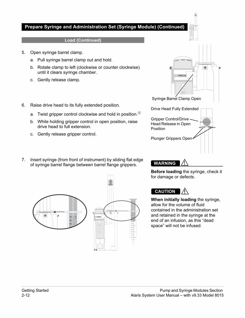
le) (Continued) ALARM INFUSE STANDBY
CHANNELSELECT
CHANNELOFF
PAUSE
RESTART
RATE (mL/h)
ALARM INFUSE STANDBY
CHANNELSELECT
PAUSE
RATE (mL/h)
Syringe Barrel Clamp Open
Drive Head Fully Extended
Gripper Control/Drive Head Release in Open Position
Plunger Grippers Open
Before loading the syringe, check it for damage or defects.
WARNING
When initially loading the syringe, allow for the volume of fluid contained in the administration set and retained in the syringe at the end of an infusion, as this “dead space” will not be infused.
CAUTION
.5. Open syringe barrel clamp.
a. Pull syringe barrel clamp out and hold.
b. Rotate clamp to left (clockwise or counter clockwise) until it clears syringe chamber.
c. Gently release clamp.
6. Raise drive head to its fully extended position.
a. Twist gripper control clockwise and hold in position.
b. While holding gripper control in open position, raise drive head to full extension.
c. Gently release gripper control.
7. Insert syringe (from front of instrument) by sliding flat edge of syringe barrel flange between barrel flange grippers.
Prepare Syringe and Administration Set (Syringe Modu
Load (Continued)
5
10
15
20
25
30
35
40
45
50
55
½
1oz
1½
2oz60
ALARM INFUSE STANDBY
CHANNELSELECT
CHANNELOFF
PAUSE
RESTART
RATE (mL/h)
45
50
552oz60
Getting Started Pump and Syringe Modules Section 2-12 Alaris System User Manual – with v9.33 Model 8015

le) (Continued)
ALARM INFUSE STANDBY
CHANNELSELECT
CHANNELOFF
PAUSE
RESTART
RATE (mL/h)
Ensure that syringe barrel, flange, and plunger are installed and secured correctly. Failure to install syringe correctly can result in uncontrolled fluid flow to the patient, and can cause serious injury or death.
WARNING
Syringe Barrel Clamp Closed
ALARM INFUSE STANDBY
CHANNELSELECT
PAUSE
RATE (mL/h)
20
25
301oz
oz60
35
40
45
50
1½
552
• To avoid an occlusion when loading a smaller size syringe, use extra care to close off administration set tubing and gently lower drive head against syringe plunger.
• For smaller syringes (such as; 1, 3, or 5 mL), stabilize the syringe plunger with thumb and index finger while carefully lowering the drive head. Ensure that the syringe plunger head makes contact with the small black sensor, located on the bottom of the drive head (between the plunger grippers).
CAUTION
8. Lock syringe in place.
a. Pull syringe barrel clamp out and hold.
b. Rotate clamp to right (clockwise or counter clockwise) until it lines up with syringe.
c. Gently release clamp against syringe.
9. Lower drive head and lock plunger in place with plunger grippers.
a. Twist gripper control clockwise and hold in position.
b. While holding gripper control in open position, gently lower drive head until it makes contact with plunger flange.
c. Gently release gripper control.
d. Ensure that plunger grippers lock and hold plunger in place.
Prepare Syringe and Administration Set (Syringe Modu
Load (Continued)
ALARM INFUSE STANDBY
RATE (mL/h)
oz60
40
45
50
1½
552
Gripper Control in Closed Position
Drive Head Flush with Plunger Flange
Plunger Grippers Closed
Pump and Syringe Modules Section Getting StartedAlaris System User Manual – with v9.33 Model 8015 2-13

le) (Continued)
ALARM INFUSE STANDBY
CHANNELSELECT
CHANNELOFF
PAUSE
RESTART
RATE (mL/h)
When the pressure sensing disc is not being used and an occlusion occurs, there is a risk of infusing pressurized buildup of infusates upon correction of the occlusion. To avoid an inadvertent bolus, relieve the pressure before restarting the infusion.
WARNING
Syringe Module
Slot in Pressure Sensing Disc
Housing
Pressure Sensing Disc
Patient Side
Fluid Side
SELECT
CHANNELOFF
PAUSE
RESTART
Pressure Sensing Disc
10. Insert pressure sensing disc (if used), as follows:
a. Orient pressure sensing disc, as follows:
• fluid side up (patient side down)
• cavity forward (membrane toward instrument)
b. Gently slide pressure sensing disc up into slot in pressure sensing disc housing.
c. Apply firm upward pressure on pressure sensing disc (not tubing) until disc snaps into place.
Prepare Syringe and Administration Set (Syringe Modu
Load (Continued)
Getting Started Pump and Syringe Modules Section 2-14 Alaris System User Manual – with v9.33 Model 8015

le) (Continued)
ALARM INFUSE STANDBY
CHANNELSELECT
CHANNELOFF
PAUSE
RESTART
RATE (mL/h)
Electronically prime the syringe pump system before starting an infusion or after replacing a near empty syringe with a replacement syringe. Using the syringe pump's prime feature engages the mechanical components of the pump and decreases the syringe's friction and compliance to minimize startup delays and delivery inaccuracies, especially at low infusion rates. Failure to use the prime feature on the syringe pump after every syringe change and/or tubing change can significantly delay the infusion delivery startup time and lead to delivery inaccuracies.
WARNING
When priming:• Ensure that administration set is
not connected to patient.
• Ensure that air is expelled from line prior to beginning infusion (unexpelled air in line could have serious consequences).
Failure to prime correctly can delay infusion delivery and cause the total volume to be infused to read higher than the actual total delivered to the patient.
WARNING
During priming, the pressure limit alarms are temporarily increased to their maximum level.
CAUTION
The Priming option can be enabled at the time the Alaris System is configured for use. The Priming selection (PRIME soft key) is available only after the syringe and infusion type have been selected, and prior to beginning an infusion.
If a pressure sensing disc is in use, it should be removed from the instrument before priming. See the applicable procedure (as follows) depending on whether or not a pressure sensing disc is used.
Prepare Syringe and Administration Set (Syringe Modu
Load (Continued)
Prime—Using Options Menu
NOTES: The gripper control is spring loaded. When twisted to the open
position and then released, it (and the plunger grippers) returns to the closed position.
The following Syringe module features are available only with extension sets fitted with a pressure sensing disc: Auto PressureBack Off (upon occlusion)Customized Pressure Alarm Settings (see “OcclusionPressure” feature definition)Dynamic Pressure DisplayNumeric Pressure Display Fast Start(See “General Information,” “Features and Displays” for definitions.)
Pump and Syringe Modules Section Getting StartedAlaris System User Manual – with v9.33 Model 8015 2-15

le) (Continued)
ALARM INFUSE STANDBY
CHANNELSELECT
CHANNELOFF
PAUSE
RESTART
RATE (mL/h)
The pressure sensing disc, if left installed during priming, can trap air that might not be totally expelled. To ensure that entrapped air is eliminated, it is recommended that the pressure sensing disc be removed prior to priming and the membrane gently massaged with a finger while priming. After priming is completed, reinstall the pressure sensing disc.
CAUTION
SILENCE
OPTIONS
147
CLEAR
2580
369 ENTER
CANCEL
SYSTEMON
Channel Options 1 of 2
Guardrails Drugs
Pressure Limit - 550 mmHg
A
>Select an Option or EXIT
EXIT
Multidose
Prime Set with Syringe
Guardrails IV Fluids
PAGEDOWN
1. Ensure that administration set is not connected to patient.
2. If installed, remove pressure sensing disc from instrument.
Using a finger, apply firm downward pressure on pressure sensing disc (not tubing) until disc snaps loose from slot in pressure sensing disc housing.
3. Press OPTIONS key.
4. Press Prime Set with Syringe soft key.
Prepare Syringe and Administration Set (Syringe Modu
Prime—Using Options Menu (Continued)
Administration Set With Pressure Sensing Disc
Getting Started Pump and Syringe Modules Section 2-16 Alaris System User Manual – with v9.33 Model 8015

le) (Continued)
ALARM INFUSE STANDBY
CHANNELSELECT
CHANNELOFF
PAUSE
RESTART
RATE (mL/h)
AAA
It is recommended that thePressure Sensing Disc beremoved during priming.
Press CONFIRM andcontinue priming.
>Press CONFIRM
CONFIRM
5
10
15
20
½
Patient Side
A
Prime Set with Syringe
>Press and Hold PRIME
Prime Volume
0 mL
CAUTION: Donot prime withdisposable setconnected topatient!
PRIME EXIT
If pressure sensing disc was not removed prior to pressing Prime Set with Syringe soft key, a pressure sensing disc removal prompt is displayed.
5. Invert pressure sensing disc so that patient side is up.
6. Hold pressure sensing disc between two fingers.
7. Press and hold PRIME soft key.
Prepare Syringe and Administration Set (Syringe Modu
Prime—Using Options Menu (Continued)
Administration Set With Pressure Sensing Disc (Continued)
Pump and Syringe Modules Section Getting StartedAlaris System User Manual – with v9.33 Model 8015 2-17

le) (Continued)
ALARM INFUSE STANDBY
CHANNELSELECT
CHANNELOFF
PAUSE
RESTART
RATE (mL/h)
A
Prime Set with Syringe
>Press and Hold PRIME
Prime Volume
2 mL
CAUTION: Donot prime withdisposable setconnected topatient!
PRIME EXIT
Syringe Module
Slot in Pressure Sensing Disc
Housing
Pressure Sensing Disc
Patient Side
Fluid Side
8. Gently massage pressure sensing disc to ensure that all air is expelled. The disc must remain inverted only until the air is expelled. Continue to gently massage disc throughout priming to ensure that it does not become under- or over- filled.
9. Continue to prime until fluid flows and priming is complete.
Fluid is delivered during priming only while PRIME soft key is pressed. Each press of PRIME soft key delivers up to 2 mL of priming fluid at the maximum rate of the selected syringe per continuous press. To deliver additional amounts, press PRIME soft key again.(See Rate Restriction by Syringe Size: on page 2-157)
10. When priming is complete, release pressure sensing disc and PRIME soft key.
Volume used during priming is displayed but not added to VTBI or VI.
11. Reinstall pressure sensing disc, as follows:
a. Orient pressure sensing disc, as follows:
• fluid side up (patient side down)
• cavity forward (membrane toward instrument)
b. Gently slide pressure sensing disc up into slot in pressure sensing disc housing.
Prepare Syringe and Administration Set (Syringe Modu
Prime—Using Options Menu (Continued)
Administration Set With Pressure Sensing Disc (Continued)
Getting Started Pump and Syringe Modules Section 2-18 Alaris System User Manual – with v9.33 Model 8015

le) (Continued)
ALARM INFUSE STANDBY
CHANNELSELECT
CHANNELOFF
PAUSE
RESTART
RATE (mL/h)
Pressure Sensing Disc
Re-install Pressure SensingDisc.
>Press CONFIRM
CONFIRM
AAA
Channel Options 1 of 2
Guardrails Drugs
Pressure Limit - 550 mmHg
A
>Select an Option or EXIT
EXIT
Multidose
Prime Set with Syringe
Guardrails IV Fluids
PAGEDOWN
c. Apply firm upward pressure on pressure sensing disc (not tubing) until disc snaps into place.
12. To return to main screen, press EXIT soft key.
If EXIT soft key is pressed before pressure sensing disc is reinstalled, a prompt to reinstall pressure sensing disc is displayed.
1. Press OPTIONS key.
2. Press Prime Set with Syringe soft key.
Prepare Syringe and Administration Set (Syringe Modu
Prime—Using Options Menu (Continued)
Administration Set With Pressure Sensing Disc (Continued)
Administration Set With No Pressure Sensing Disc
Pump and Syringe Modules Section Getting StartedAlaris System User Manual – with v9.33 Model 8015 2-19

le) (Continued)
ALARM INFUSE STANDBY
CHANNELSELECT
CHANNELOFF
PAUSE
RESTART
RATE (mL/h)
When priming:• Ensure that administration set is
not connected to patient.
• Ensure that air is expelled from line prior to beginning infusion (unexpelled air in line could have serious consequences).
Failure to prime correctly can delay infusion delivery and cause the total volume to be infused to read higher than the actual total delivered to the patient.
WARNING
3. Press and hold PRIME soft key until fluid flows and priming is complete.
Fluid is delivered during priming only while PRIME soft key is pressed. Each press of PRIME soft key delivers up to 2 mL of priming fluid per continuous press. To deliver additional amounts, press PRIME soft key again.
4. Release PRIME soft key.
Volume used during priming is displayed but not added to VTBI or VI.
5. To return to main screen, press EXIT soft key.
Use the following procedures to manually prime the administration set.
Prepare Syringe and Administration Set (Syringe Modu
Prime—Using Options Menu (Continued)
Prime—Manual
Getting Started Pump and Syringe Modules Section 2-20 Alaris System User Manual – with v9.33 Model 8015

le) (Continued)
ALARM INFUSE STANDBY
CHANNELSELECT
CHANNELOFF
PAUSE
RESTART
RATE (mL/h)
The pressure sensing disc, if left installed during priming, can trap air that might not be totally expelled. To ensure that entrapped air is eliminated, it is recommended that the pressure sensing disc be removed prior to priming and the membrane gently massaged with a finger while priming. After priming is completed, reinstall the pressure sensing disc.
CAUTION
5
10
15
20
½
Patient Side
1. Ensure that administration set is not connected to patient.
2. If installed, remove pressure sensing disc from instrument.
Using a finger, apply firm downward pressure on pressure sensing disc (not tubing) until disc snaps loose from slot in pressure sensing disc housing.
3. Invert pressure sensing disc so that patient side is up.
4. Hold pressure sensing disc between 2 fingers.
5. Slowly prime set while gently massaging pressure sensing disc to ensure that all air is expelled. The disc must remain inverted only until the air is expelled. Continue to gently massage disc throughout priming to ensure that it does not become under- or over-filled.
6. When priming is complete (no air exists), close set clamp.
Prepare Syringe and Administration Set (Syringe Modu
Prime—Manual (Continued)
Administration Set With Pressure Sensing Disc
NOTE: When manually priming (per hospital/facility protocol) and an
administration set having a pressure sensing disc is in use, depress the disc between 2 fingers while priming and prime uphill (distal end of pressure sensing disc/tubing pointing upward).
Pump and Syringe Modules Section Getting StartedAlaris System User Manual – with v9.33 Model 8015 2-21

le) (Continued)
ALARM INFUSE STANDBY
CHANNELSELECT
CHANNELOFF
PAUSE
RESTART
RATE (mL/h)
1. Prime per hospital protocol.
2. When priming is complete (no air exists), close set clamp.
To eliminate mechanical slack or free play, and minimize start-up delays and delivery inaccuracies, especially when infusing at low flow rates, it is recommended that the instrument be primed per the following procedure.
1. Load syringe (see "Load" procedure). If a pressure sensing disc is being used, do not install disc until priming is complete.
2. Select syringe and infusion type (see "Programming" chapter).
3. Open administration set clamp.
4. Prime, as follows, using Priming option (see "Prime -Using Options Menu"):
a. Follow applicable procedure (based on whether or not pressure sensing disc is installed) through step to press and hold PRIME soft key.
b. Prime until fluid drips from end of tubing.
c. Complete procedure (installing pressure sensing disc, if applicable, and exiting options menu).
Prepare Syringe and Administration Set (Syringe Modu
Prime—Manual (Continued)
Administration Set With No Pressure Sensing Disc
Eliminate Mechanical Slack
Getting Started Pump and Syringe Modules Section 2-22 Alaris System User Manual – with v9.33 Model 8015

Programming
The Alaris System can be programmed with Guardrails Suite MX Protection or with no Guardrails Suite MX protection:
• Guardrails Suite MX Protection
• Manual Programming (see page 2-24)
• Programming with Interoperability (see page 2-58)
• Auto-ID (Refer to Section "Auto-ID")
• No Guardrails Suite MX Protection
• Manual Programming Basic Infusion
• Manual Programming Basic Infusion with Drug Calculation
References throughout this procedure to specific drugs and drug doses are for illustration purposes only. Refer to specific drug product labeling for information concerning appropriate administration techniques and dosages.
See "General Information," "Features and Displays" and the PC unit section of this User Manual for information about:
• Displays• Operating Features, Controls, Indicators
The majority of user interface programming is identical for both the Pump module and Syringe module. When referring to both modules, the term "infusion modules" is used. The modules are referred to singularly as the Pump module and the Syringe module.
Introduction
Pump and Syringe Modules Section ProgrammingAlaris System User Manual – with v9.33 Model 8015 2-23

ith Guardrails Suite MX
n
ALARM INFUSE STANDBY
CHANNELSELECT
CHANNELOFF
PAUSE
RESTART
RATE (mL/h)
CHANNELSELECT
CHANNELOFF
RESTART
PAUSE
ALARM INFUSE STANDBY
RATE (mL/h)
The following procedures are to be used only when the drug to be infused is listed in the Drug Library. To access the Drug Library, a hospital-defined best-practice Data Set must be transferred to the Alaris System and the Profile feature must be enabled.
1. Perform following steps (see PC unit section of this manual, "General Setup and Operation," "Start-Up"):
a. Power on system.
b. Choose Yes or No to New Patient?c. Confirm current Profile or select a new Profile.
d. Enter patient identifier, if required.
2. Prepare and load syringe/administration set (see "Getting Started").
3. Prime (see "Getting Started").
Manual Programming w
Manual Programming—Primary Infusio
Manual Programming with Guardrails Suite MX Pump and Syringe Modules Section 2-24 Alaris System User Manual – with v9.33 Model 8015

tinued)
ALARM INFUSE STANDBY
CHANNELSELECT
CHANNELOFF
PAUSE
RESTART
RATE (mL/h)
CHANNELSELECT
CHANNELOFF
RESTART
PAUSE
ALARM INFUSE STANDBY
RATE (mL/h)
Pump Module Syringe Module
ALARM INFUSE STANDBY
CHANNELSELECT
CHANNELOFF
PAUSE
RESTART
RATE (mL/h)
Ensure that the displayed syringe manufacturer and syringe size correctly identify the installed syringe. Mismatches might cause an under-infusion or over-infusion to the patient that could result in serious injury and/or death. For a list of compatible syringes, refer to Compatible Syringes (Syringe Module) on page 2-136 and the AlarisTM Syringe Module Set Compatibility Card.
WARNING
4. Press CHANNEL SELECT key.
5. Syringe module: Select syringe type and size, as follows; otherwise, proceed to step 6. If the installed syringe is loaded correctly, but not recognized, check for the following:
a. If a label is between the syringe barrel and the barrel clamp, make sure that the label does not erroneously enlarge the barrel size of the syringe.
b. If a needle-free valve or other component is added to the syringe, ensure that it is no larger than the diameter of the syringe barrel.
Manual Programming—Primary Infusion (Con
ALARM INFUSE STANDBY
CHANNELSELECT
CHANNELOFF
PAUSE
RESTART
RATE (mL/h)
NOTE:Thick labeling or adding a component to the syringe that is larger than the diameter of the syringe may prevent the device from correctly recognizing the installed syringe. If the issue continues despite the above troubleshooting, send the device to your facility’s biomedical engineering department for servicing.
Pump and Syringe Modules Section Manual Programming with Guardrails Suite MXAlaris System User Manual – with v9.33 Model 8015 2-25

tinued)
BD 30 mL
Monoject 30 mL
>Select Syringe Size
AA Syringe Selection
CONFIRMALL
SYRINGES
ALARM INFUSE STANDBY
CHANNELSELECT
CHANNELOFF
PAUSE
RESTART
RATE (mL/h)
CHANNELSELECT
CHANNELOFF
RESTART
PAUSE
ALARM INFUSE STANDBY
RATE (mL/h)
Selecting an incorrect syringe may cause an under infusion or over infusion to the patient.
WARNING
>Confirm Syringe Size
BD 30 mL
AA Syringe Selection
CONFIRM
Monoject 30 mL
ALLSYRINGES
c. Press soft key next to installed syringe type and size. If a default syringe list has been enabled and correct syringe cannot be found, press the ALL SYRINGES soft key to select from a list of all compatible syringes.
d. To accept, press CONFIRM soft key.
6. Start applicable infusion, as described in following procedures:
Continuous InfusionBolus DoseIntermittent InfusionFluid Infusion
Manual Programming—Primary Infusion (Con
NOTE: At the start of a Syringe module infusion program, the system
prompts to select and confirm the syringe type and size. The system automatically detects the syringe size, and lists syringe types and sizes that most closely match the installed syringe. If the syringe is not recognized, Syringe not recognized is displayed.
NOTE:It is possible to program an infusion with a rate that is displayed with two decimal places (one-hundredth of a mL per hour) on the PC unit for the Pump module. However, due to space limitations on the Pump module rate display, the rate is displayed to the nearest one-tenth of a mL per hour on the Pump module. This value is only used for display purposes and the Pump module is actually infusing at the more precise rate noted on the PC unit.
Manual Programming with Guardrails Suite MX Pump and Syringe Modules Section 2-26 Alaris System User Manual – with v9.33 Model 8015

tinued)
ALARM INFUSE STANDBY
CHANNELSELECT
CHANNELOFF
PAUSE
RESTART
RATE (mL/h)
CHANNELSELECT
CHANNELOFF
RESTART
PAUSE
ALARM INFUSE STANDBY
RATE (mL/h)
A
>Select an Option or EXIT
EXIT
Basic infusion
Guardrails Drugs
RESTORE
Infusion Menu
Guardrails IV Fluids
EXIT
A
PAGEDOWN
A
>Select Drug
DOBUTamine
Heparin
K-O
F-J
P-T
U-Z
A-E
Guardrails DrugsAdult ICU
DOPamine
DRUGCALC
Alteplase
AMIODArone
EXIT
AA
>Select Therapy Type
Alteplase
MI
Stroke
DRUGLIBRARY
Guardrails DrugsAdult ICU
When using a drug listed in the Drug Library, the drug parameters are automatically calculated, based on:
• drug selected• weight entry (if required)• rate or dose entry• VTBI entry (Syringe module—if other than All)
1. Press Guardrails Drugs soft key.
2. Press soft key next to desired drug.
• To view additional drugs/concentrations, press a soft key next to a letter group to navigate through alphabet, and/or PAGE UP and PAGE DOWN soft keys.
• If applicable, an optional hospital-defined therapy or clinical indication for delivery of this infusion could appear—as in illustrated example, which reflects use of Alteplase. Different limits can be defined for same drug with different therapeutic indications.
Therapy indication appears on drug or IV fluid confirmation screen. Once drug or IV fluid has been confirmed, therapy indication appears in title bar.
Manual Programming—Primary Infusion (Con
Continuous Infusion
Pump and Syringe Modules Section Manual Programming with Guardrails Suite MXAlaris System User Manual – with v9.33 Model 8015 2-27

tinued)
ALARM INFUSE STANDBY
CHANNELSELECT
CHANNELOFF
PAUSE
RESTART
RATE (mL/h)
CHANNELSELECT
CHANNELOFF
RESTART
PAUSE
ALARM INFUSE STANDBY
RATE (mL/h)
EXIT
AA
>Select Dose Unit Type
HeparinNon-Weight based dosing
DRUGLIBRARY
Guardrails DrugsAdult ICU
®
Weight based dosing
EXIT
AA
>Select Concentration
DOPamine400mg/250mL
DRUGLIBRARY
Guardrails DrugsAdult ICU
800mg/250mL
• If applicable, a weight-based or non weight-based option for delivery of this infusion could appear (as in illustrated example, which reflects use of Heparin).
• If applicable, multiple concentration listings for delivery of this infusion could appear (as in illustrated example, which reflects use of Dopamine).
3. To continue programming, press Yes soft key.
Bolus Dose units appear if Bolus Dose is enabled.OR
To change selection, press No soft key.
Manual Programming—Primary Infusion (Con
Continuous Infusion (Continued)
Manual Programming with Guardrails Suite MX Pump and Syringe Modules Section 2-28 Alaris System User Manual – with v9.33 Model 8015

tinued)
ALARM INFUSE STANDBY
CHANNELSELECT
CHANNELOFF
PAUSE
RESTART
RATE (mL/h)
CHANNELSELECT
CHANNELOFF
RESTART
PAUSE
ALARM INFUSE STANDBY
RATE (mL/h)
A
>Press CONFIRM
Clinical Advisory:
CONFIRM
AlteplaseStroke
This dosing is for AcuteIschemic STROKE
ADRUG
AMOUNT
DILUENTVOLUME
100 mg
100 mL
[Conc]: 1 mg/mL
hour
mg/kg/h
>Press NEXT to Confirm
NEXT
TIMEUNITS
DOSINGUNITS
UsedPATIENTWEIGHT
DRUGLIBRARY
AlteplaseStroke
ADRUG
AMOUNT
DILUENTVOLUME 100 mL
[Conc]: 1 mg/mL
hour
mg/kg/h
>Enter Patient Weight
TIMEUNITS
DOSINGUNITS
PATIENTWEIGHT _ _ _ _ kg
100 mg
DRUGLIBRARY
AlteplaseStroke
• If YES was selected and facility has defined a Clinical Advisory for that drug, a message appears. To indicate information has been noted and continue programming, press CONFIRM soft key.
• If Yes was selected to continue programming, drug amount and diluent volume (if defined in Drug Library) are automatically entered for selected drug.
• If selected drug had "_ _ / _ _ mL" concentration, drug amount and diluent volume need to be entered.
• If selected drug is not weight-based, Not Used is displayed in PATIENT WEIGHT field.
• If hospital/facility practice guidelines identify selected drug as weight-based, prompt for a patient weight in kilograms appears (as in illustrated example, which reflects use of Alteplase).
4. Verify correct parameters and press NEXT soft key to confirm.
Manual Programming—Primary Infusion (Con
Continuous Infusion (Continued)
Pump and Syringe Modules Section Manual Programming with Guardrails Suite MXAlaris System User Manual – with v9.33 Model 8015 2-29

tinued)
ALARM INFUSE STANDBY
CHANNELSELECT
CHANNELOFF
PAUSE
RESTART
RATE (mL/h)
CHANNELSELECT
CHANNELOFF
RESTART
PAUSE
ALARM INFUSE STANDBY
RATE (mL/h)
AAA
RATE
>Select Rate or Dose
VTBI
CONTINUOUS INFUSION
DOSE _ _ _ _ _ mg/kg/h
[Conc]: 1 mg/mL
_ _ _ mL/h
SETUP
_ _ _ _ mL
BOLUS
AlteplaseStroke
R
AAA
RATE
VTBI
CONTINUOUS INFUSION
DOSE _ 0.81 mg/kg/h
[Conc]: 1 mg/mL
56.7 mL/h
SETUP BOLUS
_ _ _ _ mL
>Select VTBI
AlteplaseStroke
5. An optional hospital-defined and editable starting value for Continuous Infusion dose might already be entered.
OR
To make a rate or dose entry, press applicable soft key, RATE or DOSE, and use numeric data entry keys (other value is calculated and displayed).
6. To enter volume to be infused, press VTBI soft key and enter value.
• Pump module:
◦ When VTBI is less than 10 mL, entry can be to two decimal places (one-hundredth of a mL).
◦ In Drug Calculation mode, system infuses at calculated rate rounded to nearest one-hundredth of a mL per hour (as displayed on the programming screen on the PC unit). The rate shown in Rate Display on the Pump module is rounded to nearest one-tenth of a mL per hour.
• BOLUS soft key appears only if Bolus Dose is enabled within selected Profile, drug is bolusable, and a VTBI is entered.
Manual Programming—Primary Infusion (Con
Continuous Infusion (Continued)
O
CHANNELSELECT
CHANNELOFF
RESTART
PAUSE
ALARM INFUSE STANDBY
RATE (mL/h)
Manual Programming with Guardrails Suite MX Pump and Syringe Modules Section 2-30 Alaris System User Manual – with v9.33 Model 8015

tinued)
ALARM INFUSE STANDBY
CHANNELSELECT
CHANNELOFF
PAUSE
RESTART
RATE (mL/h)
CHANNELSELECT
CHANNELOFF
RESTART
PAUSE
ALARM INFUSE STANDBY
RATE (mL/h)
AAA
RATE
VTBI
CONTINUOUS INFUSION
DOSE _ 0.81 mg/kg/h
[Conc]: 1 mg/mL
56.7 mL/h
SETUP BOLUS
ALL
>Select VTBI
AlteplaseStroke
Available:(55.5 mL)
STARTPAUSE
AAA
RATE
VTBI
CONTINUOUS INFUSION
DOSE 0.81 mg/kg/h
[Conc]: 1 mg/mL
SETUP BOLUS
100 mL
STARTPAUSE
>Press START
56.7 mL/h
AlteplaseStroke
• Syringe module:
◦ If ALL Mode is enabled for syringe configuration in Data Set, ALL is displayed in VTBI field and estimated available volume in syringe is displayed.
ORIf ALL Mode is disabled for syringe configuration in Data Set, estimated available volume in syringe is displayed when VTBI soft key is pressed.
◦ To enter or change a numeric VTBI value, press VTBI soft key and enter value.
◦ To deliver entire contents of syringe: Keep an ALL VTBI value, or press ALL soft key to change a numeric VTBI value to ALL.
7. Verify correct parameters and press START soft key.
• For a Continuous Infusion, the drug name and dose will scroll on the module Message Display
Manual Programming—Primary Infusion (Con
Continuous Infusion (Continued)
ALARM INFUSE STANDBY
CHANNELSELECT
CHANNELOFF
PAUSE
RESTART
RATE (mL/h)
Pump and Syringe Modules Section Manual Programming with Guardrails Suite MXAlaris System User Manual – with v9.33 Model 8015 2-31

tinued)
ALARM INFUSE STANDBY
CHANNELSELECT
CHANNELOFF
PAUSE
RESTART
RATE (mL/h)
CHANNELSELECT
CHANNELOFF
RESTART
PAUSE
ALARM INFUSE STANDBY
RATE (mL/h)
A
>Press Yes or No
Yes
No
Dose exceedsGuardrail limit of0.81 mg/kg/h.Proceed?
AlteplaseStroke
A
>Press REPROGRAM
ReprogramDose exceedsGuardrails hardlimit of 0.82 mg/kg/h.
AlteplaseStroke
VOLUMEINFUSED
AUDIOADJUST
Midtown HospitalAdult ICU
A VTBI = 250 mL G
• If the programmed continuous dose infusion is outside the Soft Limit for that care area, an audio alert sounds and a visual prompt appears before programming can continue. If Yes soft key is pressed, programming continues; if No soft key is pressed, infusion needs to be reprogrammed.
• If the programmed continuous dose infusion is outside the Hard Limit for that care area, an audio alert sounds and a visual prompt appears before programming can continue. Infusion needs to be reprogrammed.
• If a dose outside of the Soft Limits has been entered and verified as correct, Message Display also shows either "LLL" for a low dose or "" for a high dose.
• If a Soft Limit is overridden, G icon is displayed. When G soft key is pressed, all applicable out-of-range limits are listed.
Manual Programming—Primary Infusion (Con
Continuous Infusion (Continued)
Manual Programming with Guardrails Suite MX Pump and Syringe Modules Section 2-32 Alaris System User Manual – with v9.33 Model 8015

tinued)
ALARM INFUSE STANDBY
CHANNELSELECT
CHANNELOFF
PAUSE
RESTART
RATE (mL/h)
CHANNELSELECT
CHANNELOFF
RESTART
PAUSE
ALARM INFUSE STANDBY
RATE (mL/h)
8. Syringe module:
• Unclamp tubing and attach administration set to patient.
• Unclamping tubing and starting infusion before attaching administration set to patient minimizes any potential bolus that can be released from pressure built up in set due to normal syringe loading and priming.
A Bolus Dose can be programmed at the beginning of, or during, a continuous infusion. The drug being programmed must be a bolusable drug selected from the Drug Library or a non-library drug, as described in the following procedures.
1. Set up infusion as described in "Continuous Infusion" procedure, but do not start infusion.
Manual Programming—Primary Infusion (Con
Continuous Infusion (Continued)
Bolus Dose
ALARM INFUSE STANDBY
CHANNELSELECT
CHANNELOFF
PAUSE
RESTART
RATE (mL/h)
NOTES: The facility can choose to pre-populate standard drug
concentrations, or leave a custom concentration (_ _ / _ _ mL) and allow the clinician to enter the desired concentration.
Patient weight can be edited during a Continuous Infusion. Once a patient weight is entered and an infusion is started for
any module, the patient weight is automatically entered for any additional weight-based calculation. The patient weight remains an editable field, therefore patient weight can be adjusted for any module. Changing the patient weight on one module does not affect the patient weight on any other module.
NOTE:It is possible to program an infusion with a rate that is displayed with two decimal places (one-hundredth of a mL per hour) on the PC unit for the Pump module. However, due to space limitations on the Pump module rate display, the rate is displayed to the nearest one-tenth of a mL per hour on the Pump module. This value is only used for display purposes and the Pump module is actually infusing at the more precise rate noted on the PC unit.
Pump and Syringe Modules Section Manual Programming with Guardrails Suite MXAlaris System User Manual – with v9.33 Model 8015 2-33

tinued)
ALARM INFUSE STANDBY
CHANNELSELECT
CHANNELOFF
PAUSE
RESTART
RATE (mL/h)
CHANNELSELECT
CHANNELOFF
RESTART
PAUSE
ALARM INFUSE STANDBY
RATE (mL/h)
AAA
RATE
VTBI
CONTINUOUS INFUSION
DOSE 0.81 mg/kg/h
[Conc]: 1 mg/mL
SETUP BOLUS
100 mL
STARTPAUSE
>Press START
56.7 mL/h
AlteplaseStroke
>Enter Bolus Dose
_ _ _ _ unit/kg
AAA
DOSE
PATIENTWEIGHT
BOLUS DOSE
DURATION
[Conc]: 1 mg/mL
SETUP
AlteplaseStroke
CONT-INUOUS
2. Press BOLUS soft key.
• If the programmed continuous dose infusion is outside the Soft Limit for that care area, an audio alert sounds and a visual prompt appears before programming can continue. If Yes soft key is pressed, programming continues; if No soft key is pressed, infusion needs to be reprogrammed.
• If the programmed continuous dose infusion is outside the Hard Limit for that care area, an audio alert sounds and a visual prompt appears before programming can continue. The infusion needs to be reprogrammed.
3. An optional hospital-defined and editable starting value for Bolus Dose and/or bolus rate duration might already be entered.
OR
To enter Bolus Dose, use numeric data entry keys.
• After a Bolus Dose and weight (if used) are entered, bolus VTBI and concentration [conc] alternate in Main Display.
• If no weight has previously been programmed in system and Bolus Dose is weight-based, weight entry is empty.
• If the programmed continuous dose is weight-based, programmed weight is displayed.
• If Bolus Dose is not weight-based, Not Used is displayed in PATIENT WEIGHT field.
• A Bolus Dose can be either weight based or non weight-based independent of whether the Continuous Infusion is weight based or non weight-based.
4. Enter or change patient weight (if used), use applicable following procedure, depending on whether or not continuous dose is weight-based.
Manual Programming—Primary Infusion (Con
Bolus Dose (Continued)
Manual Programming with Guardrails Suite MX Pump and Syringe Modules Section 2-34 Alaris System User Manual – with v9.33 Model 8015

tinued)
ALARM INFUSE STANDBY
CHANNELSELECT
CHANNELOFF
PAUSE
RESTART
RATE (mL/h)
CHANNELSELECT
CHANNELOFF
RESTART
PAUSE
ALARM INFUSE STANDBY
RATE (mL/h)
AAA
CONTINUOUS INFUSION
Drug CalculationHeparinA
Dose will recalculatebased on new weight.Adjust Dose or Rateif required.Accept weight change?
>Select Yes or No
Yes
No
AlteplaseStroke
a. To enter a weight when continuous dose is not weight- based:
• Press PATIENT WEIGHT soft key
• To enter patient weight, use numeric data entry keys.OR
b. To change weight when continuous dose is weight-based:
• Press SETUP soft key.
• Press PATIENT WEIGHT soft key.
• To change patient weight, use numeric data entry keys.
• Press NEXT soft key.
If a Continuous Infusion is running, a prompt to confirm weight change appears.
• Press BOLUS soft key.
• To enter Bolus Dose, use numeric data entry keys.
5. Press DURATION soft key.
Manual Programming—Primary Infusion (Con
Bolus Dose (Continued)
Pump and Syringe Modules Section Manual Programming with Guardrails Suite MXAlaris System User Manual – with v9.33 Model 8015 2-35

tinued)
ALARM INFUSE STANDBY
CHANNELSELECT
CHANNELOFF
PAUSE
RESTART
RATE (mL/h)
CHANNELSELECT
CHANNELOFF
RESTART
PAUSE
ALARM INFUSE STANDBY
RATE (mL/h)
0.090 mg/kg
AAA
DOSE
PATIENTWEIGHT
BOLUS DOSE
DURATION
SETUP
>Enter Duration
70 kg
RapidBolus_ _ min
(420 mL/h)
TOTAL DOSE = 6.3 mg
BOLUS VTBI = 6.3 mL
CONT-INUOUS
AlteplaseStroke
OR
5 mcg/kg
AAA
DOSE
PATIENTWEIGHT
BOLUS DOSE
DURATION
[Conc]: 800 mcg/mL
SETUP
>Press Start to BeginInfusing Bolus Dose
71 kg
<1 min
STARTPAUSECONT-
INUOUS
Guardrails Drug LibraryDopamine
BOLUS VTBI = 50.0 mL
AAA
DOSE
BOLUS DOSE
DURATION
[Conc]: 1 mg/mL
SETUP
>Press START to BeginInfusing Bolus Dose
1 min
STARTPAUSECONT-
INUOUS
PATIENTWEIGHT
INFUSE AT: 0.09 mg/kg/min
0.090 mg/kg
70 kg
RapidBolus
(420 mL/h)
AlteplaseStroke
6. To enter bolus duration, use numeric data entry keys.OR
To deliver Bolus Dose at maximum safe rate possible for selected drug and setup, and automatically calculate bolus duration, press Rapid Bolus soft key.
• TOTAL DOSE alternates with INFUSE AT rate.
7. Verify correct parameters and press START soft key.
• If the programmed Bolus Dose and/or Bolus Dose duration is outside the Soft Limit for that care area, an audio alert sounds and a visual prompt appears before programming can continue. If Yes soft key is pressed, programming continues; if No soft key is pressed, infusion needs to be reprogrammed.
• If the programmed Bolus Dose and/or Bolus Dose duration is outside the Hard Limit for that care area, an audio alert sounds and a visual prompt appears before programming can continue. Infusion needs to be reprogrammed.
Manual Programming—Primary Infusion (Con
Bolus Dose (Continued)
Manual Programming with Guardrails Suite MX Pump and Syringe Modules Section 2-36 Alaris System User Manual – with v9.33 Model 8015

tinued)
ALARM INFUSE STANDBY
CHANNELSELECT
CHANNELOFF
PAUSE
RESTART
RATE (mL/h)
CHANNELSELECT
CHANNELOFF
RESTART
PAUSE
ALARM INFUSE STANDBY
RATE (mL/h)
AAA
DoseRemaining:
Time Left: 1 min
STOPBOLUS
STARTPAUSE
Pt. Weight: 70 kg
BOLUS DOSE
TOTAL DOSE = 6.3 mg
>Press START to ContinueInfusing Bolus Dose
BOLUS VTBI = 6.3 mL
0.090 mg/kg
AlteplaseStroke
• If a Bolus Dose outside of Soft Limits has been entered and verified as correct, Message Display also shows either "LLL" for a low dose or "" for a high dose.
• If a Soft Limit is overridden, G icon is displayed. When G soft key is pressed, all applicable out-of-range limits are listed.
8. Syringe module:
• If Bolus Dose was programmed at beginning of infusion, unclamp tubing and attach administration set to patient.
• Unclamping tubing and starting infusion before attaching administration set to patient minimizes any potential bolus that can be released from pressure built up in set due to normal syringe loading and priming.
The display examples in this procedure represent stopping a Bolus Dose which was programmed using the Drug Library. Even where the displays are different when stopping a Bolus Dose which was programmed using a non-library drug, the procedure is the same.
1. Press CHANNEL SELECT key.
2. Press STOP BOLUS soft key.
Manual Programming—Primary Infusion (Con
Bolus Dose (Continued)
Stop Bolus Dose
ALARM INFUSE STANDBY
CHANNELSELECT
CHANNELOFF
PAUSE
RESTART
RATE (mL/h)
Pump and Syringe Modules Section Manual Programming with Guardrails Suite MXAlaris System User Manual – with v9.33 Model 8015 2-37

tinued)
ALARM INFUSE STANDBY
CHANNELSELECT
CHANNELOFF
PAUSE
RESTART
RATE (mL/h)
CHANNELSELECT
CHANNELOFF
RESTART
PAUSE
ALARM INFUSE STANDBY
RATE (mL/h)
A
>Press Yes or No
Yes
No
Stop Bolus and StartContinuous infusion?
AlteplaseStroke
CHANNELSELECT
CHANNELOFF
RESTART
PAUSE
3. To stop bolus and start Continuous Infusion, press Yes soft key.
4. To stop Continuous Infusion, press and hold CHANNEL OFF key until a beep is heard (approximately 1.5 seconds).
A Bolus Dose can be restored after it has completed, either prior to or after the module has been turned off, as indicated in the following procedures.
The display examples in this procedure represent restoring a Bolus Dose which was programmed using the Drug Library. Even where the displays are different when restoring a Bolus Dose which was programmed using a non-library drug, the procedure is the same.
1. Bolus Dose completed - module not turned off:
a. Press CHANNEL SELECT key.
b. Verify infusion parameters and press BOLUS soft key.
Manual Programming—Primary Infusion (Con
Bolus Dose (Continued)
Stop Bolus Dose (Continued)
Restore Bolus Dose
Manual Programming with Guardrails Suite MX Pump and Syringe Modules Section 2-38 Alaris System User Manual – with v9.33 Model 8015

tinued)
ALARM INFUSE STANDBY
CHANNELSELECT
CHANNELOFF
PAUSE
RESTART
RATE (mL/h)
CHANNELSELECT
CHANNELOFF
RESTART
PAUSE
ALARM INFUSE STANDBY
RATE (mL/h)
c. Press RESTORE soft key.
d. Verify dosing parameters and press START soft key.
2. Bolus Dose completed - module turned off:
a. Press CHANNEL SELECT key.
b. Press RESTORE soft key.
c. Verify parameters and press NEXT soft key.
d. Verify infusion parameters and press BOLUS soft key.
e. Press RESTORE soft key.
f. Verify dosing parameters and press START soft key.
Manual Programming—Primary Infusion (Con
Bolus Dose (Continued)
Restore Bolus Dose (Continued)
NOTES: If the Bolus Dose feature is enabled, the BOLUS soft key
appears in the Continuous Infusion screen and becomes active when a VTBI is entered.
The bolus VTBI cannot exceed the programmed Continuous Infusion VTBI.
Programming and starting a Bolus Dose deletes any programmed delay.
If no continuous rate is entered or if the Bolus Dose VTBI equals the Continuous Infusion VTBI, the infusion ends when the bolus has been delivered. No KVO infusion follows.
To see details during the bolus infusion, press the CHANNEL SELECT key.
The Pump module keypad is used in the illustration but the key is the same for the Syringe module.
Pump and Syringe Modules Section Manual Programming with Guardrails Suite MXAlaris System User Manual – with v9.33 Model 8015 2-39

tinued)
ALARM INFUSE STANDBY
CHANNELSELECT
CHANNELOFF
PAUSE
RESTART
RATE (mL/h)
CHANNELSELECT
CHANNELOFF
RESTART
PAUSE
ALARM INFUSE STANDBY
RATE (mL/h)
EXIT
A
PAGEDOWN
A
>Select Drug
Amifostine
Bleomycin
Cytarabine
Daunorbicin
K-O
F-J
P-T
U-Z
A-E
Guardrails DrugsPeds Oncology
Azathioprine
DRUGCALC
A
>Press Yes or No
Methotrexate_ _ _ mg/_ _ _mL wasselected.Is this correct?
Yes
No
mg/m2DOSING
UNITS
Guardrails Drug SetupPeds Oncology
When using a drug listed in the Drug Library, the drug parameters are automatically delivered, based on:
• drug selected• weight or body surface area (BSA) entry (if required)• dose entry• rate or duration dose entry• VTBI entry
Syringe module: The KVO option is disabled when an Intermittent Infusion is programmed.
1. Press Guardrails Drugs soft key.
2. Press soft key next to desired drug.
• To view additional drugs, press a soft key next to a letter group to navigate through alphabet, and/or PAGE UP and PAGE DOWN soft keys.
• If applicable, an optional hospital-defined therapy or clinical indication for delivery of this infusion could appear. Different limits can be defined for same drug with different therapeutic indications.
• If applicable, a weight-based, non weight-based, or BSA-based option for delivery of this infusion could appear.
• If applicable, multiple concentration listings for delivery of this infusion could appear.
3. To continue programming, press Yes soft key.
OR
To change selection, press No soft key.
Manual Programming—Primary Infusion (Con
Intermittent Infusion
Manual Programming with Guardrails Suite MX Pump and Syringe Modules Section 2-40 Alaris System User Manual – with v9.33 Model 8015
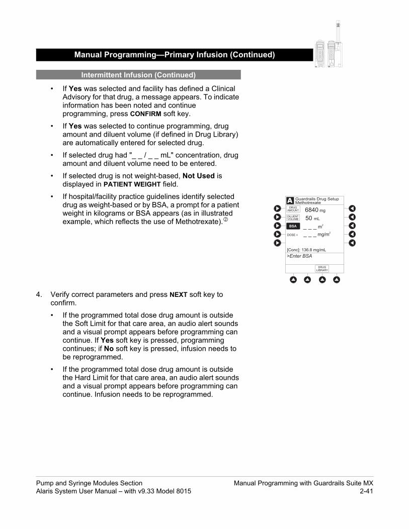
tinued)
ALARM INFUSE STANDBY
CHANNELSELECT
CHANNELOFF
PAUSE
RESTART
RATE (mL/h)
CHANNELSELECT
CHANNELOFF
RESTART
PAUSE
ALARM INFUSE STANDBY
RATE (mL/h)
ADRUG
AMOUNT
DILUENTVOLUME
6840 mg
50 mL
[Conc]: 136.8 mg/mL
>Enter BSA
DOSE = _ _ _ mg/m2
Guardrails Drug SetupMethotrexate
BSA _ _ _ m2
DRUGLIBRARY
• If Yes was selected and facility has defined a Clinical Advisory for that drug, a message appears. To indicate information has been noted and continue programming, press CONFIRM soft key.
• If Yes was selected to continue programming, drug amount and diluent volume (if defined in Drug Library) are automatically entered for selected drug.
• If selected drug had "_ _ / _ _ mL" concentration, drug amount and diluent volume need to be entered.
• If selected drug is not weight-based, Not Used is displayed in PATIENT WEIGHT field.
• If hospital/facility practice guidelines identify selected drug as weight-based or by BSA, a prompt for a patient weight in kilograms or BSA appears (as in illustrated example, which reflects the use of Methotrexate).
4. Verify correct parameters and press NEXT soft key to confirm.
• If the programmed total dose drug amount is outside the Soft Limit for that care area, an audio alert sounds and a visual prompt appears before programming can continue. If Yes soft key is pressed, programming continues; if No soft key is pressed, infusion needs to be reprogrammed.
• If the programmed total dose drug amount is outside the Hard Limit for that care area, an audio alert sounds and a visual prompt appears before programming can continue. Infusion needs to be reprogrammed.
Manual Programming—Primary Infusion (Con
Intermittent Infusion (Continued)
Pump and Syringe Modules Section Manual Programming with Guardrails Suite MXAlaris System User Manual – with v9.33 Model 8015 2-41

tinued)
ALARM INFUSE STANDBY
CHANNELSELECT
CHANNELOFF
PAUSE
RESTART
RATE (mL/h)
CHANNELSELECT
CHANNELOFF
RESTART
PAUSE
ALARM INFUSE STANDBY
RATE (mL/h)
[Conc]: 136.8 mg/mL
_ _ _ mL/h
_ _ _ _h min
RATE =
VTBI
DURATION
RATEVOLUME
A
PRIMARY INFUSION
DOSE =
SETUP
1200 mg/m2
ALL
Guardrails Drug SetupMethotrexate
Available:(49.2 mL)
>Select DURATION
• If a dose outside of Soft Limits has been entered and verified as correct, Message Display also shows either "LLL" for a low dose or "" for a high dose.
• If a Soft Limit is overridden, G icon is displayed. When G soft key is pressed, all applicable out-of-range limits are listed.
5. VTBI entry:
• Pump module:
◦ When VTBI is less than 10 mL, entry can be to two decimal places (one-hundredth of a mL).
◦ VTBI is pre-populated with diluent volume of infusion. To change VTBI, press VTBI soft key and enter new value.
• Syringe module:
◦ If ALL Mode is enabled for syringe configuration in Data Set, ALL is displayed in VTBI field and estimated available volume in syringe is displayed.
ORIf ALL Mode is disabled for syringe configuration in Data Set, estimated available volume in syringe is displayed when VTBI soft key is pressed.
◦ To enter or change a numeric VTBI value, press VTBI soft key and enter value.
◦ To deliver entire contents of syringe: Keep an ALL VTBI value, or press ALL soft key to change a numeric VTBI value to ALL.
Manual Programming—Primary Infusion (Con
Intermittent Infusion (Continued)
CHANNELSELECT
CHANNELOFF
RESTART
PAUSE
ALARM INFUSE STANDBY
RATE (mL/h)
ALARM INFUSE STANDBY
CHANNELSELECT
CHANNELOFF
PAUSE
RESTART
RATE (mL/h)
Manual Programming with Guardrails Suite MX Pump and Syringe Modules Section 2-42 Alaris System User Manual – with v9.33 Model 8015

tinued)
ALARM INFUSE STANDBY
CHANNELSELECT
CHANNELOFF
PAUSE
RESTART
RATE (mL/h)
CHANNELSELECT
CHANNELOFF
RESTART
PAUSE
ALARM INFUSE STANDBY
RATE (mL/h)
[Conc]: 136.8 mg/mL
4 mL/h
6:00 hh:mm
RATE =
VTBI
DURATION
RATEVOLUME
A
>Press START
PRIMARY INFUSION
DOSE =
SETUP
1200 mg/m2
STARTDELAYOPTIONS
ALL
Guardrails Drug SetupMethotrexate
Available:(49.2 mL)
OR
6. If an optional hospital-defined and editable starting value for intermittent duration is not already entered, enter duration or rate, as follows:
• To enter duration, press DURATION soft key and use numeric data entry keys (rate value is calculated and displayed).
• To enter rate, press RATE VOLUME soft key and enter infusion rate.
7. Verify correct parameters and press START soft key.
• If the programmed duration is outside the Soft Limit for that care area, an audio alert sounds and a visual prompt appears before programming can continue. If Yes soft key is pressed, programming continues; if No soft key is pressed, infusion needs to be reprogrammed.
• If the programmed duration is outside the Hard Limit for that care area, an audio alert sounds and a visual prompt appears before programming can continue. Infusion needs to be reprogrammed.
• If a Soft Limit is overridden, G icon is displayed. When G soft key is pressed, all applicable out-of-range limits are listed.
• For an Intermittent Infusion, the drug name and dose will scroll on the module Message Display.
Manual Programming—Primary Infusion (Con
Intermittent Infusion (Continued)
NOTE:For an Intermittent Infusion, depending on how the drug library is programmed, the dose may display as a total dose, drug amount/kg or drug amount/BSA.
Pump and Syringe Modules Section Manual Programming with Guardrails Suite MXAlaris System User Manual – with v9.33 Model 8015 2-43

tinued)
ALARM INFUSE STANDBY
CHANNELSELECT
CHANNELOFF
PAUSE
RESTART
RATE (mL/h)
CHANNELSELECT
CHANNELOFF
RESTART
PAUSE
ALARM INFUSE STANDBY
RATE (mL/h)
8. Syringe module:
• Unclamp tubing and attach administration set to patient.
• Unclamping tubing and starting infusion before attaching administration set to patient minimizes any potential bolus that can be released from pressure built up in set due to normal syringe loading and priming.
Manual Programming—Primary Infusion (Con
Intermittent Infusion (Continued)
ALARM INFUSE STANDBY
CHANNELSELECT
CHANNELOFF
PAUSE
RESTART
RATE (mL/h)
NOTES: The facility can choose to prepopulate standard drug
concentrations, or leave a custom concentration (_ _ / _ _ mL) and allow the clinician to enter the desired concentration.
Patient weight or BSA is not editable during an Intermittent Infusion.
Once a patient weight or BSA is entered and the infusion started, the patient weight or BSA is automatically entered for any additional weight-based or BSA calculation. Prior to the start of an intermittent infusion, the patient weight or BSA remains an editable field so that patient weight or BSA can be adjusted for any module. Changing the patient weight or BSA on one module will not affect the patient weight or BSA on any other module.
NOTE:It is possible to program an infusion with a rate that is displayed with two decimal places (one-hundredth of a mL per hour) on the PC unit for the Pump module. However, due to space limitations on the Pump module rate display, the rate is displayed to the nearest one-tenth of a mL per hour on the Pump module. This value is only used for display purposes and the Pump module is actually infusing at the more precise rate noted on the PC unit.
Manual Programming with Guardrails Suite MX Pump and Syringe Modules Section 2-44 Alaris System User Manual – with v9.33 Model 8015

tinued)
ALARM INFUSE STANDBY
CHANNELSELECT
CHANNELOFF
PAUSE
RESTART
RATE (mL/h)
CHANNELSELECT
CHANNELOFF
RESTART
PAUSE
ALARM INFUSE STANDBY
RATE (mL/h)
A
PAGEDOWN
A
>Select IV Fluid
Packed Red Cells
TPN R
Q
S
T
P
Guardrails IV FluidsOncology
Platelets
PAGEUP
Guardrails Fluid SetupOncologyA
>Press Yes or No
TPNwas selected.Is this correct?
Yes
No
A
VOLUMEDURATION
TPNGuardrails Fluid Setup
RATE
VTBI
_ _ _ mL/h
PRIMARY INFUSION
1000 mL
>Select RATE
1. Press Guardrails IV Fluids soft key.
2. Press soft key next to IV fluid to be delivered.
3. To confirm selection, press Yes soft key.OR
To return to IV Fluid library list, press No soft key.
If Yes was selected and facility has defined a Clinical Advisory for that drug, a message appears. To indicate information has been noted and continue programming, press CONFIRM soft key.
4. Start applicable infusion, as described in following procedures:
Rate/Volume InfusionVolume/Duration Infusion
1. To enter flow rate, press RATE soft key and use numeric data entry keys.
Manual Programming—Primary Infusion (Con
Fluid Infusion
Rate/Volume Infusion
Pump and Syringe Modules Section Manual Programming with Guardrails Suite MXAlaris System User Manual – with v9.33 Model 8015 2-45

tinued)
ALARM INFUSE STANDBY
CHANNELSELECT
CHANNELOFF
PAUSE
RESTART
RATE (mL/h)
CHANNELSELECT
CHANNELOFF
RESTART
PAUSE
ALARM INFUSE STANDBY
RATE (mL/h)
>Enter VTBI
A
START
TPNGuardrails Fluid Setup
VTBI
64 mL/hRATE
PRIMARY INFUSION
VOLUMEDURATION
1000 mL
PAUSE
A
START
fat emulsion 20%Guardrails Fluid Setup
VTBI
0.8 mL/hRATE
PRIMARY INFUSION
VOLUMEDURATION
ALL
>Press START
Available:(19.9 mL)
PAUSE
2. To enter VTBI, press VTBI soft key and use numeric data entry keys.
• Syringe module:
◦ If ALL Mode is enabled for syringe configuration in Data Set, ALL is displayed in VTBI field and estimated available volume in syringe is displayed.
OR
If ALL Mode is disabled for syringe configuration in Data Set, VTBI ALL option is not available and estimated available volume in syringe is displayed when VTBI soft key is pressed.
◦ To enter or change a numeric VTBI value, press VTBI soft key and use numeric data entry keys.
◦ To deliver entire contents of syringe: Keep an ALL VTBI value, or press ALL soft key to change a numeric VTBI value to ALL.
Manual Programming—Primary Infusion (Con
Fluid Infusion (Continued)
Rate/Volume Infusion (Continued)
ALARM INFUSE STANDBY
CHANNELSELECT
CHANNELOFF
PAUSE
RESTART
RATE (mL/h)
Manual Programming with Guardrails Suite MX Pump and Syringe Modules Section 2-46 Alaris System User Manual – with v9.33 Model 8015

tinued)
ALARM INFUSE STANDBY
CHANNELSELECT
CHANNELOFF
PAUSE
RESTART
RATE (mL/h)
CHANNELSELECT
CHANNELOFF
RESTART
PAUSE
ALARM INFUSE STANDBY
RATE (mL/h)
A
VOLUMEDURATION
TPNGuardrails Fluid Setup
RATE
VTBI
_ _ _ mL/h
PRIMARY INFUSION
_ _ _ mL
>Select RATE
3. Verify correct infusion parameter entry and press START soft key.
• If the programmed IV fluid is outside the Soft Limit for that care area, an audio alert sounds and a visual prompt appears before programming can continue. If Yes soft key is pressed, programming continues; if No soft key is pressed, infusion needs to be reprogrammed.
• If the programmed IV fluid is outside the Hard Limit for that care area, an audio alert sounds and a visual prompt appears before programming can continue. Infusion needs to be reprogrammed.
• If a Soft Limit is overridden, G icon is displayed. When G soft key is pressed, all applicable out-of-range limits are listed.
4. Syringe module:
• Unclamp tubing and attach administration set to patient.
• Unclamping tubing and starting infusion before attaching administration set to patient minimizes any potential bolus that can be released from pressure built up in set due to normal syringe loading and priming.
1. Press VOLUME DURATION soft key.
Manual Programming—Primary Infusion (Con
Fluid Infusion (Continued)
Rate/Volume Infusion (Continued)
Volume/Duration Infusion
ALARM INFUSE STANDBY
CHANNELSELECT
CHANNELOFF
PAUSE
RESTART
RATE (mL/h)
Pump and Syringe Modules Section Manual Programming with Guardrails Suite MXAlaris System User Manual – with v9.33 Model 8015 2-47

tinued)
ALARM INFUSE STANDBY
CHANNELSELECT
CHANNELOFF
PAUSE
RESTART
RATE (mL/h)
CHANNELSELECT
CHANNELOFF
RESTART
PAUSE
ALARM INFUSE STANDBY
RATE (mL/h)
RATE =
VTBI
DURATION
>Enter VTBI
RATEVOLUME
A TPNGuardrails Fluid Setup
PRIMARY INFUSION
_ _ _ _h min
START
_ _ _ mL/h
1000 mL
2. To enter VTBI, press VTBI soft key and use numeric data entry keys..
• Syringe module:
◦ If ALL Mode is enabled for syringe configuration in Data Set, ALL is displayed in VTBI field and estimated available volume in syringe is displayed.
OR
If ALL Mode is disabled for syringe configuration in Data Set, VTBI ALL option is not available and estimated available volume in syringe is displayed when VTBI soft key is pressed.
◦ To enter or change a numeric VTBI value, press VTBI soft key and use numeric data entry keys.
◦ To deliver entire contents of syringe: Keep an ALL VTBI value, or press ALL soft key to change a numeric VTBI value to ALL.
Manual Programming—Primary Infusion (Con
Fluid Infusion (Continued)
Volume/Duration Infusion (Continued)
ALARM INFUSE STANDBY
CHANNELSELECT
CHANNELOFF
PAUSE
RESTART
RATE (mL/h)
Manual Programming with Guardrails Suite MX Pump and Syringe Modules Section 2-48 Alaris System User Manual – with v9.33 Model 8015

tinued)
ALARM INFUSE STANDBY
CHANNELSELECT
CHANNELOFF
PAUSE
RESTART
RATE (mL/h)
CHANNELSELECT
CHANNELOFF
RESTART
PAUSE
ALARM INFUSE STANDBY
RATE (mL/h)
RATE =
VTBI
DURATION
>Enter Duration
RATEVOLUME
A TPNGuardrails Fluid Setup
PRIMARY INFUSION
24 00h min
START
41.7 mL/h
1000 mL
PAUSE
3. To enter volume duration, press DURATION soft key and use numeric data entry keys.
Rate is automatically calculated.
4. Verify correct infusion parameter entry and press START soft key.
• If the programmed IV Fluid is outside the Soft Limit for that care area, an audio alert sounds and a visual prompt appears before programming can continue. If Yes soft key is pressed, programming continues; if No soft key is pressed, infusion needs to be reprogrammed.
• If the programmed IV Fluid is outside the Hard Limit for that care area, an audio alert sounds and a visual prompt appears before programming can continue. Infusion needs to be reprogrammed.
• If a Soft Limit is overridden, G icon is displayed. When G soft key is pressed, all applicable out-of-range limits are listed.
5. Syringe module:
• Unclamp tubing and attach administration set to patient.
• Unclamping tubing and starting infusion before attaching administration set to patient minimizes any potential bolus that can be released from pressure built up in set due to normal syringe loading and priming.
Manual Programming—Primary Infusion (Con
Fluid Infusion (Continued)
Volume/Duration Infusion (Continued)
ALARM INFUSE STANDBY
CHANNELSELECT
CHANNELOFF
PAUSE
RESTART
RATE (mL/h)
Pump and Syringe Modules Section Manual Programming with Guardrails Suite MXAlaris System User Manual – with v9.33 Model 8015 2-49

tinued)
ALARM INFUSE STANDBY
CHANNELSELECT
CHANNELOFF
PAUSE
RESTART
RATE (mL/h)
CHANNELSELECT
CHANNELOFF
RESTART
PAUSE
ALARM INFUSE STANDBY
RATE (mL/h)
>Press START
START
mL/h4.17
VTBI
VOLUMEDURATION
RATE
A
PAUSE
Time Left: h min00 45
TPNGuardrails Fluid Setup
ALL
Manual Programming—Primary Infusion (Con
Fluid Infusion (Continued)
Volume/Duration Infusion (Continued)
NOTES: The infusion can be paused by pressing the PAUSE soft key.
See "Pause, Change, Restart Infusion," "Pause and Restart Infusion" procedure.
To view infusion Time Left during a volume/duration infusion, press CHANNEL SELECT key. To return to previous screen, press START soft key.
NOTE:It is possible to program an infusion with a rate that is displayed with two decimal places (one-hundredth of a mL per hour) on the PC unit for the Pump module. However, due to space limitations on the Pump module rate display, the rate is displayed to the nearest one-tenth of a mL per hour on the Pump module. This value is only used for display purposes and the Pump module is actually infusing at the more precise rate noted on the PC unit.
Manual Programming with Guardrails Suite MX Pump and Syringe Modules Section 2-50 Alaris System User Manual – with v9.33 Model 8015

p Module) CHANNELSELECT
CHANNELOFF
RESTART
PAUSE
ALARM INFUSE STANDBY
RATE (mL/h)
Secondary applications require the use of a check valve or clamp on the primary IV line in order to prevent backflow of secondary medication into the primary line.
WARNING
The secondary administration set must be primed prior to beginning the secondary infusion.
WARNING
The secondary solution container must be higher than the primary solution container.
WARNING
This mode is designed to support the delivery of secondary infusions ("piggybacking") in the same module. A secondary infusion can be programmed as a "Basic Infusion" or "Drug Library Infusion." When the secondary VTBI reaches zero, an audio tone sounds (if enabled) indicating completion of the secondary infusion. The primary infusion resumes automatically.
When the instrument is programmed and delivering in the secondary mode, the primary infusion is temporarily stopped and fluid is drawn from the secondary container. Delivery from the primary container resumes when the fluid level in the secondary line is level with the fluid in the primary container.
1. Open secondary administration set package, remove set and close clamp.
2. Insert administration set spike into prepared fluid container and hang secondary container, following accepted hospital/facility procedure.
3. Fill drip chamber to ⅔ full.
4. Open secondary administration set clamp and prime set. Close clamp.
5. Attach secondary administration set to upper injection site on primary set.
6. Using the hanger provided with secondary administration set, lower the primary fluid container to height indicated in following illustrations.
Manual Programming—Secondary Infusion (Pum
Setup
NOTE: When primary sets without a check valve are used, the
clinician must manually clamp off the primary line during the secondary infusion and then manually unclamp the line once the secondary VTBI reaches zero.
Pump and Syringe Modules Section Manual Programming with Guardrails Suite MXAlaris System User Manual – with v9.33 Model 8015 2-51

ule) (Continued) CHANNELSELECT
CHANNELOFF
RESTART
PAUSE
ALARM INFUSE STANDBY
RATE (mL/h)
Secondary ContainerBottle
at least 9½"
The following procedure should be used only when:
• drug to be infused is listed in Drug Library,• primary infusion is running, and• a check valve administration set is being used.
To program a primary infusion, see "IV Fluid Infusion" procedure. To program a basic infusion, see "Infusion - NO Guardrails Suite MX Protection" procedure.
1. Press CHANNEL SELECT key.
Manual Programming—Secondary Infusion (Pump Mod
Setup (Continued)
Infusion
Hanger
Primary Container
Secondary ContainerBag
Primary Container
at least 9½"
NOTE: The top of the fluid container should never be lower than the
Y-site port to reduce the risk of air entering the primary set.
Manual Programming with Guardrails Suite MX Pump and Syringe Modules Section 2-52 Alaris System User Manual – with v9.33 Model 8015

ule) (Continued) CHANNELSELECT
CHANNELOFF
RESTART
PAUSE
ALARM INFUSE STANDBY
RATE (mL/h)
BASICSEC
A
PAGEDOWN
A
>Select Drug
Amifostine
Bleomycin
Cytarabine
Daunorbicin
K-O
F-J
P-T
U-Z
A-E
Guardrails DrugsPeds Oncology
Azathioprine
PRIMARY
A
>Press Yes or No
Methotrexate_ _ _ mg/_ _ _mL wasselected.Is this correct?
Yes
No
mg/m2DOSING
UNITS
Guardrails Drug SetupPeds Oncology
2. Press SECONDARY soft key.
3. Press soft key next to desired drug.
• To view additional drugs, press a soft key next to a letter group to navigate through alphabet, and/or PAGE UP and PAGE DOWN soft keys.
• If applicable, an optional hospital-defined therapy or clinical indication for delivery of this infusion could appear. Different limits can be defined for same drug with different therapeutic indications.
• If applicable, a weight-based, non weight-based, or BSA-based option for delivery of this infusion could appear.
• If applicable, multiple concentration listings for delivery of this infusion could appear.
4. To continue programming, press Yes soft key.
OR
To change selection, press No soft key.
• If Yes was selected and the facility has defined a Clinical Advisory for that drug, a message appears. To indicate information has been noted and continue programming, press CONFIRM soft key.
• If Yes was selected to continue programming, drug amount and diluent volume (if defined in Drug Library) are automatically entered for selected drug.
Manual Programming—Secondary Infusion (Pump Mod
Infusion (Continued)
Pump and Syringe Modules Section Manual Programming with Guardrails Suite MXAlaris System User Manual – with v9.33 Model 8015 2-53

ule) (Continued) CHANNELSELECT
CHANNELOFF
RESTART
PAUSE
ALARM INFUSE STANDBY
RATE (mL/h)
ADRUG
AMOUNT
DILUENTVOLUME
6840 mg
20 mL
[Conc]: 1.7 mg/mL
>Enter BSA
DOSE = _ _ _ mg/m2
Guardrails Drug SetupMethotrexate
BSA _ _ _ m2
DRUGLIBRARY
PRIMARY
• If selected drug had "_ _ / _ _ mL" concentration, drug amount and diluent volume need to be entered.
• If selected drug is not weight-based, Not Used is displayed in PATIENT WEIGHT field.
• If hospital/facility practice guidelines identify selected drug as weight-based, prompt for a patient weight in kilograms or BSA appear (as in illustrated example, which reflects use of Methotrexate).
5. Verify correct parameters and press NEXT soft key to confirm.
• If the programmed total dose drug amount is outside the Soft Limit for that care area, an audio alert sounds and a visual prompt appears before programming can continue. If Yes soft key is pressed, programming continues; if No soft key is pressed, infusion needs to be reprogrammed.
• If the programmed total dose drug amount is outside the Hard Limit for that care area, an audio alert sounds and a visual prompt appears before programming can continue. Infusion needs to be reprogrammed.
• If a dose outside of Soft Limits has been entered and verified as correct, Message Display also shows either "LLL" for a low dose or "" for a high dose.
• If a Soft Limit is overridden, G icon is displayed. When G soft key is pressed, all applicable out-of-range limits are listed.
Manual Programming—Secondary Infusion (Pump Mod
Infusion (Continued)
Manual Programming with Guardrails Suite MX Pump and Syringe Modules Section 2-54 Alaris System User Manual – with v9.33 Model 8015

ule) (Continued) CHANNELSELECT
CHANNELOFF
RESTART
PAUSE
ALARM INFUSE STANDBY
RATE (mL/h)
The secondary VTBI settings require consideration of such variables as factory overfill, medication additions. Underestimating the volume causes the remaining secondary solution to be infused at the primary rate; overestimating results in the primary solution being infused at the secondary rate. Multiple doses from a single container are not possible.
WARNING
[Conc]: 136.8 mg/mL
_ _ _ mL/h
_ _ _ _h min
RATE =
VTBI
DURATION
RATEVOLUME
A
>Enter Duration
DOSE =
SETUP
1200 mg/m2
Guardrails Drug SetupMethotrexate
SECONDARY
50 mL
[Conc]: 136.8 mg/mL
4 mL/h
6:00 hh:mm
RATE =
VTBI
DURATION
RATEVOLUME
A
>Verify Secondary ClampOpen, Then Press START
DOSE =
SETUP
1200 mg/m2
STARTPAUSE
Guardrails Drug SetupMethotrexate
SECONDARY
50 mL
6. VTBI entry:
• When VTBI is less than 10 mL/h, entry can be to two decimal places (one-hundredth of a mL).
• VTBI is pre-populated with diluent volume of infusion. To change VTBI, press VTBI soft key and use numeric data entry keys.
7. If an optional hospital-defined and editable starting value for intermittent duration is not already entered, enter duration or rate, as follows:
• To enter duration, press DURATION soft key and use numeric data entry keys (rate value is calculated and displayed).
• To enter rate, press RATE VOLUME soft key and use numeric data entry keys.
Manual Programming—Secondary Infusion (Pump Mod
Infusion (Continued)
Pump and Syringe Modules Section Manual Programming with Guardrails Suite MXAlaris System User Manual – with v9.33 Model 8015 2-55

ule) (Continued) CHANNELSELECT
CHANNELOFF
RESTART
PAUSE
ALARM INFUSE STANDBY
RATE (mL/h)
The clamp on the secondary administration set must be opened. If the clamp is not opened, the fluid is delivered from the primary container.
WARNING
8. Open clamp on secondary administration set.
9. Verify correct parameters and press START soft key.
• If the programmed duration is outside the Soft Limit for that care area, an audio alert sounds and a visual prompt appears before programming can continue. If Yes soft key is pressed, programming continues; if No soft key is pressed, infusion needs to be reprogrammed.
• If the programmed duration is outside Hard Limit for that care area, an audio alert sounds and a visual prompt appears before programming can continue. Infusion needs to be reprogrammed.
• If a Soft Limit is overridden, G icon is displayed. When G soft key is pressed, all applicable out-of-range limits are listed.
10. Verify drops are flowing from the secondary container drip chamber.
Manual Programming—Secondary Infusion (Pump Mod
Infusion (Continued)
NOTES: The facility can choose to pre-populate standard drug
concentrations, or leave a custom concentration (_ _ / _ _ mL) and allow the clinician to enter the desired concentration.
Patient weight or BSA is not editable during a Secondary Infusion.
Once a patient weight or BSA is entered and the infusion started, the patient weight or BSA is automatically entered for any additional weight-based or BSA calculation. Prior to the start of infusion, the patient weight or BSA key remains an editable field so that patient weight or BSA can be adjusted for any module. Changing the patient weight or BSA on one module will not affect the patient weight or BSA on any other module.
Manual Programming with Guardrails Suite MX Pump and Syringe Modules Section 2-56 Alaris System User Manual – with v9.33 Model 8015
ule) (Continued) CHANNELSELECT
CHANNELOFF
RESTART
PAUSE
ALARM INFUSE STANDBY
RATE (mL/h)
1. Press CHANNEL SELECT key.
2. Press SETUP soft key.
3. Press PRIMARY soft key.
4. Close clamp on secondary administration set.OR
Disconnect secondary administration set from upper injection port.
5. Press START soft key.
6. To stop secondary infusion and begin infusing primary, press Yes soft key.
• Secondary infusion stops and primary infusion begins.
• Main screen appears.
Manual Programming—Secondary Infusion (Pump Mod
Infusion (Continued)
Stop Secondary and Return to Primary
NOTE:It is possible to program an infusion with a rate that is displayed with two decimal places (one-hundredth of a mL per hour) on the PC unit for the Pump module. However, due to space limitations on the Pump module rate display, the rate is displayed to the nearest one-tenth of a mL per hour on the Pump module. This value is only used for display purposes and the Pump module is actually infusing at the more precise rate noted on the PC unit.
NOTE: The SEC to PRI alert does not sound when the infusion is
manually ended and returned to primary.
Pump and Syringe Modules Section Manual Programming with Guardrails Suite MXAlaris System User Manual – with v9.33 Model 8015 2-57

nd Guardrails Suite MX
Interoperability is designed to help automate existing manual workflows with regard to programming infusions on the Alaris Pump and Syringe modules.
Interoperability refers to the ability of the Alaris System Pump module and Syringe module to:
• Receive infusion order parameters from a third-party system for pre-population. This may be referred to as an automated programming request.
• Publish infusion status messages for consumption by third-party systems.
The following information on programming an infusion with interoperability does not include information regarding publishing infusion status messages from the Alaris System. For information on infusion status messages, refer to the following four guides:
• Infusion Status Message Specification for CareFusion Coordination Engine—Regulated Infusion Adapter v1.3
• HL7 Order Message Specification for CareFusion Coordination Engine—Regulated Infusion Adapter v1.3
• Alaris System Interoperability Services User Reference Guide
• Alaris System Interoperability Services Guide for Clinical Workflow Testing
The Alaris System with interoperability enables pre-population of infusion parameters from an infusion order in the hospital’s electronic medical record/hospital information system (EMR/HIS) using the EMR/HIS vendor barcode medication administration (BCMA) system.
Pre-population of infusion parameters reduces the number of programming screens and key presses required with manual programming. There are no differences in programming screens, prompts or the user interface between an Alaris System with interoperability and an Alaris System without interoperability. The implementation of interoperability does not preclude a clinician from manually programming the Alaris System. Manual programming is required in the event of a failure in any component of the interfaced system.
Programming with Interoperability a
Programming with Interoperability and Guardrails Suite MX Pump and Syringe Modules Section 2-58 Alaris System User Manual – with v9.33 Model 8015
MX (Continued)
Pre-population of infusion parameters applies to initial and subsequent infusions started in the Guardrails Library, as follows:
The following primary infusions can be pre-populated for both initial and subsequent infusion:
• Continuous
• Fluids
• Intermittent
The following secondary infusions can be pre-populated (Pump module only):
• Intermittent
The following infusions cannot be pre-populated and require manual programming:
• Titrations
• Bolus doses
• Basic Infusions (including Drug Calc infusions)
All Guardrail limits that apply to manual programming also apply to programming with interoperability. Additionally, infusions are protected by Guardrails limits with each rate change or titration.
The following procedures are to be used only when the drug to be infused is listed in the Drug Library. To access the Drug Library, a hospital-defined best-practice Data Set must be transferred using the Guardrails Editor Software and the Profiles feature must be enabled.
Programming with Interoperability and Guardrails Suite
NOTE:There is a potential for a discrepancy in precision between the numeric values displayed on the Alaris System (PC Unit, Pump module and Syringe module) and in the electronic medical record (EMR)/hospital information system (HIS) due to different rounding rules.
Pump and Syringe Modules Section Programming with Interoperability and Guardrails Suite MXAlaris System User Manual – with v9.33 Model 8015 2-59

MX (Continued)
Programming with Interoperability and Guardrails SuiteNOTE:There is a potential that the concentration displayed on the Alaris System PC unit will use different units of measure than the concentration displayed in the EMR/HIS. The Alaris System PC unit displays the concentration (drug amount per 1 mL) using the dosing units assigned to that Guardrails drug entry. (Note: The Alaris System allows Continuous Infusions to be dosed in different units than the units used in the Drug Amount.) However, the Alaris System sends the concentration to the EMR/HIS using the units of the Drug Amount.It is important to note that the concentration displayed on the Alaris System PC unit should be equivalent to the concentration displayed in the EMR/HIS even if different units of measure are used.
The following example is for a continuous drug that has a Drug Amount in grams, but is dosed in mg:
Displayed on Alaris System PC unit
Infusion information sent to EMR/HIS
Drug Amount: 1 gramDiluent Volume: 100 mL[Conc]: 10 mg/mL
Drug Amount: 1 gramDiluent Volume: 100 mL[Conc]: 0.01 gram/mL
NOTE:It is possible to program an infusion with a rate that is displayed with two decimal places (one-hundredth of a mL per hour) on the PC unit for the Pump module. However, due to space limitations on the Pump module rate display, the rate is displayed to the nearest one-tenth of a mL per hour on the Pump module. This value is only used for display purposes and the Pump module is actually infusing at the more precise rate noted on the PC unit.
Programming with Interoperability and Guardrails Suite MX Pump and Syringe Modules Section 2-60 Alaris System User Manual – with v9.33 Model 8015

MX (Continued)
Programming with Interoperability and Guardrails SuiteNOTE:If the infusion order does not specify whether the infusion is to be pre-populated as a primary or secondary infusion, the Alaris System will determine whether to pre-populate the infusion as primary or secondary based on the state of the intended Module and on the Guardrails Drug Library configuration. For example: The infusion order will be pre-populated as a primary infusion on an idle Pump module if the configuration of the drug/fluid entry in the active Guardrails Profile supports it. The infusion order will be pre-populated as a secondary infusion on a Pump module that is programmed for or infusing a primary fluid if the configurations of both the primary and secondary entries in the active Guardrails Profile support it.
NOTE:All fields that are editable with manual programming are editable when pre-populated with interoperability.
Pump and Syringe Modules Section Programming with Interoperability and Guardrails Suite MXAlaris System User Manual – with v9.33 Model 8015 2-61

y Infusion
1. Perform the following steps on the PC unit (see the PC unit section of "General Setup and Operation” and "Start-Up" beginning on page 1-3):
a. Power on system. (Scanning the module will not power on the device.)
b. Select Yes or No to New Patient?
c. Confirm current Profile or select a new Profile. This places the module in an idle state (not infusing or in the process of being programmed as illustrated Channels A and B).
2. Prepare the Administration Set for the Pump module, see Prepare Administration Set (Pump Module) on page 2-3.
3. Prime the Administration Set, see Prepare Syringe and Administration Set (Syringe Module) on page 2-7.
Programming with Interoperability—Initial Primar
Programming with Interoperability and Guardrails Suite MX Pump and Syringe Modules Section 2-62 Alaris System User Manual – with v9.33 Model 8015

sion (Continued)
The generic workflow for pre-population of infusion parameters is as follows. Contact your EMR/HIS vendor for detailed instructions. Using the EMR/HIS system scanner used for barcode medication administration:
• Scan Patient's ID Band
• Scan fluid/medication barcode label
• Scan barcode label on the Pump or Syringe module
◦ Pump module: The Pump module must be in an idle state or the clinician has pressed CHANNEL SELECT. Pre-population will fail if the module is scanned after the user has manually programmed the infusion beyond pressing CHANNEL SELECT.
◦ Syringe module: Pre-population of infusion parameters for a Syringe module may occur when the module is already infusing, in an idle state, and/or the clinician has pressed CHANNEL SELECT. Pre-population will fail if the module is scanned after the user has manually programmed the infusion after pressing CHANNEL SELECT.
Programming with Interoperability—Initial Primary Infu
NOTE:If the automated programming request is sent while the Syringe module is infusing, a prompt appears on the PC unit to install the scanned Syringe.
Pump and Syringe Modules Section Programming with Interoperability and Guardrails Suite MXAlaris System User Manual – with v9.33 Model 8015 2-63

sion (Continued)
ALARM INFUSE STANDBY
CHANNELSELECT
CHANNELOFF
PAUSE
RESTART
RATE (mL/h)
Ensure that the displayed syringe manufacturer and syringe size correctly identify the installed syringe. Mismatches might cause an under-infusion or over-infusion to the patient that could result in serious injury and/or death. For a list of compatible syringes, refer to Compatible Syringes (Syringe Module) on page 2-136 and the AlarisTM Syringe Module Set Compatibility Card. If the installed syringe is displayed and selected but is not recognized, servicing is required. (see "Maintenance", "Service Information" in the "Appendix" section on this User Manual.
WARNING
BD 30 mL
Monoject 30 mL
>Select Syringe Size
AA Syringe Selection
CONFIRMALL
SYRINGES
Selecting an incorrect syringe may cause an under or over infusion to the patient.
WARNING
For the Pump module, proceed to step 6.
4. For the Syringe module, select the syringe type and size; otherwise proceed to step 5. If the installed syringe is loaded correctly, but not recognized, check the following:
a. If a label is between the syringe barrel and the barrel clamp, make sure that the label does not erroneously enlarge the barrel size of the syringe.
b. If a needle-free valve or other component is added to the syringe, ensure that it is no larger than the diameter of the syringe barrel.
c. Press the soft key next to the installed syringe type and size. If a default syringe list has been enabled and the correct syringe cannot be found, press the ALL SYRINGES soft key to select from a list of all compatible syringes.
Programming with Interoperability—Initial Primary Infu
NOTE:• Thick labeling or adding a component to the syringe that is
larger than the diameter of the syringe may prevent the device from correctly recognizing the installed syringe. If the issue continues despite the above troubleshooting, send the device to your facility’s biomedical engineering department for servicing.
• The capability of the Syringe module to recognize a new syringe and read the volume is unchanged from manual programming.
Programming with Interoperability and Guardrails Suite MX Pump and Syringe Modules Section 2-64 Alaris System User Manual – with v9.33 Model 8015

sion (Continued)
>Confirm Syringe Size
BD 30 mL
AA Syringe Selection
CONFIRM
Monoject 30 mL
ALLSYRINGES
EXIT
AA
>Select Therapy Type
Alteplase
MI
Stroke
DRUGLIBRARY
Guardrails DrugsAdult ICU
A
>Press CONFIRM
Clinical Advisory:
CONFIRM
AlteplaseStroke
This dosing is for AcuteIschemic STROKE
d. To accept the Syringe type and size, press the CONFIRM soft key.
5. If applicable, select the Therapy on the PC unit.
• If a drug concentration or Guardrails Library selection has only one hospital-defined Therapy that matches the dosing units in the automated programming request, then the Therapy is automatically selected.
• If a drug concentration or Guardrails Library selection has more than one hospital-defined Therapy, the Therapy screen appears. Select the Therapy indicated for the infusion.
6. If the hospital has defined a Clinical Advisory for the drug, a message appears.To indicate information has been noted and to continue programming, press the CONFIRM soft key on the PC unit.
Programming with Interoperability—Initial Primary Infu
NOTE:Once the Therapy has been confirmed, the name is displayed in the title below the drug or fluid name on the infusion setup and programming screen of the PC unit.
Pump and Syringe Modules Section Programming with Interoperability and Guardrails Suite MXAlaris System User Manual – with v9.33 Model 8015 2-65

sion (Continued)
The Patient ID and, depending on the infusion type, the following infusion parameters are pre-populated on the Alaris System from the automated programming request:
• Drug or Fluid name (alias or NDC)
• Drug amount
• Drug Amount units
• Diluent Volume
• Dose
• Dosing units
• Patient Weight or BSA (if used)
• Rate
• Volume to be infused (VTBI)
• Duration
7. Review and verify that all parameters pre-populated on the Alaris System are correct prior to starting the infusion.
8. Start applicable infusion as described in the following procedures:
• Continuous Infusion
• Fluid Infusion
• Intermittent Infusion
Programming with Interoperability—Initial Primary Infu
NOTE:• If the infusion parameters are unable to be pre-populated
on the Alaris System, error messages are displayed in the EMR/HIS. Error messages are not displayed on the PC unit. Consult the EMR/HIS for more information.
• Pre-population of infusion parameters on the Alaris System DOES NOT automatically start the infusion. As with any infusion, all infusion parameters need to be reviewed and confirmed by the clinician before pressing START.
Programming with Interoperability and Guardrails Suite MX Pump and Syringe Modules Section 2-66 Alaris System User Manual – with v9.33 Model 8015

sion (Continued)
ADRUG
AMOUNT
DILUENTVOLUME
100 mg
100 mL
[Conc]: 1 mg/mL
hour
mg/kg/h
>Press NEXT to Confirm
NEXT
TIMEUNITS
DOSINGUNITS
70 kgPATIENTWEIGHT
DRUGLIBRARY
AlteplaseStroke
AAA
RATE
VTBI
CONTINUOUS INFUSION
DOSE 0.81 mg/kg/h
[Conc]: 1 mg/mL
SETUP BOLUS
100 mL
STARTPAUSE
>Press START
56.7 mL/h
AlteplaseStroke
The following workflow assumes that the Patient's ID band, medication/fluid barcode label, and the module barcode labels have been scanned, see Programming with Interoperability—Initial Primary Infusion on page 2-62.
1. Review and verify that all parameters pre-populated on the Alaris System are correct prior to starting the infusion.
The drug amount, diluent volume, and patient weight (if continuous infusion is weight based) are pre-populated from the automated programming request.
2. Press NEXT to confirm.
3. Review and verify that all parameters pre-populated on the Alaris System are correct prior to starting the infusion.
The rate, VTBI and dose are pre-populated from the automated programming request.
4. Press the START soft key.
Programming with Interoperability—Initial Primary Infu
Continuous Infusion
NOTE:Syringe module:
• ALL Mode can still be enabled with interoperability. However, the VTBI pre-populates with the volume to be infused from the automated programming request.
• If the VTBI in the automated programming request is greater than the actual volume in the syringe (for example, priming the IV disposable with the syringe would decrease the available volume in the syringe), the Alaris System will display the VTBI field as blank and the message in the prompt line on the Alaris PC unit would state: Value x Exceeds MAX VTBI y. The clinician can either manually program a value for the VTBI or use the ALL button if appropriate (and if the ALL Mode is enabled in the data set).
Pump and Syringe Modules Section Programming with Interoperability and Guardrails Suite MXAlaris System User Manual – with v9.33 Model 8015 2-67

sion (Continued)
5. For the Syringe module, unclamp tubing and attach administration set to patient.
Programming with Interoperability—Initial Primary Infu
Continuous Infusion (Continued)
NOTE:Unclamping tubing and starting infusion before attaching administration set to patient minimizes any potential bolus that can be released from pressure built up in set due to normal syringe loading and priming.
Programming with Interoperability and Guardrails Suite MX Pump and Syringe Modules Section 2-68 Alaris System User Manual – with v9.33 Model 8015

sion (Continued)
0.45% Sodium Chloride
RATE
VTBI
>Press START
100 mL/h
_1000 mL
DELAYOPTIONS
SECOND-ARY START
APRIMARY INFUSION
VOLUMEDURATION
The following workflow assumes that the Patient's ID band, medication/fluid barcode label, and the module barcode labels have been scanned, see Programming with Interoperability—Initial Primary Infusion on page 2-62.
1. Review and verify that all parameters pre-populated on the Alaris System are correct prior to starting the infusion.
The rate and VTBI are pre-populated from the automated programming request.
2. Press the START soft key.
3. For the Syringe module, unclamp the tubing and attach the administration set to patient.
Programming with Interoperability—Initial Primary Infu
Fluid Infusion
NOTE:Syringe module:
• ALL Mode can still be enabled with interoperability. However, the VTBI will pre-populate with the volume to be infused from the automated programming request.
• If the VTBI in the automated programming request is larger than the actual volume in the syringe (for example, priming the IV disposable with the syringe would decrease the available volume in the syringe), the Alaris System will display the VTBI field as blank and the message in the prompt line on the Alaris PC unit would state: Value x Exceeds MAX VTBI y. The clinician can either manually program a value for the VTBI or use the ALL button if appropriate (and if the ALL Mode is enabled in the data set).
NOTE:Unclamping tubing and starting infusion before attaching administration set to patient minimizes any potential bolus that can be released from pressure built up in set due to normal syringe loading and priming.
Pump and Syringe Modules Section Programming with Interoperability and Guardrails Suite MXAlaris System User Manual – with v9.33 Model 8015 2-69

sion (Continued)
ADRUG
AMOUNT
DILUENTVOLUME
10 mEq
50 mL
[Conc]:>Press NEXT to Confirm
NEXT
70 kgPATIENTWEIGHT
Potassium Chloride
0.2 mEq/kg
DOSE 0.143 mEq/kg
The following workflow assumes that the Patient's ID band, medication/fluid barcode label, and the module barcode labels have been scanned, see Programming with Interoperability—Initial Primary Infusion on page 2-62.
1. Review and verify that all parameters pre-populated on the Alaris System are correct prior to starting the infusion.
The drug amount, diluent volume, and patient weight (if intermittent infusion is weight based) or BSA (if intermittent infusion is BSA based) are pre-populated from the automated programming request.
2. Press NEXT to confirm.
Programming with Interoperability—Initial Primary Infu
Intermittent Infusion
NOTE:Syringe Module: The KVO option is disabled when an intermittent infusion is programmed.
NOTE:Syringe module:
• ALL Mode can still be enabled with interoperability. However, the VTBI will pre-populate with the volume to be infused from the automated programming request.
• If the VTBI in the automated programming request is larger than the actual volume in the syringe (for example, priming the IV disposable with the syringe would decrease the available volume in the syringe), the Alaris System will display the VTBI field as blank and the message in the prompt line on the Alaris PC unit would state: Value x Exceeds MAX VTBI y. The clinician can either manually program a value for the VTBI or use the ALL button if appropriate (and if the ALL Mode is enabled in the data set).
Programming with Interoperability and Guardrails Suite MX Pump and Syringe Modules Section 2-70 Alaris System User Manual – with v9.33 Model 8015

sion (Continued)
AAA
RATE=
VTBI
PRIMARY INFUSION
DURATION 1:00 hh:mm
[Conc]:
50 mL/h
SETUP
50
>Press START
Guardrails Drug SetupPotassium Chloride
START
mL
DOSE = 0.143 mEq/kg0.2 mEq/kg
RATEVOLUME
DELAYOPTIONS
3. Review and verify that all parameters pre-populated on the Alaris System are correct prior to starting the infusion.
The rate, VTBI, and duration are pre-populated from the automated programming request.
4. Press the START soft key.
5. For the Syringe module, unclamp tubing and attach administration set to patient.
Programming with Interoperability—Initial Primary Infu
Intermittent Infusion (Continued)
NOTE:Unclamping tubing and starting infusion before attaching administration set to patient minimizes any potential bolus that can be released from pressure built up in set due to normal syringe loading and priming.
Pump and Syringe Modules Section Programming with Interoperability and Guardrails Suite MXAlaris System User Manual – with v9.33 Model 8015 2-71

y Infusion (Pump CHANNELSELECT
CHANNELOFF
RESTART
PAUSE
ALARM INFUSE STANDBY
RATE (mL/h)
Hospital policy should determine the preferred method for programming subsequent infusions.
Subsequent infusion for the Pump module refers to new bags, syringes, or containers used with the Pump module.
An automated programming request for a matching subsequent infusion can be sent to a Pump module that is infusing, paused, delayed, or alarming (including Infusion Complete - KVO).
Pre-populating an active Pump module is allowed if all of the following infusion parameters match between the subsequent infusion automated programming request and the running infusion:
• Drug or Fluid name (alias or NDC)
• Drug Amount (not applicable for fluids)
• Drug Amount units (not applicable for fluids)
• Diluent Volume (not applicable for fluids)
• Dosing units (not applicable for fluids)
• Patient Weight/BSA (if used)
The pre-population of infusion parameters workflow for subsequent bags is unchanged from the initial bag; scan patient, scan medication label, scan Alaris Pump module, see Programming with Interoperability—Initial Primary Infusion on page 2-62. The infusion parameters for the subsequent bag must meet the required matching criteria. If the matching criteria are met, the infusion parameters are pre-populated on the PC unit without interruption of the currently running infusion.
Programming with Interoperability—Subsequent PrimarModule)
NOTE:If the infusion that is running on the Pump module is a custom concentration, the Drug Amount and Diluent Volume still must match between the incoming subsequent infusion automated programming request and the running infusion.
Programming with Interoperability and Guardrails Suite MX Pump and Syringe Modules Section 2-72 Alaris System User Manual – with v9.33 Model 8015
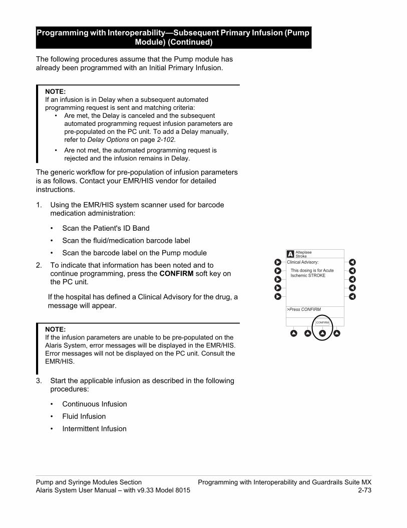
y Infusion (Pump
A
>Press CONFIRM
Clinical Advisory:
CONFIRM
AlteplaseStroke
This dosing is for AcuteIschemic STROKE
The following procedures assume that the Pump module has already been programmed with an Initial Primary Infusion.
The generic workflow for pre-population of infusion parameters is as follows. Contact your EMR/HIS vendor for detailed instructions.
1. Using the EMR/HIS system scanner used for barcode medication administration:
• Scan the Patient's ID Band
• Scan the fluid/medication barcode label
• Scan the barcode label on the Pump module
2. To indicate that information has been noted and to continue programming, press the CONFIRM soft key on the PC unit.
If the hospital has defined a Clinical Advisory for the drug, a message will appear.
3. Start the applicable infusion as described in the following procedures:
• Continuous Infusion
• Fluid Infusion
• Intermittent Infusion
Programming with Interoperability—Subsequent PrimarModule) (Continued)
NOTE:If an infusion is in Delay when a subsequent automated programming request is sent and matching criteria:
• Are met, the Delay is canceled and the subsequent automated programming request infusion parameters are pre-populated on the PC unit. To add a Delay manually, refer to Delay Options on page 2-102.
• Are not met, the automated programming request is rejected and the infusion remains in Delay.
NOTE:If the infusion parameters are unable to be pre-populated on the Alaris System, error messages will be displayed in the EMR/HIS. Error messages will not be displayed on the PC unit. Consult the EMR/HIS.
Pump and Syringe Modules Section Programming with Interoperability and Guardrails Suite MXAlaris System User Manual – with v9.33 Model 8015 2-73

y Infusion (Pump
ADRUG
AMOUNT
DILUENTVOLUME
100 mg
100 mL
[Conc]: 1 mg/mL
hour
mg/kg/h
>Press NEXT to Confirm
NEXT
TIMEUNITS
DOSINGUNITS
70 kgPATIENTWEIGHT
DRUGLIBRARY
AlteplaseStroke
AAA
RATE
VTBI
CONTINUOUS INFUSION
DOSE 0.81 mg/kg/h
[Conc]: 1 mg/mL
SETUP BOLUS
100 mL
STARTPAUSE
>Press START
56.7 mL/h
AlteplaseStroke
The following workflow assumes that the Pump module has already been programmed with an Initial Primary Continuous Infusion and that the Patient’s ID band, medication/fluid barcode label, and the module barcode labels have been scanned, see Programming with Interoperability—Initial Primary Infusion on page 2-62.
1. Review and verify that all parameters pre-populated on the Alaris System are correct prior to starting the infusion.
The drug amount, diluent volume, and patient weight (if continuous infusion is weight based) are pre-populated from the automated programming request.
2. Press NEXT to confirm.
3. After the parameters are confirmed, Press the START soft key.
The rate, VTBI and dose are pre-populated from the automated programming request.
Programming with Interoperability—Subsequent PrimarModule) (Continued)
Continuous Infusion
Programming with Interoperability and Guardrails Suite MX Pump and Syringe Modules Section 2-74 Alaris System User Manual – with v9.33 Model 8015

y Infusion (Pump
AYes
No
Infusion Setup
>Press Yes or No
New bag scan resultsin a recalculation of the rate to 45 mL/h
Accept rate change?
AAA
RATE
VTBI
CONTINUOUS INFUSION
DOSE 0.81 mg/kg/h
[Conc]: 1 mg/mL
SETUP BOLUS
100 mL
STARTPAUSE
>Press START
56.7 mL/h
AlteplaseStroke
If the subsequent automated programming request contains an infusion parameter (rate or dose) that changes the current infusion rate, a message appears with a recalculation of the rate notification.
4. From the Infusion Setup screen:
• Select YES to accept the rate change and start the infusion.
OR
• Select NO to return the infusion to its current infusion rate and change the VTBI to the volume to be infused contained in the automated programming request.
5. Review and verify that all parameters pre-populated on the Alaris System are correct prior to starting the infusion
6. Press the START soft key.
Programming with Interoperability—Subsequent PrimarModule) (Continued)
Continuous Infusion (Continued)
Pump and Syringe Modules Section Programming with Interoperability and Guardrails Suite MXAlaris System User Manual – with v9.33 Model 8015 2-75

y Infusion (Pump
0.45% Sodium Chloride
RATE
VTBI
>Press START
100 mL/h
_1000 mL
DELAYOPTIONS
SECOND-ARY START
APRIMARY INFUSION
VOLUMEDURATION
AYes
No
Infusion Setup
>Press Yes or No
New bag scan resultsin a recalculation of the rate to 45 mL/h
Accept rate change?
The following workflow assumes that the Pump module has already been programmed with an Initial Primary Fluid Infusion and that the Patient's ID band, medication/fluid barcode label, and the module barcode labels have been scanned, see Programming with Interoperability—Initial Primary Infusion on page 2-62.
1. Review and verify that all parameters pre-populated on the Alaris System are correct.
The rate and VTBI are pre-populated from the automated programming request. If the subsequent automated programming request contains an infusion parameter (rate) that changes the current infusion rate, a message appears with a recalculation of the rate notification.
2. Press the START soft key.
3. From the Infusion Setup screen:
• Select YES to accept the rate change and start the infusion.
OR
• Select NO to return the infusion its current infusion rate and change the VTBI to the volume to be infused contained in the automated programming request.
Programming with Interoperability—Subsequent PrimarModule) (Continued)
Fluid Infusion
Programming with Interoperability and Guardrails Suite MX Pump and Syringe Modules Section 2-76 Alaris System User Manual – with v9.33 Model 8015

y Infusion (Pump
0.45% Sodium Chloride
RATE
VTBI
>Press START
100 mL/h
_1000 mL
DELAYOPTIONS
SECOND-ARY START
APRIMARY INFUSION
VOLUMEDURATION
4. Review and verify that all parameters pre-populated on the Alaris System are correct.
5. Press the START soft key.
Programming with Interoperability—Subsequent PrimarModule) (Continued)
Fluid Infusion (Continued)
Pump and Syringe Modules Section Programming with Interoperability and Guardrails Suite MXAlaris System User Manual – with v9.33 Model 8015 2-77

y Infusion (Pump
ADRUG
AMOUNT
DILUENTVOLUME
10 mEq
50 mL
[Conc]:>Press NEXT to Confirm
NEXT
70 kgPATIENTWEIGHT
Potassium Chloride
0.2 mEq/kg
DOSE 0.143 mEq/kg
AAA
RATE=
VTBI
PRIMARY INFUSION
DURATION 1:00 hh:mm
[Conc]:
50 mL/h
SETUP
50
>Press START
Guardrails Drug SetupPotassium Chloride
START
mL
DOSE = 0.143 mEq/kg0.2 mEq/kg
RATEVOLUME
DELAYOPTIONS
The following workflow assumes that the Pump module has already been programmed with an Initial Primary Intermittent Infusion and that the Patient's ID band, medication/fluid barcode label, and the module barcode labels have been scanned, see Programming with Interoperability—Initial Primary Infusion on page 2-62.
1. Review and verify that all parameters pre-populated on the Alaris System are correct.
The drug amount, diluent volume, and patient weight (if intermittent infusion is weight based) or BSA (if intermittent infusion is BSA based) are pre-populated from the automated programming request.
2. Press NEXT to confirm.
3. Review and verify that all parameters pre-populated on the Alaris System are correct.
The rate, VTBI and duration are pre-populated from the automated programming request.
4. Press the START soft key.
Programming with Interoperability—Subsequent PrimarModule) (Continued)
Intermittent Infusion
Programming with Interoperability and Guardrails Suite MX Pump and Syringe Modules Section 2-78 Alaris System User Manual – with v9.33 Model 8015

y Infusion (Pump
0.45% Sodium Chloride
RATE
VTBI
>Press START
100 mL/h
_1000 mL
DELAYOPTIONS
SECOND-ARY START
APRIMARY INFUSION
VOLUMEDURATION
If the subsequent automated programming request contains an infusion parameter (rate or dose) that affects or changes the current infusion rate, a message appears with a recalculation of the rate notification.
5. From the Infusion Setup screen:
• Select YES to accept the rate change and start the infusion.
OR
• Select NO to return the infusion its current infusion rate and change the VTBI to the volume to be infused contained in the automated programming request.
6. Review and verify that all parameters pre-populated on the Alaris System are correct.
7. Press the START soft key.
Programming with Interoperability—Subsequent PrimarModule) (Continued)
Intermittent Infusion (Continued)
Pump and Syringe Modules Section Programming with Interoperability and Guardrails Suite MXAlaris System User Manual – with v9.33 Model 8015 2-79

mary Infusion ALARM INFUSE STANDBY
CHANNELSELECT
CHANNELOFF
PAUSE
RESTART
RATE (mL/h)
Hospital policy should determine the preferred method for programming subsequent infusions.
Subsequent infusion for the Syringe module refers to new syringes used with the Syringe module.
An automated programming request for a subsequent infusion can be sent to a Syringe module when it is infusing or in an idle state.
Pre-population of infusion parameters for a subsequent syringe is the same workflow as an Initial Primary Infusion., see Programming with Interoperability—Initial Primary Infusion on page 2-62.
Programming with Interoperability—Subsequent Pri(Syringe Module)
NOTE:If an infusion is in Delay when a subsequent automated programming request is sent, the Delay will be canceled and the subsequent automated programming request infusion parameters will be pre-populated on the PC unit. To add a delay manually, see Delay Options on page 2-102
Programming with Interoperability and Guardrails Suite MX Pump and Syringe Modules Section 2-80 Alaris System User Manual – with v9.33 Model 8015

(Pump Module)
Secondary applications require the use of a check valve or clamp on the primary IV line in order to prevent backflow of secondary medication into the primary line.
WARNING
The secondary administration set must be primed prior to beginning the secondary infusion.
WARNING
This mode is designed to support programming of secondary infusions ("piggybacking") on the same module as a primary fluid. When the secondary VTBI reaches zero, an audio tone sounds (if enabled) indicating completion of the secondary infusion. The primary infusion resumes automatically.
When the instrument is programmed and delivering in the secondary mode, the primary infusion is temporarily stopped and fluid is drawn from the secondary container. Delivery from the primary container resumes when the fluid level in the secondary line is level with the fluid in the primary container.
In order to pre-populate infusion parameters for a secondary infusion, a primary fluid that supports a secondary must already be programmed or infusing. For more information, see Programming with Interoperability—Initial Primary Infusion—Fluids page 2-69 and Manual Programming—Primary Infusion—IV Fluid Infusion page 2-45.
1. Open a secondary administration set package, remove set, and close clamp.
2. Insert the administration set spike into the prepared fluid container and hang the secondary container, following accepted hospital/facility procedure.
3. Fill drip chamber to 2/3 full.
4. Open the secondary administration set clamp and prime the set. Close clamp.
5. Attach the secondary administration set to the upper injection site on primary set.
Programming with Interoperability—Secondary Infusion
Infusion
Setup
NOTE:When primary sets without a check valve are used, the clinician must manually clamp off the primary line during the secondary infusion and then manually unclamp the line once the secondary VTBI reaches zero.
Pump and Syringe Modules Section Programming with Interoperability and Guardrails Suite MXAlaris System User Manual – with v9.33 Model 8015 2-81

(Pump Module)
Secondary ContainerBottle
at least 9½"
The secondary solution container must be higher than the primary solution container.
WARNING
6. Using the hanger provided with secondary administration set, lower the primary fluid container to the height indicated in following illustrations.
Programming with Interoperability—Secondary Infusion(Continued)
Infusion (Continued)
Setup (Continued)
Hanger
Primary Container
Secondary ContainerBag
Primary Container
at least 9½"
Programming with Interoperability and Guardrails Suite MX Pump and Syringe Modules Section 2-82 Alaris System User Manual – with v9.33 Model 8015

(Pump Module)
The generic workflow for pre-population of infusion parameters is as follows. Contact your EMR/HIS vendor for detailed instructions. Using the EMR/HIS system scanner used for barcode medication administration
• Scan Patient's ID Band
• Scan fluid/medication barcode label
• Scan barcode label on the Pump module
7. Press the SECONDARY soft key to continue with the pre-population of the infusion parameters for the secondary infusion.
The set-up page for the secondary infusion appears with the drug amount, diluent volume, and patient weight (if intermittent infusion is weight based) or BSA (if intermittent infusion is BSA based) pre-populated from the automated programming request.
8. Review and verify that all parameters pre-populated on the Alaris System are correct.
9. Press NEXT to confirm.
Programming with Interoperability—Secondary Infusion(Continued)
Infusion (Continued)
Infusion
NOTE:If the infusion parameters are unable to be pre-populated on the Alaris System, error messages are displayed in the EMR/HIS. Error messages are not displayed on the PC unit. Consult the EMR/HIS.
Pump and Syringe Modules Section Programming with Interoperability and Guardrails Suite MXAlaris System User Manual – with v9.33 Model 8015 2-83

(Pump Module)
The clamp on the secondary administration set must be opened. If the clamp is not opened, the fluid is delivered from the primary container.
WARNING
10. Review and verify that all parameters pre-populated on the Alaris System are correct prior to starting the infusion.
The rate, VTBI, and duration are pre-populated from the automated programming request.
11. Open the clamp on secondary administration set.
12. Press the START soft key.
13. Verify that drops are flowing from the secondary container drip chamber.
Programming with Interoperability—Secondary Infusion(Continued)
Infusion (Continued)
The secondary VTBI settings require consideration of such variables as factory overfill and medication additions.Underestimating the volume causes the remaining secondary solution to be infused at the primary rate; overestimating results in the primary solution being infused at the secondary rate. Multiple doses from a single container are not possible.
WARNING
NOTE:Pre-population of infusion parameters on the Alaris System DOES NOT automatically start the infusion. As with any infusion, all infusion parameters need to be reviewed and confirmed by the clinician before pressing START.
Programming with Interoperability and Guardrails Suite MX Pump and Syringe Modules Section 2-84 Alaris System User Manual – with v9.33 Model 8015

(Pump Module)
1. Press CHANNEL SELECT key.
2. Press SET UP soft key.
3. Press PRIMARY soft key.
4. To change primary infusion parameter, press applicable soft key (RATE or VTBI) and use numeric data entry keys.
5. Verify correct primary infusion parameters and press SECONDARY soft key.
Secondary setup screen is displayed.
6. Press NEXT soft key.
7. To resume secondary infusion, press START soft key.
8. Verify that drops are flowing from the secondary container drip chamber.
Programming with Interoperability—Secondary Infusion(Continued)
Change Primary Infusion Parameter
Pump and Syringe Modules Section Programming with Interoperability and Guardrails Suite MXAlaris System User Manual – with v9.33 Model 8015 2-85

(Pump Module)
1. Press the CHANNEL SELECT key.
2. Press the SETUP soft key.
3. Press the PRIMARY soft key.
4. Close the clamp on the secondary administration set.
-or-
Disconnect the secondary administration set from the upper injection port.
5. Press the START soft key.
6. To stop the secondary infusion and begin infusing the primary, press the Yes soft key.
The secondary infusion stops and primary infusion begins. The main screen appears.
Programming with Interoperability—Secondary Infusion(Continued)
Stop Secondary and Return to Primary
NOTE:The SEC to PRI alert does not sound when the infusion is manually ended and returned to the primary.
Programming with Interoperability and Guardrails Suite MX Pump and Syringe Modules Section 2-86 Alaris System User Manual – with v9.33 Model 8015

Suite MX Protection
The following procedures should be used only when the drug to be infused is not listed in the Drug Library. When programming a drug not listed in the Drug Library, the drug calculation must be programmed using the DRUG CALC soft key within the Drug Library. There are no limits associated with any non-library drug calculation.
The illustrations in this procedure assume:
• ALL Mode (Syringe module), Drug Calculation, Dynamic Pressure Display, Profiles, and Volume Duration configurable settings are enabled.
• NEOI (Syringe module) and Delay Options configurable settings are disabled.
Programming—NO Guardrails
Pump and Syringe Modules Section Programming—NO Guardrails Suite MX ProtectionAlaris System User Manual – with v9.33 Model 8015 2-87

rotection
ALARM INFUSE STANDBY
CHANNELSELECT
CHANNELOFF
PAUSE
RESTART
RATE (mL/h)
CHANNELSELECT
CHANNELOFF
RESTART
PAUSE
ALARM INFUSE STANDBY
RATE (mL/h)
When addressing or clearing an occlusion:
Ensure that the fluid flow to the patient is OFF to prevent administering an unintended bolus. An occlusion may pressurize the infusion tubing and syringe, which can result in an unintended bolus of drug when the occlusion is cleared. In order to prevent this additional bolus, disconnect the tubing or relieve the excess pressure through a stopcock, if present. The clinician should weigh the relative risks of disconnection with the risks of an unintended bolus of drug.
* Using a set with a pressure sensing
WARNING
If Delay Options is enabled, the PAUSE soft key becomes DELAY OPTIONS.
1. (see PC unit section of this User Manual, "General Setup and Operation," "Start-Up"):
a. Power on system.
b. Choose Yes or No to New Patient?
c. Confirm current Profile or select a new Profile.
d. Enter patient identifier, if required.
2. Prepare and load syringe/administration set (see "Getting Started").
3. Prime (see "Getting Started").
4. Start applicable infusion, as described in following procedures:
Basic Infusion without Drug CalculationBasic Infusion with Drug CalculationBolus Dose
The following procedure should be used only to set up a Basic Infusion. To program an infusion using Guardrails Drugs, see "Primary Infusion - With Guardrails Suite MX Protection."
1. Press CHANNEL SELECT key.
2. Press Basic Infusion soft key.
Infusion Setup screen appears.
3. Start applicable infusion, as described in following procedures (see "Primary Infusion - With Guardrails Suite MX Protection," "IV Fluid Infusion" procedure).
Rate/Volume InfusionVolume/Duration Infusion
Manual Programming—NO Guardrails Suite MX P
Basic Infusion without Drug Calculation
Programming—NO Guardrails Suite MX Protection Pump and Syringe Modules Section 2-88 Alaris System User Manual – with v9.33 Model 8015

tion (Continued)
ALARM INFUSE STANDBY
CHANNELSELECT
CHANNELOFF
PAUSE
RESTART
RATE (mL/h)
CHANNELSELECT
CHANNELOFF
RESTART
PAUSE
ALARM INFUSE STANDBY
RATE (mL/h)
SILENCE
OPTIONS
147
CLEAR
2580
369 ENTER
CANCEL
SYSTEMON
EXIT
A
PAGEDOWN
A
>Select Drug
Acyclovir
Amphoterocin B
Carboplatin
Cyclophosphamide
K-O
F-J
P-T
U-Z
A-E
Guardrails DrugsAdult ICU
Aminophylline
DRUGCALC
1. Press CHANNEL SELECT key on module running infusion to be promoted.
2. Press OPTIONS key.
3. Press Guardrails Drugs soft key.
4. Continue programming (see "Primary Infusion - With Guardrails Suite MX Protection").
1. Press Guardrails Drugs soft key.
2. Press DRUG CALC soft key.
3. To enter DRUG AMOUNT, use numeric data entry keys.
4. Press soft key for appropriate unit of measure for drug amount.
Manual Programming—NO Guardrails Suite MX Protec
Promote Basic Infusion to Guardrails Software Protection Infusion
Basic Infusion with Drug Calculation
NOTE:Basic infusions can only be promoted to Guardrails Continuous Infusion or Guardrails IV Fluids. A Basic Infusion cannot be promoted to a Guardrails intermittent drug.
Pump and Syringe Modules Section Programming—NO Guardrails Suite MX ProtectionAlaris System User Manual – with v9.33 Model 8015 2-89

tion (Continued)
ALARM INFUSE STANDBY
CHANNELSELECT
CHANNELOFF
PAUSE
RESTART
RATE (mL/h)
CHANNELSELECT
CHANNELOFF
RESTART
PAUSE
ALARM INFUSE STANDBY
RATE (mL/h)
5. To enter diluent volume, use numeric data entry keys.
6. Press PATIENT WEIGHT soft key.
7. To indicate whether or not patient weight is to be used in Drug Calculation, press either Yes or No soft key.
8. To enter patient weight (if required) in kilograms, use numeric data entry keys.
9. Press TIME UNITS soft key.
10. To select time base for drug calculation, press either Min, Hour, or Day soft key.
11. Press soft key next to desired DOSING UNITS.
12. Verify correct infusion parameters and press NEXT soft key.
Syringe module: If ALL Mode is enabled, VTBI ALL is displayed.
13. To make a rate or dose entry, press applicable soft key, RATE or DOSE, and use numeric data entry keys (other value is calculated and displayed).
14. To enter volume to be infused, press VTBI soft key and use numeric data entry keys.
Manual Programming—NO Guardrails Suite MX Protec
Basic Infusion with Drug Calculation (Continued)
ALARM INFUSE STANDBY
CHANNELSELECT
CHANNELOFF
PAUSE
RESTART
RATE (mL/h)
Programming—NO Guardrails Suite MX Protection Pump and Syringe Modules Section 2-90 Alaris System User Manual – with v9.33 Model 8015

tion (Continued)
ALARM INFUSE STANDBY
CHANNELSELECT
CHANNELOFF
PAUSE
RESTART
RATE (mL/h)
CHANNELSELECT
CHANNELOFF
RESTART
PAUSE
ALARM INFUSE STANDBY
RATE (mL/h)
AAA
RATE
>Press START
VTBI
CONTINUOUS INFUSION
DOSE 5 mcg/kg/min
[Conc]: 5000 mcg/mL
4.2 mL/h
SETUP BOLUS STARTPAUSE
Drug Calculation
50 mL
• Pump module:
◦ When VTBI is less than 10 mL, entry can be to two decimal places (one-hundredth of a mL).
◦ In Drug Calculation mode, system infuses at calculated rate rounded to nearest one-hundredth of a mL per hour (as displayed on programming screen). Rate shown in Rate Display is rounded to nearest one-tenth of a mL per hour.
• Syringe module:
◦ If ALL Mode is enabled for syringe configuration in Data Set, ALL is displayed in VTBI field and estimated available volume in syringe is displayed.
OR
If ALL Mode is disabled for syringe configuration in Data Set, estimated available volume in syringe is displayed when VTBI soft key is pressed.
◦ To enter or change a numeric VTBI value, press VTBI soft key and use numeric data entry keys.
◦ To deliver entire contents of syringe: Keep an ALL VTBI value, or press ALL soft key to change a numeric VTBI value to ALL.
• BOLUS soft key appears only if Bolus Dose is enabled within selected Profile, drug is bolusable, and a VTBI is entered.
15. Verify correct parameters and press START soft key.
Manual Programming—NO Guardrails Suite MX Protec
Basic Infusion with Drug Calculation (Continued)
CHANNELSELECT
CHANNELOFF
RESTART
PAUSE
ALARM INFUSE STANDBY
RATE (mL/h)
ALARM INFUSE STANDBY
CHANNELSELECT
CHANNELOFF
PAUSE
RESTART
RATE (mL/h)
Pump and Syringe Modules Section Programming—NO Guardrails Suite MX ProtectionAlaris System User Manual – with v9.33 Model 8015 2-91

tion (Continued)
ALARM INFUSE STANDBY
CHANNELSELECT
CHANNELOFF
PAUSE
RESTART
RATE (mL/h)
CHANNELSELECT
CHANNELOFF
RESTART
PAUSE
ALARM INFUSE STANDBY
RATE (mL/h)
AAA
DOSE
PATIENTWEIGHT
BOLUS DOSE
Drug Calculation
_ 2000
DURATION
[Conc]: 5000 mcg/mL
SETUP
>Select the Desired DosingUnits
CONT-INUOUS
16. Syringe module:
• Unclamp tubing and attach administration set to patient.
• Unclamping tubing and starting infusion before attaching administration set to patient minimizes any potential bolus that can be released from pressure built up in set due to normal syringe loading and priming.
1. Set up infusion as described in "Continuous Infusion - Drug Calculation" procedure, but do not start infusion.
2. Press BOLUS soft key.
3. To enter Bolus Dose, use numeric data entry keys.
• After a Bolus Dose and weight (if used) are entered, bolus VTBI and concentration [conc] alternate in Main Display.
4. Press soft key next to appropriate unit of measure for dose.
If mcg or mg is selected as dosing unit, a PATIENT WEIGHT entry cannot be made. If mcg/kg or mg/kg is selected as dosing unit, a PATIENT WEIGHT entry is required.
5. To enter bolus duration, use numeric data entry keys.
TOTAL DOSE alternates with INFUSE AT rate.
Manual Programming—NO Guardrails Suite MX Protec
Basic Infusion with Drug Calculation (Continued)
Bolus Dose
ALARM INFUSE STANDBY
CHANNELSELECT
CHANNELOFF
PAUSE
RESTART
RATE (mL/h)
NOTE:Do not enter a patient weight if weight is not used in the calculation.
Programming—NO Guardrails Suite MX Protection Pump and Syringe Modules Section 2-92 Alaris System User Manual – with v9.33 Model 8015

tion (Continued)
ALARM INFUSE STANDBY
CHANNELSELECT
CHANNELOFF
PAUSE
RESTART
RATE (mL/h)
CHANNELSELECT
CHANNELOFF
RESTART
PAUSE
ALARM INFUSE STANDBY
RATE (mL/h)
6. Verify correct parameters and press START soft key.
To see details during bolus infusion, press CHANNEL SELECT key.
7. Syringe module:
• If Bolus Dose was programmed at beginning of infusion, unclamp tubing and attach administration set to patient.
• Unclamping tubing and starting infusion before attaching administration set to patient minimizes any potential bolus that can be released from pressure built up in set due to normal syringe loading and priming.
See "Primary Infusion - With Guardrails Suite MX Protection," "Bolus Dose" procedure.
Manual Programming—NO Guardrails Suite MX Protec
Bolus Dose (Continued)
Stop and Restore Bolus Dose
ALARM INFUSE STANDBY
CHANNELSELECT
CHANNELOFF
PAUSE
RESTART
RATE (mL/h)
Pump and Syringe Modules Section Programming—NO Guardrails Suite MX ProtectionAlaris System User Manual – with v9.33 Model 8015 2-93

tion (Continued)CHANNELSELECT
CHANNELOFF
RESTART
PAUSE
ALARM INFUSE STANDBY
RATE (mL/h)
See Manual Programming—Secondary Infusion (Pump Module) on page 2-51 for a description of the secondary infusion mode and for setup instructions.
The following procedure should be used only when:
• drug to be infused is not listed in Drug Library,
• primary infusion is running, and
• a check valve administration set is being used.
To program a primary infusion, see Manual Programming—Primary Infusion on page 2-24. To program a basic infusion, see Basic Infusion without Drug Calculation on page 2-88.
1. Press SECONDARY soft key and then BASIC SEC soft key.
Manual Programming—NO Guardrails Suite MX Protec
Secondary Infusion
Infusion
Programming—NO Guardrails Suite MX Protection Pump and Syringe Modules Section 2-94 Alaris System User Manual – with v9.33 Model 8015

tion (Continued)CHANNELSELECT
CHANNELOFF
RESTART
PAUSE
ALARM INFUSE STANDBY
RATE (mL/h)
2. Enter secondary infusion rate or duration, as follows:
• To enter secondary infusion rate, press RATE soft key and use numeric data entry keys.
• To enter duration, press DURATION soft key and use numeric data entry keys.
3. To enter secondary volume to be infused, press VTBI soft key and use numeric data entry keys.
4. Open clamp on secondary administration set.
5. Verify correct infusion parameters and press START soft key.
6. Verify that drops are flowing from the secondary container drip chamber.
1. Press CHANNEL SELECT key.
2. Press PRIMARY soft key.
3. To change primary infusion parameter, press applicable soft key (RATE or VTBI) and use numeric data entry keys.
4. Verify correct primary infusion parameters and press SECONDARY soft key.
Secondary setup screen is displayed.
5. To resume secondary infusion, press START soft key.
6. Verify that drops are flowing from the secondary container drip chamber.
See Manual Programming—Secondary Infusion (Pump Module) on page 2-51.
Manual Programming—NO Guardrails Suite MX Protec
Infusion (Continued)
Change Primary Infusion Parameter
Stop Secondary and Return to Primary
Pump and Syringe Modules Section Programming—NO Guardrails Suite MX ProtectionAlaris System User Manual – with v9.33 Model 8015 2-95

General Programming
ALARM INFUSE STANDBY
CHANNELSELECT
CHANNELOFF
PAUSE
RESTART
RATE (mL/h)
CHANNELSELECT
CHANNELOFF
RESTART
PAUSE
ALARM INFUSE STANDBY
RATE (mL/h)
CHANNELSELECT
CHANNELOFF
RESTART
PAUSE
1. Press PAUSE key.
• PAUSE scrolls in Message Display.
• PAUSED appears on Main Display.
• Yellow Standby Status Indicator illuminates.
• After 2 minutes, PAUSE-RESTART CHANNEL visual and audio prompts begin, and yellow Standby Status Indicator flashes.
Pause, Change, Restart Infusion
Pause and Restart Infusion
General Programming Pump and Syringe Modules Section 2-96 Alaris System User Manual – with v9.33 Model 8015

ed)
ALARM INFUSE STANDBY
CHANNELSELECT
CHANNELOFF
PAUSE
RESTART
RATE (mL/h)
CHANNELSELECT
CHANNELOFF
RESTART
PAUSE
ALARM INFUSE STANDBY
RATE (mL/h)
OR
CHANNELSELECT
CHANNELOFF
RESTART
PAUSE
2. To reinitiate infusion:
Press RESTART key.
OR
Press CHANNEL SELECT key and then press START soft key.
1. Press CHANNEL SELECT key.
2. Press either RATE or VTBI soft key.
3. To enter desired parameter, use up/down arrows for rate titration, or numeric data entry keys.
4. Verify correct infusion parameter entry and press START soft key.
1. To restart infusion using stored parameters, press RESTORE soft key.
2. Verify correct parameters and press START soft key.
Pause, Change, Restart Infusion (Continu
Pause and Restart Infusion (Continued)
Change Rate or VTBI During Infusion
Restore Infusion
NOTES: To stop a Bolus Dose, see the "Bolus Dose" procedure. The Pump module keypad is used in the illustrations but the
keys are the same for the Syringe module. An infusion can also be paused by pressing the PAUSE
soft key (on PC unit), if the Delay Options are disabled. To pause an infusion programmed with Delay Options enabled, see "Delay Options," "Pause Infusion."
NOTE: To restore a Bolus Dose, see the "Bolus Dose" procedure. The restore option is only available if the system is powered up
within 8 hours of the last use and when the prompt for New Patient? is selected as No.
Pump and Syringe Modules Section General ProgrammingAlaris System User Manual – with v9.33 Model 8015 2-97

ALARM INFUSE STANDBY
CHANNELSELECT
CHANNELOFF
PAUSE
RESTART
RATE (mL/h)
CHANNELSELECT
CHANNELOFF
RESTART
PAUSE
ALARM INFUSE STANDBY
RATE (mL/h)
VTBI = 497.0 mL
VTBI = 57.0 mL
VTBI = 249.0 mL
PAUSED
VOLUMEINFUSED
AUDIOADJUST
Midtown HospitalAdult ICU
VTBI = 497.0 mL
VTBI = 57.0 mL
VTBI = 249.0 mL
PAUSED
VOLUMEINFUSED
AUDIOADJUST
Midtown HospitalAdult ICU
Volume Infused
TOTAL VOLUME (mL)LAST
CLEARED
>Select Channels to Clearor Press CLEAR ALL
PRI/SECVOLUME
CLEARALL
MAINSCREEN
401.1
42.5
478.1
789.1
08:00
08:00
2002-03-10
2002-03-10
2002-03-11
2002-03-10
07:30
12:00
A
B
CLEARALL
MAINSCREEN
42.5
48.1
Volume Infused
>Select Channels to Clearor Press CLEAR ALL
TOTAL VOLUME (mL)LAST
CLEARED
07:302002-3-11
08:002002-3-10
1. To view volume infused, press VOLUME INFUSED soft key.
• Total volume infused (primary + secondary), and time and date volume infused was last cleared, display for each module.
2. Pump module: To view primary and secondary volume(s) infused, press PRI/SEC VOLUME soft key.
3. To clear volume infused:
• If only selected module is to be cleared, press soft key next to applicable module and press CLEAR CHANNEL soft key.
Volume clears on selected module.
• If all modules are to be cleared, press CLEAR ALL soft key.
View and Clear Volume Infused
CHANNELSELECT
CHANNELOFF
RESTART
PAUSE
ALARM INFUSE STANDBY
RATE (mL/h)
General Programming Pump and Syringe Modules Section 2-98 Alaris System User Manual – with v9.33 Model 8015

d)
ALARM INFUSE STANDBY
CHANNELSELECT
CHANNELOFF
PAUSE
RESTART
RATE (mL/h)
CHANNELSELECT
CHANNELOFF
RESTART
PAUSE
ALARM INFUSE STANDBY
RATE (mL/h)
Volume Infused
>Select Channels to Clearor Press CLEAR ALL
CLEARALL
MAINSCREEN
PRI (mL) SEC (mL)
0.0
0.0
0.0
0.0
0.0
0.0
0.0
0.0
PRI/SECVOLUME
Volume Infused
>Select Channels to Clearor Press CLEAR ALL
CLEARALL
MAINSCREEN
PRI (mL) SEC (mL)
0.0
0.0
0.0
0.0
0.0
0.0
0.0
0.0
PRI/SECVOLUME
ALARM INFUSE STANDBY
CHANNELSELECT
CHANNELOFF
PAUSE
RESTART
RATE (mL/h)
CHANNELSELECT
CHANNELOFF
RESTART
PAUSE
ALARM INFUSE STANDBY
RATE (mL/h)
• To return to main screen, press MAIN SCREEN soft
key.
The Channel Labels option is not available if a Guardrails IV fluids or Guardrails drugs infusion is running on the module. A channel label is removed when the Basic Infusion is promoted to a Guardrails IV fluids or Guardrails Drugs infusion.
1. Press CHANNEL SELECT key.
2. Press OPTIONS key.
View and Clear Volume Infused (Continue
Channel Labels
Select
NOTES: Date format is year-month-day. Pump module: A PRI/SEC VOLUME soft key is available to
allow secondary volume infused to be displayed. If no key is pressed, main screen appears after 30 seconds. The illustrated example is a Syringe module display. A Pump
module display has a PRI/SEC VOLUME soft key
Pump and Syringe Modules Section General ProgrammingAlaris System User Manual – with v9.33 Model 8015 2-99

ALARM INFUSE STANDBY
CHANNELSELECT
CHANNELOFF
PAUSE
RESTART
RATE (mL/h)
CHANNELSELECT
CHANNELOFF
RESTART
PAUSE
ALARM INFUSE STANDBY
RATE (mL/h)
Channel Options 1 of 2A
>Select an Option or EXI T
EXIT PAGEDOWN
Guardrails Drugs
Pressure Limit - High
Multidose
Prime Set with Syringe
Guardrails IV Fluids
Channel Options
Guardrails Drugs
Pressure Limit - P
Channel Labels
A
>Select an Option or EXIT
EXIT
Multidose
Guardrails IV Fluids
Channel Options 2 of 2A
>Select an Option or EXIT
EXITPAGEUP
Channel LabelsALARM INFUSE STANDBY
CHANNELSELECT
CHANNELOFF
PAUSE
RESTART
RATE (mL/h)
CHANNELSELECT
CHANNELOFF
RESTART
PAUSE
ALARM INFUSE STANDBY
RATE (mL/h)
3. Syringe module: Press PAGE DOWN soft key.
4. Press Channel Labels soft key.
Channel Labels (Continued)
Select (Continued)
ALARM INFUSE STANDBY
CHANNELSELECT
CHANNELOFF
PAUSE
RESTART
RATE (mL/h)
General Programming Pump and Syringe Modules Section 2-100 Alaris System User Manual – with v9.33 Model 8015

ALARM INFUSE STANDBY
CHANNELSELECT
CHANNELOFF
PAUSE
RESTART
RATE (mL/h)
CHANNELSELECT
CHANNELOFF
RESTART
PAUSE
ALARM INFUSE STANDBY
RATE (mL/h)
A
>Select Channel Label
PAGEDOWN
F-J
K-O
P-T
U-Z
A-E
EXIT
Channel Label DisplayNICU
Broviac
PICC
UAC
UVC
White Port
5. Press soft key for desired label.
• Selected label is highlighted and scrolls in Message Display.
6. To continue infusion, press START soft key.OR
Program infusion as previously described.
1. Press CHANNEL SELECT key.
2. Press OPTIONS key.
3. Syringe module: Press PAGE DOWN soft key.
4. Press Channel Labels soft key.
Channel Labels (Continued)
Select (Continued)
Remove
NOTE: To view additional labels, press a soft key next to a letter group
to navigate through the alphabet, and/or PAGE UP and PAGE DOWN soft keys.
ALARM INFUSE STANDBY
CHANNELSELECT
CHANNELOFF
PAUSE
RESTART
RATE (mL/h)
Pump and Syringe Modules Section General ProgrammingAlaris System User Manual – with v9.33 Model 8015 2-101

ALARM INFUSE STANDBY
CHANNELSELECT
CHANNELOFF
PAUSE
RESTART
RATE (mL/h)
CHANNELSELECT
CHANNELOFF
RESTART
PAUSE
ALARM INFUSE STANDBY
RATE (mL/h)
A
>Select Channel Label
PAGEDOWN
EXIT
Channel Label DisplayNICU
CLEARLABEL
F-J
K-O
P-T
U-Z
A-EBroviac
PICC
UAC
UVC
White Port
ALARM INFUSE STANDBY
CHANNELSELECT
CHANNELOFF
PAUSE
RESTART
RATE (mL/h)
CHANNELSELECT
CHANNELOFF
RESTART
PAUSE
ALARM INFUSE STANDBY
RATE (mL/h)
ALARM INFUSE STANDBY
CHANNELSELECT
CHANNELOFF
PAUSE
RESTART
RATE (mL/h)
CHANNELSELECT
CHANNELOFF
RESTART
PAUSE
ALARM INFUSE STANDBY
RATE (mL/h)
5. Press CLEAR LABEL soft key.
Label stops scrolling in Message Display.
6. To begin infusion, press START soft key.OR
Program infusion as previously described.
See the PC unit section of this User Manual.
Delay Options can be enabled at the time the Alaris System is configured for use. If Delay Options is enabled, a primary infusion can be programmed to be delayed for a specified period of time and a callback can be scheduled, as described in the following procedures.
Since by definition, an infusion with Delay Options infuses for a programmed period of time, it is assumed that another infusing IV line keeps the vein open until the delayed infusion begins. When a delay is programmed, the infusion stops when complete and no KVO is delivered.
Channel Labels (Continued)
Remove (Continued)
Anesthesia Mode
Delay Options
General Programming Pump and Syringe Modules Section 2-102 Alaris System User Manual – with v9.33 Model 8015

ALARM INFUSE STANDBY
CHANNELSELECT
CHANNELOFF
PAUSE
RESTART
RATE (mL/h)
CHANNELSELECT
CHANNELOFF
RESTART
PAUSE
ALARM INFUSE STANDBY
RATE (mL/h)
>Press START
_40 mL/h
A IVAC 50 mL
RATE
VTBI
VOLUMEDURATION STARTDELAY
OPTIONS
ALL
>Press START
40 mL/h
A
250 mL
Infusion Setup
RATE
SECOND-ARY
STARTDELAYOPTIONS
VTBI
ALARM INFUSE STANDBY
CHANNELSELECT
CHANNELOFF
PAUSE
RESTART
RATE (mL/h)
CHANNELSELECT
CHANNELOFF
RESTART
PAUSE
ALARM INFUSE STANDBY
RATE (mL/h)
The delay period for an infusion can be programmed as a specific number of minutes or a time of day, as described in the following procedures. An infusion delay can be programmed prior to or after an infusion is initiated.
The Delay for option is used to program an infusion delay for a minimum of 1 minute and up to 120 minutes.
1. Press DELAY OPTIONS soft key.
Delay Options (Continued)
Delay Infusion
Specify by Minutes
Pump and Syringe Modules Section General ProgrammingAlaris System User Manual – with v9.33 Model 8015 2-103

ALARM INFUSE STANDBY
CHANNELSELECT
CHANNELOFF
PAUSE
RESTART
RATE (mL/h)
CHANNELSELECT
CHANNELOFF
RESTART
PAUSE
ALARM INFUSE STANDBY
RATE (mL/h)
A Delay Options 08:00
CALLBACK
Pause
CONFIRMEXIT
>Select a Delay Option
Delay for
Delay until
A Delay Options 08:00
CALLBACK
Pause
CONFIRMEXIT
>Select a Delay Option
Delay for
Delay until
2. Press Delay for soft key.
3. To enter number of minutes (up to 120) infusion is to be delayed for, use numeric data entry keys.
4. Press CONFIRM soft key.
• Delay period counts down on Main Display.
• If a Before callback has not been scheduled (see "Schedule a Callback" procedure), infusion automatically initiates at end of delay period.
The Delay until option is used to program an infusion delay for a minimum of 1 minute and up to 23 hours 59 minutes.
1. Press DELAY OPTIONS soft key.
2. Press Delay until soft key.
Delay Options (Continued)
Delay Infusion (Continued)
Specify by Minutes (Continued)
Specify by Time of Day
General Programming Pump and Syringe Modules Section 2-104 Alaris System User Manual – with v9.33 Model 8015

ALARM INFUSE STANDBY
CHANNELSELECT
CHANNELOFF
PAUSE
RESTART
RATE (mL/h)
CHANNELSELECT
CHANNELOFF
RESTART
PAUSE
ALARM INFUSE STANDBY
RATE (mL/h)
Delayed OptionsA
Time of Day
ChangeTime
Current time:08:00
CONFIRM
>CONFIRM Time-of-Day
EXIT
3. If Current time displayed is correct, press CONFIRM soft key; otherwise, press Change Time and enter correct time. (See "System Options," "Time of Day" in PC unit section of this User Manual.)
4. To enter time of day infusion is to be initiated (up to 23 hours 59 minutes), use numeric data entry key.
5. Press CONFIRM soft key.
• Time infusion is scheduled to start appears on Main Display.
• • If a Before callback has not been scheduled (see "Schedule a Callback" procedure), infusion automatically initiates at end of delay period.
Delay Options (Continued)
Delay Infusion (Continued)
Specify by Time of Day (Continued)
NOTE: If the current time has been previously confirmed, the TIME OF
DAY screen does not display. If a delay is canceled before the delay ends, the Alaris System
will alarm when the VTBI reaches zero and then changes to KVO rate.
Pump and Syringe Modules Section General ProgrammingAlaris System User Manual – with v9.33 Model 8015 2-105

ALARM INFUSE STANDBY
CHANNELSELECT
CHANNELOFF
PAUSE
RESTART
RATE (mL/h)
CHANNELSELECT
CHANNELOFF
RESTART
PAUSE
ALARM INFUSE STANDBY
RATE (mL/h)
A
Pause
Delay for
CONFIRM
Delay Options 08:00
CALLBACK
Delay until 09:00
> > > > > >
>Select a Callback Option
After
BeforeAnd After
None
Before
EXIT
When programming a Delay for or Delay until infusion, a callback can be scheduled for that infusion. There are three types of callback:
• Before—gives an alert when delay period is completed and infusion needs to be initiated.
• After—gives an alert when delayed infusion has completed.
• Before and After—gives an alert when delay period is completed and infusion needs to be initiated and when delayed infusion has completed.
The default callback (After), or the callback for the current Profile, appears on the Main Display. To schedule a different callback:
1. Prior to pressing CONFIRM soft key to initiate delay during Delay for or Delay until programming process, press CALL BACK soft key.
2. Press soft key corresponding to desired callback option.
Scheduled callback appears on Main Display.
3. To initiate delay, press CONFIRM soft key.
• If Delay until programming, time infusion is scheduled to start appears on Main Display.
ORIf Delay for programming, delay period counts down on Main Display.
• If Before option was selected:
◦ An audio prompt sounds when delay period has ended.
◦ Yellow Standby Status Indicator flashes.
◦ DELAY COMPLETE scrolls in Message Display and appears on Main Display.
Delay Options (Continued)
Schedule a Callback
General Programming Pump and Syringe Modules Section 2-106 Alaris System User Manual – with v9.33 Model 8015

ALARM INFUSE STANDBY
CHANNELSELECT
CHANNELOFF
PAUSE
RESTART
RATE (mL/h)
CHANNELSELECT
CHANNELOFF
RESTART
PAUSE
ALARM INFUSE STANDBY
RATE (mL/h)
A Delay Options 09:30
CALLBACK
CONFIRM
>Select a Delay Option
Delay for
Delay until
Pause
EXIT
• If After option was selected:
◦ An audio prompt sounds when delayed infusion completes, and continues to sound until responded to.
◦ Yellow Standby Status Indicator flashes until audio is silenced.
◦ Infusion completed message appears on Main Display.
◦ Infusion Complete scrolls in Message Display.
• If Before and After option was selected, same prompts and indicators mentioned above for both Before and After options are exhibited.
4. To respond to a callback:
• Before callback:
Press CHANNEL SELECT key and then START soft key.
ORPress RESTART key.
• After callback: Press CONFIRM soft key.
• Before and After callback: Respond as indicated above for both Before and After.
1. Press DELAY OPTIONS soft key.
2. Press Pause soft key.
• If an alert has occurred, pause is not initiated by system until alert is addressed.
Delay Options (Continued)
Schedule a Callback (Continued)
Pause Infusion
Pump and Syringe Modules Section General ProgrammingAlaris System User Manual – with v9.33 Model 8015 2-107

ALARM INFUSE STANDBY
CHANNELSELECT
CHANNELOFF
PAUSE
RESTART
RATE (mL/h)
CHANNELSELECT
CHANNELOFF
RESTART
PAUSE
ALARM INFUSE STANDBY
RATE (mL/h)
ALARM INFUSE STANDBY
CHANNELSELECT
CHANNELOFF
PAUSE
RESTART
RATE (mL/h)
CHANNELSELECT
CHANNELOFF
RESTART
PAUSE
ALARM INFUSE STANDBY
RATE (mL/h)
• The Multidose feature is to be used only by personnel properly trained in using multidose infusions.
• Caution labels, which clearly differentiate single dose and multidose containers, must be utilized.
• Single dose piggybacking systems employing check valve sets are not designed for use with multidose
WARNING
CHANNELSELECT
CHANNELOFF
RESTART
PAUSE
ALARM INFUSE STANDBY
RATE (mL/h)
3. Press CONFIRM soft key.
• PAUSE scrolls in Message Display.
• PAUSED appears on Main Display.
• Yellow Standby Status Indicator illuminates.
• After 2 minutes: PAUSE - RESTART CHANNEL visual and audio prompts begin, and yellow Standby Status Indicator flashes.
4. To reinitiate infusion:
Press RESTART key.
OR
Press CHANNEL SELECT key and then START soft key.
Since, by definition, a multidose infusion does not infuse for a programmed period of time, it is assumed that another infusing IV line keeps the vein open until the beginning of the first dose and between subsequent doses. There is no keep vein open (KVO) infusion at the completion of a programmed Delay until infusion.
Syringe module: ALL Mode is not supported in Multidose Mode.
Delay Options (Continued)
Pause Infusion (Continued)
Multidose Mode
NOTE: The time displayed in the upper right corner of the screen is the
time of day in a 24-hour clock format (military time).
ALARM INFUSE STANDBY
CHANNELSELECT
CHANNELOFF
PAUSE
RESTART
RATE (mL/h)
General Programming Pump and Syringe Modules Section 2-108 Alaris System User Manual – with v9.33 Model 8015

ALARM INFUSE STANDBY
CHANNELSELECT
CHANNELOFF
PAUSE
RESTART
RATE (mL/h)
CHANNELSELECT
CHANNELOFF
RESTART
PAUSE
ALARM INFUSE STANDBY
RATE (mL/h)
Channel Options
Guardrails Drugs
Pressure Limit - P
Channel Labels
A
>Select an Option or EXIT
EXIT
Multidose
Guardrails IV Fluids
CHANNELSELECT
CHANNELOFF
RESTART
PAUSE
ALARM INFUSE STANDBY
RATE (mL/h)
ALARM INFUSE STANDBY
CHANNELSELECT
CHANNELOFF
PAUSE
RESTART
RATE (mL/h)
Channel Options 1 of 2
Guardrails Drugs
Pressure Limit - 550 mmHg
A
>Select an Option or EXIT
EXIT
Multidose
Prime Set with Syringe
Guardrails IV Fluids
PAGEDOWN
The Delay Options function for multidose infusions is similar to Delay Options for continuous drug infusions, with the following differences:
• Delay for option (when scheduling a callback) is not available in Multidose Mode.
• Maximum allowable delay on a multidose infusion is 8 hours.
1. Press CHANNEL SELECT key.
2. Press OPTIONS key.
3. Press Multidose soft key.
4. Start applicable infusion, as described in following procedures:
Volume/Duration EnabledVolume/Duration Disabled
Multidose Mode (Continued)
Pump and Syringe Modules Section General ProgrammingAlaris System User Manual – with v9.33 Model 8015 2-109

ALARM INFUSE STANDBY
CHANNELSELECT
CHANNELOFF
PAUSE
RESTART
RATE (mL/h)
CHANNELSELECT
CHANNELOFF
RESTART
PAUSE
ALARM INFUSE STANDBY
RATE (mL/h)
MultidoseA
Time of Day
ChangeTime
Current time:08:00
CONFIRM
>CONFIRM Time-of-Day
1. If Current time displayed is correct, press CONFIRM soft key; otherwise, press Change Time and enter correct time. (See System Options, Time of Day in the Alaris PC Unit section of this User Manual.)
2. Press VOLUME DURATION soft key.
3. To enter volume to be infused for each dose, use numeric data entry keys.
4. To enter duration for each dose, press DURATION soft key and use numeric data entry keys.
5. To enter time interval (1 to 24 hours) between doses, press DOSE INTERVAL soft key and use numeric data entry keys.
6. To enter number of doses, press # OF DOSES soft key and use numeric data entry keys.
If Delay Options is enabled, DELAY OPTIONS soft key appears.
7. To begin multidose infusion, press START soft key.
• Main Display shows remaining VTBI for that dose.
• At completion of a multidose program, MULTIDOSE COMPLETE appears on Main Display.
8. Syringe module:
• Unclamp tubing and attach administration set to patient.
• Unclamping tubing and starting infusion before attaching administration set to patient minimizes any potential bolus that can be released from pressure built up in set due to normal syringe loading and priming.
Multidose Mode (Continued)
Volume/Duration Enabled
ALARM INFUSE STANDBY
CHANNELSELECT
CHANNELOFF
PAUSE
RESTART
RATE (mL/h)
General Programming Pump and Syringe Modules Section 2-110 Alaris System User Manual – with v9.33 Model 8015

ALARM INFUSE STANDBY
CHANNELSELECT
CHANNELOFF
PAUSE
RESTART
RATE (mL/h)
CHANNELSELECT
CHANNELOFF
RESTART
PAUSE
ALARM INFUSE STANDBY
RATE (mL/h)
9. To see detail screen during or between infusions, press CHANNEL SELECT key.
• During infusion, Volume Remaining is displayed.
• Between infusions:
◦ Number of doses completed and when next dose starts display.
◦ Yellow Standby Status Indicator illuminates.
1. To enter rate, use numeric data entry keys.
2. To enter volume to be infused for each dose, press VOLUME/DOSE soft key and use numeric data entry keys.
3. To enter time interval (1 to 24 hours) between doses, press DOSE INTERVAL soft key and use numeric data entry keys.
4. To enter number of doses, press # OF DOSES soft key and use numeric data entry keys.
If Delay Options is enabled, DELAY OPTIONS soft key appears.
5. To begin multidose infusion, press START soft key.
• Main Display shows remaining VTBI for that dose.
• At completion of a multidose program, MULTIDOSE COMPLETE appears on Main Display.
Multidose Mode (Continued)
Volume/Duration Enabled (Continued)
Volume/Duration Disabled
NOTES: If the current time has been previously confirmed, the Time of
Day screen does not display. RATE is calculated with each keystroke for DURATION. See "Delay Options" procedure to program an infusion delay.
When delaying an infusion, a multidose cannot be delayed for more than 8 hours, and all doses in the multidose program must be completed within a 24-hour program.
Syringe module: If NEOI is enabled, the Near End of infusion message appears near the end of the last dose.
Pump and Syringe Modules Section General ProgrammingAlaris System User Manual – with v9.33 Model 8015 2-111

ALARM INFUSE STANDBY
CHANNELSELECT
CHANNELOFF
PAUSE
RESTART
RATE (mL/h)
CHANNELSELECT
CHANNELOFF
RESTART
PAUSE
ALARM INFUSE STANDBY
RATE (mL/h)
6. Syringe module:
• Unclamp tubing and attach administration set to patient.
• Unclamping tubing and starting infusion before attaching administration set to patient minimizes any potential bolus that can be released from pressure built up in set due to normal syringe loading and priming.
7. To see detail screen during or between infusions, press CHANNEL SELECT key.
• During infusion, Volume Remaining is displayed.
• Between infusions:
◦ Number of doses completed and when next dose starts are displayed.
◦ Yellow Standby Status Indicator illuminates.
Multidose Mode (Continued)
Volume/Duration Disabled (Continued)
ALARM INFUSE STANDBY
CHANNELSELECT
CHANNELOFF
PAUSE
RESTART
RATE (mL/h)
NOTES: See "Delay Options" procedure to program an infusion delay.
When delaying an infusion, a multidose cannot be delayed for more than 8 hours, and all doses in the multidose program must be completed within a 24-hour program.
Syringe module: If NEOI is enabled, the Near End of infusion message appears near the end of the last dose.
General Programming Pump and Syringe Modules Section 2-112 Alaris System User Manual – with v9.33 Model 8015

CHANNELSELECT
CHANNELOFF
RESTART
PAUSE
INFUSE STANDBY
TE (mL/h)
SILENCE
OPTIONS
147
CLEAR
2580
369 ENTER
CANCEL
SYSTEMON
Channel Options
Guardrails Drugs
Pressure Limit - P
Channel Labels
A
>Select an Option or EXIT
EXIT
Multidose
Guardrails IV Fluids
>Select an Option or EXIT
EXIT
Pressure Limit Selection
Selectable
Pump
A
1. Press CHANNEL SELECT key.
2. Press OPTIONS key.
3. Press Pressure Limit soft key.
4. Press either Pump or Selectable pressure soft key. If Selectable is pressed, continue with next step; otherwise, proceed to last step.
Select Pressure Limit
Pump ModuleALARM
RA
Pump and Syringe Modules Section General ProgrammingAlaris System User Manual – with v9.33 Model 8015 2-113

CHANNELSELECT
CHANNELOFF
RESTART
PAUSE
INFUSE STANDBY
TE (mL/h)
Pressure Limit Selection
Selectable Pressure525 mmHg Up
Down
CONFIRM
A
USE STANDBY
NNELECT
NNELFF
USE
TART
(mL/h)
Installing a pressure sensing disc after an infusion has started can result in a bolus to the patient.
WARNING
SILENCE
OPTIONS
147
CLEAR
2580
369 ENTER
CANCEL
SYSTEMON
5. To select occlusion pressure limit, press either Up or Down soft key.
6. Verify correct occlusion pressure limit input and press CONFIRM soft key.
7. Press START soft key.
1. Ensure that pressure sensing disc is installed correctly.
2. Press CHANNEL SELECT key.
3. Press OPTIONS key.
Select Pressure Limit (Continued)
Pump Module (Continued)
Syringe Module
Pressure Sensing Disc Installed
ALARM
RA
ALARM INF
CHASEL
CHAO
PA
RES
RATE
General Programming Pump and Syringe Modules Section 2-114 Alaris System User Manual – with v9.33 Model 8015

USE STANDBY
NNELECT
NNELFF
USE
TART
(mL/h)
Channel Options 1 of 2
Guardrails Drugs
Pressure Limit - 550 mmHg
A
>Select an Option or EXIT
EXIT
Multidose
Prime Set with Syringe
Guardrails IV Fluids
PAGEDOWN
A
Current limit
550_ mmHg
Pressure Limit Selection
CONFIRM
Changevalue
AutoPressure
Current pressure
30 mmHg
4. Press Pressure Limit soft key.
5. To enter a new pressure limit value, press Change Value soft key.
OR
If Auto Pressure feature is enabled, press Auto Pressure soft key.
Select Pressure Limit (Continued)
Syringe Module (Continued)
Pressure Sensing Disc Installed (Continued)
ALARM INF
CHASEL
CHAO
PA
RES
RATE
Pump and Syringe Modules Section General ProgrammingAlaris System User Manual – with v9.33 Model 8015 2-115

ARM INFUSE STANDBY
CHANNELSELECT
CHANNELOFF
PAUSE
RESTART
RATE (mL/h)
To minimize the amount of time it takes the pump to recognize an occlusion (blockage) and generate an alarm while infusing at low rates (for example, < 5 mL/h and especially flow rates of < 0.5 mL/h):
◦ Consider the plunger force or occlusion pressure threshold setting and adjust it, as necessary. The lower the plunger force setting or occlusion pressure threshold setting, the shorter the occlusion detection time. However, when infusing viscous or thick fluids (for example, lipids), the plunger force or occlusion pressure threshold setting may need to be adjusted to reduce false alarms.
◦ Use the smallest compatible syringe size necessary to deliver the fluid or medication. This minimizes the amount of friction and compliance of the syringe stopper. Because syringe pumps infuse fluids by precisely controlling the plunger, smaller syringes provide more precise fluid delivery than larger syringes.
◦ Use the Prime Set with Syringe feature on the pump when changing a syringe and/or tubing.
◦ Use accessory devices, which have the smallest internal volume or deadspace (for example, use microbore tubing when infusing at low rates, shorter length of tubing, etc.).
6. Verify correct pressure limit input and press CONFIRM soft key.
Select Pressure Limit (Continued)
Syringe Module (Continued)
Pressure Sensing Disc Installed (Continued)
AL
WARNING
General Programming Pump and Syringe Modules Section 2-116 Alaris System User Manual – with v9.33 Model 8015

USE STANDBY
NNELECT
NNELFF
USE
TART
(mL/h)
,
r
s
,
e
e
Select Pressure Limit (Continued)
Syringe Module (Continued)
Pressure Sensing Disc Installed (Continued)
ALARM INF
CHASEL
CHAO
PA
RES
RATE
NOTES: The optimal occlusion alarm limit setting achieves a balance
between the risk of false alarms and timely response to occlusions. To avoid interruptions in therapy, the limit should be set at a value higher than the expected actual "working" pressurewhich will allow normal events such as patient movement and titrations to occur without alarms.The "working" pressure presented to a pump by the IV cannula depends on several factors: combined rate of all infusions running into a single vascular access point, resistance of the fluid path, elevation differential, and vascular pressure dynamics.Resistance to flow is determined by the catheter’s length and innediameter, and the viscosity of the fluid. Kinking and clotting mightalso elevate the resistance to flow over time.The Syringe module allows both fixed and customized approacheto pressure limits to be configured. Each Profile can be programmed with its own maximum pressure value, supporting a fixed limit approach. Customized limits can be set either manuallyby reading the current pressure following stabilization and addinga margin, or by use of the Auto Pressure feature which, on activation, sets a margin of 30 mmHg for initial pressures under 100 mmHg or 30% of the initial pressure at higher initial values. The margin must be larger when variations in flow, resistance, and vascular pressure are anticipated. When pumping through high resistance access devices such as central line catheters, theAuto Pressure margin might be inadequate. With these devices, ten minutes or more might be required to allow the pressure to stabilize following flow rate changes, as required for the use of Auto Pressure. Therefore, caution should be used when using Auto Pressure for life sustaining fluids, to prevent unexpected interruptions of infusion due to occlusion alarms.
If Auto Pressure is selected and current pressure is:
• 100 mmHg or less – system adds 30 mmHg to current pressurto create a new alarm limit
• greater than 100 mmHg – system adds 30% to current pressur
Pump and Syringe Modules Section General ProgrammingAlaris System User Manual – with v9.33 Model 8015 2-117

USE STANDBY
NNELLECT
NNELFF
USE
TART
(mL/h)
Channel Options 1 of 2A
>Select an Option or EXI T
EXIT PAGEDOWN
Guardrails Drugs
Pressure Limit - High
Multidose
Prime Set with Syringe
Guardrails IV Fluids
A
Pressure Limit Selection
CONFIRM
Low
High
Med
When the pressure sensing disc is not being used and an occlusion occurs, there is a risk of infusing pressurized buildup of infusates upon correction of the occlusion. To avoid an inadvertent bolus, relieve the pressure before restarting the infusion.
1. Press CHANNEL SELECT key.
2. Press OPTIONS key.
3. Press Pressure Limit soft key.
4. To select a pressure limit, press appropriate soft key.
5. Press CONFIRM soft key.
Select Pressure Limit (Continued)
Syringe Module (Continued)
Pressure Sensing Disc NOT Installed
ALARM INF
CHASE
CHAO
PA
RES
RATE
WARNING
General Programming Pump and Syringe Modules Section 2-118 Alaris System User Manual – with v9.33 Model 8015

INFUSE STANDBY
CHANNELSELECT
CHANNELOFF
PAUSE
RESTART
TE (mL/h)
To minimize the amount of time it takes the pump to recognize an occlusion (blockage) and generate an alarm while infusing at low rates (for example, < 5 mL/h and especially flow rates of < 0.5 mL/h):
◦ Consider the plunger force or occlusion pressure threshold setting and adjust it, as necessary. The lower the plunger force setting or occlusion pressure threshold setting, the shorter the occlusion detection time. However, when infusing viscous or thick fluids (for example, lipids), the plunger force or occlusion pressure threshold setting may need to be adjusted to reduce false alarms.
◦ Use the smallest compatible syringe size necessary to deliver the fluid or medication. This minimizes the amount of friction and compliance of the syringe stopper. Because syringe pumps infuse fluids by precisely controlling the plunger, smaller syringes provide more precise fluid delivery than larger syringes.
◦ Use the Prime Set with Syringe feature on the pump when changing a syringe and/or tubing.
◦ Use accessory devices, which have the smallest internal volume or deadspace (for example, use microbore tubing when infusing at low rates, shorter length of tubing, etc.).
Select Pressure Limit (Continued)
Syringe Module (Continued)
Pressure Sensing Disc NOT Installed
ALARM
RA
WARNING
Pump and Syringe Modules Section General ProgrammingAlaris System User Manual – with v9.33 Model 8015 2-119

Y
T H I S P A G EI N T E N T I O N A L LL E F T B L A N K
General Programming Pump and Syringe Modules Section 2-120 Alaris System User Manual – with v9.33 Model 8015

ral Setup and Operation
CHANNELSELECT
CHANNELOFF
RESTART
PAUSE
INFUSE STANDBY
TE (mL/h)
CHANNELSELECT
CHANNELOFF
RESTART
PAUSE
INFUSE STANDBY
TE (mL/h)
See Alaris Pump Module, Model 8100 Alaris Syringe Module, Model 8110, General Setup and Operation on page 1-3, for various system start-up and setup procedures.
1. Prime administration set (see "Getting Started," "Prime" procedure).
2. Adjust container to hang 20 inches above patient’s vascular access device.
3. Attach administration set to patient’s vascular access device.
4. Adjust flow rate with administration set roller clamp.
1. To stop infusion, press PAUSE key.
2. Close roller clamp.
3. Remove empty solution container.
4. Insert administration set spike into prepared fluid container, following accepted hospital/facility procedure, and hang container 20 inches above Pump Module.
5. Press CHANNEL SELECT key.
6. To enter VTBI, press VTBI soft key and use numeric data entry keys.
7. Open roller clamp.
8. To resume infusion, press START soft key.
Gene
System Start-Up/Setup
Set Up for Gravity Infusion (Pump Module)
Change Solution Container (Pump Module)
ALARM
RA
ALARM
RA
Pump and Syringe Modules Section General Setup and OperationAlaris System User Manual – with v9.33 Model 8015 2-121

USE STANDBY
NNELLECT
NNELFF
USE
TART
(mL/h)
SILENCE
OPTIONS
147
CLEAR
2580
369 ENTER
CANCEL
SYSTEMON
OLUMEFUSED
AUDIOADJUST
atinet ID:34567891EF
CANCELSILENCE
ANCEL SILENCE
Infusion Alarm Silence symbol
If a critical medication is being infused at a flow rate less than 1.0 mL/h and the patient is not stable enough to experience even a short period of time without the drug, it is recommended that the new syringe and administration set be installed as part of a second Alaris System setup. Before changing the infusion line at the patient end, start the infusion and wait for fluid to drip from the end of the tubing.
1. To stop infusion, press PAUSE key.
2. Open plunger grippers and syringe barrel clamp.
• An audio alarm sounds—to silence, press SILENCE key.
• Red Alarm Status Indicator flashes.
• CHECK SYRINGE scrolls in Message Display.
• The CANCEL SILENCE soft key is displayed and an Infusion Alarm Silence symbol appears in lower right of PC unit screen.
3. Remove syringe and separate administration set from syringe.
4. Reattach administration set to new syringe and load new syringe (see "Getting Started," "Prepare Syringe and Administration Set").
5. Select syringe type and size (see "Programming," "Primary Infusion - With Guardrails Suite MX Protection").
6. Press CONFIRM soft key.
7. Prime administration set using options menu or manually (see "Getting Started," "Prepare Syringe and Administration Set").
System Start-Up/Setup (Continued)
Change Syringe During Infusion (Syringe Module)
ALARM INF
CHASE
CHAO
PA
RES
RATE
VIN
P2
C
NOTE:Press the CANCEL SILENCE soft key to reactivate a previously silenced alarm audio. If the alarm condition has not been resolved, the alarm audio will resume.
General Setup and Operation Pump and Syringe Modules Section 2-122 Alaris System User Manual – with v9.33 Model 8015

USE STANDBY
NNELLECT
NNELFF
USE
TART
(mL/h)
8. Press RESTORE soft key.OR
To enter VTBI and rate, press RATE soft key and use numeric data entry keys, and then VTBI soft key and use numeric data entry keys.
9. To begin infusion, press START soft key.
System Start-Up/Setup (Continued)
Change Syringe During Infusion (Syringe Module)
ALARM INF
CHASE
CHAO
PA
RES
RATE
Pump and Syringe Modules Section General Setup and OperationAlaris System User Manual – with v9.33 Model 8015 2-123

Y
T H I S P A G EI N T E N T I O N A L LL E F T B L A N K
General Setup and Operation Pump and Syringe Modules Section 2-124 Alaris System User Manual – with v9.33 Model 8015

General Information
ALARM INFUSE STANDBY
CHANNELSELECT
CHANNELOFF
PAUSE
RESTART
RATE (mL/h)
CHANNELSELECT
CHANNELOFF
RESTART
PAUSE
ALARM INFUSE STANDBY
RATE (mL/h)
• Ensure syringe sizes and models are compatible with the Syringe module. The use of any other syringe or administration set can cause improper pump operation, resulting in inaccurate fluid delivery, insufficient occlusion (blockage) sensing, or other potential hazards
• Use the smallest compatible syringe size necessary to deliver the fluid or medication; this is especially important when infusing high risk or life-sustaining medications at low infusion rates (for example, < 5 mL/h, and especially flow rates < 0.5 mL/h). Using a larger syringe when infusing at low rates can lead to inadequate syringe pump performance including delivery inaccuracies, delay of therapy, and delayed generation of occlusion alarms. This is due to the increased friction and compliance of the syringe stopper with larger syringes.
• Ideally, the Syringe module should be level with the patient's heart. If the Syringe module height is raised relative to the patient's heart level (for example, during patient transport), the increase in height of the Syringe module can result in a temporary increase in fluid delivery or bolus until the flow rate stabilizes. Alternatively, if the Syringe module is lowered relative to the patient's heart level, the decrease in the height of the Syringe module may result in a decrease in delivery or under-infusion until the flow rate stabilizes.
• Electronically prime the syringe pump system before starting an infusion or after replacing a near-empty syringe with a replacement syringe.
• During programming and prior to starting an infusion, verify that the syringe size and model on the PC unit display screen matches the syringe size and model loaded into the Syringe module.
Warnings and Cautions
General
WARNINGS
Pump and Syringe Modules Section General InformationAlaris System User Manual – with v9.33 Model 8015 2-125

• The Pump and Syringe modules are designed to stop fluid flow under alarm conditions. Periodic patient monitoring must be performed to ensure that the infusion is proceeding as expected. It is a positive displacement delivery system, capable of developing positive fluid pressures to overcome widely varying resistances to flow encountered in practice, including resistances to flow imposed by small gauge catheters, filters and intra-arterial infusion. It is neither designed nor intended to detect infiltrations and does not alarm under infiltration conditions.
• The use of positive displacement infusion devices ported together with gravity flow infusion systems into a common IV site can impede the flow of common "gravity only" systems, affecting their performance. Hospital/ facility personnel must ensure that the performance of the common IV site is satisfactory under these circumstances.
• To prevent a potential free-flow condition, ensure that no extraneous object (for example, bedding, tubing, glove) is enclosed or caught in the Pump module door.
Warnings and Cautions (continued)
General (continued)
WARNINGS
General Information Pump and Syringe Modules Section 2-126 Alaris System User Manual – with v9.33 Model 8015

• Use compatible components which have the smallest internal volume or "deadspace" to minimize residual volumes between the syringe and the patient when administering medications or fluids at low infusion rates (e.g., < 5 mL/h, and especially flow rates < 0.5 mL/h). This reduces the amount of time it takes for fluid to reach the patient, maintains delivery accuracy, and reduces occlusion detection times.
• Minimize the height difference between the pump and the patient and avoid changes in the height of the Syringe module (for example, during transport of critically ill patients) to prevent unintended fluctuations in the flow rate.
• If using multiple syringe pumps and it is not clinically feasible to have all pumps level with the patient’s heart, place the high risk or life-sustaining medications as close to the heart level as possible. When infusing multiple high risk or life-sustaining medications, consider placing the ones infusing at the lowest rates as close to the level of the patient’s heart as possible.
• Avoid use of manifolds with ports containing high pressure valves. High pressure valves require additional pressure (e.g., 50 - 200 mmHg) to open and allow fluid flow. These high pressure valves may cause a significant delay in therapy followed by a sudden bolus once the valve is opened, particularly at low infusion rates (e.g., < 5 mL/h, and especially flow rates < 0.5 mL/h).
Warnings and Cautions (continued)
General (continued)
CAUTIONS
Pump and Syringe Modules Section General InformationAlaris System User Manual – with v9.33 Model 8015 2-127
• When priming:
◦ Ensure that administration set is not connected to patient.
◦ Ensure that air is expelled from line prior to beginning infusion (unexpelled air in line could have serious consequences).
Failure to prime correctly can delay infusion delivery and cause the total volume to be infused to read higher than the actual total delivered to the patient.
• Discard if packaging is not intact or protector caps are unattached.
Warnings and Cautions (continued)
Administration Sets
WARNINGS
General Information Pump and Syringe Modules Section 2-128 Alaris System User Manual – with v9.33 Model 8015

ALARM INFUSE STANDBY
CHANNELSELECT
CHANNELOFF
PAUSE
RESTART
RATE (mL/h)
CHANNELSELECT
CHANNELOFF
RESTART
PAUSE
ALARM INFUSE STANDBY
RATE (mL/h)
• Use only Alaris Pump module/GEMINITM Infusion System
administration sets with the Pump module. The use of any other set can cause improper instrument operation, resulting in an inaccurate fluid delivery or other potential hazard. For a list of compatible sets, refer to the AlarisTM Pump Module Set Compatibility Card and the AlarisTM Syringe Module Set Compatibility Card.
• Use only standard, approved, single-use, disposable syringes with luer-lock connectors, and administration sets designed for use on syringe pumps. The use of any other syringe or administration set can cause improper instrument operation, resulting in an inaccurate fluid delivery or pressure sensing, or other potential hazards.
• Before loading or unloading the syringe, always turn off fluid flow to the patient, using the tubing clamp or stopcock. Uncontrolled fluid flow can occur when the administration set is not clamped or turned off, and can cause serious injury or death.
• When the pressure sensing disc is not being used and an occlusion occurs, there is a risk of infusing pressurized buildup of infusates upon correction of the occlusion. To avoid an inadvertent bolus, relieve the pressure before restarting the infusion.
• Ensure that the displayed syringe manufacturer and syringe size correctly identifies the installed syringe. Mismatches can cause an under-infusion or over- infusion to the patient that could result in serious injury and/or death. For a list of compatible syringes, refer to Compatible Syringes (Syringe Module) on page 2-136 and the AlarisTM Syringe Module Set Compatibility Card.
• Installing a pressure sensing disc after an infusion has started can result in a bolus to the patient.
Warnings and Cautions (Continued)
Administration Sets (Continued)
WARNINGS
Pump and Syringe Modules Section General InformationAlaris System User Manual – with v9.33 Model 8015 2-129

ALARM INFUSE STANDBY
CHANNELSELECT
CHANNELOFF
PAUSE
RESTART
RATE (mL/h)
CHANNELSELECT
CHANNELOFF
RESTART
PAUSE
ALARM INFUSE STANDBY
RATE (mL/h)
Before operating the instrument, verify that the administration set is free from kinks and correctly installed.
To minimize the amount of time it takes the pump to recognize an occlusion (blockage) and generate an alarm while infusing at low rates (for example, < 5 mL/h and especially flow rates of < 0.5 mL/h):
• Consider the plunger force or occlusion pressure threshold setting and adjust it, as necessary. The lower the plunger force setting or occlusion pressure threshold setting, the shorter the occlusion detection time. However, when infusing viscous or thick fluids (for example, lipids), the plunger force or occlusion pressure threshold setting may need to be adjusted to reduce false alarms.
• Use the smallest compatible syringe size necessary to deliver the fluid or medication. This minimizes the amount of friction and compliance of the syringe stopper. Because syringe pumps infuse fluids by precisely controlling the plunger, smaller syringes provide more precise fluid delivery than larger syringes.
• Use the Prime Set with Syringe feature on the pump when changing a syringe and/or tubing.
• Use accessory devices, which have the smallest internal volume or deadspace (for example, use microbore tubing when infusing at low rates, shorter length of tubing, etc.).
Warnings and Cautions (Continued)
Administration Sets (Continued)
Occlusions
NOTE: For a list of compatible syringes, refer to Compatible Syringes
(Syringe Module) on page 2-136 and the AlarisTM Syringe Module Set Compatibility Card. For a list of compatible administration sets, refer to the AlarisTM Pump Module Set Compatibility Card.
CAUTION
WARNINGS
General Information Pump and Syringe Modules Section 2-130 Alaris System User Manual – with v9.33 Model 8015

ALARM INFUSE STANDBY
CHANNELSELECT
CHANNELOFF
PAUSE
RESTART
RATE (mL/h)
CHANNELSELECT
CHANNELOFF
RESTART
PAUSE
ALARM INFUSE STANDBY
RATE (mL/h)
When addressing or clearing an occlusion:
• Ensure that the fluid flow to the patient is OFF to prevent administering an unintended bolus. An occlusion may pressurize the infusion tubing and syringe, which can result in an unintended bolus of drug when the occlusion is cleared. In order to prevent this additional bolus, disconnect the tubing or relieve the excess pressure through a stopcock, if present. The clinician should weigh the relative risks of disconnection with the risks of an unintended bolus of drug.
• Using a set with a pressure sensing disc and Back Off (after occlusion) enabled will cause the motor to reverse plunger movement during an occlusion until pressure returns to preocclusion levels, automatically reducing bolus flow.
• Being aware that using larger size syringes on a high plunger force setting may produce a larger post occlusion bolus due to excessive syringe stopper compliance.
Warnings and Cautions (Continued)
Occlusions (Continued)
WARNINGS
Pump and Syringe Modules Section General InformationAlaris System User Manual – with v9.33 Model 8015 2-131

ALARM INFUSE STANDBY
CHANNELSELECT
CHANNELOFF
PAUSE
RESTART
RATE (mL/h)
CHANNELSELECT
CHANNELOFF
RESTART
PAUSE
ALARM INFUSE STANDBY
RATE (mL/h)
• Epidural administration of drugs other than those indicated for epidural use could result in serious injury to the patient.
• It is strongly recommended that the source container, administration set, and Pump module used for epidural drug delivery be clearly differentiated from those used for other types of administration.
• It is strongly recommended that the syringe, administration set, and Syringe module used for epidural drug delivery be clearly differentiated from those used for other types of administration.
• The Alaris System can be used for epidural administration of anesthetic and analgesic drugs. This application is only appropriate when using anesthetics and analgesics labeled for continuous epidural administration and catheters intended specifically for epidural use. Use only an Alaris Pump module/GEMINI Infusion System administration set or syringe set, without a ‘Y’ connector or injection port, for epidural infusions.
◦ Epidural administration of anesthetic drugs: Use indwelling catheters specifically indicated for short-term (96 hours or less) anesthetic epidural drug delivery.
◦ Epidural administration of analgesic drugs: Use indwelling catheters specifically indicated for either short- term or long-term analgesic epidural drug delivery.
Warnings and Cautions (Continued)
Epidural Administration
WARNING
CHANNELSELECT
CHANNELOFF
RESTART
PAUSE
ALARM INFUSE STANDBY
RATE (mL/h)
ALARM INFUSE STANDBY
CHANNELSELECT
CHANNELOFF
PAUSE
RESTART
RATE (mL/h)
General Information Pump and Syringe Modules Section 2-132 Alaris System User Manual – with v9.33 Model 8015

ALARM INFUSE STANDBY
CHANNELSELECT
CHANNELOFF
PAUSE
RESTART
RATE (mL/h)
CHANNELSELECT
CHANNELOFF
RESTART
PAUSE
ALARM INFUSE STANDBY
RATE (mL/h)
• The Guardrails Suite MX incorporates dosing limits and instrument configuration parameters based on hospital/facility protocol. The software adds a test of reasonableness to drug programming based on the limits defined by the hospital/facility. Qualified personnel must ensure that the appropriateness of drug dosing limits, drug compatibility, and instrument performance, as part of the overall infusion. Potential hazards include drug interactions, inaccurate delivery rates and pressure alarms, and nuisance alarms.
• When loading a Data Set with the Guardrails Suite MX, ensure that the correct Profile (for patient care area) is selected prior to starting an infusion. Failure to use the appropriate Profile could cause serious consequences.
Infusion modules:
• For specific administration set instructions and replacement interval, refer to User Manual provided with set.
• For a listing of compatible administration sets, refer to the AlarisTM Pump Module Set Compatibility Card and the AlarisTM Syringe Module Set Compatibility Card.
• Use aseptic techniques when handling sets and syringes.
• Administration sets are supplied with a sterile and nonpyrogenic fluid path for one-time use. Do not resterilize.
• Discard administration set per facility protocol.
• For IV push medication (put instrument on hold), clamp tubing above port.
• Do not administer IV pushes through ports that are above the Alaris System.
• Flush port(s) per facility protocol.
Warnings and Cautions (Continued)
Guardrails Suite MX
Administration Set/Syringe Information
WARNINGS
ALARM INFUSE STANDBY
CHANNELSELECT
CHANNELOFF
PAUSE
RESTART
RATE (mL/h)
CHANNELSELECT
CHANNELOFF
RESTART
PAUSE
ALARM INFUSE STANDBY
RATE (mL/h)
Pump and Syringe Modules Section General InformationAlaris System User Manual – with v9.33 Model 8015 2-133

inued)
CHANNELSELECT
CHANNELOFF
RESTART
PAUSE
INFUSE STANDBY
TE (mL/h)
• If the Needle-Free Valve is accessed by a needle in an emergency, the valve will be damaged, causing leakage. Replace the Needle-Free Valve immediately.
• The Needle-Free Valve is contraindicated for blunt cannula systems.
• Do not leave slip luer syringes unattended.
CAUTION
The Pump module uses a wide variety of Alaris Pump module/GEMINI Infusion System administration sets. The sets are designed for use with the Pump module as well as for gravity-flow, stand-alone use.
• Primary set must be primed before use. It can be loaded into Pump module to deliver a large volume infusion or it can be set up to deliver a gravity infusion.
• Safety clamp fitment is a unique clamping device on the pumping segment that is part of all Alaris Pump module/GEMINI Infusion System sets (see "Safety Clamp Fitment").
The Syringe module uses standard, single-use, disposable syringes (with luer-lock connectors) and administration sets designed for use on syringe pumps. For a list of compatible syringes, refer to Compatible Syringes (Syringe Module) on page 2-136 and the AlarisTM Syringe Module Set Compatibility Card.
1. Prior to every access, swab top of Needle-Free Valve port with 70% isopropyl alcohol (1 - 2 seconds) and allow to dry (approximately 30 seconds).
2. Prime valve port. If applicable, attach syringe to Needle- Free Valve port and aspirate miniscule air bubbles.
3. Replace every 96 hours or after 100 activations, whichever occurs first. For infusions of blood, blood products or lipid emulsions, replace every 24 hours.
Administration Set/Syringe Information (Cont
SmartSiteTM Infusion Set (Pump Module)
CHANNELSELECT
CHANNELOFF
RESTART
PAUSE
ALARM INFUSE STANDBY
RATE (mL/h)
ALARM INFUSE STANDBY
CHANNELSELECT
CHANNELOFF
PAUSE
RESTART
RATE (mL/h)
ALARM
RA
NOTE:Dry time is dependent on area temperature, humidity and ventilation.
General Information Pump and Syringe Modules Section 2-134 Alaris System User Manual – with v9.33 Model 8015

inued)
CHANNELSELECT
CHANNELOFF
RESTART
PAUSE
INFUSE STANDBY
TE (mL/h)
White Slide Clamp(shown in open position)
lue Fitment
White Slide Clamp(shown in open position)
lue Fitment
The primary administration set’s safety clamp fitment is a unique clamping device, on the pumping segment, that prevents inadvertent free-flow when the administration set is removed from the instrument.
When a new Alaris Pump module/GEMINI Infusion System administration set is removed from the package, the safety clamp fitment is in the open position (white slide clamp aligned with blue fitment). In this open position, flow is allowed as required for the priming process. The roller clamp is used to control flow during the priming process.
When an Alaris Pump module/GEMINI Infusion System administration set is removed from the Pump module, the instrument automatically engages the safety clamp fitment in the closed position (white slide clamp projects out from under blue fitment). In this closed position, flow is prevented.
Administration Set/Syringe Information (Cont
Safety Clamp Fitment (Pump Module)
Safety Clamp Fitment in Open Position
Safety Clamp Fitment in Closed Position
ALARM
RA
B
B
Pump and Syringe Modules Section General InformationAlaris System User Manual – with v9.33 Model 8015 2-135
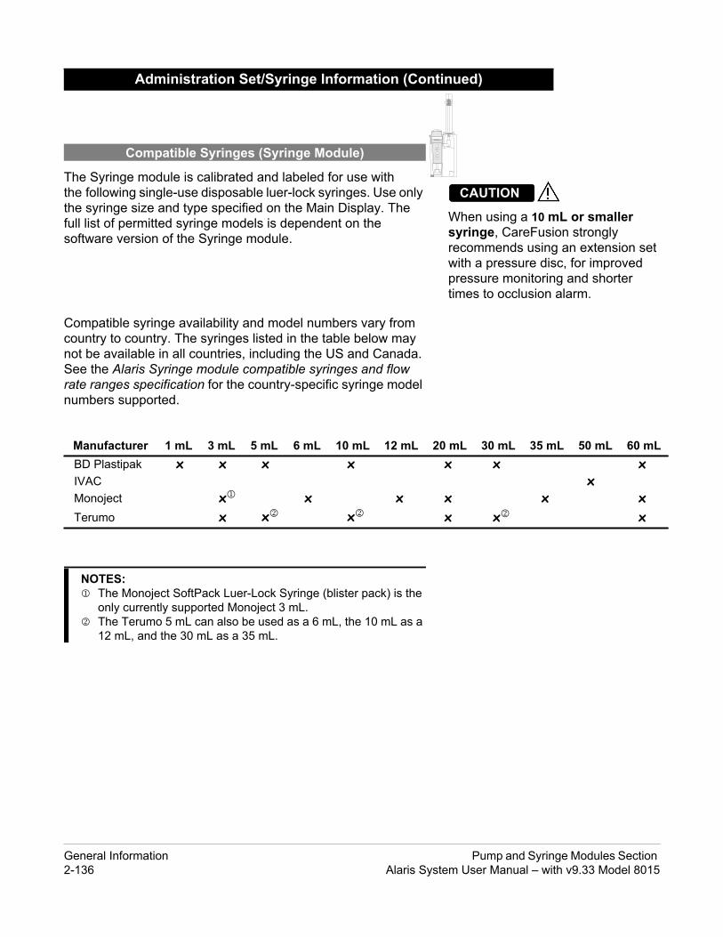
inued)
0 mL 30 mL 35 mL 50 mL 60 mLx x x
xx x xx x x
USE STANDBY
NNELLECT
NNELFF
USE
TART
(mL/h)
When using a 10 mL or smaller syringe, CareFusion strongly recommends using an extension set with a pressure disc, for improved pressure monitoring and shorter times to occlusion alarm.
CAUTION
The Syringe module is calibrated and labeled for use with the following single-use disposable luer-lock syringes. Use only the syringe size and type specified on the Main Display. The full list of permitted syringe models is dependent on the software version of the Syringe module.
Compatible syringe availability and model numbers vary from country to country. The syringes listed in the table below may not be available in all countries, including the US and Canada. See the Alaris Syringe module compatible syringes and flow rate ranges specification for the country-specific syringe model numbers supported.
Administration Set/Syringe Information (Cont
Compatible Syringes (Syringe Module)
Manufacturer 1 mL 3 mL 5 mL 6 mL 10 mL 12 mL 2BD Plastipak x x x xIVACMonoject x x xTerumo x x x
ALARM INF
CHASE
CHAO
PA
RES
RATE
NOTES: The Monoject SoftPack Luer-Lock Syringe (blister pack) is the
only currently supported Monoject 3 mL. The Terumo 5 mL can also be used as a 6 mL, the 10 mL as a
12 mL, and the 30 mL as a 35 mL.
General Information Pump and Syringe Modules Section 2-136 Alaris System User Manual – with v9.33 Model 8015

nd definitions.
Syringe Modules
odule can be paused indefinitely akes it possible to have additional
ssible when operating in that mode.
using either Drug Library or drug with or without a Continuous Infusion
Delay Options" definition) can be ion is to be initiated, After an infusion , or no alert (None).
. It provides a hospital-defined list of ssage Display, and identifies module rmation.
s allowed for a particular drug in a
start of an infusion a) for up to 23 hours 59 minutes.
lert to occur each time a dose limit is provides an indicator ("" or "LLL")
itial soft Alert to occur when a dose g beyond dose limit does not receive ovides an indicator ("" or "LLL")
usion (Alaris System calculates se),
sion (Alaris System calculates
ALARM INFUSE STANDBY
CHANNELSELECT
CHANNELOFF
PAUSE
RESTART
RATE (mL/h)
CHANNELSELECT
CHANNELOFF
RESTART
PAUSE
ALARM INFUSE STANDBY
RATE (mL/h)
Features and Displays
Features and Definitions
See the PC unit section of this User Manual for system features a
Feature Definition—Pump and
Anesthesia Mode When operating in Anesthesia Mode, a mwithout an alarm. Anesthesia Mode also mdrugs in each Profile, which are only acce
Bolus Dose Allows a bolus infusion to be programmedcalculation feature. It can be programmed following a bolus.
Callback A callback for a programmed delay (see "scheduled to give an alert Before an infusis completed, Before and After an infusion
Channel Labels Available when Profiles feature is enabledlabels, displayed in Channel (module) Mewith catheter location or other helpful info
Concentration Limits
Limits specified for range of concentrationProfile.
Delay Options Allows system to be programmed to delay120 minutes or b) for a specific time up to
Dose Checking Always Dose Checking option causes an Aexceeded. Drug label in Message Display that dose is beyond current Soft Limit.Smart Dose Checking option causes an inlimit is exceeded. Subsequent programminan Alert. Drug label in Message Display prthat dose is beyond current Soft Limit.
Drug Calculation Allows:• entry of drug dose for a Continuous Inf
correct flow rate to achieve desired doOR
• entry of flow rate for a Continuous Infucorresponding drug dose).
Pump and Syringe Modules Section General InformationAlaris System User Manual – with v9.33 Model 8015 2-137

Syringe Modules
es a hospital-defined list of drugs and any as 30 Profiles. Drug Library use
drug name, drug amount and diluent d best-practice limits. Drug Library econdary, or both, as determined by
n of an Intermittent Infusion.
phically displays current patient-side tient-side operating pressure for that
namic Pressure Display" information.)
ons.
Continuous Infusion dose, duration, r Bolus Dose duration.
for example, TPN) and limits around
eline determined by hospital/health t. Supports concentration Limits for
file-specific Limits can be defined area (BSA), maximum and minimum n for each drug in a Drug Library.
by hospital/health system as a Hard
t cannot be overridden, except in
t can be overridden.
equally spaced intervals on the mode is designed to allow delivery container at regularly scheduled
e delivered, as defined by facility’s
recall previous rate and volume ly available if patient is not new and
st usage.
ALARM INFUSE STANDBY
CHANNELSELECT
CHANNELOFF
PAUSE
RESTART
RATE (mL/h)
CHANNELSELECT
CHANNELOFF
RESTART
PAUSE
ALARM INFUSE STANDBY
RATE (mL/h)
Features and Displays (Continued)
Features and Definitions (Continued)
Feature Definition—Pump and
Drug Library When Profiles feature is enabled, it providconcentrations appropriate for use in as mautomates programming steps, including volume, and activates hospital-establisheentries can be delivered as a primary or shospital-health system.
Duration Limits Hospital-established limits around duratio
Dynamic Pressure Display
Appears on Main Display. If enabled, it graocclusion pressure set point and current pamodule. (See "Displays" for additional "Dy
Event Logging Event Logging records instrument operati
Initial Value An optional and editable starting value forBolus Dose, bolus rate of administration o
IV Fluid Library An optional library consisting of IV Fluids (rate of delivery.
Limit A programming Limit or best-practice guidsystem and entered into system’s Data Seall infusions that utilize concentration. Profor flow rate, patient weight, body surfacecontinuous dose, or total dose and duratioDose and duration Limits can be defined and/or Soft Limits.• A Hard Limit is a programmed Limit tha
anesthesia mode.• A Soft Limit is a programmed Limit tha
Multidose Mode Allows 2 - 24 doses to be programmed atsame module over a 24-hour period. Thisof multiple, equal doses from the same IVintervals.
Rapid Bolus Fastest rate at which Bolus Dose should bclinical best-practice guidelines.
Restore To simplify programming, can be used to settings for same patient. This option is onsystem is powered up within 8 hours of la
General Information Pump and Syringe Modules Section 2-138 Alaris System User Manual – with v9.33 Model 8015

Syringe Modules
nical indication for delivery of that r same medication with different
ose of infusion.
duration (infusion time) to be alculated.
ump Module
Occlusion Detection system nt-side occlusion alarms. Allows infusion following detection of a pressure falls to an acceptable level period. If this feature is enabled, n downstream pressure exceeds
ssure limit is either user-adjustable n.e limit is a function of flow rate and is e.
o a predetermined level, (below d "Checking Line" period, infusion is not cleared within 15 seconds, a rm occurs. can be configured to allow 0 (zero)
0-minute period. If allowable number s set to zero, an "Occluded - Patient ects downstream pressure that
e is set to 9 and is not configurable.
ch can be configured by Profile in
ALARM INFUSE STANDBY
CHANNELSELECT
CHANNELOFF
PAUSE
RESTART
RATE (mL/h)
CHANNELSELECT
CHANNELOFF
RESTART
PAUSE
ALARM INFUSE STANDBY
RATE (mL/h)
CHANNELSELECT
CHANNELOFF
RESTART
PAUSE
ALARM INFUSE STANDBY
RATE (mL/h)
Features and Displays (Continued)
Features and Definitions (Continued)
Feature Definition—Pump and
Therapies An optional hospital-defined therapy or cliinfusion. Different Limits can be defined fotherapeutic indications.
Total Dose Limits Hospital-established Limits around total d
Volume/Duration Allows a volume-to-be-infused (VTBI) andprogrammed. Flow rate is automatically c
Feature Definition—P
Auto-Restart Part of Alaris System’s Downstreamdesigned to minimize nuisance, patiesystem to automatically continue an patient-side occlusion if downstreamwithin a 15-second "Checking Line" "Checking Line" function occurs whepressure limit.• In Selectable Pressure Mode: Pre
or "locked" in system configuratio• In Pump Pressure Mode: Pressur
automatically determined by devicIf downstream pressure decreases t50% pressure limit) during 15-seconautomatically continues. If condition "Partial Occlusion - Patient Side" alaUsing the Editor software, the systemto 9 restart attempts within a rolling 1of restarts is exceeded or if feature iSide" alarm occurs when system detexceeds pressure limit.NOTE: Auto-Restart for Anesthesia Mod
Default Occlusion Pressure
Starting occlusion pressure limit whi25 mmHg increments.
Pump and Syringe Modules Section General InformationAlaris System User Manual – with v9.33 Model 8015 2-139

ump Module
sion System administration sets use mp on the lower fitment) to prevent ation set is removed from instrument.
n) rate (0.1 to 20 mL/h allowed), fusion Complete" occurs. KVO rate
clusion detection options is provided.ion alarm threshold is 525 mmHg at or rates less than 30 mL/h, occlusion ure rapid response to occlusions.nstream occlusion alarm threshold
ements, from 50 mmHg up to 25 mmHg.t" definition.)uid-side occlusion detection.
ndary) infusions can be infused, mes independent of primary infusion ccurs to primary infusion parameters if an Alaris Pump module/GEMINI tration set is used.
CHANNELSELECT
CHANNELOFF
RESTART
PAUSE
ALARM INFUSE STANDBY
RATE (mL/h)
Features and Displays (Continued)
Features and Definitions (Continued)
Feature Definition—P
Free Flow Protection All Alaris Pump module/GEMINI Infua unique clamping device (safety clainadvertent free-flow when administr
KVO Rate Adjust Used to select KVO (Keep Vein Opewhich is rate of fluid flow after an "Innever exceeds infusion rate.
Occlusion Pressure A complete range of downstream oc• Pump mode: Downstream occlus
flow rates of 30 mL/h or greater. Fpressure is rate-dependent to ens
• Selectable pressure mode: Dowcan be adjusted in 25 mmHg incrmaximum occlusion pressure of 5
• Auto-Restart: (See "Auto-RestarIn addition, Alaris System provides fl
Secondary Infusions Dual rate sequential piggyback (secowith limits, at delivery rates and voluparameters. Automatic changeover owhen secondary infusion is completeInfusion System check valve adminis
General Information Pump and Syringe Modules Section 2-140 Alaris System User Manual – with v9.33 Model 8015

yringe Module
to be infused (VTBI), the entire
g disc is in use, Auto Pressure option . Auto Pressure automatically sets , as follows:r less, system adds 30 mmHg to
alarm limit. 100 mmHg, system adds 30% to alarm limit.
alarm limits are temporarily raised to
e size and narrows down syringe
ministration set in use has a pressure reverses plunger movement during preocclusion levels, automatically
dministration set having a pressure s at an increased rate when an slack in drive mechanism.
n is complete and VTBI has reached
ns to automatically switch into KVO setting cannot be changed after ile selected.
ound anywhere from 1 to 60 minutes EOI alarm can be configured
infusions and intermittent infusions. ontinuous and intermittent infusions.
ALARM INFUSE STANDBY
CHANNELSELECT
CHANNELOFF
PAUSE
RESTART
RATE (mL/h)
Features and Displays (Continued)
Features and Definitions (Continued)
Feature Definition—S
All Mode When ALL is selected as the volumecontents of syringe is delivered.
Auto Pressure When enabled and a pressure sensinis displayed in Pressure Limit screenalarm limit for a shorter time to alarm• If current pressure is 100 mmHg o
current pressure to create a new • If current pressure is greater than
current pressure to create a new
Auto Pressure Limit Adjustment
When a bolus is delivered, pressure maximum limit.
Auto Syringe Size Identification
System automatically detects syringselection list.
Back Off This feature is only available when adsensing disc. When enabled, motor an occlusion until pressure returns toreducing bolus flow.
Fast Start When Fast Start is enabled and an asensing disc is used, instrument runinfusion is first started, taking up any
Infusion Complete An alert is given when current infusiozero.
KVO If enabled, allows continuous infusiomode upon completion. KVO option instrument is powered on and a Prof
Near End of Infusion (NEOI)
Allows an alarm to be configured to sprior to the end of the infusion. The Nseparately between continuous typeA separate alert time can be set for c
NOTE: If the duration of the programmed infusion is less than or equal
to the configured limit set in the Guardrail Editor, the NEOI alarm will occur at the start of the infusion.
Pump and Syringe Modules Section General InformationAlaris System User Manual – with v9.33 Model 8015 2-141

yringe Module
EOI alarm has been silenced. This is
al and only available when pressure
clusion detection options is provided.stream occlusion alarm threshold is
mmHg, in 1 mmHg increments.wnstream occlusion alarm threshold h.
c significantly improves instrument’s ster occlusion detection time, and
gs (see "Occlusion Pressure")
delivered in order to prime ected to a patient or after changing
ntinuous press of PRIME soft key
hen an empty syringe is detected.
lume in a syringe when it is inserted.
ALARM INFUSE STANDBY
CHANNELSELECT
CHANNELOFF
PAUSE
RESTART
RATE (mL/h)
Features and Displays (Continued)
Features and Definitions (Continued)
Feature Definition—S
NEOI Snooze Optional capability to remind users Nshared Syringe and PCA setting.
Numeric Pressure Display
Dynamic pressure display is numericsensing disc is inserted.
Occlusion Pressure A complete range of downstream oc• With pressure sensing disc: Down
selectable between 25 and 1000 • Without pressure sensing disc: Do
can be set to low, medium, or hig
Pressure Sensing Disc When installed, pressure sensing dispressure sensing capabilities for a famakes following features available:Auto PressureBack-OffCustomizable Pressure Alarm SettinFast StartPressure Tracking
Priming Allows a limited volume of fluid to beadministration set prior to being conna syringe. When priming, a single codelivers up to 2 mL of priming fluid.
Syringe Empty Instrument gives an alert and stops w
Syringe Volume Detection
System automatically detects fluid vo
General Information Pump and Syringe Modules Section 2-142 Alaris System User Manual – with v9.33 Model 8015

CHANNELSELECT
CHANNELOFF
RESTART
PAUSE
INFUSE STANDBY
TE (mL/h)
Rate Display
Channel (module) Message Display
Channel (module) Identification
Channel (module) Select Key: When pressed, selects corresponding module for infusion parameter entry and infusion setup.
Pause Key: When pressed during an infusion, temporarily stops infusion on that module. After approximately 2 minutes, a visual and audio prompt begins.
Channel (module) Off Key: When pressed and held until a beep is heard, stops infusion on that module, deselects that module, and if only that module had been operating, system powers down. Repeat for other operating modules to power off each module.
Restart Key: When pressed, resumes operation of a previously paused or alarmed infusion on that module.
IUI Connector, Right
Features and Displays (Continued)
Operating Features, Controls, IndicatorsALARM
RA
CHANNELSELECT
CHANNELOFF
RESTART
PAUSE
ALARM INFUSE STANDBY
RATE (mL/h)
Status Indicators
Module Release Latch: When pressed, allows module to be removed.
IUI Connector, Left
Door Handle
Alarm(red)
Infusing(green)
Standby(yellow)
Pump and Syringe Modules Section General InformationAlaris System User Manual – with v9.33 Model 8015 2-143

CHANNELSELECT
CHANNELOFF
RESTART
PAUSE
INFUSE STANDBY
TE (mL/h)
Upper Tubing Fitment Retainer
IUI Connector, Right
Upper Pressure Sensor
Upper Occluder
Upper Pumping Finger
Lower Occluder
Lower Pumping Finger
Lower Pressure Sensor
Safety Clamp Sensor and Door SensorAir-in-Line Sensor
Features and Displays (Continued)
Operating Features, Controls, Indicators (Continued)ALARM
RA
IUI Connector, Left(not visible)
Door Latch Cam/Slide
Tubing Keeper
Platen
General Information Pump and Syringe Modules Section 2-144 Alaris System User Manual – with v9.33 Model 8015

USE STANDBY
NNELLECT
NNELFF
USE
TART
(mL/h)
IUI Connector, Right
ducer/Pressure Sensing Disc Housing
Syringe Barrel Clamp/ Sizer
Gripper Control/Drive Head Release (shown in closed position)
Plunger Grippers (shown in closed position)
Barrel Flange Grippers
Syringe Barrel Sensor
en pressed,
Features and Displays (Continued)
Operating Features, Controls, Indicators (Continued)
ALARM INF
CHASE
CHAO
PA
RES
RATE
ALARM INFUSE STANDBY
CHANNELSELECT
CHANNELOFF
PAUSE
RESTART
RATE (mL/h)
IUI Connector, Left
Rate Display
Message Display
Channel (module) Identification
Channel (module) Select Key: When pressed, selects corresponding module for infusion parameter entry and infusion setup.
Pause Key: When pressed during an infusion, temporarily stops infusion on that module. After approximately 2 minutes, a visual and audio prompt begins.
Channel (module) Off Key: When pressed and held until a beep is heard, stops infusion on that module, deselects that module, and if only that module had been operating, system powers down. Repeat for other operating modules to power off each module.
Restart Key: When pressed, resumes operation of a previously paused or alarmed infusion on that module.
Pressure Trans
Status Indicators
Alarm(red)
Infusing(green)
Standby(yellow)
Module Release Latch: Whallows module to be removed.
Pump and Syringe Modules Section General InformationAlaris System User Manual – with v9.33 Model 8015 2-145

ALARM INFUSE STANDBY
CHANNELSELECT
CHANNELOFF
PAUSE
RESTART
RATE (mL/h)
CHANNELSELECT
CHANNELOFF
RESTART
PAUSE
INFUSE STANDBY
TE (mL/h)
Although the dynamic pressure display bars for the Syringe module and Pump module both use the full width of the screen for display, they each represent different ranges. The Pump module’s range is 50 to 525 mmHg and the Syringe module’s range is 25 to 1000 mmHg.
CAUTION
The displays illustrated throughout this document are for illustration purposes only. The display content varies, depending on configuration settings, type of administration set in use, hospital-defined Data Set uploaded using the Guardrails Suite MX, programmed drug calculation parameters, and many other variables. Refer to specific drug product labeling for information concerning appropriate administration techniques and dosages.
See the PC unit section of this User Manual.
Features and Displays (Continued)
Displays
Main Display
Dynamic Pressure Display
ALARM
RA
VTBI = 250.0 mL
VOLUMEINFUSED
Midtown HospitalAdult ICU
AUDIOADJUST
Patient-side occlusion pressure set point is indicated by tick mark.
The tick mark moves when the Pressure Limit changes.
Current operating pressure is indicated by solid bar.
Dynamic Pressure Display
General Information Pump and Syringe Modules Section 2-146 Alaris System User Manual – with v9.33 Model 8015

as
ALARM INFUSE STANDBY
CHANNELSELECT
CHANNELOFF
PAUSE
RESTART
RATE (mL/h)
CHANNELSELECT
CHANNELOFF
RESTART
PAUSE
ALARM INFUSE STANDBY
RATE (mL/h)
v
The Drug Calculation feature is to be used only by personnel properly trained in the administration of continuously infused medications. Extreme caution should be exercised to ensure the correct entry of the drug calculation infusion parameters.
WARNING
The Pump Module and Syringe module use the following parameters, entered during the drug calculation setup procedure:
• Bolus Dose duration: Time period over which Bolus Dose is to be administered.
• Bolus Dose units: Units used in calculating Bolus Dose. Bolus Dose units are selected from alternatives provided.
• Diluent volume: Volume of fluid used as diluent for drug (mL).
• Dosing units: Units used to calculate Continuous Infusion drug dose. Dosing Units are selected from alternatives provided.
• Drug amount: Amount of drug in IV container (gram, mg, mcg, mEq, or units).
• Patient weight: Weight of patient (kg); this is an optional parameter that is not needed unless drug dose is normalized for patient weight.
• Time units: Time base for all calculations (minute, hour, or day).
The Bolus Dose, drug dose, and flow rate parameters are calculated using the above parameters, as follows:
• Bolus Dose = Bolus Dose x patient weight (if used).
• Bolus Dose administration rate (INFUSE AT:):
When duration is entered = total dose / duration in minutes.When Max Rate is used = Max Rate / 60 x concentration.
• Bolus Dose duration = bolus VTBI / bolus rate.
• Bolus Dose VTBI = bolus dose / drug concentration.
• Bolus rate = bolus VTBI / duration.
• Continuous drug dose = flow rate x drug concentration (normalized for patient weight if specified by entering a patient weight).
• Continuous flow rate = drug dose / drug concentration (normalized for patient weight if specified by entering a patient weight).
• Duration = VTBI / rate.
• Drug concentration = drug amount / diluent volume.
• Rate = VTBI / duration.
Drug Calculation Definitions and Formul
Pump and Syringe Modules Section General InformationAlaris System User Manual – with v9.33 Model 8015 2-147

ntinued)
ALARM INFUSE STANDBY
CHANNELSELECT
CHANNELOFF
PAUSE
RESTART
RATE (mL/h)
CHANNELSELECT
CHANNELOFF
RESTART
PAUSE
ALARM INFUSE STANDBY
RATE (mL/h)
• Total Bolus Dose:
Bolus Dose not weight-based = Bolus Dose entered.Bolus Dose weight-based = Bolus Dose x patient weight.
• Total dose:
Drug amount.Drug amount / patient body surface area (BSA).Drug amount / patient weight.
See the PC unit section of this User Manual for system configurable settings.
If the configuration settings need to be changed from the Factory default settings, refer to the applicable Technical Service Manual or contact CareFusion Technical Support, for technical, troubleshooting, and preventive maintenance information.
With the Profiles feature enabled, the settings are configured independently for each Profile. A hospital-defined, best- practice Data Set must be uploaded to enable the Profiles feature. Date and Time is a system setting and is the same in all Profiles.
Drug Calculation Definitions and Formulas (Co
Configurable Settings
General Information Pump and Syringe Modules Section 2-148 Alaris System User Manual – with v9.33 Model 8015

Options
bledAfter, Before and After
bledbled
bledAfter, Before and After
bled
bled
ALARM INFUSE STANDBY
CHANNELSELECT
CHANNELOFF
PAUSE
RESTART
RATE (mL/h)
CHANNELSELECT
CHANNELOFF
RESTART
PAUSE
INFUSE STANDBY
ATE (mL/h)
x
xx
Configurable Settings (Continued)
Shared Infusion
Feature Default Setting
Delay Options• Callback
DisabledAfter
Enabled - DisaNone, Before,
Drug Calculation• Bolus Dose
DisabledDisabled
Enabled - DisaEnabled - Disa
Multidose• Callback
DisabledNone
Enabled - DisaNone, Before,
Pressure Dynamic(Dynamic Pressure Display)
Disabled Enabled - Disa
Volume/Duration Disabled Enabled - Disa
ALARM
R
Pump and Syringe Modules Section General InformationAlaris System User Manual – with v9.33 Model 8015 2-149

Options
bled
mcLde only: 500 mcL
de only: 9 attempts
in 0.1 mL/h increments; in 1 mL/h increments
blekedg in 25 mmHg increments (adjustable ble Pressure Mode)g in 25 mmHg increments (configured adjustable only in Selectable Pressure
bled
bled
ALARM INFUSE STANDBY
CHANNELSELECT
CHANNELOFF
PAUSE
RESTART
RATE (mL/h)
CHANNELSELECT
CHANNELOFF
RESTART
PAUSE
ALARM INFUSE STANDBY
RATE (mL/h)
CHANNELSELECT
CHANNELOFF
RESTART
PAUSE
INFUSE STANDBY
TE (mL/h)
Configurable Settings (Continued)
Pump Module
Feature Default Setting
Accumulated Air Enabled Enabled - Disa
Air-in-Line Settings(single bolus)
75 mcL 50, 75, or 250 Anesthesia Mo
Auto-Restart Attempts 0 0 - 9 attemptsAnesthesia Mo
KVO (Keep Vein Open) 1 mL/h 0.1 - 20 mL/h
Max Rate 999 mL/h 0.1 - 99.9 mL/h100 - 999 mL/h
Max VTBI 9999 mL 0.1 - 9999 mL
Pressure Mode• Mode Selection• Lock Status• Max Occlusion Pressure
• Default Starting Occlusion Pressure
PumpUnlocked
525 mmHg
525 mmHg
Pump, SelectaLocked, Unloc50 - 525 mmHonly in Selecta50 - 525 mmHby Profile and Mode)
SEC to PRI Alert Enabled Enabled - Disa
Secondary (Dual Rate Sequential Piggybacking)
Disabled Enabled - Disa
ALARM
RA
General Information Pump and Syringe Modules Section 2-150 Alaris System User Manual – with v9.33 Model 8015

Options
bled
bled
bled
bled
bled (0.01 - 0.09 mL/h available for 1 mL ges)d on the total syringe size, not the in the syringe)
in 0.1 mL/h increments; in 1 mL/h increments
bled bled
blednutes
g in 1 mmHg incrementsg)mHg)g)
bled
USE STANDBY
NNELLECT
NNELFF
USE
TART
(mL/h)
Configurable Settings (Continued)
Syringe Module
Feature Default Setting
ALL Mode Disabled Enabled - Disa
Auto Pressure Disabled Enabled - Disa
Back Off (after occlusion) Enabled Enabled - Disa
Fast Start Enabled Enabled - Disa
KVO (Keep Vein Open)• Rate Adjust
• Volume Adjust
Disabled1 mL/h
5%
Enabled - Disa0.01 - 2.5 mL/hand 3 mL syrin0.5 - 5% (Basevolume of fluid
Max Rate 999 mL/h 0.1 - 99.9 mL/h100 - 999 mL/h
Near End (NEOI)• Continuous Alert Time• Intermittent NEOI• Intermittent Alert Time
Disabled60
Disabled15
Enabled - Disa1 - 60 minutesEnabled - Disa1 - 60 minutes
NEOI Snooze (Shared Syringe and PCA setting)
Disabled Enabled - Disa5, 10, or 15 mi
Occlusion Pressure Set Point• With Disc• No Disc
1000 mmHgHigh*
25 - 1000 mmHLow (200 mmHMedium (500 mHigh (800 mmH
Priming Disabled Enabled - Disa
ALARM INF
CHASE
CHAO
PA
RES
RATE
NOTE:*Occlusion Pressure Point cannot be set higher than the default setting.
Pump and Syringe Modules Section General InformationAlaris System User Manual – with v9.33 Model 8015 2-151

in the event of a single fault condition is
tem must remain in an upright position.
CHANNELSELECT
CHANNELOFF
RESTART
PAUSE
INFUSE STANDBY
TE (mL/h)
Air that Causes Alarm
Volume (mL) that Causes Alarm
10% 0.2820% 1.630% 2.430% 2.4
hes of airhes of airhes of air
/h) Bolus Volume (mL)0.30.6
g Storage/Transport
mHg hPa)
375 - 760 mmHg(500 - 1013 hPa)
sing5 - 85%
Noncondensing
°F)
-4 - 140°F(-20 - 60°C)
Specifications
Pump Module
Accumulated Air Window:
Bolus Volume, Maximum after Occlusion:
Critical Volume: Maximum over-infusion that can occur 0.6 mL.
Dimensions: 3.3" W x 8.9" H x 5.5" D
Environmental Conditions:
Equipment Orientation: To ensure proper operation, Alaris Sys
ALARM
RA
Single Bolus Setting (mcL)
Volume Window (mL)
%
50 2.875 8.0250 8.0
500 12.0
NOTE: In a standard bore tubing set:
50 mcL is approximately 0.34 inc75 mcL is approximately 0.51 inc250 mcL is approximately 1.7 inc
In Anesthesia Mode only.
Pressure Limit (mmHg Rate (mL50 25525 25
Operatin
Atmospheric Pressure 525 - 4560 m(700 - 6080
Relative Humidity(Avoid prolonged exposure to relative humidity >85%)
20 - 90%Nonconden
Temperature Range 41 - 104(5 - 40°C
General Information Pump and Syringe Modules Section 2-152 Alaris System User Manual – with v9.33 Model 8015

50, 75, or 250 microliters nominal
Threshold plus tolerance)
ate is 1 mL/h or above; or set rate, if rate
ration from 0.1 - 20 mL/h in 0.1 mL/h
L/hte and patient back–pressure at rates
25 mmHg in 25 mmHg increments.
CHANNELSELECT
CHANNELOFF
RESTART
PAUSE
INFUSE STANDBY
TE (mL/h)
ments (mL/h)Device Calculated Rates
0.010.11
Specifications (Continued)
Pump Module (Continued)
Flow Rate Programming Increments:
Fluid Ingress Protection: IPX1, Drip Proof
Infusion of Air, Means to Protect Patient from:
Ultrasonic Air-in-Line DetectionMaximum single bolus size = selectable(500 microliters in Anesthesia Mode)
Infusion Pressure, Maximum:
654 mmHg (Maximum Occlusion Alarm
KVO (Keep Vein Open) Rate:
Factory default setting is 1 mL/h if set ris 0.9 mL/h or below.
KVO Selection Range: KVO rate can be set in System Configuincrements.
Occlusion Alarm Thresholds:
Pump Mode: 525 mmHg at rates ≥30 mVarying level based on ra<30 mL/h.
Selectable Mode: User selected, 50 - 5
Operating Principle: Positive displacement
ALARM
RA
Rate Range(mL/h)
IncreUser Input Rates
0.1 - 9.99 0.110 - 99.9100 - 999 1
Pump and Syringe Modules Section General InformationAlaris System User Manual – with v9.33 Model 8015 2-153

at rates between 1 and 999 mL/h and e with 95% confidence, under conditions
L/h ±2°C)bove top of Pump moduleter
kPa)
lied part.
CHANNELSELECT
CHANNELOFF
RESTART
PAUSE
INFUSE STANDBY
TE (mL/h)
sure, or any combination of these that can influence head height and et configuration, IV solution viscosity, ressure can also be affected by type -Up Curves” for data on how these
mL/h) Time to Alarm1 5 minutes5 5 seconds
1 5 minutes5 2 minutes
Specifications (Continued)
Pump Module (Continued)
Rate Accuracy: Rate accuracy of Alaris System is ±5%±5.5% at rates <1 mL/h, 95% of the timlisted below.Infusion Rate Range: 0.1 - 999 mAmbient Temperature: 68 ±4°F (20Source Container Height: 20 inches aTest Solution: Distilled WaDistal Back pressure: 0 mmHg (0Needle: 18 gaugeAdministration Set Model: 2210
Shock Protection: Type CF, Defibrillator Proof patient app
Time to Alarm, Maximum:
Volume to be Infused Programming Increments:
Weight: 2.6 lbs
ALARM
RA
Variations of head height, back prescan affect rate accuracy. Factors back pressure are: Administration sand IV solution temperature. Back pof catheter. See “Trumpet and Startfactors influence rate accuracy.
WARNING
Pressure Limit (mmHg) Rate (5050 2525525 2
Range (mL) Increments (mL)0.1 - 9.99 0.0110 - 999.9 0.1
1000 - 9999
NOTE:The minimum Volume To Be Infused (VTBI) for both LVP and Syringe module (applicable to all syringe sizes) is 0.1mLs. This applies to Continuous Infusions, Bolus Dose, Intermittent Infusions, and IV Fluids.
General Information Pump and Syringe Modules Section 2-154 Alaris System User Manual – with v9.33 Model 8015

c after an infusion has started can
feature that, when enabled and a esigned to reduce bolus volume on
INFUSE STANDBY
CHANNELSELECT
CHANNELOFF
PAUSE
RESTART
RATE (mL/h)
me (mL)263
Bolus Volume (mL)Disabled Back Off Enabled62 0.12675 0.33139 0.323
Specifications (Continued)
Syringe Module
Bolus Volume, Maximum after Occlusion:
Installing a pressure sensing disresult in a bolus to the patient.
Without Pressure Sensing Disc:
With Pressure Sensing Disc:
Alaris System has a back-off safetypressure sensing disc is in use, is docclusion release.
ALARM
WARNING
Pressure Setting Bolus VoluLow 0.51
Medium 0.77High 1.10
Pressure Setting Back Off 300 mmHg 0.4500 mmHg 0.51000 mmHg 0.8
Pump and Syringe Modules Section General InformationAlaris System User Manual – with v9.33 Model 8015 2-155

ons are based on following standard
95 mmHg
%
0 mL
mately 2 minutes
occur in the event of a single-fault inal syringe fill volume during loading
after syringe loading.
System must remain in an upright position.
USE STANDBY
NNELLECT
NNELFF
USE
TART
(mL/h)
Operating Storage/Transport
525 - 4560 mmHg(700 - 6080 hPa)
375 - 760 mmHg(500 - 1013 hPa)
20 - 90%Noncondensing
5 - 85%Noncondensing
41 - 104°F(5 - 40°C)
-4 - 140°F(-20 - 60°C)
Specifications (Continued)
Syringe Module (Continued)
Bolus Volume, Maximum after Occlusion: (Continued)
Maximum Bolus Volume specificatioperating conditions:Atmospheric Pressure: 645 - 7Disposable Type: No Pressure Disc: #30914 With Pressure Disc: #30920Humidity: 20 - 90Rate: 5 mL/hSyringe Type: BD 50/6Temperature: 68 ±4°FVolume Collection Time: approxi
Critical Volume: Maximum over-infusion which can condition will not exceed 2% of nomand 1% of maximum syringe travel
Dimensions: 4.5" W x 15.0" H x 7.5" D
Environmental Conditions:
Equipment Orientation: To ensure proper operation, Alaris
ALARM INF
CHASE
CHAO
PA
RES
RATE
Symbol Meaning
Atmospheric Pressure
Relative Humidity(Avoid prolonged exposure to relative humidity >85%)
Temperature Range
General Information Pump and Syringe Modules Section 2-156 Alaris System User Manual – with v9.33 Model 8015

mL/h and can be selected as follows:
proximately 800 mmHg (actual syringe size and manufacturer)mmHg
et rate is 1 mL/h or above; or set rate, if
figuration, in 0.01 mL/h increments, as
vailable for 1 mL and 3 mL syringes)
ree settings—Low, Medium, Highselected, 25 - 1000 mmHg in 1 mmHg
USE STANDBY
NNELLECT
NNELFF
USE
TART
(mL/h)
e Increments (mL/h)0.010.11
te Range (mL/h).1 - 999.1 - 650.1 - 500.1 - 250.1 - 150.01 - 100.01 - 30
Specifications (Continued)
Syringe Module (Continued)
Flow Rate Programming: Flow rate range is from 0.01 to 999
Rate Restriction by Syringe Size:
Fluid Ingress Protection: IPX1, Drip Proof
Infusion Pressure, Maximum: Without Pressure Sensing Disc: apocclusion pressure varies based onWith Pressure Sensing Disc: 1060
KVO (Keep Vein Open) Rate: Factory default setting is 1 mL/h if srate is 0.9 mL/h or below.
KVO Rate Range: KVO rate can be set in System Confollows:0.01 - 2.5 mL/h (0.01 - 0.09 mL/h a
Occlusion Alarm Thresholds: Without Pressure Sensing Disc: ThWith Pressure Sensing Disc: User increments.
Operating Principle: Positive displacement
ALARM INF
CHASE
CHAO
PA
RES
RATE
Flow Rates (mL) Selectabl0.01 - 9.9910 - 99.9100 - 999
Syringe Size (mL) Flow Ra50/60 0
30 020 010 05 03 01 0
Pump and Syringe Modules Section General InformationAlaris System User Manual – with v9.33 Model 8015 2-157

t including syringe variation)
ons are based on following standard
95 mmHgg before producing occlusion
%0 mL
USE STANDBY
NNELLECT
NNELFF
USE
TART
(mL/h)
variations of back pressure, or any t rate accuracy. Factors that can ministration set configuration, IV n temperature. Back pressure can eter. See “Trumpet and Start-Up actors influence rate accuracy.
essure LimitWith Disc Highest
(1000 mmHg) Setting105 minutes30 minutes
)
Specifications (Continued)
Syringe Module (Continued)
Rate Accuracy: ±2% of full scale plunger travel (no
Shock Protection: Type CF, Defibrillator Proof
Time to Alarm, Maximum:
Maximum Time to Alarm specificatioperating conditions:Atmospheric Pressure: 645 - 7Back Pressure: 0 mmHDisposable Type: No Pressure Disc: #30914 With Pressure Disc: #30920Humidity: 20 - 90Syringe Type: BD 50/6Temperature: 68 ±4°F
Volume to be Infused Programming Increments:
Weight: 4.5 lbs
ALARM INF
CHASE
CHAO
PA
RES
RATE
Syringe size and running force, combination of these can affecinfluence back pressure are: Adsolution viscosity, and IV solutioalso be affected by type of cathCurves” for data on how these f
WARNING
Pr
Rate (mL/h) No DiscHigh Setting
1 120 minutes5 30 minutes
NOTE:The minimum Volume To Be Infused (VTBI) for both LVP and Syringe module (applicable to all syringe sizes) is 0.1mLs. This applies to Continuous Infusions, Bolus Dose, Intermittent Infusions, and IV Fluids.
Range (mL) Increments (mL0.01 - 9.99 0.01
10 - 60 0.1
General Information Pump and Syringe Modules Section 2-158 Alaris System User Manual – with v9.33 Model 8015

inge Modules
ion alarms have been acknowledged reactivate a previously silenced alarm
e alarm audio will resume.
nts filter size.
d should not be accessed by a
glass symbol.
odule
ified on drop symbol.
ALARM INFUSE STANDBY
CHANNELSELECT
CHANNELOFF
PAUSE
RESTART
RATE (mL/h)
CHANNELSELECT
CHANNELOFF
RESTART
PAUSE
ALARM INFUSE STANDBY
RATE (mL/h)
Symbols
See the PC unit section of this User Manual for system symbols.
Symbol Meaning—Pump and Syr
The Infusion Alarm Silence symbol indicates that infusand silenced. Press the CANCEL SILENCE soft key toaudio. If the alarm condition has not been resolved, th
Type CF defibrillation-proof patient applied part.
Single-Use. Do not reuse.
Product contains micron filter, where XX represe
DEHP in fluid pathway.
Non-DEHP plasticizer in fluid pathway.
No DEHP in fluid pathway.
Product is latex-free.
Product incorporates Needle-Free Valve ports anneedle.
Approximate administration set priming volume.
Expiration date for product is identified near hour
Do not use if package is damaged.
Manufacturer
Symbol Meaning—Pump M
Drops per milliliter specification for product is ident
2Single-Use
XXµm
DEHP
NONDEHP
DEHP
LATEX
� XX ml
XX
Pump and Syringe Modules Section General InformationAlaris System User Manual – with v9.33 Model 8015 2-159

CHANNELSELECT
CHANNELOFF
RESTART
PAUSE
INFUSE STANDBY
TE (mL/h)
In this instrument, as with all infusion systems, the action of the pumping mechanism and variations in individual administration sets cause short-term fluctuations in rate accuracy. The following graphs show typical performance of the system, as follows:
• Accuracy during various time periods over which fluid delivery is measured (trumpet curves).
• Delay in onset of fluid flow when infusion commences (start-up curves).
Trumpet curves are named for their characteristic shape. They display discrete accuracy data averaged over particular time periods or "observation windows," not continuous data versus operating time.
Over long observation windows, short-term fluctuations have little effect on accuracy, as represented by the flat part of the curve. As the observation window is reduced, short-term fluctuations have greater effect, as represented by the "mouth" of the trumpet. Knowledge of system accuracy over various observation windows might be of interest when certain drugs are being administered.
Because the clinical impact of short-term fluctuations on rate accuracy depends on the half-life of the drug being infused and on the degree of intravascular integration, the clinical effect cannot be determined from the trumpet curves alone. Knowledge of the start-up characteristics should also be considered.
The start-up curves represent continuous flow rate versus operating time for 2 hours from the start of the infusion. They exhibit the delay in onset of delivery due to mechanical compliance and provide a visual representation of uniformity. Trumpet curves are derived from the second hour of this data.
Effects of Pressure Variations
Under conditions of +100 mmHg pressure, the Pump module typically exhibits a long-term accuracy offset of approximately -3.5% from mean values.
Trumpet and Start-Up Curves
Pump Module
ALARM
RA
General Information Pump and Syringe Modules Section 2-160 Alaris System User Manual – with v9.33 Model 8015

)
CHANNELSELECT
CHANNELOFF
RESTART
PAUSE
INFUSE STANDBY
TE (mL/h)
USE STANDBY
NNELECT
NNELFF
USE
TART
(mL/h)
Under conditions of +300 mmHg pressure, the Pump module typically exhibits a long-term accuracy offset of approximately -6.2% from mean values.
Under conditions of -100 mmHg pressure, the Pump module typically exhibits a long-term accuracy offset of approximately +0.5% from mean values.
Resulting trumpet observation points typically track those of accuracy; therefore, no significant change in short-term variations result under these pressure conditions.
Effects of Negative Solution Container Heights
With a negative head height of -0.5 meters, the Pump module typically exhibits a long-term accuracy offset of approximately -2.8% from mean values.
Resulting trumpet observation points typically track those of accuracy; therefore, no significant change in short-term variations result under negative head height conditions.
Trumpet and start-up curves have been provided for 1.0 mL/h and 5.0 mL/h. Measurements for trumpet curve rates below 1.0 mL/h are not provided because of the difficulty in measuring extremely small volumes over a large duration of time. In this case, the linear relationship of the plunger position and velocity to syringe volume and rate is verified, and is a function of the accuracy of the design.
Measurements for trumpet curve rates above 5.0 mL/h are also not provided, as the syringe volume is displaced in a very short time with a rate up to 999 mL/h. Accuracy, however, is assured with the design implementation.
Under conditions of -100 mmHg, +100 mmHg, and +300 mmHg pressures, the Syringe module typically exhibits a long-term accuracy offset of approximately 0.2% or less from the mean value.
Trumpet and Start-Up Curves (Continued
Pump Module (Continued)
Syringe Module
ALARM
RA
ALARM INF
CHASEL
CHAO
PA
RES
RATE
Pump and Syringe Modules Section General InformationAlaris System User Manual – with v9.33 Model 8015 2-161

)
Legend:Maximum rate errorOverall rate errorMinimum rate error
Trumpet and Start-Up Curves (Continued
Graphs
Pump Module CHANNELSELECT
CHANNELOFF
RESTART
PAUSE
ALARM INFUSE STANDBY
RATE (mL/h)
NOTE: The plot range has been increased to ±100% to allow visualization of the graph.
General Information Pump and Syringe Modules Section 2-162 Alaris System User Manual – with v9.33 Model 8015

)
Legend:Maximum rate errorOverall rate errorMinimum rate error
Trumpet and Start-Up Curves (Continued
Graphs—Pump Module (Continued)
Pump Module CHANNELSELECT
CHANNELOFF
RESTART
PAUSE
ALARM INFUSE STANDBY
RATE (mL/h)
Pump and Syringe Modules Section General InformationAlaris System User Manual – with v9.33 Model 8015 2-163

)
Start-Up Curve at 5 mL/h (initial) 1 g/mL
Time (min)
.3
.8
-0.9
-2.2
-1.1
-1.9
-1.3
-1.8
Trumpet Curve at 5 mL/h (initial)
Observation Interval (min)
Legend:Maximum rate errorOverall rate errorMinimum rate error
Trumpet and Start-Up Curves (Continued
Graphs (Continued)
Syringe ModuleALARM INFUSE STANDBY
CHANNELSELECT
CHANNELOFF
PAUSE
RESTART
RATE (mL/h)
Start-Up Curve at 1 mL/h (initial) 1 g/mL
Time (min)
(mL
/h)
(mL
/h)
0.3
-2.6
-5.3
-0.7
-4.1
-1.4
-3.6
-1.8
-3.2
-2.1
-3.1
Trumpet Curve at 1 mL/h (initial)
Observation Interval (min)
Flo
wR
ate
Err
or
(%)
1.1
-1.6
-4.2
-0
-2
Flo
wR
ate
Err
or
(%)
General Information Pump and Syringe Modules Section 2-164 Alaris System User Manual – with v9.33 Model 8015

Alaris System User Manual – with v9.33 Model 8015 Section 3
Alaris PCA ModuleModel 8120
ALARM INFUSE STANDBY
CHANNELSELECT
CHANNELOFF
PAUSE
RESTART
RATE (mL/h)

T H I S P A G EI N T E N T I O N A L L Y
L E F T B L A N K

Getting StartedIntroduction............................................................................................................................................. 3-1Attach and Detach Dose Request Cord ................................................................................................. 3-2Prepare and Load Syringe and Administration Set ................................................................................ 3-3
Prepare Syringe and Administration Set ........................................................................................ 3-3Load Syringe and Administration Set ............................................................................................. 3-4Security Lock Key Positions ........................................................................................................... 3-6
ProgrammingPrepare Infusion..................................................................................................................................... 3-7
Select Syringe Type and Size ........................................................................................................ 3-7Prime .............................................................................................................................................. 3-8Program an Infusion ....................................................................................................................... 3-10
Infusion Modes....................................................................................................................................... 3-12Programming Parameters .............................................................................................................. 3-12Set Up PCA Dose Only .................................................................................................................. 3-13Set Up Continuous Infusion Only ................................................................................................... 3-15Set Up PCA Dose and Continuous Infusion ................................................................................... 3-17Set Loading Dose Only................................................................................................................... 3-20Set Bolus Dose............................................................................................................................... 3-22Stop a Loading, PCA, or Bolus Dose ............................................................................................. 3-25Change Programming Parameters During an Infusion................................................................... 3-26View Patient History ....................................................................................................................... 3-27Clear Patient History....................................................................................................................... 3-28View Drug Event History................................................................................................................. 3-30Configure Dose Request Cord ....................................................................................................... 3-30Security Access Levels................................................................................................................... 3-32Disable Security Access Code ....................................................................................................... 3-32Pause Infusion................................................................................................................................ 3-33Change Syringe and Restore Infusion............................................................................................ 3-34Stop Infusion................................................................................................................................... 3-35Select Pressure Limit...................................................................................................................... 3-36View and Clear Volume Infused ..................................................................................................... 3-36
PCA Pause Protocol Feature ................................................................................................................. 3-37Program an Infusion ....................................................................................................................... 3-37Review or Change PCA Pause Alarm Limits.................................................................................. 3-39Disable PCA Pause Alarm.............................................................................................................. 3-40
General Setup and OperationSystem Start-Up/Setup........................................................................................................................... 3-43
General InformationWarnings and Cautions.......................................................................................................................... 3-45
General........................................................................................................................................... 3-45Administration Sets......................................................................................................................... 3-45Epidural Administration................................................................................................................... 3-47Dose Request Cord ........................................................................................................................ 3-47Guardrails Software........................................................................................................................ 3-48
Table of Contents
PCA Module Section Table of ContentsAlaris System User Manual – with v9.33 Model 8015 3-iii

Administration Set/Syringe Information .................................................................................................. 3-48Compatible Syringes .............................................................................................................................. 3-49Features and Displays............................................................................................................................ 3-49
Features and Definitions................................................................................................................. 3-49Operating Features, Controls, Indicators........................................................................................ 3-55Displays .......................................................................................................................................... 3-56
Configurable Settings............................................................................................................................. 3-56Specifications and Symbols ................................................................................................................... 3-58
Specifications ................................................................................................................................. 3-58Symbols.......................................................................................................................................... 3-61
Trumpet and Start-Up Curves ................................................................................................................ 3-62
Table of Contents PCA Module Section3-iv Alaris System User Manual – with v9.33 Model 8015

Getting Started
Read all instructions, for both the PCA module and PC unit, before using the Alaris System.
WARNING
This section of the User Manual provides PCA module (Model 8120) instructions and information. It is used in conjunction with:
• Alaris product administration set instructions• Drug product labeling• PCA Module Technical Service Manual• PC unit chapter of this User Manual• System Maintenance software (and its instructions) for
Alaris System check-in, maintenance, and wireless configuration
The PCA module (Patient Controlled Analgesia) is intended for facilities that use syringe pumps for the delivery of medications or fluids. The PCA module is indicated for use on adults, pediatrics and neonates for continuous or intermittent delivery through clinically acceptable routes of administration; such as, intravenous (IV), subcutaneous or epidural. Only one PCA module can be connected to the Alaris System.
Administration Sets/Syringes: See "General Information" for specific administration set and syringe instructions.
• Administration Set Information• Compatible Syringes
Alarms, Errors, Messages: See "Troubleshooting and Maintenance" for module-specific alarms, errors, and messages.
Contraindications: None known.
Electromagnetic Environment: See "Appendix" section of this User Manual ("Regulations and Standards," "Compliance").
Introduction
PCA Module Section Getting StartedAlaris System User Manual – with v9.33 Model 8015 3-1

Carefully locate the Dose Request Cord to reduce the possibility of patient entanglement or strangulation.
WARNING
Red alignment marks
Latching Connector
Dose Request Cord receptacle
The Dose Request Cord must be attached to the PCA module when delivering a PCA dose or PCA + continuous dose infusion.
To attach Dose Request Cord:
Insert latching connector into Dose Request Cord attachment. Red marking on latching connector should be aligned with red marking on Dose Request Cord receptacle.
To detach Dose Request Cord:
Hold body of latching connector and pull straight out, without twisting or turning, from Dose Request Cord receptacle.
Attach and Detach Dose Request Cord
Getting Started PCA Module Section3-2 Alaris System User Manual – with v9.33 Model 8015

n Set
Use only standard or pre-filled, single-use, disposable syringes (with luer-lock connectors) and nondedicated administration sets with integrated anti-siphon valves, designed for use on syringe-type PCA pumps. The use of any other syringe or administration set can cause improper instrument operation, resulting in inaccurate fluid delivery, pressure sensing, or other potential hazards. For a list of compatible syringes, refer to Compatible Syringes on page 3-49.
WARNING
Before loading or unloading the syringe, always turn off fluid flow to the patient, using the tubing clamp or stopcock. Uncontrolled fluid flow can occur when the administration set is not clamped or turned off, and can cause serious injury or death.
WARNING
For instructions on how to go from checking in a PCA module to preparing it for an infusion setup, see "General Setup and Operation."
1. Prepare syringe (see Compatible Syringes on page 3-49") in accordance with manufacturer’s User Manual.
2. Prepare administration set in accordance with manufacturer’s User Manual.
3. Attach upper fitting of administration set to syringe tip.
Prepare and Load Syringe and Administratio
Prepare Syringe and Administration Set
PCA Module Section Getting StartedAlaris System User Manual – with v9.33 Model 8015 3-3

(Continued)
Syringe Barrel Clamp Open
ALARM INFUSE STANDBY
CHANNELSELECT
RATE (mL/h)
Drive Head Fully Extended
Gripper Control/Drive Head Release in Open Position
Plunger Grippers Open
Before loading the syringe, check it for damage or defects.
WARNING
When initially loading the syringe, allow for the volume of fluid contained in the administration set and retained in the syringe at the end of an infusion, as this "dead space" will not be infused.
CAUTION
1. Open syringe barrel clamp.
a. Pull syringe barrel clamp out and hold.
b. Rotate clamp to left (clockwise or counter clockwise) until it clears syringe chamber.
c. Gently release clamp.
2. Raise drive head to its fully extended position.
a. Twist gripper control clockwise and hold in position.
b. While holding gripper control in open position, raise drive head to full extension.
c. Gently release gripper control.
3. Insert syringe (from front of instrument) by sliding flat edge of syringe barrel flange between barrel flange grippers.
Prepare and Load Syringe and Administration Set
Load Syringe and Administration Set
5
10
15
20
25
30
35
40
45
50
55
½
1oz
1½
2oz60
ALARM INFUSE STANDBY
CHANNELSELECT
CHANNELOFF
PAUSE
RESTART
RATE (mL/h)
50
552oz60
Getting Started PCA Module Section3-4 Alaris System User Manual – with v9.33 Model 8015

(Continued)
Ensure that syringe barrel, flange, and plunger are installed and secured correctly. Failure to install syringe correctly can result in uncontrolled fluid flow to the patient, and can cause serious injury or death.
WARNING
Syringe Barrel Clamp Closed
ALARM INFUSE STANDBY
CHANNELSELECT
PAUSE
RATE (mL/h)
20
25
301oz
oz60
35
40
45
50
1½
552
ALARM INFUSE STANDBY
RATE (mL/h)
oz60
40
45
50
1½
552
Plunger Grippers Closed
Gripper Control in Closed Position
Drive Head Flush with Plunger Flange
4. Lock syringe in place.
a. Pull syringe barrel clamp out and hold.
b. Rotate clamp to right (clockwise or counter clockwise) until it lines up with syringe.
c. Gently release clamp against syringe.
5. Lower drive head and lock plunger in place with plunger grippers.
a. Twist gripper control clockwise and hold in position.
b. While holding gripper control in open position, gently lower drive head until it makes contact with plunger flange.
c. Gently release gripper control.
d. Ensure that plunger grippers lock and hold plunger in place.
Prepare and Load Syringe and Administration Set
Load Syringe and Administration Set (Continued)
NOTE: The gripper control is spring loaded. When twisted to the
open position and then released, it (and the plunger grippers) returns to the closed position.
PCA Module Section Getting StartedAlaris System User Manual – with v9.33 Model 8015 3-5

(Continued)
There are three key positions associated with the security lock:
• UNLOCK unlocks security door. Key must be in this position when loading or changing a syringe.
• PROGRAM allows for initial programming or changes in programming without unlocking security door or interrupting current infusion.
• LOCK locks security door. Key must be in this position to start an infusion.
Prepare and Load Syringe and Administration Set
Security Lock Key Positions
NOTE: See Change Programming Parameters During an Infusion on
page 3-26.
Getting Started PCA Module Section3-6 Alaris System User Manual – with v9.33 Model 8015

Programming
• Ensure that the displayed syringe manufacturer and size correctly identifies the installed syringe. Mismatches can cause an under- infusion or over-infusion to the patient that could result in serious injury and/or death. For a list of compatible syringes, refer to Compatible Syringes on page 3-49.
WARNING
PAUSE
CHANNELSELECT
RATE (mL/h)
ALARM INFUSE STANDBY
References throughout this procedure to specific drugs and drug doses are for illustration purposes only. Refer to specific drug product labeling for information concerning appropriate administration techniques and dosages.
See "General Information," "Features and Displays" and the PC unit section of this User Manual for information about:
• Displays• Operating Features, Controls, Indicators
At the start of an infusion program, the system prompts the user to select and confirm the syringe type and size. The system automatically detects the syringe size, and lists syringe types and sizes that most closely match the installed syringe. If the syringe is not recognized, Syringe not recognized is displayed.
1. Press CHANNEL SELECT key. Key must be in PROGRAM position.
Prepare Infusion
Select Syringe Type and Size
PCA Module Section ProgrammingAlaris System User Manual – with v9.33 Model 8015 3-7

IMS Pre-fill 30 mL
>Select Syringe Size
A Syringe Selection
CONFIRMALL
SYRINGES
When priming:• Ensure that patient is not
connected.
• Ensure that air is expelled from line prior to beginning infusion (unexpelled air in line could have serious consequences).
Failure to prime correctly can delay infusion delivery and cause the total volume to be infused to read higher than the actual total delivered to the patient.
WARNING
During priming, the pressure limit alarms are temporarily increased to their maximum level.
CAUTION
2. Press soft key next to installed syringe type and size. If installed syringe is not listed, press ALL SYRINGES soft key and select syringe from list.
• Selection is highlighted.
• CONFIRM soft key is activated.
3. To accept, press CONFIRM soft key.
Drug Library screen is displayed.
The Priming option can be enabled at the time the Alaris System is configured for use. The Priming selection (PRIME soft key) is available only after the syringe type and medication selection (prior to infusion mode selection).
Prepare Infusion (Continued)
Select Syringe Type and Size (Continued)
Prime
Programming PCA Module Section3-8 Alaris System User Manual – with v9.33 Model 8015

SILENCE
OPTIONS
147
CLEAR
2580
369 ENTER
CANCEL
SYSTEMON
A
>Select an Option orEXIT
EXIT
Pressure Limit - High
Channel Options 2 of 2
Prime Set with Syringe
PAGEUP
A
Prime Set with Syringe
>Press and Hold PRIME
Prime Volume
0 mL
CAUTION: Donot prime withdisposable setconnected topatient!
PRIME EXIT
1. Press OPTIONS key.
2. Press Prime Set with Syringe soft key.
3. Press and hold PRIME soft key until fluid flows and priming of syringe administration set is complete.
• Volume used during priming is displayed but is not added to VTBI.
• Fluid is delivered during priming only while PRIME soft key is pressed. Each press of PRIME soft key delivers up to 2 mL at the maximum rate of the selected syringe. (see Rate Restriction by Syringe Size: on page 3-59) of priming/fluid per continuous press. To deliver additional amounts, press PRIME soft key again.
4. When priming is complete, release PRIME soft key.
5. To return to main screen, press EXIT soft key.
Guardrails Drug Setup screen is displayed.
6. Select infusion mode.
Prepare Infusion (Continued)
Prime (Continued)
PCA Module Section ProgrammingAlaris System User Manual – with v9.33 Model 8015 3-9

A
Time of Day
ChangeTime
Current time:08:00
>CONFIRM Time-of-Day
CONFIRM
PCA
EXIT
EXIT
>Select Drug
A
Morphine
Guardrails DrugsMed Surg
K-O
F-J
P-T
U-Z
A-E
Meperidine
1. Perform steps in "Getting Started," "Prepare Syringe and Administration Set."
2. Perform following steps (see PC unit section of this User Manual, "General Setup and Operation," "Startup"):
a. Power on system.
b. Choose Yes or No to New Patient?c. Select Profile, if required.
d. Enter patient identifier, if required.
3. Press CHANNEL SELECT key.
4. Unlock security door or set key to PROGRAM position.
5. Confirm time of day or change time if necessary.
6. Perform following steps:
a. Load syringe and administration set (see "Getting Started," "Load Syringe and Administration Set").
b. Select and confirm syringe type and size (see "Select Syringe Type and Size").
7. Press soft key next to desired drug.
Drug/Concentration screen appears.
Prepare Infusion (Continued)
Program an Infusion
Programming PCA Module Section3-10 Alaris System User Manual – with v9.33 Model 8015

EXIT
>Select Concentration
A
1 mg/mL
5 mg/mL
10 mg/mL
Guardrails DrugsMed Surg
DRUGLIBRARY
Morphine
8. Press soft key next to desired concentration.
• Drug/Concentration confirmation screen appears.
• To view additional drugs/concentrations, press PAGE UP and PAGE DOWN soft keys.
• Facility can choose to pre-populate standard drug concentrations, or leave a custom concentration (_ _ / _ _ mL) and allow clinician to enter drug amount and diluent volume.
9. Confirm drug and concentration selection and press Yes soft key. To change selection, press No soft key.
• If Yes was selected and facility has defined a Clinical Advisory for that drug, a message appears. To continue programming, press CONFIRM soft key.
• If the programmed "_ _ / _ _ mL" concentration is the outside the Soft Limit, an audio alert sounds and a visual prompt appears before programming can continue. If Yes soft key is pressed, programming continues; if No soft key is pressed, infusion must be reprogrammed.
• If the programmed "_ _ / _ _ mL" concentration is outside the Hard Limit for that care area, an audio alert sounds and a visual prompt appears before programming can continue. Drug amount and diluent volume must be reprogrammed.
• If there is a potential for a programmed "_ _ / _ _ mL" parameter to result in an excessive volume or dose being delivered, following prompt appears:
"Cannot proceed due to incorrect concentration or dosing parameters. Remove syringe, verify concentration, and reprogram."
The prompt can be (a) the result of an incorrect drug amount and/or diluent volume entry, or (b) can occur if hospital-established Guardrails limits are very wide. Be sure to enter either a drug amount per 1 mL or total drug amount per total volume—for example, a 30 mL syringe with a concentration of 1 mg/1 mL can be entered in one of two ways:
Prepare Infusion (Continued)
Program an Infusion (Continued)
PCA Module Section ProgrammingAlaris System User Manual – with v9.33 Model 8015 3-11

Drug Amount 1 mgDiluent Volume 1 mL
OR
Drug Amount 30 mgDiluent Volume 30 mL
• If a Soft Limit is overridden, G icon is displayed. When G soft key is pressed, all applicable out-of-range limits are listed.
10. Verify correct parameters and press NEXT soft key to confirm.
11. Prime syringe using Prime feature, if desired.
The PCA module uses the following programming parameters, depending on infusion mode selected. See "General Information," "Features and Definitions" for infusion mode definitions and features.
• PCA Dose: patient self-administered dose.
• Lockout Interval: programmed time elapse between availability of PCA doses.
• Continuous Dose: basal rate dose.
• Max Limit: (optional) total amount of drug which can be infused over a specified time period.
• Loading Dose: (optional) Bolus Dose infused prior to initiation of PCA infusion.
• Bolus Dose: (optional) additional dose programmed after initiation of PCA infusion.
When the PC unit is in the Infusion Mode Selection, Infusion Setup or Bolus Setup screens, a patient dose request from the Dose Request Cord is handled as an unmet demand.
Prepare Infusion (Continued)
Program an Infusion (Continued)
Infusion Modes
Programming Parameters
Programming PCA Module Section3-12 Alaris System User Manual – with v9.33 Model 8015

PCA Dose only
Loading Dose Only
A
Continuous Infusion
>Select an Option
Guardrails Drug SetupMorphine
PCA Dose + Continuous
INFUSION MODES
SETUPDRUG
LIBRARY
[Conc]: 1 mg/mL
None
_ _ _ minutes
MorphinePCA Only
MAXLIMIT
A
_ 20 mg
LOADINGDOSE None
CHANGEMODE
PCADOSE
LOCKOUTINTERVAL
>Select LOCKOUTINTERVAL
Guardrails Drug SetupIMS Pre-fill 30mL
[Conc]: 1 mg/mL
10 minutesLOCKOUTINTERVAL
MAX
A
>Select Max Limit Option
20 mgPCA
DOSE
LOADINGDOSE None
CHANGEMODE
> > > >
Yes
NoLIMIT
1. Perform steps in "Prepare Infusion."
2. Press PCA Dose Only soft key from Infusion Mode screen.
3. To enter PCA dose, use numeric data entry keys.
4. To enter lockout interval, press LOCKOUT INTERVAL soft key and use numeric data entry keys.
5. To enter maximum limit, press MAX LIMIT soft key and then Yes soft key.
If No is selected - then no MAX LIMITS will be available for this infusion.
6. Enter maximum limit using numeric data entry keys.
Time (in hours) associated with Max Limit is automatically entered based on setup in system configuration.
Infusion Modes (Continued)
Set Up PCA Dose Only
PCA Module Section ProgrammingAlaris System User Manual – with v9.33 Model 8015 3-13

[Conc]: 1 mg/mL
_ 25 mg/4 h
10 minutes
MorphinePCA Only
LOCKOUTINTERVAL
MAXLIMIT
A
>Close and Lock Door ThenPress CONFIRM
2 mg
CONFIRM
PCADOSE
LOADINGDOSE None
CHANGEMODE
7. To enter loading dose, press LOAD DOSE soft key, press Yes soft key, and use numeric data entry keys.
Loading dose is included in volume infused but is not included in Max Limit.
8. Verify correct parameters and press CONFIRM soft key.
• If the programmed parameters are outside the Soft Limit, an audio alert sounds and a visual prompt appears before programming can continue. If Yes soft key is pressed, programming continues; if No soft key is pressed, infusion must be reprogrammed.
• If the programmed parameters are outside the Hard Limit for that care area, an audio alert sounds and a visual prompt appears before programming can continue. Infusion must be reprogrammed.
• If there is a potential for a programmed "_ _ / _ _ mL" parameter to result in an excessive volume or dose being delivered, following prompt appears:
"Cannot proceed due to incorrect concentration or dosing parameters. Remove syringe, verify concentration, and reprogram."
The prompt can be (a) the result of an incorrect drug amount and/or diluent volume entry, or (b) can occur if hospital-established Guardrails limits are very wide. Be sure to enter either a drug amount per 1 mL or total drug amount per total volume—for example, a 30 mL syringe with a concentration of 1 mg/1 mL can be entered in one of two ways:
Drug Amount 1 mgDiluent Volume 1 mL
OR
Drug Amount 30 mgDiluent Volume 30 mL
• If a Soft Limit is overridden, G icon is displayed. When G soft key is pressed, all applicable out-of-range limits are listed.
9. Close and lock security door.
Infusion Modes (Continued)
Set Up PCA Dose Only (Continued)
Programming PCA Module Section3-14 Alaris System User Manual – with v9.33 Model 8015

[Conc]: 1 mg/mL
Second Nurse SummaryMorphineA
>Press START
STARTPAUSE PRO-GRAM
10 minutesLockoutInterval:
Max Limit:
2 mgPCA Dose:
25 mg/4 h
PCA Dose only
Loading Dose Only
A
Continuous Infusion
>Select an Option
Guardrails Drug SetupMorphine
PCA Dose + Continuous
INFUSION MODES
SETUPDRUG
LIBRARY
A
>Enter Continuous Dose
MAXLIMIT
_ _ _ mg/hCONTDOSE
[Conc]: 1 mg/mL
LOADINGDOSE None
CHANGEMODE
ContinuousMorphine
None
10. Verify correct parameters on second nurse summary screen and press START soft key.
• Infusion mode and PCA drug name scroll in Channel Message Display. If a loading dose has been entered, scrolls DELIVERING LOAD.
• Main Display alternates between volume remaining and PCA drug name with infusion mode.
• When PCA dose is delivered:
◦ Green Infusing Status Indicator illuminates.
◦ Rate display flashes "_ _ _ _ _".
◦ DELIVERING PCA scrolls in Channel Message Display.
◦ When PCA dose is complete, PCA COMPLETE scrolls in Channel Message Display.
1. Perform steps in "Prepare Infusion."
2. Press CONTINUOUS INFUSION soft key from Infusion Mode screen.
3. To enter Continuous Infusion dose, press CONT DOSE soft key and use numeric data entry keys.
Infusion Modes (Continued)
Set Up PCA Dose Only (Continued)
Set Up Continuous Infusion Only
PCA Module Section ProgrammingAlaris System User Manual – with v9.33 Model 8015 3-15

A
[Conc]: 1 mg/mL
ContinuousMorphine
>Select Max Limit Option
2 mg/h
MAXLIMIT
CONTDOSE
LOADINGDOSE None
CHANGEMODE
> > > >
Yes
No
[Conc]: 1 mg/mL
30 mg/4 h
ContinuousMorphineA
>Close and Lock Door ThenPress CONFIRM
2 mg/h
CONFIRM
MAXLIMIT
CONTDOSE
LOADING
DOSE _ _ 1 mg
CHANGEMODE
4. To enter maximum limit, press MAX LIMIT soft key, press Yes soft key, and use numeric data entry keys.
Time (in hours) associated with Max Limit is automatically entered based on setup in system configuration.
If No is selected, no MAX LIMITS are available for this infusion.
5. To enter loading dose, press LOAD DOSE soft key, press Yes soft key, and use numeric data entry keys.
Loading dose is included in volume infused but is not included in Max Limit.
6. Verify correct parameters and press CONFIRM soft key.
• If the programmed parameters are outside the Soft Limit for that care area, an audio alert sounds and a visual prompt appears before programming can continue. If Yes soft key is pressed, programming continues; if No soft key is pressed, infusion needs to be reprogrammed.
• If the programmed parameters are outside the Hard Limit for that care area, an audio alert sounds and a visual prompt appears before programming can continue. Infusion must be reprogrammed.
• If there is a potential for a programmed "_ _ / _ _ mL" parameter to result in an excessive volume or dose being delivered, following prompt appears:
"Cannot proceed due to incorrect concentration or dosing parameters. Remove syringe, verify concentration, and reprogram."
The prompt can be (a) the result of an incorrect drug amount and/or diluent volume entry, or (b) can occur if hospital-established Guardrails limits are very wide. Be sure to enter either a drug amount per 1 mL or total drug amount per total volume—for example, a 30 mL syringe with a concentration of 1 mg/1 mL can be entered in one of two ways:
Infusion Modes (Continued)
Set Up Continuous Infusion Only (Continued)
Programming PCA Module Section3-16 Alaris System User Manual – with v9.33 Model 8015

A
[Conc]: 1 mg/mL
>Press START
Second Nurse SummaryMorphine
1 mg
STARTPAUSE PRO-GRAM
LoadingDose:
Max Limit:
2 mg/hCont. Dose:
30 mg/4 h
PCA Dose only
Loading Dose Only
A
Continuous Infusion
>Select an Option
Guardrails Drug SetupMorphine
PCA Dose + Continuous
INFUSION MODES
SETUPDRUG
LIBRARY
Drug Amount 1 mgDiluent Volume 1 mL
OR
Drug Amount 30 mgDiluent Volume 30 mL
• If a Soft Limit is overridden, G icon is displayed. When G soft key is pressed, all applicable out-of-range limits are listed.
7. Close and lock security door.
8. Verify correct programming parameters and press START soft key.
• Green Infusing Status Indicator illuminates.
• Infusion mode and drug name scroll in Channel Message Display. If a loading dose has been entered, DELIVERING LOAD scrolls.
• Volume infused in mL/h is displayed in Rate Display.
• Main Display alternates between volume remaining and infusion mode with drug name.
1. Perform steps in "Prepare Infusion."
2. Press PCA DOSE + CONTINUOUS soft key from Infusion Mode screen.
Infusion Modes (Continued)
Set Up Continuous Infusion Only (Continued)
Set Up PCA Dose and Continuous Infusion
PCA Module Section ProgrammingAlaris System User Manual – with v9.33 Model 8015 3-17

A
[Conc]: 1 mg/mL
1 mg
_ _ _ mg/h
PCADOSE
CONTDOSE
MAXLIMIT
_ _ _ minutesLOCKOUTINTERVAL
>Enter Lockout Interval
LOADINGDOSE None
CHANGEMODE
PCA + ContinuousMorphine
None
[Conc]: 1 mg/mL
10 minutesLOCKOUTINTERVAL
A
2 mg/h
1 mgPCA
DOSE
CONTDOSE
LOADINGDOSE None
CHANGEMODE
PCA + ContinuousMorphine
MAXLIMIT
>Select Max Limit Option
> > > >
Yes
No
A
[Conc]: 1 mg/mL
10 minutes
MAXLIMIT
2 mg/h
1 mg
CONFIRM
_ 20 mg/4 h
PCADOSE
CONTDOSE
LOADINGDOSE None
CHANGEMODE
Guardrails Drug SetupIMS Pre-fill 30mL
LOCKOUTINTERVAL
>Close and Lock Door ThenPress CONFIRM
3. To enter PCA dose, press PCA DOSE soft key and use numeric data entry keys.
4. To enter lockout interval, press LOCKOUT INTERVAL soft key and use numeric data entry keys.
5. To enter continuous dose, press CONT DOSE soft key and use numeric data entry keys.
6. To enter maximum limit, press MAX LIMIT soft key, press Yes soft key, and use numeric data entry keys.
Time (in hours) associated with Max Limit is automatically entered based on setup in system configuration.
If No is selected - then no MAX LIMITS will be available for this infusion.
7. To enter loading dose, press LOAD DOSE soft key, press Yes soft key and use numeric data entry keys.
Loading dose is included in VTBI but is not included in Max Limit.
8. Verify correct parameters and press CONFIRM soft key.
• If the programmed parameters are outside the Soft Limit for that care area, an audio alert sounds and a visual prompt appears before programming can continue. If Yes soft key is pressed, programming continues; if No soft key is pressed, infusion needs to be reprogrammed.
Infusion Modes (Continued)
Set Up PCA Dose and Continuous Infusion (Continued)
Programming PCA Module Section3-18 Alaris System User Manual – with v9.33 Model 8015

• If the programmed parameters are outside the Hard Limit for that care area, an audio alert sounds and a visual prompt appears before programming can continue. Infusion must be reprogrammed.
• If there is a potential for a programmed "_ _ / _ _ mL" parameter to result in an excessive volume or dose being delivered, following prompt appears:
"Cannot proceed due to incorrect concentration or dosing parameters. Remove syringe, verify concentration, and reprogram."
The prompt can be (a) the result of an incorrect drug amount and/or diluent volume entry, or (b) can occur if hospital-established Guardrails limits are very wide. Be sure to enter either a drug amount per 1 mL or total drug amount per total volume—for example, a 30 mL syringe with a concentration of 1 mg/1 mL can be entered in one of two ways:
Drug Amount 1 mgDiluent Volume 1 mL
OR
Drug Amount 30 mgDiluent Volume 30 mL
• If a Soft Limit is overridden, G icon is displayed. When G soft key is pressed, all applicable out-of-range limits are listed.
9. Close and lock security door.
Infusion Modes (Continued)
Set Up PCA Dose and Continuous Infusion (Continued)
PCA Module Section ProgrammingAlaris System User Manual – with v9.33 Model 8015 3-19

A
[Conc]: 1 mg/mL
>Press START
Second Nurse SummaryMorphine
STARTPAUSE PRO-GRAM
10 minutesLockoutInterval:
Max Limit:
2 mg/h
1 mg
Cont. Dose:
PCA Dose:
8 mg/4 h
10. Verify correct parameters on second nurse summary screen and press START soft key.
During PCA dose + Continuous Infusion:
• Green Infusing Status Indicator illuminates.
• DELIVERING PCA scrolls in Channel Message Display when initiated. Continuous and PCA drug name scrolls in Channel Message Display between PCA doses.
• Volume infused for continuous dose is displayed in Rate Display.
• Main Display alternates between volume remaining and infusion mode with PCA drug name.
• When PCA dose is complete, PCA COMPLETE scrolls in Channel Message Display and resumes continuous dose.
The following procedures should be used when setting a LOADING DOSE ONLY using the Drug Library.
1. Perform steps in "Prepare Infusion."
2. Press LOADING DOSE ONLY soft key from Infusion Mode screen.
3. To enter dose value, use numeric data entry keys.
Infusion Modes (Continued)
Set Up PCA Dose and Continuous Infusion (Continued)
Set Loading Dose Only
Programming PCA Module Section3-20 Alaris System User Manual – with v9.33 Model 8015

A
[Conc]: 1 mg/mL
LOADINGDOSE _ _ 1 mg
>Close and Lock Door ThenPress CONFIRM
CHANGEMODE
Guardrails Drug SetupIMS Pre-fill 30mL
CONFIRM
4. Verify correct dose value and then press CONFIRM soft key.
• Loading dose is included in VTBI but is not included in Max Limit.
• If the programmed parameters are outside the Soft Limit for that care area, an audio alert sounds and a visual prompt appears before programming can continue. If Yes soft key is pressed, programming continues; if No soft key is pressed, infusion needs to be reprogrammed.
• If the programmed parameters are outside the Hard Limit for that care area, an audio alert sounds and a visual prompt appears before programming can continue. Infusion must be reprogrammed.
• If there is a potential for a programmed "_ _ / _ _ mL" parameter to result in an excessive volume or dose being delivered, following prompt appears:
"Cannot proceed due to incorrect concentration or dosing parameters. Remove syringe, verify concentration, and reprogram."
The prompt can be (a) the result of an incorrect drug amount and/or diluent volume entry, or (b) can occur if hospital-established Guardrails limits are very wide. Be sure to enter either a drug amount per 1 mL or total drug amount per total volume—for example, a 30 mL syringe with a concentration of 1 mg/1 mL can be entered in one of two ways:
Drug Amount 1 mgDiluent Volume 1 mL
OR
Drug Amount 30 mgDiluent Volume 30 mL
Infusion Modes (Continued)
Set Loading Dose Only (Continued)
PCA Module Section ProgrammingAlaris System User Manual – with v9.33 Model 8015 3-21

A
[Conc]: 1 mg/mL
>Press START
1 mg
START
Second Nurse SummaryMorphine
PAUSE PRO-GRAM
LoadingDose:
A
The loading dose hascompleted.
>Press CONFIRM
CONFIRM
• If a Soft Limit is overridden, G icon is displayed. When G soft key is pressed, all applicable out-of-range limits are listed.
5. Close and lock security door.
6. Verify correct parameters on summary screen and press START soft key.
• DELIVERING LOAD scrolls in Channel Message Display.
• Infusion mode and drug name alternate with VTBI in Main Display.
• When loading dose is complete, The Loading Dose has Completed appears on Main Display.
7. Press CONFIRM soft key.
When CHANNEL SELECT key is pressed, Infusion Mode screen becomes available for selection of infusion mode.
The following procedure should be used only when setting a BOLUS DOSE using the Drug Library. The BOLUS DOSE soft key is only available once an infusion has begun in PCA dose only, Continuous Infusion, or PCA + Continuous Infusion modes.
1. Press CHANNEL SELECT key.
Infusion Modes (Continued)
Set Loading Dose Only (Continued)
Set Bolus Dose
Programming PCA Module Section3-22 Alaris System User Manual – with v9.33 Model 8015

[Conc]: 1 mg/mL
Max Limit:
A
>Press START to CloseSummary
2 mg/h
STARTBOLUSDOSE
Cont. Dose
30 mg/4 h
PRO-GRAM
SummaryMorphine
2. Press BOLUS DOSE soft key.
3. Set key to PROGRAM position or enter 4-digit authorization code and press CONFIRM soft key.
4. To enter dose value, use numeric data entry keys.
5. Press CONFIRM soft key.
• If the programmed Bolus Dose is outside the Soft Limit for that care area, an audio alert sounds and a visual prompt appears before programming can continue. If Yes soft key is pressed, programming continues; if No soft key is pressed, infusion needs to be reprogrammed.
• If the programmed Bolus Dose is outside the Hard Limit for that care area, an audio alert sounds and a visual prompt appears before programming can continue. Infusion must be reprogrammed.
• If there is a potential for a programmed "_ _ / _ _ mL" parameter to result in an excessive volume or dose being delivered, following prompt appears:
"Cannot proceed due to incorrect concentration or dosing parameters. Remove syringe, verify concentration, and reprogram."
The prompt can be (a) the result of an incorrect drug amount and/or diluent volume entry, or (b) can occur if hospital-established Guardrails limits are very wide. Be sure to enter either a drug amount per 1 mL or total drug amount per total volume—for example, a 30 mL syringe with a concentration of 1 mg/1 mL can be entered in one of two ways:
Infusion Modes (Continued)
Set Bolus Dose (Continued)
PCA Module Section ProgrammingAlaris System User Manual – with v9.33 Model 8015 3-23

BOLUSDOSE
[Conc]: 1 mg/mL
Guardrails Drug SetupIMS Pre-fill 30mLA
1 mgBolusDose:
Max Limit:
2 mg/hCont. Dose:
30 mg/4 h
>Press START
STARTPAUSE PRO-GRAM
Drug Amount 1 mgDiluent Volume 1 mL
OR
Drug Amount 30 mgDiluent Volume 30 mL
• If a Soft Limit is overridden, G icon is displayed. When G soft key is pressed, all applicable out-of-range limits are listed.
6. If Authorization Code is disabled, door must be locked before starting Bolus Dose.
7. Verify correct dose value and then press START soft key:
• Delivering Bolus scrolls in Channel Message Display.
• Bolus and drug name alternate with VTBI in Main Display.
• When Bolus Dose is complete, BOLUS COMPLETE scrolls in Channel Message Display.
• Programmed infusion resumes.
To reduce the instances of programming errors, the PCA checks the total volume of all programmed PCA parameters against a percentage (35%) of the capacity of the installed syringe. A PCA infusion can only be started when the total programmed volume is less than 35% of the syringe capacity.
The PCA volume check includes one hour of Continuous Dose, PCA Dose, Bolus Dose or Loading Dose. If the programmed volume is 35% or more of the capacity of the installed syringe during initial or subsequent programming, the clinician is presented with an alert which requires a reprogram.
Infusion Modes (Continued)
Set Bolus Dose (Continued)
PCA Volume Check
Programming PCA Module Section3-24 Alaris System User Manual – with v9.33 Model 8015

>Press START to CloseSummary
[Conc]: 1 mg/mL
A
STARTSTOPLOAD
1 mgLoadingDose:
SummaryMorphine
1. Press CHANNEL SELECT key.
2. Press STOP LOAD, STOP PCA, or STOP BOLUS soft key as applicable.
Available soft key and stop confirmation screen are dependent on type of dose currently infusing and current infusion mode.
3. To stop dose and resume current program, press Yes soft key.
Infusion Modes (Continued)
PCA syringe sizes and the correlating 35% of the syringe capacity
Syringe Size 35% of Syringe Capacity
60mL 21mL
35mL 12.25mL
30mL 10.5mL
25mL 8.75mL
20mL 7mL
Stop a Loading, PCA, or Bolus Dose
PCA Module Section ProgrammingAlaris System User Manual – with v9.33 Model 8015 3-25

A
25 mg/4 h
CONTDOSE
[Conc]: 1 mg/mL
MAXLIMIT
2 mg/h
CHANGEMODE
Guardrails Drug SetupIMS Pre-fill 30mL
20 minutesLOCKOUTINTERVAL
2 mgPCA
DOSE
>Press CONFIRM
CONFIRM
1. Press CHANNEL SELECT key.
2. Press PROGRAM soft key.
3. Set key to program position, or if Authorization Code is enabled, enter 4-digit code.
4. Press CHANGE MODE soft key.
5. Select desired infusion mode.
6. Continue programming. See applicable procedure:
Set Up PCA Dose OnlySet Up Continuous Infusion OnlySet Up PCA + Continuous Infusion
7. Verify or change program settings and press CONFIRM soft key.
8. Close and lock door.
9. Verify correct programming parameters on summary screen and press START soft key.
Infusion Modes (Continued)
Change Programming Parameters During an Infusion
NOTE: Previously programmed values are carried over to new
program.
Programming PCA Module Section3-26 Alaris System User Manual – with v9.33 Model 8015

A
>Select an Option or
EXIT
EXIT
Dose Request Setup
Infusion Modes
Patient History
PCA Pause Limits
Drug Event History
Channel Options 1 of 2
PAGE
DOWN
Total Demands:
Total Drug:
A
ZOOM EXIT
Delivered:
>Press ZOOM to ChangeTime Scale
DETAIL
Patient History 09:01
CLEARHISTORY
LASTCLEARED
07:002003-6-10
History from 07:01 - 09:01
ZOOM: 24 12 8 4 1 hours2
SHIFT TOTALS
22 mg
52
1. Press CHANNEL SELECT key.
2. From Main Display, press OPTIONS key.
3. Press Patient History soft key.
4. To select desired time period, press ZOOM soft key.
5. To view detailed patient history, press DETAIL soft key.
6. To return to main patient history, press MAIN HISTORY soft key.
Infusion Modes (Continued)
View Patient History
PCA Module Section ProgrammingAlaris System User Manual – with v9.33 Model 8015 3-27

Total Demands:
Total Drug:
A
ZOOM EXIT
Delivered:
>Press ZOOM to ChangeTime Scale
DETAIL
Patient History 09:01
CLEARHISTORY
LASTCLEARED
07:002003-6-10
History from 07:01 - 09:01
ZOOM: 24 12 8 4 1 hours2
SHIFT TOTALS
22 mg
52
7. To return to Main Display, press EXIT soft key.
1. Press CHANNEL SELECT key.
2. From Main Display, press OPTIONS key.
3. Press Patient History soft key.
4. Press CLEAR HISTORY soft key.
A confirmation screen appears.
5. To continue and clear patient history, press Yes soft key. To cancel and return to patient history, press No soft key.
Infusion Modes (Continued)
View Patient History (Continued)
Clear Patient History
NOTES: Total drug delivered includes applicable loading dose, PCA
dose, continuous dose, and Bolus Dose. Total drug delivered does not include priming volume.
Patient History stores a rolling 24-hour log and is automatically cleared when selecting:• Yes to New Patient? during startup.• A different drug from the Drug Library.• The same drug with different dosing units from the Drug
Library.• A new Therapy for an mL-based drug.• Same patient with a new Profile.
The Patient History defaults to the 8 hour view.
Programming PCA Module Section3-28 Alaris System User Manual – with v9.33 Model 8015

Morphine1mg/mL
History from 07:01 - 09:01
A
ZOOM EXIT
>Press ZOOM to ChangeTime Scale
DETAILCLEAR
HISTORY
ZOOM: 24 12 8 4 1 hours2
24 hTotals
Total Demands:
Total Drug:
Delivered:
LASTCLEARED
09:012003-6-10
SHIFT TOTALS
0 mg
00
6. Once patient history is cleared, the last 24 hours of patient history data can be retrieved and viewed. To retrieve last 24 hours, press 24 h Totals soft key from Patient History screen.
24 h Totals soft key appears only if shift total is cleared and additional patient history information exists (up to previous 24 hours).
7. To return to Patient History screen, press SHIFT TOTALS soft key.
Infusion Modes (Continued)
Clear Patient History (Continued)
NOTE:24 h Totals displays a rolling 24 hour history regardless of how many times the Patient History has been cleared.
PCA Module Section ProgrammingAlaris System User Manual – with v9.33 Model 8015 3-29

A
>Select an Option or
EXIT
EXIT
Dose Request Setup
Infusion Modes
Patient History
PCA Pause Limits
Drug Event History
Channel Options 1 of 2
PAGE
DOWN
A
TIME
DRUG EVENT2003-06-10
07:08
07:08
06:10
09:01 PCA Dose, 1 mg
Continuous, 2 mg/h
Bolus Dose stopped
08:38
PCA + Cont infusion
08:08 New syringe
Unmet demands - 500
Bolus Dose, 1mg
History cleared
06:08
06:00
Drug Event History 1
EXITPAGEDOWN
>Press PAGE DOWN orPAGE UP to View Events
Morphine
1. Press CHANNEL SELECT key.
2. From Main Display, press OPTIONS key.
3. Press Drug Event History soft key.
4. To scroll through history, press PAGE DOWN soft key.
5. To return to Main Display, press EXIT soft key.
The Dose Request Cord can be configured to provide both audio and visual prompts to the patient. Visual prompts are provided through the LED indicator on the Dose Request Cord. Default configuration for the Dose Request Cord is established in the system configuration.
To change Dose Request Cord configuration:
1. Press CHANNEL SELECT key.
Infusion Modes (Continued)
View Drug Event History
Configure Dose Request Cord
NOTE: The Drug Event History stores approximately 12 hours of
events and is automatically cleared upon selection of New Patient?, Yes during start-up or upon changing drug in Drug Library.
Programming PCA Module Section3-30 Alaris System User Manual – with v9.33 Model 8015

Profile 2 Profile 3all demands all demands
On Off
On Off
On Off
A
>Select an Option or
EXIT
EXIT
Dose Request Setup
Infusion Modes
Patient History
PCA Pause Limits
Drug Event History
Channel Options 1 of 2
PAGE
DOWN
Select the desiredfunctional profile for theoperation of theDose Request Cord.
Profile 1 -Audio: good demandsVisual: PCA available ON
PCA delivery FLASHESLockout interval OFF
Profile 2
Profile 3
Profile 1
CONFIRM
>Select an Option
Dose Request SetupA
2. From Main Display, press OPTIONS key.
3. Press DOSE REQUEST SETUP soft key.
4. Review and select Profile soft key for desired operation of Dose Request Cord.
5. Press CONFIRM soft key.
Infusion Modes (Continued)
Configure Dose Request Cord (Continued)
Profile 1
Dose request cord audio - single beep met demands only
Dose request cord led indicator:PCA available On
PCA delivery Flashing
Lockout interval Off
PCA Module Section ProgrammingAlaris System User Manual – with v9.33 Model 8015 3-31

s Dose Subsequent Programming
Key
ey Key
ey Code or Key
A
>Select an Option orEXIT
EXIT
Pressure Limit - High
Channel Options 2 of 2
Prime Set with Syringe
Security Code Access
PAGEUP
The security access level can be configured to provide varying levels of access to the device. Security access is accomplished either through the use of the key or a 4-digit authorization code.
Default configuration for the security access level is established for each Profile or care area and can be changed in the system configuration. The 4-digit authorization code is established and can be changed in the system configuration.
The 4-digit authorization code is configured for each Profile with Level 2 or Level 3 security access.
The security code can be disabled for a specific infusion by using the following procedure:
1. Press CHANNEL SELECT key.
2. From Main Display, press OPTIONS key.
3. Press Security Code Access soft key.
Infusion Modes (Continued)
Security Access Levels
Security Access Level Initial Programming Setting Bolu
Level 1 Key Key
Level 2 Key Code or K
Level 3 Key Code or K
Disable Security Access Code
Programming PCA Module Section3-32 Alaris System User Manual – with v9.33 Model 8015

A
Security Code Access
>Press DISABLE CODE orEXIT
Press DISABLE CODE totemporarily turn off code accesscapabilities for current patient.
EXIT
DisableCode
CONFIRM
RESTART
CHANNEL
OFF
PAUSE
CHANNELSELECT
RATE (mL/h)
PCA Module
A
[Conc]: 1 mg/mL
START
Second Nurse SummaryMorphine
PAUSE PRO-GRAM
20 minutesLock outInterval:
Max Limit:
2 mgPCA Dose:
25 mg/4 h
BOLUS
DOSE
>Press START
4. Press DISABLE CODE soft key.
5. Press CONFIRM soft key.
Security access code remains disabled until New Patient?, Yes is selected in infusion startup or when instrument remains powered off for more than 8 hours.
1. Press PAUSE key.OR
From Second Nurse Summary screen, press PAUSE soft key.
• PAUSE scrolls in Channel Message Display.
• PAUSED appears on Main Display.
• Yellow Standby Status Indicator illuminates.
• After 2 minutes, PAUSE-RESTART CHANNEL visual and audio prompts begin, and yellow Standby Status Indicator flashes.
Infusion Modes (Continued)
Disable Security Access Code (Continued)
Pause Infusion
PCA Module Section ProgrammingAlaris System User Manual – with v9.33 Model 8015 3-33

RESTART
CHANNEL
OFF
PAUSE
CHANNELSELECT
RATE (mL/h)
PCA Module
EXIT
>Select Drug
A
Morphine
Meperidine
Guardrails DrugsMed Surg
K-O
F-J
P-T
U-Z
A-E
RESTORE
2. To reinitiate infusion:
Press RESTART key.OR
Press CHANNEL SELECT key and then press START soft key on Main Display.
1. If syringe requires replacement:
a. Unlock security door.
b. Remove existing syringe and prepare new syringe (see "Getting Started," "Prepare and Load Syringe and Administration Set").
If drug and/or drug concentration is different from previous syringe, attach and prime new administration set.
c. Load syringe and administration set (see "Getting Started," "Prepare and Load Syringe and Administration Set," "Load Syringe and Administration Set").
d. Select syringe type and size (see "Prepare Infusion," "Select Syringe Type and Size").
2. To restart infusion using restored parameters, press RESTORE soft key and continue with next step.
OR
To start a new infusion, select drug from Drug Library and follow steps for "Infusion Modes."
Infusion Modes (Continued)
Pause Infusion (Continued)
Change Syringe and Restore Infusion
Programming PCA Module Section3-34 Alaris System User Manual – with v9.33 Model 8015

[Conc]: 1 mg/mL
Second Nurse SummaryMorphineA
>Press START
STARTPAUSEPRO-GRAM
10 minutesLockoutInterval:
Max Limit:
2 mgPCA Dose:
25 mg/4 h
RESTART
CHANNEL
OFF
PAUSE
CHANNELSELECT
RATE (mL/h)
PCA Module
3. Verify restored drug/concentration. Press NEXT soft key.
4. Prime administration set (see "Prepare Infusion," "Prime").
5. For restored parameters, verify valid parameters and press CONFIRM soft key.
To change a restored parameter:
a. Press applicable soft key.
b. Enter desired parameter using numeric data entry keys.
c. Press CONFIRM soft key.
6. Close and lock security door.
7. Verify correct programming parameters on summary screen and press START soft key.
Press and hold CHANNEL OFF key until a beep is heard, approximately 1.5 seconds. If no other channel is active, the system powers down when the CHANNEL OFF key is released.
Infusion Modes (Continued)
Change Syringe and Restore Infusion (Continued)
Stop Infusion
PCA Module Section ProgrammingAlaris System User Manual – with v9.33 Model 8015 3-35

A
>Select an Option orEXIT
EXIT
Pressure Limit - High
Channel Options 2 of 2
Prime Set with Syringe
PAGEUP
A
Pressure Limit Selection
CONFIRM
Low
High
Med
1. Press CHANNEL SELECT key.
2. Press OPTIONS key.
3. Press Pressure Limit soft key.
4. To select a pressure limit, press appropriate soft key.
5. Press CONFIRM soft key.
1. To view volume infused, press VOLUME INFUSED soft key from Main Display.
Total volume infused, and time and date volume infused was last cleared, is displayed for each channel.
Infusion Modes (Continued)
Select Pressure Limit
View and Clear Volume Infused
NOTE: Option to change pressure limit can be selected:
• after drug is selected, and before infusion mode is selected and infusion starts, or
• after infusion starts.
Programming PCA Module Section3-36 Alaris System User Manual – with v9.33 Model 8015

A
C
D
B
CLEARALL
MAINSCREEN
Volume Infused
>Select Channels to Clearor Press CLEAR ALL
TOTAL VOLUME (mL)LAST
CLEARED
08:001998-3-10
07:301998-3-11
08:001998-3-10
12:001998-3-10
PRI/SECVOLUME
401.10
42.50
478.10
789.10
2. To clear volume infused:
• If only selected channels are to be cleared, press soft key next to applicable channel(s) and press CLEAR CHANNEL soft key.
• If all channels are to be cleared, press CLEAR ALL soft key.
3. To return to main screen, press MAIN SCREEN soft key.
The PCA Pause Protocol is an optional, hospital-configurable feature that is intended to align with the healthcare facility’s current protocol for patient monitoring during PCA Therapy. All programming, data entry and validation of PCA Pause Protocol parameters are performed by a healthcare professional according to hospital-defined protocol/procedure or a physician’s order.
If a monitoring module is not attached or started, the PCA Pause Protocol does not activate.
If the PCA Pause Protocol feature is enabled, perform the following procedure.
1. Perform steps 1-8 in "Prepare Infusion," "Program an Infusion."
2. Confirm drug and concentration selections and press Yes soft key.
Infusion Modes (Continued)
View and Clear Volume Infused (Continued)
PCA Pause Protocol Feature
Program an Infusion
NOTES: Date format is year-month-day. If no key is pressed, main screen appears after 30 seconds. Clearing volume infused on a PCA module does not clear
patient history.
PCA Module Section ProgrammingAlaris System User Manual – with v9.33 Model 8015 3-37

tinued)
A
>Press CONFIRM
Clinical Advisory:Attach an SpO2 or EtCO2module now.
The drug selected willactivate the PCA PauseProtocol once a monitoringdevice is operating.
CONFIRMEXIT
A
>Press CONFIRM
PCA Pause Limitsshould be reviewed.
Press PAUSE LIMITS toreview the current settings.Press CONFIRM to continueprogramming the PCAinfusion.
CONFIRMPAUSELIMITS
3. Review Clinical Advisory.
• To continue, press CONFIRM soft key.
• To activate PCA Pause Protocol, attach and start an EtCO2 module and/or SpO2 module per facility protocol. To continue, press CONFIRM soft key.
4. Verify correct parameters and press NEXT soft key to confirm.
Prompt appears.
5. Press CONFIRM soft key.
6. Start applicable infusion, as described in following procedures:
Set Up PCA Dose Only
Set Up Continuous Infusion Only
Set Up PCA Dose + Continuous Infusion
Set Loading Dose Only
Guardrails PCA Pause Protocol Feature (Con
Program an Infusion (Continued)
Programming PCA Module Section3-38 Alaris System User Manual – with v9.33 Model 8015

tinued)
A
VOLUMEINFUSED
AUDIOADJUST
Midtown HospitalMed Surg
PCA + Cont Morphine
B
C
D
ETCO2
SPO2
VTBI = ALL (30 mL)
PCA Pause Protocol ON
A
>Select an Option or
EXIT
EXIT
Dose Request Setup
Infusion Modes
Patient History
PCA Pause Limits
Drug Event History
Channel Options 1 of 2
PAGE
DOWN
A
4RRLOW
PCA Pause Limits
DISABLEETCO2
DISABLESPO2
CONFIRM
88%SPO2LOW 97
5
SPO2/ETCO2ALARM LIMITS
PCAPAUSE LIMITS
>Press CONFIRM to ApplyChanges
1. From Main Display press CHANNEL SELECT.
2. Press OPTIONS key.
3. Press PCA Pause Limits soft key.
4. Verify that PCA pause limits as per facility protocol or physician order.
Guardrails PCA Pause Protocol Feature (Con
Program an Infusion (Continued)
Review or Change PCA Pause Alarm Limits
NOTES: To review PCA pause limits, see "Review or Change PCA
Pause Alarm Limits." Once the START soft key is pressed, the Main Display screen
alternates between volume remaining (VTBI - Volume to be Infused) and PCA drug name with the infusion code.• The Main Display displays PCA Pause Protocol ON.• If Patient ID is entered, Patient ID alternates with PCA
Pause Protocol ON.
PCA Module Section ProgrammingAlaris System User Manual – with v9.33 Model 8015 3-39

tinued)
A
88
>Enter a Pause LimitBetween 2 - 4
CONFIRM
_4
PCA Pause Limits
DISABLEETCO2
DISABLESPO2
%SPO2LOW
RR
LOW
97
5
SPO2/ETCO2ALARM LIMITS
PCAPAUSE LIMITS
A
88
>Enter a Pause LimitBetween 2 - 4
CONFIRM
_4
PCA Pause Limits
DISABLEETCO2
DISABLESPO2
%SPO2LOW
RR
LOW
97
5
SPO2/ETCO2ALARM LIMITS
PCAPAUSE LIMITS
5. To change PCA pause limits, press soft key that corresponds to alarm limit and enter a value within acceptable range.
6. Press CONFIRM soft key.
7. Press START soft key.
1. From Main Display press CHANNEL SELECT.
2. Press OPTIONS key.
3. Press PCA Pause Limits soft key.
4. Press DISABLE SPO2 or DISABLE ETCO2 soft key, as appropriate.
• Disabling SpO2 or EtCO2 from this screen discontinues PCA Pause feature only, without interrupting monitoring functionality.
• Once disabled, alarm limits are grayed out and are not editable.
Guardrails PCA Pause Protocol Feature (Con
Review or Change PCA Pause Alarm Limits (Continued)
Disable PCA Pause Alarm
NOTE: The acceptable range for PCA Pause Protocol is configurable
and defined by the hospital within the Data Set using the Guardrails Suite MX.The PCA PAUSE LIMITS must be lower than the SPO2/ETCO2 ALARM LIMITS. A prompt is provided if the PCA PAUSE LIMITS must be modified.
Programming PCA Module Section3-40 Alaris System User Manual – with v9.33 Model 8015

tinued)
5. Press CONFIRM soft key.
6. Press START soft key.
7. To enable PCA Pause feature, follow steps 1-3 above and press ENABLE SPO2 or ENABLE ETCO2 soft key, as appropriate.
Guardrails PCA Pause Protocol Feature (Con
Disable PCA Pause Alarm (Continued)
PCA Module Section ProgrammingAlaris System User Manual – with v9.33 Model 8015 3-41

Y
T H I S P A G EI N T E N T I O N A L LL E F T B L A N K
Programming PCA Module Section3-42 Alaris System User Manual – with v9.33 Model 8015

ral Setup and Operation
See the PC unit section of this User Manual, "General Setup and Operation" for various system start-up and setup procedures.
Gene
System Start-Up/Setup
PCA Module Section General Setup and OperationAlaris System User Manual – with v9.33 Model 8015 3-43

Y
T H I S P A G EI N T E N T I O N A L LL E F T B L A N K
General Setup and Operation PCA Module Section3-44 Alaris System User Manual – with v9.33 Model 8015

General Information
• The PCA module is designed to stop fluid flow under alarm conditions. Periodic patient monitoring must be performed to ensure that the infusion is proceeding as expected. It is a positive displacement delivery system, capable of developing positive fluid pressures to overcome widely varying resistances to flow encountered in practice, including resistances to flow imposed by small gauge catheters, filters and intra-arterial infusion. It is neither designed nor intended to detect infiltrations and does not alarm under infiltration conditions.
• The use of positive displacement infusion devices ported together with gravity flow infusion systems into a common IV site can impede the flow of common "gravity only" systems, affecting their performance. Hospital/facility personnel must ensure that the performance of the common IV site is satisfactory under these circumstances.
• Each time the Alaris System is turned on, verify and/or set the monitoring mode, resistance alert, and/or pressure alarm limit. If the monitoring mode, resistance alert, and/or pressure alarm limit are not verified, the instrument might not operate within the desired occlusion detection parameter(s).
• Use only standard, single-use, disposable syringes (with luer-lock connectors) and non-dedicated administration sets with integrated anti-siphon valves, designed for use on syringe-type PCA pumps. The use of any other syringe or administration set can cause improper instrument operation, resulting in an inaccurate fluid delivery or pressure sensing, or other potential hazards. For a list of compatible syringes, refer to Compatible Syringes on page 3-49.
Warnings and Cautions
General
Administration Sets
WARNING
WARNING
PCA Module Section General InformationAlaris System User Manual – with v9.33 Model 8015 3-45

• Before loading or unloading the syringe, always turn off fluid flow to the patient, using the tubing clamp or stopcock. Uncontrolled fluid flow can occur when the administration set is not clamped or turned off, and can cause serious injury or death.
• When an occlusion occurs, there is a risk of infusing pressurized buildup of infusates upon correction of the occlusion. To avoid an inadvertent bolus, relieve the pressure before restarting the infusion.
• When priming:◦ Ensure that the patient is not connected.◦ Ensure that air is expelled from line prior to beginning
infusion (unexpelled air in line could have serious consequences).
Failure to prime correctly can delay infusion delivery and cause the total volume to be infused to read higher than the actual total delivered to the patient.
• Ensure that the syringe manufacturer and syringe size displayed matches syringe manufacturer and syringe size installed in the PCA module. Mismatches can cause an under-infusion or over-infusion to the patient that could result in serious injury and/or death. For a list of compatible syringes, refer to Compatible Syringes on page 3-49.
• Discard if packaging is not intact or protector caps are unattached.
• Before operating instrument, verify that administration set is free from kinks and installed correctly in instrument.
Warnings and Cautions (Continued)
Administration Sets (Continued)
WARNING
CAUTION
General Information PCA Module Section3-46 Alaris System User Manual – with v9.33 Model 8015

• Epidural administration of drugs other than those indicated for epidural use could result in serious injury to the patient.
• It is strongly recommended that the syringe, administration set, and PCA module used for epidural drug delivery be clearly differentiated from those used for other types of administration.
• The Alaris System can be used for epidural administration of anesthetic and analgesic drugs. This application is only appropriate when using anesthetics and analgesics labeled for continuous epidural administration and catheters intended specifically for epidural use. Use only standard or pre-filled, single-use, disposable syringes (with luer-lock connectors) and non-dedicated administration sets with integrated anti-siphon valves, designed for use on syringe- type PCA devices without a ‘Y’ connector or injection port, for epidural infusions.◦ Epidural administration of anesthetic drugs: Use
indwelling catheters specifically indicated for short-term (96 hours or less) anesthetic epidural drug delivery.
◦ Epidural administration of analgesic drugs: Use indwelling catheters specifically indicated for either short- term or long-term analgesic epidural drug delivery.
• Only the patient should press the Dose Request Cord.• Carefully locate the Dose Request Cord to reduce the
possibility of patient entanglement or strangulation.
Warnings and Cautions (Continued)
Epidural Administration
Dose Request Cord
WARNING
WARNING
PCA Module Section General InformationAlaris System User Manual – with v9.33 Model 8015 3-47

• The Guardrails Suite MX incorporates dosing limits and instrument configuration parameters based on hospital/facility protocol. The software adds a test of reasonableness to drug programming based on the limits defined by the hospital/facility. Qualified personnel must ensure the appropriateness of drug dosing limits, drug compatibility, and instrument performance, as part of the overall infusion. Potential hazards include drug interactions, inaccurate delivery rates and pressure alarms, and nuisance alarms.
• When loading a Data Set with the Guardrails Suite MX, ensure that the correct Profile (for patient care area) is selected prior to starting an infusion. Failure to use the appropriate Profile could cause serious consequences.
The PCA module uses standard, single-use, disposable syringes (with luer-lock connectors) and administration sets with anti-siphon valves, designed for use on syringe-type PCA pumps.
• For specific administration set instructions and set replacement interval, refer to User Manual provided with set.
• For a list of compatible syringes, refer to Compatible Syringes on page 3-49.
• Use aseptic techniques when handling sets and syringes.
• Administration sets are supplied with a sterile and nonpyrogenic fluid path for one-time use. Do not resterilize.
• Discard administration set per facility protocol.
• For IV push medication (put instrument on hold), clamp tubing above port.
• Flush port(s) per facility protocol.
Warnings and Cautions (Continued)
Guardrails Software
Administration Set/Syringe Information
WARNING
General Information PCA Module Section3-48 Alaris System User Manual – with v9.33 Model 8015

nd definitions.
ition
larm limits are temporarily raised to
size and narrows down syringe
doses (boluses) are infused.
tion to be programmed once PCA ion resumes following delivery of a
The PCA module is calibrated and labeled for use with the following single-use disposable luer-lock syringes. Use only the syringe size and type specified on the Main Display. The full list of permitted syringe models is dependent on the PCA module’s software version.
Syringe variability can impact occlusion pressure sensing. The variability can reduce the device’s time to alarm and/or might require that a higher alarm pressure limit be programmed.
Compatible Syringes
Manufacturer 20 mL 30 mL 35 mL 60 mL
B-D Plastipak x x xIMS Pump Jet x
Monoject x x xTerumo x x x
Features and Displays
Features and Definitions
See the PC unit section of this User Manual for system features a
Feature DefinAuto Pressure Limit Adjustment
When a bolus is delivered, pressure amaximum limit.
Auto Syringe Identification
System automatically detects syringe selection list.
Bolus Delivery Rate Rate at which PCA, bolus, and loading
Bolus Dose Allows an additional amount of medicainfusion has begun. Current PCA infusBolus Dose.
NOTE: Prefilled Morphine Sulfate 1 mg/mL.
PCA Module Section General InformationAlaris System User Manual – with v9.33 Model 8015 3-49

ition
xample, a 30 mL syringe with a tered in one of two ways:
A dose, to be delivered according IENT USE ONLY" label is available
Request Cord features an indicator feedback to patient on requested abled in PCA only and PCA +
e events for a typical 12 hours, mber of modules.
vides a hospital-defined list of drugs in as many as ten Profiles. Drug
teps, including drug name, drug ates hospital-established best- s a Drug Library is required prior to
rations.
for PCA dose, continuous dose,
uideline determined by hospital/’s Data Set. Dose limits can be ard or Soft Limits.
t that cannot be overridden.that can be overridden.
ed prior to initiation of PCA infusion. des menu or applicable PCA, PCA + mming screen prior to start of a new
Features and Displays (Continued)
Features and Definitions (Continued)
Feature DefinConcentration Drug amount per volume of fluid. For e
concentration of 1 mg/1 mL can be enDrug Amount 1 mgDiluent Volume 1 mL
ORDrug Amount 30 mgDiluent Volume 30 mL
Continuous Dose Basal rate dose
Dose Request Cord Allows a patient to self-administer a PCto programmed PCA parameters ("PATfor optional attachment to cord). Doselight that can be configured to providePCA doses. Dose Request Cord is encontinuous modes.
Drug Event History Records and displays sequential devicsubject to change upon usage and nu
Drug Library When Profiles feature is enabled, it proand concentrations appropriate for useLibrary use automates programming samount, and diluent volume, and activpractice limits. A Data Set that includeusing PCA module.
Event Logging Event Logging records instrument ope
Initial Value An optional and editable starting valuelockout internal, or maximum limit.
Limit A programming limit or best-practice ghealth system and entered into systemdefined by hospital/health system as H• A Hard Limit is a programmed Limi• A Soft Limit is a programmed Limit
Loading Dose Allows a bolus infusion to be programmCan be programmed from Infusion Mocontinuous, or continuous only prograPCA infusion program.
General Information PCA Module Section3-50 Alaris System User Manual – with v9.33 Model 8015

ition
inutes) that must pass between PCA gins when the patient dose infusion -99 minutes.
amount of drug allowed to be (1, 2, or 4 hours).efore Drug Library is developed. Library, Max Accumulated Dose
ofile PCA Drug Library.se, and optional Bolus Dose if
ose is not included.
ensures PCA Module is in a tamper Module must be located to direct an infusion.
to be configured based on a ert time can be set to occur when .
OI has been silenced. This is shared
d can be set to low, medium, or high.
Features and Displays (Continued)
Features and Definitions (Continued)
Feature DefinLockout Interval A configurable interval of time (1-99 m
Patient Doses. The lockout interval bestarts. The Lockout Interval range is 1
Max Dose Limit (Max Accumulated Dose Range)
Optional configuration that limits total delivered to patient in a defined period• Should be configured in Data Set b
Once drugs are in Profile PCA DrugLimit cannot be changed.
• Applies to all drug setups within Pr• Includes PCA Dose, Continuous Do
selected to be included. Loading D
Module Location Enforcement
Tamper resistant security feature that evident position. When enabled, PCA right of PC Unit to allow programming
Near End of Infusion (NEOI)
The NEOI option allows an audio alarmpercentage of the syringe size. The al5-25% of the syringe size is remaining
NEOI Snooze Optional capability to remind users NESyringe and PCA setting.
Occlusion Pressure Downstream occlusion alarm threshol
PCA Module Section General InformationAlaris System User Manual – with v9.33 Model 8015 3-51

f four modes are completed using tablished best-practice.
ient history for up to 24 hours, and -hr, 2-hr, 4-hr, 8-hr, 12-hr, 24-hr. ing information:
d
Features and Displays (Continued)
Features and Definitions (Continued)
Operating Modes Four operating modes are available:• PCA only• Continuous Infusion• PCA + Continuous Infusion• loading dose onlyAll programming of infusions in each oDrug Library as defined by hospital-es
Patient History PCA Module records and displays patcan be trended to following intervals: 1Patient history includes following trend• total demands• delivered demands• total drug delivered• time and date patient history last cleare• average drug per hour• default view is 8-hr• total amount of drug delivered via:
◦ PCA dose◦ Continuous Infusion◦ loading dose◦ Bolus Dose
General Information PCA Module Section3-52 Alaris System User Manual – with v9.33 Model 8015

ition
bolus infusion to be delivered gh Dose Request Cord. When e, Continuous Infusion resumes
feature intended to align with col for patient monitoring during PCA pauses and alarms when defined spiratory Rate low) for SpO2 and/or tained.
ld can be set to low, medium, or high. sion pressure sensing. Variability /or can require that a higher alarm
delivered in order to prime ected to a patient or after changing tinuous press of PRIME soft key
to recall previous PCA programming tion is only available if patient is not 8 hours of last usage.
an be configured to provide varying cess is accomplished either through
ode.ogramming," "Infusion Modes,"
access to PC unit for setting Bolus changes. Ability to use Profile- igured Security Access Level.
hen an empty syringe is detected.
lume in a syringe when it is inserted.
Features and Displays (Continued)
Features and Definitions (Continued)
Feature DefinPCA Dose Enables a patient to self-administer a
at programmed lockout intervals throuprogrammed in PCA+continuous modfollowing PCA dose.
PCA Pause Protocol An optional and hospital-configurablehospital/health system’s current prototherapy. When enabled, PCA infusionmonitoring values (% SpO2 and/or ReEtCO2 module are exceeded and sus
Pressure Limit Downstream occlusion alarm threshoSyringe variability might impact occlucan reduce device’s time to alarm andpressure limit be programmed.
Priming Allows a limited volume of fluid to be administration set prior to being conna syringe. When priming, a single condelivers up to 2 mL of priming/fluid.
Restore To simplify programming, can be usedparameters for same patient. This opnew and system is powered up within
Security Access Level Profile-specific security access level clevels of access to device. Security acuse of key or a 4-digit authorization cFor security level information, see "Pr"Security Access Levels."
Security Code Four-character code assigned to allowDoses and subsequent programmingspecific code is dependent upon conf
Syringe Empty Instrument gives an alert and stops w
Syringe Volume Detection
System automatically detects fluid vo
PCA Module Section General InformationAlaris System User Manual – with v9.33 Model 8015 3-53

ition
r clinical indication for delivery of that ed for same medication with different
Features and Displays (Continued)
Features and Definitions (Continued)
Feature DefinTherapies An optional hospital-defined therapy o
infusion. Different Limits can be defintherapeutic indications.
Time Window (h) 1, 2, or 4 hours.
General Information PCA Module Section3-54 Alaris System User Manual – with v9.33 Model 8015

Module Release Latch: When pressed, allows module to be removed.
Gripper Control/Drive Head Release (shown in closed position)
Plunger Grippers (shown in closed position)
Barrel Flange Gripper
Syringe Barrel Sensor
Syringe Barrel Clamp/Sizer
se Request Cord Attachment
Restart Key: When pressed, resumes operation of a previously paused or alarmed infusion on that module.
Features and Displays (Continued)
Operating Features, Controls, Indicators
ALARM INFUSE STANDBY
CHANNELSELECT
CHANNELOFF
PAUSE
RESTART
RATE (mL/h)
Status Indicators
Alarm(red)
Infusing(green)
Standby(yellow)
IUI Connector, Left
Rate Display
Message Display
Channel (module) Identification
Channel (module) Select Key: When pressed, selects corresponding module for infusion parameter entry and infusion setup.
Pause Key: When pressed during an infusion, temporarily stops infusion on that module. After approximately 2 minutes, a visual and audio prompt begins.
Channel (module) Off Key: When pressed and held until a beep is heard, stops infusion on that module, deselects that module, and if only that module had been operating, system powers down. Repeat for other operating modules to power off each module. Do
Dose Request Cord
Security Lock
PCA Module Section General InformationAlaris System User Manual – with v9.33 Model 8015 3-55

Options
4 digits (0 - 9)One code applies to all Profiles
75 - 500 mL/h (limited by syringe size)
Enabled - Disabled
Enabled - Disabled
Profile 1, 2, 3
Enabled - Disabled
Enabled- Disabled
Min/Max 1 - 99 minutes
The displays illustrated throughout this document are for illustration purposes only. The display content varies, depending on configuration settings, type of administration set in use, hospital-defined Data Set uploaded using the Guardrails Suite MX, programmed drug calculation parameters, and many other variables. Refer to specific drug product labeling for information concerning appropriate administration techniques and dosages.
See the PC unit section of this User Manual for system configurable settings.
The configuration settings are selected during Data Set development and then uploaded to the Alaris System as part of the data.
With the Profiles feature enabled, the settings are configured independently for each Profile. A hospital-defined, best- practice Data Set must be uploaded to enable the Profiles feature. Date and Time is a system setting and is the same in all Profiles.
Features and Displays (Continued)
Displays
Configurable Settings
Feature Default Setting
Authorization Code None
Bolus Delivery Rate 150 mL/h
Bolus Dose Disabled
Bolus Dose include in Max. Limit Disabled
Dose Request Cord Configuration Profile 2
Forced Module Location Enabled
Loading Dose Disabled
Lockout Interval 1 - 99 minutes in 1-minute increments
General Information PCA Module Section3-56 Alaris System User Manual – with v9.33 Model 8015

)
Options
Disabled; 1, 2, or 4-hour limit
0.1 - 99.9 mL/h in 0.1 mL/h increments; 100 - 999 mL/h in 1 mL/h increments
Enabled - Disabled5 - 25% of syringe size
5, 10 or 15 minutes
Low (200 mmHg)Medium (500 mmHg)High (800 mmHg)
Enabled - DisabledEnabled - Disabled
Editable per hospital protocol
20 - 9920 - 99
0 - 149
0 - 149
Enabled- Disabled
Level 1, 2, 3
Specifications and Symbols (Continued
Feature Default Setting
Max Accumulated Dose Range 4-hour limit
Max Rate (for Continuous Dose) 999 mL/h
NEOI• Alert Time
Disabled
NEOI Snooze Disabled
Occlusion Pressure Set Point High (800 mmHg)
PCA Pause Protocol:• PCA Pause Protocol• Monitoring Module Attach
Enforcement• PCA Pause Protocol Text
• SpO2 Settings:
◦ % SpO2Low Limit◦ Initial Value
• EtCO2 Settings:◦ Respiratory Rate Lower Limit
(bpm)◦ Initial Value
DisabledNone
PCA infusion has paused due to a decline in respiratory
status. Check patient.
NoneNone
None
None
Priming Enabled
Security Access Level Level 1
NOTES: This configuration setting is a shared setting between the PCA
module and the Syringe module. These values are configured in the SpO2 module settings
within the Editor Software and can be changed by the clinician by accessing Channel Options on the PCA module.
These values are configured in the EtCO2 module settings within the Editor Software and can be changed by the clinician by accessing Channel Options on the PCA module.
PCA Module Section General InformationAlaris System User Manual – with v9.33 Model 8015 3-57

st-practice guidelines.
ons are based on following standard
5 mmHg
0 mL
ately 2 minutes
occur in the event of a single-fault inal syringe fill volume during loading and
r syringe loading.
of security door)
System must remain in an upright position.
olus Volume (mL)0.994
0.396
Operating Storage/Transport
525 - 4560 mmHg(700 - 6080 hPa)
375 - 760 mmHg(500 - 1013 hPa)
20 - 90%Noncondensing
5 - 85%Noncondensing
41 - 104°F(5 - 40°C)
-4 - 140°F(-20 - 60°C)
Specifications and Symbols
Specifications
Bolus Dose Range: Configured according to hospital be
Bolus Volume, Maximum after Occlusion:
Maximum Bolus Volume specificatioperating conditions:Atmospheric Pressure: 645 - 79Disposable Type: #30883Humidity: 20 - 90%Rate: 5 mL/hSyringe Type: BD 50/6Temperature: 68 ±4°FVolume Collection Time: approxim
Critical Volume: Maximum over-infusion which can condition will not exceed 2% of nom1% of maximum syringe travel afte
Delivery Units: mcg, mcg/h, mg, mg/h, mL, mL/h
Dimensions: 4.5" W x 15.0" H x 7.5" D (exclusive
Environmental Conditions:
Equipment Orientation: To ensure proper operation, Alaris
Occlusion Pressure Limit BLowHigh
Symbol Meaning
Atmospheric Pressure
Relative Humidity(Avoid prolonged exposure to relative humidity >85%)
Temperature Range
General Information PCA Module Section3-58 Alaris System User Manual – with v9.33 Model 8015

)
L/h and can be selected as follows:
st-practice guidelines.
st-practice guidelines.
st-practice guidelines.
t including syringe variation)
applied part. (PCA module) applied part. (Dose Request Cord)
Increments (mL/h)0.01
0.1
1.0
e Range (mL/h)0.1 - 500
0.1 - 650
0.1 - 999
variations of back pressure, or any rate accuracy. Factors that can ministration set configuration, IV n temperature. Back pressure can also ee "Trumpet and Start-Up Curves" for
nce rate accuracy.
Specifications and Symbols (Continued
Specifications (Continued)
Flow Rate Programming: Flow rate range is from 0.1 to 999 m
Rate Restriction by Syringe Size:
Fluid Ingress Protection: IPX1, Drip Proof
Loading Dose Range: Configured according to hospital be
Maximum Dose Range: Configured according to hospital be
Occlusion Alarm Thresholds: Three settings:LowMediumHigh
Operating Principle: Positive displacement
PCA Dose Range: Configured according to hospital be
Rate Accuracy: ±2% of full scale plunger travel (no
Shock Protection: Type CF, Defibrillator Proof patientType BF, Defibrillator Proof patient
Flow Rates (mL/h) Selectable0.10 - 9.99
10 - 99.9
100 - 999
Syringe Size (mL) Flow Rat20
30/35
50/60
Syringe size and running force, combination of these can affectinfluence back pressure are: Adsolution viscosity, and IV solutiobe affected by type of catheter. Sdata on how these factors influe
WARNING
PCA Module Section General InformationAlaris System User Manual – with v9.33 Model 8015 3-59

)
ons are based on following standard
95 mmHgg before producing occlusion
%0 mL
Low37 minutes
7 minutes
Specifications and Symbols (Continued
Specifications (Continued)
Time to Alarm, Maximum:
Maximum Time to Alarm specificatioperating conditions:Atmospheric Pressure: 645 - 7Back Pressure: 0 mmHDisposable Type: #30883Humidity: 20 - 90Syringe Type: BD 50/6Temperature: 68 ±4°F
Weight: 5.5 lbs
Rate (mL) High1 120 minutes
5 30 minutes
General Information PCA Module Section3-60 Alaris System User Manual – with v9.33 Model 8015

)
Alaris Syringe Moduleion alarms have been acknowledged and tivate a previously silenced alarm audio. audio will resume.
CA module).
ose Request Cord).
See the PC unit section of this User Manual for system symbols.
Specifications and Symbols (Continued
Symbols
Symbol Meaning—Alaris Pump Module andThe Infusion Alarm Silence symbol indicates that infussilenced. Press the CANCEL SILENCE soft key to reacIf the alarm condition has not been resolved, the alarm
Type CF defibrillation-proof patient applied part (P
Type BF defibrillation-proof patient applied part (D
Manufacturer
Single-Use. Do not re-use.
DEHP in fluid pathway.
Non-DEHP plasticizer in fluid pathway.
No DEHP in fluid pathway.
2Single-Use
DEHP
NONDEHP
DEHP
PCA Module Section General InformationAlaris System User Manual – with v9.33 Model 8015 3-61

)
Alaris Syringe Module
glass symbol.
ts filter size.
es are named for their characteristic display discrete accuracy data r particular time periods or windows," not continuous data ting time.
ervation windows, short-term ave little effect on accuracy, as y the flat part of the curve. As n window is reduced, short-term
ave greater effect, as represented by f the trumpet. Knowledge of system r various observation windows terest when certain drugs are being
clinical impact of short-term n rate accuracy depends on the half- g being infused and on the degree of integration, the clinical effect cannot d from the trumpet curves alone. f the start-up characteristics should dered.
Specifications and Symbols (Continued
Symbols (Continued)
Symbol Meaning—Alaris Pump Module and
Product is latex-free.
Approximate administration set priming volume.
Expiration date for product is identified near hour
Do not use if package is damaged.
Product contains micron filter, where XX represen
Trumpet and Start-Up Curves
In this instrument, as with all infusion systems, the action of the pumping mechanism and variations in individual syringes and administration sets cause short-term fluctuations in rate accuracy. The following graphs show typical performance of the system, as follows:
• Accuracy during various time periods over which fluid delivery is measured (trumpet curves).
• Delay in onset of fluid flow when infusion commences (start-up curves).
Trumpet and start-up curves have been provided for 0.1 mL/h, 1.0 mL/h and 5.0 mL/h. Measurements for trumpet curve rates above 5.0 mL/h are also not provided, as the syringe volume is displaced in a very short time with a rate up to 999 mL/h. Accuracy, however, is assured with the design implementation.
Trumpet curvshape. They averaged ove"observation versus opera
Over long obsfluctuations hrepresented bthe observatiofluctuations hthe "mouth" oaccuracy ovemight be of inadministered.
Because the fluctuations olife of the druintravascular be determineKnowledge oalso be consi
LATEX
≈ XX ml
XXµm
General Information PCA Module Section3-62 Alaris System User Manual – with v9.33 Model 8015

)
Trumpet and Start-Up Curves (Continued
The start-up curves represent continuous flow rate versus operating time for two hours from the start of the infusion. They exhibit the delay in onset of delivery due to mechanical compliance and provide a visual representation of uniformity. Trumpet curves are derived from the second hour of this data.
Under conditions of -100 mmHg, +100 mmHg, and +300 mmHg pressures, the PCA module typically exhibits an accuracy of approximately 0.2% or less from the mean value.
PCA Module Section General InformationAlaris System User Manual – with v9.33 Model 8015 3-63

)
3
8
-0.9
-2.2
-1.1
-1.9
-1.3
-1.8
Trumpet Curve at 5 mL/h (initial)
Observation Interval (min)
Legend:Maximum rate errorOverall rate errorMinimum rate error
Mode Trumpet Curve at 5 mL/h (initial)
observation interval (min)
Trumpet and Start-Up Curves (Continued
1.1
-4.2
-0.
-2.
Flo
wR
ate
Err
or(%
)
-1.6
Start-Up Curve at 1 mL/h (initial) 1 g/mL
Time (min)
(mL/
h)
flow
rate
err
or (%
)
Mode Start-up at 1 mL/h (initial)
time (min)
(mL
/h)
General Information PCA Module Section3-64 Alaris System User Manual – with v9.33 Model 8015

Alaris System User Manual – with v9.33 Model 8015 Section 4
Alaris SpO2 Module
Alaris SpO2 ModuleModels 8210 and 8220
CHANNELSELECT
CHANNELOFF
MONITOR
ALARM MONITOR STANDBY
% SpO2
PULSE (BPM)

T H I S P A G EI N T E N T I O N A L L Y
L E F T B L A N K

Getting StartedIntroduction............................................................................................................................................. 4-1Attach Cable and Sensor ....................................................................................................................... 4-2
ProgrammingMonitoring Mode..................................................................................................................................... 4-3
Set Alarm Limits ............................................................................................................................. 4-4Navigate Trend Data ...................................................................................................................... 4-5Navigate PCA/Alaris SpO2 ModuleTrend Data .............................................................................. 4-6Presilence Alarm ............................................................................................................................ 4-7
Channel Options..................................................................................................................................... 4-8Change Limit Mode ........................................................................................................................ 4-8Change Pulse Beep Volume .......................................................................................................... 4-8Change SatSeconds Limit .............................................................................................................. 4-9Change Saturation Averaging Time ............................................................................................... 4-10Change Sensitivity Mode................................................................................................................ 4-10
General Setup and OperationSystem Start-Up/Setup........................................................................................................................... 4-13
General InformationWarnings and Cautions.......................................................................................................................... 4-15
General........................................................................................................................................... 4-15Sensors and Cables ....................................................................................................................... 4-16
Cables and Sensors ............................................................................................................................... 4-17Nellcor Patient Cables and Sensors............................................................................................... 4-17Masimo Patient Cables and Sensors ............................................................................................. 4-17
Features and Displays............................................................................................................................ 4-18Features and Definitions................................................................................................................. 4-18Operating Features, Controls, Indicators........................................................................................ 4-21Displays .......................................................................................................................................... 4-22
Configurable Settings............................................................................................................................. 4-23Specifications and Symbols ................................................................................................................... 4-24
Specifications ................................................................................................................................. 4-24Symbols.......................................................................................................................................... 4-28
Measurement Accuracy.......................................................................................................................... 4-28
Table of Contents
SpO2 Module Section Table of ContentsAlaris System User Manual – with v9.33 Model 8015 4-iii

T H I S P A G EI N T E N T I O N A L L Y
L E F T B L A N K
SpO2 Module Section4-iv Alaris System User Manual – with v9.33 Model 8015

Getting Started
Read all instructions for the SpO2 module and PC unit, before using the Alaris System.
WARNING
This section only applies to legacy SpO2 users upgraded with v9.33 software.
This section of the User Manual provides SpO2 module (Models 8210 and 8220) instructions and information. It is used in conjunction with:
• Nellcor™ and Masimo SET™ cable and sensor instructions• PC unit section of this User Manual
• Nellcor™ Monitor Sensor Compatibility Card - Alaris™ SpO2 Module Model 8210
• Masimo™ Monitor Sensor Compatibility Card - Alaris™ SpO2 Module Model 8220
• SpO2 module Technical Service Manual
• System Maintenance software (and its instructions) for Alaris System check-in, maintenance, and wireless configuration
The SpO2 modules are indicated for continuous, noninvasive monitoring of functional oxygen saturation of arterial hemoglobin (SpO2) and pulse rate measured by an SpO2 sensor. The SpO2 modules and accessories are indicated for use with adult, pediatric, and neonatal patients, and for patients who are well or poorly perfused in hospitals and hospital- type facilities. The Model 8220 SpO2 module is also indicated for use during motion and no motion conditions. Only one SpO2 module can be connected to the Alaris System.
Please consult the facility's best practices guidelines on the preferred alarm settings for the monitoring of patients that are not continuously attended by a clinician.
The majority of user interface programming is identical for both SpO2 modules. If a procedure/information applies to a specific module, the following identifiers indicate the applicable model.
Model 8210:(8210)
Model 8220:(8220)
Introduction
SpO2 Module Section Getting StartedAlaris System User Manual – with v9.33 Model 8015 4-1

Model 8210:Use only approved Nellcor sensors and pulse oximetry cables.
Model 8220:Use only approved Masimo
sensors and patient cables.Use of sensors, transducers, cables, and accessories other than those specified can cause improper SpO2 module performance resulting in inaccurate readings, increased emission, and/or decreased immunity, and degraded electromagnetic compatibility performance of the SpO2 module. For a list of compatible sensors and cables, refer to the Monitor Sensor Compatibility AlarisTM SpO2 Module 8220 Series.
WARNING
The misapplication of sensors and patient cables with excessive pressure for prolonged periods can induce pressure injury.
WARNING
Cables and Sensors: See "General Information" for "Cables and Sensors" information.
Alarms, and Messages: See "Troubleshooting and Maintenance" for module-specific "Alarms and Messages."
Contraindications: The SpO2 modules are contraindicated for use as apnea monitors.
Electromagnetic Environment: See "Appendix" section of this User Manual ("Regulations and Standards," "Compliance").
The operator is responsible for checking the compatibility of the monitor, probe, and cable before use.
1. Attach applicable patient cable to SpO2 module. Ensure a secure connection and that patient cable is not twisted, sliced or frayed.
2. Attach applicable sensor to patient cable. Refer to sensor’s User Manual for detailed instructions.
3. Attach sensor to patient. Refer to sensor’s User Manual for detailed instructions.
Introduction (continued)
Attach Cable and Sensor
CHANNELSELECT
CHANNELOFF
MONITOR
Patient Cable
Attach sensorhere.
Attach patientcable here.
Getting Started SpO2 Module Section4-2 Alaris System User Manual – with v9.33 Model 8015

Programming
CHANNELSELECT
CHANNELOFF
MONITOR
% SpO2
PULSE (BPM)
Display references throughout this procedure are for illustration purposes only.
See "General Information," "Features and Displays" and the PC unit section of this User Manual for information about:
• Displays
• Operating Features, Controls, Indicators
The majority of user interface programming is identical for both SpO2 modules.
1. Perform following steps (see PC unit section of this User Manual, "General Setup and Operation," "Start-Up"):
a. Power on system.
b. Choose Yes or No to New Patient?c. Confirm current Profile or select a new Profile.
d. Enter patient identifier, if required.
2. Attach patient cable and sensor (see "Getting Started").
3. Press CHANNEL SELECT key.
• SEARCHING might appear in Channel Message display until SpO2 and pulse readings stabilize (approximately 15 seconds).
• If sensor is not attached to a site, SENSOR OFF is displayed.
• To prevent screen from reverting to Main Display, press ENTER key within 30 seconds after SPO2 Main screen is displayed.
• If sensor is not attached during message display, module goes into sleep mode. To begin monitoring once module is in this mode, press MONITOR key.
4. Ensure that sensor's red LED is on.
Monitoring Mode
SpO2 Module Section ProgrammingAlaris System User Manual – with v9.33 Model 8015 4-3

AAdultMode
82
% SPO2 97Off
150
90
50
LIMITSTRENDMAIN
SCREEN
PULSERATE
SPO2 Main
SatSeconds (% to Alarm)
0 100
>Press ENTER to RetainCurrent View
AAdultMode
82
% SPO2 97Off
150
90
50
LIMITSTRENDMAIN
SCREEN
PULSERATE
SPO2 Main
PI = 10.56
>Press ENTER to RetainCurrent View
(8220)
(8210)
SILENCE
OPTIONS
147
CLEAR
2580
369 ENTER
CANCEL
SYSTEMON
AAdultMode
82
% SPO2 97Off
150
90
50
LIMITSTRENDMAIN
SCREEN
PULSERATE
SPO2 Main
SatSeconds (% to Alarm)
0 100
>Press ENTER to RetainCurrent View
5. Alarm limits:
• To change settings, see "Set Alarm Limits" procedure.
• To accept settings and begin monitoring, press ENTER key.
1. Press LIMITS soft key.
Monitoring Mode (Continued)
Set Alarm Limits
Programming SpO2 Module Section4-4 Alaris System User Manual – with v9.33 Model 8015

A
%SPO2HIGH
%SPO2LOW
Off
90
150
50
>Select Parameter Limit
PULSEHIGH
PULSELOW
CONFIRM
Adult Alarm Limits
AA
%SPO2HIGH
%SPO2LOW
>Press CONFIRM toApply Changes
_98
90
150
50
Off
PULSEHIGH
PULSELOW
Adult Alarm Limits
CONFIRM
AAdultMode
82
% SPO2 97Off
150
90
50
LIMITSTRENDMAIN
SCREEN
PULSERATE
SPO2 Main
SatSeconds (% to Alarm)
0 100
>Press ENTER to RetainCurrent View
2. To change a limit setting, press soft key next to applicable parameter.
3. Enter a numeric value for selected alarm limit.
%SPO2 HIGH limit can be Off or a numeric value.
4. To move to next limit, press ENTER key.
5. To confirm alarm settings and return to SPO2 Main display, press CONFIRM soft key.
6. To return to Main Display, press MAIN SCREEN soft key.
1. To view Trend Data, press TREND soft key.
• Tabular information is not updated while Trend Data view is displayed. Tabular data is updated, using new trend data stored in SpO2 module, after leaving Trend Data view. To view latest data, return to Trend Data view.
• is displayed if an alarm limit is reached.
• If no SPO2 or PULSE rate values are available for time period displayed, dashes (---) are displayed.
2. To navigate from page to page, press PAGE UP and PAGE DOWN soft keys.
Monitoring Mode (Continued)
Set Alarm Limits (Continued)
Navigate Trend Data
SpO2 Module Section ProgrammingAlaris System User Manual – with v9.33 Model 8015 4-5
SILENCE
OPTIONS
147
CLEAR
2580
369 ENTER
CANCEL
SYSTEMON
PAGEUP
A
PAGEDOWNZOOM ETCO2
MAIN
ZOOM: 60 5 minutes
TIMERRSPO2
AVG MINMAX AVG MIN
MAX2001-07-06
03:01
01:01
23:01
97 88100
---97 90
100
82 50150
---82 50
150
07:01 97 10090 82 150
50
05:01 97 90100 82 150
1120
Trend DataAdult Mode 09:00
30
21:01 97 90100 82 50
150
>Press UP/DOWN Keysto Move Cursor.
50
3. To scroll data one row at a time, press or key.
4. To change TIME increments for data review, move cursor to desired time period and press ZOOM soft key.
• New time increments display.
• Each press of ZOOM soft key changes time increments.
5. To return to SPO2 Main display, press SPO2 MAIN soft key.
6. To return to Main Display, press MAIN SCREEN soft key.
To access and view shared trend data when a PCA module is present, perform the following steps:
1. To access option to view trend data, press OPTIONS key while in SPO2 Main display.
2. To view Trend Data, press PCA/SpO2 Trend data soft key.
• Tabular information is not updated while Trend Data view is displayed. Tabular data is updated, using new trend data stored in SpO2 module, after leaving Trend Data view. To view latest data, return to Trend Data view.
• is displayed if an alarm limit is reached.
• If no SPO2 or PULSE rate values are available for time period displayed, dashes (---) display.
Monitoring Mode (Continued)
Navigate Trend Data (Continued)
Navigate PCA/Alaris SpO2 ModuleTrend Data
Programming SpO2 Module Section4-6 Alaris System User Manual – with v9.33 Model 8015

PAGEUP
A
>Press UP/DOWN Keysto Move Cursor.
PAGEDOWNZOOM ETCO2
MAIN
ZOOM: 60 5 minutes
TIME
RRETCO2AVG
MINMAX
AVGMINMAX
2001-07-06
21:28
20:58
20:28
41 3445
---
393744
11 1014
---
121114
22:28 40 4439
12 1611
21:58 41 3945 13 20
1120
Trend DataAdult Mode
09:00
30
19:58 393744 12
1114
Fi
Fi
A
VOLUMEINFUSED
AUDIOADJUST
Midtown HospitalMed Surg
BSP02
CANCELSILENCE
3. See "Navigate Trend Data" procedure for instructions on how to:
• Navigate from page to page.
• Change TIME increments.
• Return to SPO2 Main display.
• Return to Main Display.
1. To presilence alarm, press SILENCE key.
All monitoring alarms are silenced for 120 seconds and a monitoring alarm silence symbol is displayed on the PC unit main screen. Subsequent infusion alarms are not silenced.
2. To cancel presilence alarm and return to alarmable mode:
• Press CANCEL SILENCE soft key.
Monitoring Mode (Continued)
Navigate PCA/SpO2 Trend Data (Continued)
Presilence Alarm
SpO2 Module Section ProgrammingAlaris System User Manual – with v9.33 Model 8015 4-7

AA
Adult
Neonatal
Limit Mode Setup
EXIT
>Select an Option orEXIT
The following procedure can be performed only when the Guardrails Suite MX is not enabled (Profile option not being used for programming).
1. Press Limit Mode soft key.
2. To change Limit Mode Setup, press applicable soft key.OR
To leave Limit Mode Setup unchanged and return to SPO2 Main display, press EXIT soft key.
1. Press Pulse Beep Volume soft key.
Channel Options
Change Limit Mode
Change Pulse Beep Volume
Programming SpO2 Module Section4-8 Alaris System User Manual – with v9.33 Model 8015

A
Pulse Beep Volume
>Press CONFIRM
LouderSofter
A
Test
Off
1
AA
1
CONFIRM
(8210)
AA
Increase
Decrease
Off
SatSeconds Setup
10 SPO2
Seconds
>Press CONFIRM
CONFIRM
2. To test or change:
a. To test volume level (when not attached to patient), press Test soft key.
Pulse beep must be on to test volume level. To turn pulse beep on, press Louder soft key and adjust as needed.
b. To increase volume, press Louder soft key until desired volume level is attained (1, 2, or 3).
c. To decrease volume, press Softer soft key until desired volume level is attained.
d. To turn off pulse beep, press Off soft key.
3. To return to SPO2 Main display, press CONFIRM soft key.
1. Press SatSeconds Setup soft key.
2. To change SatSeconds™, press applicable soft key. Selectable Increase and Decrease options are 10, 25, 50, and 100 seconds.
3. To return SPO2 Main display, press CONFIRM soft key.
Channel Options (Continued)
Change Pulse Beep Volume (Continued)
Change SatSeconds Limit
SpO2 Module Section ProgrammingAlaris System User Manual – with v9.33 Model 8015 4-9

(8220)
A
Pulse Beep Volume: Off
Sat. Averaging Time: 8
Limit Mode: Adult
Channel Options
>Select an Option orEXIT
EXIT
Sensitivity Mode: Normal
AA
Increase
Decrease
Saturation AveragingTime
4 Seconds
CONFIRM
>Press CONFIRM
withFast SAT
(8220)
A
Pulse Beep Volume: Off
Sat. Averaging Time: 8
Limit Mode: Adult
Channel Options
>Select an Option orEXIT
EXIT
Sensitivity Mode: Normal
1. Press Saturation Averaging Time soft key.
2. To change Saturation Averaging Time, press applicable soft key. Selectable options are 2, 4, 8, 10, 12, 14, and 16 seconds.
FAST SAT is enabled when 2 or 4 seconds is selected.
3. To return SPO2 Main display, press CONFIRM soft key.
1. Press Sensitivity Mode soft key.
Channel Options (Continued)
Change Saturation Averaging Time
Change Sensitivity Mode
Programming SpO2 Module Section4-10 Alaris System User Manual – with v9.33 Model 8015

(8220)
AA
Normal
Maximum
Sensitivity Mode
EXIT
>Select an Option orEXIT
2. To change Sensitivity Mode, press applicable soft key.
• Normal: Normal patient monitoring.
• Maximum: Improved low perfusion performance.
Channel Options (Continued)
Change Sensitivity Mode (Continued)
NOTE: The sensitivity mode is displayed on the SPO2 Main display
only when Maximum is selected.
SpO2 Module Section ProgrammingAlaris System User Manual – with v9.33 Model 8015 4-11

Y
T H I S P A G EI N T E N T I O N A L LL E F T B L A N K
Programming SpO2 Module Section4-12 Alaris System User Manual – with v9.33 Model 8015

al Setup and Operation
See the PC unit section of this User Manual, "General Setup and Operation," for various system start-up and setup procedures.
Gener
System Start-Up/Setup
SpO2 Module Section General Setup and OperationAlaris System User Manual – with v9.33 Model 8015 4-13

Y
T H I S P A G EI N T E N T I O N A L LL E F T B L A N K
General Setup and Operation SpO2 Module Section4-14 Alaris System User Manual – with v9.33 Model 8015

General Information
• The SpO2 module is not to be used as an apnea monitor.• Pulse oximetry readings and pulse signal can be
affected by certain ambient conditions, sensor application errors, and certain patient conditions.
• The SpO2 module is intended only as an adjunct in patient assessment. It must be used in conjunction with clinical signs and symptoms.
• The SpO2 module should be considered an early warning device. As a trend towards patient deoxygenation is indicated, blood samples should be analyzed by a laboratory CO-Oximeter to completely understand the patient’s condition.
• Interfering Substances: Carboxyhemoglobin and methemoglobin can erroneously increase readings. The level of increase is approximately equal to the amount of carboxyhemoglobin present. Dyes, or any substance containing dyes, that change usual arterial pigmentation can cause erroneous readings.
• The SpO2 module is not rated for defibrillation use. Disconnect the sensor from the patient or patient cable from the module prior to defibrillation.
• Do not lift the SpO2 module by the cable because it could disconnect from the instrument, causing it to drop on the patient. Do not place the SpO2 module in any position that could cause it to fall onto the patient.
• Respond immediately to system alarms; patient monitoring can cease under certain alarm conditions.
Warnings and Cautions
General
WARNINGS
SpO2 Module Section General InformationAlaris System User Manual – with v9.33 Model 8015 4-15

• Inspect the SpO2 sensor site regularly to ensure correct sensor positioning, application, and site integrity. Tissue damage could occur over prolonged time periods, depending on the patient Profile (such as neonates) and method of application. Refer to the sensor instructions for additional information.
• Do not use a sensor, cable, or connector that appears damaged. Do not use a sensor with exposed optical components.
• The sensor disconnect error message and associated alarm indicate the sensor is either disconnected or the wiring is faulty. Check the sensor connection and, if necessary, replace the sensor.
• Model 8210:Use only approved Nellcor sensors and pulse oximetry cables.
Model 8220:Use only approved Masimo sensors and patient cables.Use of sensors, transducers, cables, and accessories other than those specified can cause improper SpO2 module performance resulting in inaccurate readings, increased emission, and/or decreased immunity, and degraded electromagnetic compatibility performance of the SpO2 module.
• Carefully route patient cabling to reduce the possibility of patient entanglement or strangulation.
• Before use, read the sensor User Manual, including all warnings, cautions, and instructions.
• Do not immerse or dampen the sensor or cable. Clean per manufacturer’s instructions.
Warnings and Cautions (Continued)
Sensors and Cables
WARNINGS
CAUTION
General Information SpO2 Module Section4-16 Alaris System User Manual – with v9.33 Model 8015

(8210)
(8220)
The Nellcor patient cables interface the SpO2 module with the patient sensors.
When selecting a sensor, consider the patient’s weight, the adequacy of perfusion, the available sensor sites, and the duration of monitoring. Use only Nellcor sensors. Select an appropriate sensor, apply it as directed, and observe all warnings and cautions presented in the User Manual accompanying the sensor.
For a list of compatible sensors and cables, refer to the Monitor Sensor Compatibility AlarisTM SpO2 Module 8210 Series.
When selecting a sensor, consider the patient’s weight, the adequacy of perfusion, the available sensor sites, and the duration of monitoring. Use only Masimo SET sensors. Select an appropriate sensor, apply it as directed, and observe all warnings and cautions presented in the User Manual accompanying the sensor.
For a list of compatible sensors and cables, refer to the Monitor Sensor Compatibility AlarisTM SpO2 Module 8220 Series.
Cables and Sensors
Nellcor Patient Cables and Sensors
Masimo Patient Cables and Sensors
SpO2 Module Section General InformationAlaris System User Manual – with v9.33 Model 8015 4-17

nd definitions.
ition
SpO2 alarm can be adjusted by
saturation is displayed in units of
display either adult or neonatal Settings" for additional configurable
a graphic representation of changes ac cycle events. Displayed waveform .
figured to be off or to a volume level
s can be adjusted by clinician.
te. Display shows average high and me period displayed. Up to 24 hours
Features and Displays
Features and Definitions
See the PC unit section of this User Manual for system features a
Models 8210 and 8220
Feature Defin
% SpO2 Alarm Limits Upper and lower saturation limits for %clinician.
% SpO2 Display Functional arterial hemoglobin oxygenpercentage SpO2.
Limit Mode Configurable mode that can be set to monitoring mode. (See "Configurable features.)
Pleth Waveform Plethysmographic (pleth) waveform isin extremity blood volume during cardiis a simulated signal (non-normalized)
Pulse Beat Volume Sound of each pulse beep can be conof 1, 2, or 3.
Pulse Rate Displayed in beats per minute (bpm).
Pulse Rate Alarm Limits
Upper and lower pulse rate alarm limit
Trend Data Tabular display of %SpO2 and pulse ralow values, and alarm conditions for tiof data is stored.
General Information SpO2 Module Section4-18 Alaris System User Manual – with v9.33 Model 8015

ition
pO2 level can fall outside the alarm Method of calculation is as follows:
2 falls outside of the alarm limit is SpO2 level remains outside that
outside of limitpO2 remains at that point outside of
r than remain steady for a period of t fluctuate above and below alarm al times. During such fluctuations,
SpO2 points, both positive and it (SatSeconds™ time setting) is in a normal range and remains there.nts with saturation levels having t staying below limit long enough ached. When three or more limit alarm sounds, even if SatSeconds™
nt technology, upper and lower alarm traditional alarm management. w monitoring of %SpO2 below
time before an audible alarm sounds.
Features and Displays (Continued)
Features and Definitions (Continued)
Model 8210
Feature Defin
SatSeconds™ SatSeconds™ limits controls time %Slimits before an audible alarm sounds.
Number of percentage points %SpOmultiplied by number of seconds %limit.Points x Seconds = SatSeconds™Points = %SpO2 percentage pointsSeconds = number of seconds %Sthe limit
Saturation levels might fluctuate ratheseveral seconds. %SpO2 levels mighlimit, reentering nonalarm range sever%SpO2 module integrates number of %negative, until either SatSeconds™ limreached or %SpO2 level returns to withSatSeconds™ "Safety Net" is for patiefrequent excursions below limit but nofor SatSeconds™ time setting to be reviolations occur within 60 seconds, antime setting has not been reached.
SatSeconds™ alarm management
With SatSeconds™ alarm managemelimits are set in the same way as with A SatSeconds™ limit can be set to alloselected low alarm limit for a period of
SpO2 Module Section General InformationAlaris System User Manual – with v9.33 Model 8015 4-19

ition
s one data point that is significantly eraging is disregarded and most mple, if readings were 97%, 96%, vel would be 85%.
ic value derived from magnitude of phic (pleth) waveform. It is calculated onpulsatile signal. PI is used to find
nt (larger the PI, stronger the 20. Desired number is greater than
0, 12, 14, or 16 seconds.
, of current monitoring configuration etting is used for normal patient is used for improved low perfusion
es adaptive filters to separate arterial vides for accurate readings under sion and motion).
or site. Vertical bar height indicates feature is related to proper sensor
nd intensity of motion. Use ensor placement.
Features and Displays (Continued)
Features and Definitions (Continued)
Model 8220
Feature Defin
Fast SAT When Fast SAT is enabled and there idifferent from a previous data point, avrecent data point is displayed. For exa95%, and 85%, displayed saturation le
PI Perfusion Index (PI) is a scaled numerpulsations displayed on plethysmograas a percentage of pulsatile signal to nbest perfused site for sensor placemeperfusion). Operating range is 0.02 to 1 or as large as possible.
Saturation Averaging Time
Averaging time can be set to 2, 4, 8, 1
Sensitivity Mode Sensitivity mode, normal or maximumis displayed in options mode. Normal smonitoring purposes. Maximum settingperformance.
SET Technology Signal Extraction Technology (SET) ussignal from nonarterial noise. SET proextreme conditions (such as low perfu
Signal I.Q.™ Feature A visual indication of pulsation at sensquality of measured signal. Signal I.Q.™application, adequate arterial signal, aSignal I.Q.™ feature to verify optimal s
General Information SpO2 Module Section4-20 Alaris System User Manual – with v9.33 Model 8015

dbylow)
Channel (module) Identification
Channel (module) Select Key: When pressed, selects corresponding module for patient monitoring and setup.
Channel (module) Off Key: When pressed and held until a beep is heard, stops operation of that module, deselects that module, and if only that module had been operating, system powers down. Repeat for other operating modules to power off each module.
Pulse Bar Display
r
Monitor Key: When pressed, begins patient monitoring.
IUI Connector, Right
Features and Displays (Continued)
Operating Features, Controls, Indicators
Status Indicators
Alarm(red)
Monitoring(green)
Stan(yel
%SpO2 Display
Channel (module) Message Display
Module Release Latch: When pressed, allows module to be removed.
Pulse Rate Display
Patient Cable Connecto
IUI Connector, Left(not visible)
SpO2 Module Section General InformationAlaris System User Manual – with v9.33 Model 8015 4-21
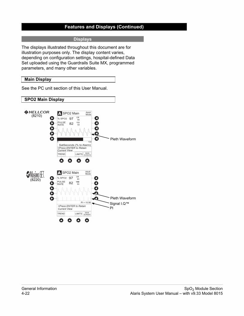
The displays illustrated throughout this document are for illustration purposes only. The display content varies, depending on configuration settings, hospital-defined Data Set uploaded using the Guardrails Suite MX, programmed parameters, and many other variables.
See the PC unit section of this User Manual.
Features and Displays (Continued)
Displays
Main Display
SPO2 Main Display
AAdultMode
82
% SPO2 97Off
150
90
50
LIMITSTRENDMAIN
SCREEN
PULSERATE
SPO2 Main
SatSeconds (% to Alarm)
0 100
>Press ENTER to RetainCurrent View
(8210)
AAdultMode
82
% SPO2 97Off
150
90
50
LIMITSTRENDMAIN
SCREEN
PULSERATE
SPO2 Main
PI = 10.56
>Press ENTER to RetainCurrent View
Pleth Waveform
Pleth Waveform
Signal I.Q™PI
(8220)
General Information SpO2 Module Section4-22 Alaris System User Manual – with v9.33 Model 8015

Options
dult, Neonatal
1, 2, 3, Off
31 - 240 bpm
30 - 239 bpm
1 - 100%, Off
20 - 99%
Off
See the PC unit section of this User Manual for system configurable settings.
If the configuration settings need to be changed from the Factory default settings, refer to the applicable Technical Service Manual or contact CareFusion Technical Support for technical, troubleshooting, and preventive maintenance information.
With the Profiles feature enabled, the settings are configured independently for each Profile. A hospital-defined, best- practice Data Set must be uploaded to enable the Profiles feature. Date and Time is a system setting and is the same in all Profiles.
Configurable Settings
Models 8210 and 8220
Feature Default Setting
Limit Mode Adult A
Pulse Beep Volume 1
Pulse Rate Alarm Limit, High Adult Mode: 120 bpmNeonatal Mode: 200 bpm
Pulse Rate Alarm Limit, Low Adult Mode: 50 bpmNeonatal Mode: 100 bpm
SpO2 Alarm Limit, High Adult: OffNeonatal: 95% 2
SpO2 Alarm Limit, Low Adult: 90%Neonatal: 80%
Model 8210
Feature Default Setting Options
SatSeconds Off 10, 25, 50, 100 seconds;
SpO2 Module Section General InformationAlaris System User Manual – with v9.33 Model 8015 4-23

Options
, 12, 14, 16 seconds
mal, Maximum
nd low saturation and pulse rate, sensor attery conditions.
against harmful effects of dripping water
High - 240 bpm
1 - 100%
Operating Storage/Transport
525 - 4560 mmHg(700 - 6080 hPa)
375 - 760 mmHg(500 - 1013 hPa)
20 - 90%Noncondensing
5 - 85%Noncondensing
41 - 104°F(5 - 40°C)
-4 - 140°F(-20 - 60°C)
Configurable Settings (Continued)
Model 8220
Feature Default Setting
Saturation Averaging Time(display update period)
8 seconds 2, 4, 8, 10
Sensitivity Mode Normal Nor
Specifications and Symbols
Specifications
Models 8210 and 8220
Alarms: Audible and visual alarms for high acondition, system failure, and low b
Alarm Limits:
Dimensions: 3.3" W x 8.9" H x 5.5" D(8.4 cm W x 22.6 cm H x 14 cm D)
Environmental Conditions:
Fluid Ingress Protection: IPX1,the SpO2 module is protectedper IEC 60529
LowPulse Rate: 30 - 239 bpm 31
SpO2 20 - 99% 2
Symbol Meaning
Atmospheric Pressure
Relative Humidity(Avoid prolonged exposure to relative humidity >85%)
Temperature Range
General Information SpO2 Module Section4-24 Alaris System User Manual – with v9.33 Model 8015

)
nt proportional pulse amplitude strength.
00 - 1000 nm. Output power does not
Adult Neonate
20 - 250 bpm±3 digits
20 - 250 bpm±3 digits
70 - 100%±2 digits
70 - 100%±3 digits
on No Motion Resolution40 bpmediatrics,
s: ±5 digits
25 - 240 bpmAdults, Pediatrics, Neonates: ±3 digits
1 bpm
100%ediatrics,
s: ±3 digits
70 - 100%Adults, Pediatrics:
±2 digits;Neonates: ±3 digits
1% SpO2
Specifications and Symbols (Continued
Specifications (Continued)
Models 8210 and 8220
Mode of Operation: Continuous
Shock Protection: Type BF patient applied part
Weight: 2 lbs (0.91 kg)
Model 8210
Accuracy Tolerance:
Display Update Period: 2.25 seconds
Measurement Range: Perfusion: 0.03 - 20%Pulse Rate: 20 - 250 bpmSpO2: 1 - 100%
Pulse Amplitude Display: Visual indicators for pulse signals represe
Sensor: Emitted light wavelength range is within 5exceed 15 mw.
Model 8220
Accuracy and Motion Tolerance:
Low PerfusionPulse Rate 20 - 250 bpm
±3 digits
Functional Saturation 70 - 100%±2 digits
Low Perfusion MotiPulse Rate 25 - 240 bpm
Adults, Pediatrics, Neonates: ±3 digits
25 - 2Adults, PNeonate
Saturation 70 - 100%Adults, Pediatrics:
±2 digits;Neonates: ±3 digits
70 -Adults, PNeonate
SpO2 Module Section General InformationAlaris System User Manual – with v9.33 Model 8015 4-25

)
0 - 1000 nm. Output power does not
Specifications and Symbols (Continued
Specifications (Continued)
Model 8220
Display Update Period: Approximately 1 second.
Measurement Range: Perfusion: 0.02 - 20%Pulse Rate: 25 - 240 bpmSpO2: 1 - 100%
Pulse Amplitude Display: Proportional to height of I.Q. signal.
Sensor: Emitted light wavelength range is within 50exceed 1 mw.
NOTE:Wavelength range information can be especially useful to clinicians, for example, those performing photodynamic therapy.
General Information SpO2 Module Section4-26 Alaris System User Manual – with v9.33 Model 8015

)
Specifications and Symbols (Continued
Specifications (Continued)
NOTES: Specification applies to monitor performance. Adult specifications are shown for OXIMAX MAX-A and MAX-N
sensors. Neonate specifications are shown for OXIMAX MAX-N sensors. Saturation accuracy varies by sensor type.
Masimo Board performance has been validated for low perfusion accuracy in bench–top testing against a BIO-TEK simulator and a Masimo simulator.
Masimo Board performance has been validated for motion accuracy in human blood studies on healthy adult volunteers in induced hypoxia studies, while performing rubbing and tapping motions at 2 - 4 Hz at an amplitude of 1 - 2 cm and a nonrepetitive range of 70 - 100% SpO2 against a laboratory co–oximeter and ECG monitor. This variation equals plus or minus one standard deviation. Plus or minus one standard deviation encompasses 68% of the population.
Masimo Board performance with Masimo LNOP™ Neo and Neo Pt sensors has been validated for neonatal motion accuracy in human blood studies on neonates, while moving the neonate’s foot at 2 - 4 Hz at an amplitude of 1 - 2 cm against a laboratory co–oximeter and ECG monitor. This variation equals plus or minus one standard deviation. Plus or minus one standard deviation encompasses 68% of the population.
Masimo Board performance has been validated for no-motion accuracy in human blood studies on healthy adult volunteers in induced hypoxia studies, in the range of 70 - 100% SpO2 against a laboratory co–oximeter and ECG monitor. This variation equals plus or minus one standard deviation. Plus or minus one standard deviation encompasses 68% of the population.
SpO2 Module Section General InformationAlaris System User Manual – with v9.33 Model 8015 4-27

)
d lines through the symbol might .
xceeded alarm limit.
If the accuracy of any measurement does not seem reasonable, first check the patient’s vital signs by alternate means and then check the SpO2 module to ensure that it is functioning properly.
An inaccurate measurement can be caused by:
• Incorrect sensor application or use.
• Significant levels of dysfunctional hemoglobins (such as carboxyhemoglobin or methemoglobin).
• Intravascular dyes (such as indocyanine green or methylene blue).
• Exposure to excessive illumination; such as, a surgical lamp (especially one with a xenon light source), bilirubin lamp, fluorescent light, infrared heating lamp, or direct sunlight.
• Prolonged and/or excessive patient movement.
• Venous pulsations.
Specifications and Symbols (Continued
Symbols
See the PC unit section of this User Manual for system symbols.
Symbol Meaning
Silenced alarm. Note: When displayed, the dasheappear as solid lines due to the small display size
Is displayed in Trend Data screen to identify an e
Type BF patient applied part.
Measurement Accuracy
NOTE:Because the SpO2 module's measurements are statistically distributed, only about two-thirds of the SpO2 module measurements can be expected to fall within ±Arms of the value measured by a co-oximeter.
General Information SpO2 Module Section4-28 Alaris System User Manual – with v9.33 Model 8015

• Sensor placed on an extremity with a blood pressure cuff,
arterial catheter, intravascular line or other causes of insufficient perfusion.
• Nail irregularity, such as nail polish or fungus. Remove nail polish and/or move sensor to an unaffected site.
• Placement is too close to electrosurgery equipment.
• Defibrillation.
The loss of a pulse signal can occur in any of the following situations:
• The sensor is too tight.
• Exposure to excessive illumination; such as, a surgical lamp (especially one with a xenon light source), bilirubin lamp, fluorescent light, infrared heating lamp, or direct sunlight.
• The sensor placed on an extremity with a blood pressure cuff, arterial catheter, intravascular line, or other causes of insufficient perfusion.
• The patient has hypotension, severe vasoconstriction, severe anemia or hypothermia, is in cardiac arrest or is in shock.
• There is an arterial occlusion proximal to sensor.
• Placement is too close to electrosurgery equipment.
Measurement Accuracy (Continued)
NOTE: Exposure to excessive illumination can be corrected by
covering the sensor with a dark or opaque material.
SpO2 Module Section General InformationAlaris System User Manual – with v9.33 Model 8015 4-29

Y
T H I S P A G EI N T E N T I O N A L LL E F T B L A N K
General Information SpO2 Module Section4-30 Alaris System User Manual – with v9.33 Model 8015

Alaris System User Manual – with v9.33 Model 8015 Section 5
Alaris EtCO2 Module Model 8300
Alaris EtCO2 ModuleModel 8300
ALARM MONITOR STANDBY
CHANNELSELECT
MONITOR
CHANNELOFF
EtCO (mm Hg)2
RR (breaths/min)

T H I S P A G EI N T E N T I O N A L L Y
L E F T B L A N K

Getting StartedIntroduction............................................................................................................................................. 5-1Connect Microstream™ Disposable....................................................................................................... 5-2Attach Gas Scavenging System............................................................................................................. 5-4
ProgrammingMonitoring Mode..................................................................................................................................... 5-5
Set Alarm Limits ............................................................................................................................. 5-6Navigate Trend Data ...................................................................................................................... 5-8Navigate PCA/Alaris EtCO2 ModuleTrend Data............................................................................. 5-9Presilence Alarm ............................................................................................................................ 5-10
Channel Options..................................................................................................................................... 5-10Change Limit Mode ........................................................................................................................ 5-10Change Waveform Height .............................................................................................................. 5-11Change Waveform Time Scale....................................................................................................... 5-12
General Setup and OperationSystem Start-Up/Setup........................................................................................................................... 5-13
General InformationWarnings and Cautions.......................................................................................................................... 5-15
General........................................................................................................................................... 5-15Microstream Disposable ................................................................................................................. 5-15
Microstream Disposable......................................................................................................................... 5-16Features and Displays............................................................................................................................ 5-17
Features and Definitions................................................................................................................. 5-17Operating Features, Controls, Indicators........................................................................................ 5-18Displays .......................................................................................................................................... 5-19
Configurable Settings............................................................................................................................. 5-19Specifications and Symbols ................................................................................................................... 5-20
Specifications ................................................................................................................................. 5-20Symbols.......................................................................................................................................... 5-23
Measurement Accuracy.......................................................................................................................... 5-24Waveform Analysis................................................................................................................................. 5-27Principle of Operation............................................................................................................................. 5-29
Table of Contents
EtCO2 Module Section Table of ContentsAlaris System User Manual – with v9.33 Model 8015 5-iii

T H I S P A G EI N T E N T I O N A L L Y
L E F T B L A N K
EtCO2 Module Section5-iv Alaris System User Manual – with v9.33 Model 8015

Getting Started
Read all instructions, for both the EtCO2 module and PC unit, before using the Alaris System.
WARNING
This section of the User Manual provides EtCO2 module (Model 8300) instructions and information. It is used in conjunction with:
• EtCO2 module Technical Service Manual
• Monitor Accessory Compatibility AlarisTM EtCO2 Module 8300 Series
• Covidien’s Microstream™ disposable instructions• PC unit section of this User Manual• System Maintenance software (and its instructions) for
Alaris System check-in, maintenance, and wireless configuration
The EtCO2 module is a capnograph indicated for continuous, noninvasive monitoring of end tidal carbon dioxide (EtCO2), fractional inspired carbon dioxide (FiCO2) and respiratory rate (RR). The end-tidal gas reading is calculated as a maximum value. The recommended setting and factory default is a 20 second window. The window defines the maximum measured EtCO2 and the minimum measure FiCO2.
The EtCO2 module and disposables are indicated for use with intubated and nonintubated adult, pediatric and neonatal patients. It is not intended for direct connection to ventilator or breathing systems. Only one EtCO2 module can be connected to the Alaris System.
The EtCO2 module is used with Covidien’s patented Microstream Disposables/circuits for sidestream capnography. The Microstream EtCO2 sampling lines deliver a sample of the inhaled and exhaled gases from direct contact to the patient via an oral/nasal cannula into the monitor for CO2 measurement.
Microstream Disposable: See "General Information" for "Microstream Disposable" Information.
Alarms and Messages: See "Troubleshooting and Maintenance" for module-specific alarms and messages.
Contraindications: None known.
Electromagnetic Environment: See "Appendix" section of this User Manual ("Regulations and Standards," "Compliance").
Introduction
EtCO2 Module Section Getting StartedAlaris System User Manual – with v9.33 Model 8015 5-1

Closed Position
Open Position
t
Use only Microstream Disposables. Use of a disposable other than those specified can cause improper EtCO2 module performance, resulting in inaccurate readings.
WARNING
1. Open gas inlet/outlet door by turning door
counterclockwise until gas inlet is clearly visible. Hold in open position.
Gas inlet is located on lower left corner of instrument and is marked with a gas inlet symbol ( ).
2. Connect Microstream Disposable:
a. Press brightly colored end of disposable into gas inlet.
b. Turn it clockwise until tightly secured to EtCO2 module.
Connect Microstream™ Disposable
Gas Inle
Getting Started EtCO2 Module Section5-2 Alaris System User Manual – with v9.33 Model 8015

ed)
3. Release door.
4. Connect Microstream Disposable to patient. Connection site and manner are dependent on patient intubation status and type of Microstream Disposable being used (refer to disposable's User Manual).
Connect Microstream Disposable (Continu
NOTE:The Covidien Disposable may be used with 5 liters of oxygen with a nasal cannula. This disposable is not intended to be used with high flow oxygen through a nasal cannula. The use of a mask with high flow oxygen is recommended. Two nasal cannulas should not be used at one time.
EtCO2 Module Section Getting StartedAlaris System User Manual – with v9.33 Model 8015 5-3

There is a risk of patient cross-infection if the sampled gas is returned to the breathing system.
WARNING
g
In the presence of high oxygen or anesthesia concentrations, it might be necessary to connect a gas scavenging system to the EtCO2 module.
1. Open gas inlet/outlet door by turning door counterclockwise until gas outlet is clearly visible. Hold in open position.
Gas outlet is located on lower right corner of instrument and is marked with a gas outlet symbol ( ).
2. Secure gas scavenger system tubing to EtCO2 module by firmly pushing tubing into fitting on gas outlet.
3. Release door.
Attach Gas Scavenging System
Gas Scavenger System Tubin
Getting Started EtCO2 Module Section5-4 Alaris System User Manual – with v9.33 Model 8015

Programming
CHANNELSELECT
MONITOR
CHANNELOFF
EtCO (mm Hg)2
RR (breaths/min)
Display references throughout this procedure are for illustration purposes only.
See "General Information," "Features and Displays" and PC unit section of this User Manual for information about:
• Displays
• Operating Features, Controls, Indicators
1. Perform following steps (see PC unit section of this User Manual, "General Setup and Operation," "Start-Up"):
a. Power on system.
b. Choose Yes or No to New Patient?.
c. Confirm current Profile or select a new Profile.
d. Enter patient identifier, if required.
2. Connect Microstream Disposable (see "Getting Started").
3. Press CHANNEL SELECT key.
SENSOR WARMING and then SEARCHING appear in Channel Message display until EtCO2 and respiratory rate readings stabilize (up to 60 seconds).
4. Alarm limits:
• To change settings, see "Set Alarm Limits" procedure.
Monitoring Mode
EtCO2 Module Section ProgrammingAlaris System User Manual – with v9.33 Model 8015 5-5

AAdultMode
13
ETCO2 34
LIMITSTRENDMAIN
SCREEN
RR
ETCO2 Main
mmHg
breaths/min
mmHg
60
25
10
5
>Press ENTER to RetainCurrent View
Time (sec)0 5421
80
0
40
2020
60
AAdultMode
13
ETCO2 34
LIMITSTRENDMAIN
SCREEN
RR
ETCO2 Main
mmHg
breaths/min
mmHg
60
25
10
5
>Press ENTER to RetainCurrent View
Time (sec)0 5421
80
0
40
2020
60
• To accept settings and begin monitoring, press ENTER
key.
ETCO2 Main screen displays following information:
◦ Capnography waveform (scale adjustable).
◦ EtCO2 value, as well as minimum and maximum EtCO2 alarm limits.
◦ Limit Mode (Adult or Neonatal).
◦ Respiratory rate (RR, breaths/min), as well as minimum and maximum RR alarm limits.
1. Press LIMITS soft key.
2. To change a limit setting, press soft key next to applicable parameter.
3. Enter a numeric value for selected alarm limit.
Monitoring Mode (Continued)
Set Alarm Limits
NOTE: PC unit display response time is approximately ½ second
longer than the EtCO2 module response time.
Programming EtCO2 Module Section5-6 Alaris System User Manual – with v9.33 Model 8015

A
ETCO2LOW 35
_ 40
CONFIRM
AdultModeAlarm Limits
25
5
RRHIGH
RRLOW
10NOBREATH
mmHg
mmHg
breaths/min
breaths/min
seconds
FICO2LIMIT
FiCO2 High : 10 mmHg
ETCO2HIGH
>Press CONFIRM toApply Changes
4. To move to next limit, press ENTER key.
5. To confirm alarm settings and return to ETCO2 Main display, press CONFIRM soft key.
6. To return to Main Display, press MAIN SCREEN soft key.
Monitoring Mode (Continued)
EtCO2 Module Section ProgrammingAlaris System User Manual – with v9.33 Model 8015 5-7

A
>Press UP/DOWN Keysto Move Cursor.
PAGEDOWNZOOM ETCO2
MAIN
ZOOM: 60 5 minutes
TIME
RRETCO2AVG
MINMAX
AVGMINMAX
2001-07-06
21:28
20:58
20:28
22:58 40 3847
41 3445
---
393744
13 1126
11 1014
---
121114
22:28 40 4439
12 16
21:58 41 3945 13 11
20
1120
Trend DataAdult Mode
09:00
30
PAGEUP
Fi
Fi
SILENCE
OPTIONS
147
CLEAR
2580
369 ENTER
CANCEL
SYSTEMON
PAGEUP
A
>Press UP/DOWN Keysto Move Cursor.
PAGEDOWNZOOM ETCO2
MAIN
ZOOM: 60 5 minutes
TIME
RRETCO2AVG
MINMAX
AVGMINMAX
2001-07-06
21:28
20:58
20:28
41 3445
---
393744
11 1014
---
121114
22:28 40 4439
12 1611
21:58 41 3945 13 20
1120
Trend DataAdult Mode
09:00
30
19:58 393744 12
1114
Fi
Fi
1. To view Trend Data, press TREND soft key.
Following information is displayed:
• TIME period for data review.
• Average ETCO2 with high and low values.
• Average respiratory rate (RR) with high and low values.
• Alarm icon ( ) with Fi in TIME column to indicate high FiCO2 alarm limit has been exceeded.
• Alarm icon ( ) to indicate an alarm limit has been exceeded.
• Alarm icon ( ) in RR column to indicate a no breath ( ) alarm limit has been triggered.
• Dashes (---), if no EtCO2 or respiratory rate values are available for time period displayed.
Tabular information is not updated while Trend Data view is displayed. Tabular data is updated, using new trend data stored in EtCO2 module, after leaving Trend Data view. To view latest data, return to Trend Data view.
2. To navigate from page to page, press PAGE UP and PAGE DOWN soft keys.
3. To scroll data one row at a time, press or key.
4. To change TIME increments for data review, move cursor to desired time period and press ZOOM soft key.
• New time increments display.
• Each press of ZOOM soft key changes time increments.
Monitoring Mode (Continued)
Navigate Trend Data
Programming EtCO2 Module Section5-8 Alaris System User Manual – with v9.33 Model 8015

A
5 sec
Limit Mode: Adult
Channel Options
EXIT
Waveform height: 80 mmHg
Waveform time scale:
PCA/EtCO2 Trend data
>Select an Option orEXIT
A
>Press UP/DOWN Keysto Move Cursor.
PAGEDOWNZOOM
ZOOM: minutes
TIME
RRETCO2TOTAL
DOSE (mg) AVG AVG2003-06-06
08:03
08:04
08:05 ------ ---
120
08:01
08:02
560 30
ETCO2MAIN
Morphine1mg/mL
09:00
1
08:06
40
415.01
392
13
11
12
402.55 12
411.2 13
---
5. To return to ETCO2 Main display, press ETCO2 MAIN soft key.
6. To return to Main Display, press MAIN SCREEN soft key.
To access and view shared trend data when a PCA module is present, perform the following steps.
1. To view ETCO2 Main display, press CHANNEL SELECT key.
2. To access option to view trend data, press OPTIONS key.
3. To view Trend Data, press PCA/EtCO2 Trend data soft key.
Following information is displayed:
• TIME period for data review.
• Average ETCO2.
• Average respiratory rate (RR).
• Alarm icon ( ).
• TOTAL DOSE of medication infused through PCA module (includes Continuous Infusion, loading dose, bolus, and PCA dose).
4. See "Navigate Trend Data" procedure for instructions on how to:
• Navigate from page to page.
• Change TIME increments.
• Return to ETCO2 MAIN display.
• Return to Main Display.
Monitoring Mode (Continued)
Navigate Trend Data (Continued)
Navigate PCA/Alaris EtCO2 ModuleTrend Data
EtCO2 Module Section ProgrammingAlaris System User Manual – with v9.33 Model 8015 5-9

SILENCE
OPTIONS
147
CLEAR
2580
369 ENTER
CANCEL
SYSTEMON
SILENCE
OPTIONS
A
VOLUMEINFUSED
AUDIOADJUST
Midtown HospitalMed Surg
BETCO2
CANCELSILENCE
A
5 sec
Limit Mode: Adult
Channel Options
EXIT
Waveform height: 80 mmHg
Waveform time scale:
PCA/EtCO2 Trend data
>Select an Option orEXIT
1. To presilence alarm, press SILENCE key.
All monitoring alarms are silenced for 120 seconds and an Monitoring Alarm Silence symbol is displayed on the PC unit main screen. Subsequent infusion alarms are not silenced.
2. To cancel presilence alarm and return to alarmable mode:
• Press CANCEL SILENCE soft key.
The following procedure can be performed only when the Guardrails Suite MX is not enabled (Profile option not being used for programming).
1. Press Limit Mode soft key.
Monitoring Mode (Continued)
Presilence Alarm
Channel Options
Change Limit Mode
Programming EtCO2 Module Section5-10 Alaris System User Manual – with v9.33 Model 8015

AA
Adult
Neonatal
Limit Mode Setup
EXIT
>Select an Option orEXIT
A
5 sec
Limit Mode: Adult
Channel Options
EXIT
Waveform height: 80 mmHg
Waveform time scale:
PCA/EtCO2 Trend data
>Select an Option orEXIT
AA
60 mmHg
Waveform Height
EXIT
>Select an Option orEXIT
99 mmHg
2. To change Limit Mode Setup, press applicable soft key.OR
To leave Limit Mode Setup unchanged and return to ETCO2 Main display, press EXIT soft key.
1. Press Waveform height soft key.
2. To change Waveform Height, select applicable range limit.
• 60 mmHg: Displays a waveform for EtCO2 values within 0 – 60 mmHg range. If EtCO2 value exceeds that range, Waveform Out of Range; Adjust Scaling message is displayed until waveform falls back into range or 0 – 99 mmHg option is selected.
• 99 mmHg: Displays a waveform for full EtCO2 value range, 0 – 99 mmHg.
3. To return to ETCO2 Main display, press EXIT soft key.
Channel Options (Continued)
Change Limit Mode (Continued)
Change Waveform Height
EtCO2 Module Section ProgrammingAlaris System User Manual – with v9.33 Model 8015 5-11

A
5 sec
Limit Mode: Adult
Channel Options
EXIT
Waveform height: 80 mmHg
Waveform time scale:
PCA/EtCO2 Trend data
>Select an Option orEXIT
AA
10 sec
Waveform Time Scale
EXIT
>Select an Option orEXIT
5 sec
1. Press Waveform time scale soft key.
2. To change Waveform Time Scale, select applicable time scale.
OR
To leave Waveform Time Scale unchanged and return to ETCO2 Main display, press EXIT soft key.
Channel Options (Continued)
Change Waveform Time Scale
Programming EtCO2 Module Section5-12 Alaris System User Manual – with v9.33 Model 8015

ral Setup and Operation
See the PC unit section of this User Manual, "General Setup and Operation," for various system start-up and setup procedures.
Gene
System Start-Up/Setup
EtCO2 Module Section General Setup and OperationAlaris System User Manual – with v9.33 Model 8015 5-13

Y
T H I S P A G EI N T E N T I O N A L LL E F T B L A N K
General Setup and Operation EtCO2 Module Section5-14 Alaris System User Manual – with v9.33 Model 8015

General Information
• EtCO2 and respiratory rate readings can be affected by certain ambient environmental and patient conditions.
• The EtCO2 module is not to be used as an apnea monitor.
• The EtCO2 module is intended only as an adjunct in patient assessment. It must be used in conjunction with clinical signs and symptoms.
• If uncertain about measurement accuracy, assess patient’s condition and vital signs by alternate means, then ensure that EtCO2 module is functioning correctly.
• Do not lift the EtCO2 module by Microstream Disposable because it could disconnect from the instrument, causing it to drop on the patient. Do not place the EtCO2 module in any position that could cause it to fall onto the patient.
• Do not use the EtCO2 module or Microstream Disposable inside a hyperbaric chamber.
• Respond immediately to system alarms; patient monitoring can cease under certain alarm conditions.
• Do not use a connector or Microstream Disposable that appears damaged.
• The Microstream Disposable disconnect error message and associated alarm indicate the Microstream Disposable is disconnected. Check the Microstream Disposable connection and, if necessary, replace the Microstream Disposable.
• Use only Microstream Disposables. Use of a disposable other than those specified can cause improper EtCO2 module performance, resulting in inaccurate readings.
Warnings and Cautions
General
Microstream Disposable
WARNINGS
WARNINGS
EtCO2 Module Section General InformationAlaris System User Manual – with v9.33 Model 8015 5-15

• Before use, read Microstream Disposable User Manual, including all warnings, cautions, and instructions.
• Carefully locate the patient Microstream Disposable to reduce the possibility of patient entanglement or strangulation.
• Do not immerse or dampen the Microstream Disposable.• The Microstream Disposables are designed for single
patient use and are not to be reprocessed. Do not attempt to disinfect or flush the disposable as the EtCO2 module can be damaged.
When selecting a Microstream Disposable, consider the patient’s weight, condition, and intubation status. For more information on Microstream Disposables, contact Covidien at http://www.covidien.com/rms or 1-800-635-5267.
For a list of compatible disposables, refer to the Monitor Accessory Compatibility AlarisTM EtCO2 Module 8300 Series (provided separately).
Warnings and Cautions (Continued)
Microstream Disposable (Continued)
Microstream Disposable
WARNINGS
CAUTIONS
General Information EtCO2 Module Section5-16 Alaris System User Manual – with v9.33 Model 8015

nd definitions.
ition
ncentration throughout respiration.
cal values are displayed.
exhalation.
ration present during inhalation.
display either adult or neonatal Settings" for additional configurable
ables are available for neonatal, can be intubated or nonintubated.
ion rates, and No Breath time periods
r minute (breaths/minute).
ry rate. Display shows average, tions for time period displayed. Up to
Features and Displays
Features and Definitions
See the PC unit section of this User Manual for system features a
Feature DefinBPM Breaths per minute.
Capnography Waveform
Real-time graphical display of CO2 co
Data Display Waveforms, trended data, and numeri
EtCO2 CO2 concentration in mmHg at end of
FiCO2 Fractional-inspired CO2; CO2 concent
Limit Mode Configurable mode that can be set to monitoring mode. (See "Configurable features.)
Microstream Disposable
Covidien's line of Microstream Dispospediatric, and adult patients. Patients
Programmable Alarm Limits
Alarm limits for EtCO2, FiCO2, respiratare programmable.
Respiratory Rate Patient’s respiratory rate in breaths pe
Trend Data Tabular display of EtCO2 and respiratohigh, and low values, and alarm condi24 hours of data is stored.
EtCO2 Module Section General InformationAlaris System User Manual – with v9.33 Model 8015 5-17

dbylow)
Channel (module) Identification
Channel (module) Select Key: When pressed, selects corresponding module for patient monitoring setup.
Channel (module) Off Key: When pressed and held until a beep is heard, stops operation on that module, deselects that module, and if only that module had been operating, system powers down.Repeat for other operating modules to power off each module.
Gas Exhaust: Gas scavenging system connection
Monitor Key: When pressed, begins patient monitoring.
IUI Connector, Right
Features and Displays (Continued)
Operating Features, Controls, Indicators
Status Indicators
Alarm(red)
Monitoring(green)
Stan(yel
EtCO2 mmHg Display
Channel (module) Message Display
Module Release Latch: When pressed, allows module to be removed.
Respiratory Rate Display
IUI Connector, Left(not visible)
Microstream™ Disposable Connector (Gas Inlet)
Protective Door
General Information EtCO2 Module Section5-18 Alaris System User Manual – with v9.33 Model 8015

ons
mmHg
mmHg
mmHg
Neonatal
econds
The displays illustrated throughout this document are for illustration purposes only. The display content varies, depending on configuration settings, type of disposable in use, hospital-defined Data Set uploaded using the Guardrails Suite MX, programmed parameters, and many other variables.
See the PC unit section of this User Manual.
See the PC unit section of this User Manual for system configurable settings.
If the configuration settings need to be changed from the Factory default settings, refer to the applicable Technical Service Manual or contact CareFusion Technical Support, for technical, troubleshooting, and preventive maintenance information. Please consult the facility’s best practices guidelines on the preferred alarm settings for the monitoring of patients that are not continuously attended by a clinician.
With the Profiles feature enabled, the settings are configured independently for each Profile. A hospital-defined, best- practice Data Set must be uploaded to enable the Profiles feature. Date and Time is a system setting and is the same in all Profiles.Al
Features and Displays (Continued)
Displays
Main Display
Configurable Settings
Feature Default Setting OptiEtCO2 Alarm Limit, High Adult: 60 mmHg
Neonatal: 60 mmHg 5 - 99
EtCO2 Alarm Limit, Low Adult: 10 mmHgNeonatal: 10 mmHg 0 - 98
FiCO2 Alarm Limit, High Adult: 8 mmHgNeonatal: 8 mmHg 2 - 99
Limit Mode Adult Adult or
No Breath Alarm Adult: 30 secondsNeonatal: 20 seconds 10 - 60 s
EtCO2 Module Section General InformationAlaris System User Manual – with v9.33 Model 8015 5-19

ons
0 bpm
9 bpm
ained to within 4% of the values in the
mmHg or 2.5% (whichever is greater), has y specifications.
e of 0 - 150 bpm with following accuracy:
Accuracy
±2 mmHg of reading + 0.08% for every mmHg above 38 mmHg)
ates of up to 80 bpm. For breath y is 4 mmHg or ±12 % of reading O2 values exceeding 18 mmHg. nd is compliant with ISO specified accuracies for breath te, the Microstream FilterLine H be used. Above 55ºC module 2.5%, whichever is greater, has to the accuracy specifications.
Configurable Settings (Continued)
Feature Default Setting OptiRespiratory Rate Alarm Limit, High
Adult Mode: 35 bpmNeonatal Mode: 80 bpm 1 - 15
Respiratory Rate Alarm Limit, Low
Adult Mode: 6 bpmNeonatal Mode: 12 bpm 0 - 14
Specifications and Symbols
Specifications
Accuracy: EtCO2 readings:
The accuracy specification is maintpresence of interfering gases.
Above 55°C module temperature, ±1to be added to tolerance of accuracRespiration rate, measured in rang0 - 70 bpm: ±1 bpm71 - 120 bpm: ±2 bpm121 - 150 bpm: ±3 bpm
CO2 Partial Pressure(at sea level)0 - 38 mmHg39 - 99 mmHg ± (5%
1
NOTE: Accuracy applies for breath r
rates above 80 bpm, accuracwhichever is greater, for EtCThis is tested according to a80601-2-55. To achieve the rates above 60 breaths/minuSet for Infant/Neonatal musttemperature, ± 1mmHg or ± be added to the tolerance of
General Information EtCO2 Module Section5-20 Alaris System User Manual – with v9.33 Model 8015

)
ow EtCO2 and respiratory rate, high FiCO2, em failure, no breath, and low battery
tic barometric pressure compensation. ometric pressure for this device.
of CO2 in the range of 0 - 99 mmHg at sea ulated for all valid breaths.
Highg 5 - 99 mmHg
le 2 - 99 mmHg
Not Applicable
/min 1 - 150 breaths/min
perating Storage/Transport
80 - 4570 m50 - 15,000 ft)
-380 - 4570 m(-1250 - 15,000 ft)
- 4560 mmHg - 6080 hPa)
375 - 760 mmHg(500 - 1013 hPa)
20 - 90%ncondensing
5 - 85%Noncondensing
1 - 104°F(5 - 40°C)
-4 - 140°F(-20 - 60°C)
Specifications and Symbols (Continued
Specifications (Continued)
Alarm Limits:
Alarms: Audible and visual alarms for high and lMicrostream Disposable condition, systconditions.
Barometric Pressure: EtCO2 module is equipped with automaThere are no quantitative effects of bar
CO2 Range: Measures and reports partial pressureslevel. EtCO2 and FiCO2 values are calc
Dimensions: 3.3" W x 8.9" H x 5.5" D
(8.4 cm W x 22.6 cm H x 14 cm D)
Environmental Conditions:
Fluid Ingress Protection: IPX1, Drip Proof
LowEtCO2 0 - 98 mmH
FiCO2 Not Applicab
No Breath 10 - 60 sec
Respiration Rate 0 - 149 breaths
Symbol Meaning O
Altitude -3(-12
Atmospheric Pressure
525 (700
Relative Humidity(Avoid prolonged exposure to relative humidity >85%)
No
Temperature Range
4
EtCO2 Module Section General InformationAlaris System User Manual – with v9.33 Model 8015 5-21

)
ates of up to 80 bpm. For maintaining e 80 bpm, accuracy is 4 mmHg or ±12% of tCO2 values exceeding 18 mmHg. To eath rates above 60 bpm, Microstream ust be used.
een tested and were found to have no
ours
in
ds typical (includes rise time of 190 msec onds typical).tely ½ second longer than EtCO2 module
Specifications and Symbols (Continued
Specifications (Continued)
Frequency Response: EtCO2 accuracy applies for breath raccuracy for respiration rates abovreading, whichever is greater, for Eachieve specified accuracies for brneonatal airway adapter M1996A m
Gas Interference: Following liquid anesthetics have beffect:DesfluraneEnfluraneHalothaneIsofluraneSevoflurane
Internal Power Source: Operating time (fully charged): 5.5 h
Measurement Range: EtCO2: 0 - 99 mmHgFiCO2: 0 - 99 mmHgRespiratory Rate: 0 - 150 bpm
Mode of Operation: Continuous
Sampling Gas Flowrate: Nominally 50 mL/min -7.5 +15 mL/m
Shock Protection: Type BF patient applied part
System Response Time: EtCO2 module response: 2.9 seconmaximum and delay time of 2.7 secPC unit display response: approximaresponse
Warm-Up Time: 30 seconds typical
Waveform Sampling 20 samples/s
Weight: 2.5 lbs (0.91 kg)
NOTE:The periodic auto zero function compensates for drifts between components, changes in ambient temperature and barometric conditions. This automatic process eliminates variances that might otherwise cause measurement drift. Therefore the module does not exhibit drift.
General Information EtCO2 Module Section5-22 Alaris System User Manual – with v9.33 Model 8015

)
dashed lines through the symbol might
d alarm limit.
d no breath alarm limit.
See the PC unit section of this User Manual for system symbols.
Specifications and Symbols (Continued
Symbols
Symbol Meaning
Type BF patient applied part.
Gas inlet.
Gas outlet.
Monitoring alarm or presilence. Note: When displayed, theappear as solid lines due to the small display size.
Is displayed in Trend Data screen to identify an exceede
Is displayed in Trend Data screen to identify an exceede
Follow Instructions for Use
EtCO2 Module Section General InformationAlaris System User Manual – with v9.33 Model 8015 5-23

• If uncertain about measurement accuracy, assess patient’s condition and vital signs by alternate means, then ensure that EtCO2 module is functioning correctly.
• Leaks or internal venting of sampled gas can affect accuracy.
WARNINGS
The EtCO2 module has been designed and manufactured to exacting standards and should perform well within given environmental and performance standards. There are certain conditions under which an inaccurate measurement or the loss of respiratory rate signal can occur.
An inaccurate EtCO2 measurement can be caused by:
• Incorrect disposable application or use.
• Microstream Disposable disconnected or not securely connected to EtCO2 module.
• Airway connection clogged, twisted, or leaking.
• Placement too close to electrosurgery equipment.
• Mechanically ventilated patient breathes spontaneously.
Loss of a respiratory rate signal can occur in any of the following situations:
• Incorrect disposable application or use.
• Microstream Disposable disconnected or not securely connected to EtCO2 module.
• Airway connection clogged, twisted, or leaking.
• Patient not breathing.
• Placement too close to electrosurgery equipment.
Measurement Accuracy
General Information EtCO2 Module Section5-24 Alaris System User Manual – with v9.33 Model 8015

The following test method is used to determine the module’s rated respiration rate range and the corresponding effects of end-tidal gas readings accuracy as a function of respiratory rate:
• The system is set for operation.
• The power connection is verified.
• The module is connected to the PC and power supply.
• A scope is connected to the digital/analog multifunction I/O.
• A digital output scheduler software is opened on the PC.
• Gas connections are checked.
• The power connection is verified.
• The gas mixes cylinders are open, set on the required pressure, and their condition is verified.
• A BPM setting is selected.
• The module is connected to the gas tube.
• The module is disconnected.
Measurement Accuracy (continued)
Respiration Rate Test
NOTE:When CO2 waveforms are generated the CO2 reading line increases in height and then returns to the selected baseline rate (BPM).
EtCO2 Module Section General InformationAlaris System User Manual – with v9.33 Model 8015 5-25

Expected Results
±2mmHg/±1bpm
±2mmHg/±1bpm
ssure Accuracy
± 2 mmHg
± (5% of reading + 0.08 for every 1 mmHg above 38 mmHg)
***± (5% of reading + 0.08 for every 1 mmHg above 38 mmHg)
±2mmHg/±1bpm
±2mmHg/±2bpm
±4.1mmHg/±2bpm
±4.1mmHg/±3bpm
ssure Accuracy
± 2 mmHg
± (5% of reading + 0.08 for every 1 mmHg above 38 mmHg)
***± (5% of reading + 0.08 for every 1 mmHg above 38 mmHg)
Measurement Accuracy (continued)
Respiration Rate Test (continued)
Test Action
Measure Accuracy/RR Tolerance mmHg / bpm for Adult/Pediatric FilterLine Sets at respiration rates of 10, 40, and 60 bpm.
10 bpm
40 bpm
60 bpm
Measure CO2 (mmHg) / RR (bpm) for Adult/Pediatric FilterLine Sets at respiration rates of 10, 40, and 60 bpm.
CO2 Partial Pre
0-38 mmHg
39-99 mmHg
100-150 mmHg
Measure Accuracy/RR Tolerance mmHg / bpm for Infant/Neonatal FilterLine H Sets at respiration rates of 60, 80, 120 and 150 bpm.
60 bpm
80 bpm
120 bpm
150 bpm
Measure CO2 (mmHg) / RR (bpm) for Infant/Neonatal FilterLine H Sets at respiration rates of 60, 80, 120 and 150 bpm.
CO2 Partial Pre
0-38 mmHg
39-99 mmHg
100-150 mmHg
NOTE: At sea level. Accuracy applies for breath rates of up to 80 bpm. For breath
rates above 80 bpm, accuracy is 4 mmHg or ±12 % of reading whichever is greater, for EtCO2 values exceeding 18 mmHg.This is tested according to and is compliant with ISO 80601-2-55. To achieve the specified accuracies for breath rates above 60 breaths/minute, the Microstream FilterLine H Set for Infant/Neonatal must be used.
General Information EtCO2 Module Section5-26 Alaris System User Manual – with v9.33 Model 8015

as a waveform. The following graph mHg). In the event the EtCO2 value
l be clipped. Numerical EtCO2 values
DDDD
A - B: baseline period of no CO2; end of inhalationB - C: rapid rise in CO2C - D: alveolar plateauD: end of expiration; end tidal CO2 (EtCO2)D - E: inhalation
Waveform Analysis
The EtCO2 module provides the option to display EtCO2 readingsis an example of a normal waveform (normal ventilation, 35 - 45 mis above the waveform display range, the top of the waveform wilcontinue to be displayed on both the EtCO2 module and PC unit.
EtCO2 Module Section General InformationAlaris System User Manual – with v9.33 Model 8015 5-27

Waveforms can be used to troubleshoot problems with equipment or monitor configuration, as well as to monitor a patient’s clinical status. The following graphs are examples of common problems identifiable through waveform analysis. These are examples only and do not represent all potential abnormal waveforms. Abnormal waveforms are not always associated with alarms.
Waveform Analysis (Continued)
Waveform Possible Causes
Hypoventilation
• overmedication
Hyperventilation
• respiratory distress
Partial Airway Obstruction
• relaxation of upper airway• head position
Hypoventilation with Shallow Breathing
• medication effect• low tidal volume
No Breath Detected
• apnea• very shallow breathing• overmedication• displaced cannula
General Information EtCO2 Module Section5-28 Alaris System User Manual – with v9.33 Model 8015
The EtCO2 module uses Covidien's patented Microstream nondispersive infrared (NDIR) spectroscopy to continuously measure the amount of CO2 during every breath, the amount of CO2 present at the end of exhalation (EtCO2) and during inhalation (FiCO2), and the Respiratory Rate. The EtCO2 module is a side stream capnograph.
The Microstream Disposables deliver a sample of the inhaled and exhaled gases from the ventilator disposable or directly from the patient (via an oral/nasal cannula) into the monitor for CO2 measurement. Moisture and patient secretions are extracted from the sample by the Microstream inline filter while maintaining the shape of the CO2 waveform.
The 50 mL/min sampling gas flowrate reduces liquid and secretion accumulation, decreasing the risk of obstruction in the sample pathway in humid ICU environments. The small sample size eliminates the need for water traps and prevents excess fluid accumulation.
The EtCO2 module draws a gas sample through a microsample cell (15 microliters). This extremely small volume is quickly flushed, allowing for a rise time of approximately 190 ms and accurate CO2 readings, even at high respiration rates.
The Microbeam IR source illuminates the microsample cell and the reference channel. This proprietary IR light source generates only the specific wavelengths characteristic of the CO2 absorption spectrum. The IR light that passes through the microsample cell and the IR light that passes through the reference channel are measured by IR detectors.
The microcomputer in the EtCO2 module calculates the CO2 concentration by comparing the signals from both channels.
No operator intervention is required for routine moisture or condensate.
All Microstream Disposables contain an inline hydrophobic filter to extract condensate and/or patient secretions while maintaining measurement and waveform integrity. For humid conditions within the operating parameters of the EtCO2 module and Microstream Disposables, humidity has no quantitative effect on the CO2 concentration, given the small 50 mL/min sample size rate. In high humidity environments or extended monitoring periods (24 - 72 hours), only Microstream Disposables designed for those instances should be
Principle of Operation
EtCO2 Module Section General InformationAlaris System User Manual – with v9.33 Model 8015 5-29

used. In the event of humidity or condensate outside the EtCO2 module’s operating specifications, the EtCO2 module will present a "Remove Blocked Disposable" message.
Due to the relatively small sampling size needed for EtCO2 readings, partial pressure does not affect the ability of the EtCO2 module to measure EtCO2, as long as the 50 mL/min rate can be achieved.
Microstream Disposables are single-use, disposables which must be changed with each use. The manufacturer’s sample flow, 50 mL/min, does not affect the disposable’s life; however, humidity and specific patient conditions can shorten the effective life of the disposables. Microstream Disposables are rated for up to 24 hours and 72 hours use, depending on the specific Microstream Disposable.
The EtCO2 module provides readings in compliance with BTPS (body temperature, pressure, saturation) standards. There is no affect on accuracy due to cyclic pressure up to 10 kPa.
Principle of Operation (Continued)
NOTE: BTPS (body temperature, pressure, saturation assumed 37°C,
47 mmHg) calculations are made according to:PCO2 = FCO2 x (Pb - 47)Where:
FCO2 is fractional concentration of CO2 in dry gas andFCO2 = % CO2/100.Pb is ambient pressure.PCO2 is partial pressure of CO2 at BTPS.
General Information EtCO2 Module Section5-30 Alaris System User Manual – with v9.33 Model 8015

EtCO2 Module Section General InformationAlaris System User Manual – with v9.33 Model 8015 5-31

General Information EtCO2 Module Section5-32 Alaris System User Manual – with v9.33 Model 8015
T H I S P A G EI N T E N T I O N A L L Y
L E F T B L A N K

Alaris System User Manual – with v9.33 Model 8015 Section 6
Alaris Auto-ID ModuleModel 8600
READY
SCANCANCEL

T H I S P A G EI N T E N T I O N A L L Y
L E F T B L A N K

Getting StartedIntroduction............................................................................................................................................. 6-1
ProgrammingPatient Identification............................................................................................................................... 6-3
New Patient .................................................................................................................................... 6-3While Infusion is in Progress .......................................................................................................... 6-4
Authorized User Mode* .......................................................................................................................... 6-6Primary Infusion ..................................................................................................................................... 6-8Secondary Infusion................................................................................................................................. 6-9
General Setup and OperationSystem Start-Up/Setup........................................................................................................................... 6-11
General InformationWarnings and Cautions.......................................................................................................................... 6-13Handheld Scanners................................................................................................................................ 6-13Features ................................................................................................................................................. 6-14
Features and Definitions................................................................................................................. 6-14Operating Features, Controls, Indicators........................................................................................ 6-15
Configurable Settings............................................................................................................................. 6-16Specifications and Symbols ................................................................................................................... 6-16
Specifications ................................................................................................................................. 6-16Symbolology ................................................................................................................................... 6-17Symbols.......................................................................................................................................... 6-17
Troubleshooting and MaintenanceErrors and Messages ............................................................................................................................. 6-18
Errors.............................................................................................................................................. 6-18Messages ....................................................................................................................................... 6-19
Table of Contents
Auto-ID Module Section Table of ContentsAlaris System User Manual – with v9.33 Model 8015 6-iii

T H I S P A G EI N T E N T I O N A L L Y
L E F T B L A N K
Auto-ID Module Section6-iv Alaris System User Manual – with v9.33 Model 8015

Getting Started
Read all instructions, for both the Auto-ID module and PC unit, before using the Alaris System.
WARNING
This section of the User Manual provides Auto-ID module (Model 8600) instructions and information. It is used in conjunction with:
• Auto-ID Label Specification• Auto-ID Module Technical Service Manual• Module-specific chapters of this User Manual• PC unit section of this User Manual• System Maintenance software (and its instructions) for Alaris
System check-in, maintenance, and wireless configuration
The addition of the Auto-ID module to the Alaris System with Guardrails Suite MX combines dose limit technology and barcode technology to enhance medication safety. The Auto-ID module contains an internal barcode image scanner and supports an optional handheld scanner supplied by CareFusion. Scanning a barcoded clinician ID and/or a barcoded patient identification band supports verification of the correct patient and associates the CQI event logs with the clinician and/or patient. In addition, using the scanner allows an IV solution drug and concentration to be automatically selected from the Drug Library. Scanned solution containers can be used for Pump, Syringe and PCA infusions. Only one Auto-ID module can be connected to the Alaris System but it can be added as a fifth module.
The Alaris System with the Auto-ID module is intended to provide trained healthcare caregivers a way to automate infusion parameter input, thereby decreasing the number of manual steps necessary to enter infusion data. All data entry and infusion parameter validation is performed by the trained healthcare professional according to a physician’s order.
Electromagnetic Environment: See "Appendix" section of this User Manual ("Regulations and Standards," "Compliance").
Introduction
Auto-ID Module Section Getting StartedAlaris System User Manual – with v9.33 Model 8015 6-1

Y
T H I S P A G EI N T E N T I O N A L LL E F T B L A N K
Getting Started Auto-ID Module Section6-2 Alaris System User Manual – with v9.33 Model 8015

Programming
Use only the handheld external scanner supplied by CareFusion. Using other accessories can result in increased emissions or decreased immunity of the Alaris System.
WARNING
READY
SCANCANCEL
-to-scan cator
Associating the PC unit with a patient provides a means of identifying the module(s) that will deliver IV medications to that particular patient.
To associate the PC unit with a new patient ID:
1. Attach handheld scanner to connection port on Auto-ID module. Ensure a secure circuit connection.
2. Power on PC unit.
3. To select New Patient?, press Yes soft key.
4. To accept current Profile, press Yes soft key.
OR
To proceed to Profile selection screen, press No soft key.
5. To accept Profile selection, press CONFIRM soft key.
• Patient ID Entry screen appears.
• Green READY indicator illuminates, indicating system is ready to scan.
Patient Identification
New Patient
Readyindi
Auto-ID Module Section ProgrammingAlaris System User Manual – with v9.33 Model 8015 6-3

Scan
Scan Trigger
1st Generation Scanner
2nd Generation Scanner
• CLASS 1 LED PRODUCT: Do not stare into the beam or allow beam to strike patient's face.
• Always verify that information displayed on the PC unit matches scanned data.
CAUTION
6. To scan barcode on patient identification band, press scan trigger on handheld scanner.
• If scan is successful, an audible tone sounds and patient ID appears on Main Display.
• If Profile is configured in Authorized User Mode, PANEL LOCKED screen appears.
• When a questionable barcode is scanned at main screen and panel is unlocked, a prompt to confirm type of barcode scanned appears. This occurs whether Authorized User Mode is enabled or disabled.
To unlock panel, clinician's ID must be scanned.
To associate the PC unit with a patient ID when patient ID screen is not shown:
1. Attach handheld scanner to connection port on Auto-ID module. Ensure a secure circuit connection.
The green READY indicator illuminates, indicating the system is ready to scan.
Patient Identification (Continued)
New Patient (Continued)
While Infusion is in Progress
NOTES: Automatic display of Patient ID Entry screen should be
enabled in the System Configuration settings. If the patient ID is not entered at this time, it can still be
entered later. Patient ID can be entered manually using the PC unit keypad
(see PC unit section of this User Manual).
NOTE:There is a prompt to accept or decline the change of patient ID if it is different from the patient ID already associated to the PC unit.
Programming Auto-ID Module Section6-4 Alaris System User Manual – with v9.33 Model 8015

• CLASS 1 LED PRODUCT: Do not stare into the beam or allow beam to strike patient's face.
• Always verify that information displayed on the PC unit matches scanned data.
CAUTIONS
2. To scan barcode on patient identification band, press scan trigger on handheld scanner.
If scan is successful, an audible tone sounds and patient ID appears on Main Display.
Patient Identification (Continued)
New Patient (Continued)
NOTE: Patient ID can be entered manually using the PC unit keypad
(see PC unit section of this User Manual).
NOTE:There is a prompt to accept or decline the change of patient ID if it is different from the patient ID already associated to the PC unit.
Auto-ID Module Section ProgrammingAlaris System User Manual – with v9.33 Model 8015 6-5

Authorized User Mode is a feature that:
• Combines PC unit tamper resist feature with Auto-ID application.
• Is designed to ensure that only clinicians with a barcode on their ID badge can program Alaris System.
• Is available only if it is enabled in selected Profile and there is an Alaris Auto-ID module attached.
When this feature is enabled, the PC unit automatically enables the tamper resist mode upon power on and 5 minutes after programming is completed. If the system is configured to do so, the Authorized User Mode can be disabled without scanning a clinician's ID; press and hold the Tamper Resist Switch (on back of PC unit) for 3 - 4 seconds.
To unlock the keypad, the user must scan their ID badge or use the OPTIONS menu to manually input their ID number. When a questionable barcode is scanned at the main screen and the keypad is unlocked, a prompt to confirm the type of barcode scanned appears. This occurs whether the Authorized User Mode is enabled or disabled.
To use Alaris System with Authorized User Mode enabled:
1. Power on system and associate patient ID (see "Patient Identification" procedure).
Upon successful entry of patient ID, PC unit automatically enables tamper resist feature.
2. To disable tamper resist, press SCAN/CANCEL key on the Auto-ID module or the SCAN trigger on handheld scanner and scan clinician ID badge.
In a very low battery condition, with less than 5 minutes of battery time remaining, scanner is disabled. In this situation, disable tamper resist by pressing Tamper Resist Switch on back of PC unit for approximately 2 seconds.
Authorized User Mode*
Programming Auto-ID Module Section6-6 Alaris System User Manual – with v9.33 Model 8015

3. Program infusion.
When no keys have been pressed on PC unit for a 5-minute period, tamper resist mode is automatically enabled.
Authorized User Mode* (Continued)
NOTE:There are three events that make the Authorized User Mode unavailable: a channel error, system error, or a discharged battery alarm.
*
Auto-ID Module Section ProgrammingAlaris System User Manual – with v9.33 Model 8015 6-7

• CLASS 1 LED PRODUCT: Do not stare into the beam or allow beam to strike patient's face.
• Always verify that information displayed on the PC unit matches scanned data.
CAUTIONS
Using the Auto-ID module to scan IV medication containers provides the ability to select the correct medication and Drug Amount/Diluent Volume from the drug library, and enhances safety through the use of the Guardrails Suite MX. It compares the medication identifier from the IV container barcode with the medication identifier from the Drug Library. If the patient ID is in the IV container barcode, the system also compares the patient identifier in the barcode with the patient identifier in the PC unit.
When the green READY indicator illuminates, the system is ready to scan.
1. To scan barcode on IV container, press the SCAN/CANCEL key on Alaris Auto-ID module or scan trigger on handheld scanner.
The PC unit displays the scanned medication/fluid information.
2. Press CHANNEL SELECT key on appropriate module.
Alaris System determines if module selected is appropriate for scanned medication type. If selection is not appropriate, a pop-up message is displayed with a request to CONFIRM message, and scan is cancelled.
3. Program infusion (see applicable module-specific section of this User Manual).
Primary Infusion
NOTE:There is a prompt to accept or decline the change of patient ID if it is different from the patient ID already associated to the PC unit. Auto-ID green READY scan light on the Auto ID module illuminates, indicating the screens that allow scanning. The green ready scan light does not illuminate when the programming steps have passed the point of being able to scan the medication.
Programming Auto-ID Module Section6-8 Alaris System User Manual – with v9.33 Model 8015

• CLASS 1 LED PRODUCT: Do not stare into the beam or allow beam to strike patient's face.
• Always verify that information displayed on the PC unit matches scanned data.
CAUTIONS
A subsequent primary infusion may be scanned with the Pump module running if the following criteria match between the scanned label and the running infusion:
• Drug or Fluid name (Alias or NDC)• Drug Amount• Drug Amount Units• Diluent Volume
To start a secondary infusion while a primary infusion is in progress:
1. To scan barcode on IV container, press SCAN/CANCEL key on Alaris Auto-ID module or scan trigger on handheld scanner.
The PC unit displays the scanned medication/fluid information.
2. Press CHANNEL SELECT key on appropriate module.
Primary infusion parameters display.
3. Press SECONDARY soft key.
4. Program secondary infusion (see Pump module section of this User Manual).
Subsequent Primary Infusion
Secondary Infusion
Auto-ID Module Section ProgrammingAlaris System User Manual – with v9.33 Model 8015 6-9

Y
T H I S P A G EI N T E N T I O N A L LL E F T B L A N K
Programming Auto-ID Module Section6-10 Alaris System User Manual – with v9.33 Model 8015

al Setup and Operation
See the PC unit section of this User Manual, "General Setup and Operation", for various system start-up and setup procedures.
Gener
System Start-Up/Setup
Auto-ID Module Section General Setup and OperationAlaris System User Manual – with v9.33 Model 8015 6-11

Y
T H I S P A G EI N T E N T I O N A L LL E F T B L A N K
General Setup and Operation Auto-ID Module Section6-12 Alaris System User Manual – with v9.33 Model 8015

General Information
• Do not open the handheld scanner case. If the case is opened, an electrical shock hazard and possible exposure to potentially hazardous LED light exists which can result in serious personal injury and product damage.
• Use only the handheld external scanner supplied by CareFusion. Using other accessories can result in increased emissions or decreased immunity of the Alaris System.
WARNINGS
CLASS 1 LED PRODUCT: Do not stare into the beam or allow beam to strike patient's face.
CAUTION
• Do not open the handheld scanner case. If the case is opened, an electrical shock hazard and possible exposure to potentially hazardous LED light exists which can result in serious personal injury and product damage.
• Carefully locate the handheld scanner to reduce the possibility of patient entanglement or strangulation.
• Use only the handheld external scanner supplied by CareFusion. Using other accessories can result in increased emissions or decreased immunity of the Alaris System.
Class 1 LED devices are safe under reasonably foreseeable conditions of operation, including the use of optical instruments for intrabeam viewing. To avoid potential harm, avoid looking into the beam or allowing the beam to strike the patient's face.
The handheld external scanners supplied by CareFusion are the only handheld scanners approved for use with the Auto-ID module.
Warnings and Cautions
Handheld Scanners
WARNINGS
CAUTION
1st Generation 2nd GenerationScanner Scanner
Auto-ID Module Section General InformationAlaris System User Manual – with v9.33 Model 8015 6-13

nd definitions.
efinition
of a successful scan.
for automatic identification. D) is the broad term given to a lp machines identify objects and data capture. These technologies voice recognition, some biometric nal scans), optical character
a digital camera to read barcodes. barcodes.
nd of IV containers that have already
y of high intensity LEDs to illuminate tions”).
and is more easily read by Auto-ID and drug ID can be in same
Features
Features and Definitions
See the PC unit section of this User Manual for system features a
Feature D
Audible Scan Indicator Provides audible confirmation
Barcode A machine-readable label usedAutomatic identification (Auto-Ihost of technologies used to heis often coupled with automaticinclude barcodes, smart cards,technologies (for example, retirecognition, and others.
Built-In Optical Scan Engine Employs technology similar to Allows use of two-dimensional
Handheld Scanner with Optical Scan Engine
Allows scanning of patient ID, abeen hung on IV pole.
Light Emitting Diode (LED) Barcode scanner uses an arrabarcode image (see “Specifica
Two-Dimensional Barcode Can contain more information module; for example, patient IDbarcode.
General Information Auto-ID Module Section6-14 Alaris System User Manual – with v9.33 Model 8015

READY Indicator: Green LED illuminates to provide visual confirmation that module or handheld scanner is ready to scan
SCAN/CANCEL Key: When initially pressed, scanning is initiated by embedded scanner. Subsequent press cancels scan.
Handheld external scanner connection port
Image Scanning Window
IUI Connector, Right
(not visible)
Features (Continued)
Operating Features, Controls, Indicators
Module Release Latch: When pressed, allows module to be removed.
IUI Connector, Left
Auto-ID Module Section General InformationAlaris System User Manual – with v9.33 Model 8015 6-15

canner
W average radiant powerW average radiant power
perating Storage/Transport
- 4560 mmHg - 6080 hPa)
375 - 760 mmHg(500 - 1013 hPa)
20 - 90%ncondensing
5 - 85%Noncondensing
1 - 104°F(5 - 40°C)
-4 - 140°F(-20 - 60°C)
See the PC unit section of this User Manual for system configurable settings
If the configuration settings need to be changed from the Factory default settings, refer to the applicable Technical Service Manual or contact CareFusion Technical Support, for technical, troubleshooting, and preventive maintenance information.
With the Profiles feature enabled, the settings are configured independently for each Profile. A hospital-defined, best- practice Data Set must be uploaded to enable the Profiles feature. Date and Time is a system setting and is the same in all Profiles.l
Configurable Settings
Specifications and Symbols
Specifications
Auto-ID Module and Handheld S
Environmental Conditions:
LED Light: Class 1 LED product.Aiming LED: 523 nm, cw, 0.412 mIllumination LED: 635 nm, cw, 2.226 m
Alaris Auto-ID Module
Dimensions: 2.0" W x 7.25" H x 5.0" D(5.1 cm W x 19.8 cm H x 12.7 cm D)
Symbols Meaning O
Atmospheric Pressure
525 (700
Relative Humidity(Avoid prolonged exposure to relative humidity >85%)
No
Temperature Range
4
General Information Auto-ID Module Section6-16 Alaris System User Manual – with v9.33 Model 8015

)
can be used to scan a patient's ID, handheld scanner read printed cified by ANSI X 3.182, CEN EN 1635, applied barcodes on IV bags are ble with the Auto-ID module and detailed barcode label information.
Specifications and Symbols (Continued
Specifications (Continued)
Alaris Auto-ID Module
Fluid Ingress Protection: IPX1, Drip Proof
Mode of Operation: Continuous
Shock Protection: Type BF patient applied part.
Weight: 1 ±0.1 lbs (436.5 ±43.65 g)
Handheld Scanner
Dimensions: 3.25" W x 7.25" H x 4.25" L(8.3 cm W x 18.4 cm H x 10.8 cm L)
Housing: UL 94V0 flammability rating
Weight: 6.5 oz (178 g)
Symbolology
The Auto-ID module supports an optional handheld scanner that medication labels and clinician badges. The Auto-ID module and barcodes which are within the barcode print quality guidelines speand ISO/IEC 15416 international standards. Some manufacturer-not compliant with these quality standards and might not be readahandheld scanner. Refer to the Auto-ID Label Guidelines for more
Symbols
See the PC unit section of this User Manual for system symbols.
Symbol Meaning
Input. Handheld connection point.
Type BF patient applied part.
Auto-ID Module Section General InformationAlaris System User Manual – with v9.33 Model 8015 6-17

oting and Maintenance
Response
Ensure that ID label is legible. Enter ID manually.
Ensure that ID label is legible. Enter ID manually.
r
Ensure that Profile is enabled. Ensure that ID label is legible. Inform pharmacy of problem.
r Ensure that ID label is legible. Inform pharmacy of problem.
Alarms and Alerts: See “Appendix A” "Troubleshooting and Maintenance" for the following system references:
Alarms and alertsAudio CharacteristicsDefinitionsDisplay ColorRadio Frequency Note
Troublesho
Errors and Messages
Errors
Error Meaning
Clinician ID is invalid Clinician ID is not recognized.
Patient ID is invalid Patient ID is not recognized.
Scanned label is invalid Profile feature might be disabled.Barcode might not be readable oa supported symbology.
Scanned medication label is invalid Barcode might not be readable oa supported symbology.
Troubleshooting and Maintenance Auto-ID Module Section6-18 Alaris System User Manual – with v9.33 Model 8015

Response
e.
Ensure that correct Profile is selected and that it has correct drug and concentration.
.
If secondary infusion was scanned, select a channel with a primary infusion that supports the secondary. If primary infusion was scanned, select an idle channel to program.
If the Patient ID associated to the PC unit should be changed, press "Yes". If the Patient ID associated to the PC unit should not be changed, press "No".
Errors and Messages (Continued)
Messages
Message Meaning
Drug or Fluid not in current Profile Drug and its concentration mightnot be in currently selected Profil
Channel Unavailable Channel is currently infusing andcannot support scanned infusion
Patient ID will be changed The Patient ID is not the same Patient ID that is currently associated with the device.
Auto-ID Module Section Troubleshooting and MaintenanceAlaris System User Manual – with v9.33 Model 8015 6-19

Y
T H I S P A G EI N T E N T I O N A L LL E F T B L A N K
Troubleshooting and Maintenance Auto-ID Module Section6-20 Alaris System User Manual – with v9.33 Model 8015

Alaris System User Manual – with v9.33 Model 8015 Section A
Appendix A
Troubleshooting and Maintenance

Y
T H I S P A G EI N T E N T I O N A L LL E F T B L A N K

oting and Maintenance
Alaris Pump Module, Model 8100 Technical
Syringe Module, 8110 Series Alaris PCA Module,
SpO2 modules
EtCO2 Module, 8300 Series
Auto-ID Module, Model 8600
Troubleshooting and maintenance should be performed only by qualified personnel, using the applicable Technical Service Manual and the System Maintenance software.
The Service Manuals and System Maintenance software are available from CareFusion. The Service Manuals includes routine service schedules, interconnect diagrams, component parts lists and descriptions, test procedures, and other technical information to assist qualified service personnel in repair and maintenance of the instrument’s repairable components. The System Maintenance software is used to perform a new instrument check-in, preventive maintenance tests, calibration checks, calibration, and other maintenance functions.
Artifacts: It is normal for an infusion device to produce nonhazardous currents when infusing electrolytes. These currents vary proportional to the infusion device flowrate. When an ECG monitoring system is not functioning under optimal conditions, these currents might appear as artifacts, simulating actual ECG readings. To determine if ECG abnormalities are caused by patient condition or the ECG equipment, place the infusion device on hold. If the ECG readings become normal, the ECG equipment requires attention. Proper setup of the ECG equipment should eliminate these artifacts. Refer to the appropriate ECG monitoring system documentation for instructions on setup and maintenance.
Troublesho
Alaris PC Unit, Model 8015Alaris Pump Module, Model 8100
Alaris PC Unit, Model 8015 andService Manual
Alaris Syringe Module, Model 8110Alaris PCA Module, Model 8120
Technical Service Manual Alaris8120 Series
Alaris SpO2 module Models 8210 and 8220 Technical Service Manual Alaris
Alaris EtCO2 module Model 8300 Technical Service Manual Alaris
Alaris Auto-ID Module, Model 8600 Technical Service Manual Alaris
Appendix Section Troubleshooting and MaintenanceAlaris System User Manual – with v9.33 Model 8015 A-1

When an Alaris Systems Manager connection is made, the Wireless Network Indicator on the PC unit illuminates. If connection to the Alaris Systems Manager is interrupted, the indicator light is extinguished. Some of the causes for a communications failure include:
• Alaris Systems Manager is not accessible in network, server services are not running, or server has been shut down.
• Wireless connection to access point is down due to wireless network changes.
• Local interference.
• PC unit has been moved outside the wireless coverage area.
• Wireless network card has been damaged.
If an interruption to the Alaris Systems Manager connection continues, contact the facility's information technology department.
Alaris Systems Manager Connections
Troubleshooting and Maintenance Appendix SectionA-2 Alaris System User Manual – with v9.33 Model 8015

a distance no greater than 1 meter to n and priority, and in proximity of the onitor auditory alarms will vary
itory alarms signal sound pressure recognition of an alarm condition and
following types of information.
scription
ormal operating displays).
xceeded.
programming parameter or to the infusion status.
stem inconsistency occurred.
Alerts and alarms are indicated by a combination of audible tones, visual flashing behavior, and a descriptive message on either the PC unit or scrolling module marquee.
Alarms notify the clinician of a potential or an actual hazardous condition.
Alarms and Alerts
Clinician’s Position for Alarm Monitoring
CareFusion recommends that the clinician's position should be atmonitor visual alarm signals, four meters to monitor alarm conditiodevice so that any auditory alarm can be heard. The distance to mdepending upon your facility's acoustics and ambient sound. Audlevels that are less than ambient levels can impede the clinician’sthe alarm system.
Display Color
Color is used in the title and prompt bars to help communicate the
Communication Color De
Normal Operation Blue All messages other than noted below (n
Guardrails™ limit Yellow Visual message indicating a Limit was e
Pertinent message Yellow Visual message that calls attention to a
Informational Green Visual message.
Alarms and malfunctions Red Visual message indicating an error or sy
Definitions
Appendix Section Troubleshooting and MaintenanceAlaris System User Manual – with v9.33 Model 8015 A-3

initions
condition requiring immediate user response.
rm condition requiring prompt user response.
on requiring user awareness.
, or may not, require action to be taken by the
r that a Near End of Infusion alert has been taset, this reminder signal can be configured in 5,
Alarms and Alerts (continued)
Definitions (continued)
Terms Def
High Priority A high-priority alarm is initiated by any alarm
Medium Priority A medium-priority alarm is initiated by any ala
Low Priority A low-priority alarm is initiated by any conditi
Informational Signal A signal that provides information which mayclinician.
Reminder Signal (NEOI Snooze) A periodic audible signal that reminds the usepreviously silenced. When enabled in the Da10, and 15 minute intervals.
Troubleshooting and Maintenance Appendix SectionA-4 Alaris System User Manual – with v9.33 Model 8015

initions
failure condition. The signal priority is indicated by title bar on the PC unit screen, which may include
yellow.
teady yellow
CHANNEL DISCONNECTED
Channel(s) have either beendisconnected while inoperation, or have a non-recoverable error.Press CONFIRM
CONFIRM
CHANNEL DISCONNECTED
Channel(s) have either beendisconnected while inoperation, or have a non-recoverable error.Press CONFIRM
CONFIRM
DISCONNECTED
have either beened while inor have a non-e error.FIRM
CONFIRM
The Alaris System alarms are further categorized by type:
Alarms and Alerts (continued)
Definitions (continued)
Terms Def
Technical Alarms An alarm arising from a hardware or softwarean audio tone and visually, by the color of theflashing behavior.
Technical High Priority—Title Bar flashes red
Technical Medium Priority—Title bar flashes
Technical Low Priority—Title bar appears in s
CHANNEL DISCONNECTED
Channel(s) have either beendisconnected while inoperation, or have a non-recoverable error.Press CONFIRM
CONFIRM
CHANNEL DISCONNECTED
Channel(s) have either beendisconnected while inoperation, or have a non-recoverable error.Press CONFIRM
CONFIRM
CHANNEL
Channel(s)disconnectoperation, recoverablPress CON
Appendix Section Troubleshooting and MaintenanceAlaris System User Manual – with v9.33 Model 8015 A-5

initions
A, Syringe, Pump).
Module status indicator flashes red
s—Module status indicator flashes yellow
dicator appears in steady yellow
Alarms and Alerts (continued)
Definitions (continued)
Terms Def
Infusion Alarms An alarm arising from an infusion module (PC
Monitoring Alarms An alarm arising from a monitoring module.
Monitoring and Infusion high priority alarms—
Monitoring and Infusion medium priority alarm
Infusion low priority alarms—Module status in
ALARM INFUSE STANDBY
RATE ( L/h)
Status Indicators
Alarm(red)
Infusing(green)
Standby(yellow)
NOTE:Monitoring alarms are either high or medium priority, there are no low priority Monitoring alarms.
NOTE:The signal priority for both Monitoring and Infusion alarms is indicated by both an audio signal and by the color of the module status indicator, which may include a flashing behavior.
Troubleshooting and Maintenance Appendix SectionA-6 Alaris System User Manual – with v9.33 Model 8015

initions
icating the system operation status.
or actual hazardous condition.
by pressing the SILENCE key. The alarm indicator isplayed. The silence period can be ended by alarm can be silenced in the PANEL LOCKED
l provided by the Alaris System. This includes
al Services Manual, to verify instrument calibration.
ncel silence soft key. If the alarm condition has not
selected to remind the clinician of specific ogramming an IV medication. A specific Clinical with a selected drug within any of the patient care in Anesthesia mode.
condition requiring immediate user response.
inder signal.
A, Syringe, Pump)
on requiring user awareness.
Alarms and Alerts (continued)
Definitions (continued)
Terms Def
Advisory/Message A sequence of audio and/or visual signals ind
Alarm Signal An audible and visual indicator of a potential
Alarm Silence Alarms can be silence for up to 120 seconds remains on and the alarm silence symbol is dpressing the CANCEL SILENCE soft key. Ancondition.
Alert A visual, audible, or visual and audible signaalarms, informational, and reminder signals.
Calibration Check A technical procedure, defined in the Technic
Cancel Silence
An alarm may be canceled by pressing the cabeen resolved, the alarm audio resumes.
Clinical Advisory A visual message when a designated drug ishospital/facility standards of practice when prAdvisory and/or message can be associated Profiles. Clinical Advisories are not displayed
Control Unit PC unit and Auto-ID (barcode) module
High Priority Alarm A high-priority alarm is initiated by any alarm
Information Signal Any signal that is not an alarm signal or a rem
Infusion Alarm An alarm arising from an infusion module (PC
Low Priority Alarm A low-priority alarm is initiated by any conditi
NOTE: A previously silenced alarm audio can be reactivated by
pressing the Cancel Silence. If the alarm condition has not been resolved, the alarm audio will resume.
Appendix Section Troubleshooting and MaintenanceAlaris System User Manual – with v9.33 Model 8015 A-7
initions
s at startup when a scheduled preventive f Alaris System (PC unit or attached module).
rm condition requiring a prompt user response.
dio only tone when a Near End of Infusion alarm
pO2 or EtCO2).
le for 2 minutes. Also known as Audio Pause, the onfigurable..
earing on bottom line of Main Display or in ed for 12 seconds pressing the SILENCE key.
failure condition.
eme Silenceable
NO
d NO
d YES
d YES
d YES
llow YES
llow YES
w YES
N/A
NO
All Alaris System Alerts are prioritized by type/source and the condition of the alert.
Alarms and Alerts (continued)
Definitions (continued)
Terms Def
Maintenance Reminder A visual message that when enabled appearmaintenance is due/overdue for component o
Medium Priority Alarm A medium-priority alarm is initiated by any ala
NEOI Snooze (Reminder signal) Configurable alert, if enabled, provides an auhad been previously silenced.
Monitoring Alarm An alarm arising from a monitoring module (S
Presilence Allows the user to silence a monitoring moduduration of Presilence (Audio Pause) is not c
Prompt An audio signal and/or a visual message appMessage Display. Audio signal can be silenc
Technical Alarm An alarm arising from a hardware or software
Alert Prioritization
ALERT Priority ALERT Type/Source Color Th
HIGH PriorityTechnical Software Fatal N/A
Uncontrolled Infusion Flashing Re
Technical Malfunction Flashing Re
Monitoring Flashing Re
Infusion/PC unit Flashing Re
MEDIUM PriorityMonitoring Flashing Ye
Infusion/PC unit Flashing Ye
LOW PriorityInfusion/PC unit Steady Yello
INFORMATIONALInformational N/A
Reminder SignalReminder Signal N/A
Troubleshooting and Maintenance Appendix SectionA-8 Alaris System User Manual – with v9.33 Model 8015

Visual Indicator
ximate 7 second pause for a monitoring
ximate 1.5 second pause for an infusion
Flashing Red
ximate 4 second pause for a monitoring
imate 2 second pause for an infusion
Flashing Yellow
imate 3.5 second pause. Steady Yellow
ximate 7 second pause for a monitoring
ximate 1 second pause for an infusion
Flashing Red
ximate 4 second pause for a monitoring
imate 2 second pause for an infusion
Flashing Yellow
imate 3.5 second pause. Steady Yellow
oximate 7 second pause for a monitoring
ximate 0.5 second pause for an infusion
Flashing Red
ximate 4 second pause for a monitoring
imate 2 second pause for an infusion
Flashing Yellow
imate 3.5 second pause. Steady Yellow
Alarms and Alerts (continued)
Audio Characteristics
Profile Priority Audio Characteristics
Profile 1High Repeating sequence of 10 beeps followed by an appro
alarmRepeating sequence of 2 beeps followed by an approalarm
Medium Repeating sequence of 6 beeps followed by an approalarmRepeating sequence of 1 beep followed by an approxalarm
Low Repeating sequence of 1 beep followed by an approx
Profile 2High Repeating sequence of 10 beeps followed by an appro
alarmRepeating sequence of 2 beeps followed by an approalarm
Medium Repeating sequence of 6 beeps followed by an approalarmRepeating sequence of 1 beep followed by an approxalarm
Low Repeating sequence of 1 beep followed by an approx
Profile 3High Repeating sequence of 10 beeps followed by an appr
alarmRepeating sequence of 2 beeps followed by an approalarm
Medium Repeating sequence of 6 beeps followed by an approalarmRepeating sequence of 1 beep followed by an approxalarm
Low Repeating sequence of 1 beep followed by an approx
Appendix Section Troubleshooting and MaintenanceAlaris System User Manual – with v9.33 Model 8015 A-9

roximate 4 second pause Flashing Red
ximate 6 second pause Flashing Yellow
ximate 15 second pause Steady Yellow
Profile 4High Repeating sequence of 10 beeps followed by an app
Medium Repeating sequence of 3 beeps followed by an appro
Low Repeating sequence of 3 beeps followed by an appro
Troubleshooting and Maintenance Appendix SectionA-10 Alaris System User Manual – with v9.33 Model 8015

Sound Pressure Level Ranges for Alarm Signals
Profile 4 audio setting supports standards compliance. Setting the Alarm Audio Profile to Profile 4 could potentially result in the Alaris system alarms sounding similar to other medical devices, such as respirators and monitoring services that are compliant with the same safety standards.
Infusion Alarms:
Infusion alarms can be silenced for 120 seconds by pressing the SILENCE key. Visual alarm indicators remain on and an infusion alarm silence icon is displayed on the PC unit screen in the lower right corner. Silence period can be ended by pressing CANCEL SILENCE soft key. If the alarm condition still exists, the audible alarm tone will return.
Monitoring Alarms:
Monitoring alarms may be presilenced, or silenced in response to a monitoring alarm condition. All monitoring alarms are silenced for 120 seconds (subsequent infusion alarms are not silenced during this period). Alarm indicators remain on and a monitoring alarm silence icon is displayed. Silence period can be ended by pressing CANCEL SILENCE soft key.
Alarms and Alerts (continued)
Audio Characteristics (continued)
Alarm Volume 5 (Max) Volume 1 (Min)Average SPL (dBA) Average SPL (dBA)
HIGH - Malfunction
68 60HIGH - MonitoringHIGH - Infusion
MED - Monitoring
68 55MED - InfusionLOW - Infusion/PC unit
CAUTION
A
VOLUMEINFUSED
AUDIOADJUST
Midtown HospitalMed Surg
ALARM
BC SP02
KVO
Patinet ID:234567891EF
CANCELSILENCE
Infusion Alarm Silence symbol
Monitoring Alarm Silence or Presilence symbol
CANCEL SILENCE soft key
Appendix Section Troubleshooting and MaintenanceAlaris System User Manual – with v9.33 Model 8015 A-11

Response
d ce during Dose d only
ntinuous
Reattach the Dose Request Cord and press the RESTART key.
ubbles t ntly etector.
Clear air from the administration set. Press the RESTART key, or press the CHANNEL SELECT key and then the START soft key.
n the g an tops on
Ensure that the tubing is properly installed in the Air-in-Line detector. If air is present, clear the air from administration set. Press the RESTART key, or press the CHANNEL SELECT key and then the START soft key.
onnected Select Yes or No to continue in the anesthesia mode
The anesthesia mode was discontinued when the AC power cord was disconnected.
isplayed contains OL.
Attach the EtCO2 or SpO2 module.
Alarms and Alerts (continued)
Alarms
Alarms
Alarm Message Device Priority Meaning
ATTACH HANDSET PCA Low The Dose Request Cordetached from the devian active infusion. The Request Cord is requirefor PCA and PCA + CoInfusion modes.
ACCUMULATEDAIR-IN-LINE ALARM
Pump High A large number of air bsmaller than the currenair-in-line limit has recepassed the air-in-line d
AIR-IN-LINE Pump High Air has been detected iadministration set durininfusion. The infusion saffected channel.
ANESTHESIA MODE AC POWER CONNECTED
PC unit Informational The AC power cord is c
ANESTHESIA MODE AC POWER DISCONNECTED
PC unit Informational The AC power cord is disconnected
ATTACH MONITORING MODULE
PC unit Informational A Clinical Advisory is dfor a PCA Infusion that PCA PAUSE PROTOC
Appendix SectionA-12 Alaris System User Manual – with v9.33 Model 8015
Response
ailed and use. The may be ith he audio altered.
Replace the PC unit as soon as possible.
forms a O2
Wait for the device to complete its auto-zeroing function. After the autozero cycle is complete, the device begins measurement again. No user intervention is required.
pO2 is nnot
al signs.
Check or replace the sensor and the patient cable.
rred on abling
it
The Auto-ID module should be serviced by qualified personnel or replaced as soon as possible.
ding.
The Auto-ID module should be serviced by qualified personnel or replaced as soon as possible.
has Reconnect the Auto-ID module.
attery s are on ttery life
To silence the alarm and restart the channels, plug in the power cord, or press SYSTEM OFF. Plug in or replace the device and restart the paused modules.
Alarms and Alerts (continued)
Alarms (continued)
Alarms
Alarm Message Device Priority Meaning
AUDIO SYSTEM ERROR
PC unit Medium The audio system has fthe backup system is inPC Unit currently in usecontinued temporarily wbackup audio system. Tnotifications may sound
AUTOZERO IN PROGRESS
EtCO2 Informational The EtCO2 module perbaseline by sampling Cpresent in ambient air.
BAD SENSOR SpO2 Medium A broken or unknown Ssensor or patient cableattached. The device camonitor the patient's vit
BAR CODE MALFUNCTION
Auto-IDDisplayedon the PC unit
Informational A malfunction has occuthe Auto-ID module disthe barcode scanning functionality. The PC uncontinues to operate.
BAR CODE SCANNING ERROR
PC unit Informational The Auto-ID scanner orhandheld is not respon
BAR CODE TRANSMISSION ERROR
PC unit Informational A communication error occurred.
BATTERY DISCHARGED
PC unit High All channels stopped.The device is in a low bstate where all channelstandby to conserve ba
Appendix SectionAlaris System User Manual – with v9.33 Model 8015 A-13

Response
ly ice is
Plug in or replace the device and restart the modules.
een peration, ble error.
To silence the alarm and clear the message from screen, press the CONFIRM soft key. Reattach the module, if desired, ensuring it is securely "clicked" into place at Channel Release Latch. If the alarm is still present, replace the module.
d on the Clear the channel error pop-up by pressing the CONFIRM softkey. Power down the system, or continue use of functional units, or replace the affected channel with an operable module.
is not ion stops
Close the roller clamp, remove and reinstall the administration set, close the door, open the roller clamp, and then press the RESTART key.
SpO2 Check the sensor. Identify the source of external interference if it is other than sensor.
g Check the sensor. Remove or reduce the lighting. Cover or reposition the sensor.
with the Check the sensor. Relocate the sensor to a site with less artifact interference.
Alarms and Alerts (continued)
Alarms (continued)
Alarms
Alarm Message Device Priority Meaning
BATTERY DISCHARGED POWERING DOWN
PC unit HIgh The battery is completedischarged and the devpowering down.
CHANNEL DISCONNECTED
SyringePCAPump SpO2
EtCO2
High Module(s) have either bdisconnected while in oor have a non-recovera
CHANNEL ERROR SyringePCAPump SpO2
EtCO2
High A malfunction is detectemodule.
CHECK IV SET Pump High The administration set properly installed. Infuson affected module.
CHECK SENSOR - ELECTRIC/OPTIC INTERFERENCE
SpO2 Medium External interference onsensor.
CHECK SENSOR - EXCESS AMBIENT LIGHT
SpO2 Medium SpO2 sensor is detectinexcessive light.
CHECK SENSOR - HIGH PULSE AMPLITUDE
SpO2 Medium An artifact is interferingpulse reading.
Appendix SectionA-14 Alaris System User Manual – with v9.33 Model 8015

Response
s Check the sensor. Move the sensor to a site with less motion.
eiving a to low
Check the sensor. Confirm the correct sensor placement. Move the sensor to a better perfused site.
eiving a Check the sensor. Confirm the correct sensor placement. Move the sensor to a better perfused site.
/or barrel roperly.
Inspect the Syringe/PCA module and adjust the appropriate sensor as needed.
Reselect the syringe, restore or reprogram and start or restart the infusion.
has tart tream f infusion
No user response expected.
is osable of
Wait for purging to complete.
ed/open n. The
Lock the door and press the RESTART key.
nd n. The ed
Close the door. Press RESTART, or press the CHANNEL SELECT key and then press the START soft key.
Alarms and Alerts (continued)
Alarms (continued)
Alarms
Alarm Message Device Priority Meaning
CHECK SENSOR - MOTION INTERFERENCE
SpO2 Medium The patient’s motion hainhibited monitoring.
CHECK SENSOR - WEAK PULSE
SpO2 Medium The SpO2 sensor is recweak pulse signal due perfusion.
CHECK SENSOR - WEAK SIGNAL
SpO2 Medium The SpO2 sensor is reclow quality signal.
CHECK SYRINGE SyringePCA
High The lever, plunger, andclamp is not engaged p
CHECKING LINE Pump Informational A patient-side occlusionoccurred; the Auto-Resfeature monitors downspressure to determine ican continue.
CLEARING DISPOSABLE
EtCO2 Informational The monitoring device attempting to clear dispocclusion.
CLOSE AND LOCK DOOR
PCA High The PCA door is unlockduring an active infusioinfusion is stopped.
CLOSE DOOR, then RESTART CHANNEL
Pump High The door was opened aclosed during an infusioinfusion stops on affectchannel.
Appendix SectionAlaris System User Manual – with v9.33 Model 8015 A-15

Response
e PC unit.Replace module
tected ons. The ntinue as
Replace the device immediately. The settings are unrestorable; record the settings before powering down device.
To resume the infusion, press RESTART on the module or press CHANNEL SELECT and then the START soft key.
delayed f time.
No user response is expected.
luded. Check the disposable. Obtain a new disposable and attach it to patient.
with the r EtCO2 continues
Replace the module.
ected to mpting to
Ensure disposable is attached to module.
ected to nitoring or seconds
ient.
Ensure disposable is attached to module.
Alarms and Alerts (continued)
Alarms (continued)
Alarms
Alarm Message Device Priority Meaning
COMMUNICATION ERROR
All modules High The module has lost communication with th
DEFECTIVE BATTERY
PC unit High A battery failure is deduring normal operatiactive modules will coprogrammed.
DELAY COMPLETE SyringePump
Medium Delay time complete.
DELAYED STATUS SyringePump
Informational The infusion has beenfor a defined period o
DISCONNECT OCCLUDED DISPOSABLE
EtCO2 Medium The disposable is occ
DISPLAY FAILURE - REPLACE MODULE
SpO2
EtCO2
High There is a malfunctiondisplay on the SpO2 omodules. The device to monitor.
DISPOSABLE DISCONNECTED
EtCO2 Informational No disposable is connthe module while attesearch for a patient.
DISPOSABLE DISCONNECTED
EtCO2 Medium No disposable is connthe module during moafter approximately 30of searching for a pat
Appendix SectionA-16 Alaris System User Manual – with v9.33 Model 8015

Response
bove the Assess the patient's condition. Confirm that the correct alarm limit values are selected.
the Assess the patient's condition. Confirm that the correct alarm limit values are selected.
above the Assess patient's the condition. Confirm that the correct alarm limit values are selected.
larm limits Assess the patient's condition. Confirm that the correct alarm limit values are selected.
larm limit Assess the patient's condition. Confirm that the correct alarm limit values are selected.
to d is an type
Remove the unsupported module.
O.
Set up a new infusion or press the CHANNEL OFF key.
d; the the KVO
Set up a new infusion, if required, and reinititate the infusion
Disc is n is tops on
Reinstall the Pressure Sensing Disc and press the RESTART key
sensed; run time is
Connect to a power source (alarm silenced). Low battery will continue to display after the AC is plugged in until the battery has built up sufficient charge to run the Alaris System for 30 minutes. To verify AC is charging, look at the AC LED on the front panel and verify that is is on.
Alarms and Alerts (continued)
Alarms (continued)
Alarms
Alarm Message Device Priority Meaning
HIGH ETCO2 EtCO2 High The EtCO2 value is aspecified limit.
HIGH FICO2 EtCO2 High FiCO2 value is abovespecified limit.
HIGH RR EtCO2 High The respiratory rate isspecified limit.
HIGH SATURATION SpO2 High The high saturation ahave been exceeded.
HIGH_PULSE SpO2 High The high pulse rate ahas been exceeded.
INCOMPATIBLE MODULE
PC unit Informational The PC unit is unablerecognize the attacheMODULE because it unsupported module
INFUSION COMPLETE
SyringePCAPump
Medium The current infusion iscompleted with no KV
INFUSION COMPLETE - KVO
PumpSyringe
Medium VTBI has been infusemodule is infusing at rate
INSTALL PRESSURE DISC
Syringe High The Pressure Sensingremoved. If an infusiorunning, the infusion saffected module.
LOW BATTERY < 30 MINPLUG IN NOW
PC unit Low Low battery thresholdthe remaining batterylimited.
Appendix SectionAlaris System User Manual – with v9.33 Model 8015 A-17
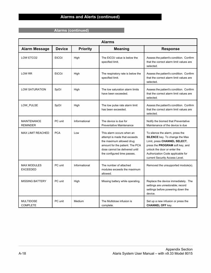
Response
elow the Assess the patient's condition. Confirm that the correct alarm limit values are selected.
below the Assess the patient's condition. Confirm that the correct alarm limit values are selected.
rm limits Assess the patient's condition. Confirm that the correct alarm limit values are selected.
rm limit Assess the patient's condition. Confirm that the correct alarm limit values are selected.
anceNotify the biomed that Preventative Maintenance of the device is due
en an xceeds drug
t. The PCA red until sses.
To silence the alarm, press the SILENCE key. To change the Max Limit, press CHANNEL SELECT, press the PROGRAM soft key, and unlock the door or enter the Authorization Code applicable for current Security Access Level.
ed maximum
Removed the unsupported module(s).
operating. Replace the device immediately. The settings are unrestorable; record settings before powering down the device.
n is Set up a new infusion or press the CHANNEL OFF key.
Alarms and Alerts (continued)
Alarms (continued)
Alarms
Alarm Message Device Priority Meaning
LOW ETCO2 EtCO2 High The EtCO2 value is bspecified limit.
LOW RR EtCO2 High The respiratory rate isspecified limit.
LOW SATURATION SpO2 High The low saturation alahave been exceeded.
LOW_PULSE SpO2 High The low pulse rate alahas been exceeded.
MAINTENANCE REMINDER
PC unit Informational The device is due for Preventative Mainten
MAX LIMIT REACHED PCA Low This alarm occurs whattempt is made that ethe maximum allowedamount for the patiendose cannot be delivethe configured time pa
MAX MODULES EXCEEDED
PC unit Informational The number of attachmodules exceeds theallowed.
MISSING BATTERY PC unit High Missing battery while
MULTIDOSE COMPLETE
PC unit Medium The Multidose infusiocomplete.
Appendix SectionA-18 Alaris System User Manual – with v9.33 Model 8015

Response
empty. hat can be Set. To ion, see and s".
To silence the alarm, press the SILENCE key. The module remains functional and continues the infusion.
nal that a Near has been
None
is lost. The PC unit continues to operate without wireless functionality.
etected for ime.
Assess the patient's condition. Confirm that the correct alarm limit values are selected. Check the Microstream disposable to confirm that the correct disposable is chosen. Confirm the correct disposable placement.
d to the ing to
Attach the sensor to the module.
d to the ring or seconds
Check the patient. Attach the sensor to patient.
t signal Check the sensor. Confirm the correct sensor placement.
stream container. affected
Clear the occlusion on fluid side of the device. If necessary, refill the drip chamber. Press the RESTART key, or press the CHANNEL SELECT key and then the START soft key.
ure sensed usion ule.
Clear the occlusion. Press the RESTART key, or press the CHANNEL SELECT key and then the START soft key.
Alarms and Alerts (continued)
Alarms (continued)
Alarms
Alarm Message Device Priority Meaning
NEAR END OF INFUSION
Syringe, PCA
Low The syringe is almostThis is a timed event tconfigured in the Dataset or change this opt"General Information""Configurable Setting
NEOI Snooze SyringePCA
Reminder A periodic audible sigreminds the user thatEnd of Infusion alarmpreviously silenced.
NETWORK COMMUNICATION ERROR
PC unit Informational Wireless connections
NO BREATH DETECTED
EtCO2 High No breath has been da specified period of t
NO SENSOR SpO2 Informational No sensor is connectemodule while attemptsearch for a patient.
NO SENSOR SpO2 Medium No sensor is connectemodule during monitoafter approximately 30of searching.
NO SIGNAL SpO2 Medium Failure to find a patien
OCCLUDED - FLUID SIDE/EMPTY CONTAINER
Pump High Indicates either an upocclusion or an emptyThe infusion stops onmodule.
OCCLUDED - PATIENT SIDE
Pump High Increased back presswhile infusing. The infstops on affected mod
Appendix SectionAlaris System User Manual – with v9.33 Model 8015 A-19

Response
the patient cted by re.
Clear the occlusion. Press the RESTART key, or press the CHANNEL SELECT key and then the START soft key.
tected. Assess the patient condition. Check the disposable
s pressed ed.
To resume the infusion press RESTART on module or press CHANNEL SELECT and then the START soft key.
paused To resume the infusion press RESTART on module or press CHANNEL SELECT and then the START soft key.
been e infusion med.
Replace the handset when the device is not in use.
paused piratory
Assess the patient status per hospital policy. Press CONFIRM once the patient’s status and monitoring values have been addressed. Press the RESTART key per hospital policy.
To view the trigger of the PCA Pause Alarm, press CHANNEL SELECT > OPTIONS > DRUG EVENT HISTORY, Press the Up/Down key to view the text for the monitoring value causing the PCA module to pause. Press EXIT and then START.
Alarms and Alerts (continued)
Alarms (continued)
Alarms
Alarm Message Device Priority Meaning
PARTIAL OCCLUSION - PATIENT SIDE
Pump High A partial occlusion of side of the IV line detethe Auto-Restart featu
PATIENT NOT DETECTED
EtCO2 Medium The patient is not dec
PAUSED Syringe, PCA, Pump
Informational The pause control waand the infusion stopp
PAUSE-RESTART CHANNEL
Syringe, PCA, Pump
Low The module has beenfor 2 minutes.
PCA HANDSET STUCK
PCA Low The PCA handset haspressed too long. Thcontinues as program
PCA PAUSED - LOCKOUT
PCA High The PCA infusion hasdue to a decline in resstatus
Appendix SectionA-20 Alaris System User Manual – with v9.33 Model 8015

Response
Disc was ing stops on
Disc during an disc
Press the CONFIRM soft key and then the RESTART key.
se has e device is mming
Program the next infusion step or turn the channel off.
inside chamber).
1. Close the roller clamp and open the door.
2. Remove the tubing.
3. Massage the tubing from the top to the bottom to restore the flow.
4. Reload the set and close the door.
5. Press the NEXT soft key.
6. Press the CONFIRM soft key.
7. Open the roller clamp and press the RESTART key.
8. Verify the flow in the drip chamber after restarting the infusion.
9. Change the set if you are unable to establish flow.
ed runtime Press CONFIRM to continue operation with reduced battery capacity or power down and replace the device.
ice is in e door is
Close the roller clamp on administration set or close the door.
is nitoring atient matically
N/A
Alarms and Alerts (continued)
Alarms (continued)
Alarms
Alarm Message Device Priority Meaning
PRESSURE DISC INSERTED
Syringe High The Pressure Sensinginstalled during a runninfusion. The infusionaffected module.
The Pressure Sensingshould not be installedinfusion. Installing thedelivers a bolus.
PROGRAM STEP COMPLETE STATUS
Syringe, PCA, Pump
Informational The Bolus/Loading dobeen delivered and thwaiting for next prograinstructions.
PUMP CHAMBER BLOCKED
Pump High The tubing is blockedPump module (pump
REPLACE BATTERY PC unit Low The battery has reduccapacity.
SAFETY CLAMP OPEN / CLOSE DOOR
Pump High The safety clamp devopen position while thopen.
SEARCHING SpO2, EtCO2
Informational The monitoring deviceattempting to start moand is searching for pvitals. Searching autofollows initialization
Appendix SectionAlaris System User Manual – with v9.33 Model 8015 A-21

Response
nected to itoring or seconds t.
Check the patient. Attach the sensor to the patient.
is hanisms to r the
N/A
g No user respone expected.
libration TE scrolls y. Other sing will
Replace the module with an operational device as soon as possible. Service by qualified personnel is required. Press the CONFIRM soft key to continue.
, with the , senses re is being
the Drive LUSION"
splay.
To silence the alarm and continue with normal operation, press the CONFIRM soft key.
completed ins less ble
Set up a new syringe infusion or press the CHANNEL OFF key.
ION is nit
Replace the device immediately. The settings unrestorable; record the settings before powering down the device.
Alarms and Alerts (continued)
Alarms (continued)
Alarms
Alarm Message Device Priority Meaning
SENSOR OFF SpO2, Medium The sensor is not conthe patient while monafter approximately 30of searching for patien
SENSOR WARMING EtCO2 Informational The monitoring devicepreparing sensor mecsearch for and monitopatient vitals.
SWITCHOVER STATUS
Syringe, PCA, Pump
Informational The device is deliverinmedication/fluid.
SYRINGE CALIBRATION REQUIRED
Syringe, PCA
Medium The module needs cabefore use. CALIBRAin the Message Displamodules currently infucontinue to operate.
SYRINGE DRIVER HEAD ERROR
Syringe, PCA
High A noninfusing moduleplunger grippers openthat excessive pressuapplied downward onHead. The word "OCCscrolls in Message Di
SYRINGE EMPTY Syringe, PCA
High The syringe VTBI hasand the syringe contathan 2% total disposavolume.
SYSTEM ERROR PC unit High A FATAL MALFUNCTdetected on the PC u
Appendix SectionA-22 Alaris System User Manual – with v9.33 Model 8015

Response
timated s prior to
Connect the AC power cord to the power source (alarm silenced). Very low battery will continue to display after the AC is plugged in until the battery has built up sufficent charge to run Alaris System for 5 minutes. To verify that AC is charging, look at the AC LED on the front panel.
eliver the No user respone is expected
Alarms and Alerts (continued)
Alarms (continued)
Alarms
Alarm Message Device Priority Meaning
VERY LOW BATTERY <5 MIN TO SHUTDOWN PLUG IN NOW
PC unit High The battery has an esrun time of five minuteinfusion stopping.
WAIT STATUS PCA Informational Device is waiting to dnext PCA dose.
Appendix SectionAlaris System User Manual – with v9.33 Model 8015 A-23

Plug the PC unit into an AC outlet during storage to ensure a fully charged battery. The AC indicator light ( ) is on when the PC unit is plugged in.
The PC unit is equipped with a 12 volt, 4000 mAh nickel metal hydride battery. The battery is charging whenever the instrument is plugged into an AC receptacle. The life expectancy of the battery is dependent on the amount of use, the depth of discharge, and the state of the charge that is maintained. Generally, the battery has the longest life if the instrument is plugged in and battery use is infrequent. Frequent use of battery power and insufficient battery charge cycles significantly decrease the life of the battery.
Normally a battery will last 2 years if used under proper maintenance. See Proper Battery Maintenance on page A-25.
Use only CareFusion batteries. The use of third party batteries could affect the safety and efficacy of Alaris products.
The PC unit is shipped with the battery in a discharged condition. Before the PC unit is released for use, it should be plugged into a hospital grade AC outlet and the battery charged for at least 16 hours. This ensures proper battery operation when the Alaris System is first set up for patient use.
The battery is intended as a backup system. Leave the power cord connected to an external hospital grade AC power source whenever available.
If the device has been used on battery power, ensure that the battery is fully charged prior to using the device on battery power again. To fully charge a depleted battery connect the device to a hospital grade AC power source for 16 hours.
Storage
Battery Care and Maintenance
Battery Type and Charging
Battery Charging
Appendix SectionA-24 Alaris System User Manual – with v9.33 Model 8015

d)
Do not open, incinerate, or short circuit. Worn-out batteries must be disposed of properly, according to local regulations.
CAUTION
If you plan to store the PC unit at temperatures in excess of 86°F (30°C) for one or more months, remove the battery from the PC unit and store the battery in an environment of 50 - 86°F (10 - 30°C).
If the batteries are to be stored for more than 1 year, they should be fully charged (16 hours) at least once per year to prevent leakage and deterioration in performance due to self-discharge.
When the battery has been out of use for one or more months, it will not have full capacity.
Some temporary reduction in capacity may occur if the battery is repeatedly partially discharged.
Battery replacement should be performed by qualified service personnel while the instrument is not in use.
Do not open, incinerate, or short circuit the battery. Worn-out batteries must be disposed of properly, according to local regulations.
The battery should be conditioned every 12 months by qualified service personnel.
The battery should be replaced every 2 years by qualified service personnel.
Battery Care and Maintenance (Continue
Battery Storage and Use Conditions
Battery Disposal
Proper Battery Maintenance
Appendix SectionAlaris System User Manual – with v9.33 Model 8015 A-25

wirelessIcon
Send the PC unit to Biomed to resolve wireless connectivity issues.
The Wireless Connection soft key is inactive (grayed out) for one of the following reasons:
• The System Maintenance software was used to disable the wireless connection.
• The CF card flashing process was done without the programming of the proper AppConfig file (v9.12 or later).
• A valid network configuration has not been transferred.
To enable the wireless connection, consult the v9 or later System Maintenance software.
At various locations, the PC unit may or may not be able to complete a wireless connection. When connected, the connection icon lights. If the PC unit cannot connect, the connection icon does not light, and device data is stored until a connection can be completed.
The following table explains how the pump functions under various wireless scenarios.
Wireless Connection
Wireless Connection Soft Key
Wireless Connection Scenarios
Full Connectivity No Connectivity Marginal Connectivity
• Connectivity icon lighted
• Near real-time full data transfer
• Connectivity icon not lighted
• Data stored until connection is reestablished
• NA• Data stored and
transferred as PC unit reestablishes connection
W
NOTE:If there is no wireless connection, PC unit data (such as log information) is stored until a connection is re-established. System history and CQI logs are stored in non-volatile compact flash memory and are retained until memory is full and older items are purged.
Appendix SectionA-26 Alaris System User Manual – with v9.33 Model 8015

Failure to perform these inspections can result in improper instrument operation.
WARNING
Preventive maintenance inspections should only be performed by qualified service personnel.
CAUTION
Failure to follow these instructions may result in potential hazards associated with damaged IUI connectors.
WARNING
Inserting a finger or other object into the IUI connector, when the module is attached to the PC unit, could result in electrical shock.
WARNING
To ensure that the Alaris System remains in good operating condition, both regular and preventive maintenance inspections are required. Refer to the System Maintenance software for detailed instructions.
REGULAR INSPECTIONS
Inspect IUI ConnectorsIf any surface contaminants or blue or green deposits are visible, the connector must be replaced.
1. Visually inspect the right side (male) IUI connector for cracks on the entire surface of the black colored plastic housing. See Figures 1 and 2 for the male IUI inspection area and typical cracks.
2. Visually inspect the left side (female) IUI connector for cracks on the edges of the black colored plastic housing.
3. If cracks are found, replace the IUI connector before use.
Inspection Requirements
PROCEDURE FREQUENCY
INSPECT FOR DAMAGE • Exterior Surfaces• IUI Connector*• Keypad• Pole Clamp• Power Cord
• Each usage• Each usage• Each usage• Each usage• Each usage
CLEANING As required
START-UP Each usage
NOTE:* While visually inspecting the IUI connectors, look for fractures on the connectors black-colored plastic. If you see any damage, do not use an instrument with fractured IUI connectors. The IUI connector must be replaced before the instrument can be used again.
Figure 1: Male IUI Connector(right side)
Figure 2: Male IUI Connector
Appendix SectionAlaris System User Manual – with v9.33 Model 8015 A-27

• To prevent an electrical hazard:◦ Turn the instrument off and
unplug the power cord from AC power before cleaning.
◦ Do not spray fluids directly onto the instrument or into the IUI connectors.
◦ Do not steam autoclave, EtO sterilize, immerse the instrument in fluids, or allow fluids to enter the instrument case.
◦ Do not connect a module until the IUI connectors are thoroughly dry.
• Do not use compressed air to dry the instrument; this could force fluid into the instrument.
WARNING
Failure to perform these inspections can result in improper instrument operation.
WARNING
Preventive maintenance inspections should only be performed by qualified service personnel.
CAUTION
Inserting a finger or other object into the IUI connector, when the module is attached to the PC unit, could result in electrical shock.
WARNING
Inspect and clean the product per the following procedures. Read all warnings and cautions before continuing with this procedure.
Refer to the following website for cleaning product information:www.carefusion.com/alarissystemcleaning.
Inspect IUI Connectors
1. Visually inspect the right side (male) IUI connector for cracks on the entire surface of the black colored plastic housing. See Figures 1 and 2 for the male IUI inspection area and typical cracks.
2. Visually inspect the left side (female) IUI connector for cracks on the edges of the black colored plastic housing.
3. If cracks are found, replace the IUI connector before use.
Cleaning
Alaris System
Cleaning Products
Procedure
Figure 1: Male IUI Connector(right Side)
Figure 2: Male IUI Connector
NOTE:While visually inspecting the IUI connectors, look for fractures on the connectors black-colored plastic. If you see any damage, do not use an instrument with fractured IUI connectors. The IUI connector must be replaced before the instrument can be used again.
Appendix SectionA-28 Alaris System User Manual – with v9.33 Model 8015

• The use of chemicals that can damage the surface of the instrument and failure to follow the Alaris product cleaning procedures and the cleaning solution manufacturer's recommended dilutions can result in an instrument malfunction or product damage, such as weakening and cracking of the case, and could void the warranty.
• Do not allow the cleaning solution to contact the IUI connector when cleaning the instrument.
• Do not use hard, abrasive or pointed objects to clean anypart of the instrument.
CAUTION
• Do not allow cleaning solutions to collect on the instrument. Residue buildup might cause the moving parts to become sticky and hinder their operation over time.
• Certain chemicals can damage the surfaces of the instrument. Refer to the following website for a list of chemicals that should NOT be used:
• Do not use chemicals that can damage the surface of the instrument. When possible use cleaning products that are recommended for use by CareFusion.
CAUTION
www.carefusion.com/alarissystemcleaning
Cleaning the Case
1. Make sure the instrument is turned off, unplug the power cord and wipe all of the exposed device surfaces EXCEPT the inter-unit interface (IUI) connectors.
DO NOT use an oversaturated cloth. Be sure to squeeze out excess liquid.
2. Use a dedicated soft-bristled brush to clean the case to remove any visible residue. The brush may also be used to clean narrow or hard-to-reach areas.
DO NOT use any hard, abrasive or pointed objects to clean any part of the instrument.
Cleaning (Continued)
Alaris System (Continued)
Procedure (Continued)
NOTE:Use the recommended healthcare-grade solutions and DO NOT use chemicals that can damage the surfaces of the instrument.
Appendix SectionAlaris System User Manual – with v9.33 Model 8015 A-29

3. Follow the cleaner manufacturer’s instructions on the time to leave it on the device surface. Then, remove the cleaner using a soft cloth dampened with water.
DO NOT allow the cleaner to collect on the instrument.
Cleaning the IUI
4. Apply 70% isopropyl alcohol directly to the dedicated IUI cleaning brush. To prevent cross-contamination, do not dip the brush into the IPA.
DO NOT use the same brush used on the case to clean the IUI connectors. Doing so could inadvertently transfer the cleaner or contaminants to the electrical contacts.
5. Clean both IUIs with the dedicated IUI cleaning brush.
To avoid accidentally depositing fluid on the connectors, DO NOT use any spray cleaners anywhere near the IUI connectors.
NEVER ALLOW ANY CLEANER OTHER THAN 70% IPA TO CONTACT THE IUI CONNECTORS.
Cleaning (Continued)
Alaris System (Continued)
Appendix SectionA-30 Alaris System User Manual – with v9.33 Model 8015

Inserting a finger or other object into the IUI connector, when the module is attached to the PC unit, could result in electrical shock.
WARNING
Drying and Inspection
6. Confirm that the instruments and IUI connectors are thoroughly dry before using them again.
DO NOT attach devices that have not fully dried to one another. “Wet mating” can hinder proper instrument operation.
7. Fully inspect the instrument during each cleaning. Look for any visible external damage such as a cracked or broken door, handle, or latch. Open the door of each pump module and inspect the platen and hinge for cracks or other damage.
DO NOT use a device with any damage. Send it to Biomedical Engineering for repair.
Cleaning (Continued)
Alaris System (Continued)
Appendix SectionAlaris System User Manual – with v9.33 Model 8015 A-31

8. Inspect the IUI connectors on each PC unit and module prior to use. Replace any IUI connector with surface contaminants, blue or green deposits, or cracks.
DO NOT use a device with any cracks or surface contaminants on the IUI connectors. Rather, send it to Biomedical Engineering for repair.
Cleaning (Continued)
Alaris System (Continued)
Appendix SectionA-32 Alaris System User Manual – with v9.33 Model 8015

• Do not use abrasive wipes or tissues on the scanner's window.
• Do not use solvents (such as acetone, benzene, ether, phenol-based agents). These can damage the scanner's finish and window.
• Do not immerse in fluids.
CAUTION
• The instrument case should only be opened by qualified personnel using proper grounding techniques. Prior to performing maintenance, disconnect attached module from the Alaris System and the PC unit from AC power.
• During servicing, an instrument’s configuration settings might be reset to the factory defaults. Qualified hospital/facility personnel are responsible for checking in the instrument and ensuring the current hospital- approved Data Set is loaded.
WARNING
1. Use a clean soft cloth or lens tissue dampened with warm water or a mild nonabrasive detergent-water solution to clean all exposed surfaces.
2. Use a clean soft cloth or lens tissue dampened with water to rinse off cleaning solution.
3. Ensure that window is dry before returning to use.
If the instrument shows evidence of damage in transit, notify the carrier’s agent immediately. Do not return damaged equipment to the factory before the carrier’s agent has authorized repairs.
If the instrument fails to respond as described in this document and the cause cannot be determined, do not use the instrument. Contact qualified CareFusion service personnel.
If it is necessary to return the instrument for service, obtain a return authorization number prior to shipment. Carefully package the instrument (preferably in the original packaging), refer to the return authorization information, and return it to the appropriate service or distribution center. CareFusion does not assume any responsibility for loss of, or damage to, returned instruments while in transit.
.
Technical support, service information, applications, and manuals can be obtained by contacting a CareFusion representative. 888-812-3229.
When submitting any request for service, include:
• model number• a description of difficulty experienced• instrument settings• administration set/lot number• solution(s) used• message displayed at time of difficulty
Service Information
Handheld Scanner
Technical Support
Appendix SectionAlaris System User Manual – with v9.33 Model 8015 A-33

erial and workmanship under date of delivery by CareFusion to
material and workmanship s from the date of delivery by
eriod, the purchaser should riate repair facility. Except as e carried out at CareFusion’s mptly, properly packaged and ent to the repair facility shall be at
ct or consequential damages in uct. This warranty shall apply any subsequent owner or
ly to, and CareFusion shall not ith the purchase or use of any
ervice Representative;
t, the product’s stability or
had the product’s serial or lot
accordance with the written
t are not approved by CareFusion is rovided by CareFusion.
d, and of all other obligations or t, directly or indirectly, the authority areFusion any other liability in
SS OR IMPLIED, INCLUDING R A PARTICULAR PURPOSE OR
Warranty
CareFusion warrants that:
A. Each new Alaris System product is free from defects in matnormal use and service for a period of one (1) year from thethe original purchaser.
B. The battery and each new accessory is free from defects inunder normal use and service for a period of ninety (90) dayCareFusion to the original purchaser.
If any product requires service during the applicable warranty pcommunicate directly with CareFusion to determine the appropprovided otherwise in this warranty, repair or replacement will bexpense. The product requiring service should be returned propostage prepaid by purchaser. Loss or damage in return shipmpurchaser’s risk.
In no event shall CareFusion be liable for any incidental, indireconnection with the purchase or use of any Alaris System prodsolely to the original purchaser. This warranty shall not apply toholder of the product. Furthermore, this warranty shall not appbe responsible for, any loss or damage arising in connection wAlaris System product which has been:
1. repaired by anyone other than an authorized CareFusion S
2. altered in any way so as to affect, in CareFusion’s judgmenreliability;
3. subjected to misuse or negligence or accident, or which hasnumber altered, effaced or removed; or
4. improperly maintained or used in any manner other than in instructions furnished by CareFusion.
5. Customer's use of repair or service parts or disposables thaat Customer's own risk and may void the product warranty p
This warranty is in lieu of all other warranties, express or implieliabilities of CareFusion, and CareFusion does not give or granto any representative or other person to assume on behalf of Cconnection with the sale or use of Alaris System products.
CAREFUSION DISCLAIMS ALL OTHER WARRANTIES, EXPREANY WARRANTY OF MERCHANTABILITY OR OF FITNESS FOAPPLICATION.
See packing inserts for international warranty, if applicable.
WARRANTY
Appendix SectionA-34 Alaris System User Manual – with v9.33 Model 8015

ulations and Standards
Any changes or modifications not expressly approved by the personnel responsible for compliance could void the user's authority to operate the system.
CAUTION
This system complies with part 18 of the FCC Rules (US version only). Operation is subject to the following two conditions:
• This system might not cause harmful interference.• This system must accept any interference received,
including interference that might cause undesired operation.
The digital apparatus does not exceed the Class B limits for radio noise emissions from digital apparatus set out in the radio interference regulations of the Canadian Department of Communications (DOC).
Le present appareil numerique n'emet pas de bruits radiolelectriques depassant les limites applicables aux appareils numeriques de la Classe B prescrites dans le reglement sur le brouillage radioelectrique edicte par le Ministere des Communications du Canada.
This system has been tested and found to comply with the limits for a Class B digital device, pursuant to Part 18 of the FCC Rules. These limits are designed to provide reasonable protection against harmful interference when the system is operated in a commercial environment. This system generates, uses, and can radiate radio frequency energy. If it is not installed and used in accordance with the applicable user manual, it might cause harmful interference to radio communications. Operation of this system in a residential area is likely to cause harmful interference, in which case the user is required to correct the interference at their own expense.
The authority to operate this system is conditioned by the requirement that no modifications are made to the system unless the changes or modifications are expressly approved by CareFusion Corporation.
This Class B digital apparatus meets all requirements of the Canadian Interference-Causing Equipment Regulation.
Reg
Compliance
Electromagnetic Environment
Alaris System
Appendix Section Regulations and StandardsAlaris System User Manual – with v9.33 Model 8015 A-35

s
c Environment—Guidance
for its internal function in normal product offering. . Refer to network card’s user manual for further
not likely to cause interference with nearby
all establishments, including domestic onnected to a public low- voltage power supply for domestic purposes.
Cet appareil numerique de la Classe B respecte toutes les exigences du Reglement sur le materiel brouilleur du Canada.
The Alaris System includes an IEEE 802.11 RF transmitter, as designated by the icon on the rear of the system. It operates on the following frequencies with a maximum radiated power of 100 mW:
• 802.11a: 5 GHz band, up to 54 Mbps physical RF specification.
• 802.11b: 2.4 GHz band, up to 11 Mbps physical RF specification.
• 802.11g: 2.4 GHz band, up to 54 Mbps physical RF specification.
• 802.11n: 5 GHz or 2.4 GHz band, up to 72 Mbps physical RF specification.
The registration numbers are identified on the RF card installed in the rear of the PC unit.
Tables: The Alaris System is intended for use in the electromagnetic environments specified in the following tables.
Compliance (Continued)
Electromagnetic Environment (Continued)
Table 1Electromagnetic Emission
Emissions Test Compliance Electromagneti
CISPR 11RF Emissions Group 1
Alaris System uses RF energy onlyFollowing icon appears on productinformation.
RF emissions are very low and areelectronic equipment.
CISPR 11RF Emissions Class B
Alaris System is suitable for use inestablishments and those directly cnetwork that supplies buildings used
IEC 61000-3-2Harmonic Emissions Class A
IEC 61000-3-3Voltage FluctuationsFlicker Emissions
Complies
Regulations and Standards Appendix SectionA-36 Alaris System User Manual – with v9.33 Model 8015

y
Electromagnetic Environment - Guidance
ors should be wood, concrete, or ceramic.oors are covered with synthetic material, relative
idity should be at least 30%. onnector testing exemption is used, following ESD sitivity symbol appears adjacent to each connector. ris System User Manual – with v9.33 Model 8015" - Not Touch"
ins power quality should be that of a typical mercial or hospital environment.
ins power quality should be that of a typical mercial or hospital environment.
wer frequency magnetic fields should be at levels racteristic of a typical location in a typical commercial ospital environment.
Compliance (Continued)
Electromagnetic Environment (Continued)
Alaris System (Continued)
Table 2Electromagnetic Immunit
Immunity TestIEC
60601-1-2:2007Test Level
Compliance Level
IEC 61000-4-2Electrostatic Discharge (ESD)
For Model 8015, Infusion modules, and Auto-ID module:±8 kV contact±15 kV airFor Model 8015 and monitoring modules:±6 kV contact±8 kV air
±8 kV contact
±15 kV air
For Model 8015, Infusion modules and Auto-ID module:±8 kV contact±15 kV airFor Model 8015 and monitoring modules:±6 kV contact±8 kV air
FlotileIf flhumIf csenAlaDo
IEC 61000-4-4Electrical Fast Transient, Burst (EFT)
±2 kV for power supply lines±1 kV for input/output lines
±2 kV for power supply lines±1 kV for input/output lines
Macom
IEC 61000-4-5Power Line Surge
±1 kV differential mode±2 kV common mode
±1 kV differential mode±2 kV common mode
Macom
IEC 61000-4-8Power Frequency Magnetic Field (50/60 Hz)
3 A/m 400 A/m 50 Hz
400 A/m 60 Hz
Pochaor h
Appendix Section Regulations and StandardsAlaris System User Manual – with v9.33 Model 8015 A-37

y
lectromagnetic Environment - Guidance
power quality should be that of a typical ercial or hospital environment.inued operation of Alaris System is required during mains interruptions, it is recommended that Alaris m be powered from an uninterruptible power supply attery. System does employ an internal short duration y.
propagation is affected by absorption
llular/cordless) telephones and land mobile not be predicted theoretically with accuracy. and electromagnetic site survey should be is System is used exceeds the applicable RF peration. If abnormal performance is relocating the Alaris System.
ss than [V1] V/m.
Compliance (Continued)
Electromagnetic Environment (Continued)
Alaris System (Continued)
Table 2 (Continued)Electromagnetic Immunit
Immunity TestIEC 60601-1-2Test Level
Compliance Level
E
IEC 61000-4-11Voltage Dips, Short Interruptions, and Voltage Variations
<5% UT
(>95% dip in UT) for 0.5 cycle
<5% UT
(>95% dip in UT) for 0.5 cycle
MainscommIf contpowerSysteor a bAlarisbatter
40% UT
(60% dip in UT) for five cycles
40% UT
(60% dip in UT) for five cycles
70% UT
(30% dip in UT) for 25 cycles
70% UT
(30% dip in UT for 25 cycles
<5% UT
(>95% dip in UT) for 5 sec
<5% UT
(>95% dip in UT) for 5 sec
Notes: At 80 MHz and 800 MHz, the higher frequency applies.These guidelines may not apply in all situations. Electromagnetic and reflection from structures, objects, and people.a Field strengths from fixed transmitters, such as base stations for radio (ce
radios, amateur radio, AM and FM radio broadcast and TV broadcast canTo assess the electromagnetic environment due to fixed RF transmitters, considered. If the measured field strength in the location in which the Alarcompliance level above, the Alaris System be observed to verify normal oobserved, additional measures may be necessary, such as reorienting or
b Over the frequency range 150 kHz to 80 MHz, field strengths should be le
Regulations and Standards Appendix SectionA-38 Alaris System User Manual – with v9.33 Model 8015

rt Equipment
lectromagnetic Environment - Guidance
ble and mobile RF communications ment should be used no closer to System (including cables) than mended separation distance calculated quation applicable to frequency of itter.mended Separation Distance:
12 [-----] √P
V2
12 [-----] √P 80 MHz - 800 MHz
E1
12 [-----] √P 80 MHz - 2.5 GHz
E1
recommended separation distance in meters (m).
aximum output power rating of transmitter in watts (W) according to transmitter
manufacturer. strengths from fixed RF transmitters, as mined by an electromagnetic site survey, ld be less than compliance level in each
frequency range.rence might occur in vicinity of
ment marked with following symbol:
Compliance (Continued)
Electromagnetic Environment (Continued)
Alaris System (Continued)
Table 3Electromagnetic Immunity - Life Suppo
Immunity Test IEC 60601-1-2Test Level
Compliance Level
E
IEC 61000-4-6 Conducted RF
IEC 61000-4-3 Radiated RF
10 Vrms150 kHz - 80 MHz
10 V/m80 MHz -2.5 GHz
10 Vrms
10 V/m
PortaequipAlarisrecomfrom etransmRecom __ d =
__ d =
__ d =
d =
P = m
Fielddetershou
Interfeequip
Appendix Section Regulations and StandardsAlaris System User Manual – with v9.33 Model 8015 A-39

tances
ining a minimum distance between s), and the Alaris System as r of the communications equipment.
s table, the recommended separation applicable to the frequency of the ransmitter in watts (W) based on the
ansmitter Frequency (m)
MHz - 800 MHz 800 MHz - 2.5 GHz
12 d = [-----] √P E1
23__ d = [-----] √P E1
0.06 0.12
0.19 0.36
0.6 1.15
1.9 3.64
6 11.5
Compliance (Continued)
Electromagnetic Environment (Continued)
Alaris System (Continued)
Table 4Recommended Separation Dis
Reduce the potential for electromagnetic interference by maintaportable and mobile RF communications equipment (transmitterrecommended in this table, based on the maximum output powe
For transmitters rated at a maximum output power not listed in thidistance (d) in meters (m) can be determined using the equationtransmitter, where P is the maximum output power rating of the ttransmitter manufacturer.
Rated MaximumOutput Power ofTransmitter (W)
Separation Distance Based on Tr
150 kHz - 80 MHzOutside ISM
Bands
150 kHz - 80 MHzIn ISM Bands
80
3.5__ d = [-----] √P V1
12__ d = [-----] √P V2
__
0.01 0.02 0.06
0.1 0.06 0.19
1 0.18 0.6
10 0.55 1.9
100 1.75 6
Regulations and Standards Appendix SectionA-40 Alaris System User Manual – with v9.33 Model 8015

c propagation is affected by absorption
kHz and 80 MHz, and in the frequency that mobile/portable communications atient areas. For this reason, an eparation distance for transmitters in
radio (cellular/cordless) telephones and st] cannot be predicted theoretically with d RF transmitters, an electromagnetic the location in which the Alaris System stem should be observed to verify
l measures might be necessary, such as
ld be less than [V1] V/m.Hz and 80 MHz are 6.765 - 6.795 MHz, Hz.
The CF Wireless Module contains a radio frequency, wireless, local-area network interface (RF card). The RF card allows the Alaris System to communicate with the Alaris Systems Manager connected to the hospital information system. The RF card is compliant with the rules and regulations in the locations where the CF Wireless Module is sold, and is labeled as required.
The United States Federal Communications Commission (FCC) and Industry Canada (IC) identification numbers are visible through the CIB’s clear plastic cover. If an international country approval stamp is required, it is placed adjacent to the identification numbers in the area provided. If the FCC identification number or country approval stamp is not easily visible, the RF card cover may be removed so that the information provided can be read. If the RF card cover is removed, ensure that it is reattached—using the screws that
Compliance (Continued)
Electromagnetic Environment (Continued)
Alaris System (Continued)
Compact Flash Wireless Networking Module
NOTES: Compliance levels raised by IEC 60601-2-24 (Edition 2.0 2012). Performed at the minimum and maximum rated input voltage. UT is the AC mains voltage prior to application of the test level. At 80 MHz and 800 MHz, the higher frequency range applies. These guidelines might not apply in all situations. Electromagneti
and reflection from structures, objects and people. The compliance levels in the ISM frequency bands between 150
range 80 MHz - 2.5 GHz, are intended to decrease the likelihood equipment could cause interference if inadvertently brought into padditional factor of 10/3 is used in calculating the recommended sthese frequency ranges.
Field strengths from fixed transmitters [such as base stations for mobile radios, amateur radio, AM/FM radio broadcast, TV broadcaaccuracy. To assess the electromagnetic environment due to fixesite survey should be considered. If the measured field strength inis used exceeds the applicable RF compliance level, the Alaris Synormal operation. If abnormal performance is observed, additionareorienting or relocating the Alaris System.
Over the frequency range 150 kHz - 80 MHz, field strengths shou The ISM (Industrial, Scientific and Medical) bands between 150 k
13.553 - 13.567 MHz, 26.957 - 27.283 MHz, and 40.66 - 40.70 M
Appendix Section Regulations and StandardsAlaris System User Manual – with v9.33 Model 8015 A-41

were removed, to ensure that the RF card is securely retained and protected against liquid ingress and damage.
The Class B digital device limits are designed to provide reasonable protection against harmful interference when the device is operated as intended. This device generates, uses, and can radiate radio frequency energy. If it is not installed and used in accordance with the applicable user manual, it might cause harmful interference to radio communications. Operation of this device in a residential area is likely to cause harmful interference, in which case the user is required to correct the interference at their own expense. There is, however, no guarantee that interference will not occur in a particular installation.
If the device does cause harmful interference to radio or television reception (determined by powering system off and on), one or more of the following corrective actions should be taken:
• Reorient or relocate receiving antenna.
• Increase separation distance between system and receiver.
• Connect system into an outlet on a circuit different from that to which receiver is connected.
This Class B digital device meets the requirements of the Canadian Interference Causing Equipment Regulations.
Cet appareil numérique de la Classe B respecte toutes les exigences du Reglement sur le Matériel Brouilleur du Canada.
This Class B digital device meets the requirements of the International community.
Australian Communications Authority Applicant:
CareFusion Australia 316 Pty LTDP.O. Box 355Seven Hills West, NSWAustralia 2147
Phone: 02 9838 0255Fax: 02 9674 4444
Compliance (Continued)
Electromagnetic Environment (Continued)
Compact Flash Wireless NetworkingModule (Continued)
Regulations and Standards Appendix SectionA-42 Alaris System User Manual – with v9.33 Model 8015

The Alaris System has been assessed and complies with the following standards:
PC unit and overall System: CAN/CSA C22.2 No. 60601-1-1 (3.0 Edition 2014), IEC 60601–1 (3.1 Edition 2012), 60601-1-2 (2007), 60601-1-8 (2012)
Auto-ID module: IEC 60825–1 (Edition 3.0 2014) (LEDs used in Auto-ID module are not regulated by FDA in the United States; however, they are classified as a CLASS 1 LED PRODUCT in other countries under this standard.)
Compact Flash Wireless Networking Module: Class B digital device limits pursuant to Parts 15 (RF Devices and Computing Devices 2015) and 18 (Medical Devices) of the FCC Rules and Regulations 2015. To comply with FCC and Industry Canada exposure requirements, the CF Wireless Module is approved for operation when there is more than 20 cm between the antenna and the user’s or patient’s body.
EtCO2 module: ISO 80601-2-55 (2011), IEC 60601-2-49 (2011)
PCA, Pump and Syringe modules: IEC 60601-2-24 (Edition 2.0 2012), ANSI/ AAMI ID26 (2013)
Compliance (Continued)
Standards
Appendix Section Regulations and StandardsAlaris System User Manual – with v9.33 Model 8015 A-43

The Alaris System when upgraded to v9.33 software only has been assessed and complies with the following standards:
PC unit and overall System: UL 60601–1 (2003), CAN/CSA C22.2 No. 601.1-M90 (2.0 Edition 1990), IEC 60601–1 (2.0 Edition 1988)
Auto-ID module: IEC 60825–1 (2007) (LEDs used in Auto-ID module are not regulated by FDA in the United States; however, they are classified as a CLASS 1 LED PRODUCT in other countries under this standard.)
Compact Flash Wireless Networking Module: Class B digital device limits pursuant to Parts 15 (RF Devices and Computing Devices 2015) and 18 (Medical Devices) of the FCC Rules and Regulations 2015. To comply with FCC and Industry Canada exposure requirements, the CF Wireless Module is approved for operation when there is more than 20 cm between the antenna and the user’s or patient’s body.
EtCO2 module: ISO 9918:1993, ASTM F 1456 (2001), ASTM F 1463 (1993), EN 475 (1995), EN 864 (1997)
PCA, Pump and Syringe modules: IEC 60601-2-24 (1.0 Edition (1998), ANSI/ AAMI ID26 (1998)
SpO2 module: EN 865 (1997)
Compliance (Continued)
Standards (Continued)
Regulations and Standards Appendix SectionA-44 Alaris System User Manual – with v9.33 Model 8015

Device Manufactured with v9.33 Software
Applies
Applies
Applies
Applies
Applies
Additional test evidence is available for the EtCO2 hardware included in devices manufactured with v9.33 software. This test evidence will not apply to devices upgraded to v9.33.
Compliance (Continued)
Hardware Dependencies
EtCO2 Hardware Dependencies
v9.33 Software Upgrade Only
Note 1 for Accuracy of EtCO2 Readings (on page 5-20)
Does not apply
Accuracy Specification for Interfering Gases (on page 5-20)
Does not apply
Waveform Sampling (on page 5-22) Does not apply
Respiration Rate Test Table (on page 5-26)
Does not apply
Note 2 for Accuracy in Respiration Rate Test Table (on page 5-26)
Does not apply
Appendix Section Regulations and StandardsAlaris System User Manual – with v9.33 Model 8015 A-45

CareFusion, Alaris, Guardrails, SmartSite, and the CareFusion logo are trademarks or registered trademarks of CareFusion Corporation or one of its affiliates. All other trademarks are the property of their respective owners.
Trademarks
Regulations and Standards Appendix SectionA-46 Alaris System User Manual – with v9.33 Model 8015


Alaris System User Manual – with v9.33 Model 8015