Akva Lux II TD/S -
28
Danfoss District Energy MAKING MODERN LIVING POSSIBLE Akva Vita II TD & S Akva Lux II / Akva Les II TD & S Instructions for installation and use
Transcript of Akva Lux II TD/S -

Danfoss District Energy
MAKING MODERN LIVING POSSIBLE
Akva Vita II TD & SAkva Lux II / Akva Les II TD & S
Instructions for installation and use
2
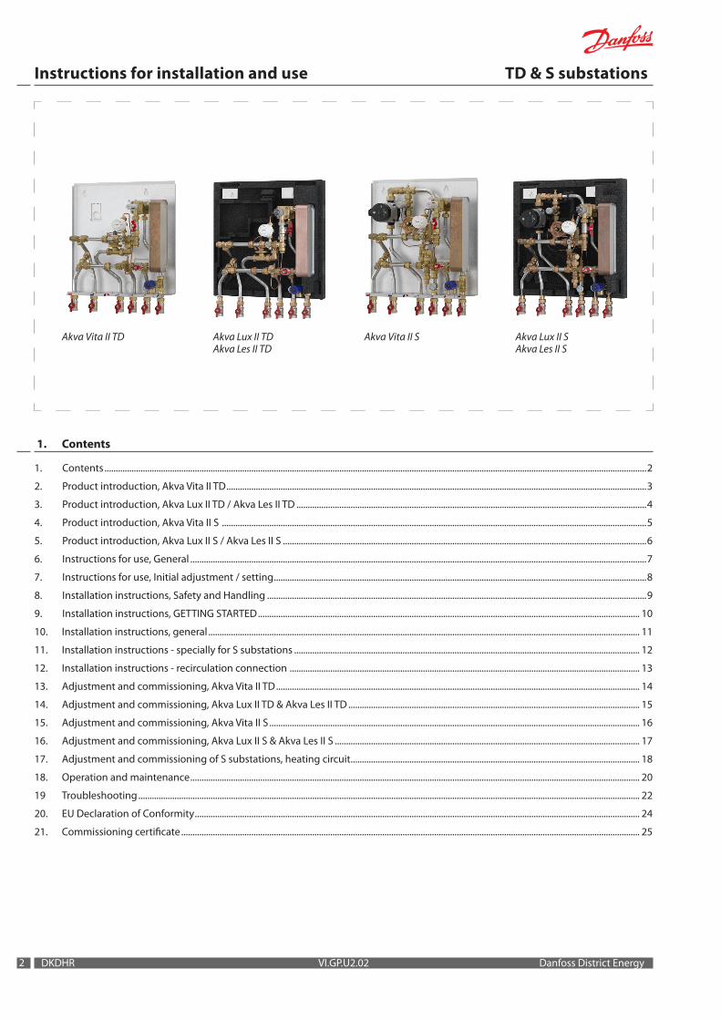
1. Contents
Instructions for installation and use TD & S substations
DKDHR VI.GP.U2.02 Danfoss District Energy
1. Contents ................................................................................................................................................................................................................................................2
2. Product introduction, Akva Vita II TD ..........................................................................................................................................................................................3
3. Product introduction, Akva Lux II TD / Akva Les II TD ...........................................................................................................................................................4
4. Product introduction, Akva Vita II S ............................................................................................................................................................................................5
5. Product introduction, Akva Lux II S / Akva Les II S .................................................................................................................................................................6
6. Instructions for use, General ..........................................................................................................................................................................................................7
7. Instructions for use, Initial adjustment / setting .....................................................................................................................................................................8
8. Installation instructions, Safety and Handling ........................................................................................................................................................................9
9. Installation instructions, GETTING STARTED ......................................................................................................................................................................... 10
10. Installation instructions, general ............................................................................................................................................................................................... 11
11. Installation instructions - specially for S substations ......................................................................................................................................................... 12
12. Installation instructions - recirculation connection ........................................................................................................................................................... 13
13. Adjustment and commissioning, Akva Vita II TD ................................................................................................................................................................. 14
14. Adjustment and commissioning, Akva Lux II TD & Akva Les II TD ................................................................................................................................. 15
15. Adjustment and commissioning, Akva Vita II S .................................................................................................................................................................... 16
16. Adjustment and commissioning, Akva Lux II S & Akva Les II S ....................................................................................................................................... 17
17. Adjustment and commissioning of S substations, heating circuit ................................................................................................................................ 18
18. Operation and maintenance ....................................................................................................................................................................................................... 20
19 Troubleshooting .............................................................................................................................................................................................................................. 22
20. EU Declaration of Conformity ..................................................................................................................................................................................................... 24
21. Commissioning certificate ........................................................................................................................................................................................................... 25
Akva Vita II TD Akva Lux II TDAkva Les II TD
Akva Vita II S Akva Lux II SAkva Les II S

1 2 3 4 5 6
Top view
Wall
550
32580
520
2544
310
45 65 65 65130100
Plate heat exchanger, domestic hot water, type Danfoss XB06H-1Di�erential pressure controller, Danfoss AVPL 0.1–0.25 barDirt strainer, REDAN, embedded in T-pieceNon-return valveBall valveSafety valve, domestic hot water, 10 barThermometerPressure outlet 1/2"
HE SUPPLY
HE RETURN
Sensor pocketFitting piece for meter 3/4" x 110 x 165 mmDHW controller, PM2+PDanfoss FJVR for by-pass/circulation
DHW
DCW
DH. RETURN
DH.SUPPLY
(By-pass) (factory connection)
33
Instructions for installation and use TD & S substations
Danfoss District Energy VI.GP.U2.02 DKDHR
2. Product introduction, Akva Vita II TD
Principal components1.2.3.4.5.6.7.8.9.
13.
F.C.
Plate heat exchanger, brazed, domestic hot waterDomestic hot water controller PM2+PBypass thermostat, Danfoss FJVRDifferential pressure controller, AVPLSafety valveFitting piece for meterThermometer, DHWDirt strainerSensor pocketWhite-painted cover
Filter on cold water supplyThe unit has been prepared for recirculation. Fitting set for recirculation connection available as extra equipment
Standard item numberAkva Vita II TD H04.393.001Akva Vita II TD with cover H04.393.001K
Accessories available as extra equipment (mounting on site)Recirculation pipe set - VVS no. 374976.810For systems that feature DHW recirculation.
Danfoss Expansion Unit - VVS no. 374972.820.The expansion unit is available as extra equipment for systems where a floor drain is to be avoided. (Must not be used in systems with domestic hot water recirculation).
Booster set/pressure intensifier - VVS no. 374994.820.The booster set can be connected as extra equipment in areas with low district heating differential pressure.
1” Fitting set for meter (max. 130 mm) - VVS no. 374929.918For meters with 1” connectors.
1
6
6
5
4
3
2
8
8
7
9
9
F
13C

535
618
55
325
284
481
72,5
285
37,5 100 130 65 65 65
4454138
206333
535
535
618
32572,5
55285
37,5 100 130 65 65 65
44
13C
2 Plate heat exchanger, domestic hot water, type Danfoss XB06H-14 Differential pressure controller, Danfoss AVPL 0.1–0.25 bar5 Dirt strainer, REDAN, embedded in T-piece6 Non-return valve7 Ball valve12 Safety valve, domestic hot water 10 bar13 Thermometer14 Pressure outlet 1/2"23 Sensor pocket24 Fitting piece for meter, 3/4" x 110/165 mm38 Domestic hot water controller, Danfoss PTC2 + P 3,040 Danfoss FJVR for by-pass/circulation------------------------------61 Circulation pipe (not part of the delivery)62 Non-return valve (not part of the delivery)64 Pump, DHW recirc. (not part of the delivery)
HE RETURN
HESUPPLY
(factory connection)
DHW
DCW
DH. RETURN
DH. SUPPLY
DHW RECIRC
4
Instructions for installation and use TD & S substations
DKDHR VI.GP.U2.02 Danfoss District Energy
3. Product introduction, Akva Lux II TD / Akva Les II TD
Principal components1.2.3.4.5.6.7.8.9.
13.
F.C.
Plate heat exchanger, brazed, domestic hot waterDomestic hot water controller, PTC2+PBypass thermostat, Danfoss FJVRDifferential pressure controller, AVPLSafety valveFitting piece for meterThermometer, hot waterDirt strainerSensor pocketWhite-painted cover
Filter on cold water supplyThe unit has been prepared for recirculation. Fitting set for recirculation connection is available as extra equipment.
Standard item numberAkva Lux II TD 26 H05.393.001Akva Lux II TD 26 with cover H05.393.001KAkva Lux II TD 40 H05.393.002Akva Lux II TD 40 with cover H05.393.002K
Akva Les II TD 60+ H05.393.006Akva Les II TD 60+ with cover H05.393.006K
Accessories available as extra equipment (mounting on site)Recirculation pipe set - VVS no. 374976.810For systems that feature domestic hot water recirculation.
Danfoss Expansion Unit - VVS no. 374972.820.The expansion unit is available as extra equipment for systems where a floor drain is to be avoided. (Must not be used in systems with domestic hot water recirculation).
Booster set/pressure intensifier - VVS no. 374994.820.The booster set can be connected as extra equipment in areas with low district heating differential pressure.
1” Fitting set for meter (max. 130 mm) - VVS no. 374929.918For meters with 1” connectors.
1
6
6
5
4
3
2
8
8
7
9
9
F

1 2 3 4 5 6
Top view
550
32580
520
2544
310
45 65 65 65130100
5413
8
218.5
340.5
451
254
8
7
1
6
6
5
43
2
8
8
7
9
F
13
9
12
1110
K
55
Instructions for installation and use TD & S substations
Danfoss District Energy VI.GP.U2.02 DKDHR
4. Product introduction, Akva Vita II S
RADIATOR HE SUPPLY
FLOOR HE SUPPLY
FLOOR HE RETURN
RADIATOR HE RETURN
(factory connection)
DHW
DCW
DH. RETURN
DH. SUPPLY
2 Plate heat exchanger, domestic hot water, type Danfoss XB06H-14 Differential pressure controller, Danfoss AVPL 0.1-0.25 bar5 Dirt strainer, REDAN, embedded in T-piece6 Non-return valve7 Ball valve8 Pump, Wilo Smart 15/6 -130 230V or Grundfos Alpha2 L12 Safety valve, domestic hot water 10 bar13 Thermometer14 Pressure outlet 1/2"17 Air vent23 Sensor pocket24 Fitting piece for meter, 3/4" x 110/165 mm30 Redan Thermostat, kvs 1.238 Domestic hot water controller, PM2+P40 Danfoss FJVR for by-pass/circulation43 Blind plate
Principal components1.2.3.4.5.6.7.8.9.
10.11.12.13.
F.K.C.
Plate heat exchanger, brazed, domestic hot waterDomestic hot water controller PM2+PBypass thermostat, Danfoss FJVRDifferential pressure controller, AVPLSafety valveFitting piece for meterThermometer, ‹ floor heating, › thermometer, domestic hot waterDirt strainerSensor pocketPump, Wilo Yonos PARAThermostatAir valveWhite-painted cover
Filter on cold water supplyNon-return valve - insertThe substation has been prepared for recirculation. Fitting set for recirculation connection is available as extra
Standard item numberAkva Vita II S A14.393.001Akva Vita II S with cover A14.393.001K
Accessories available as extra equipment (mounting on site)Recirculation pipe set - VVS no. 374976.810For systems that feature domestic hot water recirculation.
Danfoss Expansion Unit - VVS no. 374972.820.The expansion unit is available as extra equipment for systems where a floor drain is to be avoided. (Must not be used in systems with domestic hot water recirculation).
Booster set/pressure intensifier - VVS no. 374976.850.The booster set can be connected as extra equipment in areas with low district heating differential pressure.
1” Fitting set for meter (max. 130 mm) - VVS no. 374929.918For meters with 1” connectors.
C

13
DHW
DHW CIRC
DCW
DH. RETURN
DHSUPPLY
RADIATOR HE SUPPLY
RADIATOR HE RETURN
FLOOR HE SUPPLY
FLOOR HE RETURN
Plate heat exchanger, domestic hot water, type Danfoss XB06H-1Di�erential pressure controller, Danfoss AVPL 0.1-0.25 barDirt strainer, REDAN, embedded in T-pieceNon-return valveBall valvePump, Grundfos Alpha2 L 15–60 130 230VSafety valve, domestic hot water 10 barThermometerPressure outlet 1/2"Air ventSensor pocketFitting piece for meter, 3/4" x 110/165 mmRedan Thermostat, kvs 1.2Domestic hot water controller, Danfoss PTC2 + P 3,0Danfoss FJVR for by-pass/circulationBlind plate
Circulation pipe (not part of the delivery)Non-return valve (not part of the delivery)Pump, DHW recirc. (not part of the delivery)
(By-pass) (factory connection)
C
535
618
55
325
284
481
72,5
285
37,5 100 130 65 65 65
4454138
206333
535
535
618
32572,5
55285
37,5 100 130 65 65 65
44
1
6
6
5
4 3
2
8
8
7
9
F
9
12
1110
K
6
Instructions for installation and use TD & S substations
DKDHR VI.GP.U2.02 Danfoss District Energy
5. Product introduction, Akva Lux II S / Akva Les II S
Principal components1.2.3.4.5.6.7.8.9.
10.11.12.13.
F.K. C.
Plate heat exchanger, soldered, domestic hot waterDomestic hot water controller, PTC2+PBypass thermostat, Danfoss FJVRDifferential pressure controller, AVPLSafety valveFitting piece for meterThermometer, ‹ floor heating, › thermometer, domestic hot waterDirt strainerSensor pocketPump – Grundfos Alpha2 ThermostatAir valveWhite-painted cover
Filter on domestic cold water supplyNon- return valve, insertThe substation has been prepared for recirculation. Fitting set for recirculation connection is available as extra equipment.
Standard item numberAkva Lux II S 26 A15.393.001Akva Lux II S 26 with cover A15.393.001KAkva Lux II S 40 A15.393.002Akva Lux II S 40 with cover A15.393.002K
Akva Les II S 60+ H05.393.006Akva Les II S 60+ with cover H05.393.006K
Accessories available as extra equipment (mounting on site)Recirculation pipe set - VVS no. 374976.810For systems that feature domestic hot water recirculation.
Danfoss Expansion unit - VVS no. 374972.820.The expansion unit is available as extra equipment for systems where a floor drain is to be avoided. (Must not be used in systems with domestic hot water recirculation).
Booster set/pressure intensifier - VVS no. 374976.850.The booster set can be connected as extra equipment in areas with low district heating differential pressure.
1” Fitting set for meter (max. 130 mm) - VVS no. 374929.918For meters with 1” connectors.

77
Instructions for installation and use TD & S substations
Danfoss District Energy VI.GP.U2.02 DKDHR
6. Enduser instructions, General
InstructionsPlease read these instructions carefully before installing and commis-sioning this substation. The manufacturer accepts no liability for loss or damage resulting from failure to comply with these instructions for use. Read and follow these instructions carefully to prevent the risk of physical injury and/or damage to property. Exceeding the recommended operating parameters appreciably increases the risk of personal injury and/or damage to property.
Installation, commissioning and maintenance must be carried out by qualified and authorised personnel (both plumbing and electri-cal work).Once the station has been installed and is operating, there is nor-mally no need to alter the settings or other functions. The district heating substation is very reliable and easy to operate.
If necessary, you can change the temperature settings as described on page 8. For more detailed information about the substation, see the sections concerning installation and commissioning.
DescriptionThese instructions apply to two substation types (TD and S) – which are both fitted with an instantaneous water heater and designed for direct connection to the district heating supply.
TD substations are fitted with a differential pressure controller that maintains a constant pressure in the radiators. The supply tempera-ture to the radiators is always identical to the district heating supply temperature. The room temperature is adjusted solely using the radiator thermostats.
S substations are fitted with a differential pressure controller that maintains a constant pressure in the heating circuit(s). The supply temperature to the floor heating is regulated using the thermostat in the substation. S substations are also fitted with a pump. In rooms with floor heating, the temperature is regulated using the floor heating thermostat for the room in question. In rooms with ra-diators, the temperature is regulated using the radiator thermostats.Alternatively, the heating circuits can be regulated using fully auto-matic Danfoss ECL weather compensation equipment (not standard).
We recommend regular inspections of the substation - ideally in connection with readings of the district heating meter. Pay special attention to any leaks and an excessively high return temperature in the district heating circuit (poor cooling of the district heating water). Cooling – i.e. the difference between the supply and return temperature of the district heating water – has a significant effect on the overall energy economy. Therefore, it is important to focus on the supply and return temperature in the heating system. The difference should typically be 30–35°C in systems that operate with radiators. In systems that feature floor heating, the difference is typically 5–10°C. In these systems, it is important that the supply temperature does not exceed 35°C.Please note that a low district heating return temperature is directly dependent on the return temperature from the heating/floor heating circuit and the return temperature of the domestic hot water recircula-tion (in systems with domestic hot water recirculation). It is therefore important to focus on these return temperatures.
Warning! Hot surfacesParts of the substation may be very hot and can cause burn in-juries. Be very careful when you are in the immediate vicinity of the unit.
Warnings about high pressure and high temperatureThe maximum supply temperature in the district heating net-work can be up to 120°C and the operating pressure can be up to 16 bar. This may result in a risk of scalding from touching the substation and from outflow of the medium (water/steam). Ex-ceeding the substation design data and operating parameters for pressure and temperature carries an appreciable risk of personal injury and/or damage to property.
EmergenciesIn the event of fire, leaks or other hazards, immediately shut off all sources of energy to the substation, if possible, and call for appropriate assistance.If the domestic hot water is discoloured or malodorous, shut off all ball valves on the substation notify all users and call for profes-sional assistance without delay.
Cooling from the water heater alone:During tapping, the level of cooling will typically be 30–35°C. When domestic hot water is not being tapped, it is completely normal for the return temperature from the water heater to rise slightly. In this situa-tion, the district heating meter will register very modest consumption as the volume of water is very small. On substations with recirculation, the calorie meter registers the heat loss in the recirculation pipe.
IrregularitiesWhen reading the meter, check all joints and connections for leaks. If you identify any irregularities/leaks, contact your professional provider for assistance. Check the troubleshooting section before contacting your professional provider.
pin
8
Instructions for installation and use TD & S substations
DKDHR VI.GP.U2.02 Danfoss District Energy
7. Enduser instructions, Initial adjustment/setting
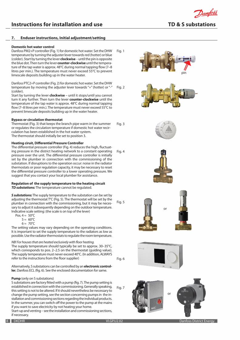
Domestic hot water controlDanfoss PM2+P controller (Fig. 1) for domestic hot water. Set the DHW temperature by turning the adjuster lever towards red (hotter) or blue (colder). Start by turning the lever clockwise – until the pin is opposite the blue dot. Then turn the lever counter-clockwise until the tempera-ture of the tap water is approx. 48°C during normal tapping flow (7–8 litres per min.). The temperature must never exceed 55°C to prevent limescale deposits building up in the water heater.
Danfoss PTC2+P controller (Fig. 2) for domestic hot water. Set the DHW temperature by moving the adjuster lever towards “+” (hotter) or “-” (colder). Start by turning the lever clockwise – until it stops/until you cannot turn it any further. Then turn the lever counter-clockwise until the temperature of the tap water is approx. 48°C during normal tapping flow (7–8 litres per min.). The temperature must never exceed 55°C to prevent limescale deposits building up in the water heater.
Bypass or circulation thermostatThermostat (Fig. 3) that keeps the branch pipe warm in the summer or regulates the circulation temperature if domestic hot water recir-culation has been established in the hot water system.The thermostat should initially be set to position 3.
Heating ciruit, Differential Pressure ControllerThe differential pressure controller (Fig. 4) reduces the high, fluctuat-ing pressure in the district heating network to a constant operating pressure over the unit. The differential pressure controller is initially set by the plumber in connection with the commissioning of the substation. If disruptions to the operation occur: noise in the radiator thermostats or poor regulation capacity, it may be necessary to reset the differential pressure controller to a lower operating pressure. We suggest that you contact your local plumber for assistance.
Regulation of the supply temperature to the heating circuitTD substations: The temperature cannot be regulated.
S substations: The supply temperature to the substation can be set by adjusting the thermostat T°C (Fig. 5). The thermostat will be set by the plumber in connection with the commissioning, but it may be neces-sary to adjust it subsequently depending on the outdoor temperature.Indicative scale setting: (the scale is on top of the lever) Pos. 4 ≈ 50°C 5 ≈ 60°C 6 ≈ 70°CThe setting values may vary depending on the operating conditions. It is important to set the supply temperature to the radiators as low as possible. Use the radiator thermostats to regulate the room temperature.
NB! For houses that are heated exclusively with floor heating. The supply temperature should typically be set to approx. 30–35°C, which corresponds to pos. 2–2.5 on the thermostat (guiding value). The supply temperature must never exceed 40°C. (In addition, ALWAYS refer to the instructions from the floor supplier)
Alternatively, S substations can be controlled by an electronic control-ler, Danfoss ECL (fig. 6). See the enclosed documentation for same.
Pump (only on S substations)S substations are factory fitted with a pump (fig. 7). The pump setting is established in connection with the commissioning. Generally speaking, this setting is not to be altered. If it should nevertheless be necessary to change the pump setting, see the section concerning pumps in the in-stallation and commissioning sections regarding the individual products. In the summer, you can switch off the power to the pump at the mains if you want to save electricity by not heating your home.Start-up and venting – see the installation and commissioning sections, if necessary.
Fig. 1
Fig. 2
Fig. 3
Fig. 4
Fig. 5
Fig. 7
or
or
Fig. 6
99
Instructions for installation and use TD & S substations
Danfoss District Energy VI.GP.U2.02 DKDHR
8. Installation instructions, Safety and Handling
InstructionsPlease read these instructions carefully before installing and com-missioning this unit. The manufacturer accepts no liability for loss or damage resulting from failure to comply with these instructions for use. Read and follow these instructions carefully to prevent the risk of physical injury and/or damage to property. Exceeding the recommended operating parameters appreciably increases the risk of personal injury and/or damage to property.Installation, commissioning and maintenance must be carried out by qualified and authorised personnel (both plumbing and electri-cal work).
Heat sourceThe substation is primarily designed for connection to district heating. Alternative energy sources can be used if the operating conditions are equivalent to district heating at all times.
ApplicationThe substation is designed exclusively to heat water.The substation must not be used to heat other media.The substation is to be connected to the household piping in a frost-free room, where the temperature does not exceed 50°C, and where the relative humidity is not higher than 80%. The substation must not be covered, bricked in or otherwise cut off from access.
Choise of materialsOnly use materials that comply with local regulations.
CorrosionThe maximum chlorine content of the medium must not be higher than 300 mg/l. The risk of corrosion increases considerably if the recommended chlorine content is exceeded.
Safety valve(s)Safety valves must always be installed in accordance with the appli-cable local regulations.
Noise level≤ 55 dB
ConnectionIt must be possible to cut off all energy sources to the unit – including electrical connections – at all times.
Warning! Hot surfacesParts of the unit may be very hot and can cause burn injuries. Be very careful when you are in the immediate vicinity of the unit.
Warnings about high pressure and high temperatureThe maximum supply temperature in the district heating network can be up to 120°C and the operating pressure can be up to 16 bar. This may result in a risk of scalding from touching the substation and from outflow of the medium. Exceeding the substation design data and operating parameters for pressure and temperature carries an appreciable risk of personal injury and/or damage to property.
EmergenciesIn the event of fire, leaks or other hazards, immediately shut off all energy sources to the substation, if possible, and call appropriate assistance.If the domestic hot water is discoloured or malodorous, shut off all ball valves on the substation, notify all users and call profes-sional assistance without delay.
Warning about damage during transportOn reception of the substation, and before installing it, check for any evidence of damage during transport. The substation must be handled and moved with the greatest care and attention.
NB! - Tightening of connectionsBefore filling the substation with water, ALL pipe connections MUST be retightened, as vibrations during transport may have caused leaks. Once the substation has been filled and the system is hot, ALL pipe connections MUST be retightened once more.DO NOT OVERTIGHTEN THE PIPE CONNECTIONS – see page 11, “Test & connections”.
StorageBefore installation, the unit(s) must be stored in a dry, heated (i.e. frost-free) room.(Relative humidity max. 80% and storage temp. 5–70°C).
The units must not be stacked higher than the limit at the factory (max. 8 layers). Units supplied in cardboard packaging must be lifted using the handles incorporated in the packaging. Units must be placed on pallets for transport/moving across large distances.As far as possible, do not lift the unit by the pipes. Lifting by the pipes may cause leaks. REMEMBER to retighten.
DisposalDispose of the packaging in accordance with the local regulations for disposal of used packaging materials.
The substation is made of materials that cannot be disposed of together with household waste. Close all energy sources and disconnect all connection pipes. Disconnect and dismantle the product for disposal in accordance with the appli-cable local regulations for the disposal of the individual components.
HandlingWe recommend that you wear suitable safety footwear while handling and installing the substation.
Primary
supply returnDistrict heating
Domestic hot water
DHW DCW
Secondary
HEreturn supply
10
Instructions for installation and use TD & S substations
DKDHR VI.GP.U2.02 Danfoss District Energy
9. Installation instructions, GETTING STARTED
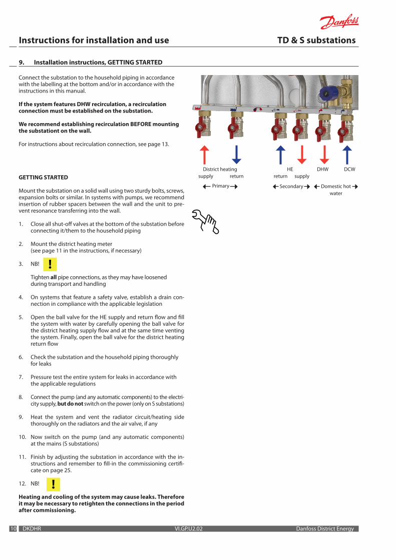
Connect the substation to the household piping in accordance with the labelling at the bottom and/or in accordance with the instructions in this manual.
If the system features DHW recirculation, a recirculation connection must be established on the substation.
We recommend establishing recirculation BEFORE mounting the substationt on the wall.
For instructions about recirculation connection, see page 13.
GETTING STARTED
Mount the substation on a solid wall using two sturdy bolts, screws, expansion bolts or similar. In systems with pumps, we recommend insertion of rubber spacers between the wall and the unit to pre-vent resonance transferring into the wall.
1. Close all shut-off valves at the bottom of the substation before connecting it/them to the household piping
2. Mount the district heating meter (see page 11 in the instructions, if necessary)
3. NB!
Tighten all pipe connections, as they may have loosened during transport and handling
4. On systems that feature a safety valve, establish a drain con- nection in compliance with the applicable legislation
5. Open the ball valve for the HE supply and return flow and fill the system with water by carefully opening the ball valve for the district heating supply flow and at the same time venting the system. Finally, open the ball valve for the district heating return flow
6. Check the substation and the household piping thoroughly for leaks
7. Pressure test the entire system for leaks in accordance with the applicable regulations
8. Connect the pump (and any automatic components) to the electri-city supply, but do not switch on the power (only on S substations)
9. Heat the system and vent the radiator circuit/heating side thoroughly on the radiators and the air valve, if any
10. Now switch on the pump (and any automatic components) at the mains (S substations)
11. Finish by adjusting the substation in accordance with the in-structions and remember to fill-in the commissioning certifi-cate on page 25.
12. NB!
Heating and cooling of the system may cause leaks. Therefore it may be necessary to retighten the connections in the period after commissioning.
!
!

1111
Instructions for installation and use TD & S substations
Danfoss District Energy VI.GP.U2.02 DKDHR
10. Installation instructions, general
The installation, connection and maintenance of the substation must be performed by qualified and authorised personnel. Installation must always be performed in accordance with the applicable legisla-tion and in compliance with these instructions. The substation must be installed so that it is freely accessible and can be maintained without unnecessary disruption. Lift the substa-tion by its mounting plate/rear section and secure it to a solid wall using 2 sturdy bolts, screws or expansion bolts positioned in the two keyholes in the mounting plate/rear section. On Akva Vita II S substations, we recommend positioning of rub-ber spacers between the wall and the unit to prevent the transfer of resonance noise from the pump into the wall.Before commissioning, rinse all the pipes in the household piping sys-tem thoroughly to remove any impurities, and check and clean the dirt strainers in the substation.
For fully insulated systemsThe insulation front panel on the Akva Lux II / Les II TD and the Akva Lux II / Les II S substations can be removed without using tools. Take hold of the air duct in the top and bottom of the front insulation section (see the photos to the right) and pull carefully forward until the front insulation section releases from the rear section. Then pull gently until the front section is free from the components.
Test and connectionsBefore filling the system with water, retighten all the pipe connec-tions because vibrations and shocks during transport and handling may have caused leaks. Once the system has been filled with water, tighten all the pipe connections once more before performing pres-sure test for leaks. After heating of the system, check all the connec-tions and retighten if necessary.Please note that the connections may feature EPDM rubber gaskets! Therefore, it is important that you DO NOT OVERTIGHTEN the union nuts. Overtightening may result in leaks. Leaks caused by overtightening or failure to retighten connections are not covered by the warranty.
Heat meter, fitting piecesThe unit is equipped with fitting pieces for heat heating meter on the district heating supply and return lines – dimensions 3/4” x 110 mm – 3/4 x 165 mm.
Fitting of heat meters - Close the ball valves on the district heating and the heating sides- Loosen the union nuts at both ends of the fitting piece and
remove it- Fit the meter – remember to insert gaskets - Fit the temperature sensors in the sensor pockets (see the meter
instructions)- Tighten the pipe connections before commissioning the meter.
Meter display (reading unit)The meter’s reading unit can be positioned as shown in the photo to the right, such that the meter reading can be made simply be removing the top left-hand corner of the insulation cover.
Safety valveAlways lead the blow-off pipe from the safety valve to a drain in accordance with applicable legislation.
Safety valve – cut-out in the insulation coverOn fully insulated models, it is necessary to cut a hole in the cover (for the blow-out pipe from the safety valve) – see the photo to the right.
!

12
Instructions for installation and use TD & S substations
DKDHR VI.GP.U2.02 Danfoss District Energy
11. Installation instructions – specially for S substations
Controller ECL 210Supply voltage: 230 V AC – 50 HzPower consumption: 5 VA
Actuator AMV 150 Supply voltage: 230 V AC – 50 HzPower consumption: 8 VA
Pump (Wilo Yonos Para / Alpha2)Supply voltage: 230 V AC – 50/60 HzPower consumption: Max. 40 Watt / max. 25 Watt
Electrical connection (only for S substations)The electrical connection of the unit must be performed by authorised personnel. The unit is to be connected to a 230 V AC mains power supply. The power supply/connection must be carried out in accordance with the applicable regulations and instructions. The substation must be connected to an external switch so that it can be disconnected in connection with maintenance, cleaning and repairs or in the event of an emergency.S substations are available with Danfoss ECL 210 as extra equipment.
Installation of outdoor sensor (only for S substations ordered with Danfoss ECL)
The outdoor temperature sensor is delivered separately with the substation.It is to be mounted on site as shown in the drawings to the right.Always mount the sensor on the coldest side of the building (normally the north side).It must not be exposed to morning sunlight, and must not be po-sitioned above windows, doors, ventilation ducts, balconies under overhanging roof sections, or close to any other heat source.Installation height: approx. 2.5 m above ground level.Temperature range: -50 to 50° C
Electrical connectionThe cables can be connected to the sensor in any order.Connection cable: 2 x 0.4 - 1.5 mm²
Connect the cable ends in terminals 29 and 30 in the ECL 210 controller.(For ECL 110 - terminals 1 and 2).
Connections for radiator circuitS substations are fitted with connections for direct connection of a radiator circuit before the mixing loop. The connections are typically used to connect one or more radiators that are not to be regulated by the mixing loop.
The connections are positioned as shown in the photo to the right. The connections are sealed with blind plates, which you must remove if you wish to use the connections.
Connections with a red arrow are for radiator supply, while connec-tions with a blue arrow are for radiator return.
Connections for radiator circuit – (cut-out in insulation cover)On fully insulated system types, it is necessary to cut a section out of the insulation cover (for the connection pipes to the connection pieces) as shown in the photo to the right.

B
C
A1
D
A2
T-piece
1313
Instructions for installation and use TD & S substations
Danfoss District Energy VI.GP.U2.02 DKDHR
12. Installation instructions, recirculation connection
Systems with domestic hot water recirculationIf the household piping system features domestic hot water recircula-tion, the substation must be connected to the recirculation system. The circulation set for recirculation connection is not standard equip-ment. The set must be purchased as extra equipment.We recommend establishing recirculation BEFORE mounting the substation on the wall.
Connect the recirculation pipe from the fixed household piping system to the hexagon nipple at the bottom of the substation (see the bottom of the page for instructions about how to make the re-circulation connection).You must always fit a pump and non-return valve to the circulation pipe, with flow direction in towards the substation.
If a time-controlled pump is used, we recommend setting the circula-tion water temperature to approx. 35°C.Please note that if the circulation pump (outside the substation) is stopped for a protracted period, we recommend shutting off the by-pass thermostat for the same period.
NB!Please note that substations fitted with Danfoss AVE expansion units must not be used on systems with DHW recirculation.
The photo to the right presents an Akva Lux II S substation, but in prin-ciple, the recirculation connection procedure can be carried out in the same way, regardless of substation type.
Fig. 1Remove the existing capillary tube between the bypass thermo-stat and the T-piece (see top photo). NB! The capillary tube may be mounted in front of the T-piece on TD substations!
Fig. 2Remove the nipples/plugs from the domestic hot water controller (use a 6 mm Allen key). Do not re-use the plugs!
Fig. 3Fit/screw hose end (A1) onto the controller and fit the pipe bushing (B) in the controller.
Fig. 4Use a conical screw plug (C) to seal off the T-piece.
Fig. 5Fit a new capillary tube (E) (incl. cutting rings and union nut, F1 and F2) between the bypass valve and pipe bushing B.
Fig. 6Fit hose end (A2) and hexagon nipple (D) through the mounting rail at the bottom (and finish off by connecting the household recirculation pipe to the hexagon nipple D).
Fig. 1
Fig. 3
Fig. 5
Fig. 2
Fig. 4
Fig. 6
F1B
F2
D C
E
A1A2
14
Instructions for installation and use TD & S substations
DKDHR VI.GP.U2.02 Danfoss District Energy
pin
7369316-0 SIBC VI.CB.T1.6K © Danfoss 05/03 1
InstructionsAVPL 1.0/1.6
1 5
3 4 7
r kPa20 2519 2418 2317 2216 2115 2014 1913 1812 1711 1610 15
9 148 137 126 115 104 93 82 71 60 5
2 6
13. Adjustment and commissioning, Akva Vita II TD
General informationPLEASE NOTE! Some models may have a slightly different appearance, but the control function is in principle the same as described below.
Maintenance and adjustmentThe cover can be removed/lifted off without the use of tools. Perform maintenance procedures according to the maintenance frequency chart presented in the section entitled “Operation and maintenance” on pages 20–21. Perform adjustment in accordance with the instructions below.
CommissioningCommission the substation in accordance with the instructions on page 10.
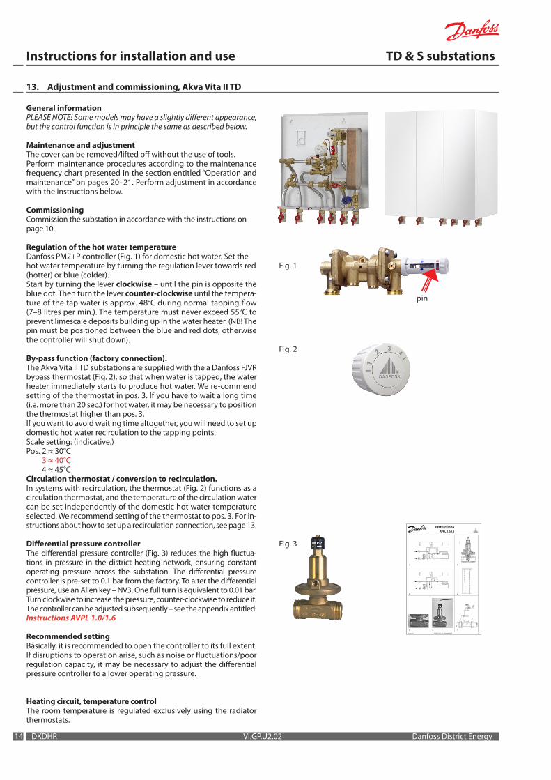
Regulation of the hot water temperatureDanfoss PM2+P controller (Fig. 1) for domestic hot water. Set the hot water temperature by turning the regulation lever towards red (hotter) or blue (colder). Start by turning the lever clockwise – until the pin is opposite the blue dot. Then turn the lever counter-clockwise until the tempera-ture of the tap water is approx. 48°C during normal tapping flow (7–8 litres per min.). The temperature must never exceed 55°C to prevent limescale deposits building up in the water heater. (NB! The pin must be positioned between the blue and red dots, otherwise the controller will shut down).
By-pass function (factory connection).The Akva Vita II TD substations are supplied with the a Danfoss FJVR bypass thermostat (Fig. 2), so that when water is tapped, the water heater immediately starts to produce hot water. We re-commend setting of the thermostat in pos. 3. If you have to wait a long time (i.e. more than 20 sec.) for hot water, it may be necessary to position the thermostat higher than pos. 3. If you want to avoid waiting time altogether, you will need to set up domestic hot water recirculation to the tapping points.Scale setting: (indicative.) Pos. 2 ≈ 30°C 3 ≈ 40°C 4 ≈ 45°CCirculation thermostat / conversion to recirculation.In systems with recirculation, the thermostat (Fig. 2) functions as a circulation thermostat, and the temperature of the circulation water can be set independently of the domestic hot water temperature selected. We recommend setting of the thermostat to pos. 3. For in-structions about how to set up a recirculation connection, see page 13.
Differential pressure controllerThe differential pressure controller (Fig. 3) reduces the high fluctua-tions in pressure in the district heating network, ensuring constant operating pressure across the substation. The differential pressure controller is pre-set to 0.1 bar from the factory. To alter the differential pressure, use an Allen key – NV3. One full turn is equivalent to 0.01 bar. Turn clockwise to increase the pressure, counter-clockwise to reduce it. The controller can be adjusted subsequently – see the appendix entitled:Instructions AVPL 1.0/1.6
Recommended settingBasically, it is recommended to open the controller to its full extent. If disruptions to operation arise, such as noise or fluctuations/poor regulation capacity, it may be necessary to adjust the differential pressure controller to a lower operating pressure.
Heating circuit, temperature controlThe room temperature is regulated exclusively using the radiator thermostats.
Fig. 1
Fig. 3
Fig. 2
1515
Instructions for installation and use TD & S substations
Danfoss District Energy VI.GP.U2.02 DKDHR
7369316-0 SIBC VI.CB.T1.6K © Danfoss 05/03 1
InstructionsAVPL 1.0/1.6
1 5
3 4 7
r kPa20 2519 2418 2317 2216 2115 2014 1913 1812 1711 1610 15
9 148 137 126 115 104 93 82 71 60 5
2 6
General informationPLEASE NOTE! Some models may have a slightly different appearance, but the control function is in principle the same as described below.
Service and adjustmentThe front insulation panel can be removed without the use of tools. Take hold of the air duct at the top and bottom on the right-hand side, and pull gently until the front section of the insulation releases from the rear section. Then pull the front section completely free. Perform maintenance procedures according to the maintenance frequency chart presented in the section entitled “Operation and maintenance” on pages 20–21. Perform adjustment in accordance with the instructions below.
CommissioningCommission the substation in accordance with the instructions on page 10.
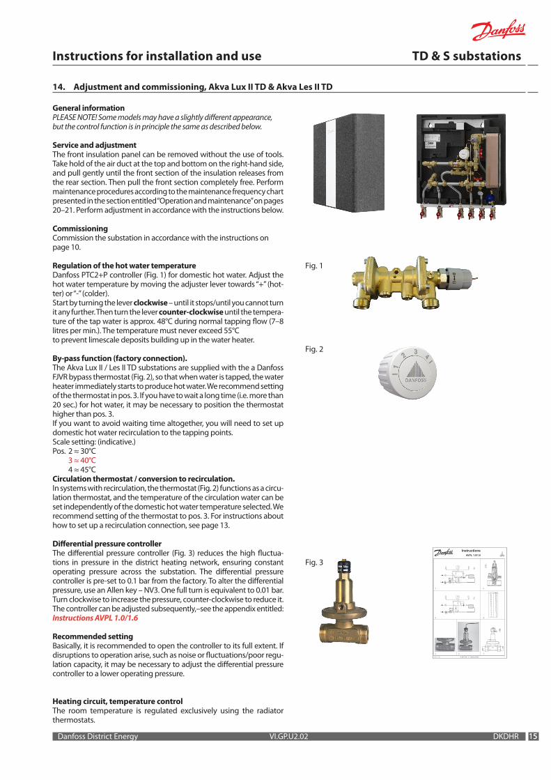
Regulation of the hot water temperatureDanfoss PTC2+P controller (Fig. 1) for domestic hot water. Adjust the hot water temperature by moving the adjuster lever towards “+” (hot-ter) or “-” (colder). Start by turning the lever clockwise – until it stops/until you cannot turn it any further. Then turn the lever counter-clockwise until the tempera-ture of the tap water is approx. 48°C during normal tapping flow (7–8 litres per min.). The temperature must never exceed 55°C to prevent limescale deposits building up in the water heater.
By-pass function (factory connection).The Akva Lux II / Les II TD substations are supplied with the a Danfoss FJVR bypass thermostat (Fig. 2), so that when water is tapped, the water heater immediately starts to produce hot water. We recommend setting of the thermostat in pos. 3. If you have to wait a long time (i.e. more than 20 sec.) for hot water, it may be necessary to position the thermostat higher than pos. 3. If you want to avoid waiting time altogether, you will need to set up domestic hot water recirculation to the tapping points.Scale setting: (indicative.) Pos. 2 ≈ 30°C 3 ≈ 40°C 4 ≈ 45°CCirculation thermostat / conversion to recirculation.In systems with recirculation, the thermostat (Fig. 2) functions as a circu-lation thermostat, and the temperature of the circulation water can be set independently of the domestic hot water temperature selected. We recommend setting of the thermostat to pos. 3. For instructions about how to set up a recirculation connection, see page 13.
Differential pressure controllerThe differential pressure controller (Fig. 3) reduces the high fluctua-tions in pressure in the district heating network, ensuring constant operating pressure across the substation. The differential pressure controller is pre-set to 0.1 bar from the factory. To alter the differential pressure, use an Allen key – NV3. One full turn is equivalent to 0.01 bar. Turn clockwise to increase the pressure, counter-clockwise to reduce it. The controller can be adjusted subsequently,–see the appendix entitled:Instructions AVPL 1.0/1.6
Recommended settingBasically, it is recommended to open the controller to its full extent. If disruptions to operation arise, such as noise or fluctuations/poor regu-lation capacity, it may be necessary to adjust the differential pressure controller to a lower operating pressure.
Heating circuit, temperature controlThe room temperature is regulated exclusively using the radiator thermostats.
14. Adjustment and commissioning, Akva Lux II TD & Akva Les II TD
Fig. 1
Fig. 3
Fig. 2
16
Instructions for installation and use TD & S substations
DKDHR VI.GP.U2.02 Danfoss District Energy
pin
7369316-0 SIBC VI.CB.T1.6K © Danfoss 05/03 1
InstructionsAVPL 1.0/1.6
1 5
3 4 7
r kPa20 2519 2418 2317 2216 2115 2014 1913 1812 1711 1610 15
9 148 137 126 115 104 93 82 71 60 5
2 6
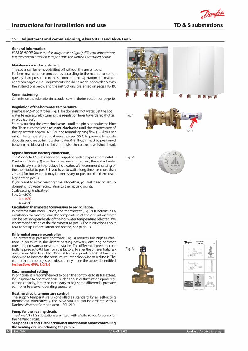
General informationPLEASE NOTE! Some models may have a slightly different appearance, but the control function is in principle the same as described below
Maintenance and adjustmentThe cover can be removed/lifted off without the use of tools. Perform maintenance procedures according to the maintenance fre-quency chart presented in the section entitled “Operation and mainte-nance” on pages 20–21. Adjustments should be made in accordance with the instructions below and the instructions presented on pages 18-19.
CommissioningCommission the substation in accordance with the instructions on page 10.
Regulation of the hot water temperatureDanfoss PM2+P controller (Fig. 1) for domestic hot water. Set the hot water temperature by turning the regulation lever towards red (hotter) or blue (colder). Start by turning the lever clockwise – until the pin is opposite the blue dot. Then turn the lever counter-clockwise until the temperature of the tap water is approx. 48°C during normal tapping flow (7–8 litres per min.). The temperature must never exceed 55°C to prevent limescale deposits building up in the water heater. (NB! The pin must be positioned between the blue and red dots, otherwise the controller will shut down).
Bypass function (factory connection).The Akva Vita II S substations are supplied with a bypass thermostat – Danfoss FJVR (Fig. 2) – so that when water is tapped, the water heater immediately starts to produce hot water. We recommend setting of the thermostat to pos. 3. If you have to wait a long time (i.e. more than 20 sec.) for hot water, it may be necessary to position the thermostat higher than pos. 3. If you want to avoid waiting time altogether, you will need to set up domestic hot water recirculation to the tapping points.Scale setting: (indicative.) Pos. 2 ≈ 30°C 3 ≈ 40°C 4 ≈ 45°CCirculation thermostat / conversion to recirculation.In systems with recirculation, the thermostat (Fig. 2) functions as a circulation thermostat, and the temperature of the circulation water can be set independently of the hot water temperature selected. We recommend setting of the thermostat to pos. 3. For instructions about how to set up a recirculation connection, see page 13.
Differential pressure controllerThe differential pressure controller (Fig. 3) reduces the high fluctua-tions in pressure in the district heating network, ensuring constant operating pressure across the substation. The differential pressure con-troller is pre-set to 0.1 bar from the factory. To alter the differential pres-sure, use an Allen key – NV3. One full turn is equivalent to 0.01 bar. Turn clockwise to increase the pressure, counter-clockwise to reduce it. The controller can be adjusted subsequently – see the appendix entitled Instructions AVPL 1.0/1.6
Recommended settingIn principle, it is recommended to open the controller to its full extent. If disruptions to operation arise, such as noise or fluctuations/poor reg-ulation capacity, it may be necessary to adjust the differential pressure controller to a lower operating pressure.
Heating circuit, temperture controlThe supply temperature is controlled as standard by an self-acting thermostat. Alternatively, the Akva Vita II S can be ordered with a Danfoss Weather Compensator – ECL 210.
Pump for the heating circuit.The Akva Vita II S substations are fitted with a Wilo Yonos A- pump for the heating circuit. See pages 18 and 19 for additional information about controlling the heating circuit, including the pump.
15. Adjustment and commissioning, Akva Vita II and Akva Les S
Fig. 1
Fig. 3
Fig. 2

1717
Instructions for installation and use TD & S substations
Danfoss District Energy VI.GP.U2.02 DKDHR
16. Adjustment and commissioning, Akva Lux II S & Akva Les II S
7369316-0 SIBC VI.CB.T1.6K © Danfoss 05/03 1
InstructionsAVPL 1.0/1.6
1 5
3 4 7
r kPa20 2519 2418 2317 2216 2115 2014 1913 1812 1711 1610 15
9 148 137 126 115 104 93 82 71 60 5
2 6
General informationPLEASE NOTE! Some models may have a slightly different appearance, but the control function is in principle the same as described below.
Service and adjustmentThe front insulation panel can be removed without the use of tools. Take hold of the air duct at the top and bottom on the right-hand side, and pull gently until the front section of the insulation releases from the rear section. Then pull the front section completely free. Perform maintenance procedures according to the maintenance fre-quency chart presented in the section entitled “Operation and mainte-nance” on pages 20–21. Adjustments should be made in accordance with the instructions below and the instructions presented on pages 18-19.
CommissioningCommission the substation in accordance with the instructions on page 10.
Regulation of the hot water temperatureDanfoss PTC2+P controller (Fig. 1) for domestic hot water. Adjust the hot water temperature by moving the adjuster lever towards “+” (hotter) or “-” (colder). Start by turning the lever clockwise – until it stops/until you cannot turn it any further. Then turn the lever coun-ter-clockwise until the temperature of the tap water is approx. 48°C during normal tapping flow (7–8 litres per min.). The temperature must never exceed 55°C to prevent limescale deposits building up in the water heater.
Bypass function (factory connection).The Akva Lux II / Les II S substations are supplied with a bypass thermo-stat – Danfoss FJVR (Fig. 2) – so that when water is tapped, the water heater immediately starts to produce hot water. We recommend setting the thermostat to pos. 3. If you have to wait a long time (i.e. more than 20 sec.) for the hot water, it may be necessary to set the thermostat to a position higher than pos. 3. If you want to avoid waiting time alto-gether, you will need to set up domestic hot water recirculation to the tapping points.Scale setting: (indicative.) Pos. 2 ≈ 30°C 3 ≈ 40°C 4 ≈ 45°CCirculation thermostat / conversion to recirculation.In systems with recirculation, the thermostat (Fig. 2) functions as a circula-tion thermostat, and the temperature of the circulation water can be set independently of the hot water temperature selected. We recommend setting of the thermostat to pos. 3. For instructions about how to set up a recirculation connection, see page 13.
Differential pressure controllerThe differential pressure controller (Fig. 3) reduces the high fluctua-tions in pressure in the district heating network, ensuring constant operating pressure across the substation. The differential pressure controller is pre-set to 0.1 bar from the factory. To alter the differential pressure, use an Allen key – NV3. One full turn is equivalent to 0.01 bar. Turn clockwise to increase the pressure, counter-clockwise to reduce it. The controller can be adjusted subsequently – see the appendix enti-tled Instructions AVPL 1.0/1.6 Recommended settingIn principle, it is recommended to open the controller to its full extent. If disruptions to operation arise, such as noise or fluctuations/poor reg-ulation capacity, it may be necessary to adjust the differential pressure controller to a lower operating pressure.Heating circuit, temperature controlThe supply temperature is controlled as standard by an self-acting thermostat. Alternatively, the Akva Lux II /Les II S can be ordered with a Danfoss Weather Compensator – ECL 210.
Pump for the heating circuit.The Akva Lux II / Les II S substations are fitted with an Alpha2, A-pump for the heating circuit. See pages 18 and 19 for additional informa-tion about controlling the heating circuit, including the pump.
Fig. 1
Fig. 3
Fig. 2
or
InstructionsAMV 150
73691180 DH-SMT/SI VI.KU.N2.1J © Danfoss 01/2008 1
ENglIsh Actuators for three point control AMV 150 www.danfoss.com Page 2
DANsK Motorer til 3-punkts styring AMV 150 www.danfoss.dk Side 3
DEUTsCh Stellantriebe für 3-Pkt.- Eingangssignal AMV 150 www.danfoss.de Seite 3
sVENsKA Motor för 3-punktsreglering AMV 150 varme.danfoss.se Sida 4
NEDERlANDs Servomotor met 3-puntssturing AMV 150 www.danfoss.nl Pagina 4
lIETUVIŲ K. Pavaros trijų padėčių valdymui AMV 150 www.danfoss.lt 5 puslapis
lATVIsKI Motori trīs punktu kontrolei AMV 150 www.danfoss.com Lpp. 5
MAgYAR Szelepmozgatók hárompontos szabályozáshoz AMV 150 www.danfoss.com 6. oldal
ČEsKY Servopohony s tříbodovým regulačním signálem AMV 150 www.danfoss.cz Strana 6
POlsKI Siłowniki sterowane sygnałem 3-punktowym AMV 150 www.danfoss.pl Strona 7
РУССКИЙ Электроприводы для трехпозиционного регулирования AMV 150 www.danfoss.ru Страница 7
AMV 150 + AMV 150 + AMV 150 + VS2 (DN 15) VMV AVQM (DN 15)
Akva Lux II S with electronic controller Danfoss ECL 210
7369267-9 SIBC R&D EI.97.Q2.00 © Danfoss 12/01 1
INSTRUCTIONSVS2 2-way
065R
9075
065R
9075
DN L (mm)15 6520 7025 75
DN L1 (mm)15 13120 14225 159
DN L2 (mm)15 13920 15425 159
DN L3 (mm)15 6920 7425 79
18
Instructions for installation and use TD & S substations
DKDHR VI.GP.U2.02 Danfoss District Energy
17. Adjustment and commissioning of S substations, heating circuit
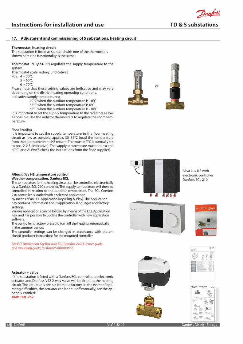
Thermostat, heating circuitThe substation is fitted as standard with one of the thermostats shown here (the functionality is the same)
Thermostat T°C (pos. 11) regulates the supply temperature to the system.Thermostat scale setting: (indicative.)Pos. 4 ≈ 50°C 5 ≈ 60°C 6 ≈ 70°CPlease note that these setting values are indicative and may vary depending on the district heating operating conditions. Indicative supply temperatures: 40°C when the outdoor temperature is 10°C 55°C when the outdoor temperature is 0°C 65°C when the outdoor temperature is -10°CIt is important to set the supply temperature to the radiators as low as possible. Use the radiator thermostats to regulate the room tem-perature.
Floor heating It is important to set the supply temperature to the floor heating circuit as low as possible, approx. 30–35°C (read the temperature from the thermometer on HE return). Thermostat T°C is normally set to pos. 2-2.5 (indicative). The supply temperature must not exceed 40°C (and ALWAYS check the instructions from the floor supplier).
Alternative HE temperature controlWeather compensation, Danfoss ECLThe temperature for the heating circuit can be controlled electronicallyby a Danfoss ECL 210 controller. The supply temperature will then be controlled in relation to the outdoor temperature. The ECL Comfort 210 controller is loaded with a selected applicationby means of an ECL Application Key (Plug-&-Play). The ApplicationKey contains information about application, languages and factorysettings.Various applications can be loaded by means of the ECL ApplicationKey, and it is possible to update the controller with new applicationsoftware.The controller is factory preset to turn off the heating automaticallyin the summer period.The controller settings can be changed in accordance with the en-closed producer instructions for the mounted controller.
See ECL Application Key Box with ECL Comfort 210/310 user guideand mounting guide, for further information.
Actuator + valveIf the substation is fitted with a Danfoss ECL controller, an electronic actuator and Danfoss VS2 2-way valve will be fitted to the heating circuit. The actuator is pre-set from the factory. In the event of ope-rating difficulties, the actuator can be shut off manually, see the ap-pendix entitled:AMV 150, VS2
Variable pressureMax. pos.
VentingVertical pos.
Constant pressureMax. pos.
Wilo Yonos PARA
1919
Instructions for installation and use TD & S substations
Danfoss District Energy VI.GP.U2.02 DKDHR
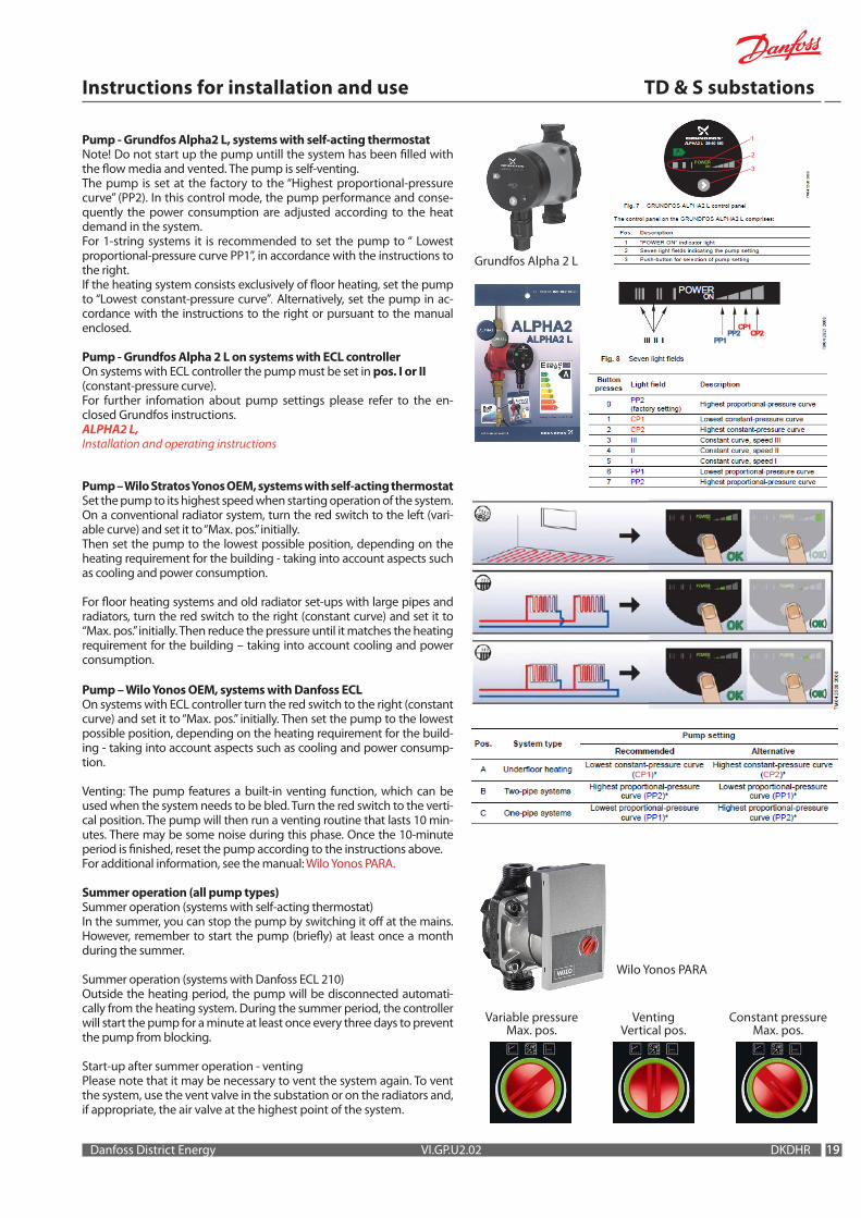
Pump - Grundfos Alpha2 L, systems with self-acting thermostatNote! Do not start up the pump untill the system has been filled with the flow media and vented. The pump is self-venting.The pump is set at the factory to the “Highest proportional-pressure curve” (PP2). In this control mode, the pump performance and conse-quently the power consumption are adjusted according to the heat demand in the system.For 1-string systems it is recommended to set the pump to “ Lowest proportional-pressure curve PP1”, in accordance with the instructions to the right. If the heating system consists exclusively of floor heating, set the pump to “Lowest constant-pressure curve”. Alternatively, set the pump in ac-cordance with the instructions to the right or pursuant to the manual enclosed.
Pump - Grundfos Alpha 2 L on systems with ECL controllerOn systems with ECL controller the pump must be set in pos. I or II (constant-pressure curve).For further infomation about pump settings please refer to the en-closed Grundfos instructions.ALPHA2 L, Installation and operating instructions
Pump – Wilo Stratos Yonos OEM, systems with self-acting thermostatSet the pump to its highest speed when starting operation of the system. On a conventional radiator system, turn the red switch to the left (vari-able curve) and set it to “Max. pos.” initially. Then set the pump to the lowest possible position, depending on the heating requirement for the building - taking into account aspects such as cooling and power consumption.
For floor heating systems and old radiator set-ups with large pipes and radiators, turn the red switch to the right (constant curve) and set it to “Max. pos.” initially. Then reduce the pressure until it matches the heating requirement for the building – taking into account cooling and power consumption.
Pump – Wilo Yonos OEM, systems with Danfoss ECLOn systems with ECL controller turn the red switch to the right (constant curve) and set it to “Max. pos.” initially. Then set the pump to the lowest possible position, depending on the heating requirement for the build-ing - taking into account aspects such as cooling and power consump-tion.
Venting: The pump features a built-in venting function, which can be used when the system needs to be bled. Turn the red switch to the verti-cal position. The pump will then run a venting routine that lasts 10 min-utes. There may be some noise during this phase. Once the 10-minute period is finished, reset the pump according to the instructions above.For additional information, see the manual: Wilo Yonos PARA.
Summer operation (all pump types)Summer operation (systems with self-acting thermostat)In the summer, you can stop the pump by switching it off at the mains. However, remember to start the pump (briefly) at least once a month during the summer.
Summer operation (systems with Danfoss ECL 210)Outside the heating period, the pump will be disconnected automati-cally from the heating system. During the summer period, the controller will start the pump for a minute at least once every three days to prevent the pump from blocking.
Start-up after summer operation - ventingPlease note that it may be necessary to vent the system again. To vent the system, use the vent valve in the substation or on the radiators and, if appropriate, the air valve at the highest point of the system.
Grundfos Alpha 2 L

20
Instructions for installation and use TD & S substations
DKDHR VI.GP.U2.02 Danfoss District Energy
18. Operation and maintenance
Operation and maintenanceThe caretaker/owner must perform visual checking and reading of the district heating meter at short, regular intervals. (The meter is not a part of the delivery from Danfoss).Service procedures must only be performed by trained, authorised personnel.NB! Excessive consumption for whatever reason is not covered by the Danfoss warranty.
Service The substation should be checked regularly by authorised person-nel. Any necessary maintenance must be performed in accordance with the instructions in this manual and other sets of instructions. During service the dirt strainers are to be cleaned (pos. 8 – including the filter (F) on the controller, see the photo to the right), all pipe connections must be tightened and the safety valve (pos. 5) must be function tested by turning the lever.
Rinsing / Return rinsingTo clean the plate heat exchanger, rinse it by running clean water through the exchanger at high speed and in the opposite direction to the normal flow. This will remove any dirt deposits that may have built up in the exchanger. If rinsing with clean water is not sufficient, the exchanger can also be cleaned by circulating a cleaning agent approved by Danfoss (e.g. Kaloxi cleaning fluid) through the exchanger. Kaloxi cleaning fluid is environmentally friendly and can be disposed off through the standard sewer system. After use of a cleaning fluid, the plate heat exchanger must be rinsed thoroughly with clean water.
Acid cleaning of brazed plate heat exhangerIn principle, we do not recommend using acid cleaning of the plate heat exchanger. Deposits of limescale may build up in plate heat ex-changers for domestic hot water on account of the large temperature fluctuations, and because aerated water is used on the secondary side. If it becomes necessary to clean the exchanger with acid, this can be done as shown in the figure to the right. Brazed plate heat exchangers can withstand rinsing with a dilute acid solution – e.g. 5% formic acid.
Measures after maintenance workAfter maintenance work and before commissioning:• Tighten all pipe connections• Replace insulation covers on heat exchangers and other
insulated equipment• Wipe down the substation and clean up any fluid spills• Clear all tools, materials and other equipment from the work area• Switch on the energy supply and check for leakage• Vent the system• Carry out any necessary adjustments again.• Check that pressure and temperature are at normal levels.
Cooling / Reading the return temperatureCooling – i.e. the difference between the supply and return tempera-ture of the district heating water – has a significant effect on overall energy economy. Therefore, it is important to focus on the supply and return temperature in the heating system. The difference should typically be 30–35°C. Please note that a low district heating return temperature is directly related to the return temperature from the heating circuit and the return temperature of the circulation water. It is therefore important to focus on these return temperatures.
Cooling from the water heater alone:During tapping, the level of cooling will typically be 30–35°C. When hot water is not being tapped, it is completely normal for the return temperature from the water heater to rise slightly. In this situation, the district heating meter will register very modest consumption as the volume of water is very small. On water heaters with recirculation, the calorie meter registers the heat loss in the circulation pipe.
2121
Instructions for installation and use TD & S substations
Danfoss District Energy VI.GP.U2.02 DKDHR
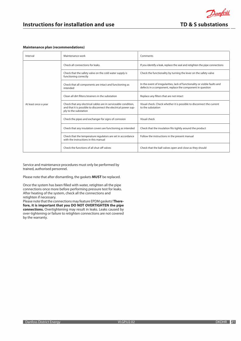
Maintenance plan (recommendations)
Service and maintenance procedures must only be performed by trained, authorised personnel.
Please note that after dismantling, the gaskets MuST be replaced.
Once the system has been filled with water, retighten all the pipe connections once more before performing pressure test for leaks.After heating of the system, check all the connections and retighten if necessary.Please note that the connections may feature EPDM gaskets! There-fore, it is important that you DO NOT OVERTIGHTEN the pipe connections. Overtightening may result in leaks. Leaks caused by over-tightening or failure to retighten connections are not covered by the warranty.
Interval Maintenance work Comments
At least once a year
Check all connections for leaks. If you identify a leak, replace the seal and retighten the pipe connections
Check that the safety valve on the cold water supply is functioning correctly
Check the functionality by turning the lever on the safety valve
Check that all components are intact and functioning as intended
In the event of irregularities, lack of functionality or visible faults and defects in a component, replace the component in question
Clean all dirt filters/strainers in the substation Replace any filters that are not intact
Check that any electrical cables are in serviceable condition, and that it is possible to disconnect the electrical power sup-ply to the substation
Visual check. Check whether it is possible to disconnect the current to the substation
Check the pipes and exchanger for signs of corrosion Visual check
Check that any insulation covers are functioning as intended Check that the insulation fits tightly around the product
Check that the temperature regulators are set in accordance with the instructions in this manual
Follow the instructions in the present manual
Check the functions of all shut-off valves Check that the ball valves open and close as they should
22
Instructions for installation and use TD & S substations
DKDHR VI.GP.U2.02 Danfoss District Energy
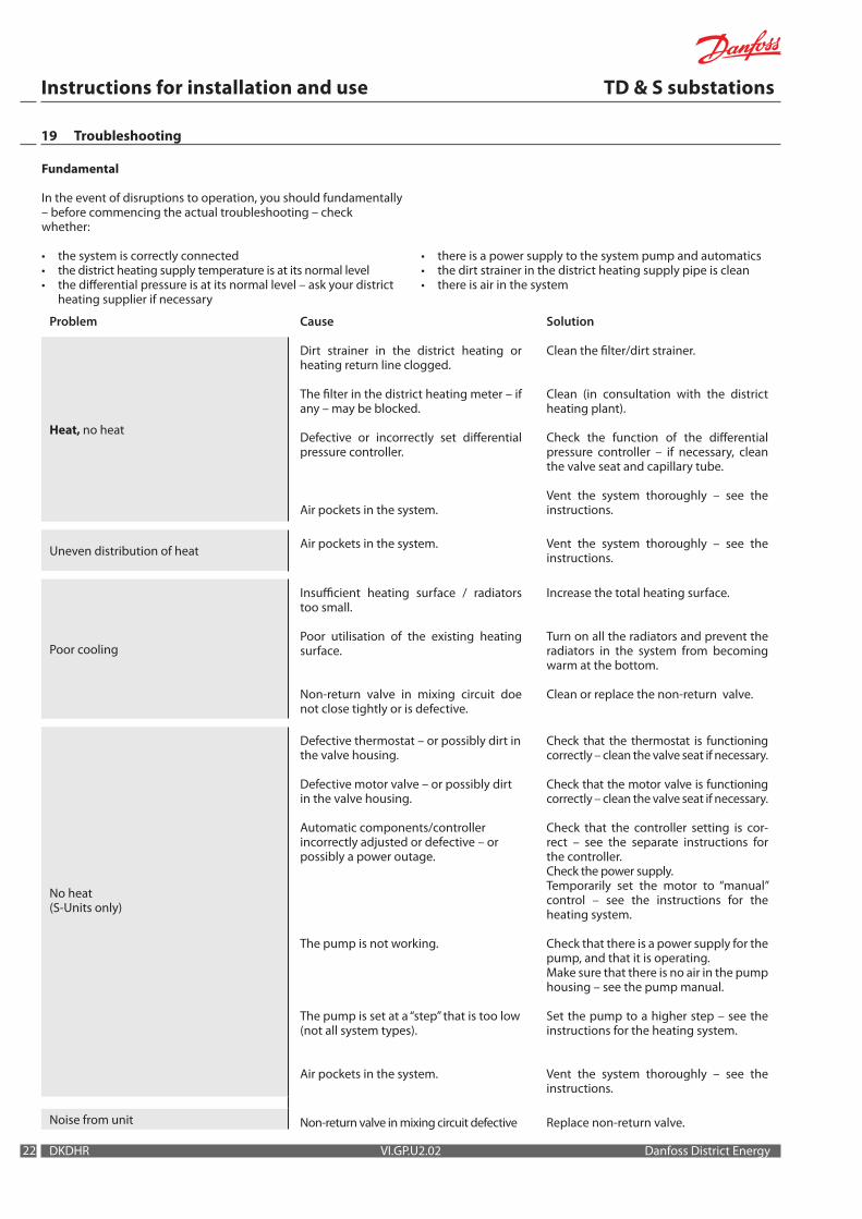
19 Troubleshooting
Problem Cause Solution
Heat, no heat
Dirt strainer in the district heating or heating return line clogged.
The filter in the district heating meter – if any – may be blocked.
Defective or incorrectly set differential pressure controller.
Air pockets in the system.
Clean the filter/dirt strainer.
Clean (in consultation with the district heating plant).
Check the function of the differential pressure controller – if necessary, clean the valve seat and capillary tube.
Vent the system thoroughly – see the instructions.
Uneven distribution of heat Air pockets in the system. Vent the system thoroughly – see the instructions.
Poor cooling
Insufficient heating surface / radiators too small.
Poor utilisation of the existing heating surface.
Non-return valve in mixing circuit doe not close tightly or is defective.
Increase the total heating surface.
Turn on all the radiators and prevent the radiators in the system from becoming warm at the bottom.
Clean or replace the non-return valve.
No heat (S-Units only)
Defective thermostat – or possibly dirt in the valve housing.
Defective motor valve – or possibly dirt in the valve housing.
Automatic components/controller incorrectly adjusted or defective – or possibly a power outage.
The pump is not working.
The pump is set at a “step” that is too low (not all system types).
Air pockets in the system.
Check that the thermostat is functioning correctly – clean the valve seat if necessary.
Check that the motor valve is functioning correctly – clean the valve seat if necessary.
Check that the controller setting is cor-rect – see the separate instructions for the controller.Check the power supply. Temporarily set the motor to “manual” control – see the instructions for the heating system.
Check that there is a power supply for the pump, and that it is operating.Make sure that there is no air in the pump housing – see the pump manual.
Set the pump to a higher step – see the instructions for the heating system.
Vent the system thoroughly – see the instructions.
Noise from unit Non-return valve in mixing circuit defective Replace non-return valve.
Fundamental
In the event of disruptions to operation, you should fundamentally – before commencing the actual troubleshooting – checkwhether:
• the system is correctly connected• the district heating supply temperature is at its normal level• the differential pressure is at its normal level – ask your district
heating supplier if necessary
• there is a power supply to the system pump and automatics • the dirt strainer in the district heating supply pipe is clean• there is air in the system
2323
Instructions for installation and use TD & S substations
Danfoss District Energy VI.GP.U2.02 DKDHR
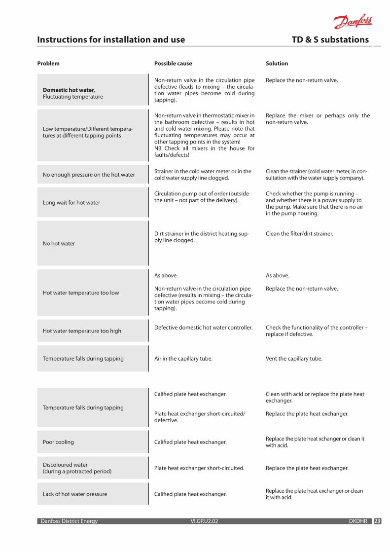
Problem Possible cause Solution
Domestic hot water, Fluctuating temperature
Non-return valve in the circulation pipe defective (leads to mixing – the circula-tion water pipes become cold during tapping).
Replace the non-return valve.
Low temperature/Different tempera-tures at different tapping points
Non-return valve in thermostatic mixer in the bathroom defective – results in hot and cold water mixing. Please note that fluctuating temperatures may occur at other tapping points in the system!NB Check all mixers in the house for faults/defects!
Replace the mixer or perhaps only the non-return valve.
No enough pressure on the hot water Strainer in the cold water meter or in the cold water supply line clogged.
Clean the strainer (cold water meter, in con-sultation with the water supply company).
Long wait for hot water
Circulation pump out of order (outside the unit – not part of the delivery).
Check whether the pump is running – and whether there is a power supply to the pump. Make sure that there is no air in the pump housing.
No hot water
Dirt strainer in the district heating sup-ply line clogged.
Clean the filter/dirt strainer.
Hot water temperature too low
As above.
Non-return valve in the circulation pipe defective (results in mixing – the circula-tion water pipes become cold during tapping).
As above.
Replace the non-return valve.
Hot water temperature too high Defective domestic hot water controller. Check the functionality of the controller – replace if defective.
Temperature falls during tapping Air in the capillary tube. Vent the capillary tube.
Temperature falls during tapping
Calified plate heat exchanger.
Plate heat exchanger short-circuited/defective.
Clean with acid or replace the plate heat exchanger.
Replace the plate heat exchanger.
Poor cooling Calified plate heat exchanger. Replace the plate heat xchanger or clean it with acid.
Discoloured water (during a protracted period) Plate heat exchanger short-circuited. Replace the plate heat exchanger.
Lack of hot water pressure Calified plate heat exchanger. Replace the plate heat exchanger or clean it with acid.
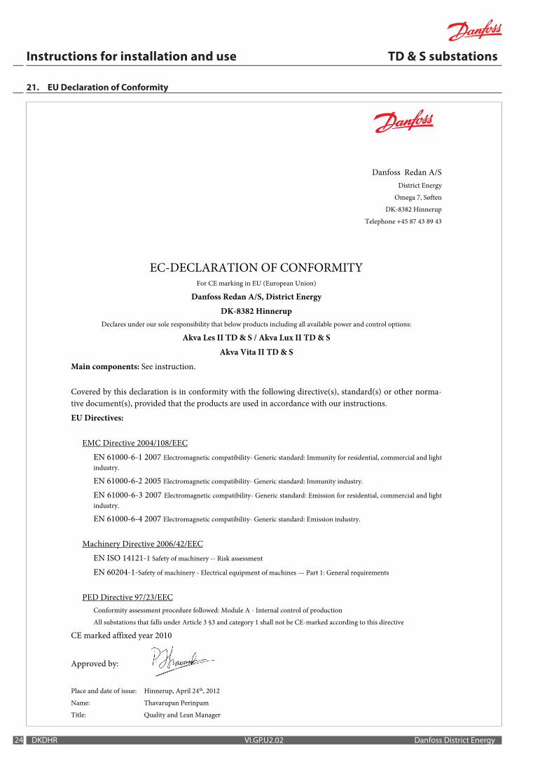
24
Danfoss Redan A/S District Energy
Omega 7, Søften DK-8382 Hinnerup
Telephone +45 87 43 89 43
EC-DECLARATION OF CONFORMITY
For CE marking in EU (European Union)
Danfoss Redan A/S, District Energy DK-8382 Hinnerup
Declares under our sole responsibility that below products including all available power and control options:
Akva Les II TD & S / Akva Lux II TD & S Akva Vita II TD & S
Main components: See instruction.
Covered by this declaration is in conformity with the following directive(s), standard(s) or other norma-tive document(s), provided that the products are used in accordance with our instructions. EU Directives:
EMC Directive 2004/108/EEC EN 61000-6-1 2007 Electromagnetic compatibility- Generic standard: Immunity for residential, commercial and light industry.
EN 61000-6-2 2005 Electromagnetic compatibility- Generic standard: Immunity industry. EN 61000-6-3 2007 Electromagnetic compatibility- Generic standard: Emission for residential, commercial and light industry. EN 61000-6-4 2007 Electromagnetic compatibility- Generic standard: Emission industry.
Machinery Directive 2006/42/EEC EN ISO 14121-1 Safety of machinery -- Risk assessment
EN 60204-1-Safety of machinery - Electrical equipment of machines — Part 1: General requirements
PED Directive 97/23/EEC Conformity assessment procedure followed: Module A - Internal control of production All substations that falls under Article 3 §3 and category 1 shall not be CE-marked according to this directive
CE marked affixed year 2010 Approved by: Place and date of issue: Hinnerup, April 24th, 2012 Name: Thavarupan Perinpam
Title: Quality and Lean Manager
Instructions for installation and use TD & S substations
DKDHR VI.GP.U2.02 Danfoss District Energy
21. Eu Declaration of Conformity

2525Danfoss District Energy VI.GP.U2.02 DKDHR
22. Commissioning certificate
Commissioning certificateThe substation is the direct link between the district heating supply network and the household piping system. All supply pipes and the pipes in the household piping system must be checked and rinsed before commissioning. Once the system has been filled with water, all pipe connections must be retightened before performing pressure test for leaks. The dirt strainers must be cleaned and the substation must be adjusted in accordance with the instructions in this manual.
It is important to comply with all technical regulations and the applicable legislation in every respect.
Installation and commissioning must only be performed by trained, authorised personnel.
The substation is checked in the factory for leaks before delivery. Leaks are however possible due to vibrations caused by transport, hand-ling and heating of the system and therefore it is important to check all connections and to retighten if necessarys before commissioning.Please note that the connections may feature EPDM gaskets! Therefore it is important that you DO NOT OVER-TIGHTEN the connections. Over-tightening may result in leaks. Leaks caused by overtightening or failure to retighten connections are not covered by the warranty.
To be filled-out by the installer.
This substation has been retightened, adjusted and commissioned
on the: by Installer:
Date/Year Company name (stamp)

26 DKDHR VI.GP.U2.02 Danfoss District Energy

2727Danfoss District Energy VI.GP.U2.02 DKDHR
Produced by Danfoss Redan A/S © 06/2012VI.GP.U2.02
Danfoss Redan A/S · District Energy · Omega 7, Søften · DK-8382 HinnerupTel. +45 87 43 89 43 · Fax: +45 87 43 89 44 · [email protected] · www.redan.danfoss.dk