
AKM - Intelligent Systems Laboratoryisl.ecst.csuchico.edu/DOCS/Logs/Shane/eATV/AKM manual.pdf ·...
46
AKM Synchronous Servomotors Product Manual Edition 09/2007 File akm_e.*** Keep all manuals as a product component during the life span of the product. Pass all manuals to future users / owners of the product.
Transcript of AKM - Intelligent Systems Laboratoryisl.ecst.csuchico.edu/DOCS/Logs/Shane/eATV/AKM manual.pdf ·...
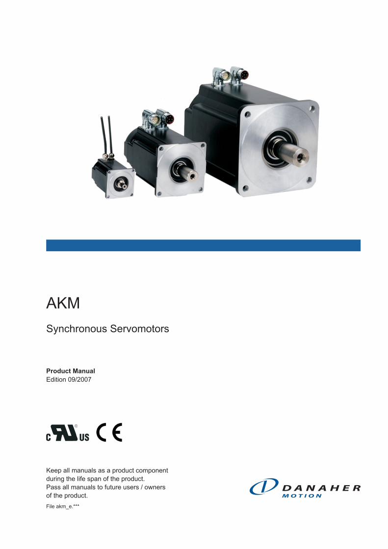
AKM
Synchronous Servomotors
Product Manual
Edition 09/2007
File akm_e.***
Keep all manuals as a product component
during the life span of the product.
Pass all manuals to future users / owners
of the product.
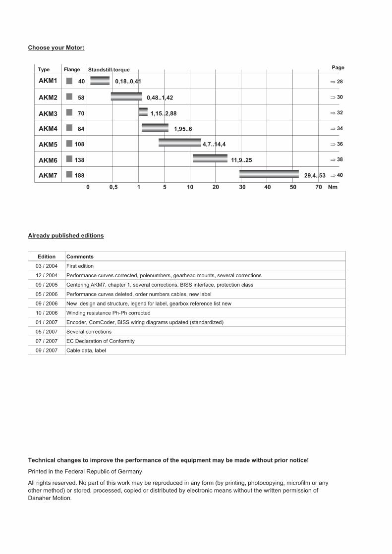
Choose your Motor:
Already published editions
Edition Comments
03 / 2004 First edition
12 / 2004 Performance curves corrected, polenumbers, gearhead mounts, several corrections
09 / 2005 Centering AKM7, chapter 1, several corrections, BISS interface, protection class
05 / 2006 Performance curves deleted, order numbers cables, new label
09 / 2006 New design and structure, legend for label, gearbox reference list new
10 / 2006 Winding resistance Ph-Ph corrected
01 / 2007 Encoder, ComCoder, BISS wiring diagrams updated (standardized)
05 / 2007 Several corrections
07 / 2007 EC Declaration of Conformity
09 / 2007 Cable data, label
Technical changes to improve the performance of the equipment may be made without prior notice!
Printed in the Federal Republic of Germany
All rights reserved. No part of this work may be reproduced in any form (by printing, photocopying, microfilm or any
other method) or stored, processed, copied or distributed by electronic means without the written permission of
Danaher Motion.
0,5
40 0,18..0,41
58 0,48..1,42
70 1,15..2,88
84 1,95..6
108 4,7..14,4
138 11,9..25
188 29,4..53
0 10 5020 701 305 40 Nm
Flange Standstill torque Page
� 28
� 30
� 32
� 34
� 36
� 38
� 40
AKM1
AKM7
AKM6
AKM5
AKM4
AKM3
AKM2
Type
New Table of Contents
1 General
1.1 About this manual . . . . . . . . . . . . . . . . . . . . . . . . . . . . . . . . . . . . . . . . . . . . . . . . . . . . . . . . . . . . . . . . . . . . . . . 5
1.2 Symbols used. . . . . . . . . . . . . . . . . . . . . . . . . . . . . . . . . . . . . . . . . . . . . . . . . . . . . . . . . . . . . . . . . . . . . . . . . . . 5
1.3 Abbreviations used. . . . . . . . . . . . . . . . . . . . . . . . . . . . . . . . . . . . . . . . . . . . . . . . . . . . . . . . . . . . . . . . . . . . . . . 5
2 Safety
2.1 Safety Notes . . . . . . . . . . . . . . . . . . . . . . . . . . . . . . . . . . . . . . . . . . . . . . . . . . . . . . . . . . . . . . . . . . . . . . . . . . . 6
2.2 Use as directed . . . . . . . . . . . . . . . . . . . . . . . . . . . . . . . . . . . . . . . . . . . . . . . . . . . . . . . . . . . . . . . . . . . . . . . . . 7
3 Standards
3.1 EC Declaration of Conformity. . . . . . . . . . . . . . . . . . . . . . . . . . . . . . . . . . . . . . . . . . . . . . . . . . . . . . . . . . . . . . . 8
4 Handling
4.1 Transport . . . . . . . . . . . . . . . . . . . . . . . . . . . . . . . . . . . . . . . . . . . . . . . . . . . . . . . . . . . . . . . . . . . . . . . . . . . . . . 9
4.2 Packaging . . . . . . . . . . . . . . . . . . . . . . . . . . . . . . . . . . . . . . . . . . . . . . . . . . . . . . . . . . . . . . . . . . . . . . . . . . . . . 9
4.3 Storage . . . . . . . . . . . . . . . . . . . . . . . . . . . . . . . . . . . . . . . . . . . . . . . . . . . . . . . . . . . . . . . . . . . . . . . . . . . . . . . 9
4.4 Maintenance / Cleaning . . . . . . . . . . . . . . . . . . . . . . . . . . . . . . . . . . . . . . . . . . . . . . . . . . . . . . . . . . . . . . . . . . . 9
4.5 Disposal . . . . . . . . . . . . . . . . . . . . . . . . . . . . . . . . . . . . . . . . . . . . . . . . . . . . . . . . . . . . . . . . . . . . . . . . . . . . . . . 9
5 Package
5.1 Delivery package . . . . . . . . . . . . . . . . . . . . . . . . . . . . . . . . . . . . . . . . . . . . . . . . . . . . . . . . . . . . . . . . . . . . . . . 10
5.2 Nameplate . . . . . . . . . . . . . . . . . . . . . . . . . . . . . . . . . . . . . . . . . . . . . . . . . . . . . . . . . . . . . . . . . . . . . . . . . . . . 10
5.3 Model number description . . . . . . . . . . . . . . . . . . . . . . . . . . . . . . . . . . . . . . . . . . . . . . . . . . . . . . . . . . . . . . . . 11
6 Technical Description
6.1 Design of the motors . . . . . . . . . . . . . . . . . . . . . . . . . . . . . . . . . . . . . . . . . . . . . . . . . . . . . . . . . . . . . . . . . . . . 12
6.2 General technical data . . . . . . . . . . . . . . . . . . . . . . . . . . . . . . . . . . . . . . . . . . . . . . . . . . . . . . . . . . . . . . . . . . . 12
6.3 Standard features. . . . . . . . . . . . . . . . . . . . . . . . . . . . . . . . . . . . . . . . . . . . . . . . . . . . . . . . . . . . . . . . . . . . . . . 13
6.3.1 Style. . . . . . . . . . . . . . . . . . . . . . . . . . . . . . . . . . . . . . . . . . . . . . . . . . . . . . . . . . . . . . . . . . . . . . . . . . . . 13
6.3.2 Shaft end, A-side . . . . . . . . . . . . . . . . . . . . . . . . . . . . . . . . . . . . . . . . . . . . . . . . . . . . . . . . . . . . . . . . . . 13
6.3.3 Flange . . . . . . . . . . . . . . . . . . . . . . . . . . . . . . . . . . . . . . . . . . . . . . . . . . . . . . . . . . . . . . . . . . . . . . . . . . 13
6.3.4 Protection class . . . . . . . . . . . . . . . . . . . . . . . . . . . . . . . . . . . . . . . . . . . . . . . . . . . . . . . . . . . . . . . . . . . 13
6.3.5 Protective device . . . . . . . . . . . . . . . . . . . . . . . . . . . . . . . . . . . . . . . . . . . . . . . . . . . . . . . . . . . . . . . . . . 13
6.3.6 Insulation material class. . . . . . . . . . . . . . . . . . . . . . . . . . . . . . . . . . . . . . . . . . . . . . . . . . . . . . . . . . . . . 13
6.3.7 Vibration class . . . . . . . . . . . . . . . . . . . . . . . . . . . . . . . . . . . . . . . . . . . . . . . . . . . . . . . . . . . . . . . . . . . . 14
6.3.8 Connection method . . . . . . . . . . . . . . . . . . . . . . . . . . . . . . . . . . . . . . . . . . . . . . . . . . . . . . . . . . . . . . . . 14
6.3.9 Feedback unit . . . . . . . . . . . . . . . . . . . . . . . . . . . . . . . . . . . . . . . . . . . . . . . . . . . . . . . . . . . . . . . . . . . . 14
6.3.10 Holding brake. . . . . . . . . . . . . . . . . . . . . . . . . . . . . . . . . . . . . . . . . . . . . . . . . . . . . . . . . . . . . . . . . . . . . 14
6.3.11 Pole numbers. . . . . . . . . . . . . . . . . . . . . . . . . . . . . . . . . . . . . . . . . . . . . . . . . . . . . . . . . . . . . . . . . . . . . 14
6.4 Options. . . . . . . . . . . . . . . . . . . . . . . . . . . . . . . . . . . . . . . . . . . . . . . . . . . . . . . . . . . . . . . . . . . . . . . . . . . . . . . 15
6.5 Selection criteria. . . . . . . . . . . . . . . . . . . . . . . . . . . . . . . . . . . . . . . . . . . . . . . . . . . . . . . . . . . . . . . . . . . . . . . . 15
7 Mechanical Installation
7.1 Important Notes . . . . . . . . . . . . . . . . . . . . . . . . . . . . . . . . . . . . . . . . . . . . . . . . . . . . . . . . . . . . . . . . . . . . . . . . 16
8 Electrical Installation
8.1 Safety notes . . . . . . . . . . . . . . . . . . . . . . . . . . . . . . . . . . . . . . . . . . . . . . . . . . . . . . . . . . . . . . . . . . . . . . . . . . . 17
8.2 Guide for electrical installation . . . . . . . . . . . . . . . . . . . . . . . . . . . . . . . . . . . . . . . . . . . . . . . . . . . . . . . . . . . . . 18
8.3 Connection of the motors with preassembled cables. . . . . . . . . . . . . . . . . . . . . . . . . . . . . . . . . . . . . . . . . . . . 18
8.4 Wiring diagrams . . . . . . . . . . . . . . . . . . . . . . . . . . . . . . . . . . . . . . . . . . . . . . . . . . . . . . . . . . . . . . . . . . . . . . . . 19
8.4.1 Wiring diagram for motors with Resolver . . . . . . . . . . . . . . . . . . . . . . . . . . . . . . . . . . . . . . . . . . . . . . . . 19
8.4.2 Wiring diagram for motors with Encoder . . . . . . . . . . . . . . . . . . . . . . . . . . . . . . . . . . . . . . . . . . . . . . . . 20
8.4.3 Wiring diagram for motors with SFD . . . . . . . . . . . . . . . . . . . . . . . . . . . . . . . . . . . . . . . . . . . . . . . . . . . 21
8.4.4 Wiring diagram for motors with ComCoder . . . . . . . . . . . . . . . . . . . . . . . . . . . . . . . . . . . . . . . . . . . . . . 22
8.4.5 Wiring diagram for motors with BISS . . . . . . . . . . . . . . . . . . . . . . . . . . . . . . . . . . . . . . . . . . . . . . . . . . . 23
9 Setup
9.1 Important notes . . . . . . . . . . . . . . . . . . . . . . . . . . . . . . . . . . . . . . . . . . . . . . . . . . . . . . . . . . . . . . . . . . . . . . . . 25
9.2 Guide for setup. . . . . . . . . . . . . . . . . . . . . . . . . . . . . . . . . . . . . . . . . . . . . . . . . . . . . . . . . . . . . . . . . . . . . . . . . 25
9.3 Trouble Shooting . . . . . . . . . . . . . . . . . . . . . . . . . . . . . . . . . . . . . . . . . . . . . . . . . . . . . . . . . . . . . . . . . . . . . . . 26
Servomotors AKM 3
Danaher Motion 09/2007 Contents
Page
10 Technical Data
10.1 Definition of Terms. . . . . . . . . . . . . . . . . . . . . . . . . . . . . . . . . . . . . . . . . . . . . . . . . . . . . . . . . . . . . . . . . . . . . . 27
10.2 AKM1 . . . . . . . . . . . . . . . . . . . . . . . . . . . . . . . . . . . . . . . . . . . . . . . . . . . . . . . . . . . . . . . . . . . . . . . . . . . . . . . . 28
10.3 AKM2 . . . . . . . . . . . . . . . . . . . . . . . . . . . . . . . . . . . . . . . . . . . . . . . . . . . . . . . . . . . . . . . . . . . . . . . . . . . . . . . . 30
10.4 AKM3 . . . . . . . . . . . . . . . . . . . . . . . . . . . . . . . . . . . . . . . . . . . . . . . . . . . . . . . . . . . . . . . . . . . . . . . . . . . . . . . . 32
10.5 AKM4 . . . . . . . . . . . . . . . . . . . . . . . . . . . . . . . . . . . . . . . . . . . . . . . . . . . . . . . . . . . . . . . . . . . . . . . . . . . . . . . . 34
10.6 AKM5 . . . . . . . . . . . . . . . . . . . . . . . . . . . . . . . . . . . . . . . . . . . . . . . . . . . . . . . . . . . . . . . . . . . . . . . . . . . . . . . . 36
10.7 AKM6 . . . . . . . . . . . . . . . . . . . . . . . . . . . . . . . . . . . . . . . . . . . . . . . . . . . . . . . . . . . . . . . . . . . . . . . . . . . . . . . . 38
10.8 AKM7 . . . . . . . . . . . . . . . . . . . . . . . . . . . . . . . . . . . . . . . . . . . . . . . . . . . . . . . . . . . . . . . . . . . . . . . . . . . . . . . . 40
11 Appendix
11.1 Assignment of RediMount gearhead mounts . . . . . . . . . . . . . . . . . . . . . . . . . . . . . . . . . . . . . . . . . . . . . . . . . . 43
11.2 Assignment of Micron Gearheads to RediMount mounts . . . . . . . . . . . . . . . . . . . . . . . . . . . . . . . . . . . . . . . . . 44
11.3 Index . . . . . . . . . . . . . . . . . . . . . . . . . . . . . . . . . . . . . . . . . . . . . . . . . . . . . . . . . . . . . . . . . . . . . . . . . . . . . . . . 45
4 Servomotors AKM
Contents 09/2007 Danaher Motion
Page
1 General
1.1 About this manual
This manual describes the AKM series of synchronous servomotors (standard version). Among
other things, you find information about:
This manual is intended for the use of qualified staff with professional knowledge of electri -
cal and mechanical engineering.
The motors are operated in drive systems together with Danaher Motion servo amplifiers. Please
observe the entire system documentation, consisting of:
— Product manual for the servo amplifier
— Installation and setup instructions for any expansion card which is connected
— Online help of the amplifier's setup software
— Accessories manual
— Technical description of the AKM series of motors
1.2 Symbols used
Danger to personnel from electricity
and its effects
General warning
general instruction
mechanical hazard
� see page/chapter (cross reference) � special emphasis
1.3 Abbreviations used
see chapter 10.1 "Definition of Terms".
Servomotors AKM 5
Danaher Motion 09/2007 General
2 Safety
2.1 Safety Notes
� Only properly qualified personnel are permitted to perform such tasks as transport,
assembly, setup and maintenance. Properly qualified personnel are persons who are
familiar with the transport, assembly, installation, setup and operation of motors, and
who have the appropriate qualifications for their jobs. The qualified personnel must
know and observe the following standards and regulations:
IEC 60364 or DIN VDE 0100
IEC 60664 or DIN VDE 0110
national regulations for safety / accident prevention or BGV A3
� Read the available documentation before assembly and setup. Incorrect handling of
the motors can result in injury and damage to persons and machinery. Keep strictly
to the technical data and the information on the connection requirements (nameplate
and documentation).
� The manufacturer of the machine must generate a hazard analysis for the machine,
and take appropriate measures to ensure that unforeseen movements cannot cause
injury or damage to any person or property.
� It is vital that you ensure that the motor housing is safely earthed to the PE(protective
earth) busbar in the switch cabinet. Electrical safety is impossible without a low-re-
sistance earth connection.
� Do not unplug any connectors during operation. This creates the danger of death, se-
vere injury, or extensive material damage.
� Power connections may be live even when the motor is not rotating. Never discon-
nect the power connections of the motor while the equipment is energised. This can
cause flashovers with resulting injuries to persons and damage to the contacts.
� After disconnecting the servo amplifier from the supply voltage, wait at least five mi-
nutes before touching any components which are normally live (e.g. contacts, screw
connections) or opening any connections.
The capacitors in the servo amplifier can still carry a dangerous voltage up to five mi-
nutes after switching off the supply voltages. To be quite safe, measure the DC-link
voltage and wait until the voltage has fallen below 40V.
� The surfaces of the motors can be very hot in operation, according to their protection
category. The surface temperature can exceed 100°C. Measure the temperature, and
wait until the motor has cooled down below 40°C before touching it.
� Remove any fitted key (if present) from the shaft before letting the motor run indepen-
dently, to avoid the dangerous results of the key being thrown out by centrifugal for-
ces.
6 Servomotors AKM
Safety 09/2007 Danaher Motion
2.2 Use as directed
The AKM series of synchronous servomotors is designed especially for drives for industrial robots,
machine tools, textile and packing machinery and similar with high requirements for dynamics.
The user is only permitted to operate the motors under the ambient conditions which are defined in
this documentation.
The AKM series of motors is exclusively intended to be driven by servo amplifiers under speed and
/ or torque control.
The motors are installed as components in electrical apparatus or machines and can only be com-
missioned and put into operation as integral components of such apparatus or machines.
The motors must never be connected directly to the mains supply.
The thermal contact which is integrated in the motor windings must be observed and evaluated.
The conformity of the servo-system to the standards mentioned in the EC Declaration of Conformity
on page 8 is only guaranteed when the components (servo amplifier, motor, cables etc.) that are
used have been supplied by us.
Servomotors AKM 7
Danaher Motion 09/2007 Safety
3 Standards
3.1 EC Declaration of Conformity
We, the company
Danaher Motion GmbH
Wacholderstrasse 40-42
40489 Düsseldorf
hereby in sole responsibility declare the conformity of the product series
Motor series AKM
(Types AKM1, AKM2, AKM3, AKM4, AKM5, AKM6, AKM7)
with the following standards:
- EC Directive 2004/108/EC
Electromagnetic compatibility
Used standard EN61800-3
- EC Directive 2006/95/EC
Electrical devices for use in special voltage limits
Used standard EN61800-5-1
Issued by: Business Unit Motors Europe
Bernhard Wührl
Weiterstadt, 25.05.2007
Legally valid signature
This Declaration does not contain any assurance of properties in the meaning of product liability.
The notes on safety and protection in the operating instructions must always be observed.
The above-mentioned company has the following technical documentation for examination:
- Proper operating instructions
- Diagrams (for EU authority only)
- Test certificates (for EU authority only)
- Other technical documentation (for EU authority only)
8 Servomotors AKM
Standards 09/2007 Danaher Motion
4 Handling
4.1 Transport
� Climate category 2K3 to EN 50178
� Transport temperature -25...+70°C, max. 20K/hr change
� Transport humidity rel. humidity 5% - 95% , no condensation
� Only by qualified personnel in the manufacturer’s original recyclable packaging
� Avoid shocks, especially to the shaft end
� If the packaging is damaged, check the motor for visible damage. Inform the carrier and, if
appropriate, the manufacturer.
4.2 Packaging
� Cardboard packing with Instapak®
foam cushion.
� You can return the plastic portion to the supplier or a certified disposal company (see "Dis-
posal").
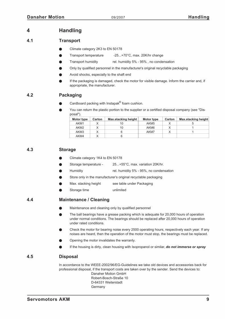
Motor type Carton Max.stacking height Motor type Carton Max.stacking height
AKM1 X 10 AKM5 X 5
AKM2 X 10 AKM6 X 1
AKM3 X 6 AKM7 X 1
AKM4 X 6
4.3 Storage
� Climate category 1K4 to EN 50178
� Storage temperature - 25...+55°C, max. variation 20K/hr.
� Humidity rel. humidity 5% - 95%, no condensation
� Store only in the manufacturer’s original recyclable packaging
� Max. stacking height see table under Packaging
� Storage time unlimited
4.4 Maintenance / Cleaning
� Maintenance and cleaning only by qualified personnel
� The ball bearings have a grease packing which is adequate for 20,000 hours of operation
under normal conditions. The bearings should be replaced after 20,000 hours of operation
under rated conditions.
� Check the motor for bearing noise every 2500 operating hours, respectively each year. If any
noises are heard, then the operation of the motor must stop, the bearings must be replaced.
� Opening the motor invalidates the warranty.
� If the housing is dirty, clean housing with Isopropanol or similar, do not immerse or spray
4.5 Disposal
In accordance to the WEEE-2002/96/EG-Guidelines we take old devices and accessories back for
professional disposal, if the transport costs are taken over by the sender. Send the devices to:
Danaher Motion GmbH
Robert-Bosch-Straße 10
D-64331 Weiterstadt
Germany
Servomotors AKM 9
Danaher Motion 09/2007 Handling
5 Package
5.1 Delivery package
� Motor from the AKM series
� Technical description on CDROM
� Motor package leaflet (short info)
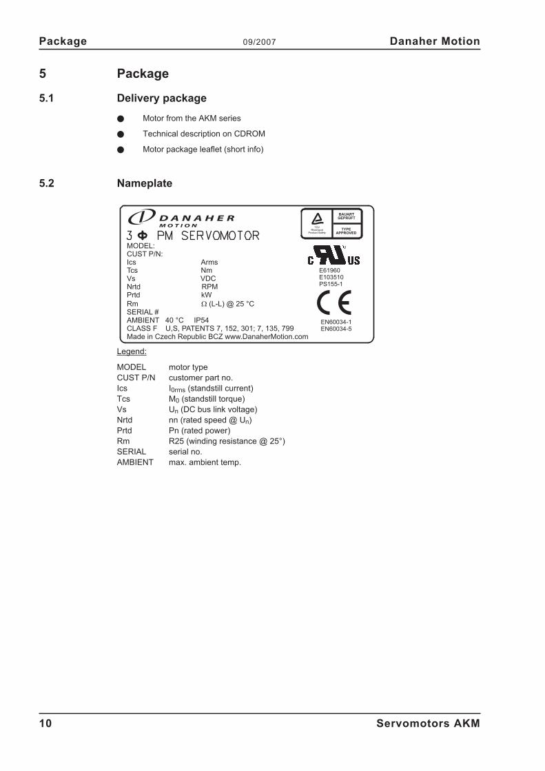
5.2 Nameplate
Legend:
MODEL motor type
CUST P/N customer part no.
Ics I0rms (standstill current)
Tcs M0 (standstill torque)
Vs Un (DC bus link voltage)
Nrtd nn (rated speed @ Un)
Prtd Pn (rated power)
Rm R25 (winding resistance @ 25°)
SERIAL serial no.
AMBIENT max. ambient temp.
10 Servomotors AKM
Package 09/2007 Danaher Motion
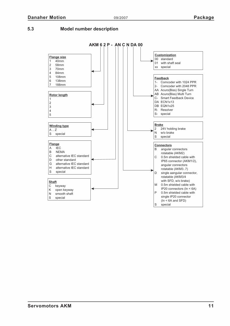
5.3 Model number description
Servomotors AKM 11
Danaher Motion 09/2007 Package
Flange size
1 40mm
2 58mm
3 70mm
4 84mm
5 108mm
6 138mm
7 188mm
Flange
A IEC
B NEMA
C alternative IEC standard
D other standard
G alternative IEC standard
H alternative IEC standard
S special
Rotor length
1
2
3
4
5
Winding type
A .. Z
S special
Connectors
B angular connectors
rotatable (AKM2)
C 0.5m shielded cable with
IP65 connector (AKM1/2),
angular connectors
rotatable (AKM3..7)
D single aangular connector,
rotatable (AKM3/4
with SFD, w/o brake)
M 0.5m shielded cable with
IP20 connectors (In < 6A)
P 0.5m shielded cable with
single IP20 connector
(In < 6A and SFD)
S special
Brake
2 24V holding brake
N w/o brake
S special
Feedback
1- Comcoder with 1024 PPR
2- Comcoder with 2048 PPR
AA Acuro(Biss) Single Turn
AB Acuro(Biss) Multi Turn
C- Smart Feedback Device
DA ECN1x13
DB EQN1x25
R- Resolver
S- special
Customization
00 standard
01 with shaft seal
xx special
Shaft
C keyway
K open keyway
N smooth shaft
S special
AKM 6 2 P - AN C N DA 00
6 Technical Description
6.1 Design of the motors
Synchronous servomotors in the AKM series are brushless DC motors for demanding servo appli-
cations. When combined with our digital servo amplifiers they are especially suited for positioning
tasks in industrial robots, machine tools, transfer lines etc. With high requirements for dynamics and
stability.
The servomotors have permanent magnets in the rotor. The rare earth neodymium -iron-boron
magnetic material is an important factor in making it possible to drive these motors in a highly dyna-
mic fashion. A three-phase winding which is driven by the servo amplifier is integrated into the sta-
tor. The motor does not have any brushes since commutation is performed electronically by the
servo amplifier
The temperature of the winding is monitored by temperature sensors in the stator windings and is
signalled via an electrically isolated thermistor (PTC, �550� / �1330�).
A resolver is built into the motors as standard feedback element. The servo amplifiers evaluate the
resolver position and supply sinusoidal currents to the motors.
The alternatively offered feedback systems partly cause a change of the motor length and cannot
be retrofitted.
The motors can be delivered with or without a built-in holding brake. Retrofitting of the brake is not
possible.
The motors are enamelled in matt black (RAL 9005). This finish is not resistant against solvents
(e.g. trichlorethylene, nitro-thinners, or similar).
6.2 General technical data
Climate category 3K3 to EN 50178
Ambient temperature 5...+40°C for site altitude up to 1000m amsl
(at rated values) It is vital to consult our applications department for
ambient temperatures above 40°C and encapsulated
mounting of the motors.
Permissible humidity 95% rel. humidity, no condensation
(at rated values)
Power derating 1% / K in range 40°C...50°C up to 1000m amsl
(currents and torques) for site altitude above 1000m amsl and 40°C
6% up to 2000m amsl
17% up to 3000m amsl
30% up to 4000m amsl
55% up to 5000m amsl
No derating for site altitudes above 1000m amsl
with temperature reduction of 10K / 1000m
Ball-bearing life � 20.000 operating hours
Technical data � p.27
Storage data � p.9
12 Servomotors AKM
Technical Description 09/2007 Danaher Motion
6.3 Standard features
6.3.1 Style
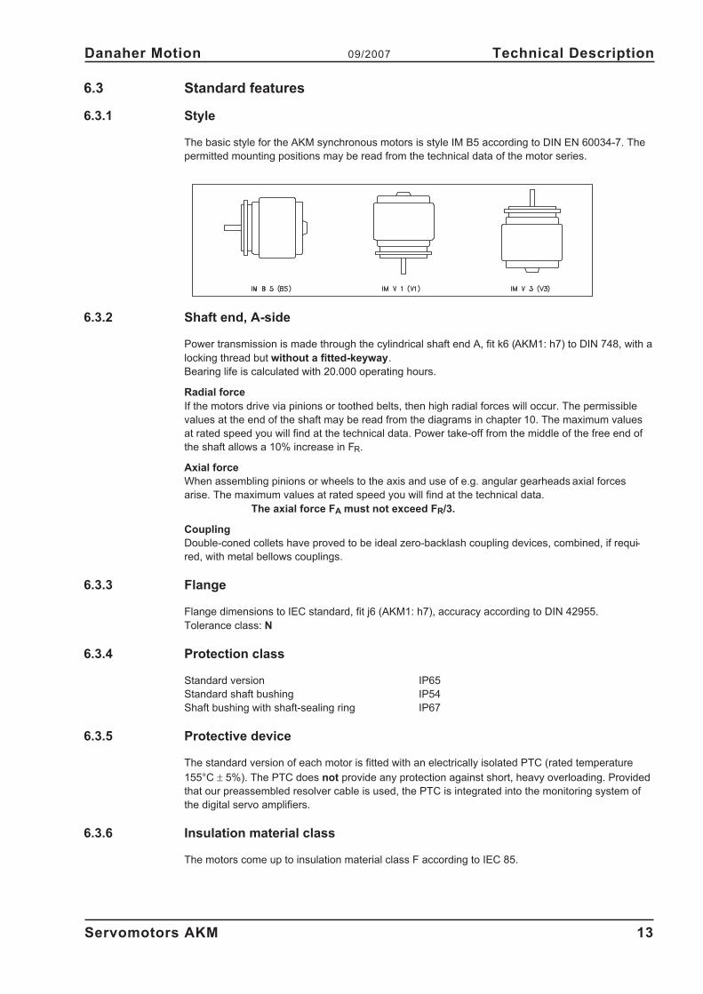
The basic style for the AKM synchronous motors is style IM B5 according to DIN EN 60034-7. The
permitted mounting positions may be read from the technical data of the motor series.
6.3.2 Shaft end, A-side
Power transmission is made through the cylindrical shaft end A, fit k6 (AKM1: h7) to DIN 748, with a
locking thread but without a fitted-keyway.
Bearing life is calculated with 20.000 operating hours.
Radial force
If the motors drive via pinions or toothed belts, then high radial forces will occur. The permissible
values at the end of the shaft may be read from the diagrams in chapter 10. The maximum values
at rated speed you will find at the technical data. Power take-off from the middle of the free end of
the shaft allows a 10% increase in FR.
Axial force
When assembling pinions or wheels to the axis and use of e.g. angular gearheads axial forces
arise. The maximum values at rated speed you will find at the technical data.
The axial force FA must not exceed FR/3.
Coupling
Double-coned collets have proved to be ideal zero-backlash coupling devices, combined, if requi-
red, with metal bellows couplings.
6.3.3 Flange
Flange dimensions to IEC standard, fit j6 (AKM1: h7), accuracy according to DIN 42955.
Tolerance class: N
6.3.4 Protection class
Standard version IP65
Standard shaft bushing IP54
Shaft bushing with shaft-sealing ring IP67
6.3.5 Protective device
The standard version of each motor is fitted with an electrically isolated PTC (rated temperature
155°C � 5%). The PTC does not provide any protection against short, heavy overloading. Provided
that our preassembled resolver cable is used, the PTC is integrated into the monitoring system of
the digital servo amplifiers.
6.3.6 Insulation material class
The motors come up to insulation material class F according to IEC 85.
Servomotors AKM 13
Danaher Motion 09/2007 Technical Description
6.3.7 Vibration class
The motors are made to vibration class N according to DIN EN 60034-14.
6.3.8 Connection method
The motors are equipped with angular connectors (AKM1: straight connectors at cable ends) for
power supply and feedback signals .
The mating connectors are not part of the delivery package. We can supply preassembled resolver
and power cables. On page 18 you will find notes on the cable materials.
6.3.9 Feedback unit
Standard Resolver Two-pole hollow-shaft
Option EnDat Encoder, Single-Turn AKM2-AKM4: ECN 1113, AKM5-AKM7: ECN1313
Option EnDat Encoder, Multi-Turn AKM2-AKM4: EQN 1125, AKM5-AKM7: EQN1325
Option ComCoderIncremental encoder with commutation,
resolution 500-10000 lines
Option SFD fully digital resolver interface
Option BiSS Encoder, Single-/Multi-Turn AKM2-AKM4: AD36, AKM5-AKM7: AD58
The motor length depends on the mounted feedback unit. Retrofitting is not possible.
6.3.10 Holding brake
The AKM2-AKM7 motors are optionally available with a holding brake.
A spring applied brake (24V DC) is integrated into the motors. When this brake is de-energized it
blocks the rotor. The holding brakes are designed as standstill brakes and are not suited for
repeated operational braking. If the brake is released then the rotor can be moved without a rema-
nent torque. The motor length increases when a holding brake is mounted.
The holding brake can be controlled directly by the servo amplifier (no personal safety !), the win-
ding is suppressed in the servo amplifier — additional circuitry is not required.
If the holding brake is not controlled directly by the servo amplifier, an additional wiring (e.g. varis-
tor) is required. Consult our applications department beforehand.
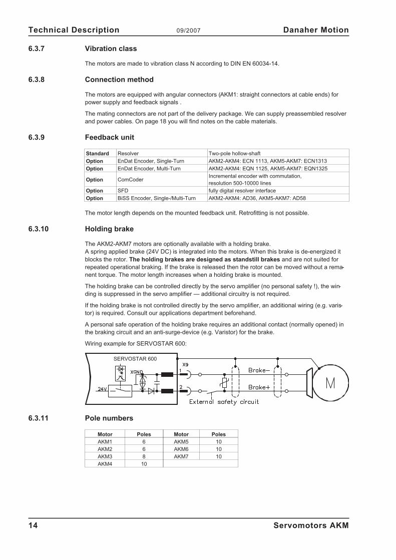
A personal safe operation of the holding brake requires an additional contact (normally opened) in
the braking circuit and an anti-surge-device (e.g. Varistor) for the brake.
Wiring example for SERVOSTAR 600:
6.3.11 Pole numbers
Motor Poles Motor Poles
AKM1 6 AKM5 10
AKM2 6 AKM6 10
AKM3 8 AKM7 10
AKM4 10
14 Servomotors AKM
Technical Description 09/2007 Danaher Motion
SERVOSTAR 600
6.4 Options
— Holding brake
Built-in holding brake.
Motor length increases by the holding brake.
— Radial shaft-sealing rings
A radial shaft-sealing ring can be supplied at extra charge to seal against oil mist
and oil spray. This increases the protection rating of the shaft bushing to IP67.
— Keyway
The motors are available with keyway and key inserted according to DIN6885
The shaft is balanced with a short (half) key.
— EnDat, BISS, ComCoder, SFD
Another feedback system is mounted instead of the resolver. The motor length
can increase by the alternative feedback.
With exception of the radial shaft seal the options cannot be retrofitted. Options such as radial shaft
seal, holding brake, EnDat or Comcoder can lead to a reduction of rated data.
6.5 Selection criteria
The three-phase servomotors are designed to operate with SERVOSTAR servo amplifiers. Toget-
her, both units form a closed speed or torque control loop.
The most important selection criteria are:
— Standstill torque M0 [Nm]
— Rated speed nn [min-1
]
— Moment of inertia of motor and load J [kgcm²]
— Effective torque (calculated) Mrms [Nm]
When calculating the motors and servo amplifiers which are required, take account of the static load
and the dynamic load (acceleration/braking). Collected formulae and examples of the calculations
are available from our applications department.
Servomotors AKM 15
Danaher Motion 09/2007 Technical Description
7 Mechanical Installation
7.1 Important Notes
Only qualified staff with knowledge of mechanical engineering are permitted to assemble
the motor.
� Protect the motor from unacceptable stresses.
Take care, especially during transport and handling, that components are not bent and that
insulation clearances are not altered.
� The site must be free of conductive and aggressive material. For V3-mounting (shaft end up-
wards), make sure that no liquids can enter the bearings. If an encapsulated assembly is re-
quired, please consult our applications department beforehand.
� Ensure an unhindered ventilation of the motors and observe the permissible ambient and
flange temperatures. For ambient temperatures above 40°C please consult our applications
department beforehand.
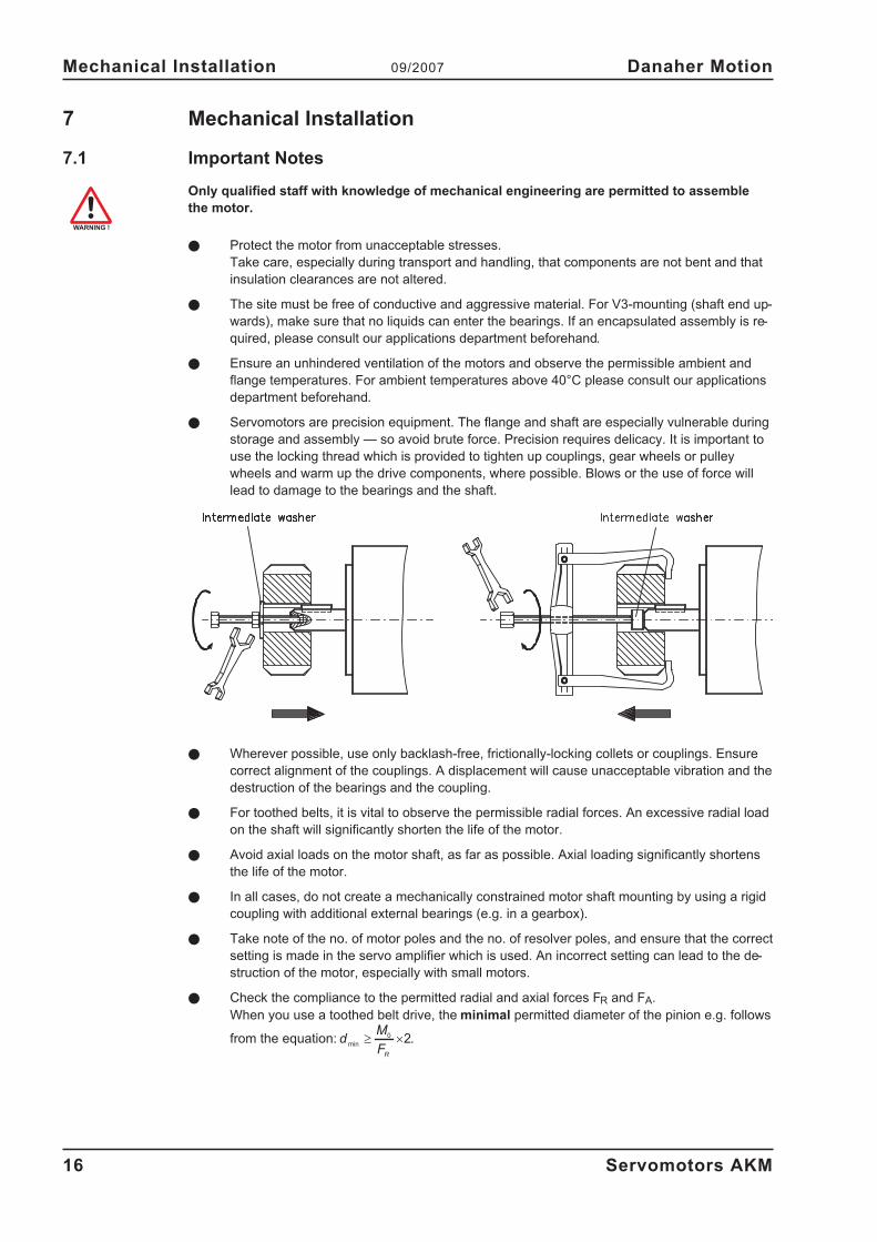
� Servomotors are precision equipment. The flange and shaft are especially vulnerable during
storage and assembly — so avoid brute force. Precision requires delicacy. It is important to
use the locking thread which is provided to tighten up couplings, gear wheels or pulley
wheels and warm up the drive components, where possible. Blows or the use of force will
lead to damage to the bearings and the shaft.
� Wherever possible, use only backlash-free, frictionally-locking collets or couplings. Ensure
correct alignment of the couplings. A displacement will cause unacceptable vibration and the
destruction of the bearings and the coupling.
� For toothed belts, it is vital to observe the permissible radial forces. An excessive radial load
on the shaft will significantly shorten the life of the motor.
� Avoid axial loads on the motor shaft, as far as possible. Axial loading significantly shortens
the life of the motor.
� In all cases, do not create a mechanically constrained motor shaft mounting by using a rigid
coupling with additional external bearings (e.g. in a gearbox).
� Take note of the no. of motor poles and the no. of resolver poles, and ensure that the correct
setting is made in the servo amplifier which is used. An incorrect setting can lead to the de-
struction of the motor, especially with small motors.
� Check the compliance to the permitted radial and axial forces FR and FA.
When you use a toothed belt drive, the minimal permitted diameter of the pinion e.g. follows
from the equation: dM
FR
min� �
0 2.
16 Servomotors AKM
Mechanical Installation 09/2007 Danaher Motion
8 Electrical Installation
8.1 Safety notes
Only staff qualified and trained in electrical engineering are allowed to wire up the motor.
Always make sure that the motors are de-energized during assembly and wiring, i.e. No vol-
tage may be switched on for any piece of equipment which is to be connected.
Ensure that the switch cabinet remains turned off (barrier, warning signs etc.).
The individual voltages will only be turned on again during setup.
Never undo the electrical connections to the motor while it is energised. A dangerous volta-
ge, resulting from residual charge, can be still present on the capacitors up to 5 minutes af-
ter switch-off of the mains supply.
Measure the DC-link voltage and wait until it has fallen below 40V.
Even when the motor is not rotating, control and power leads may be live.
The ground symbol�, which you will find in the wiring diagrams, indicates that you
must provide an electrical connection, with as large a surface area as possible, between the
unit indicated and the mounting plate in the switch cabinet. This connection is to suppress
HF interference and must not be confused with the PE (protective earth) symbol (protective
measure to EN 60204).
To wire up the motor, use the wiring diagrams in the Installation and Setup Instructions of
the servo amplifier which is used.
Servomotors AKM 17
Danaher Motion 09/2007 Electrical Installation
8.2 Guide for electrical installation
� Check that the servo amplifier and motor match each other. Compare the rated voltage and
rated current of the unit. Carry out the wiring according to the wiring diagram in the product
manual of the servo amplifier. The connections to the motor are shown on pages 19f. Notes
on the connection methods can be found on page 18.
� Ensure that there is proper earthing of the servo amplifier and the motor. Use correct eart-
hing and EMC-shielding according to the product manual of the servo amplifier which is
used. Earth the mounting plate and motor casing. For connection methods see chapter 8.3.
� Route the power and control cables as separately as possible from one another (separation
> 20 cm). This will improve the immunity of the system to electromagnetic interference.
If a motor power cable is used which includes integral brake control leads, then these brake
control leads must be shielded. The shielding must be connected at both ends (see product
manual of the servo amplifier).
� Cabling:
— Route power cables as separately as possible from control cables
— Connect up the resolver or encoder.
— Connect the motor cables, install motor chokes close to the servo amplifier
— Connect shields to shielding terminals or EMC connectors at both ends
— Connect the holding brake, if used
— Connect shielding at both ends.
� Install all cables carrying a heavy current with an adequate cross-section, as per EN 60204.
The recommended cross-section can be found in the Technical data.
In case of long motor cables (>25m) and dependent on the type of the used servo am-
plifier a motor choke (3YL) must be switched into the motor cable (see product manu-
al of the servo amplifier and accessory manual).
� Connect up all shielding via a wide surface-area contact (low impedance) and metallized
connector housings or EMC-cable glands.
8.3 Connection of the motors with preassembled cables
� Carry out the wiring in accordance with the valid standards and regulations.
� Only use our preassembled shielded cables for the resolver and power connections.
� Connect up the shielding according to the wiring diagrams in the product manual for
the servo amplifier.
� Incorrectly installed shielding inevitably cables to EMC interference.
� The maximum cable length is defined in the product manual of the used servo ampli-
fier.
Requirements to cable material:
Capacity
Motor cable less than 150 pF/m
Resolver cable less than 120 pF/m
For a detailed description of preassembled cables, please refer to the accessories manual.
18 Servomotors AKM
Electrical Installation 09/2007 Danaher Motion
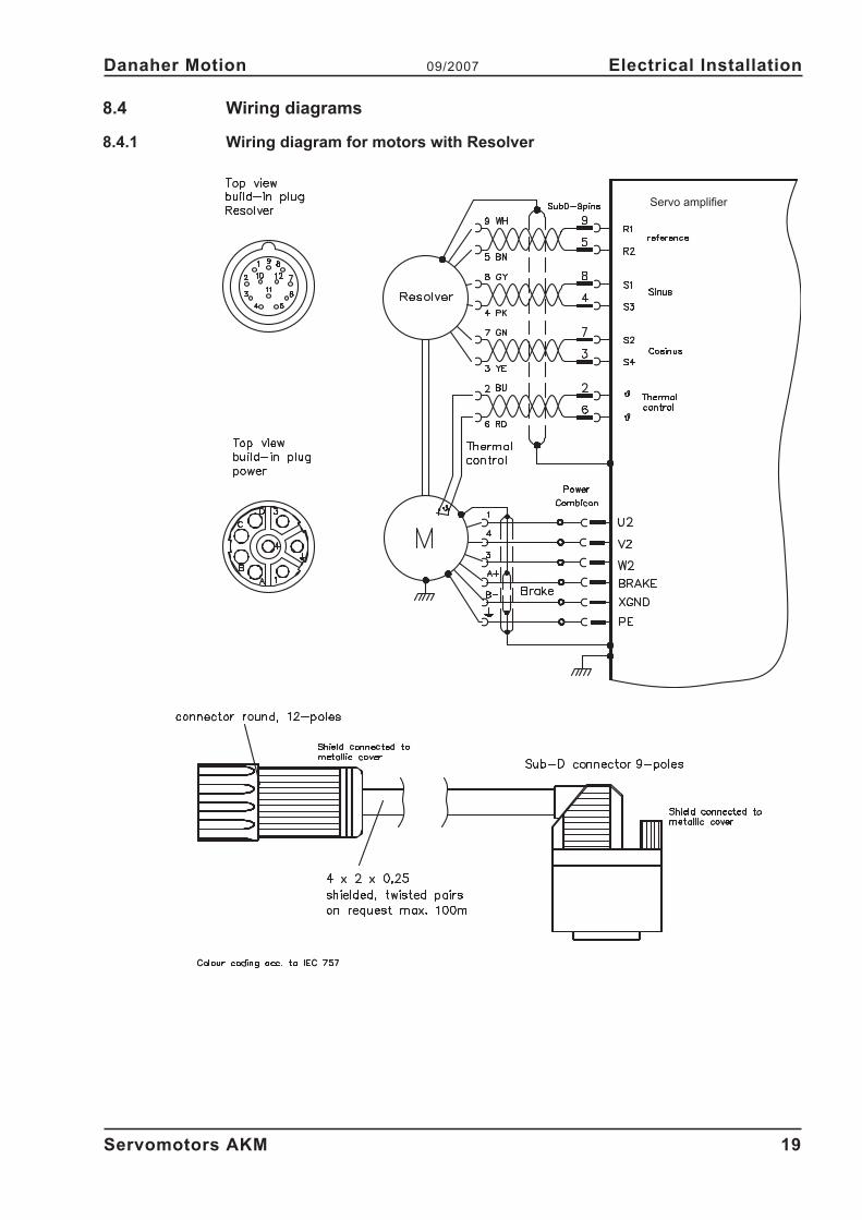
8.4 Wiring diagrams
8.4.1 Wiring diagram for motors with Resolver
Servomotors AKM 19
Danaher Motion 09/2007 Electrical Installation
Servo amplifier
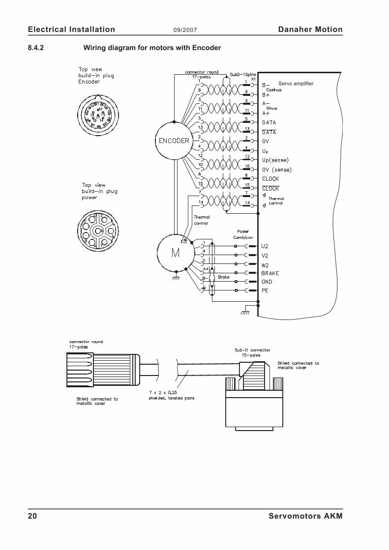
8.4.2 Wiring diagram for motors with Encoder
20 Servomotors AKM
Electrical Installation 09/2007 Danaher Motion
Servo amplifier
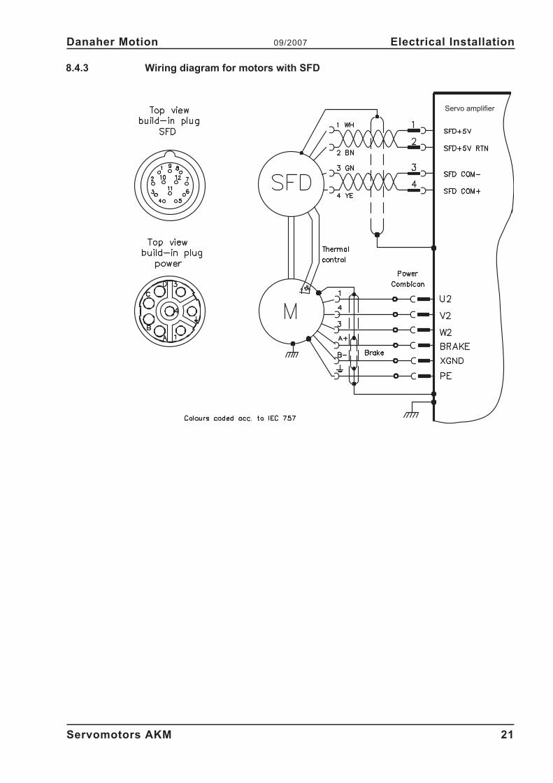
8.4.3 Wiring diagram for motors with SFD
Servomotors AKM 21
Danaher Motion 09/2007 Electrical Installation
Servo amplifier
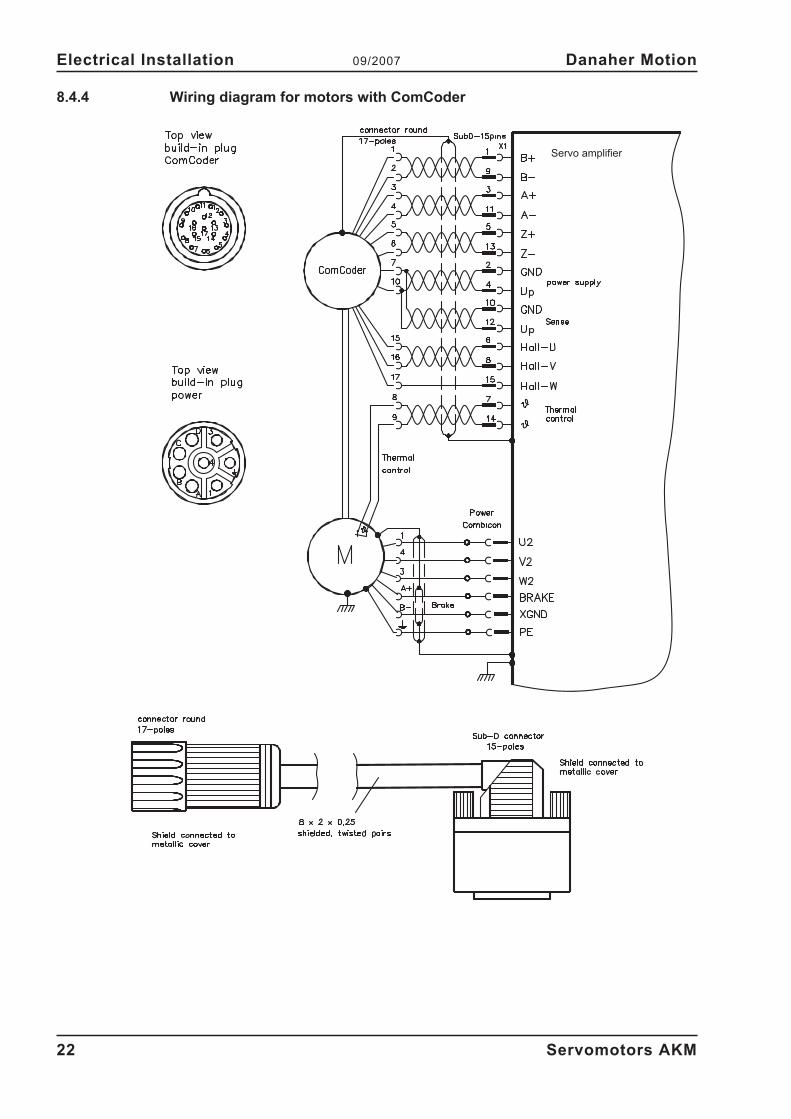
8.4.4 Wiring diagram for motors with ComCoder
22 Servomotors AKM
Electrical Installation 09/2007 Danaher Motion
Servo amplifier
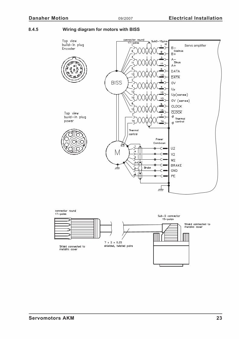
8.4.5 Wiring diagram for motors with BISS
Servomotors AKM 23
Danaher Motion 09/2007 Electrical Installation
Servo amplifier

This page has been deliberately left blank.
24 Servomotors AKM
Electrical Installation 09/2007 Danaher Motion
9 Setup
9.1 Important notes
Only specialist personnel with extensive knowledge in the areas of electrical engineering /
drive technology are allowed to commission the drive unit of servo amplifier and motor.
Check that all live connection points (terminal boxes) are safe against accidental contact.
Deadly voltages can occur, up to 900V.
Never undo the electrical connections to the motor when it is live. The residual charge in the
capacitors of the servo amplifier can produce dangerous voltages up to 5 minutes after the
mains supply has been switched off.
The surface temperature of the motor can exceed 100°C in operation. Check (measure) the
temperature of the motor. Wait until the motor has cooled down below 40°C before touching
it.
Make sure that, even if the drive starts to move unintentionally, no danger can result for per-
sonnel or machinery.
9.2 Guide for setup
The procedure for setup is described as an example. A different method may be appropriate or
necessary, depending on the application of the equipment.
� Check the assembly and orientation of the motor.
� Check the drive components (clutch, gear unit, belt pulley) for the correct seating and setting
(observe the permissible radial and axial forces).
� Check the wiring and connections to the motor and the servo amplifier. Check that the eart-
hing is correct.
� Test the function of the holding brake, if used. (apply 24V, the brake must be released).
� Check whether the rotor of the motor revolves freely (release the brake, if necessary). Listen
out for grinding noises.
� Check that all the required measures against accidental contact with live and moving parts
have been carried out.
� Carry out any further tests which are specifically required for your system.
� Now commission the drive according to the setup instructions for the servo amplifier.
� In multi-axis systems, individually commission each drive unit (servo amplifier and motor).
Servomotors AKM 25
Danaher Motion 09/2007 Setup
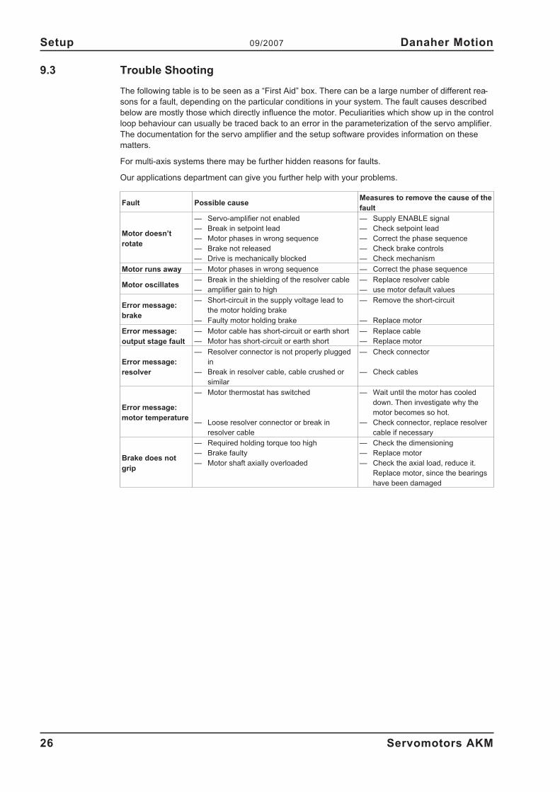
9.3 Trouble Shooting
The following table is to be seen as a “First Aid” box. There can be a large number of different rea-
sons for a fault, depending on the particular conditions in your system. The fault causes described
below are mostly those which directly influence the motor. Peculiarities which show up in the control
loop behaviour can usually be traced back to an error in the parameterization of the servo amplifier.
The documentation for the servo amplifier and the setup software provides information on these
matters.
For multi-axis systems there may be further hidden reasons for faults.
Our applications department can give you further help with your problems.
Fault Possible causeMeasures to remove the cause of the
fault
Motor doesn’t
rotate
— Servo-amplifier not enabled
— Break in setpoint lead
— Motor phases in wrong sequence
— Brake not released
— Drive is mechanically blocked
— Supply ENABLE signal
— Check setpoint lead
— Correct the phase sequence
— Check brake controls
— Check mechanism
Motor runs away — Motor phases in wrong sequence — Correct the phase sequence
Motor oscillates— Break in the shielding of the resolver cable
— amplifier gain to high
— Replace resolver cable
— use motor default values
Error message:
brake
— Short-circuit in the supply voltage lead to
the motor holding brake
— Faulty motor holding brake
— Remove the short-circuit
— Replace motor
Error message:
output stage fault
— Motor cable has short-circuit or earth short
— Motor has short-circuit or earth short
— Replace cable
— Replace motor
Error message:
resolver
— Resolver connector is not properly plugged
in
— Break in resolver cable, cable crushed or
similar
— Check connector
— Check cables
Error message:
motor temperature
— Motor thermostat has switched
— Loose resolver connector or break in
resolver cable
— Wait until the motor has cooled
down. Then investigate why the
motor becomes so hot.
— Check connector, replace resolver
cable if necessary
Brake does not
grip
— Required holding torque too high
— Brake faulty
— Motor shaft axially overloaded
— Check the dimensioning
— Replace motor
— Check the axial load, reduce it.
Replace motor, since the bearings
have been damaged
26 Servomotors AKM
Setup 09/2007 Danaher Motion
10 Technical Data
All data valid for 40°C environmental temperature and 100K overtemperature of the winding. The
data can have a tolerance of +/- 10%.
10.1 Definition of Terms
Standstill torque M0 [Nm]
The standstill torque can be maintained indefinitely at a speed n<100 min-1
and rated ambient con-
ditions.
Rated torque Mn [Nm]
The rated torque is produced when the motor is drawing the rated current at the rated speed. The
rated torque can be produced indefinitely at the rated speed in continuous operation (S1).
Standstill current I0rms [A]
The standstill current is the effective sinusoidal current which the motor draws at n<100 min-1
to
produce the standstill torque.
Peak current (pulse current) I0max [A]
The peak current (effective sinusoidal value) is approximately equivalent to 4-times the rated cur-
rent. The actual value is determined by the peak current of the servo amplifier which is used.
Torque constant KTrms [Nm/A]
The torque constant defines how much torque in Nm is produced by the motor with 1A r.m.s. cur-
rent. The relationship is M=I x KT (up to I = 2 x I0)
Voltage constant KErms [mV/min-1
]
The voltage constant defines the induced motor EMF, as an effective sinusoidal value between two
terminals, per 1000 rpm
Rotor moment of inertia J [kgcm²]
The constant J is a measure of the acceleration capability of the motor. For instance, at I0 the acce-
leration time tb from 0 to 3000 rpm is given as:
t sM s
m
cmJ
b[ ] �
�
��
��
3000 2
60 100
2
4 2
with M0 in Nm and J in kgcm²
Thermal time constant tth [min]
The constant tth defines the time for the cold motor, under a load of I0, to heat up to an overtempe-
rature of 0.63 x 10⁵ Kelvin. This temperature rise happens in a much shorter time when the motor is
loaded with the rated current.
Release delay time tBRH [ms] / Application delay time tBRL [ms] of the brake
These constants define the response times of the holding brake when operated with the rated vol-
tage from the servo amplifier.
UN
Rated mains voltage
Un
DC-Bus link voltage. U Un N
� 2
Servomotors AKM 27
Danaher Motion 09/2007 Technical Data
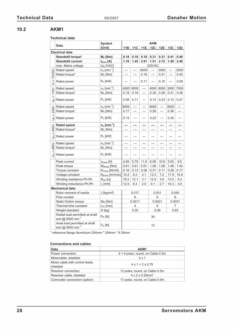
10.2 AKM1
Technical data
DataSymbol
[Unit]
AKM
11B 11C 11E 12C 12E 13C 13D
Electrical data
Standstill torque* M0 [Nm] 0.18 0.18 0.18 0.31 0.31 0.41 0.40
Standstill current I0rms [A] 1.16 1.45 2.91 1.51 2.72 1.48 2.40
max. Mains voltage UN [VAC] 230VAC
U=
75
VD
C Rated speed nn [min-1
] — — 6000 — 3000 — 2000
Rated torque* Mn [Nm] — — 0.18 — 0.31 — 0.40
Rated power Pn [kW] — — 0.11 — 0.10 — 0.08
UN
=1
15
V Rated speed nn [min-1
] 4000 6000 — 4000 8000 3000 7000
Rated torque* Mn [Nm] 0.18 0.18 — 0.30 0.28 0.41 0.36
Rated power Pn [kW] 0.08 0.11 — 0.13 0.23 0.13 0.27
UN
=2
30
V Rated speed nn [min-1
] 8000 — — 8000 — 8000 —
Rated torque* Mn [Nm] 0.17 — — 0.28 — 0.36 —
Rated power Pn [kW] 0.14 — — 0.23 — 0.30 —
UN
=4
00
V Rated speed nn [min-1
] — — — — — — —
Rated torque* Mn [Nm] — — — — — — —
Rated power Pn [kW] — — — — — — —
UN
=4
80
V Rated speed nn [min-1
] — — — — — — —
Rated torque* Mn [Nm] — — — — — — —
Rated power Pn [kW] — — — — — — —
Peak current I0max [A] 4.65 5.79 11.6 6.06 10.9 5.93 9.6
Peak torque M0max [Nm] 0.61 0.61 0.61 1.08 1.08 1.46 1.44
Torque constant KTrms [Nm/A] 0.16 0.13 0.06 0.21 0.11 0.28 0.17
Voltage constant KErms [mVmin] 10.2 8.3 4.1 13.3 7.2 17.9 10.9
Winding resistance Ph-Ph R25 [�] 18.2 12.1 3.1 12.4 3.9 13.5 5.4
Winding inductance Ph-Ph L [mH] 12.5 8.3 2.0 9.1 2.7 10.3 3.8
Mechanical data
Rotor moment of inertia J [kgcm²] 0.017 0.031 0.045
Pole number 6 6 6
Static friction torque MR [Nm] 0.0011 0.0021 0.0031
Thermal time constant tTH [min] 4 6 7
Weight standard G [kg] 0.35 0.49 0.63
Radial load permitted at shaft
end @ 8000 min-1 FR [N] 30
Axial load permitted at shaft
end @ 8000 min-1 FA [N] 12
* reference flange Aluminium 254mm * 254mm * 6.35mm
Connections and cables
Data AKM1
Power connection 4 + 4 poles, round, on Cable 0.5m
Motorcable, shielded 4 x 1
Motor cable with control leads,
shielded4 x 1 + 2 x 0.75
Resolver connection 12 poles, round, on Cable 0.5m
Resolver cable, shielded 4 x 2 x 0.25mm²
Comcoder connection (option) 17 poles, round, on Cable 0.5m
28 Servomotors AKM
Technical Data 09/2007 Danaher Motion
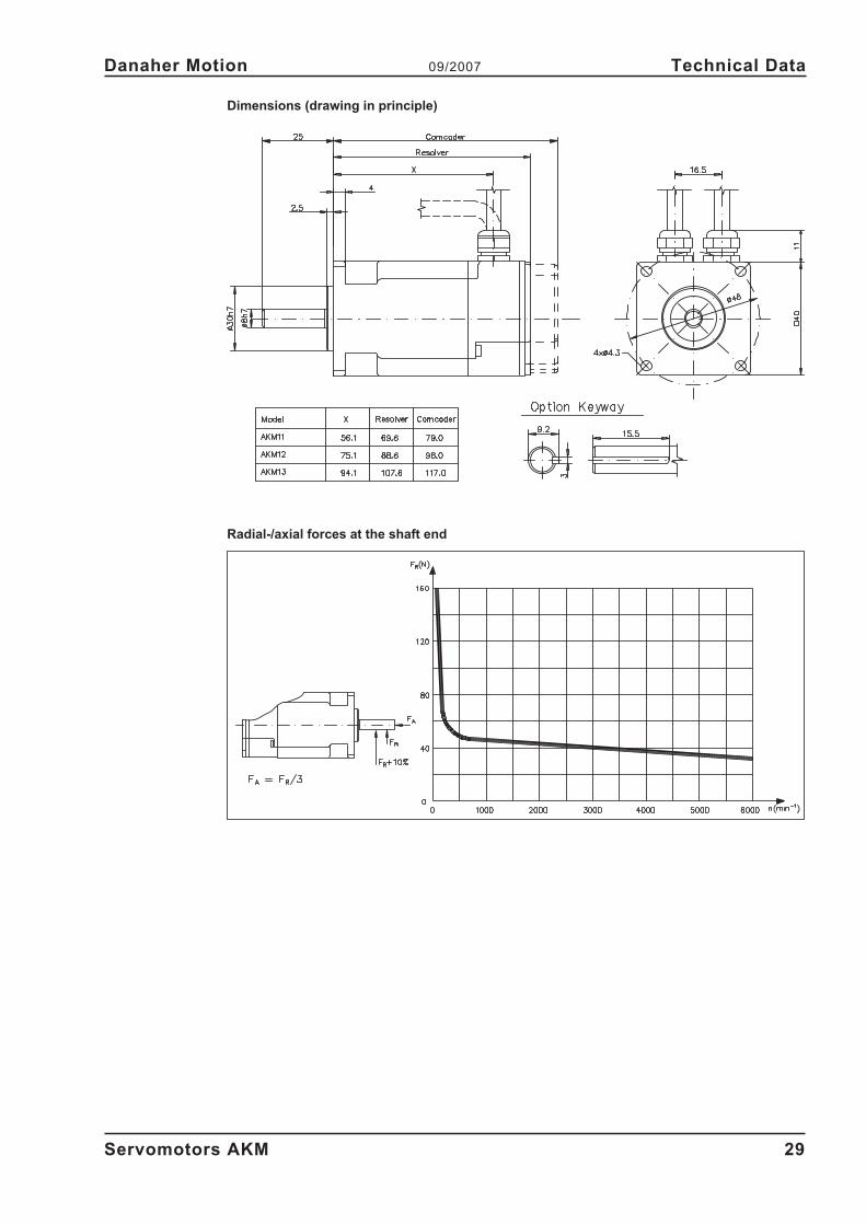
Dimensions (drawing in principle)
Radial-/axial forces at the shaft end
Servomotors AKM 29
Danaher Motion 09/2007 Technical Data
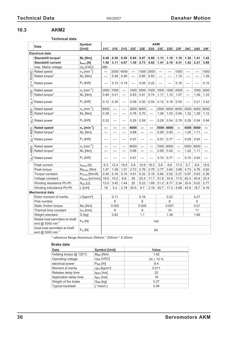
10.3 AKM2
Technical data
DataSymbol
[Unit]
AKM
21C 21E 21G 22C 22E 22G 23C 23D 23F 24C 24D 24F
Electrical data
Standstill torque* M0 [Nm] 0.48 0.50 0.50 0.84 0.87 0.88 1.13 1.16 1.18 1.38 1.41 1.42
Standstill current I0rms [A] 1.58 3.11 4.87 1.39 2.73 4.82 1.41 2.19 4.31 1.42 2.21 3.89
max. Mains voltage UN [VAC] 480
U=
75
VD
C Rated speed nn [min-1
] — 2000 4000 — 1000 2500 — — 1500 — — 1000
Rated torque* Mn [Nm] — 0.48 0.46 — 0.85 0.83 — — 1.15 — — 1.39
Rated power Pn [kW] — 0.10 0.19 — 0.09 0.22 — — 0.18 — — 0.15
UN
=1
15
V Rated speed nn [min-1
] 2500 7000 — 1000 3500 7000 1000 1500 4500 — 1500 3000
Rated torque* Mn [Nm] 0.46 0.41 — 0.83 0.81 0.74 1.11 1.12 1.07 — 1.36 1.33
Rated power Pn [kW] 0.12 0.30 — 0.09 0.30 0.54 0.12 0.18 0.50 — 0.21 0.42
UN
=2
30
V Rated speed nn [min-1
] 8000 — — 3500 8000 — 2500 5000 8000 2000 4000 8000
Rated torque* Mn [Nm] 0.39 — — 0.78 0.70 — 1.08 1.03 0.94 1.32 1.29 1.12
Rated power Pn [kW] 0.32 — — 0.29 0.59 — 0.28 0.54 0.79 0.28 0.54 0.94
UN
=4
00
V Rated speed nn [min-1
] — — — 8000 — — 5500 8000 — 4500 8000 —
Rated torque* Mn [Nm] — — — 0.68 — — 0.99 0.92 — 1.25 1.11 —
Rated power Pn [kW] — — — 0.57 — — 0.57 0.77 — 0.59 0.93 —
UN
=4
80
V Rated speed nn [min-1
] — — — 8000 — — 7000 8000 — 5500 8000 —
Rated torque* Mn [Nm] — — — 0.68 — — 0.95 0.92 — 1.22 1.11 —
Rated power Pn [kW] — — — 0.57 — — 0.70 0.77 — 0.70 0.93 —
Peak current I0max [A] 6.3 12.4 19.5 5.6 10.9 19.3 5.6 8.8 17.2 5.7 8.8 15.6
Peak torque M0max [Nm] 1.47 1.49 1.51 2.73 2.76 2.79 3.77 3.84 3.88 4.73 4.76 4.82
Torque constant KTrms [Nm/A] 0.30 0.16 0.10 0.61 0.32 0.18 0.80 0.52 0.27 0.97 0.63 0.36
Voltage constant KErms [mVmin] 19.5 10.2 6.6 39 20.4 11.7 51.8 33.8 17.6 62.4 40.8 23.4
Winding resistance Ph-Ph R25 [�] 13.0 3.42 1.44 20 5.22 1.69 21.2 8.77 2.34 20.4 9.02 2.77
Winding inductance Ph-Ph L [mH] 19 5.2 2.18 35.5 9.7 3.19 40.7 17.3 4.68 43.8 18.7 6.16
Mechanical data
Rotor moment of inertia J [kgcm²] 0.11 0.16 0.22 0.27
Pole number 6 6 6 6
Static friction torque MR [Nm] 0.002 0.005 0.007 0.01
Thermal time constant tTH [min] 8 9 10 11
Weight standard G [kg] 0.82 1.1 1.38 1.66
Radial load permitted at shaft
end @ 5000 min-1 FR [N] 145
Axial load permitted at shaft
end @ 5000 min-1 FA [N] 60
* reference flange Aluminium 254mm * 254mm * 6.35mm
Brake data
Data Symbol [Unit] Value
Holding torque @ 120°C MBR [Nm] 1.42
Operating voltage UBR [VDC] 24 � 10 %
electrical power PBR [W] 8.4
Moment of inertia JBR [kgcm²] 0.011
Release delay time tBRH [ms] 20
Application delay time tBRL [ms] 18
Weight of the brake GBR [kg] 0.27
Typical backlash [ °mech.] 0.46
30 Servomotors AKM
Technical Data 09/2007 Danaher Motion
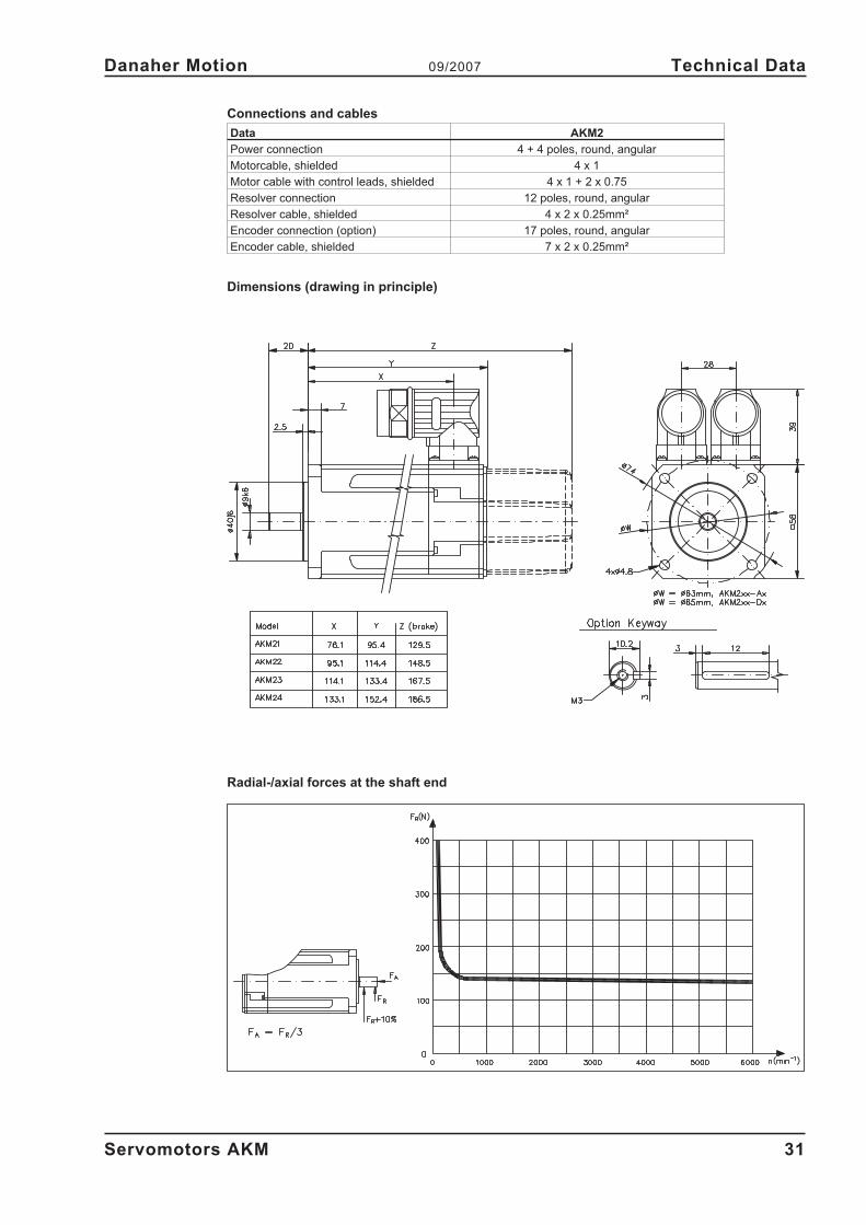
Connections and cables
Data AKM2
Power connection 4 + 4 poles, round, angular
Motorcable, shielded 4 x 1
Motor cable with control leads, shielded 4 x 1 + 2 x 0.75
Resolver connection 12 poles, round, angular
Resolver cable, shielded 4 x 2 x 0.25mm²
Encoder connection (option) 17 poles, round, angular
Encoder cable, shielded 7 x 2 x 0.25mm²
Dimensions (drawing in principle)
Radial-/axial forces at the shaft end
Servomotors AKM 31
Danaher Motion 09/2007 Technical Data
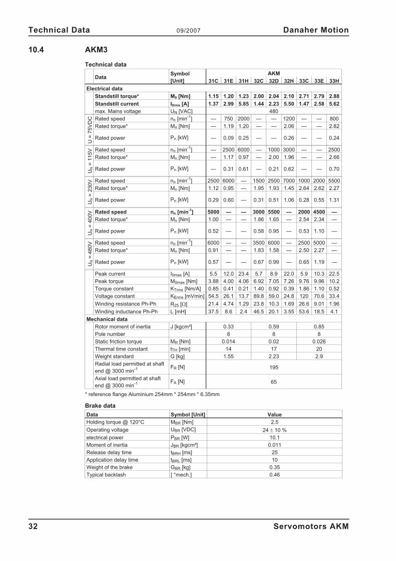
10.4 AKM3
Technical data
DataSymbol
[Unit]
AKM
31C 31E 31H 32C 32D 32H 33C 33E 33H
Electrical data
Standstill torque* M0 [Nm] 1.15 1.20 1.23 2.00 2.04 2.10 2.71 2.79 2.88
Standstill current I0rms [A] 1.37 2.99 5.85 1.44 2.23 5.50 1.47 2.58 5.62
max. Mains voltage UN [VAC] 480
U=
75
VD
C Rated speed nn [min-1
] — 750 2000 — — 1200 — — 800
Rated torque* Mn [Nm] — 1.19 1.20 — — 2.06 — — 2.82
Rated power Pn [kW] — 0.09 0.25 — — 0.26 — — 0.24
UN
=1
15
V Rated speed nn [min-1
] — 2500 6000 — 1000 3000 — — 2500
Rated torque* Mn [Nm] — 1.17 0.97 — 2.00 1.96 — — 2.66
Rated power Pn [kW] — 0.31 0.61 — 0.21 0.62 — — 0.70
UN
=2
30
V Rated speed nn [min-1
] 2500 6000 — 1500 2500 7000 1000 2000 5500
Rated torque* Mn [Nm] 1.12 0.95 — 1.95 1.93 1.45 2.64 2.62 2.27
Rated power Pn [kW] 0.29 0.60 — 0.31 0.51 1.06 0.28 0.55 1.31
UN
=4
00
V Rated speed nn [min-1
] 5000 — — 3000 5500 — 2000 4500 —
Rated torque* Mn [Nm] 1.00 — — 1.86 1.65 — 2.54 2.34 —
Rated power Pn [kW] 0.52 — — 0.58 0.95 — 0.53 1.10 —
UN
=4
80
V Rated speed nn [min-1
] 6000 — — 3500 6000 — 2500 5000 —
Rated torque* Mn [Nm] 0.91 — — 1.83 1.58 — 2.50 2.27 —
Rated power Pn [kW] 0.57 — — 0.67 0.99 — 0.65 1.19 —
Peak current I0max [A] 5.5 12.0 23.4 5.7 8.9 22.0 5.9 10.3 22.5
Peak torque M0max [Nm] 3.88 4.00 4.06 6.92 7.05 7.26 9.76 9.96 10.2
Torque constant KTrms [Nm/A] 0.85 0.41 0.21 1.40 0.92 0.39 1.86 1.10 0.52
Voltage constant KErms [mVmin] 54.5 26.1 13.7 89.8 59.0 24.8 120 70.6 33.4
Winding resistance Ph-Ph R25 [�] 21.4 4.74 1.29 23.8 10.3 1.69 26.6 9.01 1.96
Winding inductance Ph-Ph L [mH] 37.5 8.6 2.4 46.5 20.1 3.55 53.6 18.5 4.1
Mechanical data
Rotor moment of inertia J [kgcm²] 0.33 0.59 0.85
Pole number 8 8 8
Static friction torque MR [Nm] 0.014 0.02 0.026
Thermal time constant tTH [min] 14 17 20
Weight standard G [kg] 1.55 2.23 2.9
Radial load permitted at shaft
end @ 3000 min-1 FR [N] 195
Axial load permitted at shaft
end @ 3000 min-1 FA [N] 65
* reference flange Aluminium 254mm * 254mm * 6.35mm
Brake data
Data Symbol [Unit] Value
Holding torque @ 120°C MBR [Nm] 2.5
Operating voltage UBR [VDC] 24 � 10 %
electrical power PBR [W] 10.1
Moment of inertia JBR [kgcm²] 0.011
Release delay time tBRH [ms] 25
Application delay time tBRL [ms] 10
Weight of the brake GBR [kg] 0.35
Typical backlash [ °mech.] 0.46
32 Servomotors AKM
Technical Data 09/2007 Danaher Motion
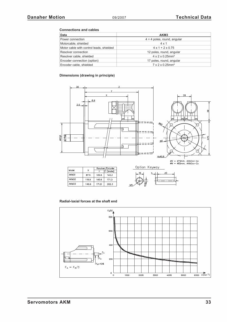
Connections and cables
Data AKM3
Power connection 4 + 4 poles, round, angular
Motorcable, shielded 4 x 1
Motor cable with control leads, shielded 4 x 1 + 2 x 0.75
Resolver connection 12 poles, round, angular
Resolver cable, shielded 4 x 2 x 0.25mm²
Encoder connection (option) 17 poles, round, angular
Encoder cable, shielded 7 x 2 x 0.25mm²
Dimensions (drawing in principle)
Radial-/axial forces at the shaft end
Servomotors AKM 33
Danaher Motion 09/2007 Technical Data
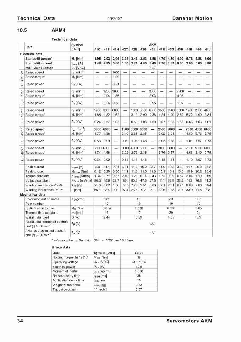
10.5 AKM4
Technical data
DataSymbol
[Unit]
AKM
41C 41E 41H 42C 42E 42G 42J 43E 43G 43K 44E 44G 44J
Electrical data
Standstill torque* M0 [Nm] 1.95 2.02 2.06 3.35 3.42 3.53 3.56 4.70 4.80 4.90 5.76 5.88 6.00
Standstill current I0rms [A] 1.46 2.85 5.60 1.40 2.74 4.80 8.40 2.76 4.87 9.60 2.90 5.00 8.80
max. Mains voltage UN [VAC] 480
U=
75
VD
C Rated speed nn [min-1
] — — 1000 — — — — — — — — — —
Rated torque* Mn [Nm] — — 1.99 — — — — — — — — — —
Rated power Pn [kW] — — 0.21 — — — — — — — — — —
UN
=1
15
V Rated speed nn [min-1
] — 1200 3000 — — — 3000 — — 2500 — — —
Rated torque* Mn [Nm] — 1.94 1.86 — — — 3.03 — — 4.08 — — —
Rated power Pn [kW] — 0.24 0.58 — — — 0.95 — — 1.07 — — —
UN
=2
30
V Rated speed nn [min-1
] 1200 3000 6000 — 1800 3500 6000 1500 2500 6000 1200 2000 4000
Rated torque* Mn [Nm] 1.88 1.82 1.62 — 3.12 2.90 2.38 4.24 4.00 2.62 5.22 4.90 3.84
Rated power Pn [kW] 0.24 0.57 1.02 — 0.59 1.06 1.50 0.67 1.05 1.65 0.66 1.03 1.61
UN
=4
00
V Rated speed nn [min-1
] 3000 6000 — 1500 3500 6000 — 2500 5000 — 2000 4000 6000
Rated torque* Mn [Nm] 1.77 1.58 — 3.10 2.81 2.35 — 3.92 3.01 — 4.80 3.76 2.75
Rated power Pn [kW] 0.56 0.99 — 0.49 1.03 1.48 — 1.03 1.58 — 1.01 1.57 1.73
UN
=4
80
V Rated speed nn [min-1
] 3500 6000 — 2000 4000 6000 — 3000 6000 — 2500 5000 6000
Rated torque* Mn [Nm] 1.74 1.58 — 3.02 2.72 2.35 — 3.76 2.57 — 4.56 3.19 2.75
Rated power Pn [kW] 0.64 0.99 — 0.63 1.14 1.48 — 1.18 1.61 — 1.19 1.67 1.73
Peak current I0max [A] 5.8 11.4 22.4 5.61 11.0 19.2 33.7 11.0 19.5 38.3 11.4 20.0 35.2
Peak torque M0max [Nm] 6.12 6.28 6.36 11.1 11.3 11.5 11.6 15.9 16.1 16.3 19.9 20.2 20.4
Torque constant KTrms [Nm/A] 1.34 0.71 0.37 2.40 1.26 0.74 0.43 1.72 0.99 0.52 2.04 1.19 0.69
Voltage constant KErms [mVmin] 86.3 45.6 23.7 154 80.9 47.5 27.5 111 63.9 33.2 132 76.6 44.2
Winding resistance Ph-Ph R25 [�] 21.3 6.02 1.56 27.5 7.78 2.51 0.80 8.61 2.61 0.74 8.08 2.80 0.94
Winding inductance Ph-Ph L [mH] 66.1 18.4 5.0 97.4 26.8 9.2 3.1 32.6 10.8 2.9 33.9 11.5 3.8
Mechanical data
Rotor moment of inertia J [kgcm²] 0.81 1.5 2.1 2.7
Pole number 10 10 10 10
Static friction torque MR [Nm] 0.014 0.026 0.038 0.05
Thermal time constant tTH [min] 13 17 20 24
Weight standard G [kg] 2.44 3.39 4.35 5.3
Radial load permitted at shaft
end @ 3000 min-1 FR [N] 450
Axial load permitted at shaft
end @ 3000 min-1 FA [N] 180
* reference flange Aluminium 254mm * 254mm * 6.35mm
Brake data
Data Symbol [Unit] Value
Holding torque @ 120°C MBR [Nm] 6
Operating voltage UBR [VDC] 24 � 10 %
electrical power PBR [W] 12.8
Moment of inertia JBR [kgcm²] 0.068
Release delay time tBRH [ms] 35
Application delay time tBRL [ms] 15
Weight of the brake GBR [kg] 0.63
Typical backlash [ °mech.] 0.37
34 Servomotors AKM
Technical Data 09/2007 Danaher Motion
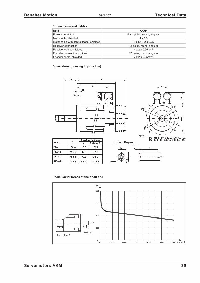
Connections and cables
Data AKM4
Power connection 4 + 4 poles, round, angular
Motorcable, shielded 4 x 1.5
Motor cable with control leads, shielded 4 x 1.5 + 2 x 0.75
Resolver connection 12 poles, round, angular
Resolver cable, shielded 4 x 2 x 0.25mm²
Encoder connection (option) 17 poles, round, angular
Encoder cable, shielded 7 x 2 x 0.25mm²
Dimensions (drawing in principle)
Radial-/axial forces at the shaft end
Servomotors AKM 35
Danaher Motion 09/2007 Technical Data
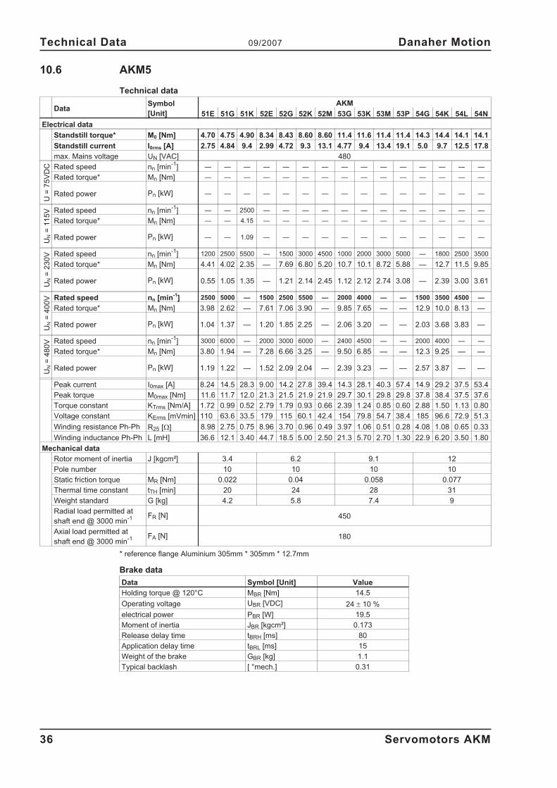
10.6 AKM5
Technical data
DataSymbol
[Unit]
AKM
51E 51G 51K 52E 52G 52K 52M 53G 53K 53M 53P 54G 54K 54L 54N
Electrical data
Standstill torque* M0 [Nm] 4.70 4.75 4.90 8.34 8.43 8.60 8.60 11.4 11.6 11.4 11.4 14.3 14.4 14.1 14.1
Standstill current I0rms [A] 2.75 4.84 9.4 2.99 4.72 9.3 13.1 4.77 9.4 13.4 19.1 5.0 9.7 12.5 17.8
max. Mains voltage UN [VAC] 480
U=
75
VD
C Rated speed nn [min-1
] — — — — — — — — — — — — — — —
Rated torque* Mn [Nm] — — — — — — — — — — — — — — —
Rated power Pn [kW] — — — — — — — — — — — — — — —
UN
=1
15
V Rated speed nn [min-1
] — — 2500 — — — — — — — — — — — —
Rated torque* Mn [Nm] — — 4.15 — — — — — — — — — — — —
Rated power Pn [kW] — — 1.09 — — — — — — — — — — — —
UN
=2
30
V Rated speed nn [min-1
] 1200 2500 5500 — 1500 3000 4500 1000 2000 3000 5000 — 1800 2500 3500
Rated torque* Mn [Nm] 4.41 4.02 2.35 — 7.69 6.80 5.20 10.7 10.1 8.72 5.88 — 12.7 11.5 9.85
Rated power Pn [kW] 0.55 1.05 1.35 — 1.21 2.14 2.45 1.12 2.12 2.74 3.08 — 2.39 3.00 3.61
UN
=4
00
V Rated speed nn [min-1
] 2500 5000 — 1500 2500 5500 — 2000 4000 — — 1500 3500 4500 —
Rated torque* Mn [Nm] 3.98 2.62 — 7.61 7.06 3.90 — 9.85 7.65 — — 12.9 10.0 8.13 —
Rated power Pn [kW] 1.04 1.37 — 1.20 1.85 2.25 — 2.06 3.20 — — 2.03 3.68 3.83 —
UN
=4
80
V Rated speed nn [min-1
] 3000 6000 — 2000 3000 6000 — 2400 4500 — — 2000 4000 — —
Rated torque* Mn [Nm] 3.80 1.94 — 7.28 6.66 3.25 — 9.50 6.85 — — 12.3 9.25 — —
Rated power Pn [kW] 1.19 1.22 — 1.52 2.09 2.04 — 2.39 3.23 — — 2.57 3.87 — —
Peak current I0max [A] 8.24 14.5 28.3 9.00 14.2 27.8 39.4 14.3 28.1 40.3 57.4 14.9 29.2 37.5 53.4
Peak torque M0max [Nm] 11.6 11.7 12.0 21.3 21.5 21.9 21.9 29.7 30.1 29.8 29.8 37.8 38.4 37.5 37.6
Torque constant KTrms [Nm/A] 1.72 0.99 0.52 2.79 1.79 0.93 0.66 2.39 1.24 0.85 0.60 2.88 1.50 1.13 0.80
Voltage constant KErms [mVmin] 110 63.6 33.5 179 115 60.1 42.4 154 79.8 54.7 38.4 185 96.6 72.9 51.3
Winding resistance Ph-Ph R25 [�] 8.98 2.75 0.75 8.96 3.70 0.96 0.49 3.97 1.06 0.51 0.28 4.08 1.08 0.65 0.33
Winding inductance Ph-Ph L [mH] 36.6 12.1 3.40 44.7 18.5 5.00 2.50 21.3 5.70 2.70 1.30 22.9 6.20 3.50 1.80
Mechanical data
Rotor moment of inertia J [kgcm²] 3.4 6.2 9.1 12
Pole number 10 10 10 10
Static friction torque MR [Nm] 0.022 0.04 0.058 0.077
Thermal time constant tTH [min] 20 24 28 31
Weight standard G [kg] 4.2 5.8 7.4 9
Radial load permitted at
shaft end @ 3000 min-1 FR [N] 450
Axial load permitted at
shaft end @ 3000 min-1 FA [N] 180
* reference flange Aluminium 305mm * 305mm * 12.7mm
Brake data
Data Symbol [Unit] Value
Holding torque @ 120°C MBR [Nm] 14.5
Operating voltage UBR [VDC] 24 � 10 %
electrical power PBR [W] 19.5
Moment of inertia JBR [kgcm²] 0.173
Release delay time tBRH [ms] 80
Application delay time tBRL [ms] 15
Weight of the brake GBR [kg] 1.1
Typical backlash [ °mech.] 0.31
36 Servomotors AKM
Technical Data 09/2007 Danaher Motion
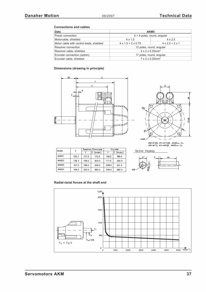
Connections and cables
Data AKM5
Power connection 4 + 4 poles, round, angular
Motorcable, shielded 4 x 1.5 4 x 2.5
Motor cable with control leads, shielded 4 x 1.5 + 2 x 0.75 4 x 2.5 + 2 x 1
Resolver connection 12 poles, round, angular
Resolver cable, shielded 4 x 2 x 0.25mm²
Encoder connection (option) 17 poles, round, angular
Encoder cable, shielded 7 x 2 x 0.25mm²
Dimensions (drawing in principle)
Radial-/axial forces at the shaft end
Servomotors AKM 37
Danaher Motion 09/2007 Technical Data
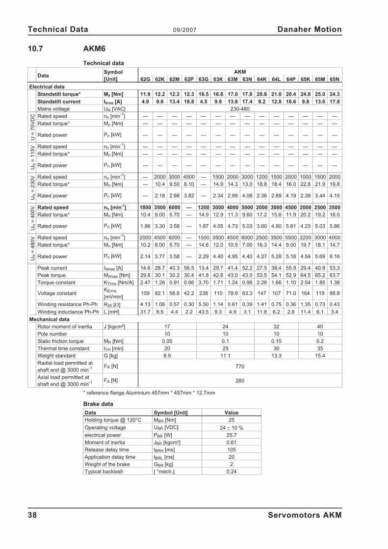
10.7 AKM6
Technical data
DataSymbol
[Unit]
AKM
62G 62K 62M 62P 63G 63K 63M 63N 64K 64L 64P 65K 65M 65N
Electrical data
Standstill torque* M0 [Nm] 11.9 12.2 12.2 12.3 16.5 16.8 17.0 17.0 20.8 21.0 20.4 24.8 25.0 24.3
Standstill current I0rms [A] 4.9 9.6 13.4 18.8 4.5 9.9 13.8 17.4 9.2 12.8 18.6 9.8 13.6 17.8
Mains voltage UN [VAC] 230-480
U=
75
VD
C Rated speed nn [min-1
] — — — — — — — — — — — — — —
Rated torque* Mn [Nm] — — — — — — — — — — — — — —
Rated power Pn [kW] — — — — — — — — — — — — — —
UN
=1
15
V Rated speed nn [min-1
] — — — — — — — — — — — — — —
Rated torque* Mn [Nm] — — — — — — — — — — — — — —
Rated power Pn [kW] — — — — — — — — — — — — — —
UN
=2
30
V Rated speed nn [min-1
] — 2000 3000 4500 — 1500 2000 3000 1200 1500 2500 1000 1500 2000
Rated torque* Mn [Nm] — 10.4 9.50 8.10 — 14.9 14.3 13.0 18.8 18.4 16.0 22.8 21.9 19.8
Rated power Pn [kW] — 2.18 2.98 3.82 — 2.34 2.99 4.08 2.36 2.89 4.19 2.39 3.44 4.15
UN
=4
00
V Rated speed nn [min-1
] 1800 3500 6000 — 1200 3000 4000 5000 2000 3000 4500 2000 2500 3500
Rated torque* Mn [Nm] 10.4 9.00 5.70 — 14.9 12.9 11.3 9.60 17.2 15.6 11.9 20.2 19.2 16.0
Rated power Pn [kW] 1.96 3.30 3.58 — 1.87 4.05 4.73 5.03 3.60 4.90 5.61 4.23 5.03 5.86
UN
=4
80
V Rated speed nn [min-1
] 2000 4500 6000 — 1500 3500 4500 6000 2500 3500 5500 2200 3000 4000
Rated torque* Mn [Nm] 10.2 8.00 5.70 — 14.6 12.0 10.5 7.00 16.3 14.4 9.00 19.7 18.1 14.7
Rated power Pn [kW] 2.14 3.77 3.58 — 2.29 4.40 4.95 4.40 4.27 5.28 5.18 4.54 5.69 6.16
Peak current I0max [A] 14.6 28.7 40.3 56.5 13.4 29.7 41.4 52.2 27.5 38.4 55.9 29.4 40.9 53.3
Peak torque M0max [Nm] 29.8 30.1 30.2 30.4 41.8 42.6 43.0 43.0 53.5 54.1 52.9 64.5 65.2 63.7
Torque constant KTrms [Nm/A] 2.47 1.28 0.91 0.66 3.70 1.71 1.24 0.98 2.28 1.66 1.10 2.54 1.85 1.38
Voltage constantKErms
[mVmin]159 82.1 58.8 42.2 238 110 79.9 63.3 147 107 71.0 164 119 88.8
Winding resistance Ph-Ph R25 [�] 4.13 1.08 0.57 0.30 5.50 1.14 0.61 0.39 1.41 0.75 0.36 1.35 0.73 0.43
Winding inductance Ph-Ph L [mH] 31.7 8.5 4.4 2.2 43.5 9.3 4.9 3.1 11.8 6.2 2.8 11.4 6.1 3.4
Mechanical data
Rotor moment of inertia J [kgcm²] 17 24 32 40
Pole number 10 10 10 10
Static friction torque MR [Nm] 0.05 0.1 0.15 0.2
Thermal time constant tTH [min] 20 25 30 35
Weight standard G [kg] 8.9 11.1 13.3 15.4
Radial load permitted at
shaft end @ 3000 min-1 FR [N] 770
Axial load permitted at
shaft end @ 3000 min-1 FA [N] 280
* reference flange Aluminium 457mm * 457mm * 12.7mm
Brake data
Data Symbol [Unit] Value
Holding torque @ 120°C MBR [Nm] 25
Operating voltage UBR [VDC] 24 � 10 %
electrical power PBR [W] 25.7
Moment of inertia JBR [kgcm²] 0.61
Release delay time tBRH [ms] 105
Application delay time tBRL [ms] 20
Weight of the brake GBR [kg] 2
Typical backlash [ °mech.] 0.24
38 Servomotors AKM
Technical Data 09/2007 Danaher Motion
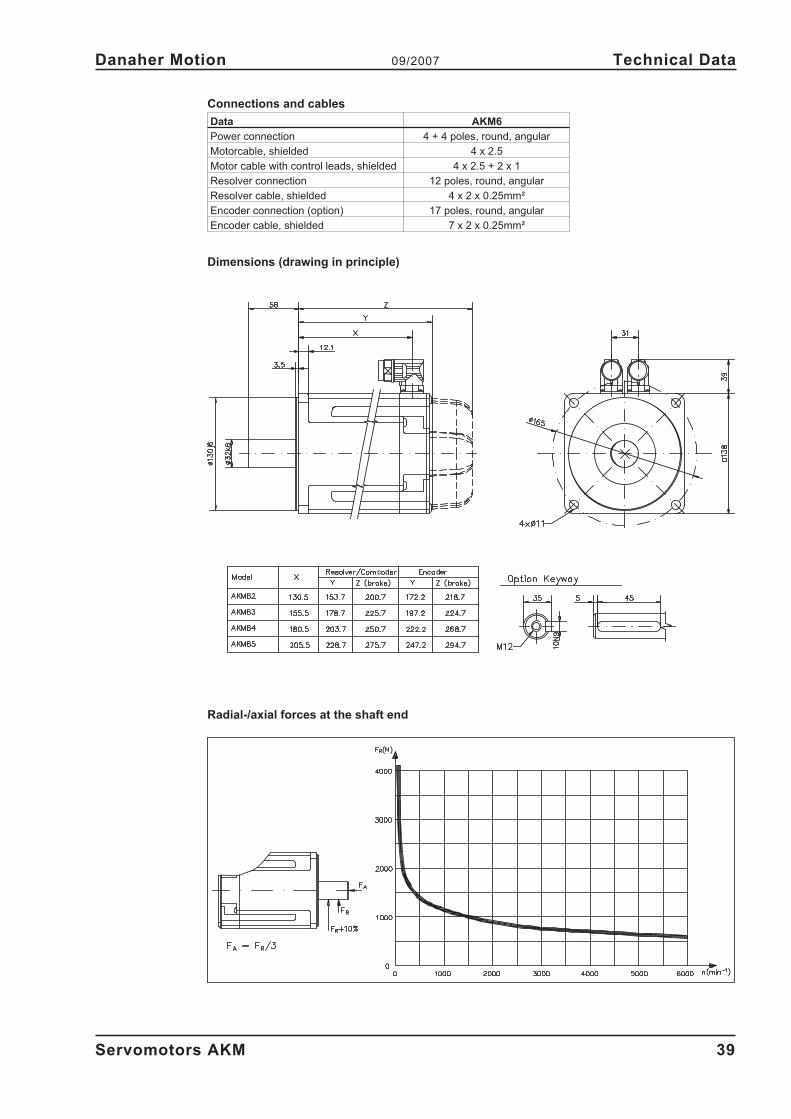
Connections and cables
Data AKM6
Power connection 4 + 4 poles, round, angular
Motorcable, shielded 4 x 2.5
Motor cable with control leads, shielded 4 x 2.5 + 2 x 1
Resolver connection 12 poles, round, angular
Resolver cable, shielded 4 x 2 x 0.25mm²
Encoder connection (option) 17 poles, round, angular
Encoder cable, shielded 7 x 2 x 0.25mm²
Dimensions (drawing in principle)
Radial-/axial forces at the shaft end
Servomotors AKM 39
Danaher Motion 09/2007 Technical Data
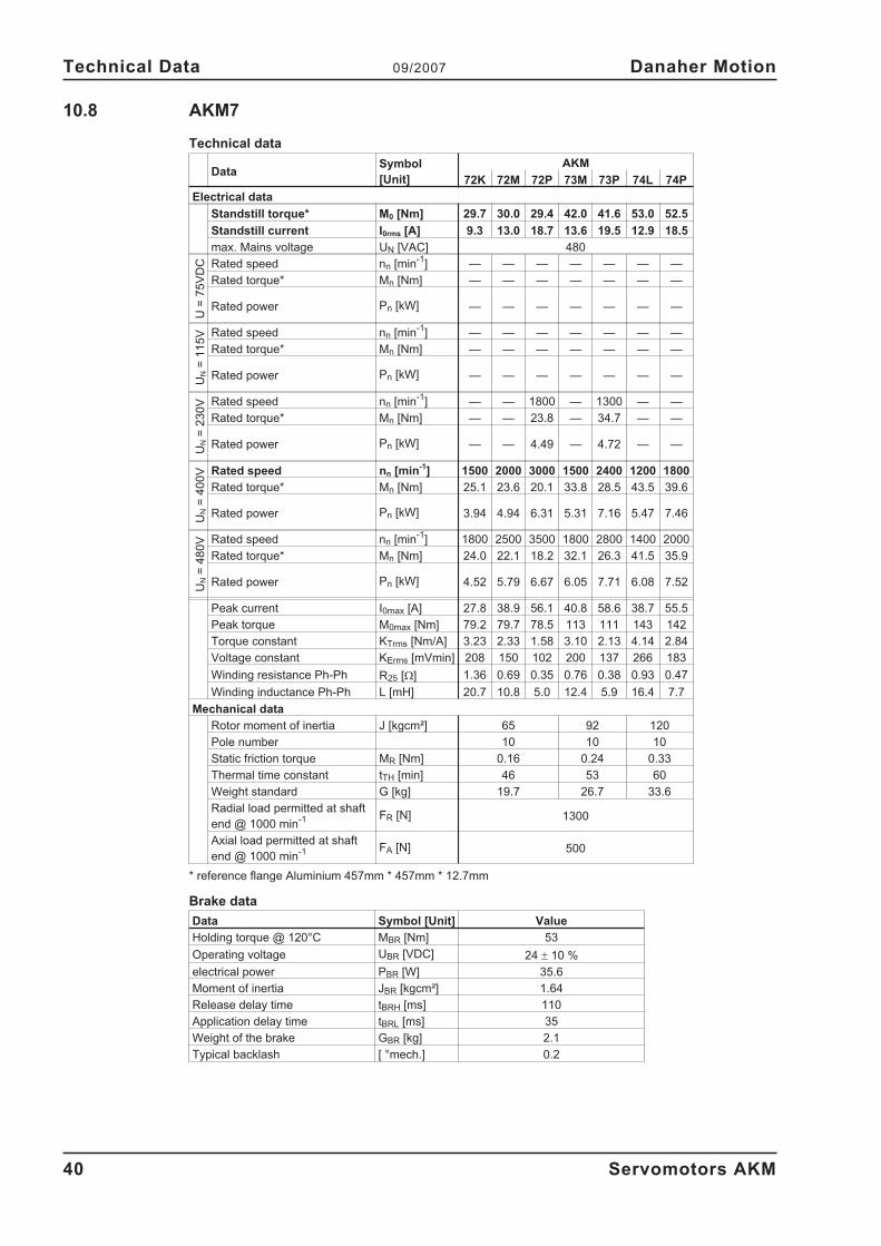
10.8 AKM7
Technical data
DataSymbol
[Unit]
AKM
72K 72M 72P 73M 73P 74L 74P
Electrical data
Standstill torque* M0 [Nm] 29.7 30.0 29.4 42.0 41.6 53.0 52.5
Standstill current I0rms [A] 9.3 13.0 18.7 13.6 19.5 12.9 18.5
max. Mains voltage UN [VAC] 480
U=
75
VD
C Rated speed nn [min-1
] — — — — — — —
Rated torque* Mn [Nm] — — — — — — —
Rated power Pn [kW] — — — — — — —
UN
=1
15
V Rated speed nn [min-1
] — — — — — — —
Rated torque* Mn [Nm] — — — — — — —
Rated power Pn [kW] — — — — — — —
UN
=2
30
V Rated speed nn [min-1
] — — 1800 — 1300 — —
Rated torque* Mn [Nm] — — 23.8 — 34.7 — —
Rated power Pn [kW] — — 4.49 — 4.72 — —
UN
=4
00
V Rated speed nn [min-1
] 1500 2000 3000 1500 2400 1200 1800
Rated torque* Mn [Nm] 25.1 23.6 20.1 33.8 28.5 43.5 39.6
Rated power Pn [kW] 3.94 4.94 6.31 5.31 7.16 5.47 7.46
UN
=4
80
V Rated speed nn [min-1
] 1800 2500 3500 1800 2800 1400 2000
Rated torque* Mn [Nm] 24.0 22.1 18.2 32.1 26.3 41.5 35.9
Rated power Pn [kW] 4.52 5.79 6.67 6.05 7.71 6.08 7.52
Peak current I0max [A] 27.8 38.9 56.1 40.8 58.6 38.7 55.5
Peak torque M0max [Nm] 79.2 79.7 78.5 113 111 143 142
Torque constant KTrms [Nm/A] 3.23 2.33 1.58 3.10 2.13 4.14 2.84
Voltage constant KErms [mVmin] 208 150 102 200 137 266 183
Winding resistance Ph-Ph R25 [�] 1.36 0.69 0.35 0.76 0.38 0.93 0.47
Winding inductance Ph-Ph L [mH] 20.7 10.8 5.0 12.4 5.9 16.4 7.7
Mechanical data
Rotor moment of inertia J [kgcm²] 65 92 120
Pole number 10 10 10
Static friction torque MR [Nm] 0.16 0.24 0.33
Thermal time constant tTH [min] 46 53 60
Weight standard G [kg] 19.7 26.7 33.6
Radial load permitted at shaft
end @ 1000 min-1 FR [N] 1300
Axial load permitted at shaft
end @ 1000 min-1 FA [N] 500
* reference flange Aluminium 457mm * 457mm * 12.7mm
Brake data
Data Symbol [Unit] Value
Holding torque @ 120°C MBR [Nm] 53
Operating voltage UBR [VDC] 24 � 10 %
electrical power PBR [W] 35.6
Moment of inertia JBR [kgcm²] 1.64
Release delay time tBRH [ms] 110
Application delay time tBRL [ms] 35
Weight of the brake GBR [kg] 2.1
Typical backlash [ °mech.] 0.2
40 Servomotors AKM
Technical Data 09/2007 Danaher Motion
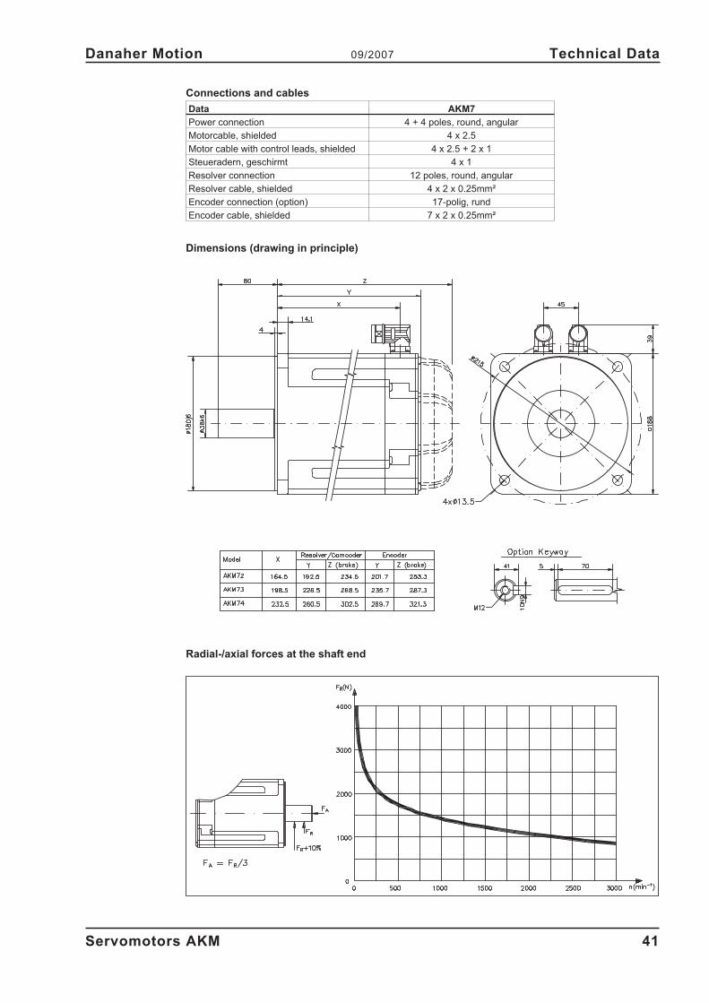
Connections and cables
Data AKM7
Power connection 4 + 4 poles, round, angular
Motorcable, shielded 4 x 2.5
Motor cable with control leads, shielded 4 x 2.5 + 2 x 1
Steueradern, geschirmt 4 x 1
Resolver connection 12 poles, round, angular
Resolver cable, shielded 4 x 2 x 0.25mm²
Encoder connection (option) 17-polig, rund
Encoder cable, shielded 7 x 2 x 0.25mm²
Dimensions (drawing in principle)
Radial-/axial forces at the shaft end
Servomotors AKM 41
Danaher Motion 09/2007 Technical Data

This page has been deliberately left blank.
42 Servomotors AKM
Technical Data 09/2007 Danaher Motion
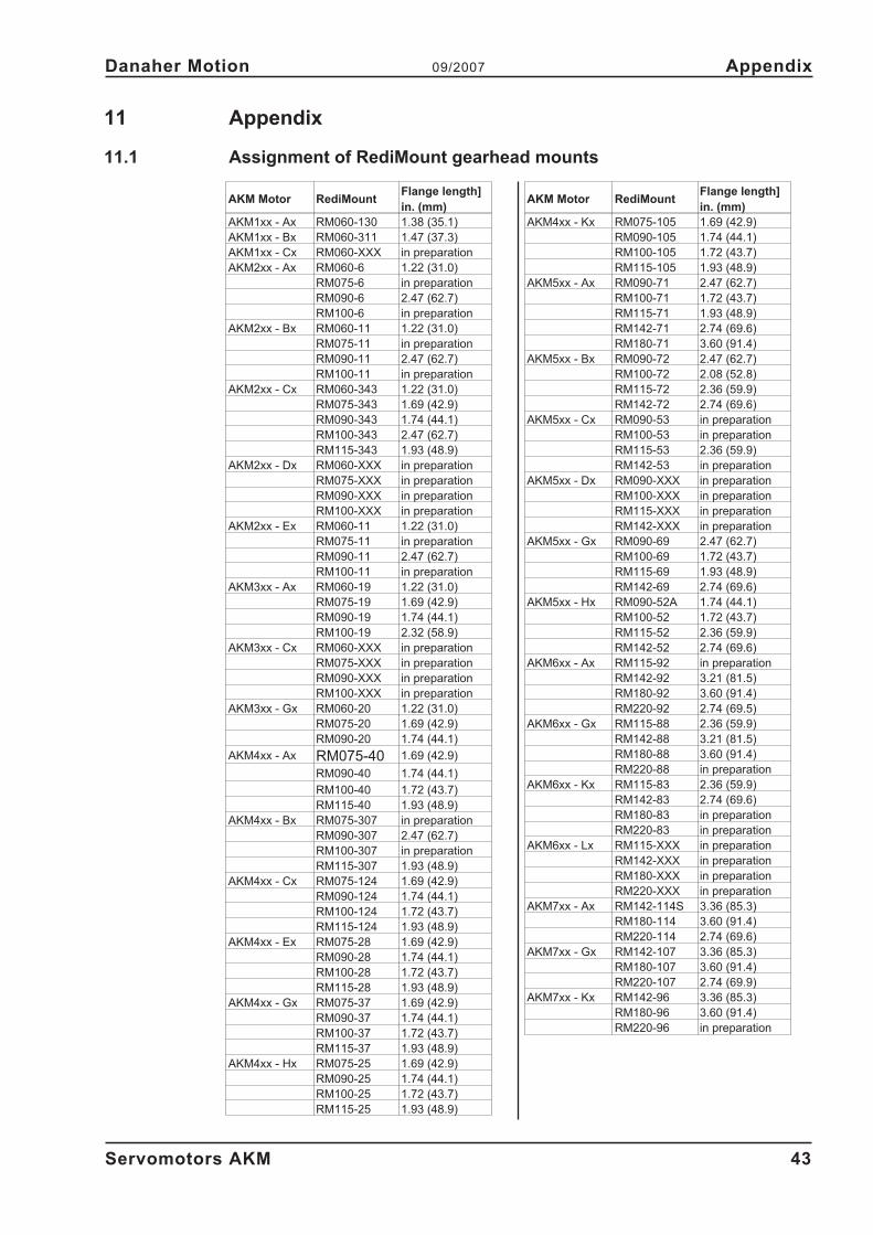
11 Appendix
11.1 Assignment of RediMount gearhead mounts
Servomotors AKM 43
Danaher Motion 09/2007 Appendix
AKM Motor RediMountFlange length]
in. (mm)
AKM1xx - Ax RM060-130 1.38 (35.1)
AKM1xx - Bx RM060-311 1.47 (37.3)
AKM1xx - Cx RM060-XXX in preparation
AKM2xx - Ax RM060-6 1.22 (31.0)
RM075-6 in preparation
RM090-6 2.47 (62.7)
RM100-6 in preparation
AKM2xx - Bx RM060-11 1.22 (31.0)
RM075-11 in preparation
RM090-11 2.47 (62.7)
RM100-11 in preparation
AKM2xx - Cx RM060-343 1.22 (31.0)
RM075-343 1.69 (42.9)
RM090-343 1.74 (44.1)
RM100-343 2.47 (62.7)
RM115-343 1.93 (48.9)
AKM2xx - Dx RM060-XXX in preparation
RM075-XXX in preparation
RM090-XXX in preparation
RM100-XXX in preparation
AKM2xx - Ex RM060-11 1.22 (31.0)
RM075-11 in preparation
RM090-11 2.47 (62.7)
RM100-11 in preparation
AKM3xx - Ax RM060-19 1.22 (31.0)
RM075-19 1.69 (42.9)
RM090-19 1.74 (44.1)
RM100-19 2.32 (58.9)
AKM3xx - Cx RM060-XXX in preparation
RM075-XXX in preparation
RM090-XXX in preparation
RM100-XXX in preparation
AKM3xx - Gx RM060-20 1.22 (31.0)
RM075-20 1.69 (42.9)
RM090-20 1.74 (44.1)
AKM4xx - Ax RM075-40 1.69 (42.9)
RM090-40 1.74 (44.1)
RM100-40 1.72 (43.7)
RM115-40 1.93 (48.9)
AKM4xx - Bx RM075-307 in preparation
RM090-307 2.47 (62.7)
RM100-307 in preparation
RM115-307 1.93 (48.9)
AKM4xx - Cx RM075-124 1.69 (42.9)
RM090-124 1.74 (44.1)
RM100-124 1.72 (43.7)
RM115-124 1.93 (48.9)
AKM4xx - Ex RM075-28 1.69 (42.9)
RM090-28 1.74 (44.1)
RM100-28 1.72 (43.7)
RM115-28 1.93 (48.9)
AKM4xx - Gx RM075-37 1.69 (42.9)
RM090-37 1.74 (44.1)
RM100-37 1.72 (43.7)
RM115-37 1.93 (48.9)
AKM4xx - Hx RM075-25 1.69 (42.9)
RM090-25 1.74 (44.1)
RM100-25 1.72 (43.7)
RM115-25 1.93 (48.9)
AKM Motor RediMountFlange length]
in. (mm)
AKM4xx - Kx RM075-105 1.69 (42.9)
RM090-105 1.74 (44.1)
RM100-105 1.72 (43.7)
RM115-105 1.93 (48.9)
AKM5xx - Ax RM090-71 2.47 (62.7)
RM100-71 1.72 (43.7)
RM115-71 1.93 (48.9)
RM142-71 2.74 (69.6)
RM180-71 3.60 (91.4)
AKM5xx - Bx RM090-72 2.47 (62.7)
RM100-72 2.08 (52.8)
RM115-72 2.36 (59.9)
RM142-72 2.74 (69.6)
AKM5xx - Cx RM090-53 in preparation
RM100-53 in preparation
RM115-53 2.36 (59.9)
RM142-53 in preparation
AKM5xx - Dx RM090-XXX in preparation
RM100-XXX in preparation
RM115-XXX in preparation
RM142-XXX in preparation
AKM5xx - Gx RM090-69 2.47 (62.7)
RM100-69 1.72 (43.7)
RM115-69 1.93 (48.9)
RM142-69 2.74 (69.6)
AKM5xx - Hx RM090-52A 1.74 (44.1)
RM100-52 1.72 (43.7)
RM115-52 2.36 (59.9)
RM142-52 2.74 (69.6)
AKM6xx - Ax RM115-92 in preparation
RM142-92 3.21 (81.5)
RM180-92 3.60 (91.4)
RM220-92 2.74 (69.5)
AKM6xx - Gx RM115-88 2.36 (59.9)
RM142-88 3.21 (81.5)
RM180-88 3.60 (91.4)
RM220-88 in preparation
AKM6xx - Kx RM115-83 2.36 (59.9)
RM142-83 2.74 (69.6)
RM180-83 in preparation
RM220-83 in preparation
AKM6xx - Lx RM115-XXX in preparation
RM142-XXX in preparation
RM180-XXX in preparation
RM220-XXX in preparation
AKM7xx - Ax RM142-114S 3.36 (85.3)
RM180-114 3.60 (91.4)
RM220-114 2.74 (69.6)
AKM7xx - Gx RM142-107 3.36 (85.3)
RM180-107 3.60 (91.4)
RM220-107 2.74 (69.9)
AKM7xx - Kx RM142-96 3.36 (85.3)
RM180-96 3.60 (91.4)
RM220-96 in preparation
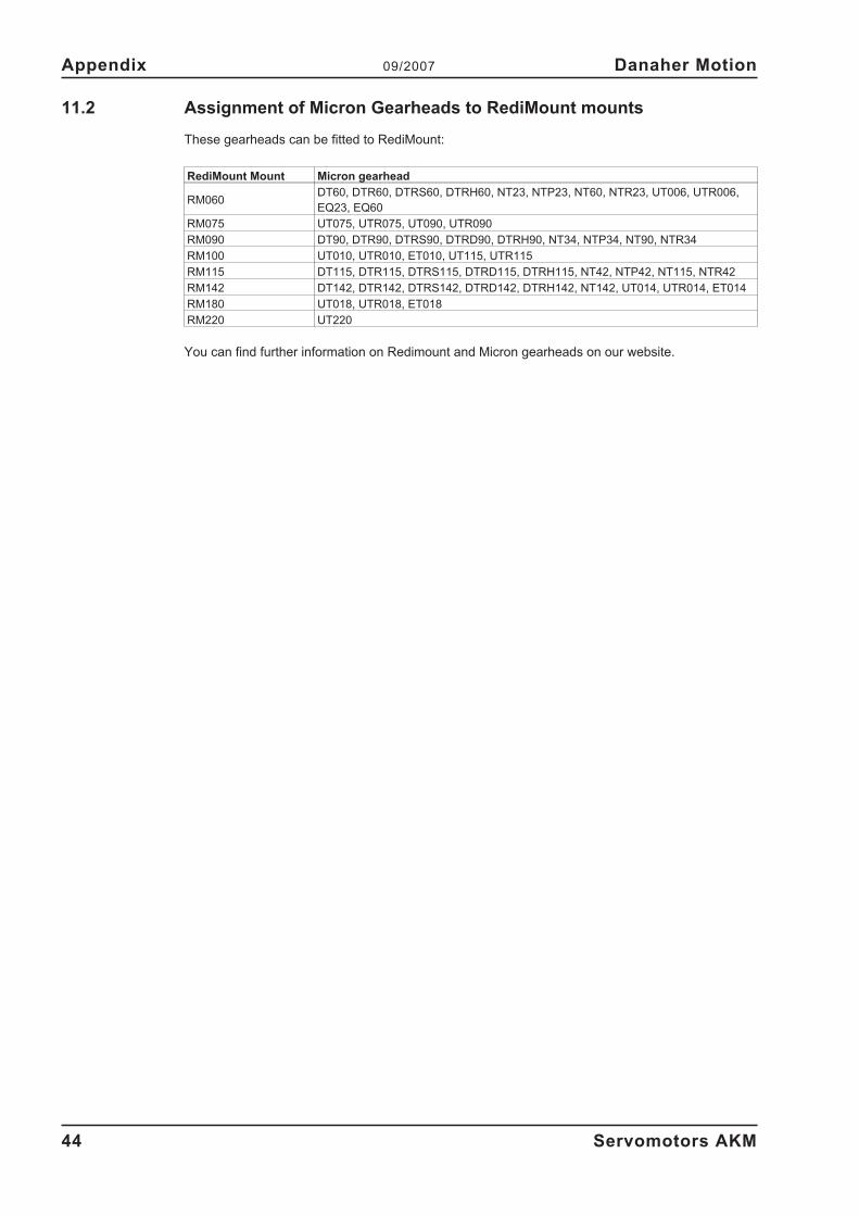
11.2 Assignment of Micron Gearheads to RediMount mounts
These gearheads can be fitted to RediMount:
RediMount Mount Micron gearhead
RM060DT60, DTR60, DTRS60, DTRH60, NT23, NTP23, NT60, NTR23, UT006, UTR006,
EQ23, EQ60
RM075 UT075, UTR075, UT090, UTR090
RM090 DT90, DTR90, DTRS90, DTRD90, DTRH90, NT34, NTP34, NT90, NTR34
RM100 UT010, UTR010, ET010, UT115, UTR115
RM115 DT115, DTR115, DTRS115, DTRD115, DTRH115, NT42, NTP42, NT115, NTR42
RM142 DT142, DTR142, DTRS142, DTRD142, DTRH142, NT142, UT014, UTR014, ET014
RM180 UT018, UTR018, ET018
RM220 UT220
You can find further information on Redimount and Micron gearheads on our website.
44 Servomotors AKM
Appendix 09/2007 Danaher Motion
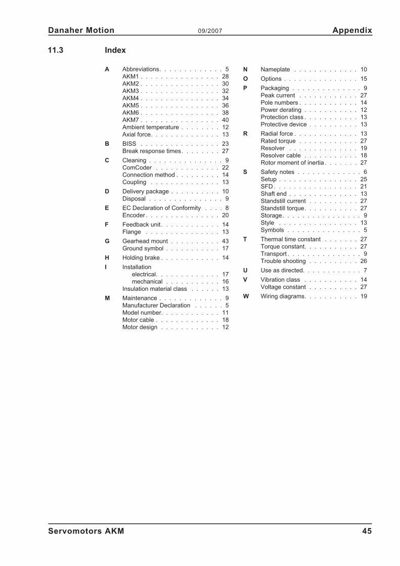
11.3 Index
Servomotors AKM 45
Danaher Motion 09/2007 Appendix
IndexA Abbreviations. . . . . . . . . . . . . 5
AKM1 . . . . . . . . . . . . . . . . 28
AKM2 . . . . . . . . . . . . . . . . 30
AKM3 . . . . . . . . . . . . . . . . 32
AKM4 . . . . . . . . . . . . . . . . 34
AKM5 . . . . . . . . . . . . . . . . 36
AKM6 . . . . . . . . . . . . . . . . 38
AKM7 . . . . . . . . . . . . . . . . 40
Ambient temperature . . . . . . . . 12
Axial force. . . . . . . . . . . . . . 13
B BISS . . . . . . . . . . . . . . . . 23
Break response times. . . . . . . . 27
C Cleaning . . . . . . . . . . . . . . . 9
ComCoder . . . . . . . . . . . . . 22
Connection method . . . . . . . . . 14
Coupling . . . . . . . . . . . . . . 13
D Delivery package . . . . . . . . . . 10
Disposal . . . . . . . . . . . . . . . 9
E EC Declaration of Conformity . . . . 8
Encoder . . . . . . . . . . . . . . . 20
F Feedback unit . . . . . . . . . . . . 14
Flange . . . . . . . . . . . . . . . 13
G Gearhead mount . . . . . . . . . . 43
Ground symbol . . . . . . . . . . . 17
H Holding brake . . . . . . . . . . . . 14
I Installation
electrical. . . . . . . . . . . . . 17
mechanical . . . . . . . . . . . 16
Insulation material class . . . . . . 13
M Maintenance . . . . . . . . . . . . . 9
Manufacturer Declaration . . . . . . 5
Model number. . . . . . . . . . . . 11
Motor cable . . . . . . . . . . . . . 18
Motor design . . . . . . . . . . . . 12
N Nameplate . . . . . . . . . . . . . 10
O Options . . . . . . . . . . . . . . . 15
P Packaging . . . . . . . . . . . . . . 9
Peak current . . . . . . . . . . . . 27
Pole numbers . . . . . . . . . . . . 14
Power derating . . . . . . . . . . . 12
Protection class . . . . . . . . . . . 13
Protective device . . . . . . . . . . 13
R Radial force . . . . . . . . . . . . . 13
Rated torque . . . . . . . . . . . . 27
Resolver . . . . . . . . . . . . . . 19
Resolver cable . . . . . . . . . . . 18
Rotor moment of inertia . . . . . . . 27
S Safety notes . . . . . . . . . . . . . 6
Setup . . . . . . . . . . . . . . . . 25
SFD . . . . . . . . . . . . . . . . . 21
Shaft end . . . . . . . . . . . . . . 13
Standstill current . . . . . . . . . . 27
Standstill torque. . . . . . . . . . . 27
Storage. . . . . . . . . . . . . . . . 9
Style . . . . . . . . . . . . . . . . 13
Symbols . . . . . . . . . . . . . . . 5
T Thermal time constant . . . . . . . 27
Torque constant. . . . . . . . . . . 27
Transport . . . . . . . . . . . . . . . 9
Trouble shooting . . . . . . . . . . 26
U Use as directed. . . . . . . . . . . . 7
V Vibration class . . . . . . . . . . . 14
Voltage constant . . . . . . . . . . 27
W Wiring diagrams. . . . . . . . . . . 19
Sales and Service
We are committed to quality customer service. In order to serve in the most effective way,
please contact your local sales representative for assistance.
If you are unaware of your local sales representative, please contact us.
Europe
Danaher Motion Customer Support Europe
E-Mail [email protected]
Internet www.DanaherMotion.net
Tel.: +49(0)203 - 99 79 - 0
Fax: +49(0)203 - 99 79 - 216
North America
Danaher Motion Customer Support North America
Internet www.DanaherMotion.com
E-Mail [email protected]
Phone: +1 - 540 - 633 - 3400
Fax: +1 - 540 - 639 - 4162