Aker Solutions’ Carbon Capture Technology – Improving ... · carbonate looping, etc. September...
17
Aker Solutions’ Carbon Capture Technology – Improving Absorption Technology HiPerCap Workshop, September 13, 2017 Jacob Nygaard Knudsen, Project Manager CCUS, Aker Solutions Slide 1
Transcript of Aker Solutions’ Carbon Capture Technology – Improving ... · carbonate looping, etc. September...

Public © 2017 Aker Solutions
Aker Solutions’ Carbon Capture Technology –Improving Absorption Technology
HiPerCap Workshop, September 13, 2017Jacob Nygaard Knudsen, Project Manager CCUS, Aker Solutions
Slide 1

Public © 2017 Aker Solutions
Carbon Capture, Utilization and Storage (CCUS)
Slide 2
Aker Solutions offers technology and solutions for the entire carbon capture, utilization and storage value chain

Public © 2017 Aker Solutions
Carbon Capture Technology, Process Design and Equipment
Slide 3
Advanced Carbon CaptureTM ProcessFull scale plant and process design, specification and delivery of proprietary equipment packages, solvent formulation, performance guarantees and licencing of technology. EPC partnering.
Technology Characteristics Excellent performance data from coal, gas, cement and
waste-to-energy plants 50 000 operating hours in six pilot plants globally Cost, energy and environmental focus Modularization
Key Equipment Absorber Tower Desorber incl. reboiler Direct contact cooler Reclaimer Energy Saver
Generic Flow Diagram
Technology advantages Most mature Flexibility For retrofit and new built For various flue gases Lifecycle cost Verified improvements Excellent solvent performance

Public © 2017 Aker Solutions
■ Participation in many Norwegian and international research projects■ Large 8-year R&D program SOLVit to improve solvents and process technology■ Operation of Aker Solutions’ Mobile Test Unit (MTU) since 2008 at various industrial emission
sources■ Test & demonstration for 2 years at Technology Centre Mongstad (TCM)■ Comprehensive technology qualification programme executed■ Design matured through numerous engineering studies (CCM, Norcem CCS, Longgannet, Kårstø
Demo, Port Tolle, etc.)
Slide 4
Development and Qualification of ACCTM Technology
Develop Test Improve Deploy
Sleipner Field Kårstø Demo Study
Mobile Test Unit (MTU)
Large Scale Pilot TCM
Kårstø CO2 PilotNTNU/SINTEF Lab Rig
1996 1996 1998 2007 2008 2012

Public © 2017 Aker Solutions
■ Owned & Operated by Aker Solutions ■ Test campaigns in industrial environment
since 2008 ■ Coal & gas power, refinery, cement industry
and W-t-E■ Over 20,000 operation hours
Slide 5
MTU, Mobile Test Unit | Advanced CO2 Capture Pilot
National CCCAlabama, US
Risavika & TCM Norway
ACCTM 1st at NCCC
2008 and 2012
ACCTM 1st at TCM
Longannet Power PlantScotland
2009
ACCTM 1st in UK
2011

Public © 2017 Aker Solutions
Improved Energy Efficiency (SOLVit)■ A reduction of the energy
consumption with 10-25% has been demonstrated in pilot plants with SOLVit solvents, compared to project references “Bellingham plant“ (NG) and Esbjerg pilot plant (Coal) using MEA
■ Applying an advanced process flow sheet increases energy saving of SOLVit solvents with up to 35% compared to reference
September 22, 2017 Slide 6
-35%

Public © 2017 Aker Solutions
■ Green solvents with improved HSE characteristics (non-toxic, nonhazardous for aquatic organisms, ready biodegradable, etc.) developed in SOLVit
■ Consumption of MEA is almost 5 and 10 times higher than that of CC2 and CCx2, respectively, demonstrating the superior degradation resistance of the solvents developed in SOLVit
■ Degradation rate (heat stable salts) in SOLVit solvents (especially for CCx2) remain very low after 3,300 operation hours
September 22, 2017 Slide 7
Improved Solvent HSE and Degradation Performance
Solvent Total solvent loss(kg amine/ton CO2)
MEA 2.6
CC2 0.6
CCx2 0.3
MEACC2
CCx2Reclaiming
Results from testing of SOLVit solvents at TCM

Public © 2017 Aker Solutions
Reduced Formation of Harmful Degradation Products
■ CC2 and CCx2 are developed to be green solvents that is solvents with similar or better HSE performance than MEA
■ Miniscule formation of harmful degradation products such as nitrosamines and nitramines
Slide 8
MEA
CC2
CCx2
Nitrosamine formation in solvent during long-term test campaigns at TCM

Public © 2017 Aker Solutions
■ Very low emission of solvent amines (<1 mg/Nm3) with optimized water wash sections
■ Low emission of ammonia and other volatile degradation products (e.g. alkyl amines) from selection of amines with low oxidative degradation rate
■ Emissions of amine mist can be virtually eliminated with the ACC™ anti-mist design
■ Control of nitrosamine emission through selection of amines that does not readily form nitrosamines
■ If desirable, emissions of alkaline components can be almost completely eliminated (<0.01 mg/Nm3) with acid wash
September 22, 2017 Slide 9
Improved Emission ControlConventionaloperation
Conventionaloperation
Anti-mist operation
Anti-mist operationAnti-mist
operation
MTU test of anti-mist design at NCCC, Alabama
MTU emission sampling at Norcem, Brevik
Public © 2017 Aker Solutions
Investigation of New Concepts for Further Improvement of Absorption Technology
Slide 10
Public © 2017 Aker Solutions
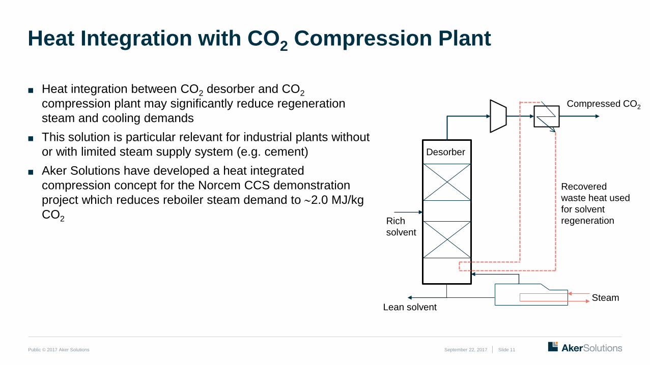
■ Heat integration between CO2 desorber and CO2compression plant may significantly reduce regeneration steam and cooling demands
■ This solution is particular relevant for industrial plants without or with limited steam supply system (e.g. cement)
■ Aker Solutions have developed a heat integrated compression concept for the Norcem CCS demonstration project which reduces reboiler steam demand to ∼2.0 MJ/kg CO2
September 22, 2017 Slide 11
Heat Integration with CO2 Compression Plant
Compressed CO2
Recovered waste heat used for solvent regeneration
Steam
Desorber
Rich solvent
Lean solvent

Public © 2017 Aker Solutions
Advanced heat integrated desorber developed and implemented in MTU (CLIMIT project “New desorber design”). Main test findings:■ Able to reduce SRD by 10% at typical desorber pressure,
and up to 14% reduction in SRD at slightly increased pressure (2-3 bara)
■ Learned that there is a limited room for low grade heat recovery, the desorption process can not utilise all low grade heat available
■ Other desorber configurations will not perform better, the limitations in low grade heat recovery are fundamental
■ However other solvents and higher desorber pressure may increase the potential for utilisation of low grade heat
September 22, 2017 Slide 12
Pilot Plant Test of Advanced Heat Integrated Desorber
Advanced desorber being installed at MTU

Public © 2017 Aker Solutions
■ Many promising biphasic solvent systems identified based on CO2 absorption/desorption screening tests and equilibrium data,
■ However many solvent systems were not feasible in practice■ Liquid two-phase systems (e.g. DEEA + MAPA) tested at
realistic conditions in the Tiller pilot plant at SINTEF■ Best energy numbers were obtained in test runs without
circulation of “light phase”■ Best energy number 2.7-3.0 GJ/ton, which is not significantly
better than with the best single phase solvents
September 22, 2017 Slide 13
Novel Biphasic Solvent Systems Tested in SOLVit
Biphasic solvent
Sketch capture plant for biphasic solvent

Public © 2017 Aker Solutions
Case Study:Using Absorption Technology for CO2 capture in the Cement Industry
Slide 14
Public © 2017 Aker Solutions
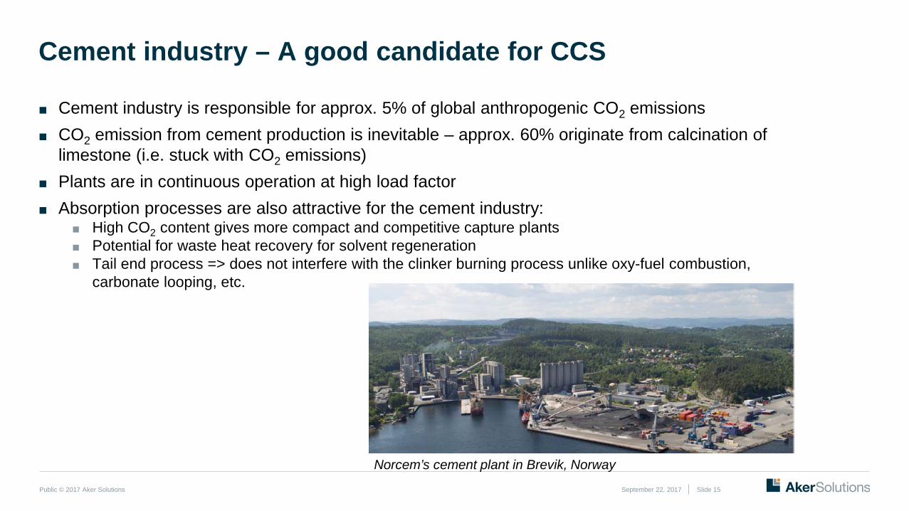
■ Cement industry is responsible for approx. 5% of global anthropogenic CO2 emissions■ CO2 emission from cement production is inevitable – approx. 60% originate from calcination of
limestone (i.e. stuck with CO2 emissions)■ Plants are in continuous operation at high load factor■ Absorption processes are also attractive for the cement industry:
■ High CO2 content gives more compact and competitive capture plants■ Potential for waste heat recovery for solvent regeneration■ Tail end process => does not interfere with the clinker burning process unlike oxy-fuel combustion,
carbonate looping, etc.
September 22, 2017 Slide 15
Cement industry – A good candidate for CCS
Norcem’s cement plant in Brevik, Norway
6%of global
emissions

Public © 2017 Aker Solutions September 22, 2017 Slide 16
Qualification of ACC™ Technology and Concept Development for a Cement Kiln - Norwegian CCS Demonstration at Norcem, Brevik
■ Performance of ACCTM capture technology has been verified during 18 months of pilot plant testing (MTU) at Norcem’scement plant in Brevik:
■ Stable operation on flue gas from cement kiln demonstrated■ Easy to obtain 90% CO2 capture due to high CO2 content in flue
gas (17-20%)■ No negative influence of capture plant performance observed
due to presence of trace level pollutants from the cement kiln ■ Low solvent degradation and emissions
■ Concept developed for a 400,000 tpa CO2 capture plant from the Brevik plant (nearly 50% of annual emissions) incl. compression, liquefaction, integration, intermittent CO2storage and ship loading
■ Capture plant driven solely by waste heat recovery from cement process and compression plant
Norcem: Part of HeidelbergCement Group One of three candidates for Norwegian CCS
demo project Aker Solutions is selected by Norcem as provider of
CO2 capture technology for a 400,000 tpa demo plant

Public © 2017 Aker Solutions
Copyright and disclaimerCopyrightCopyright of all published material including photographs, drawings and images in this document remains vested in Aker Solutions and third party contributors as appropriate. Accordingly, neither the whole nor any part of this document shall be reproduced in any form nor used in any manner without express prior permission and applicable acknowledgements. No trademark, copyright or other notice shall be altered or removed from any reproduction.
DisclaimerThis Presentation includes and is based, inter alia, on forward-looking information and statements that are subject to risks and uncertainties that could cause actual results to differ. These statements and this Presentation are based on current expectations, estimates and projections about global economic conditions, the economic conditions of the regions and industries that are major markets for Aker Solutions ASA and Aker Solutions ASA’s (including subsidiaries and affiliates) lines of business. These expectations, estimates and projections are generally identifiable by statements containing words such as “expects”, “believes”, “estimates” or similar expressions. Important factors that could cause actual results to differ materially from those expectations include, among others, economic and market conditions in the geographic areas and industries that are or will be major markets for Aker Solutions’ businesses, oil prices, market acceptance of new products and services, changes in governmental regulations, interest rates, fluctuations in currency exchange rates and such other factors as may be discussed from time to time in the Presentation. Although Aker Solutions ASA believes that its expectations and the Presentation are based upon reasonable assumptions, it can give no assurance that those expectations will be achieved or that the actual results will be as set out in the Presentation. Aker Solutions ASA is making no representation or warranty, expressed or implied, as to the accuracy, reliability or completeness of the Presentation, and neither Aker Solutions ASA nor any of its directors, officers or employees will have any liability to you or any other persons resulting from your use.
Aker Solutions consists of many legally independent entities, constituting their own separate identities. Aker Solutions is used as the common brand or trade mark for most of these entities. In this presentation we may sometimes use “Aker Solutions”, “we” or “us” when we refer to Aker Solutions companies in general or where no useful purpose is served by identifying any particular Aker Solutions company.
Slide 17