AK-SC255 Fact Sheet - Danfossfiles.danfoss.com/TechnicalInfo/Dila/01/DKRCE.PD.R1.B1.22_R-FACT... ·...
8
ELECTRONIC CONTROLS & SENSORS AK-SC255 Fact Sheet Version ‘R’ Software Software version 02_085
Transcript of AK-SC255 Fact Sheet - Danfossfiles.danfoss.com/TechnicalInfo/Dila/01/DKRCE.PD.R1.B1.22_R-FACT... ·...

ELECTRONIC CONTROLS& SENSORS
AK-SC255 Fact SheetVersion ‘R’ Software
Software version 02_085

What’s in the Box?1x AK-SC255 (either Box or DIN rail screen-less version)
What are the different part numbers?080Z2000 AK-SC255 Box, Color, TP78 Refrigeration080Z2001 AK-SC255 Box, Color, TP78 Lighting, HVAC080Z2002 AK-SC255 Box, Color, TP78 Refrigeration, Lighting, HVAC080Z2082 AK-SC255 No Display TP78, Refrigeration, Lighting, HVAC
Recommended Individual Controller capacity(s) per AK-SC255 - Generic + I/O
Type Capacity Configuration Type AK2-CC303a 60 Max configured evap sections 150 or Type EKC (SNMP, Lonworks) 99 1 controller per evap section
Recommended Remote AK2 I/O capacity or General purpose devices (Wattnode, Access I/O...) (In addition to controllers) AK2 CM (Communication Module) 10 AK2 I/O 64 points Analog (General I/O, HVAC, Lighting) AK2 I/O 64 points Digital (General I/O, HAVC, Lighting)
Recommended Individual Controller capacity(s) per AK-SC255 - Centralized 255 I/O
Type Capacity Configuration AK2 I/O 256 points Analogue / Digital Inputs and AK2 I/O 256 points Digital Output
Recommended Remote AK2 I/O capacity or General purpose devices (Wattnode, Access I/O...) (In addition to controllers) AK2 CM (Communication Module) 30 Max Nodes (inc AK2 CM) 120

Power KWh Meter Pulse input capacityAK2-XM107A Pulse Module, Max 80 inputs
History Data points600
History Capacity8 MB
Available Network ProtocolsEthernet Port (used for LAN/WAN network connections, host network, remote AKA65 software tool)RS485 Host Bus (Host network - multiple AK-SC255 units OR EKA 167 Modbus Display)RS232 Port (used for local AKA 65 software tool connection)Modem Port (used for serial modem)LonWorks TP78 (used for AK I/O modules)
System processor & memoryPowerPC CPU 64MB dynamic RAM
Expansion Capacity (host network)Max 10 AK-SC255 units in host network formation
UL ListedFile number E166834
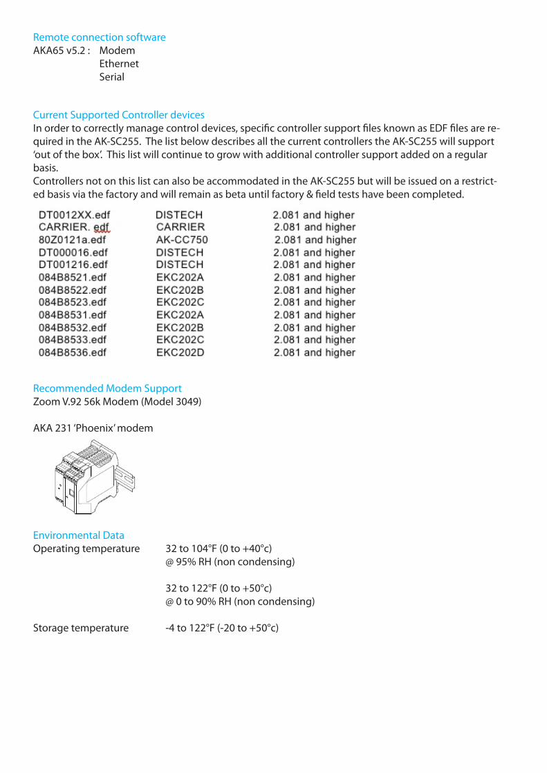
Current Supported Controller devicesIn order to correctly manage control devices, specific controller support files known as EDF files are re-quired in the AK-SC255. The list below describes all the current controllers the AK-SC255 will support ‘out of the box’. This list will continue to grow with additional controller support added on a regular basis.Controllers not on this list can also be accommodated in the AK-SC255 but will be issued on a restrict-ed basis via the factory and will remain as beta until factory & field tests have been completed.
Recommended Modem SupportZoom V.92 56k Modem (Model 3049)
AKA 231 ‘Phoenix’ modem
Environmental DataOperating temperature 32 to 104°F (0 to +40°c) @ 95% RH (non condensing)
32 to 122°F (0 to +50°c) @ 0 to 90% RH (non condensing)
Storage temperature -4 to 122°F (-20 to +50°c)
Remote connection softwareAKA65 v5.2 : Modem Ethernet Serial

5
Internal Component layout (Base board)
Mounting screw locations, general dimensions
10.16” (258 mm)
20.34” (516.34 mm)
1” (25 mm) Knockout
3/4” (19 mm) Knockout
8.00” (203.2 mm)
10.00” (254 mm)
CR2032
CPU Card
Serial Port
JP5 (battery jumper)
Reset buttonSystem address switch & JP3 / JP4
Mounting and Wiring The mounting location should be flat, dry and free from major vibrations. The AK-SC255 should be mounted at eye level, with consideration for the following approximate outline dimensions: Unit Width 10.5” (266 mm) Unit Height 12.5” (317 mm) Unit Depth 2.5” (63 mm) Mounting holes 8.0” (203.2 mm) Width Mounting holes 10.00” (254 mm) Height
To allow the door to fully open, ensure that there is an area at least 21” (533 mm) x 11” (280 mm) free, leaving room for conduit connections beneath the controller. Mount the controller using appropriate screws through the holes indicated at left, fastening the back of the controller enclosure securely to the flat surface chosen. Allow approx 3” (76 mm) for side access to local connection port (Danfoss cable part # 080Z0262)
Internal component layout With the controller door open, the two main sections of the AK-SC255 can be seen, Base board & Connector board.
Base boardMounted on the door frame is the ‘Base board’ with the main CPU card. The base board contains the following important components that need to be set for correct system operation:Battery (shipped in disabled position)Type CR2032 with (+) side facing toward the user.Engage battery circuit to ensure data is protected after power loss - set Jumper JP5 as follows. JP5
Host RS485 / Modbus NetworkThe AK-SC255 system utilizes a selectable RS485 / Mod bus port (located on Connector board). The unit comes factory set as Modbus communications. To enable RS485 Host network, jumpers JP3 & JP4 need to be set. Note that if Modbus is used, RS485 host is not available - set host to Ethernet in AK-SC255 software. JP3 JP4 JP3 & JP4 not connected = RS485 Host JP3 & JP4 connected = EKC Modbus
System address switch Rotary address switch to set AK-SC255 address Address 0 = Master (1-9 for Slave units)
System Reset button Use the CPU reset button to reset the AK-SC255

6
Internal component layout cont.Connector board The Connector board contains the main user connection ports needed for communications, relay output and power supply:
Ethernet Standard RJ45 Ethernet port, used for TCP/IP remote connection (LAN,WAN), SNMP network support & Host network. Use Ethernet as Host network if ‘Virtual Display’ functionality is required. RS485 Host network / ModbusSee table below for jumper settings
External ModemModem port used in conjunction with Modem Adapter kit 080Z2100Relay Rated at 30V d.c. 1Amp. Used for external alarm signal.
Lonworks® I/O NetworkThe I/O (Input-Output) network uses Echelon® Lon Talk® communications. Depending on AK-SC255 version, up to five I/O network cables can be connected to each AK-SC 255. When connecting “A” and “B” conductors, there is no polarity to observe for AK I/O modules. For more information about connecting I/O cables, and restrictions on their length and layout, consult the AK-SC255 Reference Manual. Attach a terminator to each set of unused I/O terminals. For Generic networks (EKC & AK controllers) it is recommended only to use one of the five ports available. Follow network wiring regulations for each of the different network types. For additional information on networks consult Danfoss document entitled ‘Data communication between ADAP-KOOL® Refrigeration Controls’ (RC8AC302)
EthernetExternal Modem
Port
Output relay RS485 /
Modbus
Lonworks® Communication Power Supply
Connector Board - User Connections
Lonworks® I/O Network (TP78)
AK-I/O Modules.. Generic Controller devices AK & EKC controllers
Terminator Terminator
AK-I/O Modules
Host / Modbus network options JP3 & JP4 Notes
RS485 Host OFF Used when combining AKC55 / 255 on host120 Ohm terminator to be on 1st & last unit
EKC Modbus ON (factory set)
Use for EKC Modbus controllers120 Ohm terminator to be on last controller onlyIf host network required use Ethernet
Ethernet Host N/A Use Ethernet port and connect to LANConfigure in ‘Communications’ section
Use the RS485 port either for RS485 Host or EKC Modbus communications. For RS485 Host communications, use 2 conductor shield cable. Up to 10 AK-SC255 controllers can be connected in a host network.

Functionality OverviewNetworksEKC controller IP network supportEKC / AK2 controller RS485 network supportEKC controller Modbus network supportAK Input / Output network
HVAC, AHU & Roof Top Unit controlCentral control or via RTC (roof top controller)
Lighting control30 lighting zones6 relays per zoneStandard or relative schedules8 schedules per zoneAuto override for burglar or fire alarmSwitch override with override box Photo Cell support & integration
Miscellaneous Points96 Misc Boolean Logic statements per AK-SC25564 Misc relay DO per AK-SC25548 Misc VO per AK-SC25510 Misc Conversion factors64 Misc sensor inputs & ON/OFF inputs - monitoring & alarm
Alarm routingModem / GSMTCP/IPRelay
Security8 Auth levels66 account codes
Screen TypeVGA high res colour
History Data points600 (per AK-SC255)
History Capacity10 minute samples on 120 points = 1 year

AK-SC255 'R' Fact Sheet (Version B1) DKRCE.PD.R1.B1.22 / 520H3579 ©Danfoss 07-2009
www.danfoss.us ADAP-KOOL® Refrigeration Control Systems is a trademark of Danfoss A/S, www.danfoss.com
Danfoss can accept no responsibility for possible errors in catalogs, brochures, or other printed material. Danfoss reserves the right to alter its products without notice. This also applies to products already on order provided that alterations can be made without subsequential changes being necessary in specifications already agreed. All trademarks in this material are property of the respective companies. Danfoss and the Danfoss logotype are trademarks of Danfoss A/S. All rights reserved.