AJS/Matchless Heavyweight Rear Hub, speedometer side ... · AJS/Matchless Heavyweight Rear Hub,...
15
AJS/Matchless Heavyweight Rear Hub, speedometer side assembly sequence Assembly of the Speedometer side of the rear hub of a '56 G-11. This was done with assistance of the Jampot Article from January 1998 titled "The Heavyweight Rear Hub" by C.G., edited by Chris Read as well as moral support from Mark Siebert and Pete "the cheap". Since I had difficulties in getting mine assembled correctly, I thought I'd take the time to make a web page out of it for others to share. This information is provided "as-is" and free of charge. The author assumes no liability for incorrect assembly. I believe this information is correct and complete to the best of my abilities. INCORRECT ASSEMBLY OF THESE PARTS CAN CAUSE THE REAR WHEEL TO LOCK-UP UNEXPECTEDLY, WHICH CAN CAUSE AN ACCIDENT - YOU HAVE BEEN WARNED. When in doubt, consult a professional mechanic.
Transcript of AJS/Matchless Heavyweight Rear Hub, speedometer side ... · AJS/Matchless Heavyweight Rear Hub,...

AJS/Matchless Heavyweight Rear Hub, speedometer side assembly sequence
Assembly of the Speedometer side of the rear hub of a '56 G-11. This was done with
assistance of the Jampot Article from January 1998 titled "The Heavyweight Rear
Hub" by C.G., edited by Chris Read as well as moral support from Mark Siebert and
Pete "the cheap". Since I had difficulties in getting mine assembled correctly, I
thought I'd take the time to make a web page out of it for others to share.
This information is provided "as-is" and free of charge. The author assumes no
liability for incorrect assembly. I believe this information is correct and complete
to the best of my abilities. INCORRECT ASSEMBLY OF THESE PARTS CAN
CAUSE THE REAR WHEEL TO LOCK-UP UNEXPECTEDLY, WHICH CAN
CAUSE AN ACCIDENT - YOU HAVE BEEN WARNED. When in doubt,
consult a professional mechanic.

Fig 1: All parts laid out in the proper sequence and proper orientation. Pay particular
attention to the orientation of the seal cup (2nd part from the left). The "wide" side
faces AWAY from the seal!
Matchless part numbers from left to right:
021608 - spacer, on rear wheel solid spindle, for oil seal
018094 - Cup, for rear hub bearing oil-seal
014387 - Oil-seal, for rear hub bearing
021585 - Ring, retaining, rear hub bearing oil seal (small)
021594 - Spacer on rear wheel spindle for speedo gear box
021583 - Ring, adjusting, for rear hub and 021584 - Nut, lock, for rear hub
bearing adjusting ring shown together

speedo drive
??? washer for speedo drive
021593 - Nut, locking, speedometer gearbox
Fig 2: The threaded axle the speedo drive attaches to as about to be inserted in the
retaining ring

Fig 3: End view of Fig 2. The threaded axle now rests in the seat

Fig 4: The thin washer (4th from left in 1st photo) now in place

Fig 5: Rubber (or felt) seal now in place. You must work this to fit within the opening
in the housing.

Fig 6: Cup in place (2nd part from left in photo #1). Again, note the orientation of the
cup. This orientation is critical!! The "narrow" side faces the oil seal.

Fig 7: Side view of Fig 6 - showing cup MUST BE FLUSH with housing!

Fig 8: Added spacer (left-most item from photo #1)
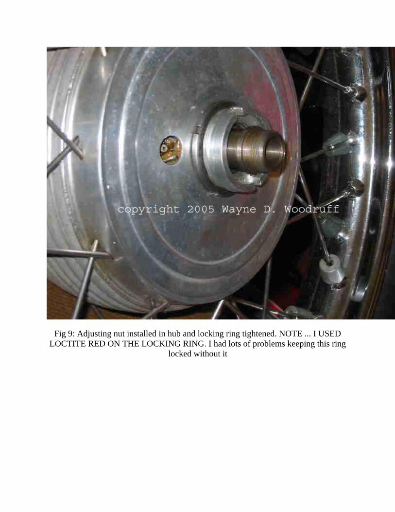
Fig 9: Adjusting nut installed in hub and locking ring tightened. NOTE ... I USED
LOCTITE RED ON THE LOCKING RING. I had lots of problems keeping this ring
locked without it
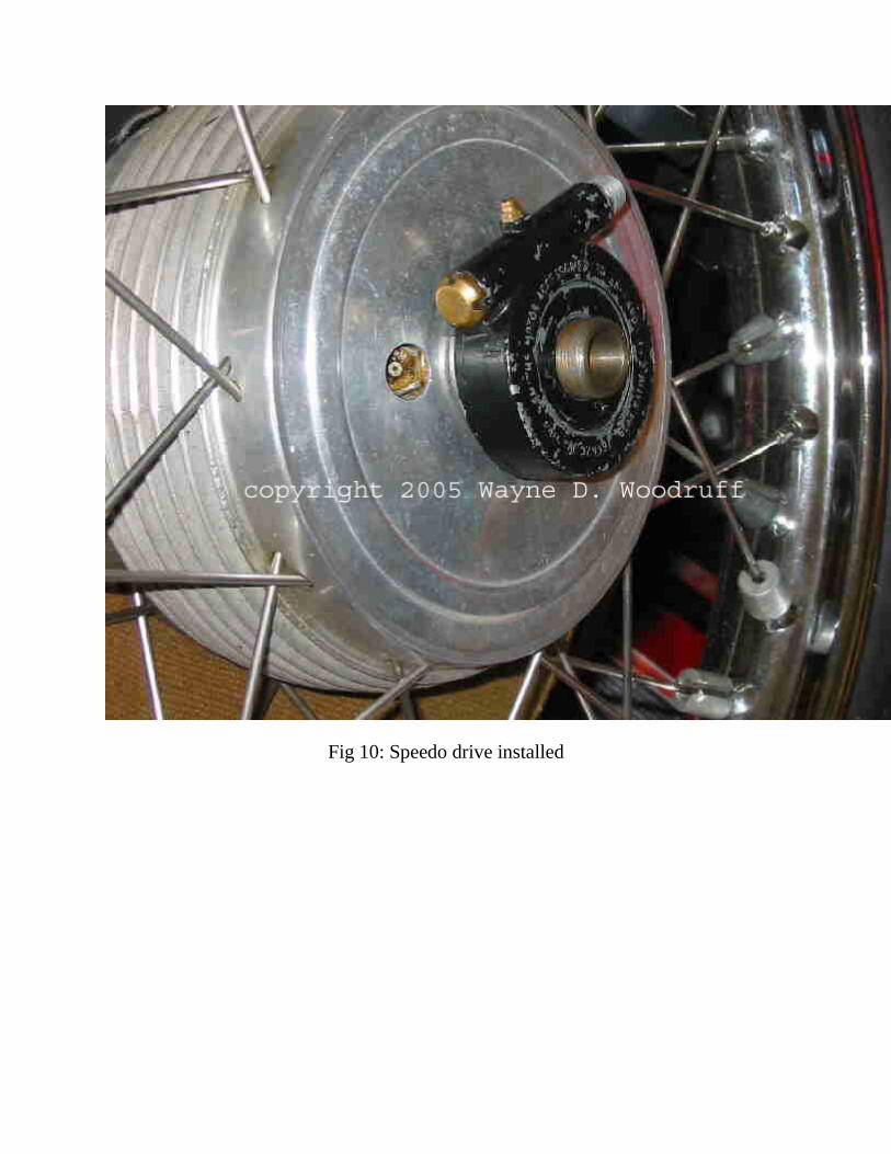
Fig 10: Speedo drive installed

Fig 11: Speedo drive installed with washer

Fig 12: Speedo drive installed with washer and nut - note orientation of nut! The final
tightening of the nut can be done with the wheel in place

Fig 13: Right side of rear wheel showing all installed components
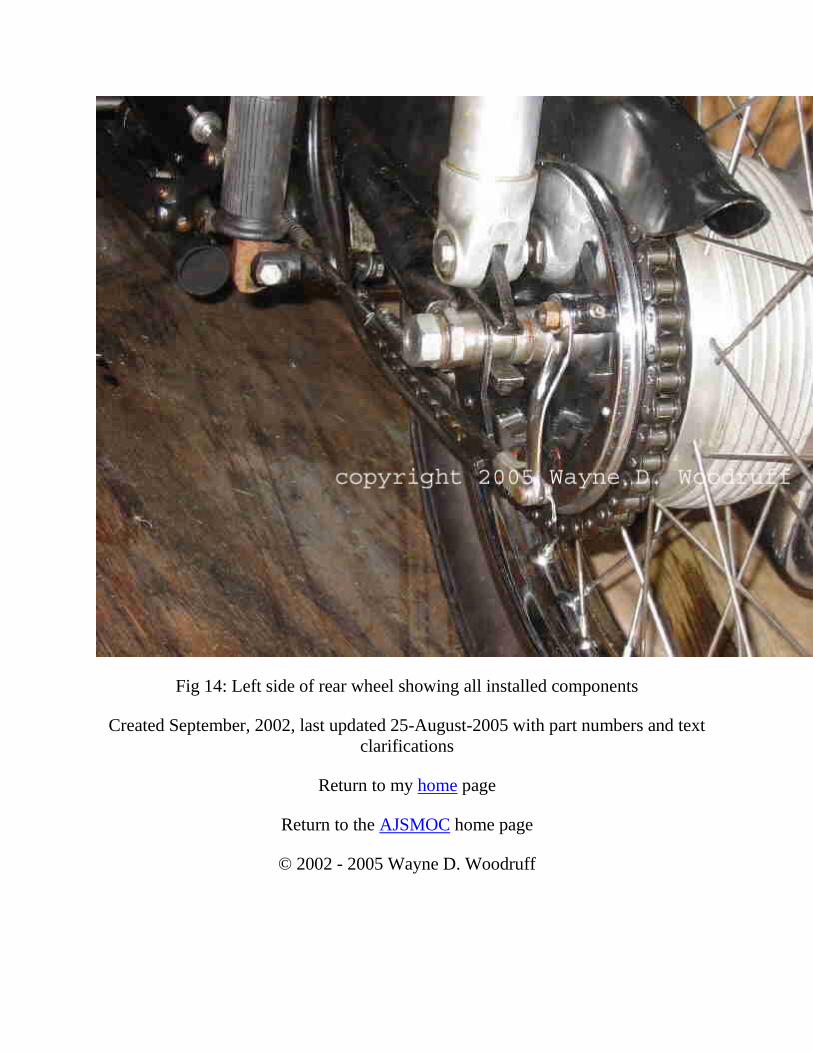
Fig 14: Left side of rear wheel showing all installed components
Created September, 2002, last updated 25-August-2005 with part numbers and text
clarifications
Return to my home page
Return to the AJSMOC home page
© 2002 - 2005 Wayne D. Woodruff