![· [Content_Types].xml bin application/vnd.openxmlformats-officedocument.spreadsheetml.printerSettings rels …](https://static.fdocuments.us/doc/165x107/5b1cf3297f8b9af05b8b7193/-contenttypesxml-bin-applicationvndopenxmlformats-officedocumentspreadsheetmlprintersettings.jpg)
Airport Visual Aids Research NEW... · Airport Visual Administration ... Computer Recorder Master...
103
Federal Aviation Administration Federal Aviation Administration Airport Visual Aids Research ICAO Workshop on Air Navigation Visual Aids New Technologies May 7-11, 2012 ICAO South American Regional Office Lima, Peru Presented by Alvin Logan FAA AAS-100
Transcript of Airport Visual Aids Research NEW... · Airport Visual Administration ... Computer Recorder Master...
Federal Aviation Administration Federal Aviation Administration Airport Visual
Aids Research
ICAO Workshop on Air
Navigation Visual Aids
New Technologies
May 7-11, 2012
ICAO South American
Regional Office
Lima, Peru
Presented by Alvin Logan
FAA AAS-100

Federal Aviation Administration
Outline
• Engineering Brief Updates
• Final Approach Runway Occupancy Signal
(FAROS)
• Enhanced Flight Vision System
• Night Vision Goggles
• Conspicuity of LEDs in Fog

Federal Aviation Administration
Outline
• Runway Status Lights (RWSL)
• RWSL THL/ALSF-II Assessment
• LED Evolution
• LED Research
• Delta Airlines Incident on Taxiway

Federal Aviation Administration
Engineering Brief Updates

Federal Aviation Administration
• EB-84 for ALCMS Security Draft
– Design and use of virtual private network (VPN)
systems to enable secure off-site remote
maintenance and monitoring of airport lighting
control monitoring systems (ALCMS).
Draft Engineering Briefs
Secure access to critical systems for remote support personnel

Federal Aviation Administration
• EB for Night Vision Imagery System – Provides information and guidance for the use of
night vision systems on board both rotary and fixed wing aircraft. In addition, a prototype LED obstruction light fixture with built-in NVIS compatibility is proposed.
Draft Engineering Briefs

Federal Aviation Administration
• EB-89 – Guidance for Taxiway Naming Convention
– This Engineering Brief provides clarification for taxiway
naming convention standards contained in FAA Advisory
Circular (AC) 150/5340-18F, Standards for Airport Sign
Systems.
• EB-XX – FAROS
– Design guidance for implementation of a direct warning
system (based on LOOPs sensor) to airborne flight
crews of runway occupancy status.
Draft Engineering Briefs

Federal Aviation Administration
FAROS

Federal Aviation Administration
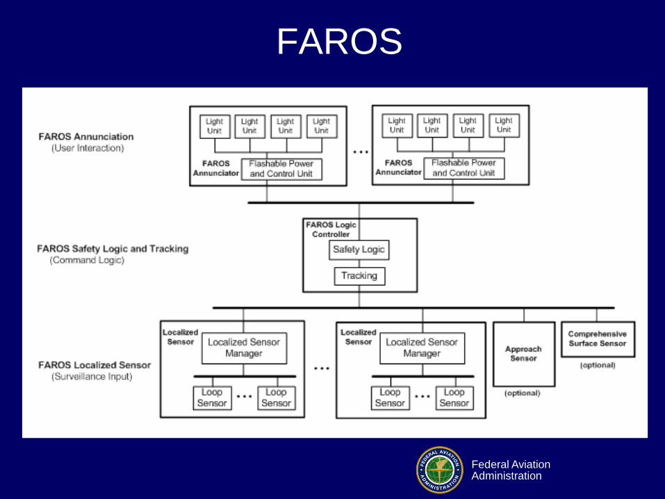
FAROS
• Developed by ANC-G5, Office of Advanced
Concepts & Technology Development
• EB for FAROS/eFAROS – Design guidance for implementation of a direct
warning system (based on LOOPs sensor) to airborne flight crews of runway occupancy status.
• FAROS Engineering Brief has been circulated
to FAA Regions for comment to make a
determination of feasibility, practicality of
usage.
Federal Aviation Administration
FAROS

Federal Aviation Administration
FAROS Operational Concept
Federal Aviation Administration
EFVS

Federal Aviation Administration
Enhanced Flight Vision Systems (EFVS)
14 CFR 1.1 defines EFVS as –
“Enhanced flight vision system (EFVS) means an
electronic means to provide a display of the
forward external scene topography (the natural
or manmade features of a place or region
especially in a way to show their relative
positions and elevation) through the use of
imaging sensors, such as a forward looking
infrared, millimeter wave radiometry, millimeter
wave radar, low light level image intensifying. “
Federal Aviation Administration
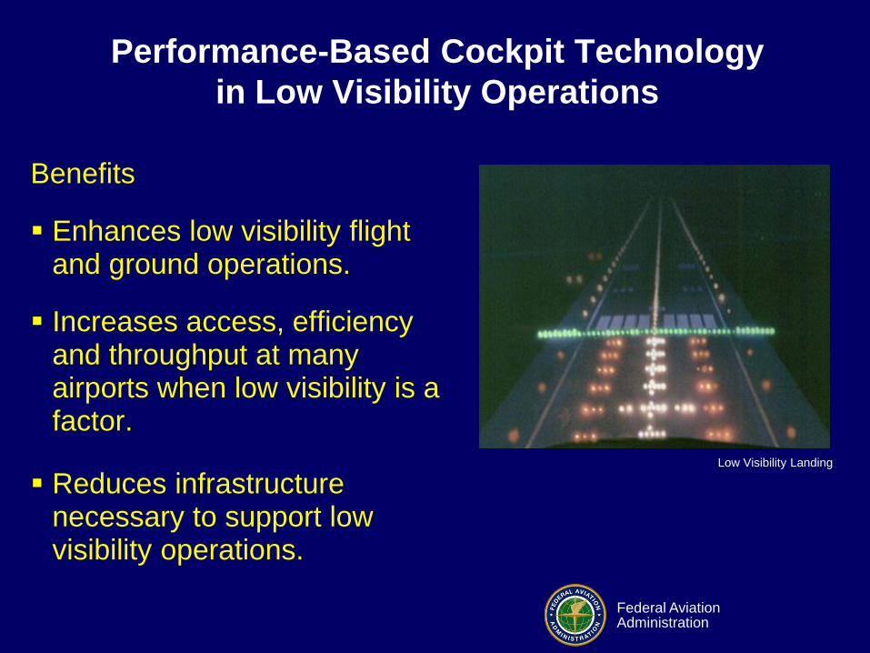
Performance-Based Cockpit Technology
in Low Visibility Operations
Benefits
Enhances low visibility flight and ground operations.
Increases access, efficiency and throughput at many airports when low visibility is a factor.
Reduces infrastructure necessary to support low visibility operations.
Low Visibility Landing

Federal Aviation Administration
• Provides flight guidance
on a HUD
HUD + Sensor Imagery = EFVS
• Provides a real time display of the
outside world in low visibility
conditions through the use of
imaging sensors (forward looking
infrared, millimeter wave, low-light
level intensifying, etc.)
Performance-Based Cockpit Technology
in Low Visibility Operations

Federal Aviation Administration
Operational Concept for EFVS
Instrument Segment
CAT I DA or
MDA 100’ HAT
Illustration Courtesy of Mitre CAASD
Permitted on straight-in landing instrument approach procedures other than Category II or Category III (i.e., nonprecision, Category I precision, and APV).
Provides another means of operating in the visual segment – EFVS in lieu of natural vision.
EFVS enables descent below DA or MDA to 100 feet above TDZE
provided certain requirements are met --
Enhanced flight visibility equal to/greater than that specified in the IAP.
Required visual references must be distinctly visible/identifiable.
All other requirements of § 91.175 (l) must be met.
Requires natural vision to be used to identify required visual
references for descent below 100 feet above TDZE. EFVS Segment
Natural Vision Segment

Federal Aviation Administration
Ongoing Actions for EFVS
• Attend and participate in SAE G-20
committee meetings for EFVS.
• Participate in EFVS MALSR/IR program
reviews within the Navigation Services
Group.
• Participate in EFVS NPRM (Newly
Published Rule Making) Document
Preparation. – EFVS NPRM to be signed May 16, 2012

Federal Aviation Administration
Night Vision Goggles

Federal Aviation Administration
MIL-STD-3009
• LIGHTING, AIRCRAFT, NIGHT VISION IMAGING SYSTEM (NVIS) COMPATIBLE
• NVGs derived from military requirements.
• Provides interface requirements and testing methodology to ensure compatible and standardized aircraft interior lighting for NVIS compatibility.

Federal Aviation Administration
Night Vision Goggles
• Claim: LEDs cannot be seen with Night
Vision Goggles!
• Visible light detected is independent of
the lighting technology.
– It is based on the spectrum the NVG
technology uses.
• NVGs have either Type A or B filters
which changes the spectrum sensed.

Federal Aviation Administration
Night Vision Goggles
• Commonly used Gen 3 NVGs sensitivity
range is from approx. 450nm to 920nm.
• Commonly produced LEDs are from
460nm for Blue to 645nm for Red.
• NVG Gen3 without filters will respond to
Green, Yellow, and Red LEDs.

Federal Aviation Administration
Night Vision Goggles
• NVGs’ spectral response in
the range of approximately
600 to 900 nanometers in
wavelength.

Federal Aviation Administration
Visible Spectrum
Vacuum wavelength
(nm)Frequency (10
12Hz) Brain color response
730-622 410-482 RED
622-597 482-503 ORANGE
597-577 503-520 YELLOW
577-492 520-610 GREEN
492-455 610-659 BLUE
455-370 659-810 VIOLET
VISIBLE SPECTRUM OF LIGHT

Federal Aviation Administration
Incandescent Light Output Spectrum
Federal Aviation Administration
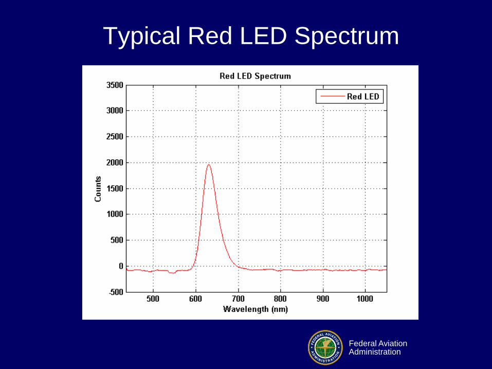
Typical Red LED Spectrum

Federal Aviation Administration
Night Vision Goggles
• Class A filters respond at wavelengths
longer than 625nm and Class B at
665nm.
• NVGs can detect red LEDs using Class A
filters.
• NVGs cannot detect any LEDs using
Class B filters. Some incandescent lights
may be seen.
Federal Aviation Administration
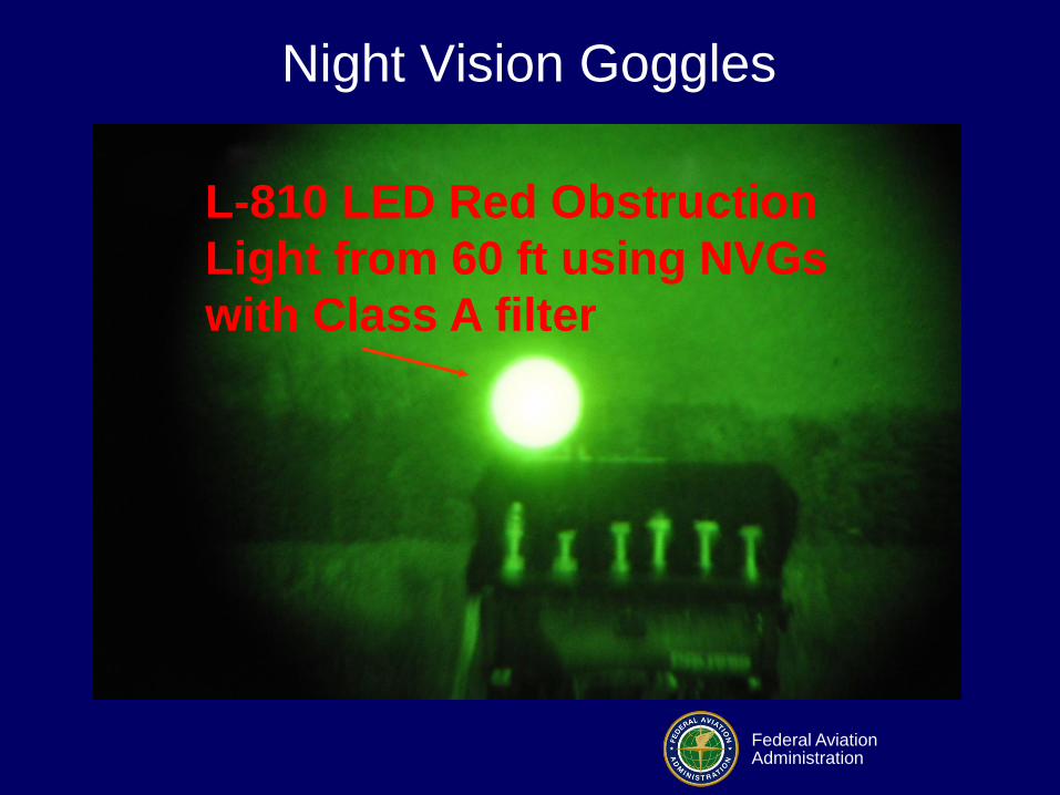
Night Vision Goggles
L-810 LED Red Obstruction
Light from 60 ft using NVGs
with Class A filter

Federal Aviation Administration
Conspicuity of
Incandescent and LEDs in Fog

Federal Aviation Administration
Are LEDs Visible in Fog?
Federal Aviation Administration
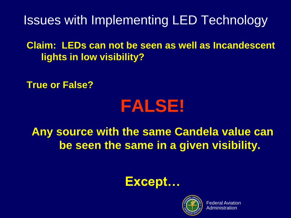
Issues with Implementing LED Technology
Claim: LEDs can not be seen as well as Incandescent
lights in low visibility?
True or False?
FALSE!
Any source with the same Candela value can
be seen the same in a given visibility.
Except…

Federal Aviation Administration
Perceived Brightness
• There is a quantifiable “Brightness/Luminance” (B/L)
conversion factor with LEDs.
• Conversion to Incandescent:
– Blue B/L = 1.4
– White B/L = 1.6
– Green B/L = 1.4
• However, light scattered by Fog can
desaturate LED signal colors reducing or
eliminating the brightness advantage.

Federal Aviation Administration
Issues with Implementing LED Technology
Incandescent & LED Lights at same intensity
observed from 100 feet.
Observers noted that the Incandescent lost
the GREEN appearance early.

Federal Aviation Administration
Issues with Implementing LED Technology
Incandescent & LED Lights at same intensity
observed from 100 feet.
LED light still has GREEN appearance.

Federal Aviation Administration
Runway Status Lights
Federal Aviation Administration
RWSL
• Purpose
– Reduce frequency and severity of runway
incursions
– Prevent runway accidents
• RWSL increases situational awareness
– RELs provide a direct indication to pilots
when it is unsafe to cross or enter a runway
– THLs provide a direct indication to pilots
when it is unsafe to depart from a runway

Federal Aviation Administration
RWSL System Architecture
ASDE-X
Data
Distribution
LEGEND Existing NAS Hardware
New RWSL Hardware
RWSL
Processor
In-pavement
Light Fixtures
Cab Control
Panel
Airfield Air Traffic Control Tower (ATCT)
ATCT Equipment Room
Airfield Shelter
Maintenance
Terminal
Remote
Maintenance
Terminal
Constant
Current
Regulator (CCR)
Light
Computer
Recorder
Master Light
Controller (MLC) Individual Light
Controller (ILC)
Isolation
Transformer

Federal Aviation Administration
RWSL RELs and THLs
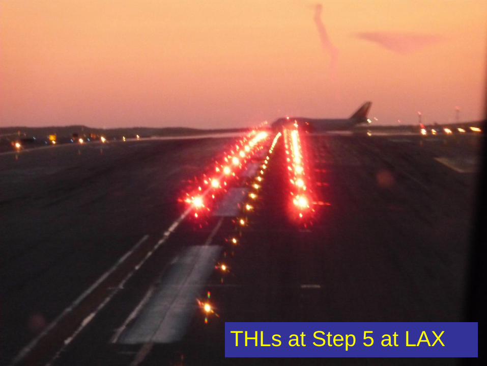
Runway Status Lights integrates airport lighting equipment with approach and surface surveillance systems to provide a visual signal to pilots indicating that it is unsafe to enter/cross or begin takeoff on runway
Runway Entrance Lights (REL)
provide signal to aircraft crossing
runway from intersecting taxiway
Takeoff Hold Lights (THL) provide signal to aircraft in position for takeoff

Federal Aviation Administration
RELs at San Diego
Federal Aviation Administration
THLs at Step 5 at LAX

Federal Aviation Administration
Field
Lighting
Shelter
(Up to 4 Circuits)
Field
Lighting
Shelter
RWSL Processor
Lighting Computer
(LC) Processor
Takeoff
Hold Lights
Runway Entrance Lights
General Overview of
Equipment
Federal Aviation Administration
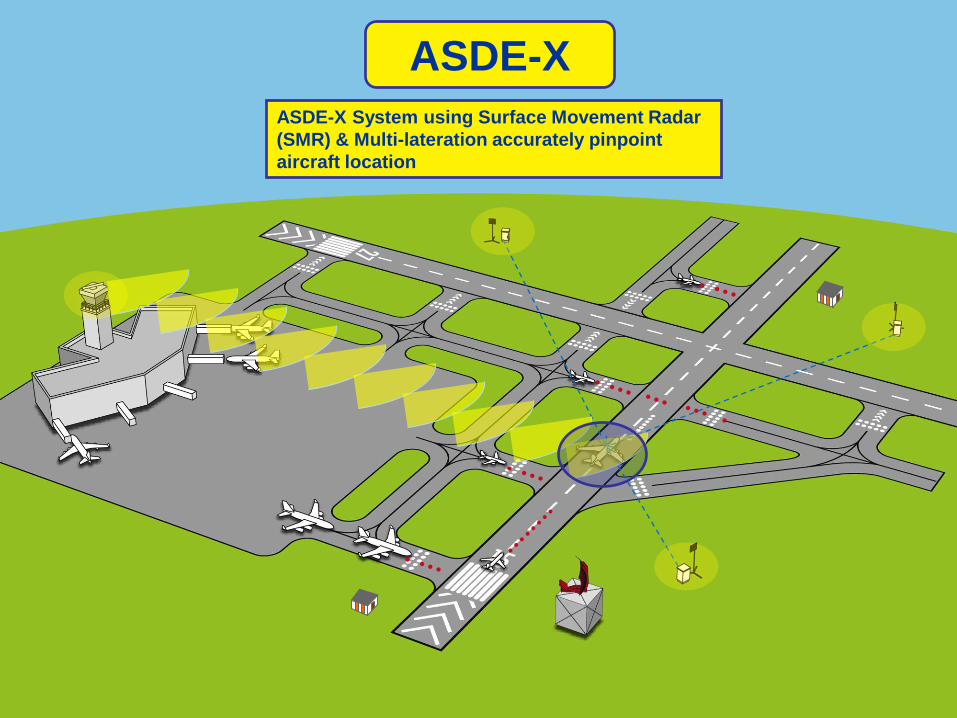
ASDE-X
ASDE-X System using Surface Movement Radar
(SMR) & Multi-lateration accurately pinpoint
aircraft location

Federal Aviation Administration
Field Lighting
System (FLS)
Runway Entry Lights (RELs) & Take-Off
Hold Lights (THLs) are automatically
controlled
Lights turn On when aircraft are
occupying the runways
Lights are Off otherwise

Federal Aviation Administration
Concurrent with RWSL the ASDE-X
System notifies Air Traffic Controllers
if an aircraft or vehicle enters an
active runway with an audible Safety
Alert

Federal Aviation Administration
18
R
Runway Entrance Light
REL L-852S
Takeoff Hold Light
THL L-850T
FAA RWSL In-pavement LED
• FAA Certified
• 12”, Style III (<1/4” above pavement)
• Instant turn-on time, even in lower
intensity steps.
• Fixtures are electronically monitored
to detect individual fixture failure
locations
• Available with optional heater THL L-850T
REL L-852S
RWSL

Federal Aviation Administration
RWSL SAFO

Federal Aviation Administration
RWSL Production System Airport List ID Region Airport
MCO ASO Orlando International Airport
IAH ASW George Bush Intercontinental Airport
PHX ASW Phoenix Sky Harbor International Airport
SEA ANM Seattle-Tacoma International Airport
IAD AEA Washington Dulles International Airport
CLT ASO Charlotte Douglas International Airport
FLL ASO Ft. Lauderdale/Hollywood Airport
MSP AGL Minneapolis-St. Paul International Airport
LAS AWP Las Vegas McCarran International Airport
ORD AGL Chicago O'Hare International Airport
LGA AEA LaGuardia Airport
JFK AEA John F. Kennedy International Airport
DTW AGL Detroit Metro Wayne County Airport
EWR AEA Newark International Airport
PHL AEA Philadelphia International Airport
DFW ASW Dallas/Ft. Worth International Airport
LAX AWP Los Angeles International Airport
SAN AWP San Diego International Airport
BWI AEA Baltimore-Washington International Airport
BOS ANE Boston Logan International Airport
ATL ASO Hartsfield-Jackson Atlanta International Airport
DEN ANM Denver International Airport
SFO AWP San Francisco International Airport
PSFOklahoma City - NAS Engineering Program Support
Facility (PSF)
ILS Oklahoma City - FAA Logistics Center/Depot
ACA Oklahoma City - FAA Academy

Federal Aviation Administration
RWSL Program Office
Claude Jones Program Manager 202-385-8407
Barbara Kratz Project Lead 202-385-8645
Mike Weiler Implementation Lead 202-385-8767
Bashar Halabi
Engineering lead 202-385-8695
Cynthia Schauland Integrated Logistics
Support Lead
202-603-6796
Jim Hayes
Dave Reynolds
Contracts 202-385-8644
202-385-8658

Federal Aviation Administration
RWSL THLs and ALSF-II Evaluation

Federal Aviation Administration
BOS Logan
• Synopsis:
The incident occurred on 6/24/2011 at
1217UTC. DAL561 advised he was seeing
red lights while in position on runway 4R.
The crew refused to takeoff, did not roll and
an arrival to 4R had to go around.

Federal Aviation Administration
Discussion:
• There was a recent pilot RWSL survey at BOS.
• There are no RWSL THLs on BOS 4R
• Pilot's comments regarding the acquisition red lights on that runway was puzzling.
• Weather at BOS that day was low IFR
• Aircraft arriving to 4R on a CAT II ILS approach.
BOS Logan

Federal Aviation Administration
Completed Testing in MITRE CAASD Simulator: • Test for Pilot Confusion between THLs and ALSF-2:
– It exists!
• MITRE Outcome Briefing to FAA
THLs
ALSF-2
Runway Safety Assessment Response to
Takeoff Hold Lights

Federal Aviation Administration
• Runway Safety Assessment (RSA) for
Pilot Response to Takeoff Hold Lights
underway.
• Mitre, ANC-G5, Office of Advanced
Concepts & Technology Development,
AAS-100, Airport Engineering Division
and Flight Standards.
Runway Safety Assessment Response to
Takeoff Hold Lights
Federal Aviation Administration
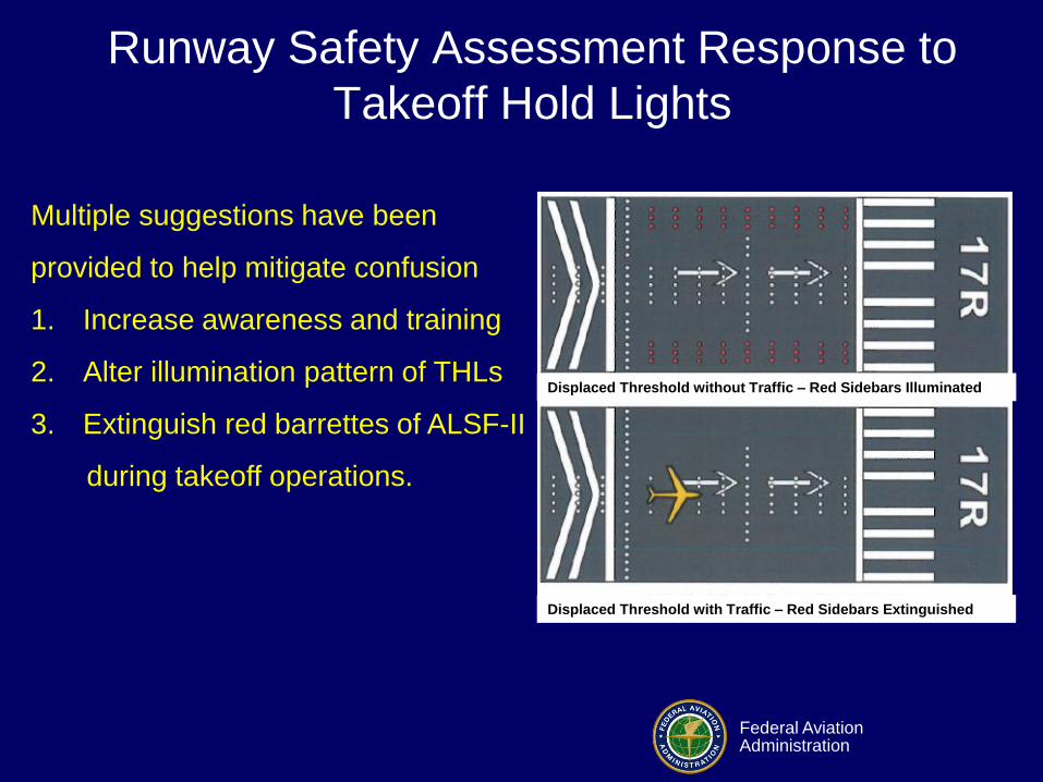
Displaced Threshold with Traffic – Red Sidebars Extinguished
Displaced Threshold without Traffic – Red Sidebars Illuminated
Multiple suggestions have been
provided to help mitigate confusion
1. Increase awareness and training
2. Alter illumination pattern of THLs
3. Extinguish red barrettes of ALSF-II
during takeoff operations.
Runway Safety Assessment Response to
Takeoff Hold Lights

Federal Aviation Administration
Light Emitting Diodes

Federal Aviation Administration
LED Composition
• Aluminum gallium indium phosphide
(AlGaInP)
– Produces red, orange and yellow LEDs
• Indium gallium nitride (InGaN)
– Produces red, green and blue LEDs
• Mixture of red, green and blue LEDs
produces white LEDs OR blue LED +
phosphor material.

Federal Aviation Administration
LED Evolution

Federal Aviation Administration
LED Deployment
• FAA Certified Lighting Manufacturers have
sold and installed at least 1 million LED
Lighting Applications
Federal Aviation Administration
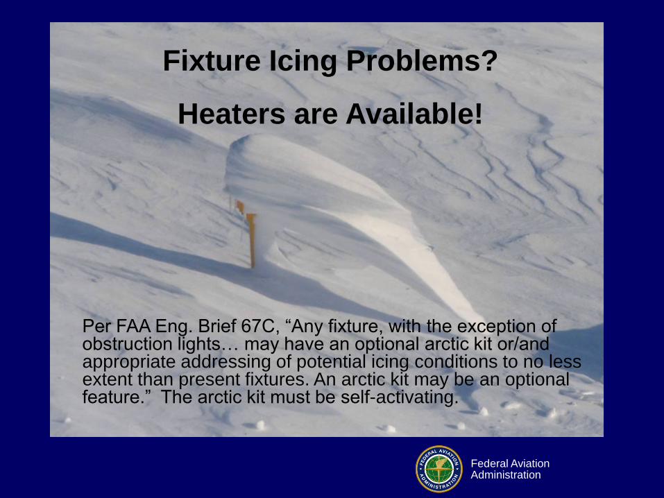
Fixture Icing Problems?
Heaters are Available!
Per FAA Eng. Brief 67C, “Any fixture, with the exception of obstruction lights… may have an optional arctic kit or/and appropriate addressing of potential icing conditions to no less extent than present fixtures. An arctic kit may be an optional feature.” The arctic kit must be self-activating.

Federal Aviation Administration
LED Research

Federal Aviation Administration
Elevated Runway
Guard Lights
Evaluation
Federal Aviation Administration
Elevated Runway Guard Light
• Most major airports implement Runway
Guard Lights.
– As a supplemental device used in
conjunction with hold position markings and
signs.
– Due to operations under low visibility
conditions
– Hard-wired Runway Guard Lights
• Require Infrastructure
– What about General Aviation (GA) airports?

Federal Aviation Administration
• General Aviation Airports
– “Hot Spots”
• Pilots and drivers crossing the active
runway unauthorized creating a runway
incursion.
– Problem with implementing Runway
Guard lights is cost.
– New Technology
Elevated Runway Guard Light

Federal Aviation Administration
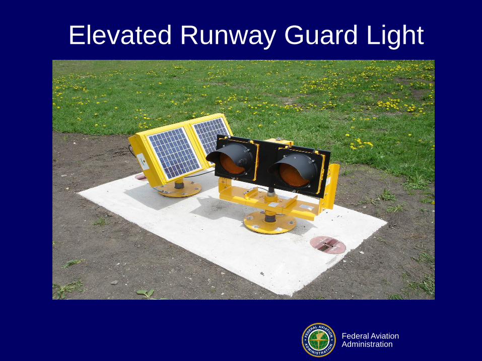
– A prototype Solar-powered light emitting
diode (LED) runway guard light unit was
developed.
• FAA’s L-804 Lamp Housing
• Solar Panel
– Initial evaluations were implemented at the
Tech Center
• Different climate conditions
– Field Testing
• Dupage Airport, Chicago Installed May 2008
• Provo Airport, Provo, UT Installed May 2008
Elevated Runway Guard Light
Federal Aviation Administration
Elevated Runway Guard Light
Federal Aviation Administration
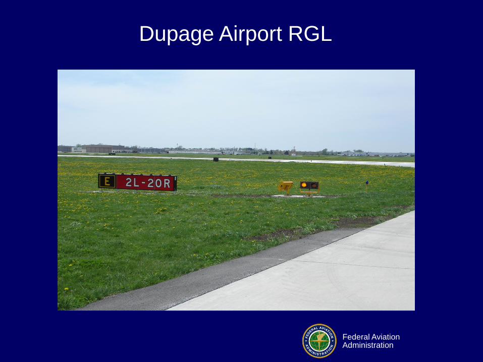
Dupage Airport RGL

Federal Aviation Administration
Provo Airport RGL

Federal Aviation Administration
Elevated Runway Guard Light
• Currently
– Collecting pilot data (Surveys)
– Monitoring systems at both airports
• Evaluation continuing

Federal Aviation Administration
Minimum Intensity for Incandescent
Runway Guard Lights (RGL)
• Prior to 1996, the minimum luminous intensity
requirement was 600 cd
– Increased to 3000 cd based on results from 1996
study
• Flash rate was also increased from 30 cycles
per minute to 45-50 cycles per minute
– Study looked at 30, 48 & 60 flashes per minute
Federal Aviation Administration
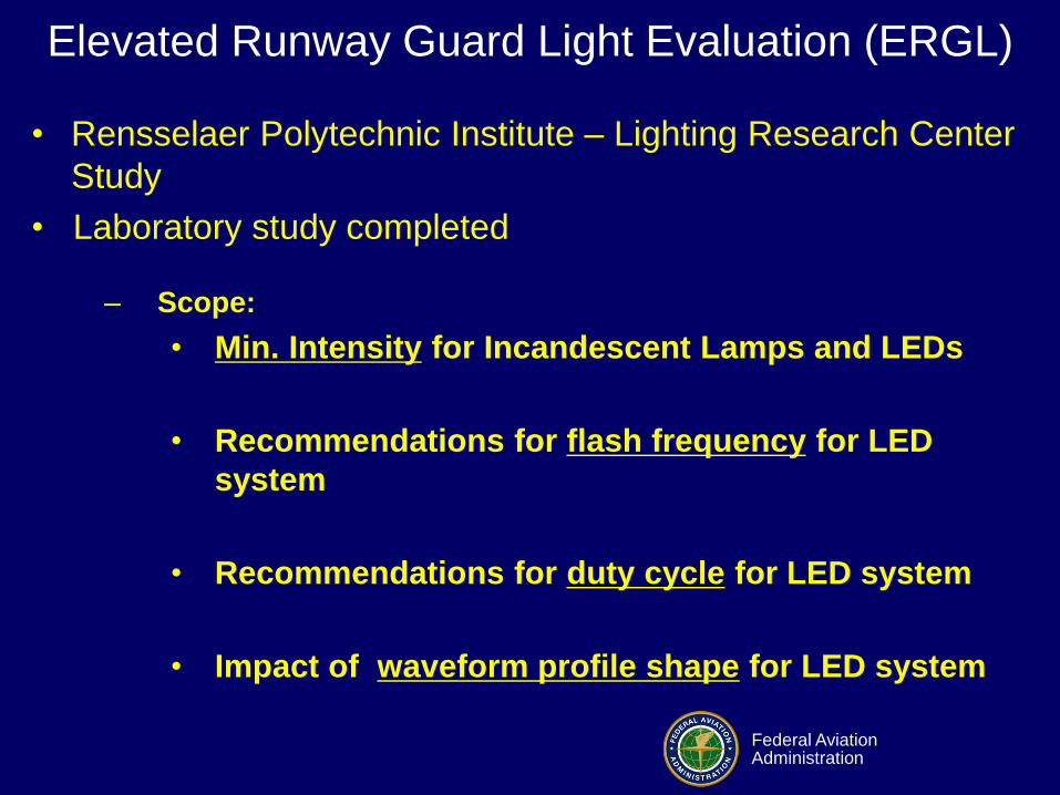
Elevated Runway Guard Light Evaluation (ERGL)
• Rensselaer Polytechnic Institute – Lighting Research Center
Study
• Laboratory study completed
– Scope:
• Min. Intensity for Incandescent Lamps and LEDs
• Recommendations for flash frequency for LED
system
• Recommendations for duty cycle for LED system
• Impact of waveform profile shape for LED system

Federal Aviation Administration
Experimental Outline
• Phase 1 – Identify minimum luminous intensity for incandescent RGL across all ambient conditions
• Phase 2 – Determine the optimum level for each variable (frequency, duty cycle, waveform, ambient condition)
• Phase 3 – Apply decreasing levels of intensity for each promising combination of variables at each ambient condition

Federal Aviation Administration
Test Apparatus

Federal Aviation Administration
Test Apparatus
Foggy Day Setup
Subject View

Federal Aviation Administration
Subject Characterization
• Ten subjects for each trial
• Subject pool was fairly consistent across all trials
• Age range: 22 – 62
• Visual acuity (binocular) Avg: 20/25 Minimum: 20/50
• All subjects demonstrated normal color vision
n=8 n=2

Federal Aviation Administration
Technology-Neutral Specification
• Results indicate that square waveform is more conspicuous than triangle or incandescent waveform
• Intensity required will be based on combination of other factors (e.g., duty cycle and frequency combination)
• LEDs can be “tuned” to offer these effective combinations (and energy savings) but other technologies may evolve to offer the same effectiveness

Federal Aviation Administration
Findings
• It is not recommended that the current
incandescent-based ERGL specification
be changed.
• LED ERGL intensities could be reduced.

Federal Aviation Administration
Recommendations
• These values can be obtained by a combination
of selecting a square wave signal, flash rate, and
on-time percentage.
• The best flash rates & on-time percentages
were: 1.25 Hz @ 70% or 2.50 Hz @ 30%
LED ERGL
Step
Current Standard Recommended
Value
Step 3 (100%) 3000 cd 451-1128 cd
Step 1 (10%) 300 cd 68-113 cd

Federal Aviation Administration
Moving Forward
• Field study are being conducted to validate
results before final recommendations are
made.

Federal Aviation Administration
LEDs and Color Vision Deficiency
Federal Aviation Administration
LED Applications Issues
Does the “narrow spectral band” of LEDS impact
pilots with certain types of color deficient vision?
CIVIL AEROSPACE MEDICAL INSTITUTE (CAMI) and Airport
Safety Technology R&D (AJP-6311) completed March 2010 an
evaluation on this issue sponsored by the Lighting Systems
Office, AJW-46 and Office of Airport Safety and Standards, AAS-1.

Federal Aviation Administration
LEDs and Color Deficiency Issue
• Approximately 8% of males and 0.5% of females in
the population have congenital red-green color-
deficient vision.
• They have reduced ability to discriminate redness-
greenness throughout the full gamut of colors.
• The problem includes the red, orange, yellow, and
yellow-green parts of the visible spectrum.
• Red and green are not uniformly replaced by grey.
For some people with color-vision deficiency,
colors like beige and yellow replace red and green.

Federal Aviation Administration
LED Applications Issues
• The three main varieties of color-vision deficiency
1. Protan - cannot distinguish reds and greens; reds
appear dark and less bright than other colors.
2. Deutan - like protans, cannot distinguish reds and
greens. though, there is no brightness deficiency.
3. Tritan - blues and greens are confused (less
common).
• Majority of color deficients are Deutans.
• Preliminary results show LEDs may actually help
Deutans.

Federal Aviation Administration
LED Color Boundaries

Federal Aviation Administration
• Aviation White LED Chromaticity Boundaries
– Yellow boundary: x = 0.440
– Blue boundary: x = 0.320
– Green boundary: y = 0.150 + 0.643x
– Purple boundary: y = 0.050 + 0.757x
• Boundary Intersection Points for Aviation White:
– x = 0.320, y = 0.356
– x = 0.440, y = 0.433
– x = 0.440, y = 0.383
– x = 0.320, y = 0.292
LED Color Boundaries

Federal Aviation Administration
LED Color Boundaries
• Green (ICAO Modified)
• Blue (ICAO)
• Yellow (CIE S 0004/E2001)
• Restricted Red (CIE S 0004/E-2001
restricted region)

Federal Aviation Administration
RCL Evaluation

Federal Aviation Administration
Runway Centerline Light Evaluation
• ICAO initiative proposed to evaluate and
change current standard.
– Red means stop!
• Evaluate changing alternating red/white runway
centerline lights to alternating yellow/white.
• Also includes evaluating changes to last 1000
feet of red runway centerline to yellow.

Federal Aviation Administration
Runway Centerline Lights Evaluation
Present
Future?

Federal Aviation Administration
Delta Airlines Taxiway M
Landing at ATL

Federal Aviation Administration
On Monday, October 19, 2009, at
6:05 a.m. EDT, a Boeing B767
operating as Delta Air Lines
flight 60 (DL 60) from Rio de
Janeiro, Brazil, to Atlanta,
Georgia, landed on taxiway M at
(ATL) after being cleared to land
on runway 27R. No injuries to
any of the 182 passengers or 11
crewmembers were reported.
Delta Airlines Taxiway M Landing - ATL
First Assigned
Runway (26R)
Taxiway M
(Incident
Landing
Area)
Original Briefed
Landing Runway
(27L)
Second Assigned
Landing Runway
(27L)
Third Assigned
(Sidestep) Landing
Runway (27R)

Federal Aviation Administration
• The runway lights for 27R were illuminated.
• Localizer and approach lights for the runway
were not turned on.
• Taxiway M was active but was clear of aircraft
and ground vehicles at the time the aircraft
landed.
• The wind was calm with 10 miles visibility.
• Night VFR conditions prevailed.
Specifics of that Morning - ATL

Federal Aviation Administration
Flight Team Investigation

Federal Aviation Administration
• Runway 27R lights were set on step 1 intensity
• PAPIs for runway 27L and runway 27R were
easily discernable however runway 27R was not
easily identified.
• Runway 27R edge lights were very dim in
comparison to its neighboring taxiway.
• Taxiway M lighting appeared markedly brighter
than runway 27R
– Lights are hardwired on step 3 intensity (100%)
Delta Airlines Taxiway M Landing - ATL

Federal Aviation Administration
ATL Runway 27L Runway Lights on Step 1

Federal Aviation Administration
• Numerous signs that marked taxiway M
connector taxiway stubs between runway 27R
and taxiway L appeared as white edge lighting
and mimicked the appearance of a runway.
• LED taxiway centerline lighting lead in lights
were bright and could be seen on the taxiway
– The remaining length of incandescent lights were
not as easily identified as were the LED lights
Delta Airlines Taxiway M Landing - ATL

Federal Aviation Administration
Alternating Yellow/Green taxiway
centerline lights back to ILS…
parallel with runway
LEDs
Incandescent
Signs confused as runway
edge lights during flight test

Federal Aviation Administration
• The taxiway M lighting was dominant and
appeared to be white.
• The illusion that the M taxiway was a runway
was further supported with the PAPI position to
its left.
– The PAPI is positioned to the right of runway 27R.
• The wing threshold lights for runway 27R were
not easily discernable
– Perhaps due to the light pollution in the area
– More dominant lighting on the taxiway
Delta Airlines Taxiway M Landing - ATL

Federal Aviation Administration
• Runway lights were observed at settings step 1, 2 and step 3
• Step 1 was very dim in comparison to its parallel taxiway, taxiway M.
• Step 2 did not make much difference and was not effective in differentiating the runway from the taxiway.
• Step 3 was very effective and adding the approach lighting to the equation made identification likely.
Delta Airlines Taxiway M Landing - ATL

Federal Aviation Administration
PAPI on right side of runway,
therefore on left side of parallel taxiway

Federal Aviation Administration
Measured Chromaticity
• Measured chromaticity
for centerline and edge
lighting on Taxiway M
were within standard.

Federal Aviation Administration
• On the date of the incident, the Delta crew
misidentified Taxiway M as runway 27R
– The approach lights and localizer were not activated.
• Consensus of the flight team was that when
runway 27R is offered or used for arrival
aircraft,
– Runway edge lights should be set to no lower than
step 3
– Approach lights should be activated to provide
adequate visual cues to the flight crews for
identifying the runway surface.
Conclusions of Taxiway M Landing - ATL

Federal Aviation Administration

Federal Aviation Administration
• NVIS-Class-B-modified cockpit lighting as
viewed through Class-A objective lens ANVIS-9
NVGs
• NVIS-Class-B-modified cockpit lighting as
viewed through Class-B objective lens ANVIS-9
NVGs. Class-B objective lens filters all light
below 665 nanometers.
• Allows the additional use of some red lighting,
primarily to allow for three-color multi-function
displays
Federal Aviation Administration
• One of the most common compatibility issues
occurs when trying to align a “Class A” or “Class
B” objective lens on the night vision device with
the lighting configuration of the aircraft.
• Due to the brightness and spectral characteristics
of conventional aircraft lighting and the sensitivity
of the NVGs’ spectral response in the range of
approximately 600 to 900 nanometers in
wavelength, the aircraft lighting must be modified
for the two to efficiently work together.