Airplane Performance Analysis through CFD Results ...
5
150 Airplane Performance Analysis through CFD Results: Assessment of a NACA 64A212 Wing-body Combination JI Abeygoonewardena 1 , RMPS Bandara 2 12 General Sir John Kotelawala Defence University, Sri Lanka 1 [email protected], 2 [email protected] Abstract - A comprehensive understanding of fluid and flight dynamics of an aircraft cannot be understated from both an engineering and aircraft handling perspective. In this context, availability of such descriptive information, especially in the case of trainer aircraft, will deliver profitable results for both students and trainers. Detailed information regarding the aerodynamic behaviour of the wing is not disclosed by the aircraft manufacturer to relevant stakeholders. A research was conducted by the same researchers to examine the aerodynamic behaviour of an aircraft having a wing tip designed with the NACA 64A212 airfoil through Computational Fluid Dynamics (CFD) approach and a generic lift curve and drag polar was developed for flows of reasonable Reynolds number. Present work is involved with the assessment of performance of the NACA 64A212 wing-body combination based on the results obtained for the 2- D airfoil. Solid modelling software is used to create the geometry and computational mesh of the wing- body combination. A CFD tool models the flow physics involved in flight, thus rendering performance parameters which are available only through trial and error in the present context. The results provide new insights into the behaviour of the wing-body combination, thus enabling means of enhancing performance and handling qualities of the aircraft for both designers and pilots. Keywords - Aircraft Performance, CFD, Handling Qualities I. INTRODUCTION Solutions of the complete Navier-Stokes equations for flow fields over two-dimensional and three dimensional bodies have been presented in numerous work, as it is an underlying prerequisite for the design of flight vehicles. Modelling of flow physics and comprehensive understanding of the aerodynamics of various surfaces of a flight vehicle, including the wing-body combination as a whole is of paramount importance for both the designer and handler. Basic aerodynamic behaviour of the NACA 64A212 airfoil in the context of Computational Fluid Dynamics (CFD) was analysed by Bandara & Abeygoonewardene, (2013) for the two dimensional case. The two dimensional flow for subsonic and transonic flow regimes were observed. The work presented in this paper is part of an effort in developing a complete model for the flow physics of a three dimensional wing-body combination for an aircraft having a NACA 64A212 airfoil tip and NACA 64A114 airfoil root. There is no accurate analytical equation which can predict the lift of a wing-body combination due aerodynamic interactions of the wing and main fuselage. The approach is either the configuration is to be tested in a wind tunnel or a CFD analysis is to be conducted. A time dependent solution for the Navier-Stokes equation was conducted by Shang & Scherr, (1986) for the hypersonic viscous flow over the X-24C hypersonic test vehicle. The Navier-Stokes Equations are given below in the three dimensional unsteady form: Continuity: X-Momentum: Y-Momentum: Z-Momentum: ) 1 . 2 ( Re 1 2 z y x x p z uw y uv x u t u xz xy xx f ) 2 . 2 ( Re 1 2 z y x y p z vw y v x uv t v yz yy xy f ) 3 . 2 ( Re 1 2 z y x z p z w y vw x uw t w zz yz xz f ) 1 ( 0 z w y v x u t
Transcript of Airplane Performance Analysis through CFD Results ...

150
Airplane Performance Analysis through CFD Results: Assessment of a NACA 64A212 Wing-body Combination
JI Abeygoonewardena1, RMPS Bandara2
12General Sir John Kotelawala Defence University, Sri Lanka
Abstract - A comprehensive understanding of fluid
and flight dynamics of an aircraft cannot be
understated from both an engineering and aircraft
handling perspective. In this context, availability of
such descriptive information, especially in the case
of trainer aircraft, will deliver profitable results for
both students and trainers. Detailed information
regarding the aerodynamic behaviour of the wing is
not disclosed by the aircraft manufacturer to
relevant stakeholders. A research was conducted by
the same researchers to examine the aerodynamic
behaviour of an aircraft having a wing tip designed
with the NACA 64A212 airfoil through
Computational Fluid Dynamics (CFD) approach and
a generic lift curve and drag polar was developed
for flows of reasonable Reynolds number.
Present work is involved with the assessment of
performance of the NACA 64A212 wing-body
combination based on the results obtained for the 2-
D airfoil. Solid modelling software is used to create
the geometry and computational mesh of the wing-
body combination. A CFD tool models the flow
physics involved in flight, thus rendering
performance parameters which are available only
through trial and error in the present context. The
results provide new insights into the behaviour of
the wing-body combination, thus enabling means of
enhancing performance and handling qualities of
the aircraft for both designers and pilots.
Keywords - Aircraft Performance, CFD, Handling
Qualities
I. INTRODUCTION
Solutions of the complete Navier-Stokes equations
for flow fields over two-dimensional and three
dimensional bodies have been presented in
numerous work, as it is an underlying prerequisite
for the design of flight vehicles. Modelling of flow
physics and comprehensive understanding of the
aerodynamics of various surfaces of a flight vehicle,
including the wing-body combination as a whole is
of paramount importance for both the designer and
handler. Basic aerodynamic behaviour of the NACA
64A212 airfoil in the context of Computational Fluid
Dynamics (CFD) was analysed by Bandara &
Abeygoonewardene, (2013) for the two dimensional
case. The two dimensional flow for subsonic and
transonic flow regimes were observed. The work
presented in this paper is part of an effort in
developing a complete model for the flow physics of
a three dimensional wing-body combination for an
aircraft having a NACA 64A212 airfoil tip and NACA
64A114 airfoil root. There is no accurate analytical
equation which can predict the lift of a wing-body
combination due aerodynamic interactions of the
wing and main fuselage. The approach is either the
configuration is to be tested in a wind tunnel or a
CFD analysis is to be conducted. A time dependent
solution for the Navier-Stokes equation was
conducted by Shang & Scherr, (1986) for the
hypersonic viscous flow over the X-24C hypersonic
test vehicle.
The Navier-Stokes Equations are given below in the
three dimensional unsteady form:
Continuity:
X-Momentum:
Y-Momentum:
Z-Momentum:
)1.2(Re
1
2
zyxx
p
z
uw
y
uv
x
u
t
u
xzxyxx
f
)2.2(Re
1
2
zyxy
p
z
vw
y
v
x
uv
t
v
yzyyxy
f
)3.2(Re
1
2
zyxz
p
z
w
y
vw
x
uw
t
w
zzyzxz
f
)1(0
z
w
y
v
x
u
t
151
The said equations consist of a time-dependent
continuity equation for the conservation, three time
dependent conservation of momentum equations
and a time-dependent conservation equation for
energy. The spatial coordinates of the domain,
denoted by x, y and z, as well as the time, t, are the
four independent variables. The six dependent
variables include pressure, density, temperature and
the three components of the velocity vector; u, v,
and w in the x, y and z directions respectively. All
dependent variables are functions of all
independent variables, thus resulting in a set of
partial differential equations.
In investigating transonic and supersonic behaviour
of flow over an entire wing, where entropy
gradients are present, thereby making the flow
rotational; the Navier-Stokes equations are
employed in the following form with no body forces:
Continuity:
X- momentum:
Y-momentum:
Energy:
Thus, these equations provide the form necessary
for a time-dependent finite difference solution.
II. METHODOLOGY AND APPROACH
Performance assessment of the aerodynamic
behaviour of the aircraft wing-body combination
was conducted using the following tools:
Geometrical/Solid modelling tool
Mesh generation tool
Computational fluid dynamics tool
Figure 1 illustrates the modelling approach adopted
during the study.
Figure 1: Modelling Approach
The 3-D geometrical model of the wing was
created in AutoCAD 2012 and then imported
to the mesh generation tool, GAMBIT 2.3.16.
A tetrahedral mesh having 1,285,546 cell volumes
was generated on the computational domain using
GAMBIT 2.3.16 for facilitating the solution of flow
transport equations as shown in figure 2.
Figure 2: 3-D Mesh created by GAMBIT
The resolution of the mesh was varied in the
computational domain for optimizing the accuracy
of the solution and to compromise with the
computational time as shown in figure 3. On this
basis, a finer mesh was established on the regions
adjacent to the wing for facilitating the computation
of radical changes taking place due to the boundary
layer interactions and viscous effects. Volumes of
the computational domain, in which the changes
z
wp
y
vp
x
up
z
wE
y
vE
x
uE
t
E TTTT
z
q
y
q
x
q zyx
ff PrRe
1
yzyyxy
xzxyxx
f
wvuy
wvux
[
Re
1
)3(
]
zzyzxz wvu
z
y
v
x
u
t
1
x
p
y
uv
x
uu
t
u
1
y
p
y
vv
x
vu
t
v
)(1
122/
)2(
22
2
y
pv
x
pu
y
Vev
x
Veu
t
Ve
152
related to the flow behaviour are not substantial,
were incorporated with a coarse mesh.
Figure 3: Variation of the Computational Mesh
The computational model was imported to Ansys
Fluent 6.3.26, the CFD tool used during the analysis.
Spalart-Allmaras model was used as the turbulence
model since it is widely accepted as a typical model
for aerodynamic applications. All related boundary
conditions and flow physics were also incorporated
in the model. Simulations were run on a 3.2 GHz
workstation of 4.0 GB RAM at the Faculty of
Engineering of the General Sir John Kotelawala
Defence University, Sri Lanka until the solution
converged, as shown in figure 4. The process was
repeated for all related Mach numbers subjected to
00 and 4
0 angles of attack.
Figure 4: Solution reaching the state of convergence
III. RESULTS AND DISCUSSION
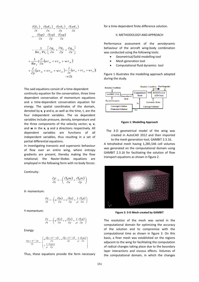
As analogous to the results rendered when
modelling the two dimensional tip airfoil, the lift
curve is generated as shown Figure 5.
Figure 5: Lift Coefficient vs. Mach Number
It is seen that lift is drastically reduced around
=0.85 with the effects of drag divergence
in the transonic regime become more
pronounced. The rise in dynamic pressure
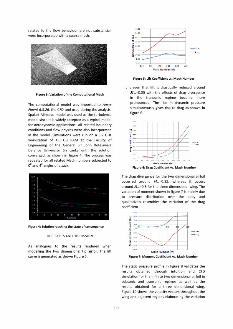
simultaneously gives rise to drag as shown in
figure 6.
Figure 6: Drag Coefficient vs. Mach Number
The drag divergence for the two dimensional airfoil
occurred around =0.85, whereas it occurs
around =0.8 for the three dimensional wing. The
variation of moment shown in figure 7 is mainly due
to pressure distribution over the body and
qualitatively resembles the variation of the drag
coefficient.
Figure 7: Moment Coefficient vs. Mach Number
The static pressure profile in figure 8 validates the
results obtained through intuition and CFD
simulation for the infinite two dimensional airfoil in
subsonic and transonic regimes as well as the
results obtained for a three dimensional wing.
Figure 10 shows the velocity vectors throughout the
wing and adjacent regions elaborating the variation
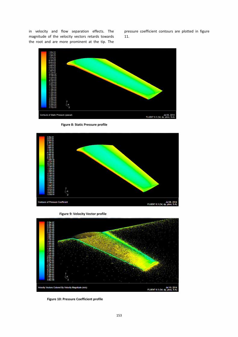
153
in velocity and flow separation effects. The
magnitude of the velocity vectors retards towards
the root and are more prominent at the tip. The
pressure coefficient contours are plotted in figure
11.
Figure 9: Velocity Vector profile
Figure 8: Static Pressure profile
Figure 10: Pressure Coefficient profile
154
IV. CONCLUSION
A three dimensional analysis of flow physics of a
finite wing having a NACA 64A212 airfoil tip and
NACA 64A114 root was conducted. The model
developed and data generated in this work will
serve as the basis for future work in modelling an
entire wing body combination for the real aircraft,
thereby generating solutions required to conduct a
complete performance analysis and possible design
modifications to enhance handling qualities of the
aircraft.
ACKNOWLEDGMENT
Authors highly acknowledge the support extended
by Mr. Ruwan Udayanandana, lecturer (Mechanical
Engineering) of the Sri Lanka Institute of Advanced
Technological Education in developing the 3-D
geometrical model of the aircraft wing.
LIST OF REFERENCES
Anderson, Jr, J.D. (2010), Aircraft Performance,
McGraw-Hill.
Anderson, Jr, J.D. (2011), Fundamentals of
Aerodynamics, 4th
Edition, McGraw-Hill.
FLUENT 6.3 User’s Guide (2006), Fluent Inc.
Tu, J., Yeoh, G.H. and Liu, C. (2008), Computational
Fluid Dynamics – A Practical Approach,
Buttcmurth-Heincmnn publications, UK.
Carmichael, R. (2010), 6A – Series Sections, Available
from http://www.pdas.com/sections6a.html
[accessed 10 Feb 2013].
Bandara, R. M. P. S. , & Abeygoonewardene, J. I. (2013).
Assessment of Aerodynamic Behaviour of the
NACA 64A212 airfoil on the context of
Computational Fluid Dynamics. Proceedings of
the KDU International Research Symposium, pp.
273-277 .
Shang, J. S., & Scherr, S. J. (1986, December). Navier
Stokes Solution for a Complete Re-entry
Configuration. J. Aircraft, Vol 23, No 12 , 881-
888.
BIOGRAPHY OF AUTHORS
1Author is a Senior Lecturer of
Aeronautical Engineering of General Sir
John Kotelawala Defence University
(KDU), Sri Lanka. Her research interests
include Flight Dynamics and Cooperative
and Autonomous Behaviour of Unmanned Aerial
Vehicles. She has served the Sri Lanka Air Force as an
Aeronautical Engineer for the past 16 years. Her
teaching areas include Aerodynamics, Aircraft Stability
& Control and Air breathing Propulsion.
2Author is a Senior Lecturer of
Mechanical Engineering of General Sir
John Kotelawala Defence University
(KDU), Sri Lanka. His research interests
include Computational Modelling and
Optimization of Energy Systems. At
present he holds the position of Head of Department of
Mechanical Engineering at KDU. He has 16 years of both
academic and industrial experience. His teaching areas
include Thermodynamics, Heat and Mass Transfer and
Computational Fluid Dynamics.