AIRPLANE FLIGHT MANUAL - VULFvulf.dk/onewebmedia/Savannah_POH.pdf · 72 l t Mogas/ A vgas IOO/IOO...
38
l I.C.P. Sri j Savannah FLIGHT MANUAL Pag. 11 AIRPLANE FLIGHT MANUAL / Issue l /Revision l Apr. Ol Savannah l l ICP Sri- Via Torino 12, 14020 PIOVA' MASSAIA (AT)- Italy Phone +39-0141-996503 • Fax +39-0141-996506
Transcript of AIRPLANE FLIGHT MANUAL - VULFvulf.dk/onewebmedia/Savannah_POH.pdf · 72 l t Mogas/ A vgas IOO/IOO...

l I.C.P. Sri j Savannah FLIGHT MANUAL Pag. 11
AIRPLANE FLIGHT MANUAL
/
Issue l /Revision l Apr. Ol
Savannah
l
l
ICP Sri- Via Torino 12, 14020 PIOVA' MASSAIA (AT)- Italy Phone +39-0141-996503 • Fax +39-0141-996506
l I.C.P. Sri J Savannah FLIGHT MANUAL Pag. 21
LIST OF THE EFFECTIVE PAGES
Page l 2 3 4 5 6 7 8 9 lO 11
12 13 14 15 16 17 18 19 20 21 22 23 24 25 26 27 28 29 30 31 32 33 34 35 36 37
Issue l /Revision 6 July'04
Conten t Is s u e Rev. Date Original l l Apr. Ol Original l 5 July '03 Original l 5 Ju~v '03 Original l l Apr. Ol Original l 2 July '03 Original l 6 July '04 Original l 2 Ott. 02 Original l 3 July '03 Original l 3 July '03 Original l 3 Julv '03 Original l 2 Ott. 02 Original l l Apr. Ol Original l l Apr. Ol Original l 4 July '03 Original l l Apr. Ol Original l l Apr. Ol Original l l Apr. Ol Original l 2 Ott. 02 Original l l Apr. Ol Original l l Apr. Ol Original l 2 Ott.02 Original l l Apr. Ol Original l l Apr. Ol Original l 2 Ott.02 Original l l Apr. Ol Original l l Apr. Ol Original l l Apr. Ol Original l 2 Ott. 02 Original l l Apr. Ol Original l l Apr. Ol Original l l Apr. Ol Original l 2 Ott. 02 Original l l Apr. Ol Original l 2 Ott. 02 Original l l Apr. Ol Original l l Apr. Ol Original l l Apr. Ol
ICP Sri- Via Torino 12, 14020 PlOV A' MASSAIA (AT)- Italy Phone +39-0141-996503 • Fax +39-0141-996506

l I.C.P. Sri l Savannah FLIGHT MANUAL Pag.31
LOG OF REVISIONS
Revision Revised Description o f Revision Date Number Pages
00 All Ol All 02 6 to11,18,
21,24,28, 32,34
03 2,3,14, 04 2,3,14 05 2,3,5,8,9,
10 06 2,3,6
Issue l /Revision 6 July '04
New emission 03/01 Cerreetions 04/01 Cerreetions 10/02
Cerreetion 10/02 N o te o n Instruments Ju1y '03
N o te o n Engine Ju1y '03
ICP Sri- Via Torino 12, 14020 PIOVA' MASSAIA (AT)- Italy Phone +39-0141-996503 • Fax +39-0141-996506

l I.C.P. Sri j Savannah FLIGHT MANUAL Pag. 41
SECTION l
SECTION2
SECTION 3
SECTION 4
SECTIONS
SECTION 6
Issue l /Revision l Apr. Ol
TABLE OF CONTENTS
AIRPLANE TECHNICAL DESCRIPTION
LIMITATIONS
EMERGENCYPROCEDURES
NORMALPROCEDURES
PERFORMANCE
WEIGHT AND BALANCE
ICP Sri- Via Torino 12, 14020 PlOV A' MASSAIA (AT)- Ita1y Phone +39-0141-996503 • Fax +39-0141-996506

l I.C.P. Sri l
Paragraph
1.1 1.2 1.3 1.4 1.5 1.6 1.7 1.8 1.9 1.10 1.11 1.12 1.13 1.14 1.15 1.16 1.17
Savannah FLIGHT MANUAL
TABLE OF CONTENTS
SECTION l
AIRPLANE TECHNICAL DESCRIPTION
Airplane three view and general specifications General specifications Structure Landing gear Engine Engine controls Propeller Fuel system Electrical system C ab in Cabin features and upholstery Ventilation Cabin heating Instrument panel Flight controls Flaps control system Pitot-static system Baggage compartment
Page
6 7 8 8 8 8 9 9 lO lO 11 11 11 14 15 15 15 15
Pag. si
Issue l/Revision 2 July'03
ICP Sri- Via Torino 12, 14020 PlOV A' MASSAIA (AT)- Italy Phone +39-0141-996503 • Fax +39-0141-996506
l I.C.P. Sri l Savannah FLIGHT MANUAL Pag. 61
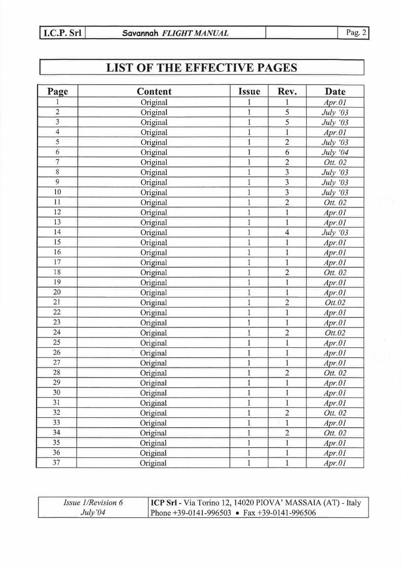
AIRPLANE THREE VIEW
- 2580 --
Issue l /Revision 6 july. 04
ICP Sri- Via Torino 12, 14020 PlOV A' MASSAIA (AT)- Ita1y Phone +39-0141-996503 • Fax +39-0141-996506

l I.C.P. Sri ( Savannah FLIGHT MANUAL Pag. 71
I.I GENERAL SPECIFICATIONS
Dimensions Wing span 30.0/9.0 ft/m Wing area I41/I2.7 sq. ft/m2
Length 2I.3/6.5 ft/m Height 8.0/2.45 ft/m Propeller diameter 68/I.73 in/m
w, . h · ·ezgJ ts
Maximum take-off weight I000/454 Ibs/kg Em_Qty weight 600/272 Ibs/kg Usefulload 400/I82 l b s/kg NOTE: empty weight may increase and is depended on the optional equipment instalied as per the customer requirements p l owerp, ant Engine Take off performance Dispiacement Compression ratio Fuei consumption (75% power)
Fuel and oil Fuel capacity Fuel grade Oil capacity
L d. an mg gear Wheel track Tire size Tire pressure
Issue l /Revision 2 Ott. 02
DIMENSION ROTAX9I2 UL ROTAX9I2 ULS 59.6 kW (5800 rpm) 75.3 kW (5800 rpm)
cu.in/cm3 73.9/12II 82.5/1352 9.0:I I0.5:I
gphllt/h 4.3/16.2 4.9/18.5
72 l t Mogas/ A vgas IOO/IOO LL 3/3.I6 lt/US qts
5.6/1.7 ft/m 6 m I4.5/I p silbar
ICP Sri- Via Torino I2, I4020 PIOVA' MASSAIA (AT)- Italy Phone +39-0I4I-996503 • Fax +39-0I41-996506

l I.C.P. Sri l Savannah FLIGHT MANUAL Pag. s j
1.2 STRUCTURE
The aircraft is a monoplane type, with two side-by-side seats, fitted with a high wing supported by struts. The wing presents a "high lift" NACA 650-18 modified airfoil with fixed slats along the full wingspanand Junkers type flaperon (aileron +flap). The airframe structure is a fullmetal one with load-resisting panels. The horizontal tailplane features a simmetric bi-convex airfoil. The rudder is attached to the fixed vertical fin. The dorsal fin is fitted to improve the directional stability.
1.3 LANDING GEAR
The aircraft is fitted with a tri-cycle type landing gear. The main landing gear is made by a single-piece aluminium alloy single-leafleg. The noselanding gear is fitted with a telescopic, elastic chord shock absorber, and is steerable in order to ease the taxying.
1.4 ENGINE
The engines instalied onboard the aircraft are the ROTAX 912 ULS or ROTAX 912 UL. Piease refer to Engine manual for any data and specifications. W ARNING: the instalied engine, by its design is subject to sudden stoppage. Engine stoppage can result in crash landings, forced landings or no power landings. Such crash landings can le ad to serious bodil y in jury o r de a th. N ever fly the aircraft equipped with the en gine at locations, airspeeds, altitudes, or other circumstances from which a successful no power landing eannot be made, after sudden engine stoppage. Aircraft equipped with this engine must only fly in DAYLIGHT VFR conditions. The instalied engine is not a certificated aircraft engine. It has not received any safety or durability testing, and conforms to no aircraft standards. This is for use in experimental, uncertificated aircraft and vehicles only in which an engine failure will not compromise safety. User assumes all risk of use and acknowledges by his use that he knows this engine is subject to sudden stoppage.
1.5 ENGINE CONTROLS
There are two vemier type (push-pull) throttle controls fitted with a frietion adjusting knob. The mixture control is located near to pilot's side throttle control. The air-box control (Rotax 912 ULS) is located near the throttle control: pull for hot air to carburators, push for cold air to carburators (for values oftemperature to maintain see chapter 2.3).
The key-operated master switch connects the electrical system to the 12V battery. The whole electrical system is protected bythermal type re-settable breakers.
The engine can be operating with the master switch OFF and the breakers OFF since the ignition system is independent and can be cut-offby switching OFF the two magneto switches only. With the master switch OFF any electrical instrument and all other electrical devices, electric engine starter included, won't be operating.
W ARNING: The engine may be started-up with the master switch OFF if even one magneto switch only is ON, when the propeller is hand rotating or due to windmilling. For safety, it's strongly recommended to pull-out the master switch key when the engine is shut-off.
Issue l/Revision 3 ICP Sri- Via Torino 12, 14020 PlOV A' MASSAIA (AT)- Italy July '03 Phone +39-0141-996503 • Fax +39-0141-996506

l I.C.P. Sri j Savannah FLIGHT MANUAL Pag. 91
The master switch key is located near to the pilot's throttle. All the switches and the engine controls commute to ON if moved UPWARD or FOREWARD. The mixture control only, is activated pulling it BACKWARD.
1.6 PROPELLER
The aircraft features the foliowing propeller: "DUC Helice", 3 blades in carbon fiber (Rotax 912 ULS), adjustable on ground.
- "DUC Helice", 2 blades in carbon fiber (Rotax 912 UL), adjustable on ground.
1.7 FUEL SYSTEM
With reference to fig. l on page 11, the fuel system is equipped with two tanks (1, 2). They are instalied into the wings and have a 72 lt. capacity. The filler caps inelude a vent hole. The reservoirs features an overcapacity fuel pipe ending below the wing. The left fuel tank is with a visual fuel level indicator located on left wing first rib. The drain valve (5.) is located in the fuel bowl (3.) instalied in the fuselage, o n the right side; a fuel reserve warning is instalied o n the bowl to indicate low remaining fuel. A fuel valve is fitted (7.): this fuel valve is held in the OPEN position by a safety wire. That safety wire can be broken in an emergency. This safety wire must be used to prevent an accidental in-flight fuel valve elosure leading to an engine shut-down or, even worse, to a elosed fuel valve take-off. The fuel pump (8.) is mechanically cams operated. A fuel pressure gauge is installed.
Issue l/Revision 3 July'03
ICP Sri- Via Torino 12, 14020 PlOV A' MASSAIA (AT)- Italy Phone +39-0141-996503 • Fax +39-0141-996506
l I.C.P. Sri l Savannah FLIGHT MANUAL l Pag. 10 l
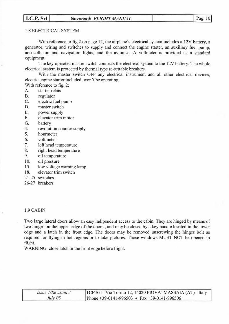
1.8 ELECTRICAL SYSTEM
With reference to fig.2 on page 12, the airplane's electrical system ineludes a 12V battery, a generator, wiring and switches to supply and connect the engirre starter, an auxiliary fuel pump, anti-collision and navigation lights, and the avionics. A voltmeter is provided as a standard equipment.
The key-operatedmaster switch connects the electrical system to the 12V battery. The whole electrical system is protected by thermal type re-settable breakers.
With the master switch OFF any electrical instrument and all other electrical devices, electric engirre starter included, won't be operating. With reference to fig. 2: A. starter relais B. regulator C. electric fuel pump D. master switch E. power supply F. elevator trim motor G. battery 4. revolution counter supply 5. hourmeter 6. voltmeter 7. left head temperature 8. right head temperature 9. o il temperature l O. oil pressure 15. low voltage waming lamp 18. elevator trim switch 21-25 switches 26-27 breakers
1.9 CABIN
Two large lateral doors allow an easy indipendent access to the cabin. They are hinged by means of two hinges on the upper edge o f the doors , and may b e closed by a key handle located in the lo w er edge and a latch in the front edge. The doors may be removed unscrewing the hinges bolt as required for flying in hot regions or to take pictures. Those windows MUST NOT be opened in flight. W ARNING: close latch in the front edge before flight.
Issue l/Revision 3 July'03
ICP Sri- Via Torino 12, 14020 PlOV A' MASSAIA (AT)- Italy Phone +39-0141-996503 • Fax +39-0141-996506

l I.C.P. Sri l Savannah FLIGHT MANUAL l Pag. ni 1.10 CABIN FEATURES AND UPHOLSTERY
The cabin arrangement features two canvas covered side-by-side seats.
1.11 VENTILATION
The cabin's ventilation is provided by an opening between the doors and the upper part of the cabin door frame. A dynamic air scoop intended to extract the cabin air is fitted at the hottom of the baggage compartment lt's possible to improve the cabin ventilation by using two rotating air scoops in the doors windows. lt's important to get an efficient cabin ventilation to avoid the windshield frosting in high humidity, low temperature and rainy weather.
1.12 CABIN BEATING
On the right-upper side ofthe instruments panel there is a push-pull control. Pullit for havingahot ventilation in the cockpit.The outlet may be opened by a rotating panel on the cockpit skin. The air is heated by the heat exehanged integrated the silencer.
Issue l !Revision 2 Ott. 02
ICP Sri- Via Torino 12, 14020 PIOVA' MASSAIA (AT)- Italy Phone +39-0141-996503 e Fax +39-0141-996506

l I.C.P. Sri l FUELSYSTEM
Issue l /Revision l Apr. Ol
Savannah FLIGHT MANUAL l Pag. 12j
..:
Pigure nr.l
( l l l l l l l
/
\
/ /
-/
' ' '
--, l l l l l l
~l
Hl l l
IIII l l l ..... ____ .J
ICP Sri- Via Torino 12, 14020 PlOV A' MASSAIA (AT) -ltaly Phone +39-0141-996503 • Fax +39-0141-996506

j I.C.P. Sri l Savannah FLIGHT MANUAL
ELECTRIC SYSTEM
...... ~-"""'il
..!::::.o:. -
~ 3 § ·1-H---+----' ~
----t---w
K1 ~ ~ ~ r.pp----1
~ ~~~~~----_j
.r- ~r--
~ l~ ! l w z l .....
L:J z w
r---
_j Figure nr.2
l Pag. 13j
Issue l /Revision l Apr. Ol
ICP Sri- Via Torino 12, 14020 PlOV A' MASSAIA (AT)- Italy Phone +39-0141-996503 • Fax +39-0141-996506

l I.C.P. Sri l Savannah FLIGHT MANUAL l Pag. 141
1.13 INSTRUMENT PANEL ATTENTION: the instalied instrumentsarenot certified according to any aeronautical regulation: it is advisable to avoid dangerous flight conditions and do not consider the values given by the instruments as an absolute value.
As standard equipment the foliowing instruments are fitted:
Fuel pump_,
l Choke o.ctuotor"' I b Airbox contr"ol (Ont y Rotox 912 ULS> 2 Moster switch 3 ,4 Magneta swltche s 5 Pilot s ide occeter atol"' 6 PT T swit ch <optionan 7 Elev o t or triM s witch 8 not u s ed 9 Aner'lOr'le t er lO Al t1Meter 11 Vorio l"''eter 12 Rodio - intercoM <optlon o l) 13 Revolution co~,.~nter 14 Fuel preSSl,.lr"E' indicotor 15 Slip incl ico tor" 16o Left cylinder head t eMpera t ure l6b Right c ylinde r head teMpera t u re 17 Externol ter~pe ro. t ur" e <9 12 UU + A1r!oox teMpera t ur-e <9 12 ULS) 17b Switc h exte rnol t eMperuture - oirbo x teMpera t ure (only 912 UL S) 18 Oil pr essur e indico t or 19 Dit ter~per o. ture indico tor 20 Ho un "'ete r 2 1 Vol t Meter 22 Low bo tt ery vattoge wor ning l oMp 23 Possenger s ide occe terotot" 24 Reserve f'ue t tonk (Nut" is e) t est button 25 Fuel r e serve wo.rning lo Mp
Position lights (optional) / Co bin light
/ Strobe
0 0 l
l lereaker 1 O A La nding light
Instruments for each aircraft may vary according to the requirernents o f the customers. Issue l/Revision 4 ICP Sri- Via Torino 12, 14020 PlOV A' MASSAIA (AT)- Italy
July '03 Phone +39-0141-996503 • Fax +39-0141-996506
l I.C.P. Sri l Savannah FLIGHT MANUAL IPag.15j
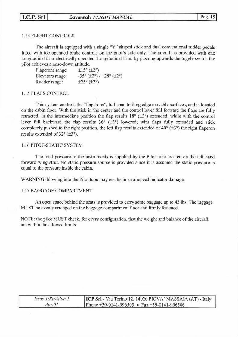
1.14 FLIGHT CONTROLS
The aircraft is equipped with a single "Y" shaped stick and dual conventional rudder pedals fitted with toe operated brake controls on the pilot's side only. The aircraft is provirled with one longitudinal trim electrically operated. Longitudinal trim: by pushing upwards the toggie switch the pilot achieves a nose-down attitude.
Flaperons range: ±15° (±2°) Elevators range: -35° (±2°) l +28° (±2°) Rudder range: ±25° (±2°)
1.15 FLAPS CONTROL
This system controls the "flaperons", full-span trailing edge movable surfaces, and is located on the cabin floor. With the stick in the center and the control lever full forward the flaps are fully retracted. In the intermediate position the flap results 18° (±3 °) extended, w hil e with the contro l lever full backward the flap results 36° (±3°) lowered; with flaps fully extended and stick completely pushed to the right position, the left flap results extended of 40° (±3°) the right flaperon results extended of32° (±3°).
1.16 PITOT-STATIC SYSTEM
The total pressure to the instruments is supplied by the Pitot tube located on the left hand forward wing strut. No static pressure source is provirled since it is assumed the static pressure is equal to the pressure inside the cabin.
WARNING: biowing into the Pitot tube may results in an airspeed indicator damage.
1.17 BAGGAGE COMPARTMENT
An open space behind the seats is provirled to carry some baggage up to 45 lbs. The luggage MUST be evenly arranged on the baggage compartment floor and firmly fastened.
NOTE: the pilot MUST check, for every configuration, that the weight and balance ofthe aircraft are within the allowed limits.
Issue l/Revision l Apr. Ol
ICP Sri- Via Torino 12, 14020 PlOV A' MASSAIA (AT)- Italy Phone +39-0141-996503 • Fax +39-0141-996506

l I.C.P. Sri l
FLIGHT CONTROLS
Issue l /Revision l Apr. Ol
Savannah FLIGHT MANUAL
11 J
l <1:
f l ~
l \ CL
l \ l l
} \ l
l
Figure nr.3
z o C< w ..J
4
l Pag. 16j
ICP Sri- Via Torino 12, 14020 PlOV A' MASSAIA (AT)- Italy Phone +39-0141-996503 • Fax +39-0141-996506

l I.C.P. Sri j
Paragraph
2.1 2.2 2.3 2.4 2.5 2.6 2.7 2.8
Savannah FLIGHT MANUAL
Speed limits Load factors Engine operating limits Weight !imitations C o f G !imitations Kind o f operations Kind o f maneuverings
TABLE OF CONTENTS
SECTION2
LIMIT A TIONS
Max crosswind for T/0 and landing
l Pag. 171
Page
18 18 18 19 19 19 19 19
Issue l /Revision l Apr. Ol
ICP Sri- Via Torino 12, 14020 PlOV A' MASSAIA (AT)- Italy Phone +39-0141-996503 • Fax +39-0141-996506

l I.C.P. Sri l Savannah FLIGHT MANUAL l Pag.181
2.1 SPEED LIMITS
NOTE h ti U : t e o owmg spee 1m1ts d r · (IAS) Stall SQ_eed, full flaps, Vso Flaps range (white arc) Stall speed, n o flaps, V s Normal operating range (green arc) Max. maneuvering speed (l) Attention zone (yellow arc) (2)
Vmo Never exceeding speed, Vne (red line) Flaps speed limit
NOTES:
are set a a max1mum a e o w e t t k ff ight of 1000 lbs/454 kg 30 mph l 48 km/h 30-60 mph l 48-96 km/h 35 mph l 56 km/h 'Y, j /-1. ~.J l) . j
40-85 mph l 64-13 7 km/h 70 mph l 112 km/h 85-125 mph l 137-201 km/h 100 mph l 160 km/h 125 mph l 201 km/h 60 mph l 96 km/h
2
·~6 l> ~
,_ 70 l
'"6c-11.2 ~ 9 -'/ 2 .":}
(1): the maximum maneuvering speed is the maximum speed at which the flight controls may be fully operated (maximum movable surfaces detleetion angles); (2): when flying in turbulence conditions this speed range has to be avoided.
2.2 LOAD FACTORS Fia s retracted + 4 Fia s full extended + 2
NOTE: the maximum load factors (limit load factors) are obtained multiplying theabove indicated values by the coefficient 1,5.
2.3 ENGINE OPERA TING LIMITS • Maximum RPM for T/0 and climb • Caution range • Normal range • Maximum continuous power • Idle speed • Oil pressure
• Oil temperature
• Fuel pressure
• Air-box temperatures (Only 912 ULS)
5800 RPM (5 min.) (red line) 5500-5800 RPM (yellow arc) 1400-5500 RPM (green arc) 5500 RPM around 1400 RPM normal range 2-5 bar (29-73 psi) (green arc) caution range5-7 bar (73-102 psi) (yellow arc) min. 0.8 bar (12 psi) (red line), max 7 bar (102 psi) (red line) normal range 90-11 O o c (green arc) caution range 50-90 l 110-140 oc (yellow arc) max 140 °C (red line) max 0.4 bar (5.8 PSI) Min 0.15 bar (2.2 PSI) Caution range 18 o c - 20 °C (yellow arc) Caution range 24 oc- 35 °C (yellow arc) Normal range 20 oc- 24 °C (green arc) Minimum air box temp. 18 °C Maximum air-box temp. 35 °C (red line)
Issue l /Revision 2 Ott. 02
ICP Sri- Via Torino 12, 14020 PIOVA' MASSAIA (AT)- Italy Phone +39-0141-996503 • Fax +39-0141-996506

l I.C.P. Sri l Savannah FLIGHT MANUAL
2.4 WEIGHT LIMITATIONS
Maximum tak e off weight: Minimum take offweight (minimum pilot weight 86 kg and~ h flight fuel):
2.5 C ofG LIMITATIONS
Forward C of G limit: Rear C ofG limit:
See also section 6.
2.6 KIND OF OPERATIONS
30%MAC 38.5%MAC
The airplane can b e operated only in da y-VFR conditions.
2. 7 KIND OF MANEUVERINGS
The airplane is intended for non-aerobatic operations only.
2.8 MAX CROSSWIND FOR T/0 AND LANDING
'1s-o Is -454 kg 367 kg
The maximum cross-wind component allowed during take-off and landing is 30/48 mph/km/h.
Jssue I /Revision l Apr. Ol
---
ICP Sri- Via Torino 12, 14020 PlOV A' MASSAIA (AT)- Italy Phone +39-0141-996503 • Fax +39-0141-996506

l I.C.P. Sri l
Paragraph
3.1 3.2 3.3 3.4 3.5 3.6 3.7
3.8
Savannah FLIGHT MANUA~
Emergency landing Fire on the ground
TABLE OF CONTENTS
SECTION 3
EMERGENCYPROCEDURES
Fire on the ground, engine operating In flight fire Cabin fire Unintentional spins Engine failure during T/0 (on the ground) or immediately after T/0 (lo w altitude) Engine start during flight
l Pag. 20 1
Page
21 21 21 21 21 21 22
22
Issue l /Revision l Apr. Ol
ICP Sri- Via Torino 12, 14020 PlOV A' MASSAIA (AT)- Italy Phone +39-0141-996503 • Fax +39-0141-996506

l I.C.P. Sri J Savannah FLIGHT MANUAL l Pag. 211
3.1 EMERGENCY LANDING
Best descent ratio speed 60 mph/96 km/h Flaps Retracted Fuel valve Shut-off Engine Shut-off Seat helts Fastened and tightened Steep tums Avoid Flaps in final Fully extended, 40° Landing N ormallanding
3.2 FIRE ON THE GROUND
Starter Keep engaged Fuel valve Shut-off Throttle Fully open, to bum the fuel and stop the fire
3.3 FIRE ON THE GROUND, ENGINE OPERATING
Fuel valve Throttle
3.4 IN FLIGHT FIRE
Fuel valve Engine
Electrical system Landing
3.5 CABIN FIRE
Electrical system Fire extinguisher
3.6 UNINTENTIONAL SPINS
Rotation
Control stick Upon taking aircraft's control
Issue l /Revision 2 Ott. 02
Shut-off Fully open, to bum the fuel and stop the fire
Shut-off Stop Don't trv to restart the engine All switches OFF Go on to an emergency landing
All switches OFF Operate
To stop the rotation push the pedal opposite the rotation direction Center, slightly forward Level flight attitude
ICP Sri- Via Torino 12, 14020 PIOVA' MASSAIA (AT)- Italy Phone +39-0141-996503 • Fax +39-0141-996506

l I.C.P. Sri l Savannah FLIGHT MANUAL l Pag. 221
3.7 ENGINE F AlLURE DURING T/0
Magneto switches OFF Master switch OFF Throttle Idle Fuel valve Shut-off Brak e Fully operated
Immediately after take off
Airspeed Keep 60 m ph lAS and firs t notch o f flap Evenmallanding Check for adequate spaces within 30° left and
30° right Throttle 50%, fuel pump ON and _!!y to restart the engine lf previous point fails Before touching the ground, magnetces OFF,
master switch OFF, throttle i dl e, fuel val ve shut off
Flaps Fully deflected On the ground Touch and brake
3.8 ENGINE START DURING FLIGHT
Throttle Magneto switches Master switch Fuelpump Restart the engine RPM
Issue l /Revision l Apr. Ol
l dl e ON ON ON ------·-·--
As requested for the type o f flight
ICP Sri- Via Torino 12, 14020 PlOV A' MASSAIA (AT)- Italy Phone +39-0141-996503 • Fax +39-0141-996506

l I.C.P. Sri l Savannah FLIGHT MANUAL l Pag. 231
TABLE OF CONTENTS
SECTION 4
NORMALPROCEDURES
Paragraph Page
4.1 Before flight checks 24 4.2 Exterior checks 24 4.3 Engine start-up 24 4.4 Taxying 26 4.5 Before to take-off 26 4.6 Take-off and climb 27 4.7 Cruise 28 4.8 Descent 28 4.9 Approach and landing 28 4.10 Cross-wind landing 29 4.11 Aborted landing (Go-around) 29 4.12 Engine shut-down 29 4.13 Parking and mooring 29
Issue l /Revision l Apr. Ol
ICP Sri- Via Torino 12, 14020 PlOV A' MASSAIA (AT)- Italy Phone +39-0141-996503 • Fax +39-0141-996506

j I.C.P. Sri l Savannah FLIGHT MANUAL l Pag. 24j
NOTE: The flight characteristics of the Savannah are conventional. There is no needing of exceptional piloting skilis to manage the aircraft within its flight envelope.
4.1 BEFORE FLIGHT CHECKS
Master switch OFF Magnetos OFF Fuel selector OPEN Flight controls UNLOCKED Fuel gascolator DRAIN Powerplant fairings FASTENED Pre-flight/Daily inspection PERFORM
4.2 EXTERIOR CHECKS
Propeller andengine Visual check to bolts and nuts, oilleaks Forward landing gear Visual check o f connection pionts Main landing gear and strut attachments Visual check to bolts and nuts Slat Ailerons Horizontal and vertical tail Coolant radiator
4.3 ENGINE START-UP
COLDENGINE Master switch Magnetos Brak es Throttle Chok e Starter NOTE
Issue l /Revision 2 Ott. 02
Visual check to damages and dirt Visual check ofhinges boltsand nuts Visual check to attachment bolts and nuts Visual check to absence o f dirt, insects
ON ON OPERA TE FULL Y CLOSED ON ENGAGE Upon enginestart-up let the enginerun for some seconds then gradually release the mixture contro l while slightly pushing the throttle contro l
ICP Sri- Via Torino 12, 14020 PlOV A' MASSAIA (AT)- Italy Phone +39-0141-996503 • Fax +39-0141-996506

l I.C.P. Sri j Savannah FLIGHT MANUAL j Pag. 251
HOTENGINE NOTE Perform the same as for COLD ENGINE items
except pulling the choke control NOTE The engine starts easily with the throttle full
closed. In case o f fuel flooding only i t' s useful to open the throttle to supply a large amount of air to recreate the normal carburation condition.
NOTE It's strongly recommended the pilot, immediately before to engage the engine starter, call with loud vmce "BEWARE OF PROPELLER". Then, upon making sure himself none is close to the propeller, he can start the engine. If someone is standing close to the aircraft, it would be his responsibility to stay away enough and answer the pilot "PROPELLER CLEARED".
Engine warm-up W AlT FOR PROPER CHT READ ING Instruments operation CHECK Windshield cleanliness CHECK Brake effectiveness CHECK Safety belts and shoulder hamesses FASTENED AND CHECKED Fuel quantitv Electrical devices operation
Issue l /Revision l Apr. Ol
CHECK CHECK
ICP Sri- Via Torino 12, 14020 PlOV A' MASSAIA (AT)- Italy Phone +39-0141-996503 • Fax +39-0141-996506

l I.C.P. Sri J Savannah FLIGHT MANUAL J Pag. 26j
4.4TAXYING
POWER Apply reduced enginepower and use the brakes at the minimum
S TE ERIN G The steering should be obtained by using the rudder pedals and not the brakes
CROSSWIND In the event of a stronger than 19 mph/30 km/h crosswind, taxy at a very low speed and move the control stick laterally towards the up-wind wing; this will raise the up-wind wing flaperon thus avoiding the wing accidental raising.
NOTE U se rudder holding the heels o n the floor: in that way there will be no accidental brake operation.
4.5 BEFORE TAKE-OFF
Altimeter AD JUST Trim ADJUST to neutral position Flaps retracted CHECK Flight controls freedom o f movement and correct CHECK movement o f surfaces Doors closed and locked CHECK Safety helts fastened CHECK Fuellevel CHECK Engine instruments, green arc CHECK NOTE The engine has been running at 2.500/3.000
RPM while warming-up; the CHT reading has risen to 60 °C.
Magnetos; check the RPM drop: one magneto at CHECK a time at 3.000 RPM (the max. allowed speed drop with only one ignition circuit is 300 RPM) (the max difference o f speed by use of either circuit is 115 RPM max) Magnetos BOTHON Full power check ASREQUIRED Runway and circuit traftic CLEARANCE CHECK Runway threshold LINE-UP
Issue l/Revision l Apr. Ol
ICP Sri- Via Torino 12, 14020 PIOVA' MASSAIA (AT)- Italy Phone +39-0141-996503 • Fax +39-0141-996506

l I.C.P. Sri l Savannah FLIGHT MANUAL j Pag. 271
4.6 TAKE-OFF AND CLIMB
Flaps, 20° SET Brak es RELEASED Throttle (operate progressively) FULL Y OPENED Engine RPM CHECKE D Air-box control COMPLETEL Y PUSHED FOR COLD AIR Control stick SLIGHTL Y PULLED NOTE The aircraft will take-off at a 30-35 mph speed
and will keep climbing at a 40-45 mph speed NOTE While take-off running, be sure to hold your
heels in contact with the cabin floor to avoid to inadvertently operate the brakes
Flaps, at a safety altitude FULL Y RETRACTED Climb airspeed at 60-65 mph SET Upon reaching the required altitude LEVEL Cruise speed as required, RPM as required SET Trim (to get no reaction on the control stick) SET
SHORT TAKE OFF Flaps, 40° SET Brak es FULL Y APPLIED Throttle FULL Y OPENED Air-box control COMPLETBLY PUSHED FOR COLD AIR Brak es RE LEAS ED Pilot's heels ONTHEFLOOR Nose-up attitude, control stick pulled-on until SET ANDHOLD taking off Climb airspeed at 45 mph until the 50 ft obstacle SET clearing Flaps, upon reaching a safe altitude and airspeed FULL Y RETRACTED NOTES:
- the hest rate of climb makes the aircraft climb to the required altitude in the shortest flight time;
- the hest angle of climb makes the aircraft climb to the required altitude in the shortest distance;
- in normal flight conditions, set the flaps to 20° to shorten the take-off roll in ord er to clear a 50 ft. high obstacle. That's possible since the aircraft flies at a lower airspeed but the extended flaps decrease the rate of climb.
- in case of operation from high elevation airfields andfor at high ambient temperature the extended flaps induced drag increase affects the aircraft's performance as far as to increase the takeoff run. So it's recommended to check the take-off performance chart to determine if it is advantageous the flaps extension in the take-off.
The above indicated data are medium ones since they may be varied with relation to the aircraft's weight, balance and configuration.
Issue l/Revision l Apr. Ol
ICP Sri- Via Torino 12, 14020 PIOVA' MASSAIA (AT)- Italy Phone +39-0141-996503 • Fax +39-0141-996506

l I.C.P. Sri l Savannah FLIGHT MANUAL l Pag. 28j
4.7 CRUISE
The cruising speed is achieved by applying the 75% of the engirre power available at the propeller. Normally the propeller required power (fixed pitch propeller only) decrease by 50% foliowing a 20% RPM decrease only. So, at a constant aircraft's configuration, the propeller will use the full engirre power (full RPM) while, at 4.600 RPM, the propeller will be supplied with half the full engirre power.
The cruise speed is 90 mph (5000rpml27.2in.HG) with Rotax 912 UL and 95mph (5000rpml26 in.HG) with Rotax 912 ULS; remember that the fastestwill run the engirre the highest will be its fuel consumption and the lowest its operating life, while a slow running engine, for the same power output, will have its mechanical components loaded by greater forces and torques, thus increasing the risk to break rods, crankshaft and the other moving (rotating) parts. Low RPM settings DON'T increase safety!
Low RPM settings produce low power output thus a lower airspeed would be achieved. By increasing the flight attitude the engirre power output will decrease as well as the
propeller's thrust: to compensate it, it's required to increase the engine's RPM. The normal engirre running speed is 4,000 to 5,400 RPM.
The engirre has been designed to be safely and continuously operated at the maximum RPM settin g.
Air-box control: keep 20-24 oc oftemperature. (Only Rotax 912 ULS)
4.8 DESCENT
During the descentit's recommended not to operate the engirre at idle to avoid a hard engirre cooling which could lead to cylinder heads cracks.
Keep air-box control pulled for hot air.
4.9 APPROACH AND LANDING
Throttle IDLE Airspeed 60 mph l 97 km/h (lAS) Flaps 20 o
Airspeed 45 mph (lAS) Flaps 40° Airspeed 40 mph l 64 km/h (lAS) Brakes, upon touching down APPLY
If a higher rate of descent is required, fully extend the flaps. The angle of the descent path may be slightly varied by throttle operation as required to modify the gliding path. The flare will be flown in a nose-up attitude. Upon touching down, by releasing the control stick, the aircraft's nose willlower.
If downwind attitude, keep air-box controlpushed for cold air. (Only Rotax 912 ULS)
Issue l /Revision 2 Ott. 02
ICP Sri- Via Torino 12, 14020 PlOV A' MASSAIA (AT)- Italy Phone +39-0141-996503 • Fax +39-0141-996506

l I.C.P. Sri l Savannah FLIGHT MANUAL l Pag. 291
4.1 O CROSS-WIND LANDING
l
In the event of a crosswind the approach has to be flown lowering the up-wind wing or applying the yaw control to achieve a nose-into-the-wind aircraft's attitude or using both the two control techniques at the same time as required.
The aircraft mustbelined-up along the runway shortly before the ground contact. The maximum cross-wind component allowed during take-off and landing IS 30/48
m ph/km/h.
4.11 ABORTED LANDING (GO-AROUND)
Throttle, full power SET Flaps, when reaching a 54 mph (lAS) airsp_eed RETRACT
The throttle control must be pushed smoothly and gradually to avoid an engine flooding or, worse, anengine shut-down.
4.12 ENGINE SHUT-DOWN
Engine operating, low RPM 2MINUTES Throttle IDLE Magnetos OFF Master switch OFF
It's recommended to keep the engine running at low RPM for as long as two minutes in order to avoid a thermal shock and to achieve a thermal balance between the different engine's components. Moreover it will be achieved a good pistons and piston rings lubrication so the engine will be let in the hest condition to the next start-up.
4.13 PARKING AND MOORING
To moore the aircraft tie two ropes to the mooring rings fitted under the wings (bolted to the the wing spar) and a third one to the rear mooring ring.
Tie the control stick together with the rudder pedals by using an elastic chord to lock all the movable surfaces.
Make sure the doors are closed and locked. Put in place the optional windshield and windows proteetion canvas to prevent dust
accumulation and scratches.
Issue l /Revision l Apr. Ol
ICP Sri- Via Torino 12, 14020 PIOVA' MASSAIA (AT)- Italy Phone +39-0141-996503 • Fax +39-0141-996506

l I.C.P. Sri j
Paragraph
5.1 5.2 5.3 5.4
Savannah FLIGHT MANUAL
Stall speed Take-off run
TABLE OF CONTENTS
SECTION 5
PERFORMANCE
Landing distances from 15 m and landing run Rate of climb
j Pag. 30 l
Page
31 31 31 32
Issue l /Revision l Apr. Ol
ICP Sri- Via Torino 12, 14020 PlOV A' MASSAIA (AT)- Italy Phone +39-0141-996503 • Fax +39-0141-996506
l I.C.P. Sri l Savannah FLIGHT MANUAL l Pag. 3Ij
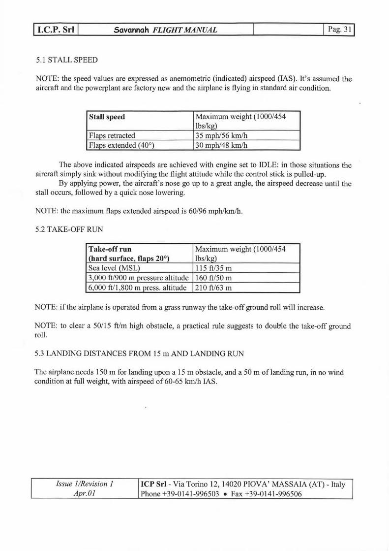
5.1 STALL SPEED
NOTE: the speed values are expressed as anemometric (indicated) airspeed (lAS). It's assumed the aircraft and the powerplant are factory new and the airplane is flying in standard air condition.
Stall speed Maximum weight (l 000/454 l b s/kg)
Flaps retracted 35 mph/56 km/h Flaps extended ( 40°) 30 mph/48 km/h
The above indicated airspeeds are achieved with engirre set to IDLE: in those situations the aircraft simply sink without modifying the flight attitude while the control stick is pulled-up.
By applying power, the aircraft's nosego up to a great angle, the airspeed decrease until the stall occurs, followed by a quick nose lowering.
NOTE: the maximum flaps extended airspeed is 60/96 mph/km/h.
5.2 TAKE-OFF RUN
Take-off run Maximum weight (l 000/454 l (hard surface, flaps 20°) Ibs/kg) Sea level (MSL) 115ft/35m 3,000 ft/900 m pressure altitude 160ft/50 m 6,000 ft/1,800 m press. altitude 210 ft/63 m
NOTE: ifthe airplane is operatedfrom a grass runway the take-off ground roll will increase.
NOTE: to clear a 50/15 ft/m high obstacle, a practical rule suggests to double the take-off ground ro l l.
5.3 LANDING DISTANCES FROM15m AND LANDING RUN
The airplaneneeds 150m for landing upon a 15m obstacle, and a 50 m oflanding run, in no wind condition at full weight, with airspeed of 60-65 km/h lAS.
Issue l/Revision l Apr. Ol
ICP Sri- Via Torino 12, 14020 PlOV A' MASSAIA (AT)- Italy Phone +39-0141-996503 • Fax +39-0141-996506

l I.C.P. Sri l Savannah FLIGHT MANUAL l Pag. 32j
5.4 RATE OF CLIMB (Rotax 912 UL)
Rate of climb Maximum weight (l 000/454 Full power setting Ibs/kg) Sea level (MSL) 1,100 fpm/5.5 m/s
48 mph/77 km/h 3,000 ft/900 m pressure altitude 790 fpm/4.0 m/s
45 mph/72 km/h 6,000 ft/1 ,800 m press. al titude 520 fpm/2.6 m/s
40 mph/64 km/h 9,000 ft/2,700 m press. attitude 300 fpm/1.5 m/s
3 7 mph/60 km/h
The maximum ceiling is 14,000 ft/4200 m pressure attitude at the maximum weight.
The hest rate o f climb speed is 48177 mph/kmlh.
The hest angle of climb speed is 45172 mphlkm/h.
The hest gliding angle with flaps retracted is achieved at a 60/96 mph/km/h airspeed. The Lift to Drag ratio is 12.
The fuel consumption at 75% power setting amounts to 4.9/18.5 gphllt/h for Rotax 912 ULS and 4.3/16.2 gphllt/h for Rotax 912 UL
lssue l /Revision 2 Ott. 02
ICP Sri- Via Torino 12, 14020 PlOV A' MASSAIA (AT)- Italy Phone +39-0141-996503 • Fax +39-0141-996506

l I.C.P. Sri l
Paragraph
6.1 6.2 6.3 6.4
Savannah FLIGHT MANUAL
TABLE OF CONTENTS
SECTION 6
WEIGHT AND BALANCE
General W eight and balance report W eight and balance drawings Weight and balance pilot' s computing table and graph
l Pag. 331
Page
34 35 36 37
Issue l/Revision l Apr. Ol
ICP Sri- Via Torino 12, 14020 PlOV A' MASSAIA (AT)- Italy Phone +39-0141-996503 • Fax +39-0141-996506
l I.C.P. Sri l Savannah FLIGHT MANUAL j Pag. 341
6.1 GENERAL
The aircraft is allowed to have its CG (Centre of Gravity) within a quite large range thus easing the aircraft's loading and balancing. By knowing the weights ofthe people, fuel and baggage to be carried on board and using the attached W &B report, the pilot would be ab le to check for the proper aircraft's weight and balance configuration. To find out the CG position piease refer to the attached table. Compute the total weight and the total moment, given by adding all the single moments. To be acceptable, the found point MUST be located into the WHITE area, between the two limit lines.
W ARNING: a CG beyond the most foreward limit, as well as a CG beyond the most rearward limit may result in a VERY DANGERODS flight condition.
NOTE: it's strictly forbidden to make any change or modification to the aircraft since those modifications may affect the balance limits set by the manufacturer.
Issue l/Revision 2 Ott. 02
ICP Sri- Via Torino 12, 14020 PlOV A' MASSAIA (AT)- Italy Phone +39-0141-996503 • Fax +39-0141-996506

l I.C.P. Sri l Savannah FLIGHT MANUAL l Pag. 351
6.2 WEIGHT AND BALANCEREPORT
Procedure to be used to determine the Centre o f Gravity position:
- The aircraft MUST be weighed fitted with all equipments, accessories, engine oil, coolant and WITHOUT FUEL;
NOTE: all the fuel MUST be drained accurately.
- Put the aircraft on three weight measuring equipments ( each under each wheel o f the landing gear); - Put the aircraft in the flight level position by using a level fitted o n the aircraft' s fuselage, o n the horizontal plane where doors will be closed; -Record the three weight measuring equipments readings: the nose wheel weight will be called Pl, the left wheel weight P2, the right wheel weight P3; - By using a plumbing wire fix ed to the leading edge, measure the distance D l between the projection on the floor o f the leading edge and the nose wheel axle, and the distance D2 between the same projected point and the main landing gear axle; - By filling out the table below, make the calculations and find out the CG position. The airplane is in the correct balance if the line o f the actual weight and the line o f the actual total moment cross inside the white area.
TABLE TO DETERMINE THE AIRCRAFT'S BASIC EMPTY WEIGHT
Aircraft serial number Weight measuring equipment Location and date Certifying staff
N ose landing gear
LH main landing gear
RH main landing gear
TOTALS
l Signature
Issue l /Revision l Apr. Ol
Weight (kg) Arm (m) Moment (kg x m)
PI = n,{), t L/5~s 71.. <,./'
P2= D2=€J ~ ,u
p3 = D2=fJ 7o,)-" /CJIX
ICP Sri- Via Torino 12, 14020 PlOV A' MASSAIA (AT)- Italy Phone +39-0141-996503 • Fax +39-0141-996506
\

l I.C.P. Sri l Savannah FLIGHT MANUAL
6.3 WEIGHT AND BALANCE DRA WINGS
where: D1=700mm; D2=700mm; P l =weight on forward gear; P2=total weight on principal gear; X=(P2*D)/(Pl +P2)-Dl X =-ff.-/ !J-
Z '?f~ l J.:Ttt -loo ' M
1 L-f f.- /foD' l -- (!; • ").
i i
- o
N Q_
' ' -
l Pag. 361
Issue l/Revision l Apr. Ol
ICP Sri- Via Torino 12, 14020 PlOV A' MASSAIA (AT)- Italy Phone +39-0141-996503 • Fax +39-0141-996506

l I.C.P. Sri l Savannah FLIGHT MANUAL l Pag. 37j
6.4 WEIGHT AND BALANCE PILOT'S COMPUTINO TABLE AND GRAPH
COMPUTING TABLE
Item Weight W [Ibs] ArmX[m] Basic em_Q_ty weight Ino '-1, (;.,ot.t O,'tt'J Pilot IC.? /(. :-; 0.65 Passeng~r /LO! t L_, t_,, 0.65 Fuel (max 11 O l b max) //0 ; /i}) 0.595 Baggage ( 45 l b max) 7-' c- l o, c~) 1.42
!TOTALS l i cf cl'? l /075'}. \ r .. ~.._
G RAP H
f<'orward limit 30% MAC X=0.429 m Total weight [Ib]
1100~-T~--~--~~~~~~~~--~~--~~~~~---.--
900
800
500
100
Forward C of G limit: Rear C o f G limit:
200 300
30%MAC 38.5%MAC
.1100
Moment [W x X/ 2 ') l ~·
(
l a.:::· c;;)
/ f)Lj
"J-:-iJ ~ -3({. 7 &3( c.y --
l ~ /(_ l i-j) !P,
Total moment W*X [lb*m]
Issue l/Revision l Apr. Ol
ICP Sri- Via Torino 12, 14020 PlOV A' MASSAIA (AT)- Italy Phone +39-0141-996503 • Fax +39-0141-996506
l