
AIRPLANE FLIGHT MANUAL DA 40 F -...
244
AIRPLANE FLIGHT MANUAL DA 40 F Airworthiness Category : Normal, Utility Requirement : JAR-23 Serial Number : ________ Registration : ________ Doc. No. : 6.01.02-E Date of Issue : 15 March 2005 This Flight Manual has been verified for EASA by the Austrian Civil Aviation Authority Austro Control (ACG) as Primary Certification Authority (PCA) in accordance with the valid Certification Procedures and approved by EASA with approval no.:_________________ This Airplane Flight Manual is FAA approved for U.S. registered aircraft in accordance with the provisions of 14 CFR Section 21.29, and is required by FAA Type Certificate Data Sheet no.: A47CE __________________________________________________________________________ DIAMOND AIRCRAFT INDUSTRIES GMBH N.A. OTTO-STR. 5 A-2700 WIENER NEUSTADT AUSTRIA Page 0 – 1 2005 - 3345
Transcript of AIRPLANE FLIGHT MANUAL DA 40 F -...

AIRPLANE FLIGHT MANUAL
DA 40 F
Airworthiness Category : Normal, Utility
Requirement : JAR-23
Serial Number : ________
Registration : ________
Doc. No. : 6.01.02-E
Date of Issue : 15 March 2005
Signature : ___________________________
Authority : ___________________________
Stamp : ___________________________
Date of approval : ___________________________
This Flight Manual has been verified for EASA by the Austrian Civil Aviation Authority Austro
Control (ACG) as Primary Certification Authority (PCA) in accordance with the valid
Certification Procedures and approved by EASA with approval no.:_________________
This Airplane Flight Manual is FAA approved for U.S. registered aircraft in accordance with
the provisions of 14 CFR Section 21.29, and is required by FAA Type Certificate Data Sheet
no.: A47CE
__________________________________________________________________________
DIAMOND AIRCRAFT INDUSTRIES GMBH
N.A. OTTO-STR. 5
A-2700 WIENER NEUSTADT
AUSTRIA
Page 0 – 1
AIRPLANE FLIGHT MANUAL
DA 40 F
Airworthiness Category : Normal, Utility
Requirement : JAR-23
Serial Number : ________
Registration : ________
Doc. No. : 6.01.02-E
Date of Issue : 15 March 2005
Signature : ___________________________
Authority : ___________________________
Stamp : ___________________________
Date of approval : ___________________________
This Flight Manual has been verified for EASA by the Austrian Civil Aviation Authority Austro
Control (ACG) as Primary Certification Authority (PCA) in accordance with the valid
Certification Procedures and approved by EASA with approval no.:_________________
This Airplane Flight Manual is FAA approved for U.S. registered aircraft in accordance with
the provisions of 14 CFR Section 21.29, and is required by FAA Type Certificate Data Sheet
no.: A47CE
__________________________________________________________________________
DIAMOND AIRCRAFT INDUSTRIES GMBH
N.A. OTTO-STR. 5
A-2700 WIENER NEUSTADT
AUSTRIA Page 0 – 1
2005 - 3345

Introduction
DA 40 F AFM
Page 0-2 15 Mar 2005 Rev. 0 Doc. No. 6.01.02-E
Intentionally left blank

DA 40 F AFM
Introduction
Doc. No. 6.01.02-E Rev. 0 15 Mar 2005 Page 0-3
FOREWORD We congratulate you on the acquisition of your new DIAMOND STAR.
Skillful operation of an airplane increases both safety and the enjoyment of flying. Please take the time therefore, to familiarize yourself with your new DIAMOND STAR.
This airplane may only be operated in accordance with the procedures and operating limitations of this Airplane Flight Manual.
Before this airplane is operated for the first time, the pilot must familiarize himself with the complete contents of this Airplane Flight Manual.
In the event that you have obtained a pre-owned DIAMOND STAR, please let us know your address, so that we can supply you with the publications necessary for the safe operation of your airplane.
This document is protected by copyright. All associated rights, in particular those of translation, reprinting, radio transmission, reproduction by photo-mechanical or similar means and storing in data processing facilities, in whole or part, are reserved.
Copyright © by : DIAMOND AIRCRAFT INDUSTRIES GMBH
N.A. Otto-Strasse 5
A-2700 Wiener Neustadt, Austria
Phone : +43-2622-26700
Fax : +43-2622-26780
E-Mail : [email protected]

Introduction
DA 40 F AFM
Page 0-4 15 Mar 2005 Rev. 0 Doc. No. 6.01.02-E
0.1 RECORD OF REVISIONS All revisions of this manual, with the exception of - C Temporary Revisions, C updates of the modification level (Section 1.1), C updated mass and balance information (Section 6.3), C updates of the Equipment Inventory (Section 6.5), and C updates of the List of Supplements (Section 9.2)
must be recorded in the following table. Revisions of approved Chapters require the countersignature of Austro Control GmbH.
The new or amended text is indicated by a vertical black line at the left hand side of the revised page, with the revision number and date appearing at the bottom of the page.
If pages are revised which contain information valid for your particular serial number (modification level of the airplane, weighing data, Equipment Inventory, List of Supplements), then this information must be transferred to the new pages in hand-writing.
Temporary Revisions, if applicable, are inserted into this manual. Temporary Revisions are used to provide information on systems or equipment until the next 'permanent' Revision of the Airplane Flight Manual. When a 'permanent' Revision covers a Mandatory or Optional Design Change Advisory (MÄM or OÄM), then the corresponding Temporary Revision is superseded.
Rev. No. Reason Chapter Page(s)
Date of
Revision
EASA Approval
No. Verification
Date Inserted Signature

DA 40 F AFM
Introduction
Doc. No. 6.01.02-E Rev. 0 15 Mar 2005 Page 0-5
Rev. No. Reason Chapter Page(s) Date of
Revision EASA
Approval No.
Verification Date Inserted Signature

Introduction
DA 40 F AFM
Page 0-6 15 Mar 2005 Rev. 0 Doc. No. 6.01.02-E
Rev. No. Reason Chapter Page(s) Date of
Revision EASA
Approval No.
VerificationDate
Inserted Signature

DA 40 F AFM
Introduction
Doc. No. 6.01.02-E Rev. 0 15 Mar 2005 Page 0-7
0.2 LIST OF EFFECTIVE PAGES
Ch. Page Date
0
0-1 0-2 0-3 0-4 0-5 0-6 0-7 0-8 0-9
0-10 0-11 0-12
15-Mar-2005 15-Mar-2005 15-Mar-2005 15-Mar-2005 15-Mar-2005 15-Mar-2005 15-Mar-2005 15-Mar-2005 15-Mar-2005 15-Mar-2005 15-Mar-2005 15-Mar-2005
1
1-1 1-2 1-3 1-4 1-5 1-6 1-7 1-8 1-9
1-10 1-11 1-12 1-13 1-14 1-15 1-16 1-17 1-18 1-19 1-20
15-Mar-2005 15-Mar-2005 15-Mar-2005 15-Mar-2005 15-Mar-2005 15-Mar-2005 15-Mar-2005 15-Mar-2005 15-Mar-2005 15-Mar-2005 15-Mar-2005 15-Mar-2005 15-Mar-2005 15-Mar-2005 15-Mar-2005 15-Mar-2005 15-Mar-2005 15-Mar-2005 15-Mar-2005 15-Mar-2005
Ch. Page Date
2
2-1 2-2 2-3 2-4 2-5 2-6 2-7 2-8 2-9
2-10 2-11 2-12 2-13 2-14 2-15 2-16 2-17 2-18 2-19 2-20 2-21 2-22 2-23 2-24 2-25 2-26 2-27 2-28 2-29 2-30
15-Mar-2005 15-Mar-2005 15-Mar-2005 15-Mar-2005 15-Mar-2005 15-Mar-2005 15-Mar-2005 15-Mar-2005 15-Mar-2005 15-Mar-2005 15-Mar-2005 15-Mar-2005 15-Mar-2005 15-Mar-2005 15-Mar-2005 15-Mar-2005 15-Mar-2005 15-Mar-2005 15-Mar-2005 15-Mar-2005 15-Mar-2005 15-Mar-2005 15-Mar-2005 15-Mar-2005 15-Mar-2005 15-Mar-2005 15-Mar-2005 15-Mar-2005 15-Mar-2005 15-Mar-2005

Introduction
DA 40 F AFM
Page 0-8 15 Mar 2005 Rev. 0 Doc. No. 6.01.02-E
Ch. Page Date
3
3-1 3-2 3-3 3-4 3-5 3-6 3-7 3-8 3-9
3-10 3-11 3-12 3-13 3-14 3-15 3-16 3-17 3-18 3-19 3-20 3-21 3-22 3-23 3-24 3-25 3-26 3-27 3-28 3-29 3-30 3-31 3-32 3-33 3-34 3-35 3-36
15-Mar-2005 15-Mar-2005 15-Mar-2005 15-Mar-2005 15-Mar-2005 15-Mar-2005 15-Mar-2005 15-Mar-2005 15-Mar-2005 15-Mar-2005 15-Mar-2005 15-Mar-2005 15-Mar-2005 15-Mar-2005 15-Mar-2005 15-Mar-2005 15-Mar-2005 15-Mar-2005 15-Mar-2005 15-Mar-2005 15-Mar-2005 15-Mar-2005 15-Mar-2005 15-Mar-2005 15-Mar-2005 15-Mar-2005 15-Mar-2005 15-Mar-2005 15-Mar-2005 15-Mar-2005 15-Mar-2005 15-Mar-2005 15-Mar-2005 15-Mar-2005 15-Mar-2005 15-Mar-2005
Ch. Page Date
4A
4A-1 4A-2 4A-3 4A-4 4A-5 4A-6 4A-7 4A-8 4A-9 4A-10 4A-11 4A-12 4A-13 4A-14 4A-15 4A-16 4A.17 4A-18 4A-19 4A-20 4A-21 4A-22 4A-23 4A-24 4A-25 4A-26 4A-27 4A-28 4A-29 4A-30 4A-31 4A-32 4A-33 4A-34 4A-35 4A-36 4A-37 4A-38
15-Mar-2005 15-Mar-2005 15-Mar-2005 15-Mar-2005 15-Mar-2005 15-Mar-2005 15-Mar-2005 15-Mar-2005 15-Mar-2005 15-Mar-2005 15-Mar-2005 15-Mar-2005 15-Mar-2005 15-Mar-2005 15-Mar-2005 15-Mar-2005 15-Mar-2005 15-Mar-2005 15-Mar-2005 15-Mar-2005 15-Mar-2005 15-Mar-2005 15-Mar-2005 15-Mar-2005 15-Mar-2005 15-Mar-2005 15-Mar-2005 15-Mar-2005 15-Mar-2005 15-Mar-2005 15-Mar-2005 15-Mar-2005 15-Mar-2005 15-Mar-2005 15-Mar-2005 15-Mar-2005 15-Mar-2005 15-Mar-2005

DA 40 F AFM
Introduction
Doc. No. 6.01.02-E Rev. 0 15 Mar 2005 Page 0-9
Ch. Page Date
4B
4B-1 4B-2 4B-3 4B-4 4B-5 4B-6 4B-7 4B-8
15-Mar-2005 15-Mar-2005 15-Mar-2005 15-Mar-2005 15-Mar-2005 15-Mar-2005 15-Mar-2005 15-Mar-2005
5
5-1 5-2 5-3 5-4 5-5 5-6 5-7 5-8 5-9
5-10 5-11 5-12 5-13 5-14 5-15 5-16 5-17 5-18 5-19 5-20 5-21 5-22
15-Mar-2005 15-Mar-2005 15-Mar-2005 15-Mar-2005 15-Mar-2005 15-Mar-2005 15-Mar-2005 15-Mar-2005 15-Mar-2005 15-Mar-2005 15-Mar-2005 15-Mar-2005 15-Mar-2005 15-Mar-2005 15-Mar-2005 15-Mar-2005 15-Mar-2005 15-Mar-2005 15-Mar-2005 15-Mar-2005 15-Mar-2005 15-Mar-2005
Ch. Page Date
6
6-1 6-2 6-3 6-4 6-5 6-6 6-7 6-8 6-9
6-10 6-11 6-12 6-13 6-14 6-15 6-16 6-17 6-18
15-Mar-2005 15-Mar-2005 15-Mar-2005 15-Mar-2005 15-Mar-2005 15-Mar-2005 15-Mar-2005 15-Mar-2005 15-Mar-2005 15-Mar-2005 15-Mar-2005 15-Mar-2005 15-Mar-2005 15-Mar-2005 15-Mar-2005 15-Mar-2005 15-Mar-2005 15-Mar-2005
7
7-1 7-2 7-3 7-4 7-5 7-6 7-7 7-8 7-9
7-10 7-11 7-12
15-Mar-2005 15-Mar-2005 15-Mar-2005 15-Mar-2005 15-Mar-2005 15-Mar-2005 15-Mar-2005 15-Mar-2005 15-Mar-2005 15-Mar-2005 15-Mar-2005 15-Mar-2005

Introduction
DA 40 F AFM
Page 0-10 15 Mar 2005 Rev. 0 Doc. No. 6.01.02-E
Ch. Page Date
7
7-13 7-14 7-15 7-16 7-17 7-18 7-19 7-20 7-21 7-22 7-23 7-24 7-25 7-26 7-27 7-28 7-29 7-30 7-31 7-32 7-33 7-34 7-35 7-36 7-37 7-38 7-39 7-40 7-41 7-42 7-43 7-44
15-Mar-2005 15-Mar-2005 15-Mar-2005 15-Mar-2005 15-Mar-2005 15-Mar-2005 15-Mar-2005 15-Mar-2005 15-Mar-2005 15-Mar-2005 15-Mar-2005 15-Mar-2005 15-Mar-2005 15-Mar-2005 15-Mar-2005 15-Mar-2005 15-Mar-2005 15-Mar-2005 15-Mar-2005 15-Mar-2005 15-Mar-2005 15-Mar-2005 15-Mar-2005 15-Mar-2005 15-Mar-2005 15-Mar-2005 15-Mar-2005 15-Mar-2005 15-Mar-2005 15-Mar-2005 15-Mar-2005 15-Mar-2005
Ch. Page Date
8
8-1 8-2 8-3 8-4 8-5 8-6 8-7 8-8 8-9
8-10 8-11 8-12
15-Mar-2005 15-Mar-2005 15-Mar-2005 15-Mar-2005 15-Mar-2005 15-Mar-2005 15-Mar-2005 15-Mar-2005 15-Mar-2005 15-Mar-2005 15-Mar-2005 15-Mar-2005
9
9-1 9-2 9-3 9-4
15-Mar-2005 15-Mar-2005 15-Mar-2005 15-Mar-2005

DA 40 F AFM
Introduction
Doc. No. 6.01.02-E Rev. 0 15 Mar 2005 Page 0-11
0.3 TABLE OF CONTENTS Chapter
GENERAL
(a non-approved chapter) .................................................................................... 1
OPERATING LIMITATIONS
(an approved chapter) ......................................................................................... 2
EMERGENCY PROCEDURES
(a non-approved chapter) .................................................................................... 3
NORMAL OPERATING PROCEDURES
(a non-approved chapter) .................................................................................... 4A
ABNORMAL OPERATING PROCEDURES
(a non-approved chapter) .................................................................................... 4B
PERFORMANCE
(a non-approved chapter) .................................................................................... 5
MASS AND BALANCE / EQUIPMENT LIST
(a non-approved chapter) .................................................................................... 6
DESCRIPTON OF THE AIRPLANE AND ITS SYSTEMS
(a non-approved chapter) .................................................................................... 7
AIRPLANE HANDLING, CARE AND MAINTENANCE
(a non-approved chapter) .................................................................................... 8
SUPPLEMENTS .................................................................................................. 9

Introduction
DA 40 F AFM
Page 0-12 15 Mar 2005 Rev. 0 Doc. No. 6.01.02-E
Intentionally left blank

DA 40 F AFM
General
Doc. No. 6.01.02-E Rev. 0 15 Mar 2005 Page 1-1
CHAPTER 1
GENERAL
Page 1.1 INTRODUCTION...............................................................................................1-2 1.2 CERTIFICATION BASIS ...................................................................................1-3 1.3 WARNINGS, CAUTIONS AND NOTES ............................................................1-4 1.4 DIMENSIONS....................................................................................................1-5 1.5 DEFINITIONS AND ABBREVIATIONS .............................................................1-7 1.6 UNITS OF MEASUREMENT...........................................................................1-15
1.6.1 CONVERSION FACTORS........................................................................1-15 1.6.2 CONVERSION CHART (LITERS / US GALLONS)...................................1-17
1.7 THREE-VIEW DRAWING................................................................................1-18 1.8 SOURCE DOCUMENTATION ........................................................................1-19
1.8.1 ENGINE ....................................................................................................1-19 1.8.2 PROPELLER ............................................................................................1-19 1.8.3 ENGINE INSTRUMENTS .........................................................................1-20

General
DA 40 F AFM
Page 1-2 15 Mar 2005 Rev. 0 Doc. No. 6.01.02-E
1.1 INTRODUCTION
This Airplane Flight Manual has been prepared in order to provide pilots and instructors with all the information required for the safe and efficient operation of the airplane.
The Airplane Flight Manual includes all the data which must be made available to the pilot according to the JAR-23 requirement. Beyond this, it contains further data and operating instructions which, in the manufacturer=s opinion, could be of value to the pilot.
This Airplane Flight Manual is valid for all serial numbers. Equipment and modification level (design details) of the airplane may vary from serial number to serial number. Therefore, some of the information contained in this manual is applicable depending on the respective equipment and modification level. The exact equipment of your serial number is recorded in the Equipment Inventory in Section 6.5. The modification level is recorded in the following table (as far as necessary for this manual).
Modification
Source
Installed
Autopilot OÄM 40-061 9 yes 9 no
Emergency switch OÄM 40-067 9 yes 9 no
Alternate Static Valve OÄM 40-072 9 yes 9 no
Long Range Tank OÄM 40-071 9 yes 9 no
Door Locking System OÄM 40-081 9 yes 9 no

DA 40 F AFM
General
Doc. No. 6.01.02-E Rev. 0 15 Mar 2005 Page 1-3
This Airplane Flight Manual must be kept on board the airplane at all times. Its designated place is the side bag of the forward left seat.
This Airplane Flight Manual constitutes an FAA Approved Airplane Flight Manual for US registered airplanes in accordance with FAA regulation 14 CFR, Part 21.29.
CAUTION The DA 40 F is a single engine airplane. When the operating limitations and maintenance requirements are complied with, it has the high degree of reliability which is required by the certification basis. Nevertheless, an engine failure is not completely impossible. For this reason, flights during the night, on top, under instrument meteorological conditions (IMC), or above terrain which is unsuitable for a landing, constitute a risk. It is therefore highly recommended to select flight times and flight routes such that this risk is minimized.
1.2 CERTIFICATION BASIS
The certification basis is JAR-23, published on 11-Mar-1994, including Amdt. 1, and additional requirements as laid down in CRI A-01.

General
DA 40 F AFM
Page 1-4 15 Mar 2005 Rev. 0 Doc. No. 6.01.02-E
1.3 WARNINGS, CAUTIONS AND NOTES
Special statements in the Airplane Flight Manual concerning the safety or operation of the airplane are highlighted by being prefixed by one of the following terms:
WARNING means that the non-observation of the corresponding procedure leads to an immediate or important degradation in flight safety.
CAUTION means that the non-observation of the corresponding procedure leads to a minor or to a more or less long term degradation in flight safety.
NOTE draws the attention to any special item not directly related to safety but which is important or unusual.

DA 40 F AFM
General
Doc. No. 6.01.02-E Rev. 0 15 Mar 2005 Page 1-5
1.4 DIMENSIONS
Overall dimensions
Span : appr. 11.94 m appr. 39 ft 2 in
Length : appr. 8.01 m appr. 26 ft 3 in
Height : appr. 1.97 m appr. 6 ft 6 in
Wing
Airfoil : Wortmann FX 63-137/20 - W4
Wing Area : appr. 13.54 m5 appr. 145.7 sq.ft.
Mean aerodynamic
chord (MAC) : appr. 1.121 m appr. 3 ft 8.1 in
Aspect ratio : appr. 10.53
Dihedral : appr. 5°
Leading edge sweep : appr. 1°
Aileron
Area (total, left + right) : appr. 0.654 m5 appr. 7.0 sq.ft.
Wing flaps
Area (total, left + right) : appr. 1.56 m5 appr. 16.8 sq.ft.
General
DA 40 F AFM
Page 1-6 15 Mar 2005 Rev. 0 Doc. No. 6.01.02-E
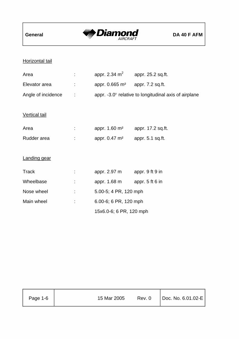
Horizontal tail
Area : appr. 2.34 m2 appr. 25.2 sq.ft.
Elevator area : appr. 0.665 m5 appr. 7.2 sq.ft.
Angle of incidence : appr. -3.0° relative to longitudinal axis of airplane
Vertical tail
Area : appr. 1.60 m5 appr. 17.2 sq.ft.
Rudder area : appr. 0.47 m5 appr. 5.1 sq.ft.
Landing gear
Track : appr. 2.97 m appr. 9 ft 9 in
Wheelbase : appr. 1.68 m appr. 5 ft 6 in
Nose wheel : 5.00-5; 4 PR, 120 mph
Main wheel : 6.00-6; 6 PR, 120 mph
15x6.0-6; 6 PR, 120 mph

DA 40 F AFM
General
Doc. No. 6.01.02-E Rev. 0 15 Mar 2005 Page 1-7
1.5 DEFINITIONS AND ABBREVIATIONS
(a) Airspeeds
CAS: Calibrated Airspeed. Indicated airspeed, corrected for installation and instrument errors. CAS equals TAS at standard atmospheric conditions at MSL.
KCAS: CAS in knots.
IAS: Indicated Airspeed as shown on an airspeed indicator.
KIAS: IAS in knots.
TAS: True Airspeed. The speed of the airplane relative to the air. TAS is CAS corrected for errors due to altitude and temperature.
vA: Maneuvering Speed. Full or abrupt control surface movement is not permissible above this speed.
vFE: Max. Flaps Extended Speed. This speed must not be exceeded with the given flap setting.
vNE: Never Exceed Speed in smooth air. This speed must not be exceeded in any operation.
General
DA 40 F AFM
Page 1-8 15 Mar 2005 Rev. 0 Doc. No. 6.01.02-E
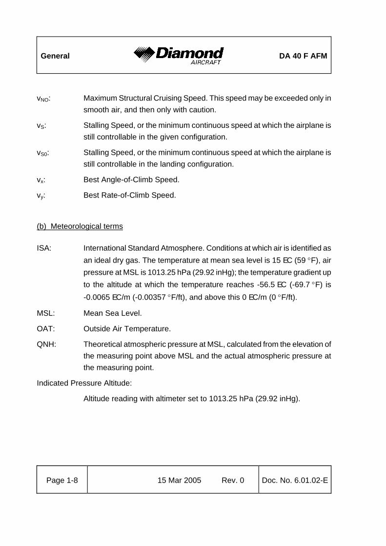
vNO: Maximum Structural Cruising Speed. This speed may be exceeded only in smooth air, and then only with caution.
vS: Stalling Speed, or the minimum continuous speed at which the airplane is still controllable in the given configuration.
vS0: Stalling Speed, or the minimum continuous speed at which the airplane is still controllable in the landing configuration.
vx: Best Angle-of-Climb Speed.
vy: Best Rate-of-Climb Speed.
(b) Meteorological terms
ISA: International Standard Atmosphere. Conditions at which air is identified as an ideal dry gas. The temperature at mean sea level is 15 EC (59 °F), air pressure at MSL is 1013.25 hPa (29.92 inHg); the temperature gradient up to the altitude at which the temperature reaches -56.5 EC (-69.7 °F) is -0.0065 EC/m (-0.00357 °F/ft), and above this 0 EC/m (0 °F/ft).
MSL: Mean Sea Level.
OAT: Outside Air Temperature.
QNH: Theoretical atmospheric pressure at MSL, calculated from the elevation of the measuring point above MSL and the actual atmospheric pressure at the measuring point.
Indicated Pressure Altitude:
Altitude reading with altimeter set to 1013.25 hPa (29.92 inHg).

DA 40 F AFM
General
Doc. No. 6.01.02-E Rev. 0 15 Mar 2005 Page 1-9
Pressure Altitude:
Altitude above MSL, indicated by a barometric altimeter which is set to 1013.25 hPa (29.92 inHg). The Pressure Altitude is the Indicated Pressure Altitude corrected for installation and instrument errors.
In this Airplane Flight Manual altimeter instrument errors are regarded as zero.
Density Altitude:
Altitude in ISA conditions at which the air density is equal to the current air density.
Wind: The wind speeds which are shown as variables in the diagrams in this manual should be regarded as headwind or downwind components of the measured wind.
Demonstrated Crosswind Component:
The speed of the crosswind component at which adequate maneuverability for take-off and landing has been demonstrated during type certification.
(c) Flight performance and flight planning
MET: Weather, weather advice.
NAV: Navigation, route planning.
COMMENT
from http://www.patprojects.org/dec98sca/patt_0.htm Pressure altitude - The altitude above the standard pressure level of 29.92" of mercury at sea level. In an airplane, we can find the pressure altitude by setting the altimeter setting to 29.92" and reading the indicated altitude. This is the altitude above the standard datum plane and is used in computer solutions for other parameters such as true airspeed (see below), true altitude, and density altitude. from http://www.weather.com/glossary/wx_glossary_p.html: PRESSURE ALTITUDE The altitude in standard atmosphere at which a given pressure will be observed. It is the indicated altitude of a pressure altimeter at an altitude setting of 29.92 inches of mercury, and is therefore the indicated altitude above the 29.92 constant pressure surface.
COMMENT
from http://www.weather.com/glossary/wx_glossary_d.html DENSITY ALTITUDE The altitude at which a given density is found in the standard atmosphere. Used in aviation, it is computed from the station pressure at takeoff and the virtual temperature at the particular altitude under consideration.

General
DA 40 F AFM
Page 1-10 15 Mar 2005 Rev. 0 Doc. No. 6.01.02-E
(d) Mass and balance
DP: Datum Plane; an imaginary vertical plane from which all horizontal distances for center of gravity calculations are measured.
Moment Arm:
The horizontal distance from the Datum Plane to the Center of Gravity of a component.
Moment: The mass of a component multiplied by its moment arm.
CG: Center of Gravity, also called 'center of mass'. Imaginary point in which the airplane mass is assumed to be concentrated for mass and balance calculations. Its distance from the Datum Plane is equal to the Center of Gravity Moment Arm.
Center of Gravity Moment Arm:
The Moment Arm which is obtained if one divides the sum of the individual moments of the airplane by its total mass.
Center of Gravity Limits:
The Center of Gravity range within which the airplane, at a given mass, must be operated.
Usable Fuel:
The quantity of fuel available for flight planning.
Unusable Fuel:
The quantity of fuel remaining in the tank which cannot be used for flight.

DA 40 F AFM
General
Doc. No. 6.01.02-E Rev. 0 15 Mar 2005 Page 1-11
Empty Mass:
The mass of the airplane including unusable fuel, all operating consumables and the maximum quantity of oil.
Useful Load:
The difference between take-off mass and empty mass.
Maximum Take-off Mass:
The maximum permissible mass for take-off.
Maximum Landing Mass:
The highest mass for landing conditions.
(e) Engine
Take-off Power:
Maximum permissible engine output power for take-off.
Maximum Continuous Power:
Maximum permissible engine output power used continuously during flight.
CHT: Cylinder Head Temperature.
EGT: Exhaust Gas Temperature.

General
DA 40 F AFM
Page 1-12 15 Mar 2005 Rev. 0 Doc. No. 6.01.02-E
(f) Designation of the circuit breakers on the instrument panel
AVIONICS:
ADF Automatic Direction Finder
AUDIO Audio Panel / Intercom
AUTOPILOT Autopilot
AVIONIC BUS Avionic Bus
DME Distance Measuring Equipment
ESSENTIAL AVIONIC Essential Avionic Bus
GPS Global Positioning System
NAV/COM Navigation/Communication Equipment
XPDR Transponder
ENGINE:
IGNITION Ignition
INST. 1 Engine Instrument VM 1000
START Starter
LIGHTING:
FLOOD Flood Light
INST. Instrument Lights
LANDING Landing Light
POSITION Position Lights
STROBE Strobe Light (= Anti Collision Light = ACL)
TAXI/MAP Taxi Light/Map Light

DA 40 F AFM
General
Doc. No. 6.01.02-E Rev. 0 15 Mar 2005 Page 1-13
SYSTEMS:
ANNUN. Annunciator Panel
DG Directional Gyro
FAN/OAT Fan/Outside Air Temperature Indicator
FLAPS Flaps
FUEL PUMP Fuel pump
HORIZON artificial horizon (attitude gyro)
PITOT HEAT Pitot Heating System
T&B Turn & Bank Indicator
ELECTRICAL:
ALT. Alternator
ALT. PROT. Alternator Protection
ALT. CONT. Alternator Control
BATT. Battery
ESSENTIAL TIE Bus Interconnection
MAIN TIE Bus Interconnection
MASTER CONTROL Master Control (avionic master switch, essential bus switch, essential avionics relay, bus interconnection relay, avionics master relay).

General
DA 40 F AFM
Page 1-14 15 Mar 2005 Rev. 0 Doc. No. 6.01.02-E
(g) Equipment
ELT: Emergency Locator Transmitter.
(h) Design change advisories
MÄM: Mandatory Design Change Advisory.
OÄM: Optional Design Change Advisory.
(i) Miscellaneous
ACG: Austro Control GmbH (Austrian Civil Airworthiness Authority).
ATC: Air Traffic Control.
CFRP: Carbon Fiber Reinforced Plastic.
GFRP: Glass Fiber Reinforced Plastic.
JAR: Joint Aviation Requirements.
JC/VP: Joint Certification/Validation Procedure.
PCA: Primary Certification Authority.

DA 40 F AFM
General
Doc. No. 6.01.02-E Rev. 0 15 Mar 2005 Page 1-15
1.6 UNITS OF MEASUREMENT
1.6.1 CONVERSION FACTORS
Dimension SI-Units US Units Conversion
Length [mm] millimeters
[m] meters
[km] kilometers
[in] inches
[ft] feet
[NM] nautical miles
[mm] / 25.4 = [in]
[m] / 0.3048 = [ft]
[km] / 1.852 = [NM]
Volume [l] liters [US gal] US gallons
[qts] US quarts
[l] / 3.7854 = [US gal]
[l] / 0.9464 = [qts]
Speed [km/h] kilometers per hour
[m/s] meters per second
[kts] knots
[mph] miles per hour
[fpm] feet per minute
[km/h] / 1.852 = [kts]
[km/h] / 1.609 = [mph]
[m/s] x 196.85 = [fpm]
Speed of rotation
[RPM] revolutions per minute --
Mass [kg] kilograms [lb] pounds [kg] x 2.2046 = [lb]
Force, weight [N] newtons [lbf] pounds force [N] x 0.2248 = [lbf]
Pressure [hPa] hecto pascals
[mbar] millibars
[bar] bars
[inHg] inches of mercury
[psi] pounds per square inch
[hPa] = [mbar]
[hPa] / 33.86 = [inHg]
[bar] x 14.504 = [psi]
Temperature [°C] degrees Celsius
[°F] degrees Fahrenheit
[°C]x1.8 + 32 = [°F]
([°F] - 32)/1.8 = [°C]

General
DA 40 F AFM
Page 1-16 15 Mar 2005 Rev. 0 Doc. No. 6.01.02-E
Dimension SI-Units US Units Conversion
Intensity of electric current
[A] ampères --
Electric charge (battery capacity)
[Ah] ampère-hours --
Electric potential
[V] volts --
Time [sec] seconds --

DA 40 F AFM
General
Doc. No. 6.01.02-E Rev. 0 15 Mar 2005 Page 1-17
1.6.2 CONVERSION CHART (LITERS / US GALLONS)
Liters US Gallons US Gallons Liters
5 1.3 1 3.8
10 2.6 2 7.6
15 4.0 4 15.1
20 5.3 6 22.7
25 6.6 8 30.3
30 7.9 10 37.9
35 9.2 12 45.4
40 10.6 14 53.0
45 11.9 16 60.6
50 13.2 18 68.1
60 15.9 20 75.7
70 18.5 22 83.3
80 21.1 24 90.9
90 23.8 26 98.4
100 26.4 28 106.0
110 29.1 30 113.6
120 31.7 32 121.1
130 34.3 34 128.7
140 37.0 36 136.3
150 39.6 38 143.8
160 42.3 40 151.4
170 44.9 45 170.3
180 47.6 50 189.3

General
DA 40 F AFM
Page 1-18 15 Mar 2005 Rev. 0 Doc. No. 6.01.02-E
1.7 THREE-VIEW DRAWING
1194
0 m
m (3
9 ft
2 in
)
8007
mm
(26
ft 3
in)

DA 40 F AFM
General
Doc. No. 6.01.02-E Rev. 0 15 Mar 2005 Page 1-19
1.8 SOURCE DOCUMENTATION
This section lists documents, manuals and other literature that were used as sources for the Airplane Flight Manual, and indicates the respective publisher. However, only the information given in the Airplane Flight Manual is valid.
1.8.1 ENGINE
Address: Textron Lycoming 652 Oliver Street WILLIAMSPORT, PA 17701, USA
Phone: +1-570-323-6181
Documents: a) Textron Lycoming Operator=s Manual, Aircraft Engines 60297-12 (Part No.)
b) Service Bulletins (SB), Service Instructions (SI); (e.g. SI 1014, SI 1070) Service Letters (SL); (e.g. SL114 (subscriptions))
1.8.2 PROPELLER
Address: Sensenich Propeller Manufacturing Co., Inc. 14 Citation Lane LITITZ, PA 17543, USA
Phone: +1-717-569-0435
Fax: +1-717-560-3725

General
DA 40 F AFM
Page 1-20 15 Mar 2005 Rev. 0 Doc. No. 6.01.02-E
1.8.3 ENGINE INSTRUMENTS
Address: VISION MICROSYSTEMS, INC. ADVANCED ELECTRONIC INSTRUMENTATION 4255 Mitchell Way BELLINGHAM, WA 98226, USA
Phone: +1-360-714-8203
Documents: 5010002 REV F, VM 1000 Owner=s Manual

DA 40 F AFM
Operating Limitations
Doc. No. 6.01.02-E Rev. 0 15 Mar 2005 Page 2-1
CHAPTER 2
OPERATING LIMITATIONS Page
2.1 INTRODUCTION...............................................................................................2-2 2.2 AIRSPEED ........................................................................................................2-3 2.3 AIRSPEED INDICATOR MARKINGS................................................................2-4 2.4 POWER-PLANT LIMITATIONS.........................................................................2-5 2.5 ENGINE INSTRUMENT MARKINGS ................................................................2-8 2.6 WARNING, CAUTION AND STATUS LIGHTS ...............................................2-10 2.7 MASS (WEIGHT) ............................................................................................2-12 2.8 CENTER OF GRAVITY...................................................................................2-13 2.9 APPROVED MANEUVERS.............................................................................2-14 2.10 MANEUVERING LOAD FACTORS...............................................................2-16 2.11 OPERATING ALTITUDE...............................................................................2-17 2.12 FLIGHT CREW..............................................................................................2-17 2.13 KINDS OF OPERATION ...............................................................................2-18 2.14 FUEL .............................................................................................................2-21 2.15 LIMITATION PLACARDS..............................................................................2-23 2.16 OTHER LIMITATIONS ..................................................................................2-29
2.16.1 TEMPERATURE.....................................................................................2-29 2.16.2 BATTERY CHARGE ...............................................................................2-29 2.16.3 EMERGENCY SWITCH..........................................................................2-29 2.16.4 OPERATION TIME OF ELECTRICAL EQUIPMENT..............................2-29 2.16.5 DOOR LOCKING DEVICE......................................................................2-29 2.16.6 ELECTRONIC EQUIPMENT...................................................................2-30 2.16.7 SMOKING...............................................................................................2-30

Operating Limitations
DA 40 F AFM
Page 2-2 15 Mar 2005 Rev. 0 Doc. No. 6.01.02-E
2.1 INTRODUCTION
Chapter 2 of this Airplane Flight Manual includes operating limitations, instrument markings, and placards necessary for the safe operation of the airplane, its power-plant, standard systems and standard equipment.
The limitations included in this Chapter are approved.
WARNING Operation of the airplane outside of the approved operating limitations is not permissible.

DA 40 F AFM
Operating Limitations
Doc. No. 6.01.02-E Rev. 0 15 Mar 2005 Page 2-3
2.2 AIRSPEED
Airspeed IAS Remarks
vAManeuvering
speed
108 KIAS
(above 980 kg / 2161 lb up to 1150 kg / 2535 lb)
94 KIAS
(780 kg / 1720 lb up to 980 kg / 2161 lb)
Do not make full or abrupt control surface movement
above this speed.
vFEMax. flaps ex-tended speed
LDG: 91 KIAS
T/O: 108 KIAS
Do not exceed these speeds with the given flap setting.
vNOMax. structural cruising speed
129 KIAS Do not exceed this speed except in smooth air, and
then only with caution.
vNE
Never exceed speed in smooth
air 178 KIAS
Do not exceed this speed in any operation.

Operating Limitations
DA 40 F AFM
Page 2-4 15 Mar 2005 Rev. 0 Doc. No. 6.01.02-E
2.3 AIRSPEED INDICATOR MARKINGS
Marking IAS Significance
White arc 49 KIAS - 91 KIAS Operating range with flaps fully ex-
tended.
Green arc 52 KIAS - 129 KIAS Normal operating range.
Yellow arc 129 KIAS - 178 KIAS >Caution= range - AOnly in smooth air@.
Red line 178 KIAS Maximum speed for all operations -
vNE.

DA 40 F AFM
Operating Limitations
Doc. No. 6.01.02-E Rev. 0 15 Mar 2005 Page 2-5
2.4 POWER-PLANT LIMITATIONS
a) Engine manufacturer : Textron Lycoming
b) Engine designation : O-360-A4M
c) RPM limitations
Max. take-off RPM : 2700 RPM
Max. continuous RPM : 2700 RPM
The engine should meet the following limits during ground check:
Throttle: IDLE.........................................600 – 800 RPM
Throttle: FULL........................................minimum 2200 RPM
NOTE The result of the ground check at full throttle is influenced by a number of environmental factors, e.g. temperature, air pressure and in particular head- or tailwind components. Headwind will cause a higher RPM than tailwind.
d) Oil pressure
Minimum (IDLE) : 25 psi / 1.72 bar
Maximum : 97 psi / 6.69 bar
Normal operating range : 55 to 95 psi / 3.8 to 6.55 bar
e) Oil quantity
Minimum : 4 qts / 3.8 l before take-off
Maximum : 8 qts / 7.6 l

Operating Limitations
DA 40 F AFM
Page 2-6 15 Mar 2005 Rev. 0 Doc. No. 6.01.02-E
f) Oil temperature
Maximum : 245 °F (118 °C)
g) Fuel pressure
Minimum : 1 psi / 0.069 bar
Maximum : 8 psi / 0.552 bar
h) Cylinder head temperature
Maximum : 500 °F (260 °C)
i) Propeller manufacturer : Sensenich
j) Propeller designation : 76EM8S10-0-63
k) Propeller diameter : 1.93 m ± 0.00 m
76 in ± 0.0 in
l) Propeller pitch (0.75 R) : 63 in
m) Oil specification:
Airplane engine oil should be used which meets SAEJ1899 (MIL-L-22851) Standard (ashless dispersant type). During the first 50 hours of operation of a new or newly overhauled engine, or after replacement of a cylinder, airplane engine oil should be used which meets SAEJ1966 (MIL-L-6082) Standard (straight mineral type). The viscosity should be selected according to the recommendation given in the following table:

DA 40 F AFM
Operating Limitations
Doc. No. 6.01.02-E Rev. 0 15 Mar 2005 Page 2-7
OAT at ground level
During the first 50 hours: SAEJ1966 / MIL-L-6082
Mineral Oil
After 50 hours: SAEJ1899 / MIL-L-22851 Ashless Dispersant Oil
All temperatures --- SAE 15-W50, SAE 20-W50
above 80 °F (above 27 °C)
SAE 60 SAE 60
above 60 °F (above 16 °C)
SAE 50 SAE 40 or SAE 50
30 °F to 90 °F (-1 °C to 32 °C)
SAE 40 SAE 40
0 °F to 90 °F (-18 °C to 32 °C)
SAE 20-W50 SAE 20-W50 or SAE 15-W50
0 °F to 70 °F (-18 °C to 21 °C)
SAE 30 SAE 30, SAE 40 or SAE 20-W40
below 10 °F (below -12 °C)
SAE 20 SAE 30 or SAE 20-W30

Operating Limitations
DA 40 F AFM
Page 2-8 15 Mar 2005 Rev. 0 Doc. No. 6.01.02-E
2.5 ENGINE INSTRUMENT MARKINGS
Engine instrument markings and their color code significance are shown in the table below:
NOTE When an indication lies in the upper or lower prohibited range, the numerical indication will begin flashing as well.
Indi-cation
Red arc/bar
= lower
prohibitedrange
Yellow arc/bar
= lower
caution range
Green arc/bar
= normal
operating range
Yellow arc/bar
= upper
caution range
Red arc/bar
= upper
prohibited range
ManifoldPressure
-- -- 13 - 30 inHg -- --
RPM -- -- 500 - 2700
RPM -- above 2700 RPM
Oil Temp.
-- -- 149 - 230 °F 231 - 245 °F above 245 °F
Cylinder Head Temp.
-- -- 150 - 475 °F 476 - 500 °F above 500 °F
Oil Pressure
below 25 psi
25 - 55 psi 56 - 95 psi 96 - 97 psi above 97 psi
Fuel Pressure
below 1 psi
1 – 2 psi 2 – 7 psi 7 – 8 psi above 8 psi
Fuel Flow
-- -- 1 - 20 US gal/hr -- above
20 US gal/hr

DA 40 F AFM
Operating Limitations
Doc. No. 6.01.02-E Rev. 0 15 Mar 2005 Page 2-9
Indi-cation
Red arc/bar
= lower
prohibited range
Yellow arc/bar
= lower
caution range
Green arc/bar
= normal
operating range
Yellow arc/bar
= upper
caution range
Red arc/bar
= upper
prohibited range
Voltage below 24.1 V
24.1 - 25 V 25.1 - 30 V 30.1 - 32 V above 32 V
Ammeter -- -- 2 - 75 A -- -- Fuel
Quantity Standard
Tank
0 US gal -- 0 - 17 US gal -- --
Fuel Quantity
Long Range Tank (if
installed)
0 US gal -- 0 – 16 US gal plus auxiliary: 3 - 9 US gal
-- --

Operating Limitations
DA 40 F AFM
Page 2-10 15 Mar 2005 Rev. 0 Doc. No. 6.01.02-E
2.6 WARNING, CAUTION AND STATUS LIGHTS
The following tables show the color and significance of the warning and caution lights on the annunciator panel.
NOTE Section 7.11 includes a detailed description of the lights on the annunciator panel.
Color and significance of the warning lights (red)
Warning lights (red) Cause
OIL PRESS oil pressure Oil pressure below 25 psi
FUEL PRESS fuel pressure Fuel pressure below 1 psi
ALTERNATOR Alternator
(generator) Alternator failure
START starter Operation of starter or failure of the starter motor
to disengage from the engine after starting
DOORS doors Front canopy and/or rear door not completely
closed and locked
TRIM FAIL trim failure Failure in the automatic trim system of the
autopilot (if installed)

DA 40 F AFM
Operating Limitations
Doc. No. 6.01.02-E Rev. 0 15 Mar 2005 Page 2-11
Color and significance of the caution lights (amber)
Caution lights (amber) Cause
LOW FUEL fuel quantity
1st caution:
fuel quantity in one tank less than 3 US gal ("1 US gal)
2nd caution:
fuel quantity in second tank less than 3 US gal ("1 US gal)
LOW VOLTS voltage On-board voltage below 24.1 V
PITOT Pitot heating Pitot heating not switched ON, or fault in the Pitot heating system

Operating Limitations
DA 40 F AFM
Page 2-12 15 Mar 2005 Rev. 0 Doc. No. 6.01.02-E
2.7 MASS (WEIGHT)
Maximum take-off mass (Normal Category) : 1150 kg 2535 lb
Maximum take-off mass (Utility Category) : 980 kg 2161 lb
Maximum landing mass : 1150 kg 2535 lb
Max. load in baggage compartment : 30 kg 66 lb
WARNING Exceeding the mass limits will lead to an overstressing of the airplane as well as to a degradation of flight characteristics and flight performance.

DA 40 F AFM
Operating Limitations
Doc. No. 6.01.02-E Rev. 0 15 Mar 2005 Page 2-13
2.8 CENTER OF GRAVITY
Datum plane
The Datum Plane (DP) is a plane which is normal to the airplane=s longitudinal axis and in front of the airplane as seen from the direction of flight. The airplane=s longitudinal axis is parallel with the upper surface of a 600:31 wedge which is placed on top of the rear fuselage in front of the vertical stabilizer. When the upper surface of the wedge is aligned horizontally, the Datum Plane is vertical. The Datum Plane is located 2.194 meters (86.38 in) forward of the most forward point of the root rib on the stub wing.
Center of gravity limitations
The center of gravity (CG) for flight conditions must lie between the following limits:
Most forward CG:
2.40 m (94.5 in) aft of DP from 780 kg to 980 kg (1720 lb to 2161 lb)
2.46 m (96.9 in) aft of DP at 1150 kg (2535 lb)
linear variation between these values
Most rearward CG:
a) Standard Tank:
2.59 m (102.0 in) aft of DP
b) Long Range Tank (if installed):
2.55 m (100.4 in) aft of DP
WARNING Exceeding the center of gravity limitations reduces the controllability and stability of the airplane.

Operating Limitations
DA 40 F AFM
Page 2-14 15 Mar 2005 Rev. 0 Doc. No. 6.01.02-E
2.9 APPROVED MANEUVERS
The airplane is certified in the Normal Category and in the Utility Category in accordance with JAR-23.
Approved maneuvers
a) Normal Category:
1) all normal flight maneuvers;
2) stalling (with the exception of dynamic stalling); and
3) lazy eights, chandelles, as well as steep turns and similar maneuvers,
in which an angle of bank of not more than 60° is attained.
CAUTION Aerobatics, spinning, and flight maneuvers with more than 60° of bank are not permitted in the Normal Category.

DA 40 F AFM
Operating Limitations
Doc. No. 6.01.02-E Rev. 0 15 Mar 2005 Page 2-15
b) Utility Category:
1) all normal flight maneuvers;
2) stalling (with the exception of dynamic stalling); and
3) lazy eights, chandelles, as well as steep turns and similar maneuvers,
in which an angle of bank of not more than 90° is attained.
CAUTION Aerobatics, spinning, and flight maneuvers with more than 90° of bank are not permitted in the Utility Category.
CAUTION The accuracy of the attitude gyro (artificial horizon) and the directional gyro is affected by the maneuvers approved under item 3 if the bank angle exceeds 60°. Such maneuvers may therefore only be flown when the above mentioned instruments are not required for the present kind of operation.

Operating Limitations
DA 40 F AFM
Page 2-16 15 Mar 2005 Rev. 0 Doc. No. 6.01.02-E
2.10 MANEUVERING LOAD FACTORS
Table of maximum structural load factors:
Normal category
at vA at vNEwith flaps in T/O or LDG position
Positive 3.8 3.8 2.0
Negative -1.52 0
Utility category
at vA at vNEwith flaps in T/O or LDG position
Positive 4.4 4.4 2.0
Negative -1.76 -1.0
WARNING Exceeding the maximum load factors will lead to an overstressing of the airplane.

DA 40 F AFM
Operating Limitations
Doc. No. 6.01.02-E Rev. 0 15 Mar 2005 Page 2-17
2.11 OPERATING ALTITUDE
The maximum demonstrated operating altitude is 16,400 ft (5,000 meters).
The maximum approved operating altitude for US registered airplanes is 14,000 ft MSL unless an approved supplemental oxygen system is installed.
2.12 FLIGHT CREW
Minimum crew number : 1 (one person)
Maximum number of occupants
Normal Category : 4 (four persons)
Utility Category : 2 (two persons), both of whom must sit in front

Operating Limitations
DA 40 F AFM
Page 2-18 15 Mar 2005 Rev. 0 Doc. No. 6.01.02-E
2.13 KINDS OF OPERATION Provided that national operational requirements are met, the following kinds of operation are approved:
* daytime flights according to Visual Flight Rules (VFR)
* with the appropriate equipment: night flights according to Visual Flight Rules (VFR)
* with the appropriate equipment: flights according to Instrument Flight Rules (IFR)
Flights into known or forecast icing conditions are prohibited. Flights into known thunderstorms are prohibited.
Minimum operational equipment (serviceable)
The following table lists the minimum serviceable equipment required by JAR-23. Additional minimum equipment for the intended operation may be required by national operating rules and also depends on the route to be flown.
for daytime VFR flights
in addition for night VFR flights
in addition for IFR flights
Flight and naviga-tion instru-ments
* airspeed indicator * altimeter * magnetic compass
* vertical speed indicator (VSI) * attitude gyro (artificial horizon) * turn & bank indicator * directional gyro * OAT indicator * chronometer with indication of hours, minutes, and seconds * VHF radio (COM) with speaker and microphone * VOR receiver * transponder (XPDR), mode A and mode C * 1 headset
* second VHF radio (COM) * VOR-LOC-GP receiver * marker beacon receiver

DA 40 F AFM
Operating Limitations
Doc. No. 6.01.02-E Rev. 0 15 Mar 2005 Page 2-19
for daytime VFR flights
in addition for night VFR flights
in addition for IFR flights
engine instru-ments
* fuel indicators * integrated engine instrument * annunciator panel (all lights, see 2.6)
* ammeter (included in VM 1000) * voltmeter (included in VM 1000)
lighting * position lights * strobe lights (anti collision lights) * landing light * instrument lighting * flood light * flashlight
other opera-tional
minimum equip-ment
* stall warning system * fuel quantity measuring device (see 7.10) * safety belts for each occupied seat * airplane flight manual * CO Detector/ Alarm
* Pitot heating system * alternate static valve * essential bus
* emergency battery

Operating Limitations
DA 40 F AFM
Page 2-20 15 Mar 2005 Rev. 0 Doc. No. 6.01.02-E
NOTE A list of approved equipment can be found in Chapter 6.
NOTE For the upgrade of an airplane for Night VFR or IFR operation it is not sufficient to install the required equipment. The retrofit must be carried out in accordance with the requirements of the manufacturer (refer to Service Bulletins) and the national airworthiness authority. Any additional equipment (equipment which is not listed in the Equipment List in Section 6.5) must also be approved for the intended kind of operation by the national airworthiness authority.

DA 40 F AFM
Operating Limitations
Doc. No. 6.01.02-E Rev. 0 15 Mar 2005 Page 2-21
2.14 FUEL
a) Standard Tank:
Fuel grade : AVGAS 100LL
Fuel quantity : Total fuel quantity : 2 x 20.6 US gal (approx. 156 liters)
Unusable fuel : 2 x 0.5 US gal (approx. 3.8 liters)
Max. indicated fuel quantity : 17 US gal (approx. 64 l) per tank
Max. permissible difference
between right and left tank : 10 US gal (approx. 38 liters)
CAUTION If a fuel indicator shows 17 US gal, then 20 US gal must be assumed for the calculation of the difference between right and left tank.

Operating Limitations
DA 40 F AFM
Page 2-22 15 Mar 2005 Rev. 0 Doc. No. 6.01.02-E
b) Long Range Tank (if installed):
Fuel quantity :
Total fuel quantity : 2 x 25.5 US gal (approx. 193 liters)
Unusable fuel : 2 x 0.5 US gal (approx. 3.8 liters)
Max. indicated fuel quantity : 16 US gal (approx. 61 liters) per tank
Indicated auxiliary fuel quantity: 3 to 9 US gal (approx. 11 to 34 liters)
per tank
Max. permissible difference
between right and left tank : 8 US gal (approx. 30.3 liters)
CAUTION If a fuel indicator shows 16 US gal and the aux. fuel indicator shows 0 US gal for the same fuel tank, then 16 or 19 US gal must be assumed for the calculation of the difference between right and left tank, whichever leads to the greater imbalance.

DA 40 F AFM
Operating Limitations
Doc. No. 6.01.02-E Rev. 0 15 Mar 2005 Page 2-23
2.15 LIMITATION PLACARDS
All limitation placards are shown below. A list of all placards is included in the Airplane Maintenance Manual (Doc. No. 6.02.01), Chapter 11.
On the instrument panel:
Maneuvering speed:
vA = 108 KIAS (above 980 up to 1150 kg / above 2161 up to 2535 lb)
vA = 94 KIAS (780 to 980 kg / 1720 to 2161 lb)
This airplane may only be operated in accordance with the Airplane Flight Manual. It can be operated in the ”Normal” and “Utility” categories in non-icing conditions. Provided that national operational requirements are met and the appropriate equipment is installed, this airplane is approved for the following kinds of operation: day VFR, night VFR and IFR. All aerobatic maneuvers including spinning are prohibited. For further operational limitations refer to the Airplane Flight Manual.
No smoking.
Next to the carbon monoxide detector:

Operating Limitations
DA 40 F AFM
Page 2-24 15 Mar 2005 Rev. 0 Doc. No. 6.01.02-E
Next to each of the two fuel filler necks:
a) Standard Tank:
AVGAS 100LL76 l / 20 US gal.
b) Long Range Tank (if installed):
AVGAS 100LL94 l / 25 US gal.
In the cowling, on the door for the oil filler neck:
OIL SAE 15W50
ashless dispersant aviation
grade oil (SAE Standard J-1899)
or see AFM Chapter 2
Min./Max.: 4/8 qts
Recommended: 6 qts

DA 40 F AFM
Operating Limitations
Doc. No. 6.01.02-E Rev. 0 15 Mar 2005 Page 2-25
Next to the flap selector switch:
m a x .1 0 8 K IA S
m a x . 9 1 K IA S
Next to the essential bus switch (if installed):
Ess. Bus NOT for normal operation. See AFM.
Next to the fuel quantity indication:
a) Standard Tank:
max. indicated fuel quantity: 17 US gal
left and right tank max. 10 US gal difference For use of max. tank capacity see AFM

Operating Limitations
DA 40 F AFM
Page 2-26 15 Mar 2005 Rev. 0 Doc. No. 6.01.02-E
b) Long Range Tank (if installed):
Fuel qty. indication: 16 + 9 US galmax. difference LH/RH tank: 8 US gal
AUX FUEL QTY switch for LH/RH auxiliary fuel quantityNOTE: See AFM for more information on AUX FUEL
Fuel qty. indication: 16 + 9 US galmax. difference LH/RH tank: 8 US gal
AUX FUEL QTY switch for LH/RH auxiliary fuel quantityNOTE: See AFM for more information on AUX FUEL
On the fuel tank selector:
a) Standard Tank:
Fu e l
S e l e c t o r
LEFT
OFF
20 US gal. 20 US gal.76 l 76 l

DA 40 F AFM
Operating Limitations
Doc. No. 6.01.02-E Rev. 0 15 Mar 2005 Page 2-27
b) Long Range Tank (if installed):
Fu e l
S e l e c t o r
LEFT
OFF
25 US gal. 25 US gal.94 l 94 l

Operating Limitations
DA 40 F AFM
Page 2-28
In the cockpit, on the left fuselage sidewall (if alternate static valve is installed):
6630 m
Next to the bagg
Beside the door
(if installed):
15 Mar 2005 Rev. 0 Doc. No. 6.01.02-E
lbskg /ax.
age compartment:
EMERGENCY EXIT: The keylock must be unlocked during flight
locking device

DA 40 F AFM
Operating Limitations
Doc. No. 6.01.02-E Rev. 0 15 Mar 2005 Page 2-29
2.16 OTHER LIMITATIONS
2.16.1 TEMPERATURE
The airplane may only be operated when its temperature is not less than -40 °C (-40 °F).
CAUTION For cold weather starting of the engine refer to the latest instructions given by the engine manufacturer.
2.16.2 BATTERY CHARGE
Taking off for a Night VFR or IFR flight with an empty battery is not permitted.
The use of an external power supply for engine starting with an empty airplane battery is not permitted if the subsequent flight is intended to be an IFR flight. In this case the airplane battery must first be charged.
2.16.3 EMERGENCY SWITCH
IFR flights are not permitted when the seal on the emergency switch is broken.
2.16.4 OPERATION TIME OF ELECTRICAL EQUIPMENT
Following an alternator failure and with the Essential Bus (if installed) switched ON, it can be expected that the systems listed under 3.7.2 FAILURES IN THE ELECTRICAL SYSTEM are supplied with power for half an hour. After this, electrical power is available for the attitude gyro (artificial horizon) and flood light for another 1.5 hours when the emergency power pack (if installed) is used.
2.16.5 DOOR LOCKING DEVICE
The canopy and the passenger door must not be blocked by the door locking device during operation of the airplane.

Operating Limitations
DA 40 F AFM
Page 2-30 15 Mar 2005 Rev. 0 Doc. No. 6.01.02-E
2.16.6 ELECTRONIC EQUIPMENT
The use and switching on of electronic equipment other than that which is part of the equipment of the airplane is not permitted, as it could lead to interference with the airplane=s avionics.
Examples of undesirable items of equipment are:
- Mobile telephones
- Remote radio controls
- Video screens employing CRTs
- Minidisc recorders when in the record mode.
This list is not exhaustive.
The use of laptop computers, including those with CD-ROM drives, CD and minidisc players in the replay mode, cassette players and video cameras is permitted. All this equipment however should be switched off for take-off and landing.
2.16.7 SMOKING
Smoking in the airplane is not permitted.

DA 40 F AFM
EmergencyProcedures
Doc. No. 6.01.02-E Rev. 0 15 Mar 2005 Page 3-1
CHAPTER 3
EMERGENCY PROCEDURES Page
3.1 INTRODUCTION...............................................................................................3-3 3.1.1 GENERAL...................................................................................................3-3 3.1.2 CERTAIN AIRSPEEDS IN EMERGENCIES...............................................3-4
3.2 ENGINE PROBLEMS........................................................................................3-5 3.2.1 ENGINE PROBLEMS ON THE GROUND..................................................3-5 3.2.2 ENGINE PROBLEMS DURING TAKE-OFF ...............................................3-6 3.2.3 ENGINE PROBLEMS IN FLIGHT...............................................................3-8 3.2.4 RESTARTING THE ENGINE WITH WINDMILLING PROPELLER...........3-14 3.2.5 DEFECTIVE ENGINE CONTROLS ..........................................................3-15 3.2.6 RESTARTING THE ENGINE WITH STATIONARY PROPELLER............3-16
3.3 SMOKE AND FIRE..........................................................................................3-18 3.3.1 SMOKE AND FIRE ON THE GROUND....................................................3-18 3.3.2 SMOKE AND FIRE DURING TAKE-OFF .................................................3-20 3.3.3 SMOKE AND FIRE IN FLIGHT.................................................................3-22
3.4 GLIDING..........................................................................................................3-24 3.5 EMERGENCY LANDINGS..............................................................................3-25
3.5.1 EMERGENCY LANDING WITH ENGINE OFF.........................................3-25 3.5.2 LANDING WITH A DEFECTIVE TIRE ON THE MAIN LANDING GEAR..3-27 3.5.3 LANDING WITH DEFECTIVE BRAKES ...................................................3-28
3.6 RECOVERY FROM AN UNINTENTIONAL SPIN............................................3-29 3.7 OTHER EMERGENCIES ................................................................................3-30
3.7.1 ICING........................................................................................................3-30 3.7.2 FAILURES IN THE ELECTRICAL SYSTEM.............................................3-31 3.7.3 SUSPICION OF CARBON MONOXIDE CONTAMINATION ....................3-35

Emergency Procedures
DA 40 F AFM
Page 3-2 15 Mar 2005 Rev. 0 Doc. No. 6.01.02-E
NOTE Procedures for uncritical system faults are given in Chapter 4B ABNORMAL OPERATING PROCEDURES.
DA 40 F AFM
EmergencyProcedures
Doc. No. 6.01.02-E Rev. 0 15 Mar 2005 Page 3-3
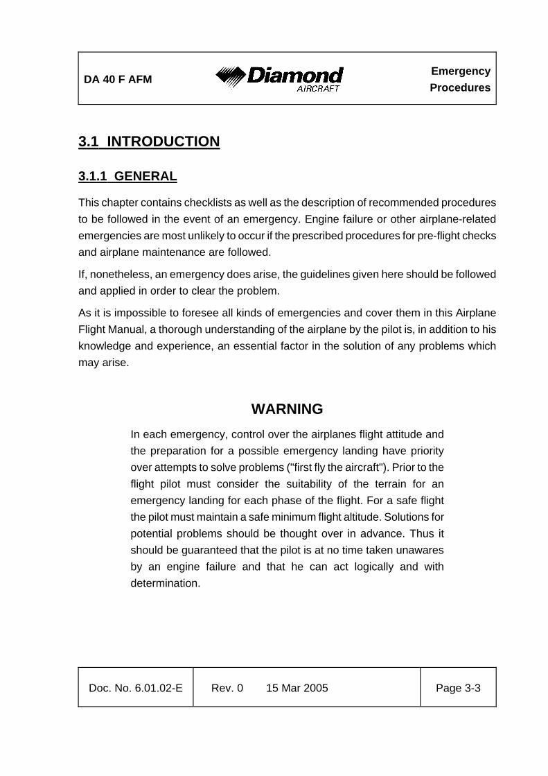
3.1 INTRODUCTION
3.1.1 GENERAL
This chapter contains checklists as well as the description of recommended procedures to be followed in the event of an emergency. Engine failure or other airplane-related emergencies are most unlikely to occur if the prescribed procedures for pre-flight checks and airplane maintenance are followed.
If, nonetheless, an emergency does arise, the guidelines given here should be followed and applied in order to clear the problem.
As it is impossible to foresee all kinds of emergencies and cover them in this Airplane Flight Manual, a thorough understanding of the airplane by the pilot is, in addition to his knowledge and experience, an essential factor in the solution of any problems which may arise.
WARNING In each emergency, control over the airplanes flight attitude and the preparation for a possible emergency landing have priority over attempts to solve problems ("first fly the aircraft"). Prior to the flight pilot must consider the suitability of the terrain for an emergency landing for each phase of the flight. For a safe flight the pilot must maintain a safe minimum flight altitude. Solutions for potential problems should be thought over in advance. Thus it should be guaranteed that the pilot is at no time taken unawares by an engine failure and that he can act logically and with determination.

Emergency Procedures
DA 40 F AFM
Page 3-4 15 Mar 2005 Rev. 0 Doc. No. 6.01.02-E
3.1.2 CERTAIN AIRSPEEDS IN EMERGENCIES
Event 850 kg
1874 lb
1000 kg
2205 lb
1150 kg
2535 lb
Engine failure after take-off
(Flaps T/O) 59 KIAS 66 KIAS 72 KIAS
Airspeed for best glide angle (Flaps UP)
60 KIAS 68 KIAS 73 KIAS
Flaps UP 60 KIAS 68 KIAS 73 KIAS
Flaps T/O 59 KIAS 66 KIAS 72 KIAS Emergency landing with engine off Flaps LDG 58 KIAS 63 KIAS 71 KIAS

DA 40 F AFM
EmergencyProcedures
Doc. No. 6.01.02-E Rev. 0 15 Mar 2005 Page 3-5
3.2 ENGINE PROBLEMS
NOTE For carburetor fire situations refer to section 3.3.
3.2.1 ENGINE PROBLEMS ON THE GROUND
1. Throttle ..................................................IDLE
2. Brakes ...................................................as required
3. Engine ...................................................switch off, if considered necessary;
otherwise establish the cause of the
problem and re-establish engine
performance
CAUTION If the oil pressure is below the green sector, the engine must be switched off immediately.
WARNING If the problem cannot be cleared, the airplane must not be flown. Unscheduled maintenance is necessary.

Emergency Procedures
DA 40 F AFM
Page 3-6 15 Mar 2005 Rev. 0 Doc. No. 6.01.02-E
3.2.2 ENGINE PROBLEMS DURING TAKE-OFF
(a) Take-off can still be abandoned (sufficient runway length available)
land straight ahead:
1. Throttle.................................................. IDLE
on the ground:
2. Brakes................................................... as required
CAUTION If sufficient time remains, the risk of fire in the event of a collision can be reduced as follows:
Fuel tank selector......................OFF
Mixture control lever..................LEAN - shut engine off
Ignition switch ...........................OFF
Battery / Alternator switch .........OFF

DA 40 F AFM
EmergencyProcedures
Doc. No. 6.01.02-E Rev. 0 15 Mar 2005 Page 3-7
(b) Take-off can no longer be abandoned
1. Airspeed ................................................72 KIAS (1150 kg, 2535 lb)
66 KIAS (1000 kg, 2205 lb)
59 KIAS (850 kg, 1874 lb)
WARNING If, in the event of an engine problem occurring during take-off, the take-off cannot be abandoned and a safe height has not been reached, then a straight-ahead emergency landing should be carried out. Turning back can be fatal.
if time allows the following procedure can be carried out in order to re-establish engine power:
2. Fuel tank selector ..................................check selected tank
3. Electrical fuel pump ...............................check ON
4. Ignition switch ........................................check BOTH
5. Throttle ..................................................check MAX PWR / fully forward
6. Mixture control lever ..............................check RICH (leaner above 5000 ft)
7. Carburetor heat......................................ON
WARNING If the problem does not clear itself immediately, and the engine is no longer producing sufficient power, then an emergency landing must be carried out.

Emergency Procedures
DA 40 F AFM
Page 3-8 15 Mar 2005 Rev. 0 Doc. No. 6.01.02-E
3.2.3 ENGINE PROBLEMS IN FLIGHT
(a) Engine running roughly
WARNING An engine which is running very roughly can lead to the loss of the propeller. Only if there is no other alternative should a rough running engine remain switched on.
1. Airspeed................................................ 73 KIAS (1150 kg, 2535 lb)
68 KIAS (1000 kg, 2205 lb)
60 KIAS (850 kg, 1874 lb)
2. Electrical fuel pump............................... check ON
3. Fuel tank selector.................................. check selected tank
4. Engine instruments ............................... check
5. Throttle.................................................. check
6. Mixture control lever.............................. set for smooth running
7. Carburetor heat ..................................... ON
8. Ignition switch........................................ check BOTH
9. Throttle / Mixture ................................... try various settings

DA 40 F AFM
EmergencyProcedures
Doc. No. 6.01.02-E Rev. 0 15 Mar 2005 Page 3-9
CAUTION Carburetor icing:
Under certain moist atmospheric conditions it is possible for ice to form in the induction system, even in summer weather.
This is due to the high air velocity through the carburetor venturi, its liquid water content and the absorption of heat from this air by vaporization of fuel.
To avoid this, a carburetor preheat system is provided in order to replace the heat lost by vaporization. The Carburetor Heat should be set fully ON when carburetor icing is encountered (reduction of engine power, rough running engine etc.) Be aware of power reduction caused by switching ON the carburetor heat.
Adjust the mixture for maximum smoothness.
WARNING If the problem does not clear itself immediately, and the engine is no longer producing sufficient power, then an emergency landing should be carried out.

Emergency Procedures
DA 40 F AFM
Page 3-10 15 Mar 2005 Rev. 0 Doc. No. 6.01.02-E
(b) Low oil pressure
1. Oil pressure........................................... check
2. Throttle.................................................. reduce as far as possible
3. Oil temperature ..................................... check
4. Cylinder head temperature.................... check
Land as soon as possible.
Be prepared for an engine failure.
If necessary carry out an emergency landing in accordance with 3.5.1 EMERGENCY LANDING WITH ENGINE OFF.
CAUTION In case of vibration, loss of oil, possibly unusual metallic noise and smoke the engine should be shut down immediately.
(c) High oil pressure
1. Oil temperature ..................................... check
NOTE If the oil temperature is normal, the oil pressure sensor might be faulty. Continue flight and have the airplane inspected before the the next flight.

DA 40 F AFM
EmergencyProcedures
Doc. No. 6.01.02-E Rev. 0 15 Mar 2005 Page 3-11
(d) High oil temperature
1. Oil pressure ...........................................check
If oil pressure is low: proceed acc. to 3.2.3 (b) Low oil pressure and prepare for forced landing.
If oil pressure is normal:
2. Cylinder head temperature ....................check
3. Mixture...................................................check, enrich if necessary
4. Throttle ..................................................reduce
5. Airspeed ................................................increase
Land as soon as practicable.
NOTE Have the airplane inspected before next flight.

Emergency Procedures
DA 40 F AFM
Page 3-12 15 Mar 2005 Rev. 0 Doc. No. 6.01.02-E
(e) High cylinder head temperature
1. Mixture .................................................. check and adjust if necessary
2. Oil pressure........................................... check
If oil pressure is low:
Proceed acc. to 3.2.3 (b) Low oil pressure.
If oil pressure is normal:
3. Mixture .................................................. check, enrich if necessary
4. Throttle.................................................. reduce
5. Airspeed................................................ increase
(f) Loss of RPM
1. Electrical fuel pump............................... check ON
2. Fuel tank selector.................................. check
3. Friction adjuster of throttle quadrant...... check sufficiently tight

DA 40 F AFM
EmergencyProcedures
Doc. No. 6.01.02-E Rev. 0 15 Mar 2005 Page 3-13
(g) High fuel flow
1. Fuel pressure.........................................check
Low fuel pressure indicates a possible leak in the fuel system:
2. Fuel quantity ..........................................check and monitor
3. Power setting.........................................check
Land as soon as practicable. Consider the reduced range and endurance due to possible loss of fuel.
NOTE Have the airplane inspected before next flight.
(h) Low fuel pressure
1. Electric fuel pump ..................................ON
2. Fuel quantity ..........................................check
3. Fuel selector ..........................................check
4. Mixture...................................................check, adjust if necessary
Land as soon as practicable. Prepare for engine failure (see: 3.5.1 EMERGENCY LANDING WITH ENGINE OFF).

Emergency Procedures
DA 40 F AFM
Page 3-14 15 Mar 2005 Rev. 0 Doc. No. 6.01.02-E
3.2.4 RESTARTING THE ENGINE WITH WINDMILLING PROPELLER
NOTE Restarting the engine has been demonstrated at all airspeeds above 70 KIAS up to 130 KIAS and up to 11000 ft Pressure Altitude.
NOTE As long as an airspeed of at least 65 KIAS is maintained, and there is no major engine failure, the propeller will continue to windmill.
1. Airspeed................................................ 70 – 130 KIAS
2. Fuel tank selector.................................. fullest tank
3. Ignition switch........................................ check BOTH
4. Mixture control lever.............................. check appropriate position
5. Electrical fuel pump............................... check ON
6. Carburetor heat ..................................... ON
if engine does not start:
7. Mixture control lever.............................. LEAN
8. Mixture control lever.............................. push forward slowly
until engine starts
NOTE If it is not possible to start the engine:
- adopt glide configuration as in 3.4 - GLIDING
- carry out emergency landing as in 3.5.1 - EMERGENCY LANDING WITH ENGINE OFF

DA 40 F AFM
EmergencyProcedures
Doc. No. 6.01.02-E Rev. 0 15 Mar 2005 Page 3-15
3.2.5 DEFECTIVE ENGINE CONTROLS
(a) Defective mixture control cable
Flight and Landing:
1. Maintain altitude to the nearest airfield.
2. During descent, test the reaction of the engine to a higher power setting. A lean mixture can lead to engine roughness and a loss of power. The landing approach must be planned accordingly.
CAUTION A go-around may become impossible with the remaining power.
Engine shut-down:
1. Parking brake.........................................set
2. Engine instruments ................................check
3. Avionics master switch ..........................OFF
4. All electrical equipment..........................OFF
5. Throttle ..................................................IDLE
6. Ignition switch ........................................OFF
7. Battery / Alternator switch......................OFF
CAUTION This procedure leaves the engine in a „hot prop“ status. Do not touch / rotate the propeller blades by hand. This might lead to serious injury or death.

Emergency Procedures
DA 40 F AFM
Page 3-16 15 Mar 2005 Rev. 0 Doc. No. 6.01.02-E
(b) Defective throttle control cable
Sufficient engine power available to continue flight:
1. Approach the nearest airfield, control engine power with RPM lever.
2. Perform a landing with the engine shut down.
Insufficient engine power available to continue flight:
1. Carry out an emergency landing as in 3.5.1 - EMERGENCY LANDING WITH ENGINE OFF.
3.2.6 RESTARTING THE ENGINE WITH STATIONARY PROPELLER
NOTE Restarting the engine has been demonstrated at airspeeds above 70 KIAS up to 75 KIAS and up to 10000 ft Pressure Altitude.
1. Airspeed................................................ 70 - 80 KIAS
2. Electrical equipment.............................. OFF
3. Avionics master switch.......................... OFF
4. Master switch (BAT).............................. check ON
5. Mixture control lever.............................. check
6. Fuel tank selector.................................. check
7. Electrical fuel pump............................... check ON
8. Carburetor heat ..................................... ON
9. Ignition switch........................................ START

DA 40 F AFM
EmergencyProcedures
Doc. No. 6.01.02-E Rev. 0 15 Mar 2005 Page 3-17
NOTE By increasing the airspeed above approximately 130 KIAS, the propeller will begin to rotate and the engine can thus be started. The ignition switch should be set at BOTH (see 3.2.4 RESTARTING THE ENGINE WITH WINDMILLING PROPELLER). An altitude loss of at least 1000 ft (300 meters) must be allowed for.
If it is not possible to start the engine:
- adopt glide configuration as in 3.4 - GLIDING
- carry out an emergency landing as in 3.5.1 - EMERGENCY LANDING WITH ENGINE OFF
CAUTION Engine restart following an engine fire should only be attempted if it is unlikely that a safe emergency landing can be made. It must be expected that engine restart is impossible after an engine fire.

Emergency Procedures
DA 40 F AFM
Page 3-18 15 Mar 2005 Rev. 0 Doc. No. 6.01.02-E
3.3 SMOKE AND FIRE
3.3.1 SMOKE AND FIRE ON THE GROUND
(a) Engine / carburetor fire when starting on the ground
1. Starter ................................................... crank engine
if engine fires:
2. Throttle.................................................. set RPM to1800 for 4 minutes
3. Cabin heat............................................. OFF
4. Brakes................................................... apply
if engine does not fire:
5. Mixture .................................................. LEAN
6. Throttle.................................................. FULL
7. Electrical fuel pump............................... OFF
8. Fuel selector.......................................... OFF
9. Battery / Alternator switch ..................... OFF
when the engine has stopped:
10. Ignition switch........................................ OFF
11. Canopy.................................................. open
12. Airplane................................................. evacuate immediately

DA 40 F AFM
EmergencyProcedures
Doc. No. 6.01.02-E Rev. 0 15 Mar 2005 Page 3-19
(b) Electrical fire with smoke on the ground
1. Battery / Alternator switch......................OFF
2. Brakes ...................................................apply
if the engine is running:
3. Throttle ..................................................IDLE
4. Mixture control lever ..............................LEAN - shut off engine
when the engine has stopped:
5. Ignition switch ........................................OFF
6. Canopy ..................................................open
7. Airplane .................................................evacuate immediately
CAUTION Unscheduled maintenance is necessary.

Emergency Procedures
DA 40 F AFM
Page 3-20 15 Mar 2005 Rev. 0 Doc. No. 6.01.02-E
3.3.2 SMOKE AND FIRE DURING TAKE-OFF
(a) If take-off can still be abandoned
1. Throttle.................................................. IDLE
2. Cabin heat............................................. OFF
3. Brakes................................................... apply - bring the airplane to a stop
4. After stopping ........................................ proceed as in 3.3.1 - SMOKE AND
FIRE ON THE GROUND
(b) If take-off cannot be abandoned
1. Cabin heat............................................. OFF
2. If possible, fly along a short-cut traffic circuit and land on the airfield.
WARNING If, in the event of an engine problem occurring during take-off, the take-off can no longer be abandoned and a safe height has not been reached, then a straight-ahead emergency landing should be carried out. Turning back can be fatal.
3. Airspeed for best glide angle................. 73 KIAS (1150 kg, 2535 lb)
68 KIAS (1000 kg, 2205 lb)
60 KIAS (850 kg, 1874 lb)

DA 40 F AFM
EmergencyProcedures
Doc. No. 6.01.02-E Rev. 0 15 Mar 2005 Page 3-21
after climbing to a height from which the selected landing area can be reached safely:
4. Fuel tank selector ..................................OFF
5. Electrical fuel pump ...............................OFF
6. Cabin heat .............................................OFF
7. Battery / Alternator switch......................OFF
8. Emergency windows..............................open if required
9. Carry out emergency landing with engine off. Allow for increased landing distance due to the flap position.
CAUTION In case of extreme smoke development, the front canopy may be unlatched during flight. This allows it to partially open, in order to improve ventilation. The canopy will remain open in this position. Flight characteristics will not be affected significantly.
CAUTION Unscheduled maintenance is necessary.

Emergency Procedures
DA 40 F AFM
Page 3-22 15 Mar 2005 Rev. 0 Doc. No. 6.01.02-E
3.3.3 SMOKE AND FIRE IN FLIGHT
(a) Engine fire in flight
1. Cabin heat......................................................OFF
2. Select appropriate emergency landing field.
when it seems certain that the landing field will be reached:
3. Fuel tank selector...........................................OFF
4. Throttle...........................................................MAX PWR
5. Electrical fuel pump........................................OFF
6. Master switch / Battery+Alternator switch ......ON
7. Emergency windows ......................................open if required
8. Carry out an emergency landing with engine off.
9. Evacuate after stand - still
CAUTION In case of extreme smoke development, the front canopy may be unlatched during flight. This allows it to partially open, in order to improve ventilation. The canopy will remain open in this position. Flight characteristics will not be affected significantly.

DA 40 F AFM
EmergencyProcedures
Doc. No. 6.01.02-E Rev. 0 15 Mar 2005 Page 3-23
(b) Electrical fire with smoke in flight
1. Emergency switch........................................ ON if installed
2. Master switch / Battery+Alternator switch .... OFF
3. Cabin heat ................................................... OFF
4. Emergency windows.................................... open if required
5. Land at an appropriate airfield as soon as possible
CAUTION Switching OFF the master switch (BAT) will lead to total failure of all electronic and electric equipment. Also affected are - if installed - the attitude gyro (artificial horizon) and the directional gyro.
However, by switching the emergency switch ON (only installed in the IFR model), the emergency battery will supply power to the attitude gyro (artificial horizon) and the flood light.
In case of extreme smoke development, the front canopy may be unlatched during flight. This allows it to partially open, in order to improve ventilation. The canopy will remain open in this position. Flight characteristics will not be affected significantly.

Emergency Procedures
DA 40 F AFM
Page 3-24 15 Mar 2005 Rev. 0 Doc. No. 6.01.02-E
3.4 GLIDING
1. Flaps ..................................................... UP
2. Airspeed for best glide angle (flaps UP) 73 KIAS (1150 kg, 2535 lb)
68 KIAS (1000 kg, 2205 lb)
60 KIAS (850 kg, 1874 lb)
NOTE The glide ratio is 8.9; i.e., for every 1000 ft (305 meters) of altitude loss the maximum horizontal distance traveled in still air is 1.46 NM (2.71 km). During this time the propeller will continue to windmill.

DA 40 F AFM
EmergencyProcedures
Doc. No. 6.01.02-E Rev. 0 15 Mar 2005 Page 3-25
3.5 EMERGENCY LANDINGS
3.5.1 EMERGENCY LANDING WITH ENGINE OFF
1. Select a suitable landing area. If no level landing area is available, a landing on an upward slope should be attempted.
2. Consider the wind.
3. Approach: If possible, fly a short-cut rectangular circuit. On the downwind leg of the circuit the landing area should be inspected for obstacles from a suitable height. The degree of offset at each part of the circuit will allow the wind speed and direction to be assessed.
4. Airspeed for best glide angle (flaps UP) 73 KIAS (1150 kg, 2535 lb)
68 KIAS (1000 kg, 2205 lb)
60 KIAS (850 kg, 1874 lb)
5. ATC .......................................................advise, if time allows
6. Fuel tank selector ..................................OFF
when it is certain that the landing field will be reached:
7. Flaps......................................................LDG
8. Safety harnesses ...................................tighten

Emergency Procedures
DA 40 F AFM
Page 3-26 15 Mar 2005 Rev. 0 Doc. No. 6.01.02-E
CAUTION If sufficient time remains, the risk of fire in the event of a collision with obstacles can be reduced as follows:
Ignition switch ..............................................OFF
Master switch / Battery+Alternator switch ....OFF
9. Touchdown............................................ with the lowest possible airspeed

DA 40 F AFM
EmergencyProcedures
Doc. No. 6.01.02-E Rev. 0 15 Mar 2005 Page 3-27
3.5.2 LANDING WITH A DEFECTIVE TIRE ON THE MAIN LANDING GEAR
CAUTION A defective (e.g. burst) tire is not usually easy to detect. The damage normally occurs during take-off or landing, and is hardly noticeable during fast taxiing. It is only during the roll-out after landing or at lower taxiing speeds that a tendency to swerve occurs. Rapid and determined action is then required.
1. Advise ATC.
2. Land the airplane at the edge of the runway that is located on the side of the intact tire, so that changes in direction which must be expected during roll-out due to the braking action of the defective tire can be corrected on the runway.
3. Land with one wing low. The wing on the side of the intact tire should be held low.
4. Direction should be maintained using the rudder. This should be supported by use of the brake. It is possible that the brake must be applied strongly - if necessary to the point where the wheel locks. The wide track of the landing gear will prevent the airplane from tipping over a wide speed range. There is no pronounced tendency to tip even when skidding.

Emergency Procedures
DA 40 F AFM
Page 3-28 15 Mar 2005 Rev. 0 Doc. No. 6.01.02-E
3.5.3 LANDING WITH DEFECTIVE BRAKES
In general, a landing on grass is recommended in order to reduce the landing run by virtue of the greater rolling resistance.
CAUTION If sufficient time remains, the risk of fire in the event of a collision can be reduced as follows:
Fuel tank selector.......................................OFF
Mixture control lever...................................LEAN - shut off engine
Ignition switch ............................................OFF
Master switch / Battery+Alternator switch ..OFF

DA 40 F AFM
EmergencyProcedures
Doc. No. 6.01.02-E Rev. 0 15 Mar 2005 Page 3-29
3.6 RECOVERY FROM AN UNINTENTIONAL SPIN
CAUTION Steps 1 to 4 must be carried out immediately and simultaneously.
1. Throttle ..................................................IDLE
2. Rudder...................................................full deflection against
direction of spin
3. Elevator (control stick) ...........................fully forward
4. Ailerons..................................................neutral
5. Flaps......................................................UP
when rotation has stopped:
6. Rudder...................................................neutral
7. Elevator (control stick) ...........................pull carefully
8. Recover the airplane from a descent into a normal flight attitude. In so doing, do not exceed the 'never exceed speed', vNE.

Emergency Procedures
DA 40 F AFM
Page 3-30 15 Mar 2005 Rev. 0 Doc. No. 6.01.02-E
3.7 OTHER EMERGENCIES
3.7.1 ICING
Unintentional flight into icing conditions
1. Leave the icing area (by changing altitude or turning back, in order to reach zones with a higher ambient temperature).
2. Pitot heating .......................................... ON
3. Cabin heat............................................. ON
4. Air distributor lever ................................ • (up)
5. RPM ...................................................... increase, in order to prevent ice
build-up on the propeller blades
6. Carburetor heat ..................................... ON
7. Emergency windows ............................. open if required
CAUTION Ice build-up increases the stalling speed.
8. ATC....................................................... advise if an emergency is expected
CAUTION When the Pitot heating fails, and the alternate static valve is installed:
Alternate static valve.................OPEN
Emergency windows .................close

DA 40 F AFM
EmergencyProcedures
Doc. No. 6.01.02-E Rev. 0 15 Mar 2005 Page 3-31
3.7.2 FAILURES IN THE ELECTRICAL SYSTEM
(a) Complete failure of the electrical system
A total failure of the electrical system is extremely unlikely. If, nevertheless, a total failure should occur, all circuit breakers should be checked, pulled and re-set. If this does not solve the problem:
- Set the emergency switch to ON (if installed).
- When necessary, use the flood light for lighting the instruments as well as the levers and switches, etc.
- Set power based on lever positions and engine noise.
- Prepare for a landing with flaps in the given position.
- Land on the nearest appropriate airfield.

Emergency Procedures
DA 40 F AFM
Page 3-32 15 Mar 2005 Rev. 0 Doc. No. 6.01.02-E
(b) Alternator failure
An alternator failure is indicated by an illuminated or flashing alternator warning light (ALT or ALTERNATOR) on the annunciator panel and a flashing ammeter on the Vision Microsystems VM 1000 engine instrument.
1. Circuit breakers .................................... check; if all are O.K., proceed
with step 2
2. Electrical equipment.............................. switch OFF all equipment which is
not needed
3. Voltage.................................................. check regularly
CAUTION Those items of equipment which are not needed for the safe operation and secure landing of the airplane can be switched OFF by means of the Essential Bus Switch. When the Essential Bus is switched ON, only the following items of equipment are supplied with power:
- NAV/COM 1
- transponder (XPDR)
- flood light
- attitude gyro (artificial horizon)
- VM 1000 engine instrument
- annunciator panel
- GPS (if installed)
- landing light
- Pitot heating system
- flaps

DA 40 F AFM
EmergencyProcedures
Doc. No. 6.01.02-E Rev. 0 15 Mar 2005 Page 3-33
The above items of equipment can be supplied with power by the battery for a minimum of 30 minutes. Economical use, in particular of Pitot heating, and switching off equipment that is not needed extends the time during which the other equipment remains available. During the 30 minute period, the airplane must be landed at a suitable airfield.
Where the battery capacity is not sufficient to power equipment before a suitable airfield is reached, an emergency battery is installed in the IFR model, serving as an additional back-up system for the attitude gyro (artificial horizon) and flood light. This battery is switched on by means of the Emergency Switch. It provides power for a minimum of 1 hour and 30 minutes when the flood light is switched on.
(c) Starter malfunction
If the starter does not disengage from the engine after starting (starter warning light (START) on the annunciator panel remains illuminated or flashing after the engine has started):
1. Throttle ........................................................ IDLE
2. Mixture control lever .................................... LEAN - shut off engine
3. Ignition switch .............................................. OFF
4. Master switch / Battery+Alternator switch .... OFF
Terminate flight preparation!

Emergency Procedures
DA 40 F AFM
Page 3-34 15 Mar 2005 Rev. 0 Doc. No. 6.01.02-E
(d) Overvoltage
If a voltage in the upper red sector (above 32 volts) is indicated:
1. Essential bus......................................... ON
2. Master switch (ALT) .............................. OFF
WARNING Leave master switch (BAT) ON
3. Equipment that is not needed,
in particular Pitot heat ........................... OFF
4. Land on the nearest appropriate airfield.

DA 40 F AFM
EmergencyProcedures
Doc. No. 6.01.02-E Rev. 0 15 Mar 2005 Page 3-35
3.7.3 SUSPICION OF CARBON MONOXIDE CONTAMINATION IN THE CABIN
Carbon monoxide (CO) is a gas which is developed during the combustion process. It is poisonous and odourless. Increased concentration of carbon monoxide in closed spaces can be fatal. Since it occurs usually as part of the exhaust gases, it can be detected. Increased concentration of carbon monoxide in closed spaces can be fatal. The occurrence of CO in the cabin is possible only due to a defect.
The DA 40 F is equipped with a CO detector. If the visual alert annunciator illuminates in flight, press the TEST/RESET button. If the alert continues with the amber light staying ON or an odour similar to exhaust gases is noticed in the cabin, the following measures should be taken:
1. Cabin heat .............................................OFF
2. Ventilation..............................................open
3. Emergency window(s) ...........................open
4. Forward canopy .....................................open
CAUTION In case of suspicion of carbon monoxide contamination in the cabin, the front canopy may be unlatched during flight. This allows it to partially open, in order to improve ventilation. The canopy will remain open in this position. Flight characteristics will not be affected significantly.
NOTE The presence of carbon monoxide is indicated by a visual alarm.

Emergency Procedures
DA 40 F AFM
Page 3-36 15 Mar 2005 Rev. 0 Doc. No. 6.01.02-E
Intentionally left blank

DA 40 F AFM
Normal Procedures
Doc. No. 6.01.02-E Rev. 0 15 Mar 2005
Page 4A-1
CHAPTER 4A
NORMAL OPERATING PROCEDURES Page
4A.1 INTRODUCTION ......................................................................................... 4A-2 4A.2 AIRSPEEDS FOR NORMAL OPERATING PROCEDURES ....................... 4A-2 4A.3 MIXTURE SETTINGS FOR NORMAL OPERATING PROCEDURES......... 4A-3 4A.4 CHECKLISTS FOR NORMAL OPERATING PROCEDURES ..................... 4A-4
4A.4.1 PRE-FLIGHT INSPECTION .................................................................. 4A-4 4A.4.2 BEFORE STARTING ENGINE............................................................ 4A-12 4A.4.3 STARTING ENGINE............................................................................ 4A-14 4A.4.4 BEFORE TAXIING .............................................................................. 4A-19 4A.4.5 TAXIING .............................................................................................. 4A-20 4A.4.6 BEFORE TAKE-OFF........................................................................... 4A-22 4A.4.7 TAKE-OFF........................................................................................... 4A-25 4A.4.8 CLIMB ................................................................................................. 4A-27 4A.4.9 CRUISE............................................................................................... 4A-28 4A.4.10 MIXTURE ADJUSTMENT ................................................................. 4A-29 4A.4.11 DESCENT ......................................................................................... 4A-31 4A.4.12 LANDING APPROACH ..................................................................... 4A-32 4A.4.13 GO-AROUND .................................................................................... 4A-33 4A.4.14 AFTER LANDING.............................................................................. 4A-33 4A.4.15 ENGINE SHUT-DOWN ..................................................................... 4A-34 4A.4.16 POST-FLIGHT INSPECTION............................................................ 4A-35 4A.4.17 FLIGHT IN RAIN................................................................................ 4A-36 4A.4.18 REFUELING...................................................................................... 4A-37 4A.4.19 FLIGHT AT HIGH ALTITUDE............................................................ 4A-37

Normal Procedures
DA 40 F AFM
Page 4A-2 15 Mar 2005 Rev. 0 Doc. No. 6.01.02-E
4A.1 INTRODUCTION
Chapter 4A contains checklists and describes extended procedures for the normal operation of the airplane.
4A.2 AIRSPEEDS FOR NORMAL OPERATING PROCEDURES
Flight mass 850 kg
1874 lb
1000 kg
2205 lb
1150 kg
2535 lb
Airspeed for take-off climb (best rate-of-climb speed vY)
(Flaps T/O)
54 KIAS 60 KIAS 66 KIAS
Airspeed for cruise climb
(Flaps UP) 60 KIAS 68 KIAS 73 KIAS
Approach speed for normal landing
(Flaps LDG)
58 KIAS 63 KIAS 71 KIAS
Minimum speed during touch & go
(Flaps T/O) 54 KIAS 60 KIAS 66 KIAS

DA 40 F AFM
Normal Procedures
Doc. No. 6.01.02-E Rev. 0 15 Mar 2005
Page 4A-3
4A.3 MIXTURE SETTINGS FOR NORMAL OPERATING PROCEDURES
Pressure altitude Flight phase Mixture setting
Climb FULL RICH
Cruise
Power setting 75% and below FULL RICH
Cruise
Power setting above 75% as required
5000 ft and below
Descent FULL RICH
Above 5000 ft all as required
Refer to section 4A.4.10 MIXTURE ADJUSTMENT for mixture adjustment procedures.

Normal Procedures
DA 40 F AFM
Page 4A-4 15 Mar 2005 Rev. 0 Doc. No. 6.01.02-E
4A.4 CHECKLISTS FOR NORMAL OPERATING PROCEDURES
4A.4.1 PRE-FLIGHT INSPECTION
I. Cabin check a) MET, NAV, Mass & CG ......................... flight planning completed b) Airplane documents...............................complete and up-to-date c) Ignition key ............................................pulled out d) Front canopy & rear door.......................clean, undamaged, check locking mechanism function e) All electrical equipment..........................OFF f) Circuit breakers .....................................set in (if one has been pulled, check
reason) g) Engine control levers .............................check condition, freedom of movement and full travel of throttle and mixture levers h) Throttle .................................................. IDLE i) Mixture control lever ..............................LEAN j) Master switch (BAT) ..............................ON k) Annunciator panel..................................check function (see 7.11) l) Fuel quantity ..........................................check with fuel qty. measuring device a) Standard Tank:
NOTE When the fuel quantity indicator reads 17 US gal, the correct fuel quantity must be determined with the fuel quantity measuring device. If this measurement is not carried out, the fuel quantity available for flight planning is 17 US gal.

DA 40 F AFM
Normal Procedures
Doc. No. 6.01.02-E Rev. 0 15 Mar 2005
Page 4A-5
b) Long Range Tank:
NOTE When the fuel quantity indicator reads 16 US gal, read the auxiliary fuel quantity by setting the AUX FUEL QTY switch to the appropriate position (LH or RH), and add the auxiliary fuel quantity to the 16 US gal.
NOTE An auxiliary fuel quantity below 3 US gal cannot be indicated by the system. For auxiliary fuel quantities below 3 US gal the correct fuel quantity must be determined with the fuel quantity measuring device (see section 7.10 FUEL SYSTEM).
CAUTION After selecting a fuel tank, a time of 2 minutes will elapse before a correct fuel quantity is indicated.
m) Position lights, strobe lights (ACLs)................check n) Master switch (BAT).......................................OFF o) Check for loose items.....................................complete p) Flight controls and trim...................................free to move and correct sense q) Baggage.........................................................stowed in baggage compartment or
on seats and secure

Normal Procedures
DA 40 F AFM
Page 4A-6 15 Mar 2005 Rev. 0 Doc. No. 6.01.02-E
II. Walk-around check, visual inspection
CAUTION A visual inspection consistes of: examination for damage, cracks, delamination, excessive play, load transmission, correct attachment and general condition. In addition, control surfaces should be checked for freedom of movement.
CAUTION In low ambient temperatures the airplane should be completely cleared of ice, snow and similar accumulations.
CAUTION Prior to flight, remove such items as control surfaces gust lock, Pitot cover, tow bar, etc.
1. Left main landing gear:
a) Landing gear strut.......................................... visual inspection b) Wheel fairing.................................................. visual inspection (if installed) c) Tire inflation pressure (2.5 bar/36 psi) ........... check d) Wear, tread depth of tire................................ check e) Tire, wheel, brake .......................................... visual inspection f) Brake line connection .................................... check for leaks g) Slip marks...................................................... visual inspection h) Chocks .......................................................... remove

DA 40 F AFM
Normal Procedures
Doc. No. 6.01.02-E Rev. 0 15 Mar 2005
Page 4A-7
2. Left Wing:
a) Entire wing surface.........................................visual inspection b) Step ...............................................................visual inspection c) Air intake on lower surface.............................visual inspection d) Openings on lower surface ............................check for traces of fuel
(if tank is full, fuel may spill over through the tank vent)
e) Tank drain ......................................................drain off a small quantity, check for water and sediment
f) Stall warning...................................................check (suck on opening) g) Tank filler .......................................................visual inspection, fuel quantity
must agree with indicator h) 2 stall strips on wing.......................................visual inspection i) Pitot probe......................................................clean, orifices open j) Landing/taxi light ............................................visual inspection k) Wing tip ..........................................................visual inspection l) Position light (red + white), strobe light (ACL) visual inspection m) Mooring ..........................................................check, clear n) Aileron and linkage.........................................visual inspection o) Aileron hinges and safety pins .......................visual inspection p) Foreign objects in aileron paddle ...................visual inspection q) Flap and linkage.............................................visual inspection r) Flap hinges and safety pins............................visual inspection

Normal Procedures
DA 40 F AFM
Page 4A-8 15 Mar 2005 Rev. 0 Doc. No. 6.01.02-E
3. Fuselage, left side:
a) Canopy, left side............................................ visual inspection b) Rear cabin door & window............................. visual inspection c) Fuselage skin ................................................ visual inspection d) Antennas ....................................................... visual inspection
4. Empennage:
a) Stabilizers and control surfaces..................... visual inspection b) Hinges ........................................................... visual inspection c) Elevator trim tab ............................................ visual inspection, check safetying d) Rudder trim tab.............................................. visual inspection e) Mooring on fin................................................ check, clear f) Tail skid and lower fin .................................... visual inspection g) Towing assembly, if fitted .............................. visual inspection
5. Fuselage, right side:
a) Fuselage skin .....................................................visual inspection b) Window...............................................................visual inspection c) Canopy, right side...............................................visual inspection

DA 40 F AFM
Normal Procedures
Doc. No. 6.01.02-E Rev. 0 15 Mar 2005
Page 4A-9
6. Right wing:
a) Flap and linkage................................................. visual inspection b) Flap hinges and safety pins................................ visual inspection c) Aileron and linkage............................................. visual inspection d) Aileron hinges and safety pins ........................... visual inspection e) Foreign objects in aileron paddle ....................... visual inspection f) Wing tip .............................................................. visual inspection g) Position light (green + white), strobe light (ACL) visual inspection h) Mooring .............................................................. check, clear i) Entire wing surface............................................. visual inspection j) 2 stall strips on wing........................................... visual inspection k) Tank filler ........................................................... visual check, fuel quantity
must agree with indicator l) Openings on lower surface ................................ check for traces of fuel
(if tank is full, fuel may spill over through the tank vent)
m) Tank drain ..........................................................drain off a small quantity, check for water and sediment
n) Step ................................................................... visual inspection

Normal Procedures
DA 40 F AFM
Page 4A-10 15 Mar 2005 Rev. 0 Doc. No. 6.01.02-E
7. Right Main Landing Gear:
a) Landing gear strut.......................................... visual inspection b) Wheel fairing.................................................. visual inspection (if installed) c) Tire inflation pressure (2.5 bar/36 psi) ........... check d) Wear, tread depth of tires .............................. check e) Tire, wheel, brake .......................................... visual inspection f) Brake line connection .................................... check for leaks g) Slip marks...................................................... visual inspection h) Chocks .......................................................... remove
8. Front fuselage:
a) Oil level.......................................................... check dipstick, .............................................................. min. 4 qts for VFR operation .............................................................. min. 6 qts for IFR operation b) Cowling.......................................................... visual inspection c) 3 air intakes ................................................... clear d) Propeller ........................................................ visual inspection
WARNING Never move the propeller by hand while the ignition is switched on, as this may result in serious personal injury.

DA 40 F AFM
Normal Procedures
Doc. No. 6.01.02-E Rev. 0 15 Mar 2005
Page 4A-11
e) Spinner including attachment screws.............visual inspection f) Nose landing gear ..........................................visual inspection g) Tire and wheel................................................visual inspection,
check slip marks h) Wear, tread depth of tire ................................check i) Wheel fairing ..................................................visual inspection (if installed) j) Tow bar ..........................................................removed k) Tire inflation pressure (2.0 bar/29 psi)............check l) Chocks ...........................................................remove m) Exhaust ..........................................................visual inspection
WARNING The exhaust manifold can cause burns when it is hot.
Underside:
n) Antennas (if fitted) ..........................................visual inspection o) Gascolator......................................................drain off a small quantity of fuel,
check for water and sediment p) Venting pipes .................................................check for blockage q) Fuselage underside........................................check for excessive contamination
particularly by oil, fuel, and other fluids

Normal Procedures
DA 40 F AFM
Page 4A-12 15 Mar 2005 Rev. 0 Doc. No. 6.01.02-E
4A.4.2 BEFORE STARTING ENGINE 1. Pre-flight inspection............................... complete 2. Rudder pedals....................................... adjusted and locked 3. Passengers ........................................... instructed 4. Safety harnesses .................................. all on and fastened 5. Rear door .............................................. closed and locked 6. Door lock (if installed)............................ unblocked, key removed 7. Front canopy ......................................... Position 1 or 2 (Acooling gap@)
CAUTION When operating the canopy, pilots / operators must ensure that there are no obstructions between the canopy and the mating frame, for example seat belts, clothing, etc. When operating the locking handle do NOT apply undue force.
A slight downward pressure on the canopy may be required to ease the handle operation.
8. Canopy lock (if installed) ....................... unblocked, key removed 9. Parking brake........................................ set 10. Flight controls........................................ free movement, correct sense 11. Trim wheel............................................. T/O 12. Throttle.................................................. IDLE 13. Mixture control lever.............................. LEAN 14. Friction device, throttle quadrant ........... adjusted 15. Carburetor heat ..................................... COLD 16. Alternate Static Valve............................ CLOSED, if installed 17. Avionics master switch.......................... OFF 18. Essential Bus switch ............................. OFF, if installed 19. ELT ....................................................... armed

DA 40 F AFM
Normal Procedures
Doc. No. 6.01.02-E Rev. 0 15 Mar 2005
Page 4A-13
CAUTION When the essential bus is switched ON, the battery will not be charged.
20. Master switch (BAT) ..............................ON 21. Annunciator panel..................................test (see Section 7.11) 22. Fuel tank selector ..................................on full tank
WARNING Never move the propeller by hand while the ignition is switched on, as this may result in serious personal injury.
Never try to start the engine by hand.

Normal Procedures
DA 40 F AFM
Page 4A-14 15 Mar 2005 Rev. 0 Doc. No. 6.01.02-E
4A.4.3 STARTING ENGINE
(a) Cold engine 1. Strobe light (ACL).................................. ON 2. Mixture .................................................. fully RICH 3. Fuel pump ............................................. ON 4. Throttle.................................................. 1/4 travel OPEN 5. Prime..................................................... 1–4 seconds (electrical pump)
WARNING Use the primer system to prepare the engine for a starting attempt. Do not use the throttle to pump fuel through the carburetor to the engine for priming since this may lead to carburetor fire. The primer system delivers fuel to the cylinders directly.
CAUTION The priming system is not intended for operation in flight.
WARNING Before starting the engine the pilot must ensure that the propeller area is free with no persons in the vicinity.
CAUTION Do not overheat the starter motor. Do not operate the starter motor for more than 10 seconds. After operating the starter motor, let it cool off for 20 seconds. After 6 attempts to start the engine, allow the starter to cool off for half an hour.

DA 40 F AFM
Normal Procedures
Doc. No. 6.01.02-E Rev. 0 15 Mar 2005
Page 4A-15
CAUTION The use of an external pre-heater and external power source is recommended whenever possible, in particular at ambient temperatures below 0 °C (32 °F), to reduce wear and abuse to the engine and electrical system. Pre-heat will liquify the oil trapped in the oil cooler, which can be congealed in extremely cold temperatures. After a warm-up period of approximately 2 to 5 minutes (depending on the ambient temperature) at 1500 RPM, the engine is ready for take-off if it accelerates smoothly and the oil pressure is normal and steady.
6. Starter....................................................engage
when engine fires:
7. Oil pressure ...........................................green sector within 15 sec 8. Throttle ..................................................set 1000 RPM 9. Electrical fuel pump ...............................OFF
WARNING If the oil pressure indicator has not moved into the green sector within 15 seconds after starting, SWITCH OFF THE ENGINE and investigate the problem.
10. Master switch (ALT)...............................ON
11. Ammeter ................................................check 12. Fuel pressure.........................................check 13. Annunciator panel..................................check

Normal Procedures
DA 40 F AFM
Page 4A-16 15 Mar 2005 Rev. 0 Doc. No. 6.01.02-E
(b) Warm engine
1. Strobe light (ACL).................................. ON 2. Mixture .................................................. fully RICH 3. Fuel pump ............................................. ON 4. Throttle.................................................. 1/ 4 travel OPEN
WARNING Before starting the engine the pilot must ensure that the propeller area is free with no persons in the vicinity.
CAUTION Do not overheat the starter motor. Do not operate the starter motor for more than 10 seconds. After operating the starter motor, let it cool off for 20 seconds. After 6 attempts to start the engine, allow the starter to cool off for half an hour.
5. Starter ................................................... engage
when engine fires:
6. Oil pressure........................................... green sector within 15 sec 7. Throttle.................................................. set 1000 RPM 8. Electrical fuel pump............................... OFF

DA 40 F AFM
Normal Procedures
Doc. No. 6.01.02-E Rev. 0 15 Mar 2005
Page 4A-17
WARNING If the oil pressure indicator has not moved into the green sector within 15 seconds after starting, SWITCH OFF THE ENGINE and investigate the problem.
9. Master switch (ALT)...............................ON 10. Ammeter ................................................check 11. Fuel pressure.........................................check 12. Annunciator panel..................................check
(c) Engine will not start after priming (Aflooded engine@)
1. Strobe light (ACL) ..................................ON 2. Electrical fuel pump ...............................OFF 3. Mixture control lever ..............................LEAN, fully aft 4. Throttle ..................................................fully OPEN
WARNING Before starting the engine the pilot must ensure that the propeller area is free with no persons in the vicinity.
CAUTION Do not overheat the starter motor. Do not operate the starter motor for more than 10 seconds. After operating the starter motor, let it cool off for 20 seconds. After 6 attempts to start the engine, allow the starter to cool off for half an hour.

Normal Procedures
DA 40 F AFM
Page 4A-18 15 Mar 2005 Rev. 0 Doc. No. 6.01.02-E
5. Starter ................................................... engage
when engine fires:
6. Throttle.................................................. pull back towards IDLE when engine fires
7. Oil pressure........................................... green sector within 15 sec
WARNING If the oil pressure indicator has not moved into the green sector within 15 seconds after starting, SWITCH OFF THE ENGINE and investigate the problem.
8. Throttle.................................................. set 1000 RPM 9. Master switch (ALT) .............................. ON 10. Ammeter ............................................... check 11. Fuel pressure ........................................ check 12. Annunciator panel ................................. check

DA 40 F AFM
Normal Procedures
Doc. No. 6.01.02-E Rev. 0 15 Mar 2005
Page 4A-19
4A.4.4 BEFORE TAXIING 1. Avionics master switch ..........................ON 2. Electrical equipment ..............................ON as required 3. Flaps......................................................UP - T/O - LDG - T/O (indicator and visual check) 4. Flight instruments and avionics..............set, test function, as required 5. Flood light ..............................................ON, test function, as required 6. Ammeter ................................................check, if required increase RPM 7. Fuel tank selector ..................................change tanks, confirm that engine
also runs on other tank (at least 1 minute at 1500 RPM)
8. Pitot heating...........................................ON, test function; ammeter must show rise
9. Pitot heating...........................................OFF if not required 10. Strobe lights (ACLs) ..............................check ON, test function, as required 11. Position lights, landing and taxi lights ....ON, test function, as required
CAUTION When taxiing at close range to other aircraft, or during night flight in clouds, fog or haze, the strobe lights should be switched OFF. The position lights must always be switched ON during night flight.

Normal Procedures
DA 40 F AFM
Page 4A-20 15 Mar 2005 Rev. 0 Doc. No. 6.01.02-E
4A.4.5 TAXIING
1. Parking brake........................................ release 2. Brakes................................................... test on moving off 3. Flight instrumentation and avionics (particularly directional gyro and turn and bank indicator) ........................ check for correct indications
CAUTION When taxiing on a poor surface select the lowest possible RPM to avoid damage to the propeller from stones or similar items.
CAUTION Following extended operation on the ground, or at high ambient temperatures, the following indications of fuel vapor lock may appear:
-arbitrary changes in idle RPM and fuel flow
-slow reaction of the engine to operation of throttle
-engine will not run with throttle in IDLE position

DA 40 F AFM
Normal Procedures
Doc. No. 6.01.02-E Rev. 0 15 Mar 2005
Page 4A-21
Remedy:
1. For about 1 to 2 minutes, or until the engine settles, run at a speed of 1800 to 2000 RPM. Oil and cylinder head temperatures must stay within limits.
2. Pull throttle back to IDLE to confirm smooth running.
3. Set throttle to 1200 RPM and mixture for taxiing, i.e., use mixture control lever to set the maximum RPM attainable.
4. Immediately before the take-off run set the mixture for take-off, apply full throttle and hold this position for 10 seconds.
NOTE Vapor lock can be avoided if the engine is run at speeds of 1800 RPM or more.

Normal Procedures
DA 40 F AFM
Page 4A-22 15 Mar 2005 Rev. 0 Doc. No. 6.01.02-E
4A.4.6 BEFORE TAKE-OFF
CAUTION Before take-off, the engine must run on each tank for at least 1 minute at 1500 RPM. This can be carried out during taxiing and during the start check.
1. Position airplane into wind if possible 2. Parking brake........................................ set 3. Safety harnesses .................................. on and fastened 4. Rear door .............................................. check closed and locked 5. Front canopy ......................................... closed and locked
CAUTION When operating the canopy, pilots / operators must ensure that there are no obstructions between the canopy and the mating frame, for example seat belts, clothing, etc. When operating the locking handle do NOT apply undue force.
A slight downward pressure on the canopy may be required to ease the handle operation.

DA 40 F AFM
Normal Procedures
Doc. No. 6.01.02-E Rev. 0 15 Mar 2005
Page 4A-23
6. Door warning light (DOOR or DOORS) .check 7. Fuel tank selector ..................................fullest tank 8. Engine instruments ................................in green sector 9. Circuit breakers......................................pressed in 10. Fuel pressure indicator ..........................check (approx. 2 - 6 psi) 11. Electrical fuel pump ...............................ON 12. Mixture control lever ..............................RICH (below 5000 ft)
NOTE At a density altitude of 5000 ft or above a fully rich mixture can cause rough running of the engine or a loss of performance. The mixture should be set for smooth running of the engine.
13. Flaps......................................................check T/O 14. Trim .......................................................check T/O 15. Flight controls ........................................free movement, correct sense 16. Throttle ..................................................1800 RPM 17. Magneto check ......................................L - BOTH - R – BOTH
Max. RPM drop………….. 175 RPM Max. difference………….. 50 RPM
CAUTION The lack of an RPM drop suggests faulty grounding or incorrect ignition timing. In case of doubt, the magneto check can be repeated with a leaner mixture. Even when running on only one magneto the engine should not run unduly roughly.

Normal Procedures
DA 40 F AFM
Page 4A-24 15 Mar 2005 Rev. 0 Doc. No. 6.01.02-E
18. Carburetor Heat .................................... check function 19. Mixture .................................................. check function, set RICH
(below 5000 ft) 20. Throttle.................................................. IDLE, 600- 800 RPM 21. Throttle.................................................. FULL, minimum 2200 RPM
NOTE The result of the ground check at full throttle depends on a number of environmental factors, e.g. temperature, ambient air pressure and in particular head- or tailwind components. Headwind will cause a higher RPM than tailwind.
22. Throttle.................................................. set 1000 RPM 23. Carburetor Heat .................................... check OFF 24. Landing light.......................................... ON as required 25. Parking brake........................................ release

DA 40 F AFM
Normal Procedures
Doc. No. 6.01.02-E Rev. 0 15 Mar 2005
Page 4A-25
4A.4.7 TAKE-OFF
Normal take-off procedure 1. Transponder ..........................................ON/ALT 2. Brakes ...................................................apply 3. Throttle ..................................................FULL 4. Brakes ...................................................release
WARNING The proper performance of the engine at full throttle should be checked early in the take-off procedure, so that the take-off can be abandoned if necessary.
A rough engine, sluggish RPM increase, or failure to reach take-off RPM (approximately 2200 RPM static) are reasons for abandoning the take-off. If the engine oil is cold, oil pressure in the upper yellow sector is permissible.
5. Elevator .................................................neutral 6. Rudder...................................................maintain direction
NOTE In strong crosswinds, steering can be augmented by use of the toe brakes. It should be noted, however, that this method increases the take-off roll.

Normal Procedures
DA 40 F AFM
Page 4A-26 15 Mar 2005 Rev. 0 Doc. No. 6.01.02-E
7. Nose wheel lift-off.................................. at vR = 59 KIAS 8. Airspeed................................................ 66 KIAS (1150 kg, 2535 lb)
60 KIAS (1000 kg, 2205 lb) 54 KIAS (850 kg, 1874 lb)
above a safe height:
9. Electrical fuel pump............................... OFF 10. Landing light.......................................... OFF

DA 40 F AFM
Normal Procedures
Doc. No. 6.01.02-E Rev. 0 15 Mar 2005
Page 4A-27
4A.4.8 CLIMB
Procedure for best rate of climb
1. Flaps......................................................T/O 2. Airspeed ................................................66 KIAS (1150 kg, 2535 lb) ...............................................................60 KIAS (1000 kg, 2205 lb) ...............................................................54 KIAS (850 kg, 1874 lb) 3. Throttle ..................................................FULL 4. Mixture control lever ..............................RICH, above 5000 ft ...............................................................keep EGT constant 5. Engine instruments ................................in green sector 6. Trim .......................................................as required
CAUTION When the fuel pressure warning light illuminates, or the fuel pressure indication is below the green sector, the electrical fuel pump must be switched ON.
Cruise climb 1. Flaps......................................................UP 2. Airspeed ................................................73 KIAS (1150 kg, 2535 lb) ...............................................................68 KIAS (1000 kg, 2205 lb) ...............................................................60 KIAS (850 kg, 1874 lb) 3. Throttle ..................................................FULL 4. Mixture control lever ..............................RICH, above 5000 ft ...............................................................keep EGT constant 5. Engine instruments ................................in green sector 6. Trim .......................................................as required
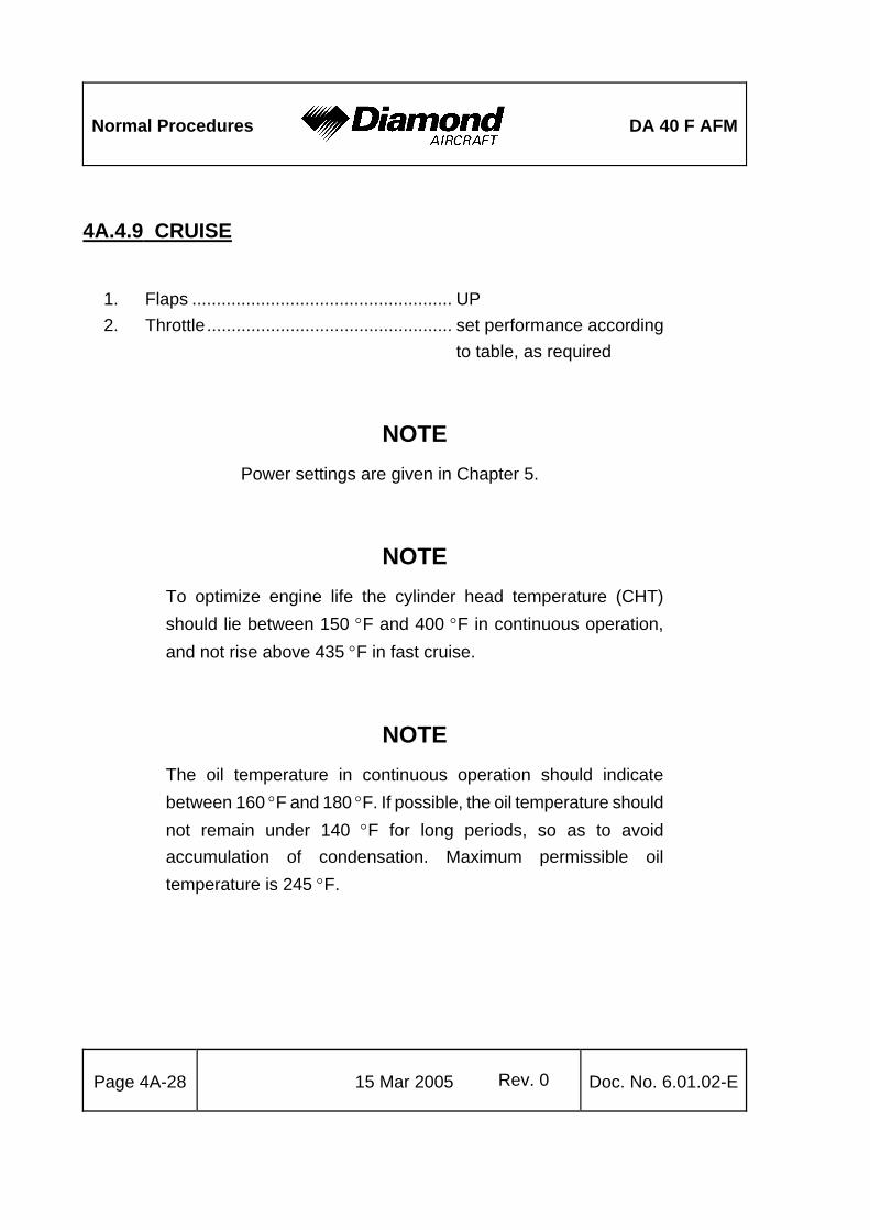
Normal Procedures
DA 40 F AFM
Page 4A-28 15 Mar 2005 Rev. 0 Doc. No. 6.01.02-E
4A.4.9 CRUISE
1. Flaps ..................................................... UP 2. Throttle.................................................. set performance according
to table, as required
NOTE Power settings are given in Chapter 5.
NOTE To optimize engine life the cylinder head temperature (CHT) should lie between 150 °F and 400 °F in continuous operation, and not rise above 435 °F in fast cruise.
NOTE The oil temperature in continuous operation should indicate between 160 °F and 180 °F. If possible, the oil temperature should not remain under 140 °F for long periods, so as to avoid accumulation of condensation. Maximum permissible oil temperature is 245 °F.

DA 40 F AFM
Normal Procedures
Doc. No. 6.01.02-E Rev. 0 15 Mar 2005
Page 4A-29
3. Mixture...................................................set in accordance with 4A.4.10 MIXTURE ADJUSTMENT
4. Trim .......................................................as required 5. Fuel tank selector ..................................as required
(max. difference 10 US gal)
NOTE While switching from one tank to the other, the electrical fuel pump should be switched ON.
CAUTION When the fuel pressure warning light illuminates, or the fuel pressure indication is below the green sector, the electrical fuel pump must be switched ON.
4A.4.10 MIXTURE ADJUSTMENT
CAUTION 1. The maximum permissible cylinder head temperature (500 °F)
must never be exceeded.
2. The mixture control lever should always be moved slowly.
3. Before selecting a higher power setting the mixture control lever should, on each occasion, be moved slowly to fully RICH.
4. Care should always be taken that the cylinders do not cool down too quickly. The cooling rate should not exceed 50 °F per minute.
NOTE For maximum service life cylinder head temperature should be kept below 435 °F (high performance cruise) and below 400 °F (for economy cruise).

Normal Procedures
DA 40 F AFM
Page 4A-30 15 Mar 2005 Rev. 0 Doc. No. 6.01.02-E
Best economy mixture
The best economy mixture setting may only be used up to a power setting of 75 %. In order to obtain the lowest specific fuel consumption at a particular power setting, proceed as follows: Slowly pull the mixture control lever back towards LEAN until the engine starts to run roughly. Then push the mixture control lever forward just far enough to restore smooth running. At the same time the exhaust gas temperature (EGT) should reach a maximum.
The exact value of EGT can be obtained by pressing the far left button on the engine instrument unit VM 1000. In the Alean@ mode one bar represents 10 °F.
Best power mixture
The mixture can be set for maximum performance at all power settings. The mixture should first be set as for >best economy=. The mixture should then be enriched until the exhaust gas temperature is approximately 50 °F lower. This mixture setting produces the maximum performance for a given manifold pressure and is mainly used for high power settings (approximately 75 %).
Alternatively, the best power setting can be established by adjusting the mixture for maximum RPM.
NOTE For climb it is recommended that the mixture be set to FULL RICH below 5000 ft pressure altitude. Lean mixture to best power above 5000 ft pressure altitude.

DA 40 F AFM
Normal Procedures
Doc. No. 6.01.02-E Rev. 0 15 Mar 2005
Page 4A-31
4A.4.11 DESCENT
1. Mixture control lever ..............................enrich as required for the altitude,
operate slowly 2. Carburetor heat......................................ON, as required 3. Throttle ..................................................as required
CAUTION When reducing power, the change in cylinder head temperature should not exceed 50 °F per minute. This is normally guaranteed by the 'self adapting inlet'. An excessive cooling rate may occur however, if the engine is very hot and the throttle is reduced abruptly in a fast descent. Shock-cooling shortens engine life.
CAUTION When the fuel pressure warning light illuminates, or the fuel pressure indication is below the green sector, the electrical fuel pump must be switched ON.
CAUTION Prior to a prolonged descent with low power settings and suspected icing conditions, FULL carburetor heat should be applied before reducing engine power. Throttle should be retarded and mixture control leaned as required. Power response should be verified approximately every 30 seconds by partially opening and then closing the throttle. When leveling off, enrich the mixture, set power as required and select carburetor heat OFF unless carburetor icing conditions are suspected.

Normal Procedures
DA 40 F AFM
Page 4A-32 15 Mar 2005 Rev. 0 Doc. No. 6.01.02-E
4A.4.12 LANDING APPROACH 1. Electrical fuel pump............................... ON 2. Fuel selector.......................................... fullest tank 3. Safety harnesses .................................. fastened 4. Airspeed................................................ reduce to operate flaps (108 KIAS) 5. Flaps ..................................................... T/O 6. Trim....................................................... as required 7. Landing light.......................................... as required 8. Carburetor heat ..................................... ON
before landing:
9. Mixture control lever.............................. RICH 10. Throttle.................................................. as required 11. Airspeed................................................ reduce to operate flaps (91 KIAS) 12. Flaps ..................................................... LDG 13. Approach speed .................................... 70 KIAS (1150 kg, 2535 lb) 63 KIAS (1000 kg, 2205 lb) 58 KIAS (850 kg, 1874 lb)
on final approach:
14. Carburetor heat ..................................... OFF
CAUTION In conditions such as (e.g.) strong wind, danger of wind shear or turbulence a higher approach speed should be selected.

DA 40 F AFM
Normal Procedures
Doc. No. 6.01.02-E Rev. 0 15 Mar 2005
Page 4A-33
4A.4.13 GO-AROUND 1. Throttle ..................................................FULL 2. Airspeed ................................................66 KIAS (1150 kg, 2535 lb) 60 KIAS (1000 kg, 2205 lb) 54 KIAS (850 kg, 1874 lb) 3. Mixture...................................................check fully RICH 4. Carburetor heat......................................check OFF 5. Flaps......................................................T/O
above a safe height:
6. Airspeed ................................................73 KIAS (1150 kg, 2535 lb) 68 KIAS (1000 kg, 2205 lb) 60 KIAS (850 kg, 1874 lb) 7. Flaps......................................................UP 8. Electrical fuel pump ...............................OFF
4A.4.14 AFTER LANDING 1. Throttle ..................................................1000 RPM 2. Brakes ...................................................as required 3. Electrical fuel pump ...............................OFF 4. Transponder ..........................................OFF / SBY 5. Pitot heating...........................................OFF 6. Avionics .................................................as required 7. Lights .....................................................as required 8. Flaps......................................................UP 9. Carburetor heat......................................OFF

Normal Procedures
DA 40 F AFM
Page 4A-34 15 Mar 2005 Rev. 0 Doc. No. 6.01.02-E
4A.4.15 ENGINE SHUT-DOWN
1. Parking brake........................................ set 2. Engine instruments ............................... check 3. ELT ....................................................... check 121.5 MHz 4. Avionics master switch.......................... OFF 5. All electrical equipment ......................... OFF 6. Throttle.................................................. 1000 RPM 7. Ignition check ........................................ OFF until RPM drops noticeably, .............................................................. then immediately BOTH again 8. Mixture control lever.............................. LEAN - shut engine off 9. Ignition switch........................................ OFF 10. Master switch / Battery+Alternator ........ OFF 11. Strobe lights (ACLs) .............................. OFF

DA 40 F AFM
Normal Procedures
Doc. No. 6.01.02-E Rev. 0 15 Mar 2005
Page 4A-35
4A.4.16 POST-FLIGHT INSPECTION
1. Parking brake.........................................release, use chocks 2. Airplane .................................................moor, if unsupervised for ...............................................................extended period
NOTE If the airplane is not operated for more than 5 days, the long-term parking procedure should be applied. If the airplane is not operated for more than 30 days, the storage procedure should be applied. Both procedures are described in the Airplane Maintenance Manual (Doc. No. 6.02.01) in Chapter 10.

Normal Procedures
DA 40 F AFM
Page 4A-36 15 Mar 2005 Rev. 0 Doc. No. 6.01.02-E
4A.4.17 FLIGHT IN RAIN
NOTE Performance deteriorates in rain; this applies particularly to the take-off distance and to the maximum horizontal speed. The effect of rain on flight characteristics is minimal. Flight through very heavy rain should be avoided because of the associated visibility problems.
CAUTION Carburetor icing:
Under certain moist atmospheric conditions it is possible for ice to form in the induction system, even in summer weather.
This is due to the high air velocity through the carburetor venturi, its liquid water content and the absorption of heat from this air by vaporization of fuel.
To avoid this, a carburetor preheat system is provided in order to replace the heat lost by vaporization. The carburetor heat should be set fully ON when carburetor icing is encountered (reduction of engine power, rough running engine etc.). Be aware of power reduction caused by switching ON the carburetor heat.
Adjust the mixture for maximum smoothness.
NOTE If carburetor icing occurs, the carburetor heat must be switched ON. Be aware of the power reduction caused by switching ON the carburetor heat.

DA 40 F AFM
Normal Procedures
Doc. No. 6.01.02-E Rev. 0 15 Mar 2005
Page 4A-37
4A.4.18 REFUELING
CAUTION Before refueling, the airplane must be connected to electrical ground. Grounding points: unpainted areas on steps, left and right.
4A.4.19 FLIGHT AT HIGH ALTITUDE
At high altitudes the provision of oxygen for the occupants is necessary. Legal requirements for the provision of oxygen must be adhered to.
Also see Section 2.11 OPERATING ALTITUDE.

Normal Procedures
DA 40 F AFM
Page 4A-38 15 Mar 2005 Rev. 0 Doc. No. 6.01.02-E
Intentionally left blank

DA 40 F AFM
Abnormal Procedures
Doc. No. 6.01.02-E Rev. 0 15 Mar 2005 Page 4B-1
CHAPTER 4B
ABNORMAL OPERATING PROCEDURES
Page 4B.1 PRECAUTIONARY LANDING ..................................................................... 4B-2 4B.2 INSTRUMENT INDICATIONS OUTSIDE OF GREEN RANGE ................... 4B-4 4B.3 FAILURES IN THE ELECTRICAL SYSTEM................................................ 4B-5 4B.4 TAKE-OFF FROM A SHORT GRASS STRIP.............................................. 4B-6 4B.5 FAILURES IN FLAP OPERATING SYSTEM ............................................... 4B-7

Abnormal Procedures
DA 40 F AFM
Page 4B-2 15 Mar 2005 Rev. 0 Doc. No. 6.01.02-E
4B.1 PRECAUTIONARY LANDING
NOTE A precautionary landing is only necessary when there is a reasonable suspicion that, due to fuel shortage, weather conditions, or at nightfall, the possibility of endangering the airplane and its occupants by continuing the flight cannot be excluded. The pilot is must decide whether or not a controlled landing in a field represents a lower risk than the attempt to reach the target airfield under all circumstances.
NOTE If no level landing area is available, a landing on an upward slope should be attempted.
1. Select appropriate landing area.
2. Consider wind.
3. Approach: If possible, the landing area should be overflown at a suitable height in order to recognize obstacles. The degree of offset at each part of the circuit will allow the wind speed and direction to be assessed.
4. Airspeed................................................ 73 KIAS (1150 kg, 2535 lb)
68 KIAS (1000 kg, 2205 lb)
60 KIAS (850 kg, 1874 lb)
5. ATC....................................................... advise

DA 40 F AFM
Abnormal Procedures
Doc. No. 6.01.02-E Rev. 0 15 Mar 2005 Page 4B-3
on final approach:
6. Flaps......................................................LDG
7. Safety harnesses ...................................tighten
8. Touchdown ............................................with the lowest possible airspeed
CAUTION If sufficient time remains, the risk in the event of a collision with obstacles can be reduced as follows:
- Fuel tank selector ...................................................... OFF
- Ignition switch............................................................ OFF
- Master switch / Battery+Alternator switch ................. OFF

Abnormal Procedures
DA 40 F AFM
Page 4B-4 15 Mar 2005 Rev. 0 Doc. No. 6.01.02-E
4B.2 INSTRUMENT INDICATIONS OUTSIDE OF GREEN RANGE
(a) High oil pressure when starting in low ambient temperatures
- Reduce RPM and re-check oil pressure at a higher oil temperature.
- If, on reducing the RPM, the indicated oil pressure does not change, it is probable that the fault lies in the oil pressure indication. Terminate flight preparation.
(b) Oil temperature
A constant reading of the oil temperature of 26 °F or 317 °F suggests a faulty oil temperature sensor. The airplane should be serviced.
(c) Cylinder head temperature and exhaust gas temperature
A very low reading of CHT or EGT for a single cylinder may be the result of a loose sensor. In this case the reading will indicate the temperature of the engine compartment. The airplane should be serviced.

DA 40 F AFM
Abnormal Procedures
Doc. No. 6.01.02-E Rev. 0 15 Mar 2005 Page 4B-5
4B.3 FAILURES IN THE ELECTRICAL SYSTEM
(a) Low voltage caution (VOLT or LOW VOLTS)
This caution is indicated when the normal on-board voltage (28 V) drops below 24.1 V. Possible reasons are:
- A fault in the power supply.
- RPM too low.
- Alternator switched OFF inadvertently
(i) 'Low Voltage' caution on the ground:
1. Engine speed.........................................1200 RPM
2. Electrical equipment ..............................OFF
3. Ammeter ................................................check
If the caution light does not extinguish, and the ammeter flashes and reads zero:
- Terminate flight preparation.
(ii) 'Low Voltage' caution during flight:
1. Electrical equipment ..............................OFF if not needed
2. Ammeter ................................................check
If the caution light does not extinguish, and the ammeter flashes and reads zero:
- Follow procedure in 3.7.2 (b) Alternator failure.
(iii) 'Low Voltage' caution during landing:
- Follow (i) after landing.

Abnormal Procedures
DA 40 F AFM
Page 4B-6 15 Mar 2005 Rev. 0 Doc. No. 6.01.02-E
4B.4 TAKE-OFF FROM A SHORT GRASS STRIP
1. Brakes................................................... apply
2. Flaps ..................................................... T/O
3. Throttle.................................................. FULL
4. Elevator (control stick)........................... fully aft
5. Brakes................................................... release
6. Hold direction ........................................ using rudder
NOTE In strong crosswinds steering can be augmented by use of the toe brakes. It should be noted, however, that this method increases the take-off roll.
7. Elevator (control stick)........................... release slowly, when nose wheel
has lifted.
Allow the airplane to lift off as soon as possible and increase speed at low level.
8. Airspeed................................................ 66 KIAS (1150 kg, 2535 lb)
60 KIAS (1000 kg, 2205 lb)
54 KIAS (850 kg, 1874 lb)
9. Flaps ..................................................... UP, above safe altitude
10. Electrical fuel pump............................... OFF, above safe altitude
11. Landing light.......................................... as required

DA 40 F AFM
Abnormal Procedures
Doc. No. 6.01.02-E Rev. 0 15 Mar 2005 Page 4B-7
4B.5 FAILURES IN FLAP OPERATING SYSTEM
Failure in position indication or function
- Check flap position visually.
- Keep airspeed in white sector.
- Re-check all positions of the flap switch.
Modified approach procedure depending on the available flap setting
(a) Only UP available:
Airspeed .............................................................73 KIAS (1150 kg, 2535 lb)
68 KIAS (1000 kg, 2205 lb)
60 KIAS (850 kg, 1874 lb)
Land at a flat approach angle, use the throttle to control airplane speed and rate of descent.
(b) Only T/O available:
Airspeed .............................................................73 KIAS (1150 kg, 2535 lb)
68 KIAS (1000 kg, 2205 lb)
60 KIAS (850 kg, 1874 lb)
Land at a flat approach angle, use throttle to control airplane speed and rate of descent.
(c) Only LDG available:
Perform normal landing.

Abnormal Procedures
DA 40 F AFM
Page 4B-8 15 Mar 2005 Rev. 0 Doc. No. 6.01.02-E
Intentionally left blank

DA 40 F AFM
Performance
Doc. No. 6.01.02-E Rev. 0 15 Mar 2005 Page 5-1
CHAPTER 5
PERFORMANCE
Page 5.1 INTRODUCTION...............................................................................................5-2 5.2 USE OF THE PERFORMANCE TABLES AND DIAGRAMS.............................5-2 5.3 PERFORMANCE TABLES AND DIAGRAMS ...................................................5-3
5.3.1 AIRSPEED CALIBRATION.........................................................................5-3 5.3.2 PRESSURE ALTITUDE - DENSITY ALTITUDE.........................................5-4 5.3.3 STALLING SPEEDS...................................................................................5-5 5.3.4 WIND COMPONENTS................................................................................5-6 5.3.5 TAKE-OFF DISTANCE ...............................................................................5-7 5.3.6 CLIMB PERFORMANCE - TAKE-OFF CLIMB .........................................5-10 5.3.7 CLIMB PERFORMANCE - CRUISE CLIMB .............................................5-12 5.3.8 ENGINE POWER SETTING, TRUE AIRSPEED, FUEL CONSUMPTION5-14 5.3.9 LANDING DISTANCE - FLAPS LDG........................................................5-18 5.3.10 GRADIENT OF CLIMB ON GO-AROUND..............................................5-22 5.3.11 APPROVED NOISE DATA .....................................................................5-22

Performance
DA 40 F AFM
Page 5-2 15 Mar 2005 Rev. 0 Doc. No. 6.01.02-E
5.1 INTRODUCTION
The performance tables and diagrams on the following pages are presented so that, on the one hand, you can see what performance you can expect from your airplane, while on the other, they allow for comprehensive and accurate flight planning. The values in the tables and the diagrams were obtained by means of flight trials using an airplane and power-plant in good condition, and corrected to the conditions of the International Standard Atmosphere (ISA = 15 EC/59 °F and 1013.25 hPa/29.92 inHg at sea level).
The performance diagrams do not take into account variations in pilot experience or a poorly maintained airplane. The performances given can be attained if the procedures quoted in this manual are applied, and the airplane has been well maintained.
Where appropriate, any flight performance degradation resulting from the absence of wheel fairings is given as a percentage.
5.2 USE OF THE PERFORMANCE TABLES AND DIAGRAMS
In order to illustrate the influence of a number of different variables, performance data is reproduced in the form of tables or diagrams. These contain sufficiently detailed information so that conservative values can be selected and used for the determination of adequate performance data for the planned flight.

DA 40 F AFM
Performance
Doc. No. 6.01.02-E Rev. 0 15 Mar 2005 Page 5-3
5.3 PERFORMANCE TABLES AND DIAGRAMS
5.3.1 AIRSPEED CALIBRATION

Performance
DA 40 F AFM
Page 5-4 15 Mar 2005 Rev. 0 Doc. No. 6.01.02-E
5.3.2 PRESSURE ALTITUDE - DENSITY ALTITUDE
Conversion from pressure altitude to density altitude.
standard temperature
dens
ity a
lt. [f
t]
dens
ity a
lt. [m
]
pres
sure
alti
tude
[m]
pres
sure
alti
tude
[ft]
temperature
-2000
14000
12000
10000
12000
14000
10000
8000
6000
4000
2000
0
8000
8000
6000
4000
2000
0 0
500
1000
1500
2000
2500
3000
3500
4000
0
500
1000
1500
2000
2500
3000
3500
4000
-20 -10 0 10 20 30
-500
32 50 68 8614-4
[°C][°F]
Example: 1. Set 1013.25 hPa on altimeter and read pressure altitude (900 ft). 2. Establish ambient temperature (+21 EC). 3. Read off density altitude (1800 ft). Result: From a performance calculation standpoint the airplane is at 1800 ft.

DA 40 F AFM
Performance
Doc. No. 6.01.02-E Rev. 0 15 Mar 2005 Page 5-5
5.3.3 STALLING SPEEDS
Mass: 980 kg (2161 lb)
Airspeeds in KIAS
Bank Angle 980 kg 2161 lb 0° 30° 45° 60°
UP 47 52 58 73
T/O 44 51 58 72 Flaps
LDG 42 49 57 71
Mass: 1150 kg (2535 lb)
Airspeeds in KIAS
Bank Angle 1150 kg 2535 lb 0° 30° 45° 60°
UP 52 57 66 79
T/O 51 55 64 78 Flaps
LDG 49 55 62 76

Performance
DA 40 F AFM
Page 5-6 15 Mar 2005 Rev. 0 Doc. No. 6.01.02-E
5.3.4 WIND COMPONENTS
Example: Flight direction : 360° Wind : 32°/30 kts Result: Crosswind component : 16 kts Max. demonstrated crosswind component : 20 kts

DA 40 F AFM
Performance
Doc. No. 6.01.02-E Rev. 0 15 Mar 2005 Page 5-7
5.3.5 TAKE-OFF DISTANCE Conditions: - Throttle........................................................FULL - Mixture ........................................................RICH (below 5000 ft) - Carburetor Heat ..........................................OFF - Flaps ...........................................................T/O - Lift-off speed ...............................................approx. 59 KIAS - Climb-out speed..........................................66 KIAS (1150 kg, 2535 lb) 60 KIAS (1000 kg, 2205 lb) 54 KIAS (850 kg, 1874 lb) - Runway.......................................................level, asphalt surface
WARNING On grass strips, depending on the characteristics of the surface (length of the grass, softness of the ground), allowance must be made for a take-off roll which is at least 20 % longer. The take-off distance values given do not include any kind of safety margin. A poorly maintained airplane, deviation from the prescribed procedures and unfavorable external factors (rain, cross-wind, wind shear, uneven terrain and in particular tufts of grass) can all lead to a considerable increase in the take-off distance.
CAUTION A ground slope of 2 % (2 m per 100 m, or 2 ft per 100 ft) results in an increase in the take-off distance of approximately 10 %. The effect on the take-off roll can be greater.
WARNING For a safe take-off, the available runway length must be at least equal to the take-off distance over a 50 ft (15 m) obstacle.

Performance
DA 40 F AFM
Page 5-8 15 Mar 2005 Rev. 0 Doc. No. 6.01.02-E

DA 40 F AFM
Performance
Doc. No. 6.01.02-E Rev. 0 15 Mar 2005 Page 5-9

Performance
DA 40 F AFM
Page 5-10 15 Mar 2005 Rev. 0 Doc. No. 6.01.02-E
5.3.6 CLIMB PERFORMANCE - TAKE-OFF CLIMB Conditions: - Throttle ....................................................... FULL - Mixture........................................................ RICH (below 5000 ft) - Carburetor Heat.......................................... OFF - Flaps .......................................................... T/O
- Airspeed ..................................................... 66 KIAS (1150 kg, 2535 lb) 60 KIAS (1000 kg, 2205 lb) 54 KIAS (850 kg, 1874 lb)

DA 40 F AFM
Performance
Doc. No. 6.01.02-E Rev. 0 15 Mar 2005 Page 5-11

Performance
DA 40 F AFM
Page 5-12 15 Mar 2005 Rev. 0 Doc. No. 6.01.02-E
5.3.7 CLIMB PERFORMANCE - CRUISE CLIMB Conditions: - Throttle ....................................................... FULL - Mixture........................................................ RICH (below 5000 ft) - Carburetor Heat.......................................... OFF - Flaps .......................................................... UP - Airspeed ..................................................... 73 KIAS (1150 kg, 2535 lb) 68 KIAS (1000 kg, 2205 lb) 60 KIAS (850 kg, 1874 lb)
NOTE The graph on the following page shows the rate of climb. The gradient of climb cannot easily be determined with a graph, but it can be calculated using the following formulae:
Gradient ROC fpmTAS KTAS[%] [ ]
[ ] . = ⋅ 0 95
Gradient ROC m sTAS KTAS[%] [ / ]
[ ] = ⋅190

DA 40 F AFM
Performance
Doc. No. 6.01.02-E Rev. 0 15 Mar 2005 Page 5-13

Performance
DA 40 F AFM
Page 5-14 15 Mar 2005 Rev. 0 Doc. No. 6.01.02-E
5.3.8 ENGINE POWER SETTING, TRUE AIRSPEED, FUEL CONSUMPTION

DA 40 F AFM
Performance
Doc. No. 6.01.02-E Rev. 0 15 Mar 2005 Page 5-15
CAUTION
In case of operation without wheel fairings the cruising speed reduces by approximately 5 %.
NOTE An auxiliary fuel below 3 US gal cannot be indicated by the system. If a fuel indicater shows 17 US gal and the auxiliary fuel indicator 0 US gal for the same fuel tank, for in-flight consumption / flight planning a fuel quantity available of 17 US gal must be assumed.

Performance
DA 40 F AFM
Page 5-16 15 Mar 2005 Rev. 0 Doc. No. 6.01.02-E

DA 40 F AFM
Performance
Doc. No. 6.01.02-E Rev. 0 15 Mar 2005 Page 5-17

Performance
DA 40 F AFM
Page 5-18 15 Mar 2005 Rev. 0 Doc. No. 6.01.02-E
5.3.9 LANDING DISTANCE - FLAPS LDG
Conditions: - Throttle ....................................................... IDLE - Mixture........................................................ RICH (below 5000 ft) - Carburetor Heat.......................................... OFF - Flaps .......................................................... LDG - Approach speed ......................................... 71 KIAS (1150 kg, 2535 lb) 63 KIAS (1000 kg, 2205 lb) 58 KIAS (850 kg, 1874 lb) - Runway ...................................................... level, asphalt surface
values for ISA and MSL, at 1150 kg (2535 lb)
Landing distance over a 50 ft (15 m) obstacle approx. 817 m (2680 ft)
Ground roll approx. 466 m (1529 ft)
CAUTION On grass strips, depending on the characteristics of the surface (particularly moisture), allowance must be made for a ground roll which is up to 50 % longer.
A poorly maintained airplane, deviation from the prescribed procedures and unfavorable external factors (high temperature, rain, unfavorable wind effects, etc.) can considerably increase the landing distance.

DA 40 F AFM
Performance
Doc. No. 6.01.02-E Rev. 0 15 Mar 2005 Page 5-19
CAUTION A descending ground slope of 2 % (2 m per 100 m, or 2 ft per 100 ft) results in an increase in the landing distance of approximately 10 %. The effect on the ground roll can be greater.
WARNING For a safe landing the available runway length must be at least equal to the landing distance over a 50 ft (15 m) obstacle.

Performance
DA 40 F AFM
Page 5-20 15 Mar 2005 Rev. 0 Doc. No. 6.01.02-E
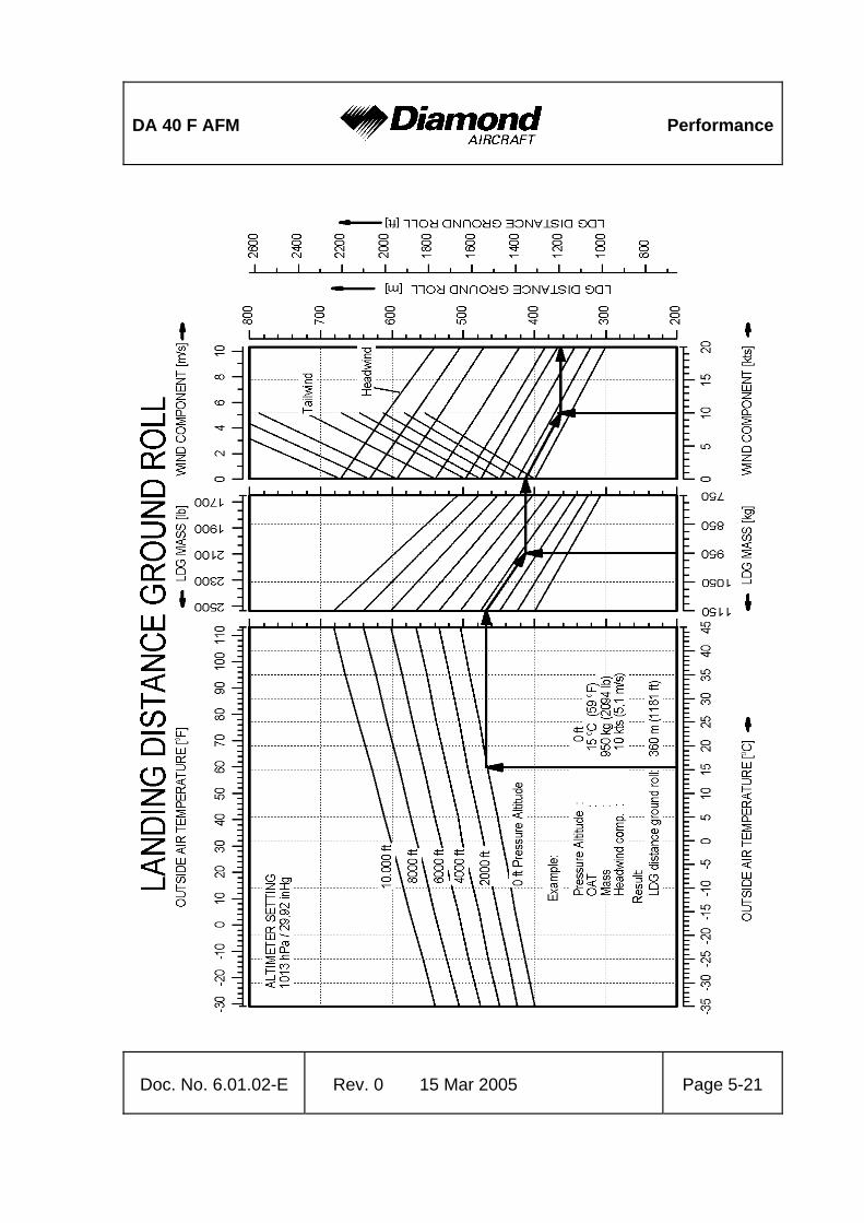
DA 40 F AFM
Performance
Doc. No. 6.01.02-E Rev. 0 15 Mar 2005 Page 5-21

Performance
DA 40 F AFM
Page 5-22 15 Mar 2005 Rev. 0 Doc. No. 6.01.02-E
5.3.10 GRADIENT OF CLIMB ON GO-AROUND
The DA 40 F reaches a constant gradient of climb of 8.2 % in the following condition: - Mass ..................................................... max. flight mass (1150 kg, 2535 lb) - Throttle.................................................. FULL - Mixture .................................................. RICH - Carburetor Heat .................................... OFF - Flaps ..................................................... LDG - Airspeed................................................ 70 KIAS - ISA, MSL
5.3.11 APPROVED NOISE DATA
ICAO Annex 16, Volume 1, Part II, Chapter X ... ………………..74.8 dB(A)

DA 40 F AFM
Mass and Balance
Doc. No. 6.01.02-E Rev. 0 15 Mar 2005 Page 6-1
CHAPTER 6
MASS AND BALANCE Page
6.1 INTRODUCTION................................................................................................6-2 6.2 DATUM PLANE..................................................................................................6-3 6.3 MASS AND BALANCE REPORT .......................................................................6-3 6.4 FLIGHT MASS AND CENTER OF GRAVITY.....................................................6-5
6.4.1 MOMENT ARMS..........................................................................................6-8 6.4.2 LOADING DIAGRAM...................................................................................6-9 6.4.3 CALCULATION OF LOADING CONDITION..............................................6-10 6.4.4 PERMISSIBLE CENTER OF GRAVITY RANGE.......................................6-11 6.4.5 PERMISSIBLE MOMENT RANGE ............................................................6-13
6.5 EQUIPMENT LIST AND EQUIPMENT INVENTORY.......................................6-14

Mass and Balance
DA 40 F AFM
Page 6-2 15 Mar 2005 Rev. 0 Doc. No. 6.01.02-E
6.1 INTRODUCTION
In order to achieve the performance and flight characteristics described in this Airplane Flight Manual and for safe flight operation, the airplane must be operated within the permissible mass and balance envelope.
The pilot is responsible for adhering to the permissible values for loading and center of gravity (CG). In this, he should note the movement of the CG due to fuel consumption. The permissible CG range during flight is given in Section 6.4.4.
The procedure for determining the flight mass CG position at any point in time is described in this Chapter. Over and above this there is a comprehensive list of the equipment approved for this airplane (Equipment List), as also a list of that equipment installed when the airplane was weighed (Equipment Inventory).
Before the airplane is delivered the empty mass and the corresponding CG position are determined, and entered in Section 6.3 MASS AND BALANCE REPORT.
NOTE Following equipment changes the new empty mass and the corresponding CG position must be determined by calculation or by weighing.
Following repairs or repainting the new empty mass and the corresponding CG position must be determined by weighing.
Empty mass, empty mass CG position, and the empty mass moment must be certified in the Mass and Balance Report by an authorized person.
NOTE Refer to Section 1.6 UNITS OF MEASUREMENT for
conversion of SI units to US units and vice versa.

DA 40 F AFM
Mass and Balance
Doc. No. 6.01.02-E Rev. 0 15 Mar 2005 Page 6-3
6.2 DATUM PLANE
The Datum Plane (DP) is a plane which is normal to the airplane=s longitudinal axis and in front of the airplane as seen from the direction of flight. The airplane=s longitudinal axis is parallel with the upper surface of a 600:31 wedge which is placed on top of the rear fuselage in front of the vertical stabilizer. When the upper surface of the wedge is aligned horizontally, the Datum Plane is vertical. The Datum Plane is located 2.194 meters (86.38 in) forward of the most forward point of the root rib on the stub wing.
6.3 MASS AND BALANCE REPORT
The empty mass and the corresponding CG position established before delivery are the first entries in the Mass and Balance Report. Every change in permanently installed equipment, and every repair to the airplane which affects the empty mass or the empty mass CG must be recorded in the Mass and Balance Report.
For the calculation of flight mass and corresponding CG position (or moment), the current empty mass and the corresponding CG position (or moment) in accordance with the Mass and Balance Report must always be used.
Condition of the airplane for establishing the empty mass:
- Equipment as per Equipment Inventory (see Section 6.5)
- Including brake fluid, lubricant (7.6 liters = 8 qts), plus unusable fuel (4 liters = approx. 1 US gal).

Mass and Balance
DA 40 F AFM
Page 6-4 15 Mar 2005 Rev. 0 Doc. No. 6.01.02-E
MASS AND BALANCE REPORT (Continuous report on structural or equipment changes)
Mo-
men
t
Mo-
men
t Ar
m
Page
No.
:
Cur
rent
Em
pty
Mas
s
Mas
s
Mo-
men
t
Mo-
men
t Ar
m
Reg
istra
tion:
Subt
ract
ion
(-)
Mas
s
Mo-
men
t
Mo-
men
t Ar
m
Seria
l No.
:
Cha
nges
in m
ass
Addi
tion
(+)
Mas
s
Des
crip
tion
of
part
or
mod
ifica
tion
Upo
n de
liver
y
OU
T
Entry
No.
:
IN
DA
40 F
Dat
e

DA 40 F AFM
Mass and Balance
Doc. No. 6.01.02-E Rev. 0 15 Mar 2005 Page 6-5
6.4 FLIGHT MASS AND CENTER OF GRAVITY
The following information enables you to operate your DA 40 F within the permissible mass and balance limits. For the calculation of the flight mass and the corresponding CG position the following tables and diagrams are required:
6.4.1 MOMENT ARMS 6.4.2 LOADING DIAGRAM 6.4.3 CALCULATION OF LOADING CONDITION 6.4.4 PERMISSIBLE CENTER OF GRAVITY RANGE 6.4.5 PERMISSIBLE MOMENT RANGE
The diagrams should be used as follows:
1. Take the empty mass and the empty mass moment of your airplane from the Mass and Balance Report, and enter the figures in the appropriate boxes under the column marked >Your DA 40 F' in Table 6.4.3 - >CALCULATION OF LOADING CONDITION=.
2. Read the fuel quantity indicators to determine the fuel quantity.
a) Standard Tank:
NOTE If an indicator shows 17 US gal, up to 20 US gal can be in the tank. In this case, the exact quantity must be determined with the fuel quantity measuring device. If this measurement is not carried out, the fuel quantity for mass and CG calculation must be assumed to be 20 US gal.

Mass and Balance
DA 40 F AFM
Page 6-6 15 Mar 2005 Rev. 0 Doc. No. 6.01.02-E
b) Long Range Tank (if installed):
NOTE When the fuel quantity indicator reads 16 US gal, read the auxiliary fuel quantity by setting the AUX FUEL QTY switch to the appropriate position (LH or RH), and add the auxiliary fuel quantity to the 16 US gal.
NOTE An auxiliary fuel quantity below 3 US gal cannot be indicated by the system. For auxiliary fuel quantities below 3 US gal, the correct fuel quantity must be determined with the fuel quantity measuring device (see section 7.10 FUEL SYSTEM). If this measurement is not carried out, the fuel quantity for mass and CG calculation must be assumed to be 20 US gal.
3. The difference between the actual amount of oil in the engine (check with dipstick) and the maximum oil quantity is called >Oil not added=; this mass and its related moment are counted as negative. The empty mass of the airplane is established with the maximum amount of oil in the engine, thus the >missing= oil must be subtracted. If the airplane is flown with maximum oil, the >Oil not added= entry should be zero.
In our example 6.0 qts have been measured on the dip-stick. We are thus 2.0 qts short of the maximum, which equates to 1.9 liters. Multiplying this quantity by the mass density of 0.89 kilograms per liter gives a mass of >Oil not added= of 1.7 kg. (In U.S. units: 2.0 qts multiplied by the mass density of 1.86 lb/qts gives a mass of 3.7 lb.)
4. Multiply the individual masses by the moment arms quoted to obtain the moment for every item of loading and enter these moments in the appropriate boxes in Table 6.4.3 - >CALCULATION OF LOADING CONDITION=.

DA 40 F AFM
Mass and Balance
Doc. No. 6.01.02-E Rev. 0 15 Mar 2005 Page 6-7
5. Add up the masses and moments in the respective columns. The total moments may be rounded to whole numbers. The CG position is calculated by dividing the total moment by the total mass (using row 6 for the condition with empty fuel tanks, and row 8 for the pre take-off condition). The resulting CG position must be inside the limits.
As an illustration the total mass and the CG position are entered on Diagram 6.4.4 'PERMISSIBLE CENTER OF GRAVITY RANGE'. This checks graphically that the current configuration of the airplane is within the permissible range.
6. Graphical method:
Diagram 6.4.2 'LOADING DIAGRAM' is used to determine the moments. The masses and moments for the individual items of loading are added. Then Diagram 6.4.5 'PERMISSIBLE MOMENT RANGE' is used to check whether the total moment associated with the total mass is in the admissible range.
The result found with the graphical method is however inaccurate. In doubtful cases the result must be verified using the exact method given above.

Mass and Balance
DA 40 F AFM
Page 6-8 15 Mar 2005 Rev. 0 Doc. No. 6.01.02-E
6.4.1 MOMENT ARMS
The most important lever arms aft of the Datum Plane:
- Oil : 1.00 m 39.4 in
- Front seats : 2.30 m 90.6 in
- Rear seats : 3.25 m 128.0 in
- Wing tank : 2.63 m 103.5 in
- Baggage : 3.65 m 143.7 in
3.65 m (143.7 in)
3.25 m (128.0 in)
2.63 m (103.5 in)
1.00 m (39.4 in)
2.30 m (90.6 in)
2.194 m (86.4 in)
600 mm(23.62 in)
31 m
m(1
.22
in)
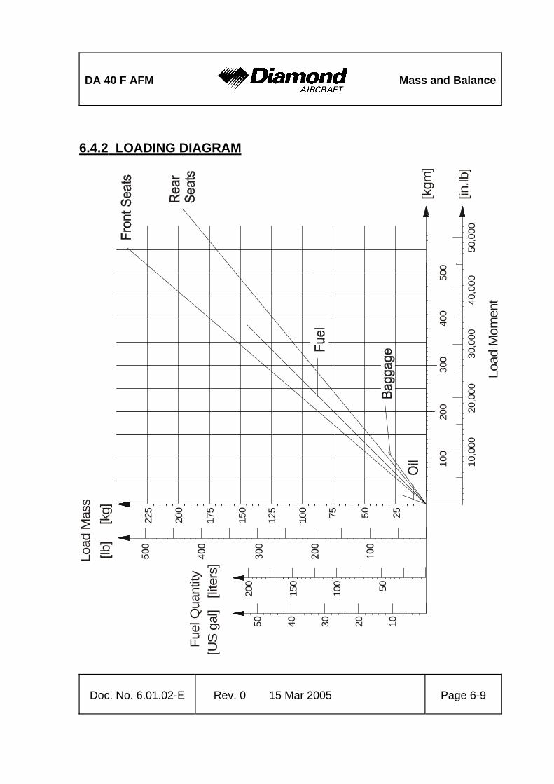
DA 40 F AFM
Mass and Balance
Doc. No. 6.01.02-E Rev. 0 15 Mar 2005 Page 6-9
6.4.2 LOADING DIAGRAM
2550100
125
150
175
200
225 75[kg]
[lb]
Load
Mas
s
10,0
0020
,000
30,0
0040
,000
50,0
00
100
200
300
400
500
[kgm
]
[in.lb
]
50100
150
10203040
Fuel
Qua
ntity
[US
gal]
[lite
rs]
Load
Mom
ent
200
50

Mass and Balance
DA 40 F AFM
Page 6-10 15 Mar 2005 Rev. 0 Doc. No. 6.01.02-E
6.4.3 CALCULATION OF LOADING CONDITION DA 40 F
(Example) Your DA 40 F
CALCULATION OF LOADING CONDITION Mass
[kg] [lb]
Moment[kgm] [in.lb]
Mass [kg] [lb]
Moment [kgm] [in.lb]
1. Empty mass (from Mass and Balance Report)
735 1620
1820 158,000
2. Oil not added Lever arm: 1.00 m (39.4 in)
-1.7 -3.7
-1.7 -146
3. Front seats Lever arm: 2.30 m (90.6 in)
150 331
345 29,989
4. Rear seats Lever arm: 3.25 m (128.0 in)
75 165.5
244 21.184
5. Baggage Lever arm: 3.65 m (143.7 in)
0 0
0 0
6. Total mass and total moment with empty fuel tanks (Total of 1.-5.)
958.3 2112.8
2407 209.027
7. On-board usable fuel (0.72 kg/liter) (6.01 lb/US gal) Lever arm: 2.63 m (103.5 in)
134.0 295.4
352 30.574
8. Total mass and total moment with full fuel tanks (Total 6. plus 7.)
1092.3 2408.2
2759 239.601
9. The total moments from rows 6 and 8 (2407 and 2759 kgm) (209.027 and 239.601 in.lb) must be divided by the related total mass (958.3 and 1092.3 kg respectively) (2112.8 and 2408.2 lb) and then located in Diagram 6.4.4 'PERMISSIBLE CENTER OF GRAVITY RANGE'. As in our example CG positions (2.512 m and 2.526 m respectively) (98.93 and 99.49 in) and masses fall into the permitted area, this loading condition is allowable.

DA 40 F AFM
Mass and Balance
Doc. No. 6.01.02-E Rev. 0 15 Mar 2005 Page 6-11
6.4.4 PERMISSIBLE CENTER OF GRAVITY RANGE
750800850900950
1000105011001150
2.40 2.45 2.50 2.55
CG
Envelope
Utility & Normal
Normal
Center of Gravity Position [m]
Flig
ht M
ass
[kg]
1800
2000
2200
2400
2600
Flig
ht M
ass
[lb]
1150 kg / 2535 lb
980 kg / 2161 lb
780 kg / 1720 lb
Center of Gravity Position [in]101100989694
2.59
102
The CG shown in the diagram is that from the example in Table 6.4.3 'CALCULATION OF LOADING CONDITION', row 8 (pre take-off condition).
The flight CG position must lie within the following limits:
Most forward flight CG:
2.40 m (94.5 in) aft of Datum Plane at 780 to 980 kg (1720 to 2161 lb)
2.46 m (96.9 in) aft of Datum Plane at 1150 kg (2535 lb)
linear variation between these values

Mass and Balance
DA 40 F AFM
Page 6-12 15 Mar 2005 Rev. 0 Doc. No. 6.01.02-E
Most rearward flight CG:
a) Standard Tank:
2.59 m (102.0 in) aft of Datum Plane
b) Long Range Tank (if installed):
2.55 m (100.4 in) aft of Datum Plane

DA 40 F AFM
Mass and Balance
Doc. No. 6.01.02-E Rev. 0 15 Mar 2005 Page 6-13
6.4.5 PERMISSIBLE MOMENT RANGE 16
0,00
018
0,00
020
0,00
022
0,00
024
0,00
026
0,00
0
FLIG
HT
MAS
S M
OM
ENT
[in.lb
]
FLIG
HT
MAS
S M
OM
ENT
[kgm
]
Center
of G
ravit
y
Positio
n
2.40 m
/ 94.5
"
2.46 m
/ 96.9
"
2.50 m
/ 98.4
"
2.55 m
/ 100
.4"
2.59 m
/ 102
.0"
1700
1800
1900
2000
2100
2200
2300
2400
2500
2550
FLIGHT MASS [lb]
FLIGHT MASS [kg]
Stan
dard
Tan
k on
ly

Mass and Balance
DA 40 F AFM
Page 6-14 15 Mar 2005 Rev. 0 Doc. No. 6.01.02-E
6.5 EQUIPMENT LIST AND EQUIPMENT INVENTORY
All equipment that is approved for installation in the DA 40 F is shown in the Equipment List below.
The items of equipment installed in your particular airplane are indicated in the appropriate column. The set of items marked as 'installed' constitutes the Equipment Inventory. Airplane Serial No.: Registration: Date:
Description Type Part No. Manufacturer S/N in-
stalledAVIONICS COOLING Avionics Cooling fan ACF 328 ACF 328 Sandia Aerospace COMMUNICATION COMM 1 antenna DMC63-1/A DM COMM 2 antenna DMC63-2 DM COMM #1 GNS 430 011-00280-00 Garmin COMM #1 GNS 430 011-00280-10 Garmin Audio Panel / Marker / ICS GMA 340 010-00152-00 Garmin ICS PM1000 II 11922 PS Engineering Headset, pilot Echelon 100 Telex Headset, co-pilot Echelon 100 Telex Headset, LH pax Echelon 100 Telex Headset, RH pax Echelon 100 Telex Speaker FRS8 /4 Ohms Visaton Handmic 100TRA 62800-001 Telex ELECTRICAL POWER Battery CB24-11M (G243) Concorde (Gill) Ammeter current sensor VM1000 3010022 Vision Microsyst. Voltage regulator VR2000-28-1 Electrosyst., Inc. External power connector DAI Alternator ALU-8521LS ALU-8521LS Electrosyst., Inc.

DA 40 F AFM
Mass and Balance
Doc. No. 6.01.02-E Rev. 0 15 Mar 2005 Page 6-15
Airplane Serial No.: Registration: Date:
Description Type Part No. Manufacturer S/N in-
stalledEQUIPMENT Safety belts, pilot 5-01-1C0701 Schroth Safety belts, co-pilot 5-01-1C5701 Schroth Safety belts, RH pax 5-01-1B0701 Schroth Safety belts, LH pax 5-01-1B5701 Schroth ELT unit E-01 ACK ELT remote switch E0105 ACK ELT antenna E0109 ACK MLG SPK LH DA4-3219-01-00 DAI MLG SPK RH DA4-3219-02-00 DAI NLG SPK DA4-3229-00-00 DAI FLIGHT CONTROLS Stall horn DAI-9031-00-00 DAI Flaps control unit (inst. panel) 430550 DAI Flaps actuator assy 430555 DAI SAFETY EQUIPMENT Fire extinguisher, portable HAL1 AIR Total First aid kit FUEL Fuel qty indicator VM1000 4010028 Vision Microsyst. Fuel qty sensor LH VM1000 30100-11 Vision Microsyst. Fuel qty sensor RH VM1000 30100-11 Vision Microsyst. Fuel qty sensor LH (auxiliary fuel) VM1000 3010050 Vision Microsyst.
Fuel qty sensor RH (auxiliary fuel) VM1000 3010050 Vision Microsyst.

Mass and Balance
DA 40 F AFM
Page 6-16 15 Mar 2005 Rev. 0 Doc. No. 6.01.02-E
Airplane Serial No.: Registration: Date:
Description Type Part No. Manufacturer S/N in-
stalledHYDRAULIC Brake master cylinder 10-54A Cleveland Brake parking valve 60-5B Cleveland Brake assembly 30-239A Cleveland INDICATING / REC. SYSTEMS Digital chronometer Model 803 Davtron Flight timer 85000-12 Hobbs Flight timer 85094-12 Hobbs Annunciator panel WW-IDC 001 White Wire CO detector Model 452-201 CO Guardian LLC LIGHTS Map/Reading light assy crew W1461.0.010 Rivoret Cabin light W1461.0.010 Rivoret Instr./Radio lights dimmer WW-LCM-002 White Wire Glareshield lamp assy DA4-3311-10-01 DAI Glareshield light inverter
APVL328-8-3-L-18QF Quantaflex
Strobe/Pos. light assy LH A600-PR-D-28 01-0790006-05 Whelen Strobe/Pos. light assy RH A600-PG-D-28 01-0790006-07 Whelen Strobe light power supply LH/RH
A490ATS-CF-14/28 01-0770062-05 Whelen
Taxi light 70346 01-0770346-05 Whelen Landing light 70346 01-0770346-03 Whelen Electroluminescent lamps Quantaflex 1600 Quantaflex NAVIGATION Pitot/Static probe, heated DAI-9034-57-00 DAI P/S probe HTR fail sensor DA4-3031-01-00 DAI Altimeter inHg /mbar, primary 5934PD-3 United In. Altimeter inHg /mbar, primary LUN 1128 1128-14B6 Mikrotechna Altimeter inHg /mbar, secondary 5934PD-3 United In.

DA 40 F AFM
Mass and Balance
Doc. No. 6.01.02-E Rev. 0 15 Mar 2005 Page 6-17
Airplane Serial No.: Registration: Date:
Description Type Part No. Manufacturer S/N in-
stalledAltimeter inHg /mbar, secondary LUN 1128 1128-14B6 Mikrotechna Vertical speed indicator 7000 United In. Vertical speed indicator LUN 1144 1144-A4B4 Mikrotechna Airspeed indicator 8025 United In. Airspeed indicator LUN 1116 1116-B4B3 Mikrotechna Magnetic compass C2400L4P Airpath Dir. gyro, free AIM2051BLD 505-0031-931 BF-Goodrich Attitude indicator AIM1100-28L(0F) 504-0111-936 BF-Goodrich Attitude indicator AIM1100-28LK(0F) 504-0111-938 BF-Goodrich Attitude indicator AIM1100-28LK(2F) 504-0111-941 BF-Goodrich Turn coordinator w/o AP pickup 1394T100-(3Z) Mid Continent Instr. Transponder GTX 327 011-00490-00 Garmin XPDR antenna KA60 071-01174-0000 Bendix/King XPDR antenna KA60 071-01591-0001 Bendix/King Altitude Data System SAE5-35 305154-00 Sandia Aerospace NAV antenna coupler CI505 Comant VOR/LOC/GS antenna CI157P Comant NAV/COM/GPS#1 GNS 430 011-00280-00 Garmin NAV/COM/GPS#1 GNS 430 011-00280-10 Garmin CDI, VOR/LOC/GS#1 GI 106A 013-00049-01 Garmin GPS antenna #1 GA 56 011-00134-00 Garmin ENGINE O-360-A4M Textron Lycoming ENGINE FUEL CONTROL Fuel flow transmitter VM1000 3010073 Vision Microsyst. Fuel pressure transmitter VM1000 3010046 Vision Microsyst. ENGINE IGNITION SYSTEM SlickSTART booster SS1001 Unison Magneto RH/LH 4370/4347 Slick Magneto RH/LH 4770/4771 Slick ENGINE INDICATING RPM sensor VM1000 3010005 Vision Microsyst.

Mass and Balance
DA 40 F AFM
Page 6-18 15 Mar 2005 Rev. 0 Doc. No. 6.01.02-E
Airplane Serial No.: Registration: Date:
Description Type Part No. Manufacturer S/N in-
stalledManifold pressure sensor VM1000 3010047 Vision Microsyst. Cyl. head temp. probes (4 each) VM1000 1020061 Vision Microsyst. EGT probes VM1000 1020060 Vision Microsyst. Data processing unit1 DPU 4010081 Vision Microsyst. Intergr. engine data display VM1000 4010050 Vision Microsyst. I/O board assy. 3020018 Vision Microsyst. ENGINE OIL Oil temperature sensor VM1000 3010021 Vision Microsyst. Oil pressure transducer VM1000 3010041 Vision Microsyst. ENGINE STARTING Starter 149-24LS SKYTEC PROPELLER 76EM8S10-0-63 Sensenich AIRPLANE FLIGHT MANUAL Doc. No
6.01.02-E DAI
1. DPU with P/N4010081 or DPU with P/N3034241 and Software revision V2.001, for the
Standard Tank.
Place: ____________
Date: ____________
Signature: ____________

DA 40 F AFM
Airplane Description
Doc. No. 6.01.02-E Rev. 0 15 Mar 2005 Page 7-1
CHAPTER 7
DESCRIPTION OF THE AIRPLANE AND ITS SYSTEMS
Page 7.1 INTRODUCTION...............................................................................................7-2 7.2 AIRFRAME........................................................................................................7-2 7.3 FLIGHT CONTROLS.........................................................................................7-3 7.4 INSTRUMENT PANEL ......................................................................................7-8 7.5 LANDING GEAR .............................................................................................7-11 7.6 SEATS AND SAFETY HARNESSES ..............................................................7-13 7.7 BAGGAGE COMPARTMENT .........................................................................7-13 7.8 CANOPY, REAR DOOR, AND CABIN INTERIOR ..........................................7-14 7.9 POWER PLANT ..............................................................................................7-16
7.9.1 ENGINE, GENERAL.................................................................................7-16 7.9.2 OPERATING CONTROLS........................................................................7-17 7.9.3 PROPELLER ............................................................................................7-19 7.9.4 ENGINE INSTRUMENTS .........................................................................7-20
7.10 FUEL SYSTEM .............................................................................................7-26 7.11 ELECTRICAL SYSTEM.................................................................................7-35
7.11.1 GENERAL...............................................................................................7-36 7.11.2 WHITE WIRE ANNUNCIATOR PANEL ..................................................7-40
7.12 PITOT-STATIC SYSTEM ..............................................................................7-44 7.13 STALL WARNING .........................................................................................7-44 7.14 AVIONICS .....................................................................................................7-44

Airplane Description
DA 40 F AFM
Page 7-2 15 Mar 2005 Rev. 0 Doc. No. 6.01.02-E
7.1 INTRODUCTION
Chapter 7 contains a description of the airplane and its systems, together with operating instructions.
For details about optional equipment see Chapter 9.
7.2 AIRFRAME
Fuselage
The GFRP fuselage is of semi monocoque molded construction. The fire protection on the firewall is of a special fire-resistant matting, which is covered on the engine side by stainless steel cladding. The two main bulkheads are GFRP/CFRP items.
Wings
The wings have a front and rear spar; each wing has a top shell and a bottom shell - a >fail-safe> concept. The wings, as well as the aileron and flaps, are made of GFRP/CFRP, and are principally of sandwich construction. An aluminum fuel tank is installed in each of the wings.
Empennage
The airplane has a >T= tail of GFRP semi monocoque construction. Both the stabilizers have twin spars and a skin with no sandwich. Rudder and elevator are of sandwich construction.

DA 40 F AFM
Airplane Description
Doc. No. 6.01.02-E Rev. 0 15 Mar 2005 Page 7-3
7.3 FLIGHT CONTROLS
The ailerons, elevator and wing flaps are operated through control rods, while the rudder is controlled by cable. The flaps are electrically operated. Elevator forces can be balanced by a trim tab on the elevator, which is operated by a Bowden cable.
Ailerons
Construction: GFRP/CFRP composite sandwich.
Hinges: There are 4 hinges, which are hinge pins mounted in an aluminum bracket. They are secured in position by a roll pin. The absence of this roll pin can lead to the loss of the hinge pin and a consequent loss of flight safety.
Operation: A rod-end bearing is screwed into a steel push rod and locked by means of a nut which has locking varnish applied to it. Damage to this varnish can indicate a twisting and thus a change to the adjustment. The connection between the rod-end bearing and the control horn is a bolt, the nut of which is likewise sealed with locking varnish.
The aluminum control horn is attached to the aileron with 3 screws.

Airplane Description
DA 40 F AFM
Page 7-4 15 Mar 2005 Rev. 0 Doc. No. 6.01.02-E
Flaps
Construction: GFRP/CFRP composite sandwich.
Hinges: There are 6 hinges, which are hinge pins mounted in an aluminum bracket. They are secured in position by a roll pin. The absence of this roll pin can lead to the loss of the hinge pin and a consequent loss of flight safety. Another aluminum fitting is located at the fuselage and is attached to a torsion tube. The torsion tube is located in the fuselage, creating a connection between the left and right flaps.
Operation: A rod-end bearing is screwed into a steel push rod and locked by means of a nut which has locking varnish applied to it. Damage to this varnish can indicate a twisting and thus a change to the adjustment. The connection between the rod-end bearing and the control horn is a bolt, the nut of which is likewise sealed with locking varnish.
The flap control horn is attached to the flap with 3 screws.
The flaps are driven by an electric motor and have 3 settings:
- Cruise (UP), totally retracted
- Take-off (T/O), and
- Landing (LDG).

DA 40 F AFM
Airplane Description
Doc. No. 6.01.02-E Rev. 0 15 Mar 2005 Page 7-5
The flaps are operated by means of a 3-position flap selector switch on the instrument panel. The positions of the switch correspond to the positions of the flaps, the UP position of the switch being at the top. If the switch is moved to another position, the flaps continue to travel automatically until they have reached the position selected on the switch. The UP and LDG positions are additionally protected by a limit switch to guard against over-running the end positions.
The electrical flap drive has an automatic circuit breaker which can also be operated manually.
Flap position indicator:
The current flap position is indicated by means of three lights beside the flap selector switch.
When the upper light (green) is illuminated, the flaps are in the UP position (UP);
when the center light (white) is illuminated, the flaps are in Take-off position (T/O);
when the lower light (white) is illuminated, the flaps are in Landing position (LDG).
When two lights are illuminated simultaneously, the flaps are between the two indicated positions. This is the case only while the flaps are traveling.

Airplane Description
DA 40 F AFM
Page 7-6 15 Mar 2005 Rev. 0 Doc. No. 6.01.02-E
Elevator
Construction: GFRP sandwich.
Hinges: 5 hinges
Operation: Steel push-rods;
Two of the bellcrank bearings are accessible to visual inspection next to the lower hinge of the rudder. The elevator horn and its bearing, as well as the connection to the push-rod, can be visually inspected at the upper end of the rudder.
Rudder
Construction: GFRP sandwich.
Hinges: Upper hinge: One bolt.
Lower hinge: Bearing bracket including rudder stops, held by 4 screws to the rear web of the vertical stabilizer. The mating part on the rudder is a bracket which is attached to the rudder by 2 bolts. The bolts and nuts are accessible to visual inspection.
Operation: Steel cables, the eyes of which are connected to the bolts on the bracket.

DA 40 F AFM
Airplane Description
Doc. No. 6.01.02-E Rev. 0 15 Mar 2005 Page 7-7
Elevator Trim
The trim control is a black wheel in the center console to the rear of the engine controls. To guard against over-rotating, the trim wheel incorporates a friction device. A mark on the wheel shows the take-off (T/O) position.
Turn wheel to the front = nose down
Turn wheel to the rear = nose up
Pedal adjustment
NOTE The pedals may only be adjusted on the ground!
The pedals are unlocked by pulling the black handle which is located behind the rear attachment.
Forward adjustment:
Whilst keeping the handle pulled, push the pedals forward with your feet. Release the handle and allow the pedals to lock into place.
Rearward adjustment:
Using the unlocking handle, pull the pedals back to the desired position. Release the handle and push the pedals forward with your feet until they lock into place.

Airplane Description
DA 40 F AFM
Page 7-8 15 Mar 2005 Rev. 0 Doc. No. 6.01.02-E
7.4 INSTRUMENT PANEL

DA 40 F AFM
Airplane Description
Doc. No. 6.01.02-E Rev. 0 15 Mar 2005 Page 7-9
Major instruments and controls
1 Electrical switches, ignition switch 18 Attitude gyro (artificial horizon)
2 Circuit breakers* 19 Vertical speed indicator (VSI)
3 Flap selector switch 20 Altimeter
4 Rotary buttons for instrument lighting and flood light
21 Course deviation indicator (CDI)
5 Test button for CO-detector 22 Audio panel / Marker / Intercom
6 Chronometer with OAT indicator 23 COM / NAV / GPS
7 Annunciator panel 24 ELT control unit
8 Engine instruments 25 Transponder
9 Fuel quantity indicator 26 Fuel prime button
10 Carbon-Monoxide detector 27 Stall warning horn
11 Accessory power socket 28
12 Microphone socket 29
13 Alternate static valve 30
14 Ventilation nozzles 31
15 Turn & bank indicator 32
16 Directional gyro 33
17 Airspeed indicator (ASI) 34
*) Designations and abbreviations used to identify the circuit breakers are explained in Section 1.5 DEFINITIONS AND ABBREVIATIONS.

Airplane Description
DA 40 F AFM
Page 7-10 15 Mar 2005 Rev. 0 Doc. No. 6.01.02-E
NOTE The instrument panel shown represents a typical instrument combination. Depending on equipment and instruments ordered by the customer the panels will be redesigned according to the requirements.
If the Long Range Tank is installed:
The following switch is installed adjacent to the fuel quantity indicator:

DA 40 F AFM
Airplane Description
Doc. No. 6.01.02-E Rev. 0 15 Mar 2005 Page 7-11
Cockpit ventilation
Ventilation in the front is provided by the movable ventilation nozzles (17) in the instrument panel. Furthermore there are spherical nozzles in the roll bar on the left and right side next to the front seats as well as on the central console above the passengers= heads. The spherical nozzles are opened and closed by twisting.
7.5 LANDING GEAR
The landing gear consists of a main landing gear of sprung steel struts, and a free-castering nose wheel which is sprung by an elastomer package or a silicone damper.
The wheel fairings are removable. When flying without wheel fairings, it should be noted that there is a reduction in some areas of performance (see Chapter 5).
Wheel brakes
Hydraulically operating disk brakes act on the wheels of the main landing gear. The wheel brakes are individually operated by means of toe pedals.
Parking brake
The lever is located on the small center console under the instrument panel, and is in the upper position when the brakes are released. To operate the parking brake pull the lever downwards until it catches. Brake pressure is built up by multiple operation of the toe brake pedals, and is maintained until the parking brake is released. To release, the lever is pushed upwards.

Airplane Description
DA 40 F AFM
Page 7-12 15 Mar 2005 Rev. 0 Doc. No. 6.01.02-E
Hydraulic system schematic
brake pedals,pilot
brake pedals,co-pilot
parking brakevalve
brake cylinder, LH brake cylinder, RH

DA 40 F AFM
Airplane Description
Doc. No. 6.01.02-E Rev. 0 15 Mar 2005 Page 7-13
7.6 SEATS AND SAFETY HARNESSES
To increase passive safety, the seats are constructed using a carbon fiber/Kevlar hybrid material and GFRP. The seats are removable to facilitate the maintenance and inspection of the underlying controls. Covers on the control sticks prevent loose objects from falling into the area of the controls.
The seats have removable furnishings and are equipped with energy-absorbing foam elements.
The seats are fitted with three-part safety harnesses. The harnesses are fastened by inserting the end of the belts in the belt lock, and are opened by pressing the red release on the belt lock.
The backs of the rear seats can be laid forward after pulling upwards on the knob of the locking bolt.
7.7 BAGGAGE COMPARTMENT
The baggage compartment is behind the seat backs of the rear seats. Without a baggage net, no baggage may be loaded.

Airplane Description
DA 40 F AFM
Page 7-14 15 Mar 2005 Rev. 0 Doc. No. 6.01.02-E
7.8 CANOPY, REAR DOOR, AND CABIN INTERIOR
Front canopy
The front canopy is closed by pulling down on the canopy frame, following which it is locked by means of a handle on the left hand side of the frame. On locking, steel bolts lock into mating holes in polyethylene blocks.
ACooling Gap@ position: A second setting allows the bolts to lock in, leaving a gap under the forward canopy.
The canopy can be blocked by a locking device (optional) on the left side near the canopy opening lever by turning the key clockwise. The closed and blocked canopy can be opened from inside by pulling the lever inside the opening handle.
WARNING The airplane may be operated with the front canopy in the Acooling gap@ position on the ground only. Before take-off the front canopy must be completely closed and locked, but not blocked with the locking device.
The windows on both sides of the canopy can be opened for additional ventilation or as emergency windows.

DA 40 F AFM
Airplane Description
Doc. No. 6.01.02-E Rev. 0 15 Mar 2005 Page 7-15
Rear door
The rear door is closed in the same way, by pulling down on the frame and locking it with the handle. A gas pressure damper prevents the door from dropping; in strong winds the assembly must be held. The rear door is protected against unintentional opening by an additional lever.
The door can be blocked by a locking device (optional) on the left side near the door opening lever by turning the key clockwise. The closed and blocked door can be opened from inside by pulling the lever inside the opening handle.
WARNING The rear door must be closed and locked, but not blocked with the locking device before the engine is started.
Heating and ventilation
Heating and ventilation are operated using two levers located on the small center console under the instrument panel.
Left lever:............................................................up = heating ON down = heating OFF Central lever: ......................................................up = airflow to canopy (•) (air distribution lever)..........................................down = airflow to floor (–)

Airplane Description
DA 40 F AFM
Page 7-16 15 Mar 2005 Rev. 0 Doc. No. 6.01.02-E
7.9 POWER PLANT
7.9.1 ENGINE, GENERAL
Lycoming O-360-A4M: Air-cooled four-cylinder four-stroke engine. Horizontally-opposed direct-drive engine with carburetor and underslung exhaust.
Displacement: 5916 cm3 (361 in3)
Max. power: 180 HP (134.2 kW) at 2700 RPM at sea level and ISA
The principal engine accessories at the front of the engine are the starter motor and the alternator. The twin magneto system and the mechanical fuel pump are at the rear of the engine. Fuel is supplied via a carburetor system.
Further information should be obtained from the engine operating manual.
The engine instruments are on the right hand side of the instrument panel.
The ignition switch is designed as a key-operated lock. The ignition is switched on by moving the switch to the right from the OFF position to the L-R-BOTH positions. A further turn to the right to the START position will operate the starter motor.

DA 40 F AFM
Airplane Description
Doc. No. 6.01.02-E Rev. 0 15 Mar 2005 Page 7-17
7.9.2 OPERATING CONTROLS
The engine performance is controlled by means of two levers: throttle and mixture control lever, situated together as a group on the large center console (also referred to as the throttle quadrant). >Front= and >rear= are defined in relation to the direction of flight.
Throttle
- left hand lever with large, black knob
This lever is used to set the manifold pressure (MP). When the throttle is furthest forward, the engine is being provided with extra fuel for high performance settings.
Lever forward (MAX PWR) = FULL throttle, higher MP
Lever to rear (IDLE) = IDLE, low MP
High manifold pressure means that a large quantity of fuel-air mixture is being supplied to the engine, while low manifold pressure means a lesser quantity of fuel-air mixture is being supplied.
Mixture control lever
- right hand lever with red handle and lock to avoid inadvertent operation.
This lever is used to set the proportions in the fuel-air mixture which is supplied to the engine.
Lever forward (RICH) = Mixture rich (in fuel)
Lever to rear (LEAN) = Mixture lean (in fuel)

Airplane Description
DA 40 F AFM
Page 7-18 15 Mar 2005 Rev. 0 Doc. No. 6.01.02-E
If the lever is at the forward stop, extra fuel is being supplied to the engine which at higher performance settings contributes to engine cooling.
In cruise, the mixture should be made leaner in order to reach the appropriate fuel-air mixture. The leaning procedure is given in Chapter 4.To shut off the engine the mixture control lever is pulled to the rear stop. Air without fuel is thus drawn into the cylinders and the engine dies. When the engine is stationary there is thus no fuel in the cylinders.
Carburetor heat
In the event of the loss of manifold pressure because of carburetor icing or blocking of the air filter, there is the possibility of drawing air from the engine compartment. This air is ducted around the exhaust muffler and preheated. Thus pulling the Carburetor heat lever will prevent carburetor icing, but may lead into a reduction of engine power.
CAUTION Make sure to de-activate the Carburetor heat during a misapproach.
The operating lever for Carburetor heat is located at the center console, left to the throttle lever. To activate the Carburetor heat the lever is pulled to the rear. Normally Carburetor heat is de-activated (closed), with the lever in the forward position.

DA 40 F AFM
Airplane Description
Doc. No. 6.01.02-E Rev. 0 15 Mar 2005 Page 7-19
7.9.3 PROPELLER
A Sensenich 76EM8S10-0-63 fixed pitch metal propeller is installed.
CAUTION Operation on the ground at high RPM should be avoided as far as possible, as the blades could suffer stone damage. For this reason a suitable site for engine runs (magneto and propeller checks) should be selected, where there are no loose stones or similar items.
WARNING Never move the propeller by hand while the ignition is switched ON, as it may result in serious personal injury.
Never try to start the engine by hand.
.

Airplane Description
DA 40 F AFM
Page 7-20 15 Mar 2005 Rev. 0 Doc. No. 6.01.02-E
FUEL P
EGT
CHT
FUEL FLW
OIL P
VOLT
AMP
OIL T
7.9.4 ENGINE INSTRUMENTS
Button 1: 'Lean' mode Button 2: Digital exhaust gas / cylinder head temperature mode Button 3: Switch in autotrack Button 4: Fuel computer mode Button 5: Engine data recorder Button 3 has an additional function on switch-on: Display mode
Sweep mode or pointer mode
If on switch-on button 3 is kept pressed until the display transfers from activating all bars/pointers to indicating the actual values, the type of presentation can be selected. In the one case the circular instruments show the values with a pointer as in conventional analog instruments, whilst in the other case the circular instruments fill with pointers/bars up to the current value. It remains for the pilot to select his preferred presentation.

DA 40 F AFM
Airplane Description
Doc. No. 6.01.02-E Rev. 0 15 Mar 2005 Page 7-21
Indications on the Vision Microsystems VM 1000 Engine Instrument
Designation Indication Unit
MAN Manifold pressure inHg
RPM Engine RPM RPM
EGT Exhaust gas temperature °F
CHT Cylinder head temperature °F
FUEL P Fuel pressure psi
FUEL FLW Fuel flow US gal/hr
OIL P Oil pressure psi
OIL T Oil temperature °F
VOLT Voltage V
AMP Intensity of current A
Airplane Description
DA 40 F AFM
Page 7-22 15 Mar 2005 Rev. 0 Doc. No. 6.01.02-E
Button 1 - Lean mode
Upon powering up the unit the normal mode is shown. Between the colored sector markings the cylinder head temperatures of the individual cylinders are shown by bars. Above those are bars showing the exhaust gas temperatures of the individual cylinders. In the event of the failure of a sensor the relevant indication remains empty. A flashing cylinder head temperature indication means either that the cylinder is too hot, or that it is being cooled too rapidly (shock-cooling).
The operation of button 1 causes the display to move to 'lean' mode. This is confirmed by 2 half-bars appearing to the left and right of the bar blocks. In this mode all bars which previously showed cylinder head and exhaust gas temperature are used for exhaust gas temperature only. One bar represents 10 °F. If the columns are completely filled with bars before the mixture is lean, button 1 should be pressed twice so that the bars start again at the base of the indicator.
A flashing bar column indicates that the relevant cylinder has reached the hottest exhaust gas temperature. This point will be marked with a single bar, which can be used as a reference for enriching the mixture. As an option, the numerical indication can be used additionally for this purpose.

DA 40 F AFM
Airplane Description
Doc. No. 6.01.02-E Rev. 0 15 Mar 2005 Page 7-23
Button 2: Digital exhaust gas / cylinder head temperature mode
Using this button, the numerical indication for exhaust gas and cylinder head temperature underneath the graphical representation of these figures is set. Following each sequential operation of the button the exhaust gas and cylinder head temperatures of an individual cylinder are displayed. In this, the display jumps automatically from the number of the current cylinder to its current temperature. After the fourth cylinder the display goes into the automatic mode, which gives both the number of the cylinder with the highest exhaust gas temperature as well as (beside it) the number of the hottest cylinder. Alternating with this, the associated temperatures are displayed.
Button 3: Switch in autotrack
In the autotrack mode changes in the engine values are shown. If button 3 is operated in flight, variations from the current values will be displayed, in that the relevant circular instrument and the annotation AUTOTRACK will start to flash.
In order to leave the mode, button 3 must be operated. The mode is left automatically if there is a critical value to be indicated.
Button 4 - Fuel computer mode
By operating button 4 the display is switched from fuel flow (FUEL FLW) to a numerical indication underneath it. There are 4 modes, which are called up by pressing button 4 in sequence. The modes are:
REM: The remaining fuel is shown is US gal. The steps in this are 0.1 US gal. This mode is only available if the AADD@ mode - add up fuel - has previously been activated.

Airplane Description
DA 40 F AFM
Page 7-24 15 Mar 2005 Rev. 0 Doc. No. 6.01.02-E
HRS: This mode shows the remaining flight time (in hours) on the basis of the current fuel flow. The steps in this indication are tenths of hours. This mode is also only available if the AADD@ mode - add up fuel - has previously been activated.
BRN: This mode shows the amount of fuel used (in US gal) since the equipment was switched on. The steps in this are 0.1 US gal.
ADD: This mode can be used after refueling to bring the fuel quantity, which the equipment uses for its calculations, up to date. In order to utilize the REM and HRS modes, the computer needs to be told how much fuel has been taken on. 10 US gal are added by pressing button 3, while pressing button 5 adds one US gal to the total. The quantity is confirmed by pressing button 4. In doing this, the quantity which has been entered in ADD is added to the previous total under REM. To check the fuel quantity button 4 should be pressed until REM is shown.
If too much has been added, button 4 should not be pressed for confirmation. After approx. 20 seconds the computer automatically leaves the ADD mode.
CAUTION Incorrect use of the computer in the fuel-computer mode will result in false statements in the AREM - remaining fuel@ and the AHRS - remaining flight time@ modes. Before using the fuel computer mode in flight the pilot must be certain that he has understood the operation and use of the equipment. Beyond this, use of the fuel computer must not be regarded as a substitute for fuel planning for a flight.

DA 40 F AFM
Airplane Description
Doc. No. 6.01.02-E Rev. 0 15 Mar 2005 Page 7-25
Button 5 - Engine Data Recorder
Operating button 5 will activate the engine data recorder. The digital values shown are the minimum values recorded by the engine instrument unit during operation, such as lowest voltage, lowest fuel pressure, etc. The numerical RPM indicator will indicate the total operating hours.
Pressing button 5 again will show the maximum values encountered. Pressing button 5 still another time will turn off the engine data recorder and the display will return to the original mode. If button 5 is not pressed for approximately 20 seconds, the display will automatically return to the original mode.
Data of the engine data recorder can be called during or immediately after flight only. With each new flight the old data will be overwritten.

Airplane Description
DA 40 F AFM
Page 7-26 15 Mar 2005 Rev. 0 Doc. No. 6.01.02-E
7.10 FUEL SYSTEM
a) Standard Tank:
ENGIN
E
fuel pre
ssur
e indica
tion
fuel flow
indica
tion
pump
blee
d lin
e
capilla
ry
chec
kva
lve
LEFT
-HAN
D W
ING
filler n
eck
tank
(with
sen
sor)
drain
finge
r filter
FUSE
LAGE
drain
elec
trica
lpu
mp
filter/s
cree
n
fuel ta
nkse
lector
RIG
HT-
HAND TAN
K(sym
metric
al)
FIREW
ALL
mec
hanica
l pum
p
Cylinde
rs
Car
bure
tor
Prim
er solen
oid
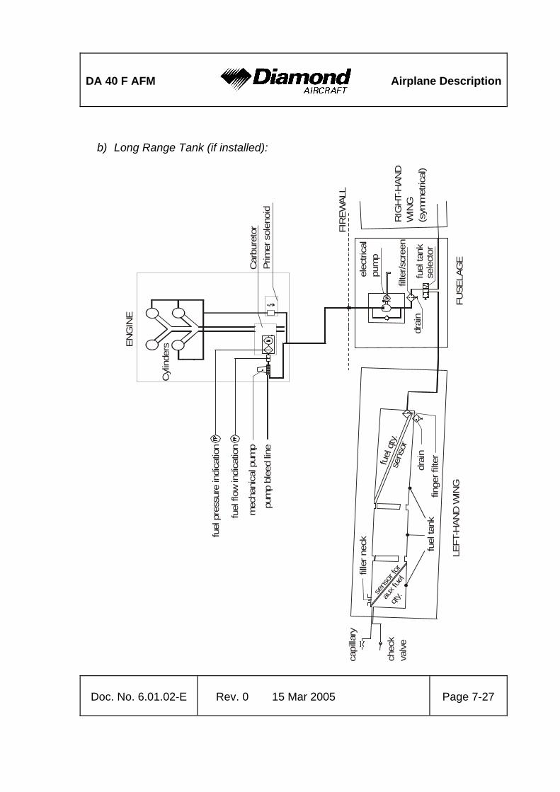
DA 40 F AFM
Airplane Description
Doc. No. 6.01.02-E Rev. 0 15 Mar 2005 Page 7-27
b) Long Range Tank (if installed):
capi
llary
chec
kva
lve
LEFT
-HAN
D W
ING
fille
r nec
k
drai
nfin
ger f
ilter
FUSE
LAG
E
drai
n
elec
trica
lpu
mp
filte
r/scr
een
fuel
tank
sele
ctor
RIG
HT-
HAN
DW
ING
(sym
met
rical
)
FIR
EWAL
L
sens
or fo
r
aux f
uel
qty.
fuel
qty.
sens
or
fuel
tank
ENG
INE
fuel
pre
ssur
e in
dica
tion
fuel
flow
indi
catio
n
pum
p bl
eed
line
mec
hani
cal p
ump
Cyl
inde
rs
Car
bure
tor
Prim
er s
olen
oid

Airplane Description
DA 40 F AFM
Page 7-28 15 Mar 2005 Rev. 0 Doc. No. 6.01.02-E
Fuel pumps
The fuel system is equipped with a mechanical and an electrical fuel pump. The mechanical pump provides for the normal fuel supply.
The electrical fuel pump is provided as an auxiliary and emergency pump, which does not operate under normal circumstances. It is operated with the FUEL PUMP switch on the row of switches on the instrument panel. It is checked during engine start, and is used as a safety back-up during take-off and landing, as well as when switching fuel tanks. It is also switched on for safety in the event of a decrease in fuel pressure.
Primer system
The engine is equipped with a primer system. By pushing the primer button in the cockpit a solenoid valve is opened and fuel is pumped into three cylinders. On the fourth cylinder the MAP sensor is installed.
The primer system will only operate with the electrical fuel pump switched on.
CAUTION The primer system is not intended for operation in flight.

DA 40 F AFM
Airplane Description
Doc. No. 6.01.02-E Rev. 0 15 Mar 2005 Page 7-29
Fuel tank selector
The fuel tank selector is situated on the center console. Its positions are LEFT (tank), RIGHT (tank) and OFF. The OFF position is reached by turning the selector to the right while pulling up the safety catch of the fuel tank selector. This is to ensure that an OFF selection is not made unintentionally.
a) Standard Tank:
F u e l S e l e c t o r
LEFT
OFF
76 l20 US gal. 20 US gal.
76 l
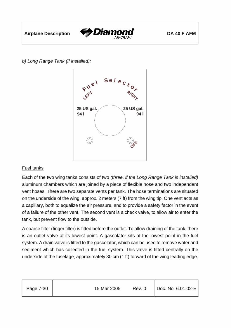
Airplane Description
DA 40 F AFM
Page 7-30 15 Mar 2005 Rev. 0 Doc. No. 6.01.02-E
b) Long Range Tank (if installed):
Fu e l
S e l e c t o rLE
FT
OFF
25 US gal. 25 US gal.94 l94 l
Fuel tanks
Each of the two wing tanks consists of two (three, if the Long Range Tank is installed) aluminum chambers which are joined by a piece of flexible hose and two independent vent hoses. There are two separate vents per tank. The hose terminations are situated on the underside of the wing, approx. 2 meters (7 ft) from the wing tip. One vent acts as a capillary, both to equalize the air pressure, and to provide a safety factor in the event of a failure of the other vent. The second vent is a check valve, to allow air to enter the tank, but prevent flow to the outside.
A coarse filter (finger filter) is fitted before the outlet. To allow draining of the tank, there is an outlet valve at its lowest point. A gascolator sits at the lowest point in the fuel system. A drain valve is fitted to the gascolator, which can be used to remove water and sediment which has collected in the fuel system. This valve is fitted centrally on the underside of the fuselage, approximately 30 cm (1 ft) forward of the wing leading edge.

DA 40 F AFM
Airplane Description
Doc. No. 6.01.02-E Rev. 0 15 Mar 2005 Page 7-31
Fuel quantity indication
a) Standard Tank:
A capacity probe ascertains fuel quantity in the tank. When the fuel quantity indicator reads zero, only the unusable fuel remains in the tank. The total capacity of each tank is 20 US gal, the maximum quantity that can be indicated is 17 US gal. Up to an actual quantity of 17 US gal the indication is correct. At an actual quantity above 17 US gal the indication remains at 17 US gal.
NOTE When the fuel quantity indicator reads 17 US gal, the correct fuel quantity must be determined with the fuel quantity measuring device. If this measurement is not carried out, the fuel quantity available for flight planning is 17 US gal and the fuel quantity that must be assumed for mass and CG calculations is 20 US gal.
b) Long Range Tank (if installed):
To determine the fuel quantity in the larger tanks an additional capacity probe is installed in each wing tank (LH / RH). When the fuel quantity indicator reads zero, only the unusable fuel remains in the tank. The usable capacity of each tank is 25 US gal (approximately 94 liters).
Fuel quantities up to 16 US gal (approximately 60 liters) in each wing tank (LH / RH) are measured by the standard sensors and indicated on the fuel quantity indicator either on the left or right side in 1 US gal (approximately 4 liters) increments.

Airplane Description
DA 40 F AFM
Page 7-32 15 Mar 2005 Rev. 0 Doc. No. 6.01.02-E
Fuel quantities between 16 US gal (approximately 60 liters) and 25 US gal (approximately 94 liters) are measured by additional sensors and indicated in the center of the fuel quantity indicator. The indication increments are 3 US gal (approximately 11 liters) between 0 and 3 US gal (approximately 11 liters) and 1 US gal (approximately 4 liters) between 3 US gal (approximately 11 liters) and 9 US gal (approximately 34 liters). Which side (LH / RH) is being indicated depends on the position of the AUX FUEL QTY. switch (refer to Section 7.4 - INSTRUMENT PANEL). The indication on the left and right side of the instrument (from 0 US gal to 16 US gal (approximately 60 liters) will not be affected.
The actual total fuel quantity in each wing tank is the sum of the individual indications.
CAUTION After selecting a fuel tank with the AUX FUEL QTY. switch, the fuel quantity indication will be incorrect for 2 minutes.
Additional fuel quantity indication between 16 US gal (approximately 60 liters) and 25 US gal (approximately 94 liters) of the wing tank selected with the AUX FUEL QTY. switch:

DA 40 F AFM
Airplane Description
Doc. No. 6.01.02-E Rev. 0 15 Mar 2005 Page 7-33
Fuel quantity measuring device
The fuel quantity measuring device allows the fuel quantity in the tank to be determined during the pre-flight inspection. It functions according to the principle of communicating containers. The fuel quantity measuring device has a recess which fits the airfoil of the wing. With this recess the device is held against the stall strip at the leading edge of the wing. The exact position is marked by a bore in the stall strip. Then the metal connector is pressed against the drain of the tank. The amount of fuel in the tank can now be read off from the vertical ascending pipe.
For an exact indication the airplane must stand on a horizontal ground.
The designated place for the fuel quantity measuring device is the bag on the rear side of the pilot seat.

Airplane Description
DA 40 F AFM
Page 7-34 15 Mar 2005 Rev. 0 Doc. No. 6.01.02-E
a) Standard Tank: b) Long Range Tank (if installed):
unusablefuel
aero
plan
e
on
leve
l grou
ndun
itin
u.s.
gallo
ns
1
2
3
4
5
6
7
8
9
10
11
12
15
13
14
17
16
18
22
20
19
21
23
24
25

DA 40 F AFM
Airplane Description
Doc. No. 6.01.02-E Rev. 0 15 Mar 2005 Page 7-35
7.11 ELECTRICAL SYSTEM
VOLT
AG
E R
EGU
LATO
RM
AIN
BU
SA
NN
UN
.AV
ION
IC B
US
ALT
. PR
OT.
ALT
. CO
NT.
ALT
.
MA
IN T
IE
ALT
ALT
ERN
ATO
R C
UR
REN
T SE
NSO
R
STA
RT
STA
RT
BAT
T
BAT
T
BAT
TEX
TER
NA
L PO
WER
BAT
TERY
24 V
11 A
MP
HR
S
STA
RTE
R16
0 A
ALT
ERN
ATO
R28
V /
70 A
OVE
R-
VOLT
AG
EPR
OTE
CTI
ON
AVIO
NIC
BU
S
ESSE
NTI
AL
AVIO
NIC
BU
S
ESS
TIE
ESS
AVIO
NIC
ESS
BU
S
MA
STER
CO
NTR
OLAV
ION
IC
ESSE
NTI
AL
BU
S
Sim
plifi
ed w
iring

Airplane Description
DA 40 F AFM
Page 7-36 15 Mar 2005 Rev. 0 Doc. No. 6.01.02-E
7.11.1 GENERAL
The DA 40 F has 28 Volt DC system, which can be sub-divided into:
- Power generation
- Storage
- Distribution
- Consumers
Power generation
The 70 ampère alternator (generator) is mounted on the front of the engine. It is driven by a V-belt, and charges the battery. In the event of alternator failure, the battery provides the system with electrical energy. Given the provision of these two independent sources of electrical power, the complete failure of the electrical system is extremely unlikely.
Storage
Power is stored in an 11 ampère-hour lead-acid battery, which is mounted in the right-hand side of the engine compartment. The battery is connected to the airplane electrical system via the main (70 ampère) circuit breaker.
In addition, a non-rechargeable dry battery is installed in the IFR model as a further source of power for the attitude gyro (artificial horizon) and the flood light. When the emergency switch is set to ON, these two systems are supplied with power for 1 hour and 30 minutes, independent of all other electrical consumers. During each 100 hour inspection, this battery is checked for proper functioning. Every 2 years or after use (broken seal on the switch) the battery cells must be replaced.

DA 40 F AFM
Airplane Description
Doc. No. 6.01.02-E Rev. 0 15 Mar 2005 Page 7-37
Distribution
Electrical power is distributed via the 'Main Bus' and the 'Essential Bus'.
Master switch (ALT/BAT)
The 'Master Switch' is divided into a 'Master Switch (ALT)' on the left and a 'Master Switch (BAT)' on the right. Both switches together are known as the >Master Switch=.
Consumers
The individual consumers (e.g. radio, electrical fuel pump, position lights, etc.) are connected to the main bus via automatic circuit breakers.
Designations and abbreviations used to identify the circuit breakers are explained in Section 1.5 DEFINITIONS AND ABBREVIATIONS.
Ignition
The DA 40 F is equipped with the electric start boost system SlickSTART. This system improves the start characteristics by delivering more spark energy during the engine start sequence. After engine starting the ignition is controlled by the conventional retard breaker magneto system.

Airplane Description
DA 40 F AFM
Page 7-38 15 Mar 2005 Rev. 0 Doc. No. 6.01.02-E
Voltmeter
The voltmeter displays the potential on the main bus. If the alternator is operating, the alternator voltage is shown, otherwise it is that provided by the battery.
Ammeter
The ammeter displays the current with which the alternator is being loaded.
Landing and taxi lights
Landing and taxi lights are built into the left wing, and are each operated by means of a switch (LANDING, TAXI) on the row of switches on the instrument panel.
Position and strobe lights
Combined position and strobe lights (anti collision lights) are installed on both wing tips. Each system is operated by a switch (POSITION, STROBE) on the row of switches on the instrument panel.
Flood light
A two-dimensional light emitter is mounted above the instrument panel. It illuminates the instrument panel as well as all levers, switches, etc. With a rotary button (FLOOD) in the left-hand section of the instrument panel the flood light is switched on and its brightness is adjusted.
Instrument lighting
With a rotary button (INSTRUMENT) in the left-hand section of the instrument panel the internal lighting of the instruments is switched on and its brightness is adjusted.

DA 40 F AFM
Airplane Description
Doc. No. 6.01.02-E Rev. 0 15 Mar 2005 Page 7-39
Pitot heating
The Pitot probe, which provides measurement for the Pitot-static system, is electrically heated. The heating is activated with a switch (PITOT) on the row of switches on the instrument panel. The temperature is automatically kept constant by means of a thermal switch on the Pitot probe, and as an additional safety measure a thermal fuse is built in. If this thermal fuse is activated, the Pitot heating can no longer be switched on, and the Pitot heating caution will be displayed. In this case the system should be serviced.
NOTE The Pitot heating caution will also be displayed whenever the Pitot heating system is switched OFF.

Airplane Description
DA 40 F AFM
Page 7-40 15 Mar 2005 Rev. 0 Doc. No. 6.01.02-E
7.11.2 WHITE WIRE ANNUNCIATOR PANEL
(WARNING, CAUTION AND STATUS LIGHTS)
Testing the annunciator panel
In the process of the pre-flight check, proper functioning of the annunciator panel must be verified. This functional check is automatically started after switching the battery master switch ON. All lights are flashed, and the aural alert is muted. By pressing the 'acknowledge' button, the lights are extinguished, and a momentary aural alert is sounded. This test verifies functionality of the microprocessor, the lights, and the aural signal.
The pilot may initiate additional system tests by holding the 'acknowledge' button for 2 seconds. All lights will begin flashing, and the aural alert will sound continuously.
Warning messages
A warning is indicated by a continuous aural alert (sounded in the airplane's intercomm system), flashing of the red WARNING light, and flashing of the red warning light associated with the affected system.
By pressing the 'acknowledge' button, which is now illuminated green, the aural alert will be terminated, and the WARNING light will be extinguished. The warning light associated with the affected system will change from flashing to solid illumination.

DA 40 F AFM
Airplane Description
Doc. No. 6.01.02-E Rev. 0 15 Mar 2005 Page 7-41
Caution messages
A caution is indicated by a momentary aural alert (sounded in the airplane's intercomm system), flashing of the amber CAUTION light, and flashing of the amber caution light associated with the affected system.
By pressing the 'acknowledge' button, which is now illuminated green, the CAUTION light will be extinguished. The caution light associated with the affected system will change from flashing to solid illumination.
The LOW FUEL caution message is displayed in a slightly different manner (extended functionality), which is described below.
Alternator warning message (ALTERNATOR)
The alternator warning message is displayed on alternator failure. The only remaining source of electrical power is the battery.
The procedure to be followed upon alternator warning is given in 3.7.2 FAILURES IN THE ELECTRICAL SYSTEM.
Low voltage caution message (LOW VOLTS)
The low voltage caution message is displayed when the on-board voltage drops below 24 volts. It is terminated when the voltage exceeds 25 volts again.
The procedure to be followed upon low voltage caution is given in 4B.3 FAILURES IN THE ELECTRICAL SYSTEM.
Fuel pressure warning message (FUEL PRESS)
The fuel pressure warning message is displayed when the fuel pressure drops below 1 psi.

Airplane Description
DA 40 F AFM
Page 7-42 15 Mar 2005 Rev. 0 Doc. No. 6.01.02-E
Low fuel caution message (LOW FUEL)
As soon as the amount of usable fuel in one tank is less than 3 US gal ("1 US gal), a caution message is displayed in the usual manner (momentary aural alert, flashing CAUTION light, flashing LOW FUEL caution light). Termination of the message is also done as usual ('acknowledge', CAUTION light is extinguished, LOW FUEL caution light changes to solid illumination).
As soon as the amount of usable fuel in the second tank is also less than 3 US gal ("1 US gal), a caution message is displayed in a different manner. A continuous aural alert is sounded in the airplane's intercomm system, the amber CAUTION light is flashed, and the amber LOW FUEL caution light is flashed.
By pressing the 'acknowledge' button, which is now illuminated green, the aural alert will be terminated, and the CAUTION light will be extinguished. The LOW FUEL caution light will continue to be flashed.
The indication is calibrated for straight and level flight. The caution message may be triggered during turns which are flown with slip, or while taxiing in curves.
Oil pressure warning message (OIL PRESS)
The oil pressure warning message is displayed when the oil pressure drops below 25 psi.
The procedure to be followed upon oil pressure warning is given in 3.2.3 ENGINE PROBLEMS IN FLIGHT.
Door warning message (DOORS)
The door warning message is displayed when the front canopy and/or the rear door is not closed and locked.

DA 40 F AFM
Airplane Description
Doc. No. 6.01.02-E Rev. 0 15 Mar 2005 Page 7-43
Starter warning message (START)
The starter warning message is displayed when the connection between the starter motor and the engine has not been broken. This occurs when the pinion of the starter motor remains engaged with the propeller flywheel.
Furthermore, the START warning light is illuminated continuously as long as the starter is being operated. In this case the WARNING light and the aural alert will not be activated.
The procedure to be followed upon starter warning is given in 3.7.2 FAILURES IN THE ELECTRICAL SYSTEM.
Pitot heating caution message (PITOT)
The Pitot heating caution message is displayed when the Pitot heating is not switched on, or when there is a failure of the Pitot heating system.
Prolonged operation of the Pitot heating on the ground can also cause the Pitot heating caution message to be displayed. In this case it indicates the activation of the thermal switch, which prevents overheating of the Pitot heating system on the ground. This is a normal function of the system. After a cooling period, the heating system will be switched on again automatically.
Trim failure warning message (TRIM FAIL)
The White Wire annunciator panel is prepared for the installation of an autopilot in the DA 40 F. When the autopilot is installed and ready for operation, this warning message indicates a failure of the automatic trim system of the autopilot. For further details, refer to the Supplement to the AFM for the autopilot (if installed).
Unused lights
The White Wire annunciator panel has two lights for possible future use. These lights are currently unused.

Airplane Description
DA 40 F AFM
Page 7-44 15 Mar 2005 Rev. 0 Doc. No. 6.01.02-E
7.12 PITOT-STATIC SYSTEM
Total pressure is measured at the leading edge of a Pitot probe under the left wing. Static pressure is measured at two orifices at lower and rear edges of the same probe. To protect against dirt and condensation there are filters in the system, which are accessible from the wing root. The Pitot probe is electrically heated.
In addition an alternate static valve is installed on the underside of the instrument panel. With this valve, the static pressure in the cabin can be used as static pressure source in the event of a failure of the Pitot-static system.
7.13 STALL WARNING
If airspeed drops below approximately 1.1 times the stalling speed, the stall warning horn, located in the instrument panel, will sound. The horn becomes progressively louder the closer one gets to stalling speed. Suction at an orifice on the left wing leading edge activates the horn via a hose. The orifice for the stall warning in the left wing is marked by a red ring.
7.14 AVIONICS
The radio and navigation equipment is located in the central part of the instrument panel. A transmit switch for the radio is mounted on the end of each control stick. There are connection facilities for up to 4 headsets between the front seats.

DA 40 F AFM
Handling
Doc. No. 6.01.02-E Rev. 0 15 Mar 2005 Page 8-1
CHAPTER 8
AIRPLANE HANDLING, CARE AND MAINTENANCE
Page 8.1 INTRODUCTION............................................................................................... 8-2 8.2 AIRPLANE INSPECTION INTERVALS............................................................. 8-2 8.3 AIRPLANE ALTERATIONS OR REPAIRS........................................................ 8-3 8.4 GROUND HANDLING / ROAD TRANSPORT................................................... 8-3
8.4.1 GROUND HANDLING WITHOUT TOW BAR ..............................................8-3 8.4.2 GROUND HANDLING WITH TOW BAR......................................................8-4 8.4.3 PARKING.....................................................................................................8-6 8.4.4 MOORING ...................................................................................................8-8 8.4.5 JACKING .....................................................................................................8-8 8.4.6 ALIGNMENT................................................................................................8-8 8.4.7 ROAD TRANSPORT ...................................................................................8-9
8.5 CLEANING AND CARE....................................................................................8-10 8.5.1 PAINTED SURFACES...............................................................................8-10 8.5.2 CANOPY AND REAR DOOR.....................................................................8-11 8.5.3 PROPELLER .............................................................................................8-11 8.5.4 ENGINE .....................................................................................................8-11 8.5.5 INTERIOR SURFACES .............................................................................8-11

Handling
DA 40 F AFM
Page 8-2 15 Mar 2005 Rev. 0 Doc. No. 6.01.02-E
8.1 INTRODUCTION
Chapter 8 contains the manufacturer's recommended procedures for proper ground handling and servicing of the airplane. The Airplane Maintenance Manual (Doc. No. 6.02.01) lists certain inspection and maintenance requirements which must be followed if the airplane is to retain a new plane performance and reliability.
8.2 AIRPLANE INSPECTION INTERVALS
For maintenance work on engine and propeller, the currently effective Operator's Manuals, Service Instructions, Service Letters and Service Bulletins of Lycoming and Sensenich propeller must be followed. For airframe inspections, the currently effective checklists/manuals of the manufacturer must be followed.
CAUTION Unscheduled maintenance checks are required after:
- hard landings
- propeller strike
- engine fire
- lighting strike
- occurrence of other malfunctions and damage
Unscheduled maintenance checks are described in the Airplane Maintenance Manual (Doc. No. 6.02.01; Section 05-50).

DA 40 F AFM
Handling
Doc. No. 6.01.02-E Rev. 0 15 Mar 2005 Page 8-3
8.3 AIRPLANE ALTERATIONS OR REPAIRS
Alterations or repairs of the airplane may be carried out only according to the Airplane Maintenance Manual, Doc. No. 6.02.01, and only by authorized personnel.
8.4 GROUND HANDLING / ROAD TRANSPORT
8.4.1 GROUND HANDLING WITHOUT TOW BAR
During forward traversing the nose wheel will follow the movement of the airplane. Change in direction is achieved by pulling on the propeller near the spinner. To traverse in the rear direction, the tail section of the airplane should be pushed down until the nose wheel is clear of the ground. This method can also be used to turn the airplane around its main landing gear.

Handling
DA 40 F AFM
Page 8-4 15 Mar 2005 Rev. 0 Doc. No. 6.01.02-E
8.4.2 GROUND HANDLING WITH TOW BAR
For pushing or pulling the airplane on the ground, it is recommended to use the tow bar which is available from the manufacturer. The tow bar is bent apart and engaged in the appropriate holes in the nose wheel fairing as shown on the picture below. The arresting knob must be fully engaged.

DA 40 F AFM
Handling
Doc. No. 6.01.02-E Rev. 0 15 Mar 2005 Page 8-5
WARNING The tow bar must be removed before starting the engine.
CAUTION The tow bar may only be used for moving the airplane on the ground by hand. After moving the airplane, the tow bar must be removed.
NOTE When moving the airplane rearward, the tow bar must be held firmly to prevent abrupt sideward deflection of the nose wheel.

Handling
DA 40 F AFM
Page 8-6 15 Mar 2005 Rev. 0 Doc. No. 6.01.02-E
8.4.3 PARKING
For short term parking, the airplane must be positioned into the wind, the parking brake must be engaged and the wing flaps must be in the retracted position. For extended and unattended parking, as well as in unpredictable wind conditions, the airplane must be anchored to the ground or placed in a hangar. Parking in a hangar is recommended.
Control surfaces gust lock
The manufacturer offers a control surfaces gust lock which can be used to block the primary controls. It is recommended that the control surfaces gust lock be used when parking outdoors, because otherwise the control surfaces can hit the stops in strong tail wind. This can lead to excessive wear or damage.
WARNING The control surfaces gust lock must be removed before flight.
The control surfaces gust lock is installed as follows:
1. Move the rudder pedals fully rearward.
2. Engage the control surfaces gust lock with the pedals.
3. Engage the stick, wrap straps around stick once.
4. Attach the locks and tighten the straps.
For removal, reverse the sequence.

DA 40 F AFM
Handling
Doc. No. 6.01.02-E Rev. 0 15 Mar 2005 Page 8-7
Handling
DA 40 F AFM
Page 8-8 15 Mar 2005 Rev. 0 Doc. No. 6.01.02-E
8.4.4 MOORING
The tail fin of the airplane has a hole which can be used to tie-down the airplane to the ground. Also on each wing near the wing tip, an eyelet with a metric M8 thread can be installed and used as tie-down points.
8.4.5 JACKING
The DA 40 F can be jacked at the two jackpoints located on the lower side of the fuselage's LH and RH root ribs as well as at the tail fin.
8.4.6 ALIGNMENT
For alignment push down on the tail section at the fuselage/vertical tail junction until the nose wheel is clear of the ground. With the nose wheel free, the DA 40 F can be turned around the main landing gear. After turning the airplane into the correct position, release the tail section until the nose wheel is back on the ground.

DA 40 F AFM
Handling
Doc. No. 6.01.02-E Rev. 0 15 Mar 2005 Page 8-9
8.4.7 ROAD TRANSPORT
For transporting the airplane on the road it is recommended that an open trailer be used. All airplane components must be stored on a cushioned surface and secured to avoid any movement during transportation.
1. Fuselage:
The fuselage should stand on the main and nose landing gear. It must be ensured that the fuselage will not move in a forward, backward or upward direction. Furthermore, it must be ensured that the propeller has sufficient clearance so that it cannot be damaged due to fuselage movement during transportation.
2. Wings:
For transportation, both wings must be removed from the fuselage. To avoid any damage, the wings are stored in an upright position on the leading edge with the root rib area positioned on an upholstered profiled surface with a width of at least 400 mm (1.3 ft). The outside wing area (approximately 3 m (10 ft) from the root rib area) is placed on an upholstered profiled surface with a minimum width of 300 mm (1 ft).
The wings must be secured to avoid any sliding movement to the rear.
3. Horizontal stabilizer:
The horizontal stabilizer is stored flat on the trailer and secured with straps, or in an upright position sitting on the leading edge on a profiled surface. All storing surfaces must be upholstered with felt or cellular rubber.

Handling
DA 40 F AFM
Page 8-10 15 Mar 2005 Rev. 0 Doc. No. 6.01.02-E
8.5 CLEANING AND CARE
CAUTION The airplane must be kept clean. The bright surface prevents the structure from overheating.
CAUTION Excessive dirt deteriorates the flight performance.
8.5.1 PAINTED SURFACES
The entire surface of the airplane is painted with a white weatherproof two component paint. Nevertheless, the airplane should be protected against moisture and dampness. The airplane should not be stored outdoors for long periods of time. Moisture that has penetrated must be removed by storing the affected parts in a dry place and turning them over several times.
Dirt, insects, etc. can be removed with water alone and if necessary with a mild detergent. An automotive paint cleaner can be used for stubborn spots. For best results, clean the airplane after the day's flying is ended, so that the dirt will not become ingrained.
Oil stains, exhaust stains, etc. on the lower fuselage skin can be removed with a cold detergent. Before starting, ensure that the detergent does not affect the surface finish. Use commercial automotive preservatives without silicone additives to conserve the paint finish.

DA 40 F AFM
Handling
Doc. No. 6.01.02-E Rev. 0 15 Mar 2005 Page 8-11
8.5.2 CANOPY AND REAR DOOR
The canopy and rear door should be cleaned with 'Plexiklar' or any other acrylic glass detergent if available; otherwise use lukewarm water. Final cleaning should be done with a clean piece of chamois-leather or soft cloth. Never rub or polish dry acrylic glass.
8.5.3 PROPELLER
Damage and malfunctions during operation must be inspected by authorized personnel.
Should doubts arise, an appropriately rated inspector must be consulted.
8.5.4 ENGINE
Engine cleaning is part of the scheduled inspections.
8.5.5 INTERIOR SURFACES
The interior should be cleaned using a vacuum cleaner. All loose items (pens, bags etc.) should be removed or properly stored and secured.
All instruments can be cleaned using a soft dry cloth, plastic surfaces should be wiped clean using a damp cloth without any cleaning agents.

Handling
DA 40 F AFM
Page 8-12 15 Mar 2005 Rev. 0 Doc. No. 6.01.02-E
Intentionally left blank

DA 40 F AFM
Supplements
Doc. No. 6.01.02-E Rev. 0 15 Mar 2005 Page 9-1
CHAPTER 9
SUPPLEMENTS Page
9.1 INTRODUCTION.............................................................................................. 9-2 9.2 LIST OF SUPPLEMENTS ................................................................................ 9-3

Supplements
DA 40 F AFM
Page 9-2 15 Mar 2005 Rev. 0 Doc. No. 6.01.02-E
9.1 INTRODUCTION
Chapter 9 contains information concerning additional (optional) equipment of the DA 40 F.
Unless otherwise stated, the procedures given in the Supplements must be applied in addition to the procedures given in the main part of the Airplane Flight Manual.
All approved supplements are listed in the List of Supplements in this Chapter.
The Airplane Flight Manual contains exactly those Supplements which correspond to the installed equipment according to the Equipment Inventory of Section 6.5.

DA 40 F AFM
Supplements
Doc. No. 6.01.02-E Rev. 0 15 Mar 2005 Page 9-3
9.2 LIST OF SUPPLEMENTS
Airplane S/N: Registration: Date:
applicable Sup.
No. Title
Rev.
No. Date
YES NO
A2
Intercomm System,
Model PM 1000 II
PS Engineering, Inc.
2 15-Mar-2005 9 9
A11 Compass System, KCS 55A
Bendix/King 4 15-Mar-2005 9 9
A12 Transponder, KT 76C
Bendix/King 2 15-Mar-2005 9 9
A13 Autopilot, KAP 140
Bendix/King 2 15-Mar-2005 9 9
A14 GPS, KLN 94 (IFR Operation)
Bendix/King 3 15-Mar-2005 9 9
A15
GPS Annunciation Control Unit,
MD 41
Mid-Continent
2 15-Mar-2005 9 9
A19 Transponder, GTX 327
Garmin 1 15-Mar-2005 9 9
A20
Course Deviation Indicator
GI 106A
Garmin
1 15-Mar-2005 9 9

Supplements
DA 40 F AFM
Page 9-4 15 Mar 2005 Rev. 0 Doc. No. 6.01.02-E
Airplane S/N: Registration: Date:
applicable Sup.
No. Title
Rev.
No. Date
YES NO
A25
Audio Panel
GMA 340
VFR
2 15-Mar-2005 9 9
A26
COM/NAV/GPS
GNS 430
VFR
1 15-Mar-2005 9 9
E2
Attitude Indicator,
AIM 1100-28L(0F)
BF Goodrich
2 15-Mar-2005 9 9
E3
Attitude Indicator,
AIM 1100-28LK(0F) DIA
BF Goodrich
2 15-Mar-2005 9 9
E4
Digital Chronometer,
Model 803
Davtron
1 15-Mar-2005 9 9
S1
Emergency Locator Transmitter
Model E-01
ACK
2 15-Mar-2005 9 9


![VERSIONE SOFTWARE - manuali.eltex.bizmanuali.eltex.biz/Manuali_SHS/APSx-x-00_60_4K_r03.pdf · TAGLIA APS1 APS2 APS3 APS4 APS5 Vdc nom. [V] Da 40 a 80 Da 40 a 80 Da 40 a 80 Da 80 a](https://static.fdocuments.us/doc/165x107/5ae883f57f8b9a29049037db/versione-software-aps1-aps2-aps3-aps4-aps5-vdc-nom-v-da-40-a-80-da-40-a-80.jpg)