AIRMAIL:Alink-layerprotocolforwirelessnetworkscs610/airmail.pdf ·...
14
Transcript of AIRMAIL:Alink-layerprotocolforwirelessnetworkscs610/airmail.pdf ·...

AIRMAIL:A link-layer protocol forwireless networks
EnderAyanoglu, Sanjoy Paul, Thomas F. LaPorta,KrishanK. Sabnani andRichardD.Gitlin
AT&TBell Laboratories,Holmdel,New Jersey 07733, USA
Received 27August 1994
Abstract. This paper describes the design and performance of a link-layer protocol for indoor and outdoor wireless networks.
The protocol is asymmetric to reduce the processing load at the mobile, reliability is established by a combination of automatic
repeat request and forward error correction, and link-layer packets are transferred appropriately during handoffs. The protocol is
named AIRMAIL (AsymmetrIc Reliable Mobile Access In Link-layer). The asymmetry is needed in the design because the mobile
terminals have limited power and smaller processing capability than the base stations. The key ideas in the asymmetric protocol
design consist of placing bulk of the intelligence in the base station as opposed to placing it symmetrically, in requiring the mobile
terminal to combine several acknowledgments into a single acknowledgment to conserve power, and in designing the base stations
to send periodic status messages, while making the acknowledgment from the mobile terminal event-driven. The asymmetry in
the protocol design results in a one-third reduction of compiled code. The forward error correction technique incorporates three
levels of channel coding which interact adaptively. The motivation for using a combination of forward error correction and
link-layer retransmissions is to obtain better performance in terms of end-to-end throughput and latency by correcting errors in
an unreliable wireless channel in addition to end-to-end correction rather than by correcting errors only by end-to-end retransmis-
sions. The coding overhead is changed adaptively so that bandwidth expansion due to forward error correction is minimized.
Integrity of the link during handoffs (in the face of mobility) is handled by window management and state transfer. The protocol
has been implemented. Experimental performance results based on the implementation are presented.
1. Introduction
Most data link-layer protocols in existence today
have been designed for conventional networks: low-
speed landline networks based on voiceband modems
which have fixed and relatively low error rates, LANs
with very low error rates, the satellite channel with a
large propagation delay, or high-speed networks with
extremely low error rates and relatively large propaga-
tion delays (with respect to the packet size). The mobile
wireless channel has different characteristics than these
conventional networks: the error rate can be very high
and it is highly variable, and the propagation delay with
respect to the packet sizes is small. With the increasing
popularity of wireless communication, in the form of
outdoor cellular communications with small bandwidth,
or indoor wireless LAN with large bandwidth, there is a
growing need for new link-layer protocols to accommo-
date the specific properties of the wireless channel in an
efficient way so that a wireless terminal with better per-
formance, lower power, and smaller size can be designed
(see, e.g., [8,11]). In this paper we propose such a proto-
col. We envision a network architecture which has a
wired network as its backbone with base stations on it
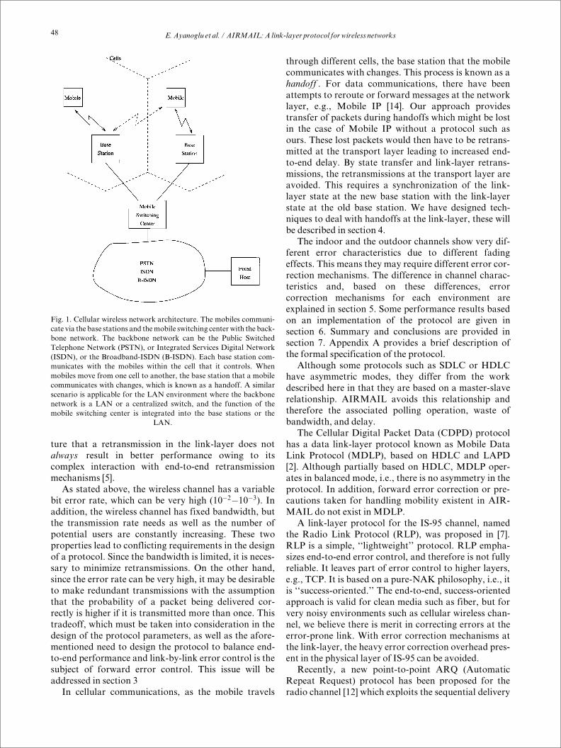
acting as access points for the mobile terminals (Fig. 1).
Mobile terminals communicate through the base sta-
tions with other hosts. In the context of this architecture,
a wireless channel refers to the channel between a wire-
less terminal and a base station. Our emphasis through-
out the paper will be on the link between the base station
and amobile terminal.
The configuration with a wireless channel between a
base station (which is wired to the backbone network)
and a mobile terminal (which has no wired connection)
is inherently asymmetric in nature. The asymmetry can
be attributed to the fact that the mobile terminal has
limited power and smaller processing capability than the
base station. In order to accommodate this asymmetry,
we propose to put as much intelligence as possible in
terms of processing in the base stations and make the
mobile terminals relatively dumb. This issue will be
addressed in section 2.
Because of the effects of fading, interference and
mobility, the error rate incurred in a mobile wireless
channel is often very high. This has two effects. First, in
current systems, end-to-end protocols must recover
from these errors, often using retransmission timers.
These timers are typically set to values on the order of
seconds to allow for variable network delays. This
causes the recovery time of an error that occurs on a
wireless channel to be long. Secondly, losses incurred
on the wireless channel trigger the end-to-end transmit-
ters to decrease the window size and increase the dura-
tion of the retransmission timers as observed by
Caceres and Iftode in [3]. This leads to lower through-
put and higher latency. Therefore, correcting errors at
the link-layer in addition to end-to-end correction will
result in better performance compared to only end-to-
end correction. However, there is evidence in the litera-
WirelessNetworks 1 (1995) 47^60 47
Ä J.C. Baltzer AG, Science Publishers
ture that a retransmission in the link-layer does not
always result in better performance owing to its
complex interaction with end-to-end retransmission
mechanisms [5].
As stated above, the wireless channel has a variable
bit error rate, which can be very high (10
ÿ2
ÿ10
ÿ3
). In
addition, the wireless channel has fixed bandwidth, but
the transmission rate needs as well as the number of
potential users are constantly increasing. These two
properties lead to conflicting requirements in the design
of a protocol. Since the bandwidth is limited, it is neces-
sary to minimize retransmissions. On the other hand,
since the error rate can be very high, it may be desirable
to make redundant transmissions with the assumption
that the probability of a packet being delivered cor-
rectly is higher if it is transmitted more than once. This
tradeoff, which must be taken into consideration in the
design of the protocol parameters, as well as the afore-
mentioned need to design the protocol to balance end-
to-end performance and link-by-link error control is the
subject of forward error control. This issue will be
addressed in section 3
In cellular communications, as the mobile travels
through different cells, the base station that the mobile
communicates with changes. This process is known as a
handoff . For data communications, there have been
attempts to reroute or forward messages at the network
layer, e.g., Mobile IP [14]. Our approach provides
transfer of packets during handoffs which might be lost
in the case of Mobile IP without a protocol such as
ours. These lost packets would then have to be retrans-
mitted at the transport layer leading to increased end-
to-end delay. By state transfer and link-layer retrans-
missions, the retransmissions at the transport layer are
avoided. This requires a synchronization of the link-
layer state at the new base station with the link-layer
state at the old base station. We have designed tech-
niques to deal with handoffs at the link-layer, these will
be described in section 4.
The indoor and the outdoor channels show very dif-
ferent error characteristics due to different fading
effects. This means they may require different error cor-
rection mechanisms. The difference in channel charac-
teristics and, based on these differences, error
correction mechanisms for each environment are
explained in section 5. Some performance results based
on an implementation of the protocol are given in
section 6. Summary and conclusions are provided in
section 7. Appendix A provides a brief description of
the formal specification of the protocol.
Although some protocols such as SDLC or HDLC
have asymmetric modes, they differ from the work
described here in that they are based on a master-slave
relationship. AIRMAIL avoids this relationship and
therefore the associated polling operation, waste of
bandwidth, and delay.
The Cellular Digital Packet Data (CDPD) protocol
has a data link-layer protocol known as Mobile Data
Link Protocol (MDLP), based on HDLC and LAPD
[2]. Although partially based on HDLC, MDLP oper-
ates in balanced mode, i.e., there is no asymmetry in the
protocol. In addition, forward error correction or pre-
cautions taken for handling mobility existent in AIR-
MAIL do not exist in MDLP.
A link-layer protocol for the IS-95 channel, named
the Radio Link Protocol (RLP), was proposed in [7].
RLP is a simple, ``lightweight'' protocol. RLP empha-
sizes end-to-end error control, and therefore is not fully
reliable. It leaves part of error control to higher layers,
e.g., TCP. It is based on a pure-NAK philosophy, i.e., it
is ``success-oriented.'' The end-to-end, success-oriented
approach is valid for clean media such as fiber, but for
very noisy environments such as cellular wireless chan-
nel, we believe there is merit in correcting errors at the
error-prone link. With error correction mechanisms at
the link-layer, the heavy error correction overhead pres-
ent in the physical layer of IS-95 can be avoided.
Recently, a new point-to-point ARQ (Automatic
Repeat Request) protocol has been proposed for the
radio channel [12] which exploits the sequential delivery
Fig. 1. Cellular wireless network architecture. The mobiles communi-
cate via the base stations and themobile switching center with the back-
bone network. The backbone network can be the Public Switched
Telephone Network (PSTN), or Integrated Services Digital Network
(ISDN), or the Broadband-ISDN (B-ISDN). Each base station com-
municates with the mobiles within the cell that it controls. When
mobiles move from one cell to another, the base station that a mobile
communicates with changes, which is known as a handoff. A similar
scenario is applicable for the LAN environment where the backbone
network is a LAN or a centralized switch, and the function of the
mobile switching center is integrated into the base stations or the
LAN.
E.Ayanoglu et al. / AIRMAIL:A link-layer protocol for wireless networks
48

of packets in a wireless link. However, it assumes cir-
cuit-mode data, while we assume packet-mode data.
Further, [12] does not have any of the unique properties
of our protocol, namely, asymmetry, adaptive forward
error correction, and mobility management.
We describe the asymmetric features of the basic
protocol first. We then describe the forward error
correction techniques and show how forward error cor-
rection and the retransmission mechanisms of the
asymmetric protocol can be combined to obtain relia-
bility. Then, how mobility is taken care of in AIRMAIL
is described. These descriptions are followed by simula-
tion and performance measurement results. The basic
asymmetric protocol which relies only on ARQ tech-
niques is described next.
2. Asymmetry
The key ideas in incorporating asymmetry affect the
ARQ error control andwindow-based flow control tech-
niques used in AIRMAIL. These are summarized
below.
1. Timers are always at the base station regardless of
whether it is transmitting or receiving. Thus the intel-
ligence in terms of maintaining timers, processing
complex status messages andmost importantly, mak-
ing decisions resides in the base station.
2. The base station receiver sends its status to a mobile
transmitter periodically , as in the SNR protocol [13].
The justification for using periodic status messages is
to reduce the dependence on the error-prone medium.
In particular, if the wireless channel is bad and the
base station does not receive packets, it can still send
statusmessages, because sending of statusmessages is
triggered by the timeout signal of a local timer and
not by the event of receiving a packet. Also, if a status
message gets lost, a subsequent status message will
shortly follow.
Note that the period of sending status messages
should be optimized so as not to waste much band-
width for control information while at the same time
offsetting the effect of a noisy channel.
3. The mobile receiver does not send its status to the
base transmitter periodically because of its power
constraint. These statusmessages are event-driven.
4. The mobile receiver combines several status messages
into one status message to conserve power. That is,
the mobile terminal does not send a status message
after receiving each packet. Rather it sends a status
message after receiving a block (a set of packets).
However, there is a trade-off between wasting power
and increasing latency.
Thus a mobile terminal transmits packets , but
does not send an acknowledgment after receiving
each packet. It waits for receiving a whole block
before sending out a statusmessage.
The following subsections provide more detail on
how repeat requests and window-based flow control are
handled in AIRMAIL.
2.1. From Mobile Transmitter (MT) to Base Receiver
(BR)
The steps involved in providing repeat requests and
flow control fromMT toBR are listed below (Fig. 2):
1. MT transmits new packets continuously until a maxi-
mum transmit buffer size is reached (maximumbuffer
size is computed using a multiple of the round-trip
delay), a retransmission request (status message noti-
fying loss/corruption of a packet) is received, or it
has no more data to transmit. Retransmission has
priority over transmission of a new packet.WhenMT
has no more to transmit, it sets a bit in the packet
header of the last packet. This bit is referred to as the
e-bit in subsequent sections of the paper.
2. BR transmits status messages periodically to MT.
This is similar to periodic state exchange in the SNR
protocol [13] except that state is not exchanged and
that the status messages in this protocol do not con-
tain information regarding how much buffer space is
available in the receiver as in the SNR protocol. The
periodicity is maintained using a status timer which
expires after a given interval and is restarted after a
status message is sent. The period is reduced when BR
Fig. 2. Data transfer fromMobile Transmitter (MT) to a Base Receiver
(BR). Messages 1 are new packets transmitted by MT. Messages 2 are
periodic statusmessages transmitted by BR.Messages 3 are retransmis-
sions of lost packets. In the figure, message 1d is lost, and retransmitted
upon receipt of the statusmessage.
E.Ayanoglu et al. / AIRMAIL:A link-layer protocol for wireless networks 49

receives a packet with the e-bit set. In such a case,
BR sends its status immediately without waiting for
the Status Timer to expire. This allows for fast
acknowledgments when small amounts of data are
being sent and quick response is themain concern.
Since MT does not send its status periodically and
it does not have a timer, a timer is needed at BR to
detect loss of packets. The concept of using a timer at
the receiver was introduced in NETBLT [4], although
in the context of a transport protocol. Also note that
BR sends its status periodically toMT, thereby incor-
porating redundancy in the error-pronemedium.
3. MT retransmits the requested packets before trans-
mitting any new packet.
If retransmissions do not reach BR, MT will not
be able to transmit any new packets after a finite per-
iod because the transmit buffer space at MT will be
exhausted. The transmit buffer size buf atMT is larger
than the window
1
to take care of loss of status mes-
sages fromBR toMT. This improves the performance
in terms of throughput and delay.
Since buf is larger than the window , MT can trans-
mit new packets longer than usual with the hope that
status messages acknowledging previously trans-
mitted packets will arrive a little later than the
expected time owing to the loss of first few status mes-
sages. This prevents idling by the transmitter. In other
words, MT anticipates opening of window or freeing
of buffer space in near future.
Buffer space atMTwill be exhausted if the forward
channel (BR to MT) is bad or the reverse channel
(MT to BR) is bad or both are bad. We argue next
that in any case such an anomaly will be reflected at
BR in the form of an unchanged status.
Consider first the case in which the reverse channel
is bad. That is, the (re)transmitted packets from MT
to BR are getting lost. In that case, the status of BR
will not change because BR is not receiving anything
from MT. If however, the forward channel is good,
the statusmessages (which are identical) fromBRwill
reach MT. In that case, MT will keep retransmitting
the packets with the expectation that the channel will
improve soon. If the channel does not improve, BR
will not receive any retransmitted packet and hence
its status will not change. The anomaly will thus be
detected at BR.
Consider next the case in which the forward chan-
nel is bad. That is, the status messages from BR to
MT are getting lost. If the status messages are lost,
MT will have no idea as to which packets are received
at BR. Thus, MT will soon run out of buffer space
and stop transmitting new packets. Not only will MT
stop transmitting new packets but it will also not
retransmit any old packet before it receives a status
message from BR. The reason for MT's not retrans-
mitting any old packet is that it does not know which
packets have been received by BR and it does not
want to retransmit indiscriminately because band-
width is expensive. Since MT stops any (re)trans-
mission, BR's status will stop changing and the anom-
alywill be detected.
Thus whether the forward channel or the reverse
channel goes bad, the anomaly will be reflected at BR
as a no change of its status. BR will drop the connec-
tion if such a situation persists for some time.
2.2. From Base Transmitter (BT) to Mobile Receiver
(MR)
The steps involved in repeat requests and flow control
fromBT toMRare listed as follows (see Fig. 3):
1. BT transmits new packets until the window closes, a
request for retransmission (which is a part of the sta-
tus message) arrives, or it has no more packets to
transmit. When BT has no more packets to transmit,
it sets the e-bit in the packet header of the last
packet.
BT starts a timer after transmitting a full block of
packets or after transmitting a packet with the e-bit
1
Throughout this paper the term window is used to represent the
number of packets that can be transmitted during a round-trip delay.
Fig. 3. Data transfer from a Base Transmitter (BT) to a Mobile Recei-
ver (MR). When BT completes the transmission of a block (1), it starts
a timer. MR transmits a bitmap of indicating which packets within a
block have been received (2) when it receives a block. IF BT does not
receive the bitmap, it sends explicit status message request (3). When
MR receives message 3, it transmits status message (4). In this figure,
there is no loss in the block 1a, but there are losses in block 1b. In addi-
tion, block acknowledgement 2b is lost. Then, BT sends explicit status
message request 3, and statusmessage 4 is transmitted.
E.Ayanoglu et al. / AIRMAIL:A link-layer protocol for wireless networks
50
set, and sends an explicit status request message
(Poll) to MR if it does not hear from MR before the
timer expires.Note the presence of timer at BT.
2. MR sends a status message after it receives a whole
block (fixed number of packets). The statusmessage is
a bitmap such that bitiindicates whether packet
i
within the given block has been received or not.
Biti� 1 indicates ``received'' while bit
i� 0 indicates
``not received.''
Note that to conserve power, MR, unlike BR
(when Base Station is in the receiving mode), does not
send status messages periodically (at fixed intervals
of time) and frequently (more than once during the
round trip time). Moreover, for the same reason, it
does not send a status message after it receives each
packet.MRwaits for either a whole block, or a packet
with the e-bit set, to arrive before sending out a status
message. This allows the mobile unit to conserve
transmission power.
3. BT retransmits the requested packets.
Note that BT selectively retransmits only the
``lost'' packets in a given block and not the whole
block.
2
This conserves bandwidth.
BT also starts the timer to detect ifMR sends a sta-
tus message acknowledging the receipt of the retrans-
mitted packet within the expected time. If not, BT
sends an explicit Poll message to MR. If the status
message from MR does not arrive before the timer
expires, BT tries again and gives up after a few
attempts ifMRdoes not respond.
The basic asymmetric protocol relies only on the
retransmission mechanism to ensure reliability. Decid-
ing whether errors are present in a packet is carried out
by means of a cyclic redundancy check. By increasing
the power of the code used for that purpose, it is possi-
ble to correct errors and avoid retransmissions. In addi-
tion, errored packets that cannot be corrected by
means of this redundancy can be corrected by addi-
tional parity packets. For real-time traffic, such as
audio and video, retranmissions are not feasible, and
forward error correction is viable for ensuring a given
quality of service. By changing the parameters of for-
ward error correction, the best channel utilization can
be achieved. These ideas are described in more detail in
the following section.
3. Forward error correction
The digital mobile channel has various sources of ran-
dom noise and deterministic interference that give rise
to errored receptions. The most dominant factors are
Rayleigh fading due to Doppler shift of the operating
frequency for mobile transceivers or mobile scatterers,
multipath interference due to reflections from natural
and man-made objects around the main transmission
path, random noise, and co-channel and adjacent chan-
nel interference. Various signal processing alternatives
are under consideration for these sources of interference,
such as equalization, space diversity, multitone trans-
mission, and forward error correction (FEC) at the phy-
sical layer. No consensus exists in the literature as to
which of these techniques can universally recover from
all sources of noise and interference. It has been gener-
ally accepted that some FEC at the physical layer is
needed to recover from noise for the outdoor channel. In
general, however, this FEC will not be able to generate
an error-free channel, and some residual error will be
propagated to the data link layer.
As is well-known, FEC techniques are sometimes
used in addition to the automatic repeat request (ARQ)
techniques at the data link layer. Various combined
techniques, known as hybrid techniques, have been sug-
gested and studied for this purpose (e.g., see [10] and
its references). Among the channels suggested for the
use of hybrid ARQ/FEC schemes is the satellite chan-
nel and the high-speed ATM channel. In both cases, the
packet size is large with respect to the propagation
delay, or in other words, the bandwidth-delay product
is high. This makes the process of requesting and receiv-
ing retransmissions take long with respect to the packet
size, and consequently reduces the protocol throughput.
Therefore FEC, by means of adding redundant packets
so that errored or ``lost'' packets can be reconstructed
based on the redundant packets and packets that are
correctly received, becomes a feasible alternative to
ARQ. The land-mobile channel does not have a large
delay-bandwidth product, and therefore, the use of
FEC at the data link-layer as suggested above may
appear to be questionable. We will address this issue in
this section, and will summarize under which circum-
stances FEC becomes useful. First, we would like to dis-
cuss possible ways of implementing FEC in a data
transmission system.
There are three possible levels FEC can be incorpo-
rated into a data transmission system.
y Bit-level FEC: This is achieved at the physical layer,
typically in hardware, by means of a DSP chip or
an application specific integrated circuit. For band-
width-limited channels, trellis coded modulation
with Viterbi decoding is used. If the channel is not
bandlimited, block or convolutional coding tech-
niques are employed. In the latter case, decoding is
by means of the Viterbi algorithm. A characteristic
of the Viterbi algorithm is that it provides a
2
This is different from the SNR protocol in which a whole block
is retransmitted. SNR protocol is designed for high-speed networks
where bandwidths is not expensive and hence retransmitting a whole
block is not a big issue. However, in wireless links, bandwidth is
expensive and hence we minimize all transmissions.
E.Ayanoglu et al. / AIRMAIL:A link-layer protocol for wireless networks 51
sequence, which is closest to the original given the
received sequence in some mathematical measure
(i.e., maximum likelihood). By definition, the Viterbi
algorithm does not provide any indication of an
uncorrectable sequence, or the number of correc-
tions, etc. Although it is possible to correlate calcu-
lated values in the algorithm with the long term
channel bit error rate, the Viterbi algorithm does not
provide a measurement of the short-term channel
error characteristics based on channel errors.
y Byte-level FEC: This is done by means of per-packet
FEC. Every packet in a data link-layer protocol car-
ries a cyclic redundancy check (CRC) field in order
to determine whether the packet is received error-
free. The same field can be used for error correction.
Most conventional data link-layer protocols use this
field for error detection only, mainly due to the com-
putational complexity of performing FEC decoding.
Recently, with the advent of more powerful proces-
sing, additional use of this field for error correction
purposes is being considered. For example, ATM
AAL 3/4 has a per-cell CRC field which is designed
to be capable of one bit error correction. In a similar
fashion, we propose replacing this field by a code
that is capable of error correction, such as the output
of a Reed-Solomon encoder. When the field size is
the same as that needed for CRC, there is no addi-
tional bandwidth or coding overhead required as
compared to an ARQ scheme, although there is an
associated increase in the probability of undetected
errors. By increasing the size of this field, the prob-
ability of undetected error and the number of packet
retransmissions needed can be reduced. Our simula-
tions indicate most blocks have a few bytes in error
for the outdoor channel, and therefore, bit- and
byte-level FEC can be highly beneficial for this envi-
ronment. Byte-level FEC has the advantage of cor-
recting only those bytes in error (as the error process
manifests itself as short bursts), and therefore has
the advantage of using the bandwidth more effi-
ciently. The interplay between these two levels of
FEC is an interesting area of research.
y Packet-level FEC: This is done by allocating some
packets in the protocol window for correction. In the
case of packets that cannot be corrected by bit-level
or byte-level FEC (or equivalently, packets that are
``lost''), these redundant packets, together with the
correctly received packets, can be used for recovery
of the lost packets without retransmissions. It is pos-
sible to add M redundant packets to N data packets,
so that as long as at least some N packets of the total
N �M data packets and redundant packets are
received, the N data packets can be recovered. This
technique is known as optimum erasure encoding-
decoding (optimum in the maximum distance sense),
and various coding methods can be employed for
this purpose. A well-known technique is Reed-Solo-
mon codes, which can be used for error correction
(positions unknown, as in byte-level FEC) or erasure
correction (positions known) [10]. When the number
of packets is 2 or 3, the diversity code [1] is more effi-
cient in terms of the size of the field the operations
are performed in. Again, with the advent of more
complicated processing, FEC methods at the packet
level are finding their way into data transmission.
For example, there is a proposal to incorporate cell-
level FEC into ATMAAL 1.
In the system we are proposing, all three levels of
FEC have their place. Our simulations have shown that
different mobile channels show different characteris-
tics. The narrowband outdoor mobile channel has a
small number of bytes in error for most of the packets
transmitted. There exists some correlation in the num-
ber of errored bytes with time. This correlation can be
exploited for estimation of the number of bytes to be in
error for the next block, and the FEC overhead can be
changed by a message from the receiver to the transmit-
ter accordingly. This is equivalent to measuring the
channel continuously and describing the channel
``state'' to the transmitter. It has a similar motivation to
the periodic state exchange of the SNR protocol [13].
The rate of these measurement messages is orders of
magnitude smaller than the rate of power control mes-
sages (1 kb/s) for IS-95 digital cellular standard using
CDMA. The small delay-bandwidth product of the
mobile channel enables adaptation based on feedback.
Our simulations have shown better channel utilization
by using an adaptive algorithm as described above. The
messages from the receiver are in general used to change
the FEC parameters at all levels. For the narrowband
outdoor channel, bit-level and byte-level adaptation is
dominant. Changing of the physical layer parameters
from measurements by the data link-layer is accom-
plished by sending messages to the bit layer. The bit-
level and the byte-level adaptive FEC are well-suited to
the narrowband outdoor mobile channel.
On the other hand, the wideband indoor channel
shows very different error characteristics. This channel
is error-free most of the time. As the RMS delay spread
to bit period ratio approaches 10%, however, the chan-
nel begins to show error characteristics such that most
packets within a window are error-free, but some have
very large number of bytes in error. These cannot typi-
cally be corrected by bit-level or byte-level FEC, and
use of packet-level FEC is therefore in order for this
application. The wideband outdoor channel will benefit
from all three levels of coding.
As in ATM, exclusive use of FEC is needed for real-
time applications, such as voice or video. Data, on the
other hand, can be transmitted by a combination of
ARQ- and FEC-based data transmission protocol.
The issue of using packet-level FEC with a sliding
E.Ayanoglu et al. / AIRMAIL:A link-layer protocol for wireless networks
52
window ARQ algorithm requires some bookkeeping. In
order to illustrate how this can be done, we give a simple
example. Consider a base transmitter and amobile recei-
ver. Suppose the window size is W � 8 and M � 2. The
transmitter transmits N � 6 data packets (say d0, d1,
d2, d3, d4 and d5) followed byM � 2 parity packets (say
p0 and p1 computed based on the data packets d0, d1,
d2, d3, d4 and d5). If the receiver receives any 6 of the 8
packets (say packets d0, d2, d3, d5, p0 and p1), it can
reconstruct the lost data packets d1 and d4. However, if
it receives less than 6 packets, recovery is not possible.
For example, suppose the receiver receives only 4
packets d0, d1, d4 and p1. In that case, it cannot recon-
struct data packets d2, d3 and d5 and hence sends a
retransmission request to the transmitter in the form
(Lr� 2, Bitmap � 0010). L
rsets the lower end of the
window (leftmost bit of the bitmap corresponds to the
status of data packet Lr) and hence the Bitmap 0010 cor-
responds to the status of data packets d2, d3, d4 and d5
respectively from left to right. The transmitter moves Lt
(lower end of the window at the transmitter) to 2,
retransmits data packets d2, d3 and d5, transmits new
data packets d6 and d7 and computes 2 parity packets
p00and p1
0based on d2, d3, d4, d5, d6 and d7 and trans-
mits them following the data packets. Thus the parity
packets are computed based on the data packets in the
current window. The information about which packets
have been used in computing the parity packets is avail-
able at the receiver (because it is the receiver which sends
the bitmap and Lr) and hence, the receiver can use that
information to recover lost data packets from the pack-
ets it receives at any instant of time.
A combination of FEC and the retransmission
mechanisms of the asymmetric protocol is sufficient to
ensure reliability of a wireless link as long as the two end-
points of the link, in particular, the base station, remains
the same. When the mobile terminal moves from one
cell to another, and therefore changes base station, pack-
ets may be lost during transition, resulting in inconsis-
tent states at the mobile terminal and the new base
station. In order to be able to maintain a reliable link in
the face of mobility, we take additional measures at the
link-layer which are described in the next section.
4. Mobility and handoff
Handoffs occur when the communication to and
from a mobile terminal is transferred from one base sta-
tion to another. To allow this link-layer protocol to oper-
ate in a mobile environment, provisions must be made
for handoffs to occur. For example, when a handoff
occurs, the sequence numbers of the link-layer protocol
in the mobile terminal and the new base station must be
synchronized so that lost packets may be detected, and
ordered data delivery may be provided to the higher
layer protocol. In contrast to [9], where only real-time
services are addressed, we aim for reliable data transfer;
and in order to limit the amount of extra processing
thatmust occur at themobile terminal, we infuse the new
base station with the state of the old base station so that
no change is noticed at the link-layer of the mobile
terminal. To enhance the performance of the handoff
mechanism, we allow the mobile transmitter to continue
transmitting data while the handoff is occurring.
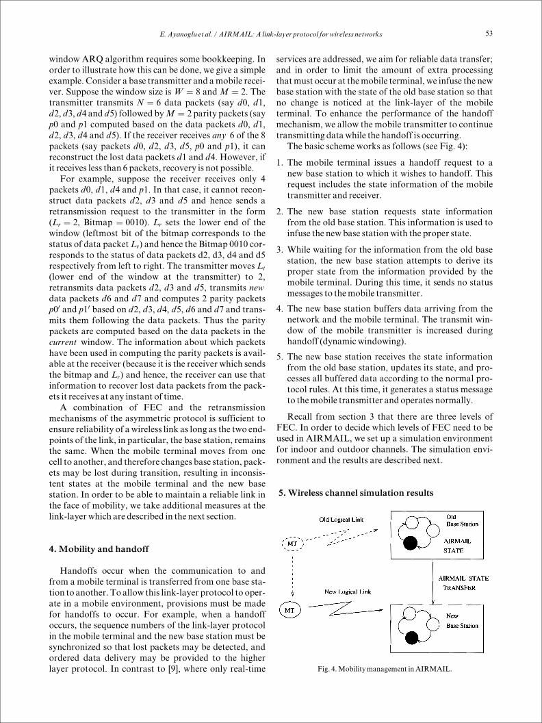
The basic scheme works as follows (see Fig. 4):
1. The mobile terminal issues a handoff request to a
new base station to which it wishes to handoff. This
request includes the state information of the mobile
transmitter and receiver.
2. The new base station requests state information
from the old base station. This information is used to
infuse the new base stationwith the proper state.
3. While waiting for the information from the old base
station, the new base station attempts to derive its
proper state from the information provided by the
mobile terminal. During this time, it sends no status
messages to themobile transmitter.
4. The new base station buffers data arriving from the
network and the mobile terminal. The transmit win-
dow of the mobile transmitter is increased during
handoff (dynamic windowing).
5. The new base station receives the state information
from the old base station, updates its state, and pro-
cesses all buffered data according to the normal pro-
tocol rules. At this time, it generates a status message
to themobile transmitter and operates normally.
Recall from section 3 that there are three levels of
FEC. In order to decide which levels of FEC need to be
used in AIRMAIL, we set up a simulation environment
for indoor and outdoor channels. The simulation envi-
ronment and the results are described next.
5. Wireless channel simulation results
Fig. 4.Mobilitymanagement in AIRMAIL.
E.Ayanoglu et al. / AIRMAIL:A link-layer protocol for wireless networks 53

In this section we will describe the wireless channel
simulations that result in the design decisions of section 3
briefly. With the purpose of studying the characteristics
of indoor and outdoor channels for mobile communica-
tions, a simulation setup was programmed (see Fig. 5). It
is well-known that themobile channel has various effects
that limit the quality of data transmission. The most
important of these is due to multipath fading, i.e., var-
ious natural andman-made objects reflect or scatter car-
riers such that the receiver receives the transmitted
signal over multiple paths. In each such path, there are
random amplitude and phase fluctuations. Further-
more, the mobile causes Doppler shift for each such
path. The combined effect of these events is that themag-
nitude of the received signal becomes Rayleigh distribu-
ted, which can become vanishingly small. The Rayleigh
distribution is the cause of the name Rayleigh fading for
this event. Such channels are closely approximated by
Jake's model [6]. Such a model was programmed and
tested for various indoor and outdoor applications using
differential quadrature phase shift keying for a carrier
frequency of 850MHz, for data rates 64 kb/s and 2Mb/
s, with blocks of size 256 bytes, mobile speeds 5, 35, and
55 mph, and delay spread (RMS delay of various paths)
values of 100 ns (indoor channel) and 3 �s (outdoor
channel). Typical outdoor channel results are shown in
Fig. 6 for a 64 kb/s channel, vehicle speed 35 mph, and
delay spread 3 �s. As can be seen, most blocks have
errored bytes and the number of errored bytes vary sig-
nificantly, but there is a correlation in short term behav-
ior of the number of bytes in error that can be exploited
for changing the bandwidth adaptively. As the number
of errored bytes within a block is usually small, byte-
level forward error correction is the appropriate techni-
que to use. On the other hand, typical indoor channel
results are shown in Fig. 7 for a 2 Mb/s channel, in an
indoor environment when people are walking in the
building (delay spread is 100 ns, speed 5 mph). In this
case the channel is usually error-free, with a large num-
ber of bytes being in error occasionally. When a block
has errors, their number is high so that byte-level for-
ward error correction will not work. On the other hand,
the periodicity of errored blocks indicates packet-level
FEC will work under these circumstances. Results
shown in Figs. 7 and 6 indicate that bit- and byte-level
FEC is appropriate for the narrowband outdoor chan-
nel, while packet-level FEC is appropriate for the wide-
band indoor channel.
The protocol was specified using Communicating
Extended Finite State Machines (CEFSMs), and using
this specification, was translated into textual APSL
(Augmented Protocol Specification Language). Part of
the formal specification of the protocol is given in the
Appendix. The APSL validator was then used to
explore the state space of the protocol in a random
manner. The reason for random exploration is to avoid
the well-known state space explosion. After validation,
the protocol was implemented in several steps. The first
implementation of the asymmetry properties was car-
ried out in the user space with Unix sockets. At this
point, a SunOS 4.1.3 kernel implementation exists as a
loadable kernel module. We made several measure-
ments based on the implementation, which are
described next.
6. Experimental performance results
Fig. 5. Simulation setup. The input to the FEC encoder at the transmit-
ter, b�t�, are bits. The output^
b�t� from the FEC decoder at the receiver
are estimates of b�t�.
Fig. 6. Simulated outdoor channel error characteristics. Number of
bytes in error for each block transmitted is plotted against the block
number. Each block consists of 256 bytes. Transmission rate � 64 kb/
s, vehicle speed� 35mph, delay spread� 3�s.
E.Ayanoglu et al. / AIRMAIL:A link-layer protocol for wireless networks
54

The objective of this section is to justify the claims
we made about the key properties of the protocol,
namely, conserving bandwidth by preventing redundant
retransmissions and conserving power by combining
several status messages into one by the mobile receiver
even in the absence of timers. We also substantiate our
claim of asymmetry by the size of code and the proces-
sing time at the base station and at the mobile terminal.
These results are obtained from the socket-based imple-
mentation of the protocol.
First of all, we show that the protocol minimizes
redundant retransmissions. This conserves the expen-
sive cellular bandwidth. Fig. 8 shows 3 separate plots
corresponding to different packet error rates. The num-
ber of status messages on the horizontal axis is varied
by changing the timeout interval of the status timer at
the base receiver. The plot shows that the number of
packets retransmitted by the mobile transmitter is the
same irrespective of the number of retransmission
requests (the slight variations correspond to different
number of packets lost in different runs), and that num-
ber is exactly equal to the number of lost packets. That
is, if we plot the number of lost packets on the same
axes, it would overlap completely with the plot for num-
ber of retransmitted packets. Thus, even if the base
receiver sends its status messages very frequently, the
mobile transmitter prevents duplicate retransmission.
The same is true for the base transmitter.
The next plot (Fig. 9) shows that there is a trade-off
between sending the status more frequently to obtain a
better response time, versus the wastage of expensive
bandwidth. In this case, the timeout interval of the sta-
tus timer at the base receiver is altered to send status
messages at different frequency to the mobile transmit-
ter. If the status messages are sent too frequently, band-
width is wasted. However, the response time improves.
If the status messages are sent infrequently, bandwidth
is preserved but response time suffers. However, the
good news is that there is an optimal choice of the time-
out interval for the status timer such that the gain in
terms of response time is maximum at the expense of
minimum additional bandwidth. From Fig. 9, the opti-
mal choice is to send 1.5 to 2 status messages per round-
trip delay to the mobile transmitter.
Our measurements indicated that, as expected, the
throughput falls with higher packet error rates. How-
Fig. 7. Simulated indoor channel error characteristics. Number of
bytes in error for each block transmitted is plotted against the block
number. Each block consists of 256 bytes. Transmission rate � 2 Mb/
s, vehicle speed� 5mph, delay spread� 50 ns. Note that the lower fig-
ure is an expanded view of the upper figure.
Fig. 8. No redundant retransmission.
Fig. 9. Trade-off between bandwidth and response time.
E.Ayanoglu et al. / AIRMAIL:A link-layer protocol for wireless networks 55
ever, the normalized throughput of the protocol does
not fall below 0.8 even for a packet error rate of 0.1.
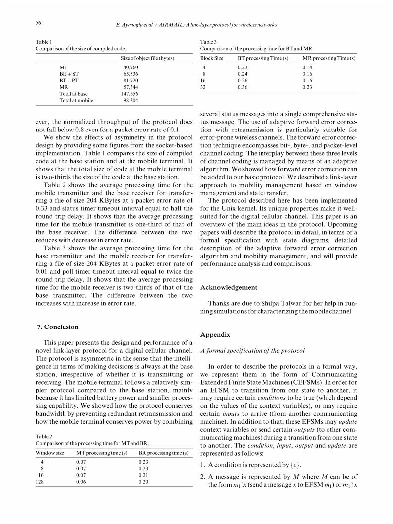
We show the effects of asymmetry in the protocol
design by providing some figures from the socket-based
implementation. Table 1 compares the size of compiled
code at the base station and at the mobile terminal. It
shows that the total size of code at the mobile terminal
is two-thirds the size of the code at the base station.
Table 2 shows the average processing time for the
mobile transmitter and the base receiver for transfer-
ring a file of size 204 KBytes at a packet error rate of
0.33 and status timer timeout interval equal to half the
round trip delay. It shows that the average processing
time for the mobile transmitter is one-third of that of
the base receiver. The difference between the two
reduces with decrease in error rate.
Table 3 shows the average processing time for the
base transmitter and the mobile receiver for transfer-
ring a file of size 204 KBytes at a packet error rate of
0.01 and poll timer timeout interval equal to twice the
round trip delay. It shows that the average processing
time for the mobile receiver is two-thirds of that of the
base transmitter. The difference between the two
increases with increase in error rate.
7. Conclusion
This paper presents the design and performance of a
novel link-layer protocol for a digital cellular channel.
The protocol is asymmetric in the sense that the intelli-
gence in terms of making decisions is always at the base
station, irrespective of whether it is transmitting or
receiving. The mobile terminal follows a relatively sim-
pler protocol compared to the base station, mainly
because it has limited battery power and smaller proces-
sing capability. We showed how the protocol conserves
bandwidth by preventing redundant retransmission and
how the mobile terminal conserves power by combining
several status messages into a single comprehensive sta-
tus message. The use of adaptive forward error correc-
tion with retransmission is particularly suitable for
error-prone wireless channels. The forward error correc-
tion technique encompasses bit-, byte-, and packet-level
channel coding. The interplay between these three levels
of channel coding is managed by means of an adaptive
algorithm.We showed how forward error correction can
be added to our basic protocol.We described a link-layer
approach to mobility management based on window
management and state transfer.
The protocol described here has been implemented
for the Unix kernel. Its unique properties make it well-
suited for the digital cellular channel. This paper is an
overview of the main ideas in the protocol. Upcoming
papers will describe the protocol in detail, in terms of a
formal specification with state diagrams, detailed
description of the adaptive forward error correction
algorithm and mobility management, and will provide
performance analysis and comparisons.
Acknowledgement
Thanks are due to Shilpa Talwar for her help in run-
ning simulations for characterizing themobile channel.
Appendix
A formal specification of the protocol
In order to describe the protocols in a formal way,
we represent them in the form of Communicating
Extended Finite StateMachines (CEFSMs). In order for
an EFSM to transition from one state to another, it
may require certain conditions to be true (which depend
on the values of the context variables), or may require
certain inputs to arrive (from another communicating
machine). In addition to that, these EFSMs may update
context variables or send certain outputs (to other com-
municating machines) during a transition from one state
to another. The condition, input, output and update are
represented as follows:
1. A condition is represented by fcg.
2. A message is represented by M where M can be of
the formm1!x (send amessage x to EFSMm1) orm1?x
Table 1
Comparison of the size of compiled code.
Size of object file (bytes)
MT 40,960
BR� ST 65,536
BT�PT 81,920
MR 57,344
Total at base 147,656
Total at mobile 98,304
Table 2
Comparison of the processing time forMT andBR.
Window size MTprocessing time (s) BR processing time (s)
4 0.07 0.23
8 0.07 0.23
16 0.07 0.21
128 0.06 0.20
Table 3
Comparison of the processing time for BT andMR.
Block Size BTprocessing Time (s) MRprocessing Time (s)
4 0.23 0.14
8 0.24 0.16
16 0.26 0.16
32 0.36 0.23
E.Ayanoglu et al. / AIRMAIL:A link-layer protocol for wireless networks
56
(receive a message x from EFSM m1). The message
x, in general, can have several parameters.
An abbreviation (m1?x�m2?y) will be used to repre-
sent either m1?x or m2?y. Similarly, the abbreviation
(m1!x �m2!y) will be used to represent m1!x followed
bym2!y.
3. An update is represented by [u] where u can be thought
of as a simple program segment which up-dates con-
text variables. The update may depend on conditions.
Thus, u may have conditional statements as well as
assignment statements.
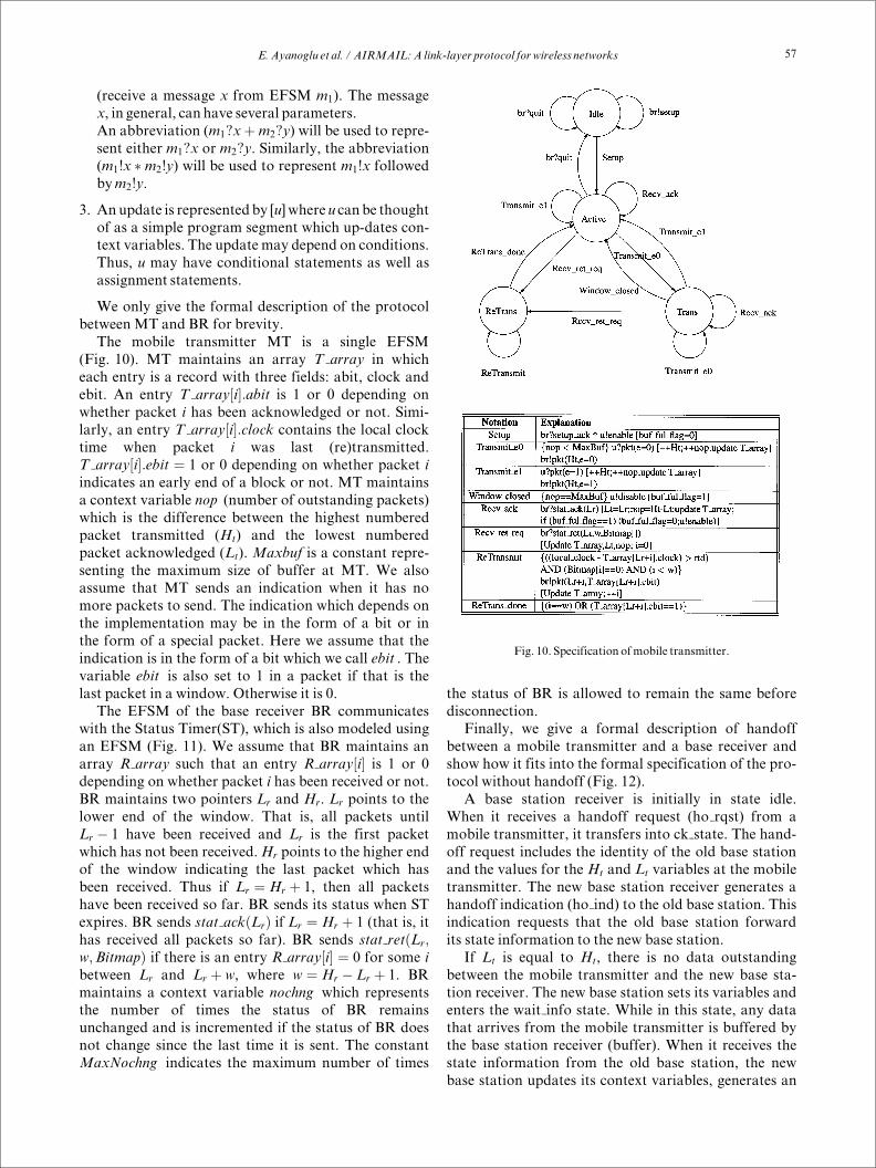
We only give the formal description of the protocol
between MT and BR for brevity.
The mobile transmitter MT is a single EFSM
(Fig. 10). MT maintains an array T array in which
each entry is a record with three fields: abit, clock and
ebit. An entry T array�i�:abit is 1 or 0 depending on
whether packet i has been acknowledged or not. Simi-
larly, an entry T array�i�:clock contains the local clock
time when packet i was last (re)transmitted.
T array�i�:ebit � 1 or 0 depending on whether packet i
indicates an early end of a block or not. MT maintains
a context variable nop (number of outstanding packets)
which is the difference between the highest numbered
packet transmitted (Ht
) and the lowest numbered
packet acknowledged (Lt
). Maxbuf is a constant repre-
senting the maximum size of buffer at MT. We also
assume that MT sends an indication when it has no
more packets to send. The indication which depends on
the implementation may be in the form of a bit or in
the form of a special packet. Here we assume that the
indication is in the form of a bit which we call ebit . The
variable ebit is also set to 1 in a packet if that is the
last packet in a window. Otherwise it is 0.
The EFSM of the base receiver BR communicates
with the Status Timer(ST), which is also modeled using
an EFSM (Fig. 11). We assume that BR maintains an
array R array such that an entry R array�i� is 1 or 0
depending on whether packet i has been received or not.
BR maintains two pointers Lr
and H
r
. Lr
points to the
lower end of the window. That is, all packets until
L
r
ÿ 1 have been received and L
r
is the first packet
which has not been received.Hr
points to the higher end
of the window indicating the last packet which has
been received. Thus if L
r
� H
r
� 1, then all packets
have been received so far. BR sends its status when ST
expires. BR sends stat ack�Lr
� if Lr
� H
r
� 1 (that is, it
has received all packets so far). BR sends stat ret�Lr
;
w;Bitmap� if there is an entry R array�i� � 0 for some i
between L
r
and L
r
� w, where w � H
r
ÿ L
r
� 1. BR
maintains a context variable nochng which represents
the number of times the status of BR remains
unchanged and is incremented if the status of BR does
not change since the last time it is sent. The constant
MaxNochng indicates the maximum number of times
the status of BR is allowed to remain the same before
disconnection.
Finally, we give a formal description of handoff
between a mobile transmitter and a base receiver and
show how it fits into the formal specification of the pro-
tocol without handoff (Fig. 12).
A base station receiver is initially in state idle.
When it receives a handoff request (ho rqst) from a
mobile transmitter, it transfers into ck state. The hand-
off request includes the identity of the old base station
and the values for the Ht
and L
t
variables at the mobile
transmitter. The new base station receiver generates a
handoff indication (ho ind) to the old base station. This
indication requests that the old base station forward
its state information to the new base station.
If L
t
is equal to H
t
, there is no data outstanding
between the mobile transmitter and the new base sta-
tion receiver. The new base station sets its variables and
enters the wait info state. While in this state, any data
that arrives from the mobile transmitter is buffered by
the base station receiver (buffer). When it receives the
state information from the old base station, the new
base station updates its context variables, generates an
Fig. 10. Specification ofmobile transmitter.
E.Ayanoglu et al. / AIRMAIL:A link-layer protocol for wireless networks
57

acknowledgment to the old base station, generates a
status message to the mobile transmitter, and moves to
the Active state. In the Active state, the base station
receiver processes all of the data buffered during the
handoff process, and any new data that arrives, accord-
ing to the normal protocol rules.
If Ltis less than H
t, data is outstanding between the
new base station receiver and mobile transmitter and
the base station receiver enters state wait missing. In
this state, the new base station receiver buffers any data
it receives (buffer missing) until it receives the state
information from the old base station. At this time, it
processes the R array received from the old base sta-
tion. The new base station requests (get data(i)) that
the old base station forward it any data (data(i)) that it
has received and buffered. When this has been com-
pleted, the new base station contains all data that has
been previously transmitted by the mobile terminal that
has been either not forwarded to the higher layer proto-
col by the old base station or lost in transmission. The
new base station receiver generates an acknowledgment
to the old base station, a status message to the mobile
transmitter, and transitions into Active state. While in
the Active state, the new base station processes any buf-
fered data and newly arriving data according to the nor-
mal protocol rules.
When a base station in Active state receives a hand-
off indication from a new base station, it sends the new
base station its state information. If the old base
station receives any requests for data it has buffered
(get data(i)), it sends this data to the new base station
(data(i)). When the old base station receives an
acknowledgment from the new base station it clears its
record and enters the idle state.
During a handoff, it is possible that the window
of the mobile transmitter will close. This is because the
new base station does not generate any status messages
until it has completely synchronized its state. To solve
this problem we use a technique called dynamic win-
dowing.
When the mobile transmitter requests a handoff, it
increases its window size temporarily. This allows it to
continue transmitting past its normal window size. The
transmit window is reduced to its proper size when the
status message is received from the new base station.
References
[1] E. Ayanoglu, C.-L. I, R.D. Gitlin and J. E. Mazo, Diversity
coding for self-healing and fault-tolerant communication
Networks, IEEE Trans. Commun. COM-41 (1993) 1677^1686.
[2] Cellular Digital Packet Data System Specification Release 1.0,
Book III (CDPD Industry Input Coordinator, Costa Mesa, CA,
July 1993).
Fig. 11. Specification of base receiver.
Fig. 12. Specification of base receiver during handoff.
E.Ayanoglu et al. / AIRMAIL:A link-layer protocol for wireless networks
58

[3] R. Caceres and L. Iftode, The effects of mobility on reliable
transport protocols, Proc. 14th ICDCS, June 1994.
[4] D.D. Clark, M.L. Lambert and L. Zhang, NETBLT: A bulk
data transfer protocol, Proc. ACM SIGCOMM '87 Symp.
Stowe, Vermont, August 1987, pp. 353^359.
[5] A. DeSimone, M.C. Chuah and O.C. Yue, Throughput per-
formance of transport layer protocols over wireless LANs, Proc.
IEEE GLOBECOM '93, Houston, November 1993, pp. 542^
549.
[6] W.C. Jakes (ed.), Microwave Mobile Communications (Wiley,
1974; Reissued by IEEE Press, 1994).
[7] P. Karn, The Qualcomm CDMA digital cellular system,
USENIX Mobile and Location-Independent Symp. Proc.,
Cambridge, Massachusetts, August 1993, pp. 35^40.
[8] R.E. Kahn, S.A. Gronemeyer, J. Burchfiel and
R.C. Kunzelman, Advances in packet radio technology, Proc.
IEEE 66 (1978) 1468^1496.
[9] K. Keeton, B.A. Mah, S. Seshan, R.H. Katz and D. Ferrari,
Providing connection-oriented network services to mobile hosts,
USENIX Mobile and Location-Independent Symp. Proc.,
Cambridge, Massachusetts, August 1993, pp. 83^102.
[10] S. Lin and D.J. Costello, Error Control Coding: Fundamentals
and Applications (Prentice-Hall, Englewood-Cliffs, NJ, 1983).
[11] B.M. Leiner, D.L. Nielson and F.A. Tobagi, Issues in packet
radio design, Proc. IEEE 75 (1987) 6^20.
[12] S. Nanda, R. Ejzak and B.T. Doshi, A retransmission scheme
for circuit-mode data on wireless links, accepted for publication
in IEEE J. Select. Areas Commun.
[13] A.N. Netravali, W.D. Roome and K.K. Sabnani, Design and
implementation of a high speed transport protocol, IEEE Trans.
Commun. COM-38 (1990) 721^730.
[14] W. Simpson, IP mobility support, Submission to Internet
Engineering Task Force (1994).
Ender Ayanoglu was born in Turkey on
November 26, 1958. He received the B.S.
degree from the Middle East Technical Uni-
versity, Turkey, in 1980, and the M.S. and
Ph.D. degrees from Stanford University,
California, in 1982 and 1986, respectively, all
in electrical engineering. Since 1986, he has
been with AT & T Bell Laboratories where he
is currently a Member of Technical Staff in
the Communication Systems Research
Laboratory. He taught at Stanford University during Spring 1985,
and at Bilkent University, Turkey, during the academic year 1990^
1991, and during Fall 1992. He has published numerous conference
and journal papers, holds several patents, and has been on the pro-
gram committees of several IEEE conferences. His research interests
include communication theory, signal processing, information theory,
and communication networks, in particular, source coding, joint
source and channel coding, basic communication theory, error and
loss control, and restoration, for various communications and net-
working applications, including B-ISDN/ATM networks and wireless
networks. He is an Editor of the IEEE Transactions on Communica-
tions for Communication Theory and Coding Applications, and the
Secretary of the Communication Theory Technical Committee of the
IEEE Communications Society.
Sanjoy Paul (ACM S'89, ACM'92, Member
IEEE'92) obtained his B. Tech (Hons.) from
the Indian Institute of Technology, Kharag-
pur, in electronics and electrical communica-
tions engineering (EECE) in 1985, followed
by M.S and Ph.D in electrical engineering
from the University of Maryland, College
Park, in 1988 and 1992, respectively. He
worked as an Assistant Systems Engineer in
India for CMC Limited during 1985-1986. He
joined the Distributed Systems Research Department at AT & T Bell
Laboratories, Murray Hill, in 1992. Currently, he is with the Wireless
Networking Research Department at Bell Laboratories, Holmdel.
His technical interests include design, analysis, validation, verifica-
tion, conformance testing and performance evaluation of communica-
tion protocols; security and privacy; and wireless networking.
Thomas F. La Porta received his B.S.E.E.
and M.S.E.E. degrees from The Cooper
Union, New York, NY, in 1986 and 1987,
respectively, and his Ph.D. degree in electrical
engineering from Columbia University, New
York, NY, in 1992. He joined AT & T Bell
Laboratories in 1986. He is currently a Mem-
ber of Technical Staff in the Wireless Net-
working Research Department. His research
interests include signaling and control for
broadband and wireless networks and mobility management. Dr. La
Porta is a Technical Editor for the IEEE Personal Communications
Magazine.
Krishan K. Sabnani received a B. Tech.
degree from the Indian Institute of Technol-
ogy, New Delhi, India, and a Ph. D. degree
from Columbia University, New York, NY.
In 1981, he joined AT & T Bell Laboratories
after graduating from Columbia University.
He is currently a research department head
in AT & T Bell Laboratories. His major area
of interest is communication protocols.
Krishan received the Leonard G. Abraham
award from the IEEE Communications Society in 1991. He received
the Bell Laboratories Distinguished Technical Staff award in 1990.
He is also a Fellow of the IEEE. He also received the President of
India's Gold Medal and the Institute of Engineers (India) Gold
Medal, both in 1975. Krishan has served as an editor for several jour-
nals including IEEE Transactions on Communications and IEEE
Transactions on Computers.
Richard D. Gitlin was born in Brooklyn,
N.Y., on April 25, 1943. He received the
D.Eng.Sc. degree from Columbia University,
New York, N.Y., in 1969. Since 1969, he has
been with AT & T Bell Laboratories, Holm-
del, N.J., where he is Director of the Commu-
nications Systems Research Laboratory. In
this position he is responsible for research in
wireless systems, broadband networking, and
local access and switching systems. From
1969 to 1979, he did applied research and exploratory development in
the field of high-speed voiceband modems, from 1979 to 1982 he
supervised a group doing exploratory and advanced development in
these areas and from 1982 to 1987 he was Head of a department
responsible for systems engineering, exploratory development, and
final development of data communications equipment. He was
responsible for leading the pioneering efforts that led to the V.32 pro-
E.Ayanoglu et al. / AIRMAIL:A link-layer protocol for wireless networks59
duct family and to the HDSL technology. From 1987 until 1992, he
was Head of the Network Systems Research Department where he
managed research in broadband networking, including: Gigabit/sec
packet switches and LANs, high-speed protocols, broadband applica-
tions, and the LuckyNet gigabit research network. Dr. Gitlin is the
author of more than 70 technical papers and numerous conference
papers, and he holds 35 patents in the areas of data communications,
digital signal processing, and broadband networking. He is a co-
author of the text, Data Communication Principles (Plenum Press,
1992). He is co-author of a paper on fractionally spaced adaptive
equalization that was selected as the Best Paper in Communications
by the Bell System Technical Journal in 1982, and a co-author of the
paper, Reducing the Effects of Transmission Impairments in Digital
Fiber-Optic Systems, published in the IEEE Communications Maga-
zine in 1993 that received the IEEE Communications Society's Fred
W. Ellersick Prize Paper Award. He has served as Chairman of the
Communication Theory Committee of the IEEE Communications
Society, as a member of the COMSOC Awards Board, Editor for
Communication Theory of the IEEE Transactions on Communica-
tions, and a member of the Editorial Advisory Board of the Proceed-
ings of the IEEE. Currently, he is a member of the Board of
Governors of the IEEE Communications Society and a member of the
Nominations and Elections Board. In 1985 he was elected a Fellow
of the IEEE for his contributions to data communications technology,
and in 1987 he was named an AT & T Bell Laboratories Fellow.
E.Ayanoglu et al. / AIRMAIL:A link-layer protocol for wireless networks
60


![Link Layer Protocol€¦ · Link Layer Protocol ... tional concepts taken from the HDLC protocol defined in [4]. ... These interfaces are explained in the following sections.](https://static.fdocuments.us/doc/165x107/5b089f2b7f8b9a93738cac52/link-layer-layer-protocol-tional-concepts-taken-from-the-hdlc-protocol-defined.jpg)