
AIRLIFT BIOREACTORS - Ferdowsi University of...
28
4/7/2012 1 AIRLIFT BIOREACTORS contents Introduction Fluid Dynamics Mass Transfer Airlift Reactor—Selection and Design
Transcript of AIRLIFT BIOREACTORS - Ferdowsi University of...

4/7/2012
1
AIRLIFT BIOREACTORS
contents
Introduction Fluid Dynamics Mass Transfer Airlift Reactor—Selection and Design

4/7/2012
2
INTRODUCTION
• airlift reactor (ALR) covers a wide range of gas–liquid or gas–liquid–solid pneumatic contacting devices that are characterized by fluid circulation in a defined cyclic pattern
• Role of gas stream
• Difference between ALRs and bubble columns
Airlift reactors on the basis of their structure
• 1) external loop vessels
• 2) baffled (or internal-loop) vessels
4/7/2012
3
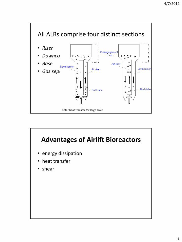
All ALRs comprise four distinct sections
• Riser
• Downcomer
• Base
• Gas separator
Beter heat transfer for large scale
Advantages of Airlift Bioreactors
• energy dissipation
• heat transfer
• shear

4/7/2012
4
Gas injected to the Airlift reactors
where ∆Pb is the pressure difference, is the density of the liquid (the density of the gas is considered to be negligible),g is the gravitational constant, and and are the fractional gas holdup of the riser and downcomer
the difference in gas holdup between the riser and the downcomer
efficiency of ALRs
Aeration efficiency as a function of pneumatic power of gas input per unit volume in a straightbaffleALR

4/7/2012
5
• Energy economy
• The advantages counterbalance the obvious disadvantage of ALRs
FLUID DYNAMICS
• Design variables : reactor
height, riser-to-downcomer area ratio, geometrical design of gas separator, and the bottom clearance
• Operating variables : gas
input rate , top clearance
liquid velocity in the ALR
4/7/2012
6
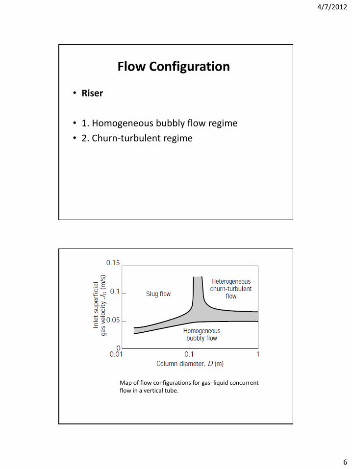
Flow Configuration
• Riser
• 1. Homogeneous bubbly flow regime
• 2. Churn-turbulent regime
Map of flow configurations for gas–liquid concurrent flow in a vertical tube.

4/7/2012
7
• Downcomer.
•cross-sectional area ratio of the riser to the downcomer
• Gas Separator.
• Gas Holdup
(2)
where the subindexes L, G, and S indicate liquid, gas, and solid, and i indicates the region in which the holdup is considered

4/7/2012
8
Importance of the holdup
• 1) the value of the holdup gives an indication of the potential for mass transfer
• 2) the difference in holdup between the riser and the downcomer generates the driving force for liquid circulation
Gas Holdup in Internal Airlift Reactors.
(3)
JG is the superficial gas velocity, is the effective viscosity of the liquid,and and a are constants

4/7/2012
9
(4)
Qin is the freshly injected gas, Qd is the recirculated gas
Some correlations proposed for prediction of gas holdup in the riser of internal-loop ALRs.

4/7/2012
10
External-Loop Airlift Reactors.
• By using Drift flux model
• Drift velocities of the gas and liquid phases
where A is cross-sectional area, C0 is distribution parameter, J is superficial velocity, JG is superficial gas velocity, UG linear gas velocity, and ϕ is gas holdup
4/7/2012
11
• The value of C0 depends mainly on the radial profile of the gas holdup
• C0 = 1 for a flat profile and C0 = 1.5 for a parabolic profile
• C0 = 1.03–1.2 for upflow,
• C0 = 1.0–1.16 for downflow
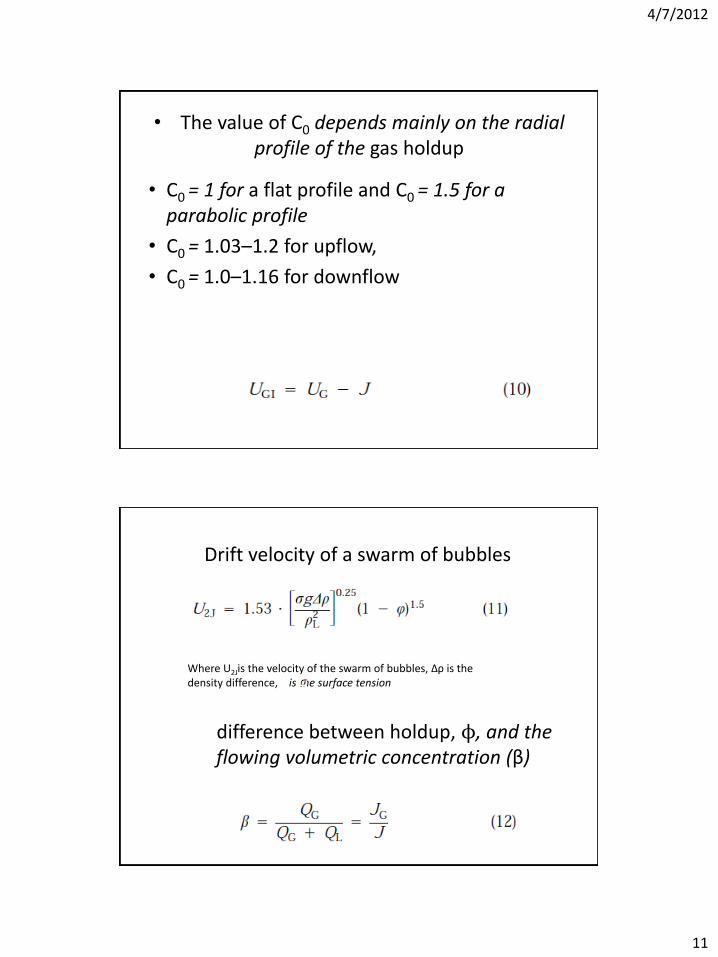
Drift velocity of a swarm of bubbles
Where U2Jis the velocity of the swarm of bubbles, ∆ρ is the density difference, is the surface tension
difference between holdup, ϕ, and the flowing volumetric concentration (β)

4/7/2012
12
connection between the gas holdup and β
J is the superficial velocity, is the terminal gas velocity
For riser
For downcomer
Gas flow holdup (ϕ) vs. flowing volumetric concentration (β). The different zones in the plane ϕ-β identify the two phase flow.

4/7/2012
13
Dependence of the riser gas holdup in a 4-m high external-loop ALR with a multiple-orifice sparger (solid lines) and a single-orifice sparger (broken lines).
holdup increases with height.
gas holdup in the riser
where the constant α depends on the friction losses in the loop, and β is usually a value between 0.6 and 0.7
Gas holdup reported by various sources for the riser of airlift reactors under conditions of little or no gas recirculation.The data correspond to different Ad/Ar ratios.
4/7/2012
14
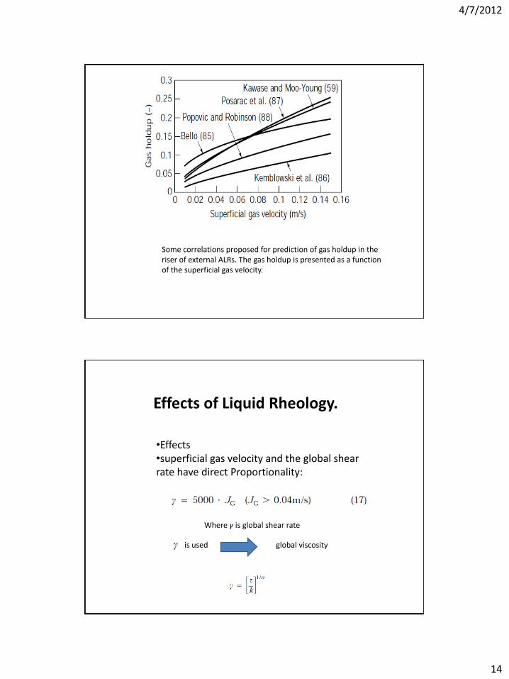
Some correlations proposed for prediction of gas holdup in the riser of external ALRs. The gas holdup is presented as a function of the superficial gas velocity.
Effects of Liquid Rheology.
•Effects •superficial gas velocity and the global shear rate have direct Proportionality:
Where γ is global shear rate
is used global viscosity

4/7/2012
15
LR is an effective length that represents the mean circulation path of a bubble in the system considered, P is the power input, Sab is the total surface of all of bubbles, and τ is the shear stress
where the subindexes 1 and 2 represent the two extremes of the section considered
Effect of Liquid Level.
Riser and downcomer gas holdup in an internal-loop ALR for two different top clearances and two liquids

4/7/2012
16
Gas holdup in the riser of an external-loop ALR for several top clearances
?
Gas Recirculation
Gas recirculation in a split-cylinder ALR. The level indicated corresponds to no-aeration conditions.

4/7/2012
17
The mathematical expression that gives this maximal gas recirculation is:
(20)
where Qd is the gas flow rate in the downcomer, QL is the liquid circulation flow rate, Pi is pressure at point i of the reactor (1 is top of the riser, 2 is top of the downcomer, 3 is bottom of the downcomer, 4 is bottom of the riser), Cd is the hydraulic resistance coefficient, UL is the linear liquid velocity
Liquid Velocity
• affects the gas holdup in the riser and downcomer, the mixing time, the mean residence time of the gas phase, the interfacial area, and the mass and heat transfer coefficients.

4/7/2012
18
Modeling of Liquid Flow.
• Two main methods for the modeling of two-phase flow in ALRs
• energy balances and momentum balances
• expression for the average superficial liquid velocity based on energy balance:
where Kb,Kt are the hydraulic pressure loss coefficients
Authors assume that Kt , the friction coefficient at the top of the loop, is negligible in concentric-tube type reactors and that in external-loop reactors Kt can be taken as equal to Kb ,the friction coefficient for the bottom of the loop.
empirical correlation for Kb
where Ab is the minimal cross section at the bottom of the airlift reactor.

4/7/2012
19
the riser-to-downcomer cross-sectional area ratio and the reactor height are the main parameters that affect the superficial liquid velocity at constant superficial gas velocity.
Liquid velocity predicted by some of the proposed correlations
Liquid Mixing
• tm
• degree of homogeneity (I):
where C is the maximum local concentration and Cm is the mean concentration of tracer at complete mixing.

4/7/2012
20
• Study of the residence time distribution (RTD)
• The axial dispersion model
where C is the concentration of a tracer
Bodenstein number (Bo), which is used to describe the mixing in the reactor:
where L is the characteristic length
Bo the mixing conditions are similar to those
of a plug-flow reactor
Low Bo no. the reactor can be considered as well-mixed
where M is a constant equal to 0.093 or to 0.089
for Bo 50 and a degree of inhomogeneity,I = 0.05

4/7/2012
21
where Dz is the dispersion coefficient and D is the column diameter
where JL is the superficial liquid velocity and Uc is the cell circulation velocity given by:
Where is the terminal bubble velocity
Mixing in the Gas Phase
Energy Dissipation and Shear Rate in Airlift Reactors
Extended to mass transfer proposed the expression:

4/7/2012
22
The general energy balance
Downcomer
Bottom
Riser
Gas separator
Schematic description of the variables in the thermodynamic model for energy dissipation distribution in an ALR.

4/7/2012
23
The shear stress in the liquid of each region of the reactor can be defined as the energy dissipated divided by the mean path of circulation in the region and by the sum of the areas of all the bubbles
For the region i in the ALR
where ti is the residence time of the liquid, hi is the effective length, and ai is the specific interfacial area, in the region i.
A global shear rate ci can be calculated for each region i as
MASS TRANSFER
• 1) static properties of the liquid
• 2) dynamic properties of the liquid
• 3) liquid dynamics.
Mass Transfer Rate Measurements:
• steady-state and nonsteady-state methods
valid only for perfectly mixed systems

4/7/2012
24
Bubble Size and Interfacial Area
• in a population of homogeneous bubble size
where the Sauter mean diameter (dS) is given by
Influence of the superficial gas velocity on overall kLa and on the kLa in each of the regions of an ALR.

4/7/2012
25
for the volumetric mean diameter of the bubbles in the riser of a concentric-tube ALR
where dO is the diameter of the sparger orifice
and the function f (NW ) is different for each range of NW
Data Correlations for Mass Transfer Rate
• Hydrodynamic • thermodynamic
Influence of the superficial gas velocity on overall kLa and on the kLa in each of the regions of an ALR

4/7/2012
26
AIRLIFT REACTOR—SELECTION AND DESIGN
Scale-up of Airlift Bioreactors
• purposes
• problems
Results for a scaled-up bioreactor with a constant oxygen transfer rate

4/7/2012
27
Schematic representation of the scale-down method
relationship between total circulation time and residence time in the downcomer
Influence of residence time in the poorly aerated downcomer on the production of A. pullulans.

4/7/2012
28
Design Improvements


![Airlift Bioreactors: Hydrodynamics and Rheology …cdn.intechopen.com/pdfs/45352/InTech-Airlift_bioreactors...diameter of the reactor, as can be seen in Figure 5 [12]. The slug-flow](https://static.fdocuments.us/doc/165x107/5ce0d11788c99349468df1ec/airlift-bioreactors-hydrodynamics-and-rheology-cdn-of-the-reactor-as-can-be-seen.jpg)