Aircrew Survival Equipmentman 1 & C -...
167
DISTRIBUTION STATEMENT A: Approved for public release; distribution is unlimited. NONRESIDENT TRAINING COURSE December 1985 Aircrew Survival Equipmentman 1 & C NAVEDTRA 14217
Transcript of Aircrew Survival Equipmentman 1 & C -...
DISTRIBUTION STATEMENT A: Approved for public release; distribution is unlimited.
NONRESIDENTTRAININGCOURSE
December 1985
Aircrew SurvivalEquipmentman 1 & CNAVEDTRA 14217

DISTRIBUTION STATEMENT A: Approved for public release; distribution is unlimited.
Although the words “he,” “him,” and“his” are used sparingly in this course toenhance communication, they are notintended to be gender driven or to affront ordiscriminate against anyone.

i
PREFACE
By enrolling in this self-study course, you have demonstrated a desire to improve yourself and the Navy.Remember, however, this self-study course is only one part of the total Navy training program. Practicalexperience, schools, selected reading, and your desire to succeed are also necessary to successfully roundout a fully meaningful training program.
THE COURSE: This self-study course is organized into subject matter areas, each containing learningobjectives to help you determine what you should learn along with text and illustrations to help youunderstand the information. The subject matter reflects day-to-day requirements and experiences ofpersonnel in the rating or skill area. It also reflects guidance provided by Enlisted Community Managers(ECMs) and other senior personnel, technical references, instructions, etc., and either the occupational ornaval standards, which are listed in the Manual of Navy Enlisted Manpower Personnel Classificationsand Occupational Standards, NAVPERS 18068.
THE QUESTIONS: The questions that appear in this course are designed to help you understand thematerial in the text.
VALUE: In completing this course, you will improve your military and professional knowledge.Importantly, it can also help you study for the Navy-wide advancement in rate examination. If you arestudying and discover a reference in the text to another publication for further information, look it up.
1985 Edition Prepared byPRC Vernon L. Rising and PRCM Paul Quinlan, Ret.
Published byNAVAL EDUCATION AND TRAINING
PROFESSIONAL DEVELOPMENTAND TECHNOLOGY CENTER
NAVSUP Logistics Tracking Number0504-LP-022-3670

ii
Sailor’s Creed
“ I am a United States Sailor.
I will support and defend theConstitution of the United States ofAmerica and I will obey the ordersof those appointed over me.
I represent the fighting spirit of theNavy and those who have gonebefore me to defend freedom anddemocracy around the world.
I proudly serve my country’s Navycombat team with honor, courageand commitment.
I am committed to excellence andthe fair treatment of all.”
CONTENTS
CHAPTER Page
1. Liquid Oxygen Converter Test Stand 59A120 . . . . . . . . . . . . . . . 1-1
2. Oxygen Component Test Stand (1172AS100) . . . . . . . . . . . . . . . 2-1
3. Carbon Dioxide Transfer Equipment . . . . . . . . . . . . . . . . . . . . . . 3-1
4. Sewing Machine Repair . . . . . . . . . . . . . . . . . . . . . . . . . . . . . . . . . . 4-1
5. Aircrew Survival Equipment Training . . . . . . . . . . . . . . . . . . . . . 5-1
INDEX . . . . . . . . . . . . . . . . . . . . . . . . . . . . . . . . . . . . . . . . . . . . I-1
iii
AIRCREW SURVIVALEQUIPMENTMAN 1 & C
OCCUPATIONAL STANDARDS
N U M B E R O C C U P A T I O N A L S T A N D A R D C H A P T E R
18 TEST EQUIPMENT
18112 PREPARE CALIBRATION AND FLOW CHARTS FOR TESTING 1, 2OXYGEN SYSTEMS COMPONENTS
18113 M A I N T A I N A N D R E P A I R O X Y G E N S Y S T E M S C O M P O N E N T S 1, 2TEST STAND AND LIQUID OXYGEN CONVERTER TEST STAND
44 TRAINING
44011 SUPERVISE AIRCREW SURVIVAL EQUIPMENT TRAINING 5
94 MECHANICAL MAINTENANCE
94042 TROUBLESHOOT SEWING MACHINE MALFUNCTIONS; REPAIR 4AND REPLACE PARTS
99 AIRCREW SURVIVAL EQUIPMENT
99017 MAINTAIN CARBON DIOXIDE RECHARGE EQUIPMENT 3
99027 REPAIR OXYGEN BREATHING REGULATORS 2
99028 R E P A I R E M E R G E N C Y O X Y G E N S Y S T E M S , A N D E N V I R O N - 1M E N T A L A N D C O M M U N I C A T I O N S C O M P O N E N T S I N S E A TCONTAINED SURVIVAL KITS
99029 REPAIR LIQUID OXYGEN CONVERTERS AND COMPONENTS 1
iv
v
INSTRUCTIONS FOR TAKING THE COURSE
ASSIGNMENTS
The text pages that you are to study are listed atthe beginning of each assignment. Study thesepages carefully before attempting to answer thequestions. Pay close attention to tables andillustrations and read the learning objectives.The learning objectives state what you should beable to do after studying the material. Answeringthe questions correctly helps you accomplish theobjectives.
SELECTING YOUR ANSWERS
Read each question carefully, then select theBEST answer. You may refer freely to the text.The answers must be the result of your ownwork and decisions. You are prohibited fromreferring to or copying the answers of others andfrom giving answers to anyone else taking thecourse.
SUBMITTING YOUR ASSIGNMENTS
To have your assignments graded, you must beenrolled in the course with the NonresidentTraining Course Administration Branch at theNaval Education and Training ProfessionalDevelopment and Technology Center(NETPDTC). Following enrollment, there aretwo ways of having your assignments graded:(1) use the Internet to submit your assignmentsas you complete them, or (2) send all theassignments at one time by mail to NETPDTC.
Grading on the Internet: Advantages toInternet grading are:
• you may submit your answers as soon asyou complete an assignment, and
• you get your results faster; usually by thenext working day (approximately 24 hours).
In addition to receiving grade results for eachassignment, you will receive course completionconfirmation once you have completed all the
assignments. To submit your assignmentanswers via the Internet, go to:
http://courses.cnet.navy.mil
Grading by Mail: When you submit answersheets by mail, send all of your assignments atone time. Do NOT submit individual answersheets for grading. Mail all of your assignmentsin an envelope, which you either provideyourself or obtain from your nearest EducationalServices Officer (ESO). Submit answer sheetsto:
COMMANDING OFFICERNETPDTC N3316490 SAUFLEY FIELD ROADPENSACOLA FL 32559-5000
Answer Sheets: All courses include one“scannable” answer sheet for each assignment.These answer sheets are preprinted with yourSSN, name, assignment number, and coursenumber. Explanations for completing the answersheets are on the answer sheet.
Do not use answer sheet reproductions: Useonly the original answer sheets that weprovide—reproductions will not work with ourscanning equipment and cannot be processed.
Follow the instructions for marking youranswers on the answer sheet. Be sure that blocks1, 2, and 3 are filled in correctly. Thisinformation is necessary for your course to beproperly processed and for you to receive creditfor your work.
COMPLETION TIME
Courses must be completed within 12 monthsfrom the date of enrollment. This includes timerequired to resubmit failed assignments.
vi
PASS/FAIL ASSIGNMENT PROCEDURES
If your overall course score is 3.2 or higher, youwill pass the course and will not be required toresubmit assignments. Once your assignmentshave been graded you will receive coursecompletion confirmation.
If you receive less than a 3.2 on any assignmentand your overall course score is below 3.2, youwill be given the opportunity to resubmit failedassignments. You may resubmit failedassignments only once. Internet students willreceive notification when they have failed anassignment--they may then resubmit failedassignments on the web site. Internet studentsmay view and print results for failedassignments from the web site. Students whosubmit by mail will receive a failing result letterand a new answer sheet for resubmission of eachfailed assignment.
COMPLETION CONFIRMATION
After successfully completing this course, youwill receive a letter of completion.
ERRATA
Errata are used to correct minor errors or deleteobsolete information in a course. Errata mayalso be used to provide instructions to thestudent. If a course has an errata, it will beincluded as the first page(s) after the front cover.Errata for all courses can be accessed andviewed/downloaded at:
http:/ /www.advancement.cnet.navy.mi l
STUDENT FEEDBACK QUESTIONS
We value your suggestions, questions, andcriticisms on our courses. If you would like tocommunicate with us regarding this course, weencourage you, if possible, to use e-mail. If youwrite or fax, please use a copy of the StudentComment form that follows this page.
For subject matter questions:
E-mail: [email protected]: Comm: (850) 452-1777
DSN: 922-1777FAX: (850) 452-1370(Do not fax answer sheets.)
Address: COMMANDING OFFICERNETPDTC (CODE N315)6490 SAUFLEY FIELD ROADPENSACOLA FL 32509-5237
For enrollment, shipping, grading, orcompletion letter questions
E-mail: [email protected]: Comm: (850) 452-1511/1181/1859
DSN: 922-1511/1181/1859FAX: (850) 452-1370(Do not fax answer sheets.)
Address: COMMANDING OFFICERNETPDTC (CODE N331)6490 SAUFLEY FIELD ROADPENSACOLA FL 32559-5000
NAVAL RESERVE RETIREMENT CREDIT
If you are a member of the Naval Reserve, youwill receive retirement points if you areauthorized to receive them under currentdirectives governing retirement of NavalReserve personnel. For Naval Reserveretirement, this course is evaluated at 8 points.(Refer to Administrative Procedures for NavalReservists on Inactive Duty, BUPERSINST1001.39, for more information about retirementpoints.)
COURSE OBJECTIVES
In completing this nonresident training course,you will demonstrate a knowledge of the subjectmatter by correctly answering questions on thefollowing: oxygen test; stands, carbon dioxidetransfer equipment, sewing machine repair andsurvival equipment training.
vii
Student Comments
Course Title: Aircrew Survival Equipmentman 1 & C
NAVEDTRA: 140217 Date:
We need some information about you:
Rate/Rank and Name: SSN: Command/Unit
Street Address: City: State/FPO: Zip
Your comments, suggestions, etc.:
Privacy Act Statement: Under authority of Title 5, USC 301, information regarding your military status isrequested in processing your comments and in preparing a reply. This information will not be divulged withoutwritten authorization to anyone other than those within DOD for official use in determining performance.
NETPDTC 1550/41 (Rev 4-00)

CHAPTER 1
LIQUID OXYGEN CONVERTERTEST STAND 59A120
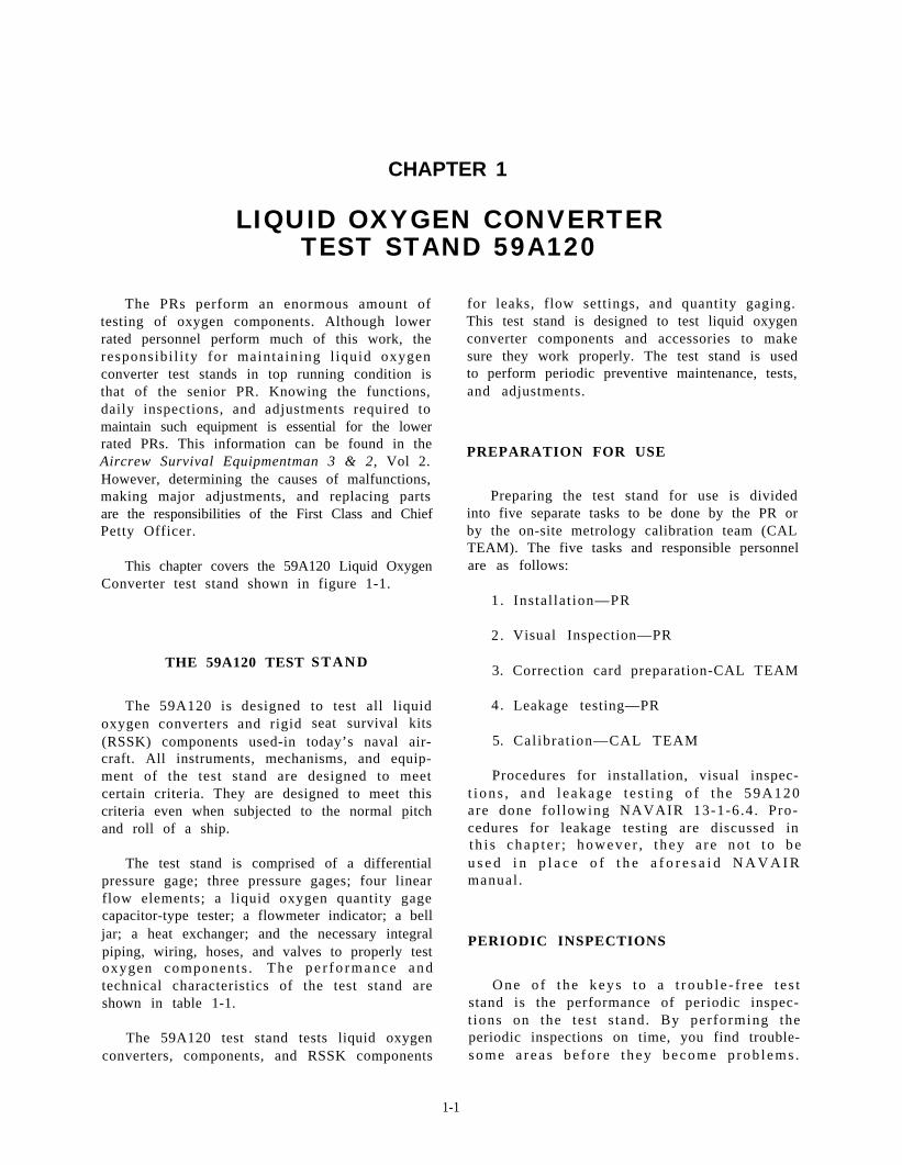
The PRs perform an enormous amount oftesting of oxygen components. Although lowerrated personnel perform much of this work, theresponsibi l i ty for maintaining l iquid oxygenconverter test stands in top running condition isthat of the senior PR. Knowing the functions,daily inspections, and adjustments required tomaintain such equipment is essential for the lowerrated PRs. This information can be found in theAircrew Survival Equipmentman 3 & 2, Vol 2.However, determining the causes of malfunctions,making major adjustments, and replacing partsare the responsibilities of the First Class and ChiefPetty Officer.
This chapter covers the 59A120 Liquid OxygenConverter test stand shown in figure 1-1.
THE 59A120 TEST
The 59A120 is designedoxygen converters and rigid
S T A N D
to test all liquidseat survival kits
(RSSK) components used-in today’s naval air-craft. All instruments, mechanisms, and equip-ment of the test stand are designed to meetcertain criteria. They are designed to meet thiscriteria even when subjected to the normal pitch.and roll of a ship.
The test stand is comprised of a differentialpressure gage; three pressure gages; four linearflow elements; a liquid oxygen quantity gagecapacitor-type tester; a flowmeter indicator; a belljar; a heat exchanger; and the necessary integralpiping, wiring, hoses, and valves to properly testoxygen components . T h e p e r f o r m a n c e a n dtechnical characteristics of the test stand areshown in table 1-1.
The 59A120 test stand tests liquid oxygenconverters, components, and RSSK components
for leaks, flow settings, and quantity gaging.This test stand is designed to test liquid oxygenconverter components and accessories to makesure they work properly. The test stand is usedto perform periodic preventive maintenance, tests,and adjustments.
PREPARATION FOR USE
Preparing the test stand for use is dividedinto five separate tasks to be done by the PR orby the on-site metrology calibration team (CALTEAM). The five tasks and responsible personnelare as follows:
1 .
2 .
3.
4 .
5.
Instal lat ion—PR
Visual Inspection—PR
Correction card preparation-CAL TEAM
Leakage testing—PR
Calibrat ion—CAL TEAM
Procedures for installation, visual inspec-t i ons , and l e akage t e s t i ng o f t he 59A120are done fol lowing NAVAIR 13-1-6.4. Pro-cedures for leakage testing are discussed inth i s chap t e r ; howeve r , t hey a r e no t t o beu s e d i n p l a c e o f t h e a f o r e s a i d N A V A I Rmanual .
PERIODIC INSPECTIONS
One o f t he keys t o a t r oub l e - f r ee t e s tstand is the performance of periodic inspec-t ions on the tes t s tand. By performing theperiodic inspections on time, you find trouble-some a r ea s be fo r e t hey become p rob l ems .
1-1
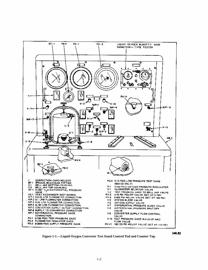
Figure 1-1.—Liquid Oxygen Converter Test Stand ControI Pad and Counter Top.
1-2
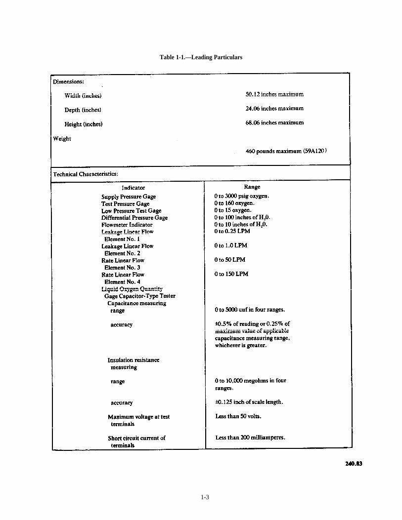
Table 1-1.—Leading Particulars
1-3
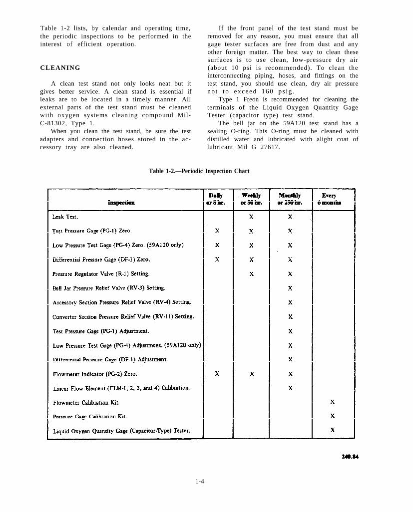
Table 1-2 lists, by calendar and operating time,the periodic inspections to be performed in theinterest of efficient operation.
CLEANING
A clean test stand not only looks neat but itgives better service. A clean stand is essential ifleaks are to be located in a timely manner. Allexternal parts of the test stand must be cleanedwith oxygen systems cleaning compound Mil-C-81302, Type 1.
When you clean the test stand, be sure the testadapters and connection hoses stored in the ac-cessory tray are also cleaned.
If the front panel of the test stand must beremoved for any reason, you must ensure that allgage tester surfaces are free from dust and anyother foreign matter. The best way to clean thesesurfaces is to use clean, low-pressure dry air(about 10 psi is recommended). To clean theinterconnecting piping, hoses, and fittings on thetest stand, you should use clean, dry air pressuren o t t o e x c e e d 1 6 0 p s i g .
Type 1 Freon is recommended for cleaning theterminals of the Liquid Oxygen Quantity GageTester (capacitor type) test stand.
The bell jar on the 59A120 test stand has asealing O-ring. This O-ring must be cleaned withdistilled water and lubricated with alight coat oflubricant Mil G 27617.
Table 1-2.—Periodic Inspection Chart
1-4
W A R N I N G
Never apply oi l , grease, or any othermater ia l not approved for use in thepresence of gaseous and liquid oxygensystems.
CORRECTION CARD PREPARATIONAND CALIBRATION
An on-site CAL TEAM must prepare theco r r ec t i on ca rd s and ca l i b r a t e t he 59A120f o l l o w i n g N A V A I R 1 3 - 1 - 6 . 4 p r o c e d u r e s .Howeve r , because o f t he ope ra t i ona l com-mitments of today’s Navy, you may find yourselfwith a test s tand that needs cal ibrat ion andcorrection card corrections when CAL TEAMservices are not available. This chapter coverst h e p r o c e d u r e s o u t l i n e d i n t h e N A V A I R17-15BC-20 for correction card preparation andcalibration.
NOTE: This RTM does not authorize you tocalibrate the test stand nor does it authorize youto make correction card corrections. These tasks
CORRECTION CARDS
Before you operate the 59A120 test stand,individual correction cards for the followingcomponents must be prepared: DF-1, PG-1,PG-4, FLM-1, FLM-2, FLM-3, and FLM-4.These correction cards must be prepared prior tocalibration of the 59A120 test stand.To perform calibration and to prepare correctioncards, you will need the Flowmeter CalibrationKit and the four graphs that are supplied with thekit for that particular test stand. Each kit will beserialized with the same number as the serialnumber of the test stand.
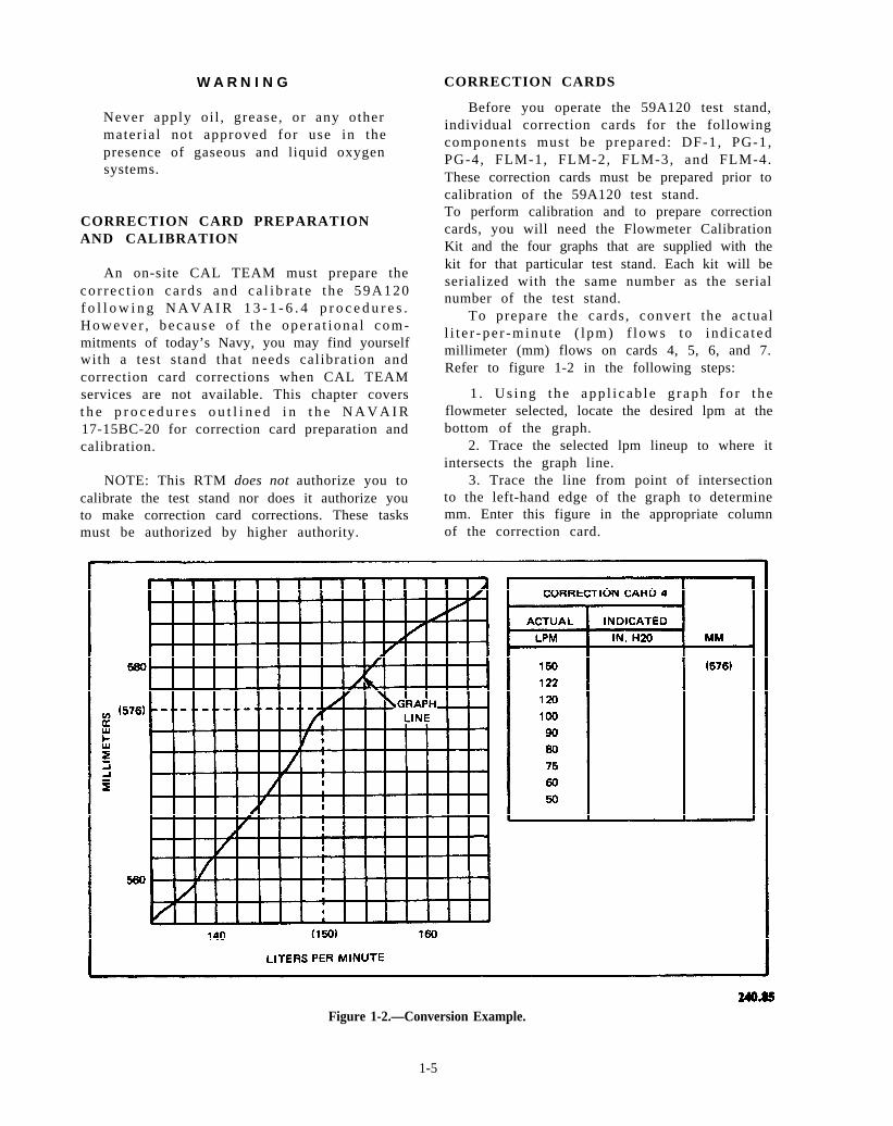
To prepare the cards, convert the actuall i t e r -pe r -minu te ( l pm) f l ows to i nd i ca t edmillimeter (mm) flows on cards 4, 5, 6, and 7.Refer to figure 1-2 in the following steps:
1 . Us ing t he app l i c ab l e g r aph fo r t heflowmeter selected, locate the desired lpm at thebottom of the graph.
2. Trace the selected lpm lineup to where itintersects the graph line.
3. Trace the line from point of intersectionto the left-hand edge of the graph to determinemm. Enter this figure in the appropriate column
must be authorized by higher authority. of the correction card.
Figure 1-2.—Conversion Example.
1-5
4. Using applicable graphs, repeat steps 1through 3 for all actual flows given on correctioncards 4 through 7.
5. Indicated flows (in. H2O) are entered onthe cards when you calibrate the test stand.
Differential Pressure Gage (DF-1)
To prepare the differential pressure gage(DF-1) correction card, refer to figure 1-1 in thefollowing steps:
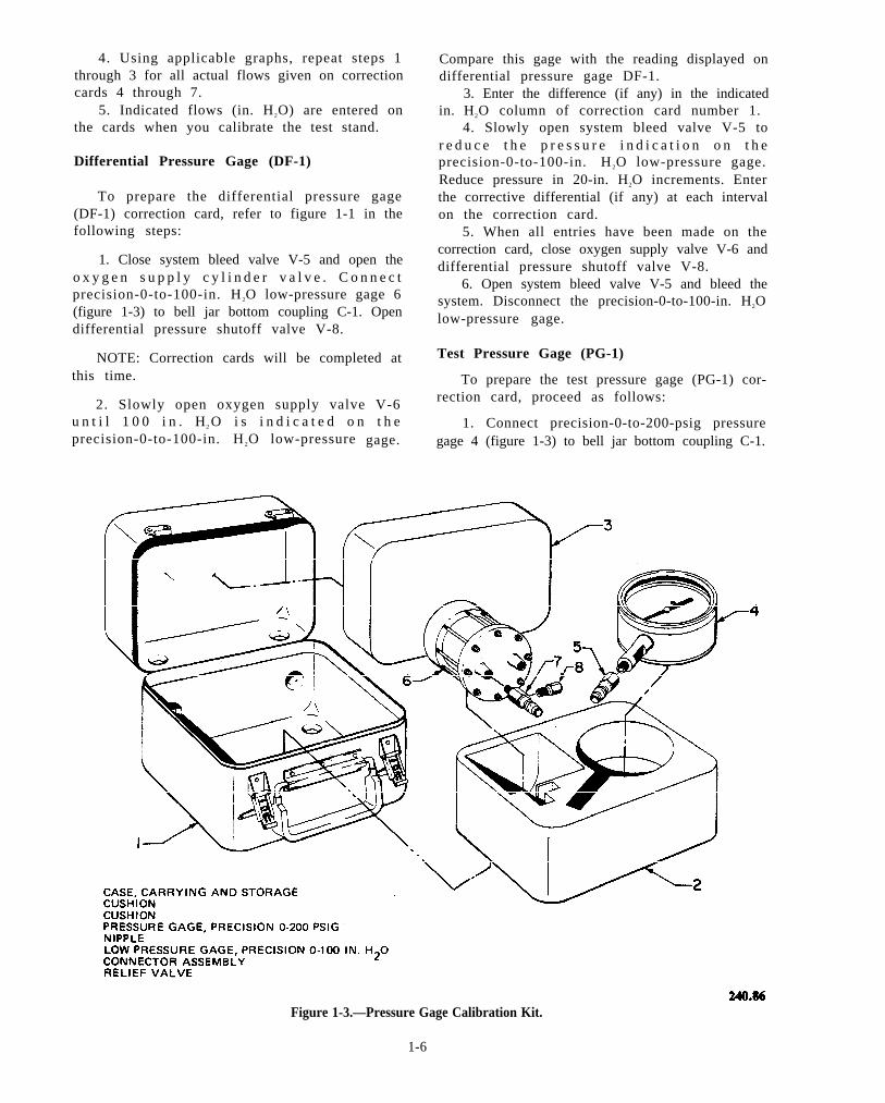
1. Close system bleed valve V-5 and open theo x y g e n s u p p l y c y l i n d e r v a l v e . C o n n e c tprecision-0-to-100-in. H 2O low-pressure gage 6(figure 1-3) to bell jar bottom coupling C-1. Opendifferential pressure shutoff valve V-8.
NOTE: Correction cards will be completed atthis time.
2. Slowly open oxygen supply valve V-6u n t i l 1 0 0 i n . H2 O i s i n d i c a t e d o n t h eprecision-0-to-100-in. H 2O low-pressure gage.
Compare this gage with the reading displayed ondifferential pressure gage DF-1.
3. Enter the difference (if any) in the indicatedin. H2O column of correction card number 1.
4. Slowly open system bleed valve V-5 tor e d u c e t h e p r e s s u r e i n d i c a t i o n o n t h eprecision-0-to-100-in. H 2O low-pressure gage.Reduce pressure in 20-in. H2O increments. Enterthe corrective differential (if any) at each intervalon the correction card.
5. When all entries have been made on thecorrection card, close oxygen supply valve V-6 anddifferential pressure shutoff valve V-8.
6. Open system bleed valve V-5 and bleed thesystem. Disconnect the precision-0-to-100-in. H2Olow-pressure gage.
Test Pressure Gage (PG-1)
To prepare the test pressure gage (PG-1) cor-rection card, proceed as follows:
1. Connect precision-0-to-200-psig pressuregage 4 (figure 1-3) to bell jar bottom coupling C-1.
Figure 1-3.—Pressure Gage Calibration Kit.
1-6
Close system bleed valve V-5, and open testpressure gage to bell jar valve V-2.
2. Open oxygen supply valve V-6 until 160psig registers on the precision-0-to-200-psigpressure gage; then close valve V-6.
3 . C o m p a r e t h e p r e c i s i o n - 0 - t o - 2 0 0 - p s i gpressure gage reading with pressure registered ontest pressure gage PG-1. Enter the correctivedifferential (if any) in the indicated psig columnof test stand correction card number 2.
4. Slowly open system bleed valve V-5 tor e d u c e t h e p r e s s u r e r e g i s t e r e d o n t h eprecision-0-to-200-psig pressure gage. Enter thecorrective differential (if any) at each specifiedpressure on the test stand correction card.
5. After all correction card entries have beencompleted, close system bleed valve V-5 andoxygen supply valve V-6.
Low-Pressure Test Gage (PG-4)
To prepare a low-pressure test gage (PG-4)correction card, proceed as follows:
1. With precision-0-to-200-psig test gage 4(figure 1-3) still attached to bell jar bottomcoupling C-1, open oxygen supply valve V-6until 7.5 psig is indicated on the precision-0-to-200-psig test gage. The pointer of low-pressure
test gage PG-4 should be at midscale. If thepointer is not at midscale, adjust by turning theadjustment screw on the back of the gage.
2. Slowly open oxygen supply valve V-6until 14 psig registers on the precision-0-to-200-psig test gage; then close oxygen supply valve V-6.Compare the reading with the indicat ion onlow-pressure test gage PG-4. Enter the correctivedifferential (if any) in the indicated psig columnof test stand correction card number 3.
3. Slowly open system bleed valve V-5 andr e d u c e t h e p r e s s u r e i n d i c a t e d o n t h eprecision-0-to-200-psig pressure test gage in 2-psigincrements. At each increment, enter the correc-tive differential (if any) on the test stand correc-tion card.
4. After all correction card entries have beencompleted, ensure oxygen supply valve V-6 isclosed; then open system bleed valve V-5 and closetest-pressure-gage-to-bell-jar valve V-2. Removethe precision-0-to-200-psig test gage from bell jarbase coupling C-1. .
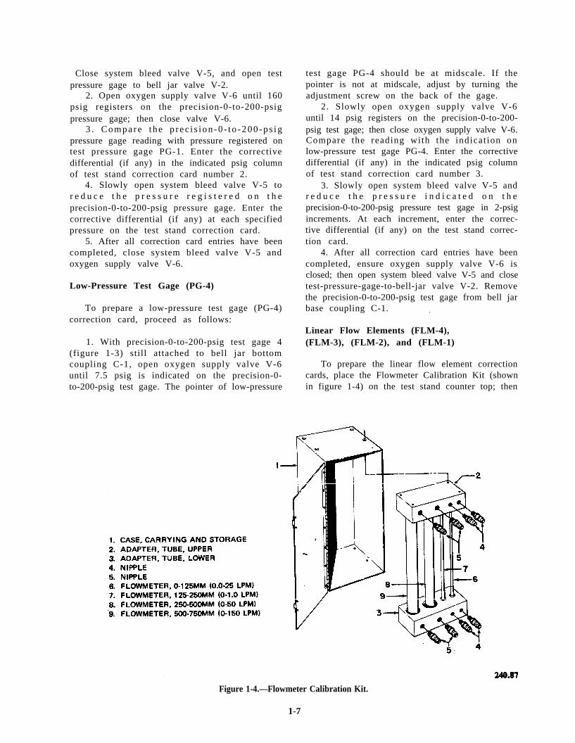
Linear Flow Elements (FLM-4),(FLM-3), (FLM-2), and (FLM-1)
To prepare the linear flow element correctioncards, place the Flowmeter Calibration Kit (shownin figure 1-4) on the test stand counter top; then
Figure 1-4.—Flowmeter Calibration Kit.
1-7
beginning with the 0-to-150-lpm flow element(FLM-4), proceed as follows:
1. Using hose assembly 3 (figure 1-5), con-nect the top connection of the 500-to-750-mmcalibration kit flowmeter 9 (figure 4-4) to teststand flow element connection NIP-4. Using hoseassembly 6 (figure 1-5), connect the bottom con-nection of the calibration kit flowmeter to bell jarbase coupling C-1.
2. Set flowmeter selector valve V-1 to the0-to-150-lpm position. Ensure system bleed valveV-5 is closed.
NOTE: Flows used shall be taken from themm column of the calibration correction cards.This previously completed column contains flowsin millimeters (mm) equivalent to correspondinglpm flows.
3. Using oxygen supply valve V-6, set theflow equivalent to 150 lpm (from correction cardnumber 4) on the 500-to-750-mm calibration kitflow element. The flow, in inches H 2O, will bedisplayed on flowmeter indicator PG-2. Enter thisreading in the indicated in. H 2O c o l u m n o fcorrection card number 4 opposite the actual mmflow being drawn.
4. Reduce the flow to the next millimeterreading by adjusting oxygen supply valve V-6.Repeat step 3. Continue in this manner until allflows on correction card number 4 have beencompleted.
5. Close oxygen supply valve V-6 and discon-nect the hose and the calibration kit flowmeterfrom the test stand.
NOTE: Hose assembly 3 (figure 1-5) and hoseassembly 6 are used in calibrating all linear flowelements.
6 . Connec t t he t op connec t i on o f t he250-to-500-mm calibration kit flowmeter to teststand flow element connection NIP-3; connect thebottom connection to bell jar base coupling C-1.Rotate f lowmeter selector valve V-1 to the0-to-50-lpm position. Ensure system bleed valveV-5 is closed.
7. Repeat procedures outlined in steps 3through 5, using flows given on correction cardnumber 5.
8 . Connec t t he t op connec t i on o f t he125-to-250-mm calibration kit flowmeter to teststand flow element connection NIP-2; connect the
bottom connection to bell jar coupling C-1.Rotate f lowmeter selector valve V-1 to the0-to-1.0-lpm position. Ensure system bleed valveV-5 is closed.
9. Repeat procedures outlined in steps 3through 5, using flows given on correction cardnumber 6.
10 . Connec t t he t op connec t i on o f t he0-to-125-mm calibration kit flowmeter to teststand flow element connection NIP-1; connect thebottom connection to bell jar base coupling C-1.Rotate f lowmeter selector valve V-1 to the0.0-to-0.25-lpm position. Ensure system bleedvalve V-5 is closed.
11. Repeat procedures outlined in steps 3through 5, using flows given on correction cardnumber 7.
12. Disconnect hoses 3 and 6 (figure 1-5) fromthe calibration kit and test stand. Close oxygensupply cylinder valve V-6 and open system bleedvalve V-5 to bleed the test stand. Secure all teststand valves.
TROUBLESHOOTING
A properly working test stand will give yououtstanding results while testing oxygen con-verters. As with any test stand, a small leak inyour plumbing system will give you inaccuratereadings and may cause you to think you havea defective converter or component. Some partson the 59A120 test stand must be corrected whenthey become defective by the on-site meteorologycalibration team. You might have a gage that hasa pointer which isn’t zeroed, or you might havea flow element that consistently reads low. Youcould also have a gage that provides correctreadings over only part of the scale. In such cases,you will need the calibration team’s assistance torepair the component.
Upon completion of any maintenance action,you will be required to fill out a Ground SupportEquipment Subcustody and Periodic MaintenanceRecord (OPNAV 4790/50) and a Ground SupportEquipment Custody and Maintenance Record(OPNAV 4790/51).
The following problems may occur withinyour test stand; you, as a senior PR, will ber e q u i r e d t o f i x t h e m . R e f e r t o N A V A I R17-15BC-20 for parts removal and replacement.
PG-1 Reads Low
The 0-160 psig pressure gage is used to indicatepressure applied to an item under test. Anytime
1-8
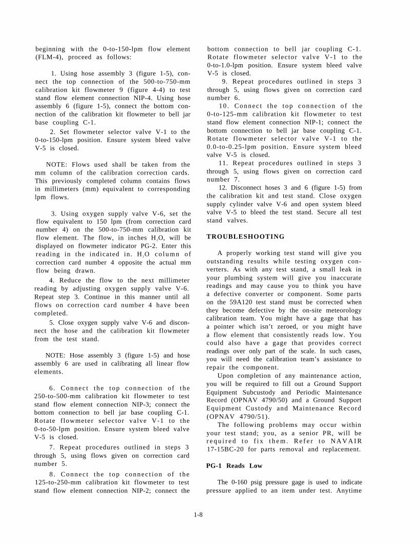
Figure 1-5.—Test Stand Accessories.
1-9
this gage consistently reads low, you probablyhave leaky fittings. To correct this problem, youwill need to perform one or two leakage tests.
To perform leakage tests, pressurize the systemand apply a soap solution to the various fittings.Escaping gas will form soap bubbles, and you canlocate the leaks.
Leakage Test, Accessories Section
To perform the leakage test on the accessoriessection of the test stand, proceed as follows:
1. Install nipple assembly 14 (figure 1-5) inbell jar bottom coupling C-1. Connect one endof hose 3 (figure 1-5) to the adapter and the otherend to differential pressure connection NIP-7.
2. Ensure test-pressure-gage-to-bell-jar valveV-2 is open. Ensure system bleed valve V-5, testpressure gage build-up and vent valve V-10, anddifferential pressure bleed valve V-7 are closed.
3. Open differential pressure shutoff valveV-8.
4. Open oxygen supply cylinder valve. Openoxygen supply valve V-6 until 160 psig is indicatedon test pressure gage PG-1.
5. Close oxygen supply valve V-6. Leakagewill be indicated by a drop in pressure on PG-1.Leakage must not be more than 2 psig in 10minutes.
6. Leave all hoses and valves in their presentposition.
Leakage Test, Test Stand
To perform the leakage test on the entire teststand, proceed as follows:
1. Open converter supply flow control valveV-9 and test pressure gage build-up and flow valveV-10.
2. Plug converter supply outlet NIP-5 andsupply to converter connection NIP-6. Ensuresystem bleed valve V-5 is closed.
3. Open supply valve V-6 until relief valveV-11 unseats. (Relief valve shall relieve at no morethan 120 psig and be leak-tight at 100 psig.)Using system bleed valve V-5, decrease pressureuntil 100 psig is indicated on test pressure gagePG-1. Close valve V-6. Leakage will be indicatedby a drop in pressure on PG-1. Leakage shall beno more than 10 psig in 10 minutes.
4. Bleed the test stand by opening systembleed valve V-5. Close all test stand valves.Remove plugs from converter supply outlet NIP-5and supply to converter connection NIP-6.
PG-1 Pointer Pegs
Anytime the 0-160 psig pressure gage pegs, itis caused by pressure regulator R-1. This pressureregulator is set to maintain 160 psig with 1800 psigsupply pressure applied. If the PG-1 pressure gagepegs, your regulator is delivering pressure above160 psig and the pressure must be adjusted.
To set oxygen pressure regulator R-1 tomaintain 160 psig with 1800 psig supply pressureapplied, proceed as follows:
CAUTION
Valves V-2, V-5, V-6, V-7, and V-10 aremetering (needle) valves. Overtighteningwhen closing will damage valve seat. Onlyfinger-tight pressure should be used whenclosing valves.
1. Ensure all test stand valves are closed, andplug bell jar bottom coupling C-1.
W A R N I N G
When you are working with oxygen, makecertain that clothing, tubing, fittings, andequipment are free of oil, grease, fuel,h y d r a u l i c f l u i d , o r a n y c o m b u s t i b l ematerials. When oxygen is under pressure,fire or explosion may result when evenslight traces of combustible materials comein contact.
2. Open oxygen supply cylinder valve.
N O T E : W h e n s e t t i n g r e g u l a t o r R - 1 , aminimum of 1800 psig oxygen pressure should beapplied to the regulator.
3. Slowly open test-pressure-gage-to-bell-jarvalve V-2, and fully open oxygen supply valveV-6.
4. Loosen the hex locknut located on the frontof regulator R-1. Turn the T-handle until 160 psigregisters on test pressure gage PG-1. Tighten thehex locknut.
5. Close the oxygen supply cylinder valve andopen system bleed valve V-5 to bleed pressurefrom system. Remove the plug from bell jar bot-tom coupling C-1.
1-10
PG-4 Indicates LowReadings Consistently
The 0-15 psig pressure gage PG-4 measuresextremely low pressures from the item under test.This gage is protected from high pressures by gageguard GP-1, which is set between 11 and 14 psig.To locate any leaks in this system, you will needto perform the leakage test described earlier forthe test s tand. You wil l not be required toperform the leakage test for the accessoriessection. In most cases by tightening the necessaryfittings, you will be able to remedy the lowreadings on the PG-1 pressure gage.
Differential Pressure Gage(DF-1) Indicates Low
The 0-100-in. H2O differential pressure gageis a bel lows-operated gage used to indicatedifferential pressure when the pressure closing andpressure opening valves are tested. The probablecause for low readings on this gage is a leaky shutoff differential pressure valve V-8. If you arelucky, you can correct it by tightening the fittings.If this does not solve the problem, you will needto replace the valve.
Bell Jar Leakage
You may also have problems with the bell jar.The bel l jar is used for tes t ing componentshaving more than one possible area of leakage.The bell jar consists of the bell jar itself, a reliefvalve with a range of 5 to 15 psig, and a bell jarcoupling. The relief valve is designed to beleakproof at 5 psi and set to relieve at 10 psig.
To perform the leakage test on the bell jarassembly, proceed as follows:
1. Remove hose assembly 3 and nippleassembly 14 (figure 1-5) from the bottom bell jarcoupling C-1. Disconnect the opposite end of thehose from differential pressure connection NIP-7.
2. Ensure differential pressure bleed valveV-7, test-pressure-gage-to-bell-jar valve V-2, andsystem bleed valve V-5 are closed. Open differen-tial pressure shutoff valve V-8.
3. Place the bell jar on the fixture and secureit with a clamp. Plug bell jar top coupling C-2.
4. Slowly open oxygen supply valve V-6until 100 in. H 2O is indicated on differentialpressure gage DF-1. Close valve V-6. Leakage,indicated by a drop in pressure on DF-1, shall notbe more than 2 in. H2O in 10 minutes.
5. Close the oxygen supply cylinder valve andopen system bleed valve V-5 to bleed the system.
CAUTION
When the test stand is secured, all valveswith the exception of system bleed valveV-5 will be closed. Valve V-5 is left opento prevent accidental build-up of pressurein the system.
6. Secure all test stand valves. Leave systembleed valve V-5 open.
REPAIRING AND REPLACING PARTS
Anytime you have a defective or damagedpart, it must be repaired or replaced. Informa-t ion on par t numbers can be found in theNAVAIR 17-15BC-20 manual.
Y o u m a y o n o c c a s i o n f i n d y o u h a v e adefective piece of tubing. To replace any tubinginstalled on this test stand (59A120), rememberthat you are dealing with high-pressure oxygen.Therefore, you must use tubing with a minimumwall thickness of 0.049 to replace any defectivetubing. This tubing may be cut to length andflared to replace any defective portion of tubing.
W A R N I N G
When you work with oxygen systems,never use any parts that have been in con-tact with oil, grease, or any other materialthat is not approved for use in the presenceof high-pressure oxygen. Fire or explosionmay result when even the slightest trace ofcombustible material comes in contact withpressurized oxygen.
Heat Exchanger Panel
If the heat exchanger panel is defective, it maybe replaced. You may replace the panel by discon-necting its connections and removing it’s sevenretaining screws. If a new heat exchanger isused, you may drill or punch holes not exceeding11/32 inch in diameter in the perimeter, beyondthe outer seam welds, for use in mounting. Whenthe holes are drilled at installation, you shouldbe careful to prevent the drill from puncturing theseam welds.
Lubrication
The test stand nor its components requirelubrication.
1-11

CHAPTER 2
OXYGEN COMPONENT TESTSTAND (1172AS100)
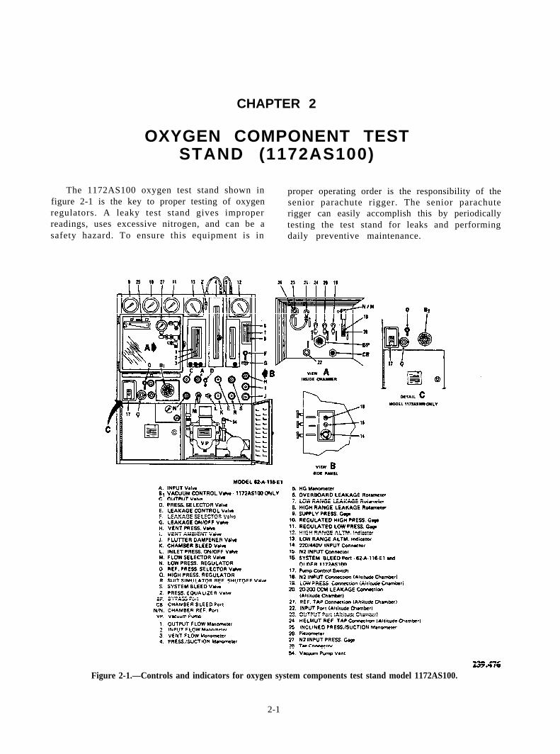
The 1172AS100 oxygen test stand shown infigure 2-1 is the key to proper testing of oxygenregulators. A leaky test stand gives improperreadings, uses excessive nitrogen, and can be asafety hazard. To ensure this equipment is in
proper operating order is the responsibility of thesenior parachute rigger. The senior parachuterigger can easily accomplish this by periodicallytesting the test stand for leaks and performingdaily preventive maintenance.
Figure 2-1.—Controls and indicators for oxygen system components test stand model 1172AS100.
2-1
PERIODIC INSPECTIONS
Daily, weekly, biweekly, and monthly in-spections are required. Detailed instructions areoutlined in the NAVAIR 13-1-6.4 and the AircrewSurvival Equipmentman 3 & 2, Volume 2.
As you read this chapter, you will notice thatwe use references such as F, 19, E, and so forth.These reference numbers and letters are found infigure 2-1. Also remember that the 1172AS100 teststand is a modified version of the old 62A116E1test stand; so don’t get them confused.
TROUBLESHOOTING THE 1172AS100TEST STAND FOR LEAKS
As you have already read, leaks will probablycause you the most problems in troubleshooting.Locating a leak in one system is easier thanrandom troubleshooting all systems for a leak.Nine different systems are incorporated within the1172AS100 oxygen system component test stand.Some of the systems are interconnected and usedsimultaneously with other systems; therefore, youmust be familiar with each system.
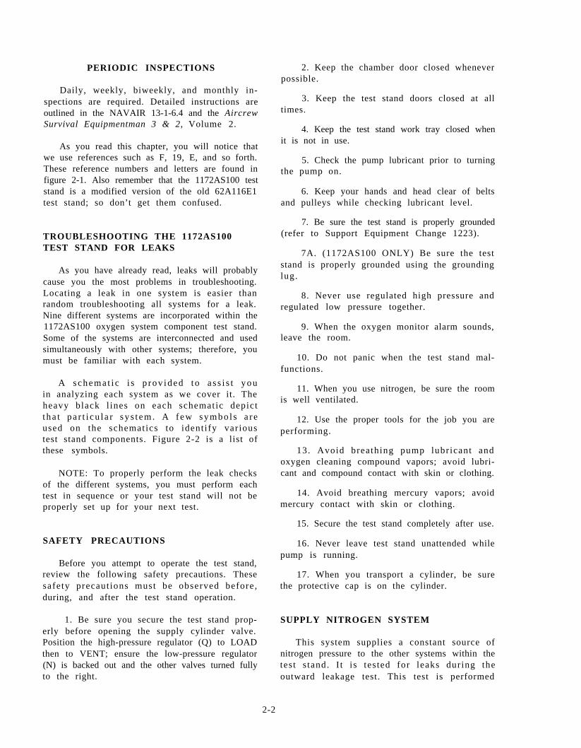
A schema t i c i s p rov ided t o a s s i s t youin analyzing each system as we cover it. Theheavy black l ines on each schematic depictt ha t pa r t i cu l a r sy s t em. A f ew symbo l s a r eused on the schematics to ident i fy var ioustest stand components. Figure 2-2 is a list ofthese symbols.
NOTE: To properly perform the leak checksof the different systems, you must perform eachtest in sequence or your test stand will not beproperly set up for your next test.
SAFETY PRECAUTIONS
Before you attempt to operate the test stand,review the following safety precautions. Thesesafety precaut ions must be observed before ,during, and after the test stand operation.
1. Be sure you secure the test stand prop-erly before opening the supply cylinder valve.Position the high-pressure regulator (Q) to LOADthen to VENT; ensure the low-pressure regulator(N) is backed out and the other valves turned fullyto the right.
2. Keep the chamber door closed wheneverpossible.
3. Keep the test stand doors closed at alltimes.
4. Keep the test stand work tray closed whenit is not in use.
5. Check the pump lubricant prior to turningthe pump on.
6. Keep your hands and head clear of beltsand pulleys while checking lubricant level.
7. Be sure the test stand is properly grounded(refer to Support Equipment Change 1223).
7A. (1172AS100 ONLY) Be sure the teststand is properly grounded using the groundinglug.
8. Never use regulated high pressure andregulated low pressure together.
9. When the oxygen monitor alarm sounds,leave the room.
10. Do not panic when the test stand mal-functions.
11. When you use nitrogen, be sure the roomis well ventilated.
12. Use the proper tools for the job you areperforming.
13. Avoid breathing pump lubricant andoxygen cleaning compound vapors; avoid lubri-cant and compound contact with skin or clothing.
14. Avoid breathing mercury vapors; avoidmercury contact with skin or clothing.
15. Secure the test stand completely after use.
16. Never leave test stand unattended whilepump is running.
17. When you transport a cylinder, be surethe protective cap is on the cylinder.
SUPPLY NITROGEN SYSTEM
This system supplies a constant source ofnitrogen pressure to the other systems within thetest s tand. I t is tes ted for leaks during theoutward leakage test. This test is performed
2-2
Figure 2-2.—Test stand schematic symbols.
2-3
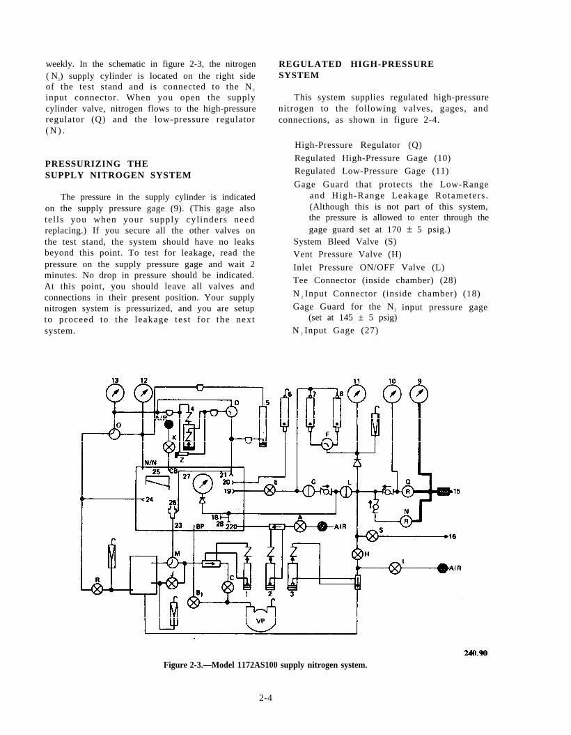
weekly. In the schematic in figure 2-3, the nitrogen( N2) supply cylinder is located on the right sideof the test stand and is connected to the N 2
input connector. When you open the supplycylinder valve, nitrogen flows to the high-pressureregulator (Q) and the low-pressure regulator( N ) .
PRESSURIZING THESUPPLY NITROGEN SYSTEM
The pressure in the supply cylinder is indicatedon the supply pressure gage (9). (This gage alsotel ls you when your supply cyl inders needreplacing.) If you secure all the other valves onthe test stand, the system should have no leaksbeyond this point. To test for leakage, read thepressure on the supply pressure gage and wait 2minutes. No drop in pressure should be indicated.At this point, you should leave all valves andconnections in their present position. Your supplynitrogen system is pressurized, and you are setupto proceed to the leakage test for the nextsystem.
REGULATED HIGH-PRESSURESYSTEM
This system supplies regulated high-pressurenitrogen to the following valves, gages, andconnections, as shown in figure 2-4.
High-Pressure Regulator (Q)
Regulated High-Pressure Gage (10)
Regulated Low-Pressure Gage (11)
Gage Guard that protects the Low-Rangeand High-Range Leakage Rotameters .(Although this is not part of this system,the pressure is allowed to enter through thegage guard set at 170 ± 5 psig.)
System Bleed Valve (S)Vent Pressure Valve (H)
Inlet Pressure ON/OFF Valve (L)
Tee Connector (inside chamber) (28)
N 2 Input Connector (inside chamber) (18)
Gage Guard for the N2
(set at 145 ± 5 psig)
N 2 Input Gage (27)
input pressure gage
Figure 2-3.—Model 1172AS100 supply nitrogen system.
2-4
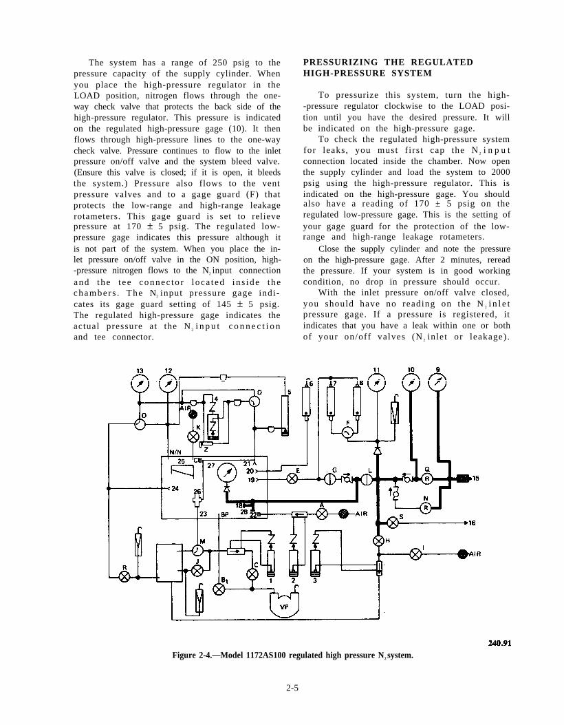
The system has a range of 250 psig to thepressure capacity of the supply cylinder. Whenyou place the high-pressure regulator in theLOAD position, nitrogen flows through the one-way check valve that protects the back side of thehigh-pressure regulator. This pressure is indicatedon the regulated high-pressure gage (10). It thenflows through high-pressure lines to the one-waycheck valve. Pressure continues to flow to the inletpressure on/off valve and the system bleed valve.(Ensure this valve is closed; if it is open, it bleedsthe system.) Pressure also flows to the ventpressure valves and to a gage guard (F) thatprotects the low-range and high-range leakagerotameters. This gage guard is set to relievepressure at 170 ± 5 psig. The regulated low-pressure gage indicates this pressure although itis not part of the system. When you place the in-let pressure on/off valve in the ON position, high--pressure nitrogen flows to the N2 input connectionand the t ee connec to r l oca t ed i n s ide t hechamber s . The N2 input pressure gage indi-cates its gage guard setting of 145 ± 5 psig.The regulated high-pressure gage indicates theactual pressure at the N 2 i n p u t c o n n e c t i o nand tee connector.
PRESSURIZING THE REGULATEDHIGH-PRESSURE SYSTEM
To pressurize this system, turn the high--pressure regulator clockwise to the LOAD posi-tion until you have the desired pressure. It willbe indicated on the high-pressure gage.
To check the regulated high-pressure systemfor leaks, you must f i rs t cap the N 2 i n p u tconnection located inside the chamber. Now openthe supply cylinder and load the system to 2000psig using the high-pressure regulator. This isindicated on the high-pressure gage. You shouldalso have a reading of 170 ± 5 psig on theregulated low-pressure gage. This is the setting ofyour gage guard for the protection of the low-range and high-range leakage rotameters.
Close the supply cylinder and note the pressureon the high-pressure gage. After 2 minutes, rereadthe pressure. If your system is in good workingcondition, no drop in pressure should occur.
With the inlet pressure on/off valve closed,you should have no reading on the N 2 i n l e tpressure gage. If a pressure is registered, itindicates that you have a leak within one or bothof your on/off valves (N 2 inlet or leakage) .
Figure 2-4.—Model 1172AS100 regulated high pressure N2 system.
2-5
A pressure drop on the regulated low-pressuregage indicates that the leakage on/off valve isleaking. This completes your leakage check. Youmust bleed the system by turning the high-pressureregulator to the VENT position until the high--pressure gage reads zero and then open the systembleed valve. This bleeds all remaining lines.
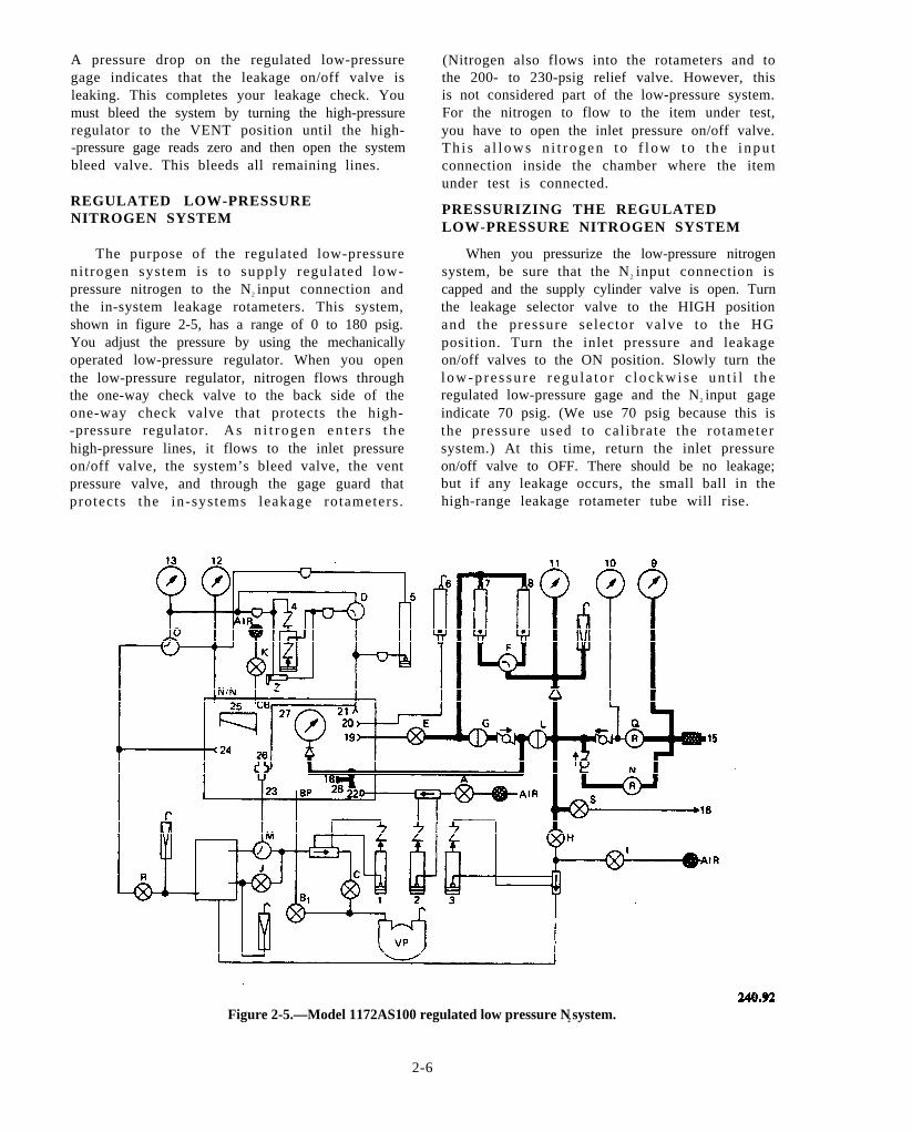
REGULATED LOW-PRESSURENITROGEN SYSTEM
The purpose of the regulated low-pressureni trogen system is to supply regulated low-pressure nitrogen to the N2 input connection andthe in-system leakage rotameters. This system,shown in figure 2-5, has a range of 0 to 180 psig.You adjust the pressure by using the mechanicallyoperated low-pressure regulator. When you openthe low-pressure regulator, nitrogen flows throughthe one-way check valve to the back side of theone-way check valve that protects the high--pressure regulator. As n i t r ogen en t e r s t hehigh-pressure lines, it flows to the inlet pressureon/off valve, the system’s bleed valve, the ventpressure valve, and through the gage guard thatprotects the in-systems leakage rotameters .
(Nitrogen also flows into the rotameters and tothe 200- to 230-psig relief valve. However, thisis not considered part of the low-pressure system.For the nitrogen to flow to the item under test,you have to open the inlet pressure on/off valve.Th i s a l l ows n i t r ogen t o f l ow to t he i npu tconnection inside the chamber where the itemunder test is connected.
PRESSURIZING THE REGULATEDLOW-PRESSURE NITROGEN SYSTEM
When you pressurize the low-pressure nitrogensystem, be sure that the N2 input connection iscapped and the supply cylinder valve is open. Turnthe leakage selector valve to the HIGH positionand the pressure selector valve to the HGposition. Turn the inlet pressure and leakageon/off valves to the ON position. Slowly turn thelow-p re s su re r egu l a to r c lockwi se un t i l t heregulated low-pressure gage and the N2 input gageindicate 70 psig. (We use 70 psig because this isthe pressure used to cal ibrate the rotametersystem.) At this time, return the inlet pressureon/off valve to OFF. There should be no leakage;but if any leakage occurs, the small ball in thehigh-range leakage rotameter tube will rise.
Figure 2-5.—Model 1172AS100 regulated low pressure N2 system.
2-6
Turn the leakage selector valve to LOWRANGE. No leakage should be indicated on thelow-range rotameter. Return the leakage-selectorvalve to HIGH RANGE and the inlet pressureon/off valve to the ON position.
Slowly open the low-pressure regulator untilthe regulated low-pressure gage indicates 160 psig.(The N2 input pressure gage should read its gageguard pressure of 145 ± 5 psig). Turn the inletpressure on/off valve to OFF. No leakage shouldbe indicated on the high-range leakage rotameter.Turn the leakage selector valve to the LOW-RANGE position. No leakage should be indicatedon the low-range leakage rotameter. Use thesystem bleed valve to decrease the pressure to 70psig. You must turn the low-pressure regulatorcounterclockwise until 70 psig is maintained.Leave the test stand in this condition; it is set upfor you to perform your next leakage test.
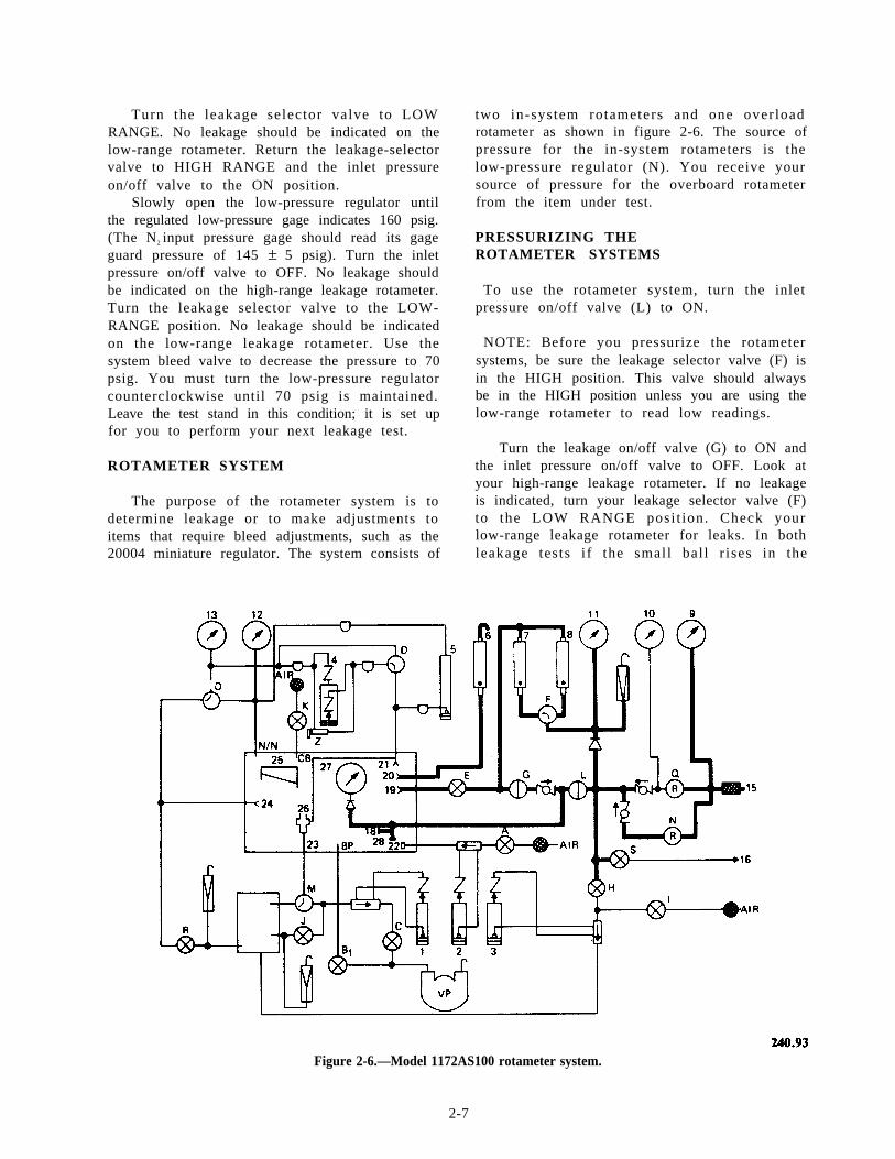
ROTAMETER SYSTEM
The purpose of the rotameter system is todetermine leakage or to make adjustments toitems that require bleed adjustments, such as the20004 miniature regulator. The system consists of
two in-system rotameters and one overloadrotameter as shown in figure 2-6. The source ofpressure for the in-system rotameters is thelow-pressure regulator (N). You receive yoursource of pressure for the overboard rotameterfrom the item under test.
PRESSURIZING THEROTAMETER SYSTEMS
To use the rotameter system, turn the inletpressure on/off valve (L) to ON.
NOTE: Before you pressurize the rotametersystems, be sure the leakage selector valve (F) isin the HIGH position. This valve should alwaysbe in the HIGH position unless you are using thelow-range rotameter to read low readings.
Turn the leakage on/off valve (G) to ON andthe inlet pressure on/off valve to OFF. Look atyour high-range leakage rotameter. If no leakageis indicated, turn your leakage selector valve (F)to the LOW RANGE posi t ion. Check yourlow-range leakage rotameter for leaks. In bothleakage tests i f the small bal l r ises in the
Figure 2-6.—Model 1172AS100 rotameter system.
2-7
rotameter tube, it indicates a leak. If no leakageis indicated during this test, continue.
Return the leakage selector valve (F) to theHIGH position and turn the leakage on/off valve(G) to the OFF position. By slightly cracking thecap at the N2 input connection, you can bleed anypressure indicated on the N2 input pressure gage(27)
At this time, a line with two bayonet fittingsmust be at tached between the low-pressureconnection (19) and the 200-CCM leakage con-nection (20) inside the chamber. This line is usedto check for any leakage through the leakagecontrol valve (E). Leakage is indicated on theo v e r b o a r d r o t a m e t e r ( G ) . I f n o l e a k a g e i sindicated, remove the side attached to the leakageconnection (20) and attach it to the reference tapconnection (21 ). (This sets your test stand up toperform the differential pressure system test.) Thereference tap connection (21) is also locatedins ide t he chamber . P l ace a cap ove r t hepiezometer and turn the pressure selector valve(D) to the H2O position. Slowly open the leakagecontrol valve (E) unt i l the pressure/suct ionmanometer (4) indicates 9.0 inches of water (in.H 2O). Ful ly c losing this valve (E) may benecessary after you reach 9.0 in. H2O. No leakageshould be indicated on the high-range leakagerotameter (8).
Turn the leakage selector valve (F) to the LOWRANGE position. No leakage should be indicatedon the low-range leakage rotameter (7). Close theleakage control valve (E) and turn the leakage se-lector valve (F) to the HIGH RANGE position.Now disconnect the line at the low-pressure con-nection (19). Bleed the pressure from the pressure/suction manometer (4); then reconnect the lines.
If you find this system has no leakage, yourtest stand is set up to perform the differentialpressure indicating system leakage test.
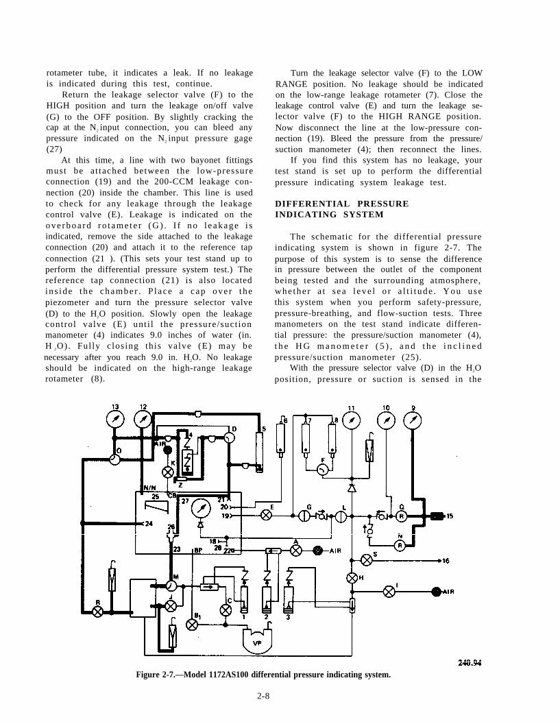
DIFFERENTIAL PRESSUREINDICATING SYSTEM
The schematic for the differential pressureindicating system is shown in figure 2-7. Thepurpose of this system is to sense the differencein pressure between the outlet of the componentbeing tested and the surrounding atmosphere,whe the r a t s ea l eve l o r a l t i t ude . You usethis system when you perform safety-pressure,pressure-breathing, and flow-suction tests. Threemanometers on the test stand indicate differen-tial pressure: the pressure/suction manometer (4),t h e H G m a n o m e t e r ( 5 ) , a n d t h e i n c l i n e dpressure/suction manometer (25).
With the pressure selector valve (D) in the H2Oposition, pressure or suction is sensed in the
Figure 2-7.—Model 1172AS100 differential pressure indicating system.
2-8
piezometer (26) by a line that runs from thereference tap connection (21) to the piezometer(26). The pressure/suction manometer (4) registersthat pressure or suct ion. The pressure a lS O
registers on the HG manometer (5).
NOTE: The HG manometer (5) receivespressure or suction from the piezometer regardlessof the position of the pressure selector valve (D).
From the pressure/suction manometer (4), thepressure flows through another line trap to aconnection at the low-range altimeter (13). It thenflows to the reference pressure selector valve (O).W i t h t h e v a l v e ( O ) i n t h e A L T I T U D ECHAMBER posi t ion, differential pressure istransmitted to the chamber reference port (N/N).
Other valves and connect ions that affectreadings on the pressure/suction manometer (4)are the helmet reference tap (24) , the sui tsimulator reference shutoff valve (R), and thepressure equalizer valve (Z).
The helmet reference tap (24) is used when youtest the full pressure suit helmet. It gives thedifferent ial pressure between the respiratorysection and the suit section. When you test thefull pressure suit controllers, the suit simulatorshutoff valve (R) is used in conjunction with thereference pressure selector valve (O) to give theactual altitudes within the suit. The pressureequalizer valve (Z) equalizes the pressure in thepressure/suct ion manometer (4) as does thepressure selector valve (D) when the pressureselector valve is placed in the HG position.
PRESSURIZING THE DIFFERENTIALPRESSURE INDICATING SYSTEM
NOTE: At this point, knowing that 1.0 psig =27.7 in. H2O or 2.0 in. HG will be helpful to you.
To use the differential pressure indicatingsystem, open the leakage control valve (E) untilthe pressure/suction manometer (4) indicates 16.0in. H2O. Place the leakage selector valve(D) in theHG position. Now close the leakage control valve(E). The system should now be maintaining 16.0in. H2O. If the system has a leak, the high-rangeflowmeter (8) or the low-range flowmeter (7) willindicate it. If the system has no leakage, discon-nect the line between the low-pressure connection(19) and the reference tap connection (21); thenremove the plug from the piezometer.
To b l eed t he sy s t em, back ou t on t helow-pressure regulator (N) and open the bleedvalve (S). After you bleed the system, close thesystem bleed valve (S). Leave all valves andconnections in their present position. Now youare ready to check the vacuum system.
2-9
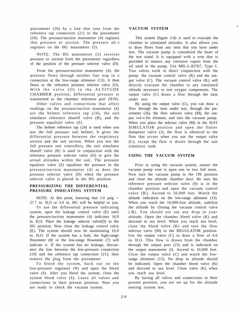
VACUUM SYSTEM#
This system (figure 2-8) is used to evacuate thechamber to simulated altitudes. It also allows youto draw flows from any item that you have undertest. The vacuum pump is considered the heart ofthe test stand. It is equipped with a vent that isprovided to remove any corrosive vapors from theoil used in the pump. Use MIL-L-83767, Type I.Two valves work in direct conjunction with thepump: the vacuum control valve (B l) and the out-put valve (C). The vacuum control valve (B l) willdirectly evacuate the chamber to any simulatedaltitude necessary to test oxygen components. Theoutput valve (C) draws a flow through the itemunder test.
By using the output valve (C), you can draw aflow through the item under test, through the pie-zometer (26), the flow selector valve (M), the out-put vol-o-flo element, and into the vacuum pump.When you place the selector valve (M) in the SUITSIMULATOR posi t ion and open the f lut terdampener valve (J), the flow is identical to theflow that occurs when you use the output valve(C), except the flow is drawn through the suitsimulator tank.
USING THE VACUUM SYSTEM
Prior to using the vacuum system, ensure thevacuum pump vent is open one to two full turns.Now turn the vacuum pump to the ON positionand close the altitude chamber door. Be sure thereference pressure selector valve (0) is in thechamber position and open the vacuum controlvalve (B1). Ascend to 10,000 feet. Watch thealtitude indication on the low-range altimeter (13).When you reach the 10,000-foot altitude, stabilizethe altitude by closing the vacuum control valve( Bl) . You should not see any drop in youraltitude. Open the chamber bleed valve (K) anddescend to sea level. When you reach sea level,close the bleed valve (K) and turn the flowselector valve (M) to the REGULATOR position.Use the output valve (C) to draw a flow of 6.0in. H2O. This flow is drawn from the chamberthrough the output port (23) and is indicated onthe output manometer (l). Ascend to 10,000 feet.Close the output valve (C) and watch the low-range altimeter (13). No drop in altitude shouldbe indicated. Open the chamber bleed valve (K)and descend to sea level. Close valve (K) whenyou reach sea level.
By having all valves and connections in theirpresent position, you are set up for the altitudesensing system test.
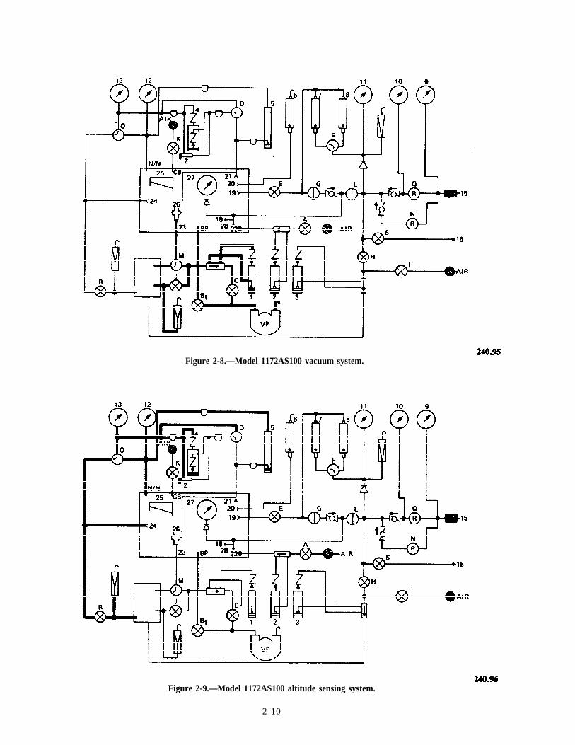
Figure 2-8.—Model 1172AS100 vacuum system.
Figure 2-9.—Model 1172AS100 altitude sensing system.
2-10
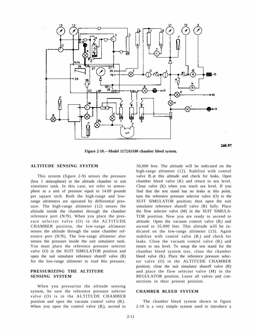
Figure 2-10.—Model 1172AS100 chamber bleed system.
ALTITUDE SENSING SYSTEM
This system (figure 2-9) senses the pressure(less 1 atmosphere) in the altitude chamber or suitsimulator tank. In this case, we refer to atmos-phere as a unit of pressure equal to 14.69 poundsper square inch. Both the high-range and low-range altimeters are operated by differential pres-sure. The high-range altimeter (12) senses thealtitude inside the chamber through the chamberreference port (N/N). When you place the pres-su re s e l ec to r va lve (O) i n t he ALTITUDECHAMBER position, the low-range altimetersenses the altitude through the same chamber ref-erence port (N/N). The low-range altimeter alsosenses the pressure inside the suit simulator tank.You must place the reference pressure selectorvalve (O) in the SUIT SIMULATOR position andopen the suit simulator reference shutoff valve (R)for the low-range altimeter to read this pressure.
PRESSURIZING THE ALTITUDESENSING SYSTEM
When you pressurize the altitude sensingsystem, be sure the reference pressure selectorvalve (O) is in the ALTITUDE CHAMBERposition and open the vacuum control valve (B l) .When you open the control valve (B l), ascend to
50,000 feet. The altitude will be indicated on thehigh-range altimeter (12). Stabilize with controlvalve B1 at this altitude and check for leaks. Openchamber bleed valve (K) and return to sea level.Close valve (K) when you reach sea level. If youfind that the test stand has no leaks at this point,turn the reference pressure selector valve (O) to theSUIT SIMULATOR position; then open the suitsimulator reference shutoff valve (R) fully. Placethe flow selector valve (M) in the SUIT SIMULA-TOR position. Now you are ready to ascend toaltitude. Open the vacuum control valve (B l) andascend to 35,000 feet. This altitude will be in-dicated on the low-range altimeter (13). Againstabilize with control valve (B1) and check forleaks. Close the vacuum control valve (B l) andreturn to sea level. To setup the test stand for thechamber bleed system test, close the chamberbleed valve (K). Place the reference pressure selec-tor valve (O) in the ALTITUDE CHAMBERposition; close the suit simulator shutoff valve (R)and place the flow selector valve (M) in theREGULATOR position. Leave all valves and con-nections in their present position.
CHAMBER BLEED SYSTEM
The chamber bleed system shown in figure2-10 is a very simple system used to introduce a
2-11
large volume of air into the altitude chamber.When you open the chamber bleed valve (K),ambient air flows into the chamber through thechamber bleed port (CB). The altitude in thechamber drops unt i l the pressure inside thechamber equalizes with the pressure at sea level.
PRESSURIZING THE CHAMBERBLEED SYSTEM
Open the vacuum control valve (B1) andascend to 10,000 feet; then close the valve tostabilize your altitude. A drop in altitude on thelow-range altimeter (13) indicates a leak. If thereis no drop in altitude, open the chamber bleedvalve (K) and descend to sea level. When youreach sea level, close the chamber bleed valve (K).The test stand is now ready to test the flowmeasuring system.
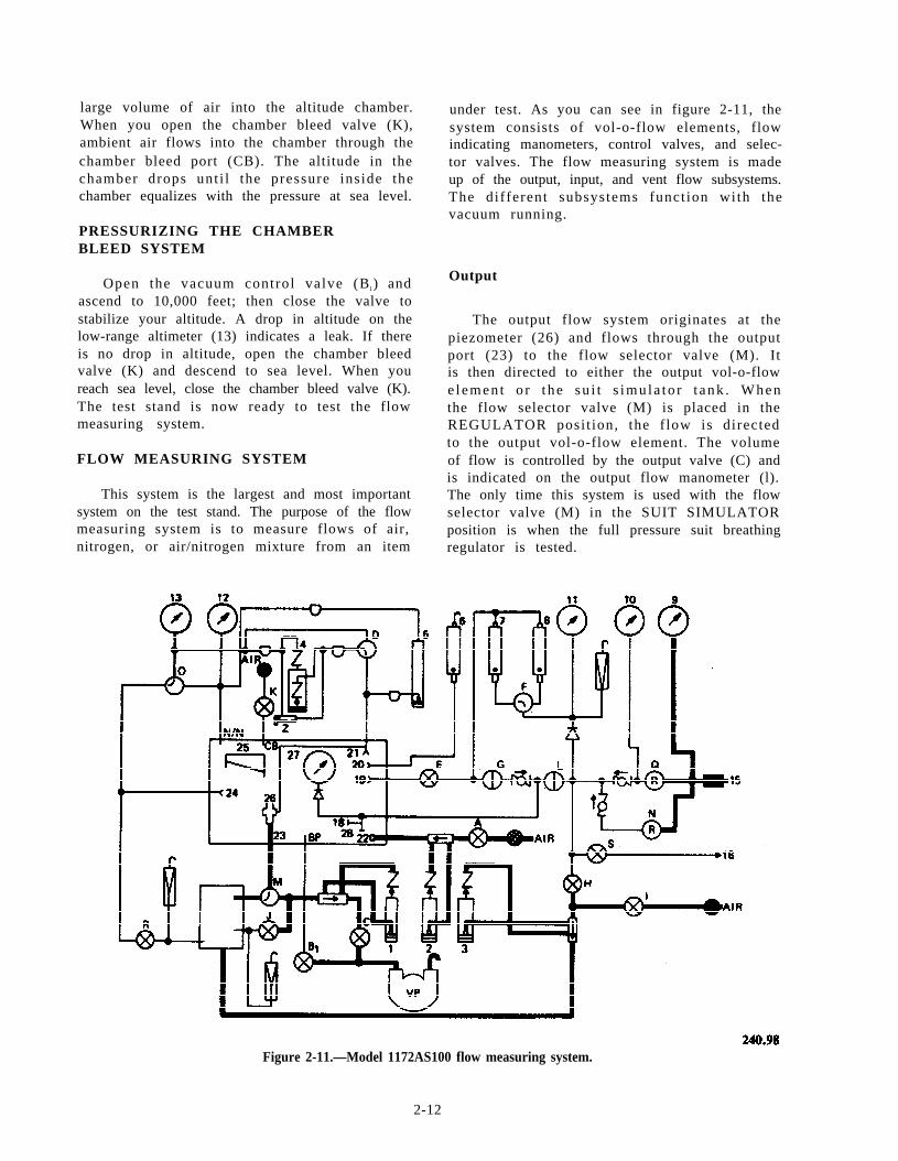
FLOW MEASURING SYSTEM
This system is the largest and most importantsystem on the test stand. The purpose of the flowmeasuring system is to measure flows of air,nitrogen, or air/nitrogen mixture from an item
under test. As you can see in figure 2-11, thesystem consists of vol-o-flow elements, flowindicating manometers, control valves, and selec-tor valves. The flow measuring system is madeup of the output, input, and vent flow subsystems.The different subsystems funct ion with thevacuum running.
Output
The output flow system originates at thepiezometer (26) and flows through the outputport (23) to the flow selector valve (M). Itis then directed to either the output vol-o-flowe lemen t o r t he su i t s imu la to r t ank . Whenthe flow selector valve (M) is placed in theREGULATOR posi t ion, the f low is directedto the output vol-o-flow element. The volumeof flow is controlled by the output valve (C) andis indicated on the output flow manometer (l).The only time this system is used with the flowselector valve (M) in the SUIT SIMULATORposition is when the full pressure suit breathingregulator is tested.
Figure 2-11.—Model 1172AS100 flow measuring system.
2-12
I n p u t PRESSURIZING THE FLOWMEASURING SYSTEM
The input flow system can only be used withthe chamber at altitude. This system originates atthe air intake on the face of the test stand. Whenthe input valve (A) is opened, ambient air flowsthrough this valve (A) to the input vol-o-flowelement. It then flows through the input flowmanometer (2) to the input port (22) inside thechamber. You can control this flow by openingor closing the input valve (A).
VENT FLOW SYSTEM
The vent flow system can originate at eitherthe vent ambient valve (I) or the vent pressurevalve (H). Normally, the vent pressure valve (H)is used only when the chamber and suit simulatortank are at sea level. The vent ambient valve (I)can only be used at altitude. When the ventambient valve (I) is used, air is admitted throughan intake port in the rear of the test stand. It thenflows through the vent flow vol-o-flow elementand is indicated on the vent flow manometer (3).The air then flows to the suit simulator tank.When the flow selector valve (M) is in the SUITSIMULATOR position, air flows to the outputport (23) inside the chamber and continues to thepiezometer (26). You may also direct air from thesuit simulator tank to the output vol-o-flowelement and the output flow manometer (1) byopening the flutter dampener valve (J). The ventpressure valve (H) is used only with low-pressurenitrogen.
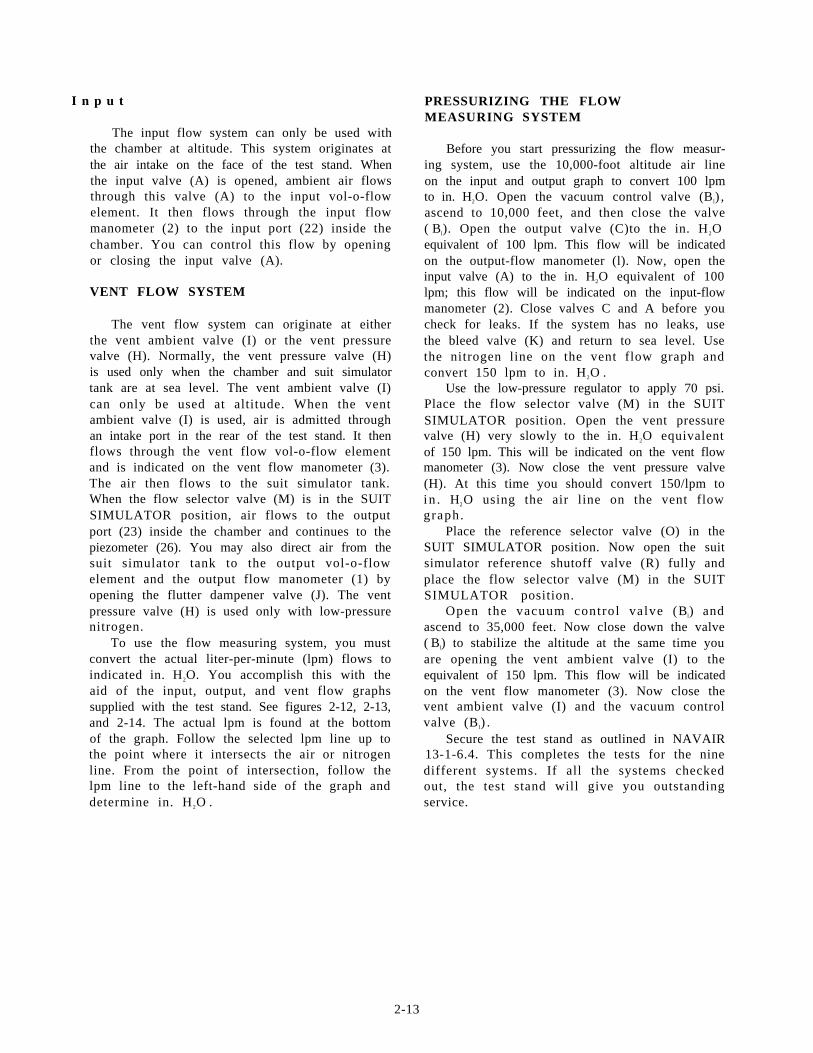
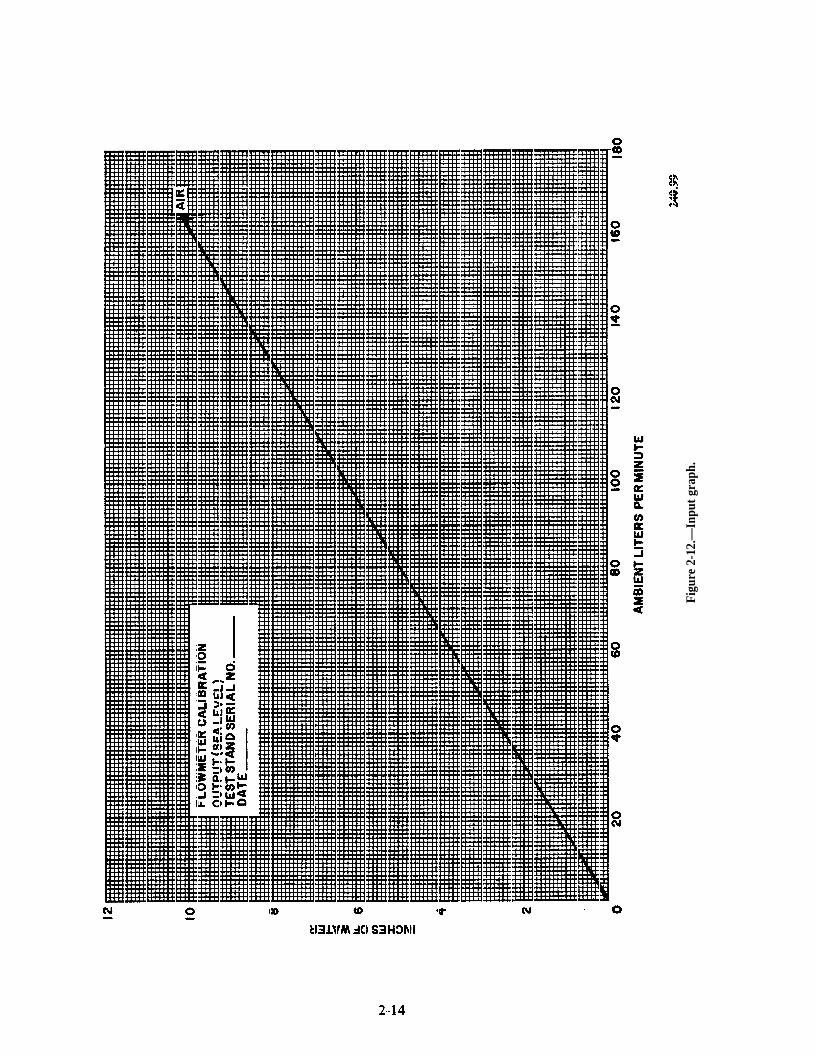
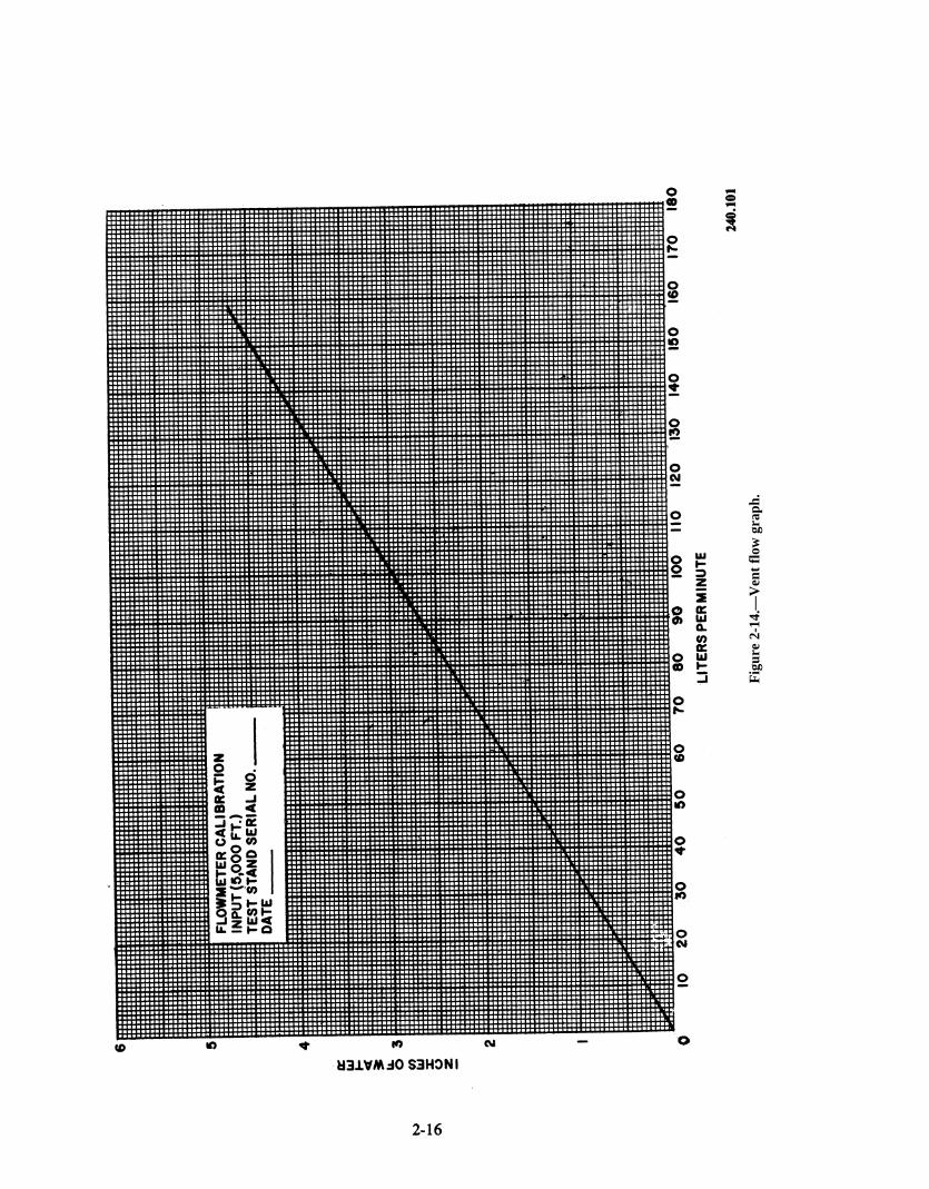
To use the flow measuring system, you mustconvert the actual liter-per-minute (lpm) flows toindicated in. H2O. You accomplish this with theaid of the input, output, and vent flow graphssupplied with the test stand. See figures 2-12, 2-13,and 2-14. The actual lpm is found at the bottomof the graph. Follow the selected lpm line up tothe point where it intersects the air or nitrogenline. From the point of intersection, follow thelpm line to the left-hand side of the graph anddetermine in. H 2O .
Before you start pressurizing the flow measur-ing system, use the 10,000-foot altitude air lineon the input and output graph to convert 100 lpmto in. H2O. Open the vacuum control valve (B l) ,ascend to 10,000 feet, and then close the valve( Bl). Open the output valve (C)to the in. H2Oequivalent of 100 lpm. This flow will be indicatedon the output-flow manometer (l). Now, open theinput valve (A) to the in. H2O equivalent of 100lpm; this flow will be indicated on the input-flowmanometer (2). Close valves C and A before youcheck for leaks. If the system has no leaks, usethe bleed valve (K) and return to sea level. Usethe nitrogen line on the vent flow graph andconvert 150 lpm to in. H2O .
Use the low-pressure regulator to apply 70 psi.Place the flow selector valve (M) in the SUITSIMULATOR position. Open the vent pressurevalve (H) very slowly to the in. H2O equivalentof 150 lpm. This will be indicated on the vent flowmanometer (3). Now close the vent pressure valve(H). At this time you should convert 150/lpm toin . H2O using the air line on the vent flowgraph.
Place the reference selector valve (O) in theSUIT SIMULATOR position. Now open the suitsimulator reference shutoff valve (R) fully andplace the flow selector valve (M) in the SUITSIMULATOR position.
Open the vacuum control valve (Bl) andascend to 35,000 feet. Now close down the valve( Bl) to stabilize the altitude at the same time youare opening the vent ambient valve (I) to theequivalent of 150 lpm. This flow will be indicatedon the vent flow manometer (3). Now close thevent ambient valve (I) and the vacuum controlvalve (B l) .
Secure the test stand as outlined in NAVAIR13-1-6.4. This completes the tests for the ninedifferent systems. If all the systems checkedout, the test stand will give you outstandingservice.
2-13
Pag
e 2-
14.
Figu
re 2
-12.
—In
put g
raph
.
Figure 2-13.
2-15
Pag
e 2-
16.
Fig
ure
2-14
.—V
ent
flow
gra
ph.
CHAPTER 3
CARBON DIOXIDE TRANSFER EQUIPMENT
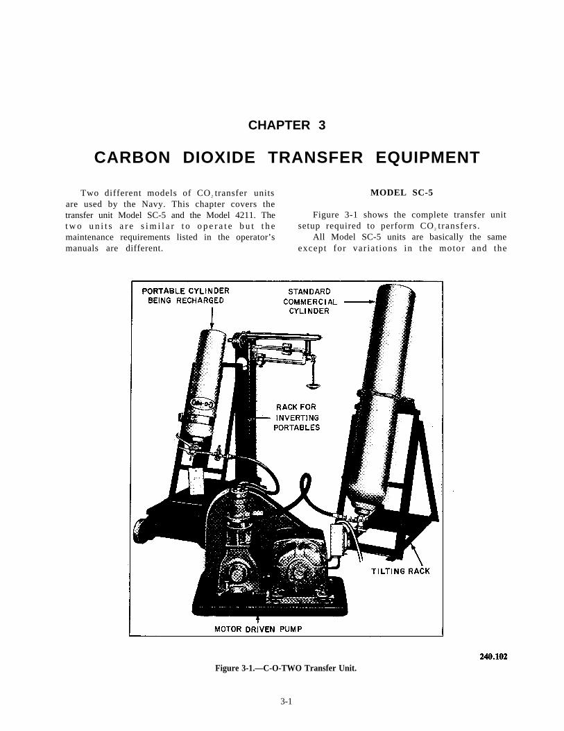
Two different models of CO 2 transfer units MODEL SC-5are used by the Navy. This chapter covers thetransfer unit Model SC-5 and the Model 4211. The Figure 3-1 shows the complete transfer unitt w o u n i t s a r e s i m i l a r t o o p e r a t e b u t t h e setup required to perform CO 2 t ransfers .maintenance requirements listed in the operator’s All Model SC-5 units are basically the samemanuals are different. except for var ia t ions in the motor and the
Figure 3-1.—C-O-TWO Transfer Unit.
3-1
starter arrangements. This model was previouslymanufacturered by two companies, the C-O-TwoFire Equipment and the Norris Fire and SafetyEquipment .
The SC-5 motor is mounted on a sliding,adjustable base so that its position maybe alteredto take up any slack that may develop in the drivebelt.
The SC-5 pump is a single-cylinder design witha working pressure of approximately 3500 poundsper square inch. This unit has the capability oft ransferr ing approximately 80 percent or 38pounds of carbon dioxide from a fully charged50-pound supply cylinder. .
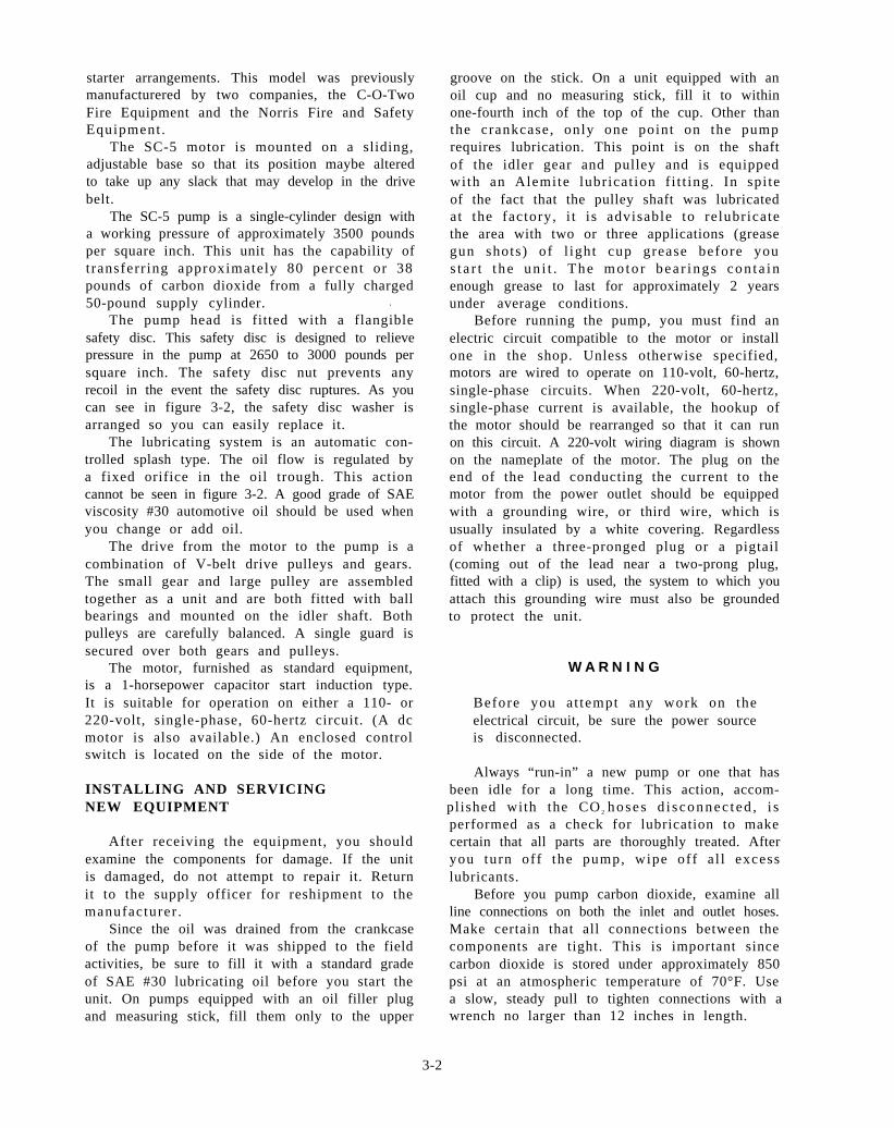
The pump head is fitted with a flangiblesafety disc. This safety disc is designed to relievepressure in the pump at 2650 to 3000 pounds persquare inch. The safety disc nut prevents anyrecoil in the event the safety disc ruptures. As youcan see in figure 3-2, the safety disc washer isarranged so you can easily replace it.
The lubricating system is an automatic con-trolled splash type. The oil flow is regulated bya fixed orifice in the oil trough. This actioncannot be seen in figure 3-2. A good grade of SAEviscosity #30 automotive oil should be used whenyou change or add oil.
The drive from the motor to the pump is acombination of V-belt drive pulleys and gears.The small gear and large pulley are assembledtogether as a unit and are both fitted with ballbearings and mounted on the idler shaft. Bothpulleys are carefully balanced. A single guard issecured over both gears and pulleys.
The motor, furnished as standard equipment,is a 1-horsepower capacitor start induction type.It is suitable for operation on either a 110- or220-volt, single-phase, 60-hertz circuit. (A dcmotor is also available.) An enclosed controlswitch is located on the side of the motor.
INSTALLING AND SERVICINGNEW EQUIPMENT
After receiving the equipment, you shouldexamine the components for damage. If the unitis damaged, do not attempt to repair it. Returnit to the supply officer for reshipment to themanufacturer .
Since the oil was drained from the crankcaseof the pump before it was shipped to the fieldactivities, be sure to fill it with a standard gradeof SAE #30 lubricating oil before you start theunit. On pumps equipped with an oil filler plugand measuring stick, fill them only to the upper
groove on the stick. On a unit equipped with anoil cup and no measuring stick, fill it to withinone-fourth inch of the top of the cup. Other thanthe crankcase, only one point on the pumprequires lubrication. This point is on the shaftof the idler gear and pulley and is equippedwith an Alemite lubricat ion f i t t ing. In spi teof the fact that the pulley shaft was lubricatedat the factory, i t is advisable to relubricatethe area with two or three applications (greasegun shots) of l ight cup grease before yous t a r t t he un i t . The mo to r bea r ings con t a inenough grease to last for approximately 2 yearsunder average conditions.
Before running the pump, you must find anelectric circuit compatible to the motor or installone in the shop. Unless otherwise specified,motors are wired to operate on 110-volt, 60-hertz,single-phase circuits. When 220-volt, 60-hertz,single-phase current is available, the hookup ofthe motor should be rearranged so that it can runon this circuit. A 220-volt wiring diagram is shownon the nameplate of the motor. The plug on theend of the lead conducting the current to themotor from the power outlet should be equippedwith a grounding wire, or third wire, which isusually insulated by a white covering. Regardlessof whether a three-pronged plug or a pigtail(coming out of the lead near a two-prong plug,fitted with a clip) is used, the system to which youattach this grounding wire must also be groundedto protect the unit.
W A R N I N G
Before you at tempt any work on theelectrical circuit, be sure the power sourceis disconnected.
Always “run-in” a new pump or one that hasbeen idle for a long time. This action, accom-plished with the CO 2 hoses d i s connec t ed , i sperformed as a check for lubrication to makecertain that all parts are thoroughly treated. Afteryou turn off the pump, wipe off a l l excesslubricants.
Before you pump carbon dioxide, examine allline connections on both the inlet and outlet hoses.Make certain that all connections between thecomponents are tight. This is important sincecarbon dioxide is stored under approximately 850psi at an atmospheric temperature of 70°F. Usea slow, steady pull to tighten connections with awrench no larger than 12 inches in length.
3-2
Pag
e 3-
3.
Figu
re 3
-2.—
C-O
-TW
O T
rans
fer
Uni
t D
etai
l.
The transfer unit pumps carbon dioxide in itsliquid phase only. This is true of all CO2 transferuni ts . The amount of l iquid carbon dioxidecontained in a fully charged cylinder varies withthe p r e s su re and t empe ra tu r e ; t he r e fo re , astandard 50-pound cylinder contains approx-imately 38 pounds of carbon dioxide in its liquidphase and approximately 12 pounds in its gaseousphase at an atmospheric temperature of 70°F.Therefore, the cooler the supply cylinder and thecylinder being recharged, the more efficient theoperation of the transfer unit. Consequently, allcylinders should be kept in the coolest locationpossible. Conversely, the time required to chargean empty cylinder increases with increasedtemperature of the cylinder. When recharging asmaller cylinder, we found that if you invert thecylinder during the recharging period, it remainscooler and fills faster than it would if placed inan upright position. Larger cylinders should beplaced horizontally on the scale when they arebeing recharged.
After all the liquid carbon dioxide is trans-ferred from the supply cylinder, which is approx-imately 80 percent of the net contents, the transferof CO 2 to the cylinder being recharged stops.After this, another fully charged supply cylindermust be used to finish recharging the cylinder toi ts ful l-rated capacity. The majori ty of gasremaining in the other supply cylinder can beused when you recharge another empty cylinder.The gas transfers itself under its own pressure untilthe pressure in both cylinders is equal. Thismethod is called cascading. Through this method,the most economical use of the contents of thesupply cylinder is made.
To prevent expansion of carbon dioxide in thesupply hose, and consequently blocking the hosewi th CO2 “ s n o w , ” you should use a valve withan outlet opening of at least one-eighth inch indiameter-preferably three-sixteenths of an inch.Standard supply cylinders in 50-pound sizes areobtainable with or without a syphon tube. Whenyou order cylinders, specify the ones with asyphon tube. Those without syphons must beinverted during the transfer process.
MAINTENANCE
Main t enance mus t be pe r fo rmed on a l lcarbon dioxide equipment on a periodic basis.These maintenance procedures are discussed in thefollowing paragraphs.
Once Every Month
Check the level of the oil in the crankcase. Seethat it is within one-fourth inch of the top of thefilling cup or to the upper groove in the measur-ing stick if the unit is so equipped. If you mustadd any oil, use only a good grade of SAEviscosity #30 automotive crankcase lubricatingoil.
Once Every 6 Months
Lubr i ca t e t he i d l e r sha f t . Th i s sha f t i sequipped with a fitting of the variety that iscommonly used in the automotive field. Two orthree “ sho t s” o f l i gh t cup g rea se w i l l beample.
Lubricate the gear teeth with a thin coatingof light cup grease.
With a small piece of wood, or preferably asmall brush, apply a light coating of Vaseline tothe piston rod. To do this, dip the brush inVaseline, hold the brush against the piston rod,and manually rotate the gears until the piston rodi s comple t e ly and t ho rough ly coa t ed w i thVaseline.
If necessary, tighten the packing at the pistonstem. A special wrench is provided for thispurpose. Do not tighten excessively. Because ofthe design of the packing, it must only fit snuglyto hold tightly.
Keep the motor commutator clean and main-tain a clean surface. Under normal operatingconditions, the commutator will require onlyoccasional cleaning with a dry piece of nonlintingcloth. Do not lubricate the commutator.
Every 12 Months
The oil should be drained from the crankcaseand replaced with clean, fresh oil of the qualityand viscosity specified.
Once Every 2 Years
The bearing housings of the electric motorshould be removed and lubricated. To do this,disassemble the bearing housing. Then clean theinside of the housings, the plates or caps, and thebearings with carbon tetrachloride. Wipe off allgrease and reassemble all parts except the outercaps or plates. Apply the new grease, either froma tube or by hand, over and between each ball.When you do this , do not apply more thanone-half of an ounce of grease at each bearing.
3-4
Too much grease may cause excessive bearingtemperature and cause the grease to leak out ofthe housing to the windings.
Piston Rod Packing
Piston rod packing should be replaced onceevery 2 years.
To replace the piston rod packing, use thefollowing steps:
1. Remove the six bolts on top of the cylinderhead. Remove the cylinder head.
2. Loosen the hex nut (figure 3-2) at thebottom of the piston rod.
3. Remove the three bol ts that hold thecylinder body to the crosshead guide unit.
4. Raise the cylinder body and unscrew thepiston rod from the crosshead so that it clears thebase.
5 . The pis ton rod packing is now in aposition to be replaced. Remove the locknut fromthe piston rod and then remove the piston rodpacking nut.
6. When you replace the flanged-type pack-ing, remember that the packing nut serves onlyto hold the packing in place. Tightening the nutexcessively will not increase its efficiency; thepacking nut should not be forced down tightenough to damage the packing flange.
7. After you replace the packing and packingnut, mount the cylinder body on the crossheadguide. Make certain that the locknut is replacedon the piston rod before you screw it into thecrosshead.
8. Screw the piston rod into the crossheaduntil the top edge of the piston packing is flushwith the top of the cylinder body, with thecrosshead in the uppermost position (figure 3-2).To check this adjustment, rock the crank backand forth; then tighten the locknut at the bottomof the piston rod.
9. Replace the piston head and tighten all themounting bolts.
WALTER KIDDE TRANSFER UNIT
The Walter Kidde unit , l ike the SC-5 isdesigned and manufactured expressly for thepurpose of transferring carbon dioxide in itsliquid form from one cylinder to another. The unitis supplied complete with the necessary adapters,recharging valves, safety discs and bushings, nuts,bolts, and washers needed to make connections
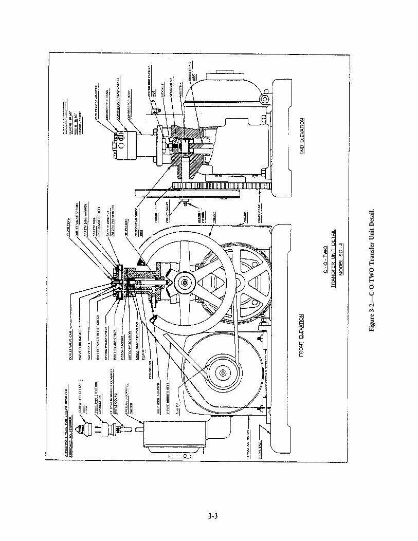
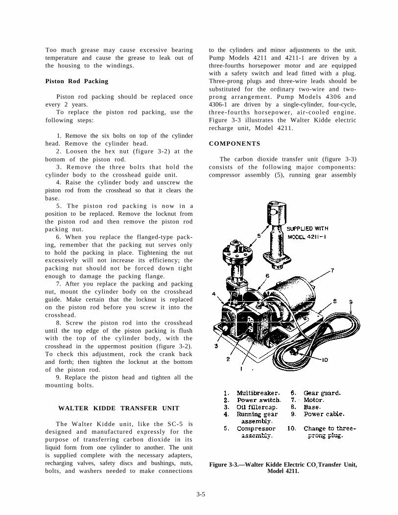
to the cylinders and minor adjustments to the unit.Pump Models 4211 and 4211-1 are driven by athree-fourths horsepower motor and are equippedwith a safety switch and lead fitted with a plug.Three-prong plugs and three-wire leads should besubstituted for the ordinary two-wire and two-prong arrangement . Pump Models 4306 and4306-1 are driven by a single-cylinder, four-cycle,three-fourths horsepower, a i r -cooled engine.Figure 3-3 illustrates the Walter Kidde electricrecharge unit, Model 4211.
COMPONENTS
The carbon dioxide transfer unit (figure 3-3)consists of the following major components:compressor assembly (5), running gear assembly
Figure 3-3.—Walter Kidde Electric CO2 Transfer Unit,Model 4211.
3-5
(4), motor (7), multibreaker (l), power cable (9),and base (8). The only difference between themodels lies in the type of compressor supplied;however, the compressors are interchangeablebetween the models. A spare parts kit, rechargingtransfer fittings, and charging fittings are used inconjunction with the units.
Motor
The repulsion start induction single-phasemotor, shown in figure 3-3, is a 115- to 230-volt,60-cycle , three-fourths horsepower uni t . I toperates at 1750 rpm and draws 9.8 amperes at115 volts. This type of motor supplies very highstarting torque with a very low starting current.In s tar t ing, the motor has repulsion motorcharacteristics; but at running speeds, it functionsas an induction motor since the motor windingsare automatically short-circuited and the brushesa r e l i f t ed f rom the commuta to r when t heoperating speed is approached.
Multibreaker
The thermal, magnetic multibreaker, shownin figure 3-3, is a two-pole, 115-volt ac, 20-ampereunit installed to protect the power circuit fromoverloads. In addi t ion, i t acts as a manualON/OFF switch for the operation of the transferunit. If the multibreaker trips because of a poweroverload, you may reset it by placing the switchfirst to OFF and then to ON.
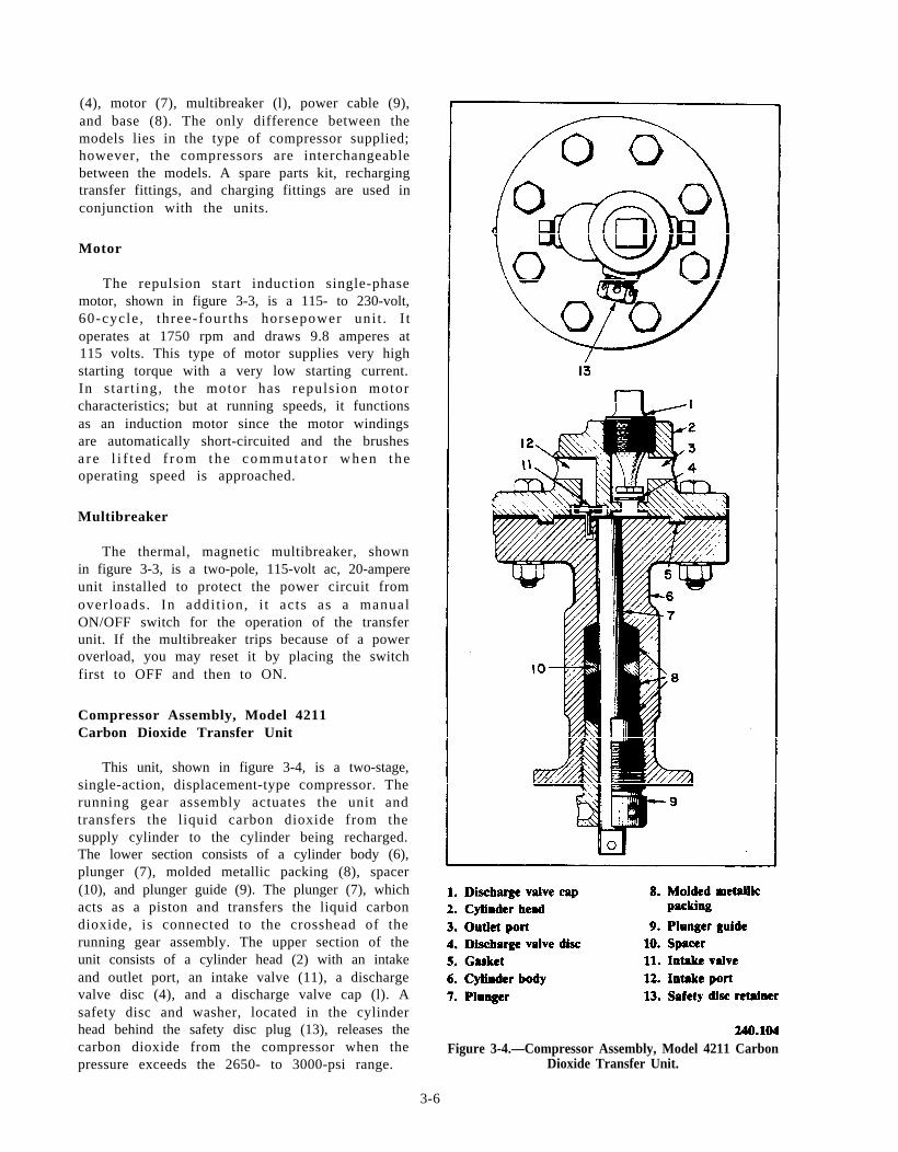
Compressor Assembly, Model 4211Carbon Dioxide Transfer Unit
This unit, shown in figure 3-4, is a two-stage,single-action, displacement-type compressor. Therunning gear assembly actuates the unit andtransfers the liquid carbon dioxide from thesupply cylinder to the cylinder being recharged.The lower section consists of a cylinder body (6),plunger (7), molded metallic packing (8), spacer(10), and plunger guide (9). The plunger (7), whichacts as a piston and transfers the liquid carbondioxide, is connected to the crosshead of therunning gear assembly. The upper section of theunit consists of a cylinder head (2) with an intakeand outlet port, an intake valve (11), a dischargevalve disc (4), and a discharge valve cap (l). Asafety disc and washer, located in the cylinderhead behind the safety disc plug (13), releases thecarbon dioxide from the compressor when thepressure exceeds the 2650- to 3000-psi range.
Figure 3-4.—Compressor Assembly, Model 4211 CarbonDioxide Transfer Unit.
3-6
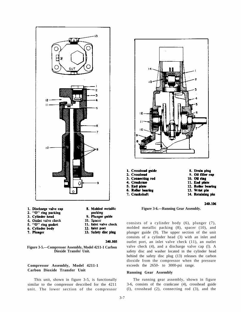
Figure 3-5.—Compressor Assembly, Model 4211-1 CarbonDioxide Transfer Unit.
Compressor Assembly, Model 4211-1Carbon Dioxide Transfer Unit
This unit, shown in figure 3-5, is functionallysimilar to the compressor described for the 4211unit . The lower sect ion of the compressor
Figure 3-6.—Running Gear Assembly.
consists of a cylinder body (6), plunger (7),molded metallic packing (8), spacer (10), andplunger guide (9). The upper section of the unitconsists of a cylinder head (3) with an inlet andoutlet port, an inlet valve check (11), an outletvalve check (4), and a discharge valve cap (l). Asafety disc and washer located in the cylinder headbehind the safety disc plug (13) releases the carbondioxide from the compressor when the pressureexceeds the 2650- to 3000-psi range.
Running Gear Assembly
The running gear assembly, shown in figure3-6, consists of the crankcase (4), crosshead guide(l), crosshead (2), connecting rod (3), and the
3-7
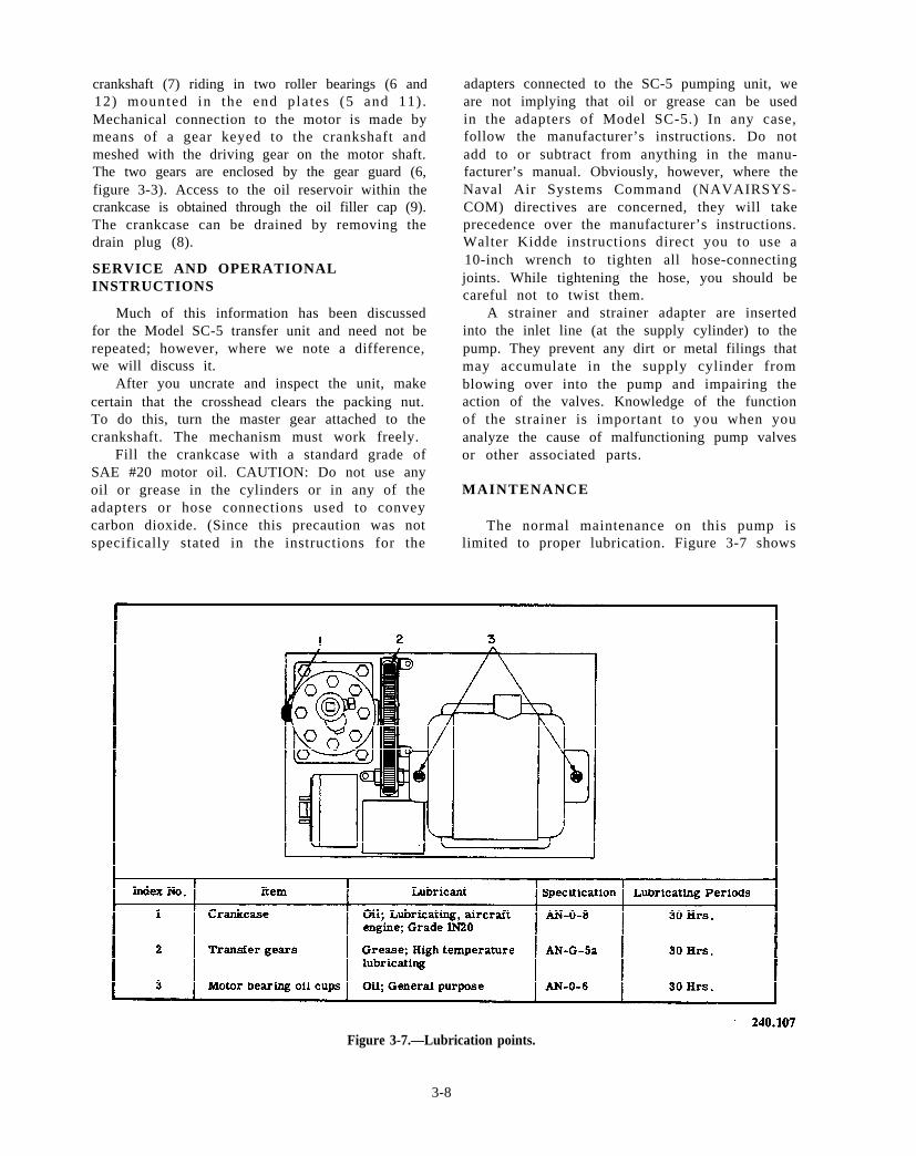
crankshaft (7) riding in two roller bearings (6 and12) mounted in the end pla tes (5 and 11) .Mechanical connection to the motor is made bymeans of a gear keyed to the crankshaft andmeshed with the driving gear on the motor shaft.The two gears are enclosed by the gear guard (6,figure 3-3). Access to the oil reservoir within thecrankcase is obtained through the oil filler cap (9).The crankcase can be drained by removing thedrain plug (8).
SERVICE AND OPERATIONALINSTRUCTIONS
Much of this information has been discussedfor the Model SC-5 transfer unit and need not berepeated; however, where we note a difference,we will discuss it.
adapters connected to the SC-5 pumping unit, weare not implying that oil or grease can be usedin the adapters of Model SC-5.) In any case,follow the manufacturer’s instructions. Do notadd to or subtract from anything in the manu-facturer’s manual. Obviously, however, where theNaval Air Systems Command (NAVAIRSYS-COM) directives are concerned, they will takeprecedence over the manufacturer’s instructions.Walter Kidde instructions direct you to use a10-inch wrench to tighten all hose-connectingjoints. While tightening the hose, you should becareful not to twist them.
A strainer and strainer adapter are insertedinto the inlet line (at the supply cylinder) to thepump. They prevent any dirt or metal filings thatmay accumulate in the supply cylinder from
After you uncrate and inspect the unit, make blowing over into the pump and impairing thecertain that the crosshead clears the packing nut. action of the valves. Knowledge of the functionTo do this, turn the master gear attached to the of the strainer is important to you when youcrankshaft. The mechanism must work freely. analyze the cause of malfunctioning pump valves
Fill the crankcase with a standard grade of or other associated parts.SAE #20 motor oil. CAUTION: Do not use anyoil or grease in the cylinders or in any of the MAINTENANCEadapters or hose connections used to conveycarbon dioxide. (Since this precaution was not The normal maintenance on this pump isspecifically stated in the instructions for the limited to proper lubrication. Figure 3-7 shows
Figure 3-7.—Lubrication points.
3-8
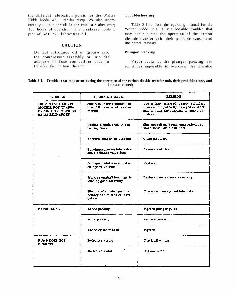
the different lubrication points for the Walter TroubleshootingKidde Model 4211 transfer pump. We also recom-mend you drain the oil in the crankcase after every Table 3-1 is from the operating manual for the150 hours of operation. The crankcase holds 1 Walter Kidde unit. It lists possible troubles thatpint of SAE #20 lubricating oil. may occur during the operation of the carbon
CAUTION
die-tide transfer unit, their probable cause,indicated remedy.
Do no t i n t roduce o i l o r g r ea se i n to Plunger Packingthe compressor assembly or into theadapters or hose connect ions used to Vapor leaks at the plunger packing
a n d
aretransfer the carbon dioxide. sometimes impossible to overcome. An invisible
Table 3-1.—Troubles that may occur during the operation of the carbon dioxide transfer unit, their probable cause, andindicated remedy
3-9
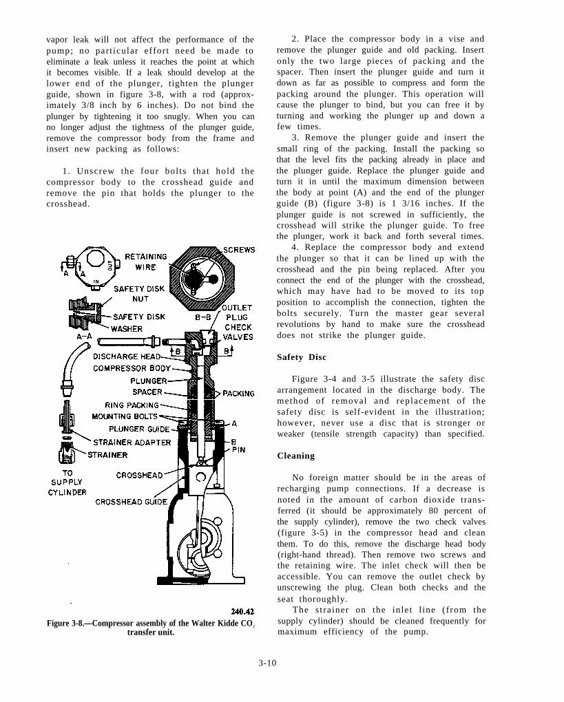
vapor leak will not affect the performance of thepump; no part icular effort need be made toeliminate a leak unless it reaches the point at whichit becomes visible. If a leak should develop at thelower end of the plunger, tighten the plungerguide, shown in figure 3-8, with a rod (approx-imately 3/8 inch by 6 inches). Do not bind theplunger by tightening it too snugly. When you canno longer adjust the tightness of the plunger guide,remove the compressor body from the frame andinsert new packing as follows:
1. Unscrew the four bol ts that hold thecompressor body to the crosshead guide andremove the pin that holds the plunger to thecrosshead.
Figure 3-8.—Compressor assembly of the Walter Kidde CO2
transfer unit.
2. Place the compressor body in a vise andremove the plunger guide and old packing. Insertonly the two large pieces of packing and thespacer. Then insert the plunger guide and turn itdown as far as possible to compress and form thepacking around the plunger. This operation willcause the plunger to bind, but you can free it byturning and working the plunger up and down afew times.
3. Remove the plunger guide and insert thesmall ring of the packing. Install the packing sothat the level fits the packing already in place andthe plunger guide. Replace the plunger guide andturn it in until the maximum dimension betweenthe body at point (A) and the end of the plungerguide (B) (figure 3-8) is 1 3/16 inches. If theplunger guide is not screwed in sufficiently, thecrosshead will strike the plunger guide. To freethe plunger, work it back and forth several times.
4. Replace the compressor body and extendthe plunger so that it can be lined up with thecrosshead and the pin being replaced. After youconnect the end of the plunger with the crosshead,which may have had to be moved to its topposition to accomplish the connection, tighten thebolts securely. Turn the master gear severalrevolutions by hand to make sure the crossheaddoes not strike the plunger guide.
Safety Disc
Figure 3-4 and 3-5 illustrate the safety discarrangement located in the discharge body. Themethod of removal and replacement of thesafety disc is self-evident in the illustration;however, never use a disc that is stronger orweaker (tensile strength capacity) than specified.
Cleaning
No foreign matter should be in the areas ofrecharging pump connections. If a decrease isnoted in the amount of carbon dioxide trans-ferred (it should be approximately 80 percent ofthe supply cylinder), remove the two check valves(figure 3-5) in the compressor head and cleanthem. To do this, remove the discharge head body(right-hand thread). Then remove two screws andthe retaining wire. The inlet check will then beaccessible. You can remove the outlet check byunscrewing the plug. Clean both checks and theseat thoroughly.
The s trainer on the inlet l ine (from thesupply cylinder) should be cleaned frequently formaximum efficiency of the pump.
3-10
NOTE: Remember you are dealing with high--pressure gas. Before attempting to recharge anyextinguisher, you should become thoroughlyacquainted with the recharging pump and themethods of recharging. Carefully read the instruc-tions that pertain to the recharge pump and besure all connections are tight at all times.
C O2 CYLINDERS AND SAFETY DISC
Carbon dioxide cylinders should be chargedwith “bone-dry” carbon dioxide. Extreme caremust be taken in the charging, weighing, sealing,and testing of cylinders.
The safety discs of the cylinders are paintedvarious colors to identify the pressure at whichthey will rupture. The correct color disc must beused in every case. All cylinders are manufacturedin accordance with the requirements of theInterstate Commerce Commission (ICC) as setd o w n b y t h e B u r e a u o f E x p l o s i v e s . T h e s erequirements specify that the cylinder be testedto five-thirds of its normal working pressure andthat the normal working pressure be stamped onthe cylinder immediately following the lettersICC3A. We refer to this procedure as hydrostatictesting. Common cylinder stampings and thecorresponding test pressures are as follows:
Cylinder Test Color ofStamping Pressure Permissible Disc
ICC 3 3000 psi WhiteICC 3A 1800 3000 psi WhiteICC 3A 2015 3360 psi WhiteICC 3A 2205 3680 psi White or redICC 3A 2300 3840 psi White or red
You should never use a disc in a valve whereit would be working in connection with a differenttype of safety disc retainer. Never trim a safetydisc to fit a valve other than the one for whichit was intended.
You will find similar markings on the shoulderof every cylinder.
ICC 3A 1800 W. K. & Co.221974 10-84
H
An explanation of these marks follows:
ICC 3A 1800 signifies the specific ICC testprocedure followed. The number 1800 indicatesthe service pressure.
221974 is the cylinder serial number. Somecylinders have one or two letters as part of theserial number. (The U.S. Navy also assigns oneof their numbers to all cylinders they purchase.This number has the letters USN accompanyingit.) The letter H in a shield is the designation markof the accredited ICC inspecting laboratory thatsupervises our tests.
The letters W. K. & Co designate the manufac-turer of the cylinder.
The numbers 10-84 mean that the cylinder wastested in October of 1984 and that its next testwill be October 1989.
Before any cylinder is recharged, the date mustbe checked; if more than 5 years has elapsed, thecylinder must be retested hydrostatically. Thedate of the retest is then stamped on the cylinderdirectly under the original date. This new date isthe one against which future checks should bemade.
Remember you are dealing with high-pressuregas. Before recharging any cylinder, you mustbecome thoroughly famil iar with the properprocedure for recharging.
When you handle or ship cyl inders , theshipping cap should always be assembled on thecylinder. On cylinders where this is not possible,the cylinder should be carefully crated.
Be thoroughly familiar with these proceduresbefore you attempt to recharge any cylinder. Afew minutes spent on becoming familiar with theprocedure may prevent an accident involvinginjury to personnel or damage to equipment.
WINTERIZING CARBONDIOXIDE CYLINDERS
The PR is not normally tasked with theresponsibility of recharging fire extinguishers andengine f i re bot t les . H o w e v e r , y o u m a y b eassigned to an AIMD that supports aircraft thatrequire winterizing of CO2 cyl inders .
All carbon dioxide portable fire extinguishersinstal led in aircraft and al l aircraft carbondioxide built-in engine fire extinguishers areserviced to operate throughout the temperaturerange of –65°F to 160°F. The extinguishers aresupercharged with the addition of 200 psi of dry,oil-free nitrogen. This servicing of extinguishersis done in connection with the U.S. Air Forcewinterization program. Extinguishers charged tomeet this winterization requirement are identifiedby a yellow dot, three-fourths of an inch indiameter or larger, on opposite sides of thecylinder. Extinguishers so marked are winterized
3-11

Figure 3-9.—Disassembly of Inflation Valve Safety Disc Assembly.
3-12
by the int roduct ion of ni t rogen at 200 psiand then the addition of a proper charge ofcarbon dioxide.
The addition of nitrogen in carbon dioxidecyl inders provides addi t ional pressure. Thispressure expels the carbon dioxide at extremelycold temperatures (below 0°F) at a much higherrate than would the pressure of the carbondioxide itself. Winterized cylinders have a carbondioxide charge less than rated capacity. As a resultthe total pressure is lower at high temperaturesthan with rated charge, even though nitrogen hasbeen added. Thus winterized cylinders can besubjected to 160°F without the safety discrupturing.
REPLACING SAFETY DISCS ANDWASHERS ON INFLATION VALVES
If you are not familiar with the flotationequipment, replacing safety discs and washers onthe various CO2 cylinders can be very difficult.You will need some special tools to replace the.safety disc and washers on inf la t ion valvea s s e m b l i e s A - 1 2 8 / 8 1 7 4 4 4 , M I L - V - 8 1 7 2 2(Flu-6/P), and MIL-V-25492 (figure 3-9). Youwill require a torque wrench, a five-sixteenthinch socket, and apiece of hex stock 5/16 x 2
inches long. O n c e y o u h a v e t h e s e t o o l s ,changing the safety disc will be a simple process.
W A R N I N G
Before you perform any work on inflationva lves , e n s u r e t h a t C O2 i n f l a t i o nassemblies are completely discharged. Donot remove the valve or valve safety discp l u g f r o m a c h a r g e d C O2 a s s e m b l y .Insert the 5/16- x 2-inch stock into thedisc plug and remove the safety discplug. Then insert the safety disc and washeras shown in figure 3-9. To replace theseitems, simply reinstall them into the infla-t ion valve. Remember to instal l newwashers and safety discs. Use a torquewrench to make the following torque valveadjustments .
Valve Torque (lb)
A-18 29MIL-V-81722 (Flu-6/P) 15-17MIL-V-25492 28-35(Hood valve)
NOTE: While you are tightening thedisc plug, align the insert with the plug.
safety
3-13

SEWING
CHAPTER 4
MACHINE REPAIR
The Aircrew Survival Equipmentman (PR) iscalled upon to perform an enormous amount ofrepair work on parachutes and survival equipmentin all types of maintenance activities. Althoughlower rated personnel perform much of this work,the task of maintaining the sewing machines intop running condition falls to the senior PRs.Qualified sewing machine operators may assist inthis work under supervision; however, determin-ing the causes of malfunctions, making majoradjustments, and replacing parts are the respon-sibilities of the first class and chief petty officer.
This chapter explains the rotory-hook (111 W155) sewing machine and the oscillating-shuttle(31-15) sewing machine. We gave you an overviewof these two types of sewing machines in chapter3 of the Aircrew Survival Equipmentman 3 & 2,volume 1; however, as a senior PR, you need morespecific information on the basic structure of thesetwo sewing machines. With the informationavailable, you can repair any of these types ofmachines the Navy uses. We know it is verydifficult to find information on sewing machinerepair; therefore, you should use this chapter asa reference when working on the alternating-presser-foot sewing machine and the s impleoscillating-shuttle sewing machine.
Your shop may have the Consew Model 225,the Juki LU-562, or the Singer Model 111 W 155sewing machine. These three sewing machines areessentially identical, and all specifications andinstructions are the same for all three sewingmachines. For simplicity we will use the Singer111 W 155 as a model for all three sewingmachines.
The oscillating-shuttle, Singer 31-15, sewingmachine is representative of the second type ofsewing machine used by the Navy. The descriptivet e rm osci l lat ing shutt le refers to the actionof the sewing hook (the way it makes a stitchin unison with the needle). The 31-15 is usedfor sewing lightweight fabrics and is ideallysuited for use in the maintenance of aviationsurvival equipment. Although the physical size
of other oscillating-shuttle sewing machines maybe quite different from the 31-15, such as the largeC l a s s 7 m a c h i n e s , t h e i r o p e r a t i o n a n dmaintenance are very similar.
111 W 155 SEWING MACHINE
The 111 W 155 sewing machine is a single-needle, compound-feed sewing machine withalternating presser feet. This sewing machinemakes the standard US 301 lockstitch and sewsmedium-heavy fabrics. It is equipped with avertical-axis rotating hook. This sewing machineis classified as a rotory-type sewing machine andis also equipped with two presser feet; one is avibrating presser foot, and the other one is alifting presser foot. The front (vibrating) presserfoot, the needle, and the feed dogs move inunison. Together they move the cloth away fromthe operator with each completed stitch. The rear(lifting) presser foot holds the fabric in place whilethe vibrating presser foot rises and moves forwardto start the feeding action for another stitch. Thissewing machine is capable of operating at a speedof 3500 stitches per minute (SPM). The stitchregulator provides a range of 3 1/2 to 32 stitchesper inch (SPI).
The 111 W 155 is the same sewing machinein most ways as the 111 W 151, except for itsalternating presser feet, which give the 111W 155 a more posi t ive feeding act ion. The111 W 155 also has a longer s t i tch length(3 1/2 SPI instead of 5 SPI) and a highermaximum presser-foot lift (one-half inch insteadof three-eighths inch). The 111 W 155 is an idealsewing machine to use on medium-heavy fabricssuch as vinyl and canvas.
This RTM will also include disassembly andassembly of the 111 W 155 sewing machine. Tosimplify minor repairs to this sewing machine andthe 31-15 sewing machine, we have placed ourdiscussion of disassembly and assembly to the rearof the chapter.
4-1
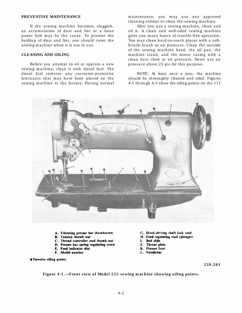
PREVENTIVE MAINTENANCE
If the sewing machine becomes sluggish,an accumulation of dust and lint or a loosepower belt may be the cause. To prevent thebuildup of dust and lint, you should cover thesewing machine when it is not in use.
CLEANING AND OILING
Before you attempt to oil or operate a newsewing machine, clean it with diesel fuel. Thediesel fuel removes any corrosion-protectivelubricants that may have been placed on thesewing machine at the factory. During normal
maintenance, you may use any approvedcleaning solvent to clean the sewing machine.
After you use a sewing machine, clean andoil it. A clean and well-oiled sewing machinegives you many hours of trouble-free operation.You may clean hard-to-reach places with a soft-bristle brush or air pressure. Clean the outsideof the sewing machine head, the oil pan, themachine stand, and the motor casing with aclean dust cloth or air pressure. Never use airpressure above 25 psi for this purpose.
NOTE: At least once a year, the machineshould be thoroughly cleaned and oiled. Figures4-1 through 4-3 show the oiling points on the 111
239.281
Figure 4-1.—Front view of Model 225 sewing machine showing oiling points.
4-2

239.283
Figure 4-2.—Rear view of Model 225 machine showing oiling points.
W 155 sewing machine. Do not use too much oil;usually 1 drop of oil at each oiling point is sufficient.An excessive amount of oil will soil the project beingsewn. We recommend a 10W mineral-base oil. (Useof castor-base oil is no longer required.) If this typeof oil is not available through normal supplychannels, use the mineral oil or Singer Type B or D.
TIMING THE 111 W 155 MACHINE
Timing is the most important step when you areworking on any machine. As you read through thefollowing timing and adjustment sequence, you mayfind that it has changed from steps you are
accustomed to using. This timing and adjustmentsection is presented as if you are taking yourmachine completely apart and reassembling it.
1. Timing the arm shaft with the hook driveshaft
To perform this timing step, you must tilt the sewingmachine back on its hinges. Turn the balance wheeltoward the operator until the thread take-up lever reachesits highest point. You can do this step by placing thefingers of your left hand on top of the thread take-uplever and turning the balance wheel with your right hand.You should be able to feel the high point of
4-3
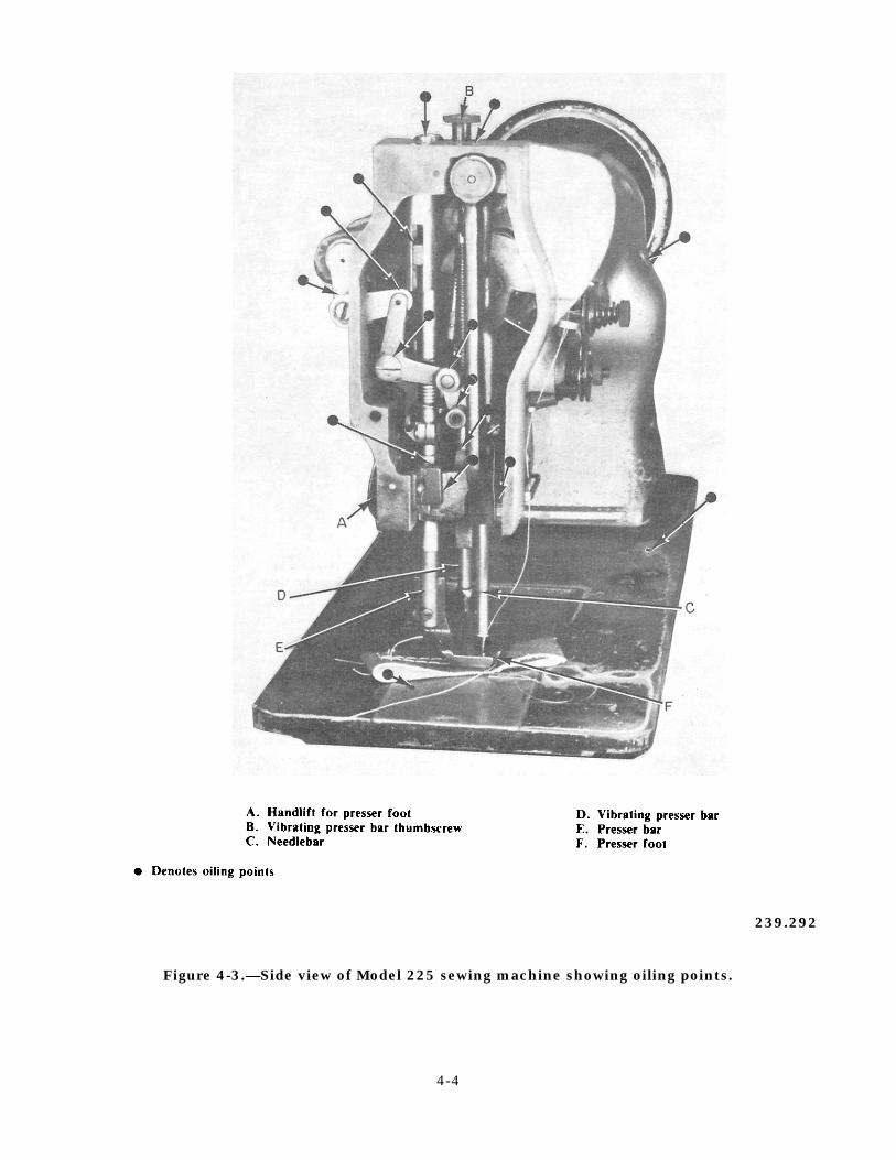
239.292
Figure 4-3.—Side view of Model 225 sewing machine showing oiling points.
4-4
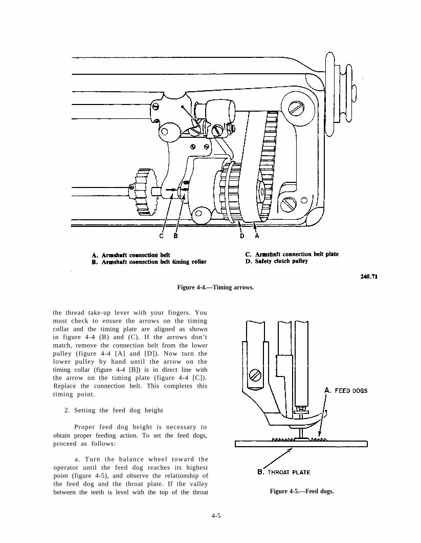
Figure 4-4.—Timing arrows.
the thread take-up lever with your fingers. Youmust check to ensure the arrows on the timingcollar and the timing plate are aligned as shownin figure 4-4 (B) and (C). If the arrows don’tmatch, remove the connection belt from the lowerpulley (figure 4-4 [A] and [D]). Now turn thelower pulley by hand until the arrow on thetiming collar (figure 4-4 [B]) is in direct line withthe arrow on the timing plate (figure 4-4 [C]).Replace the connection belt. This completes thistiming point.
2. Setting the feed dog height
Proper feed dog height is necessary toobtain proper feeding action. To set the feed dogs,proceed as follows:
a . Turn the balance wheel toward theoperator until the feed dog reaches its highestpoint (figure 4-5), and observe the relationship ofthe feed dog and the throat plate. If the valleybetween the teeth is level with the top of the throat Figure 4-5.—Feed dogs.
4-5
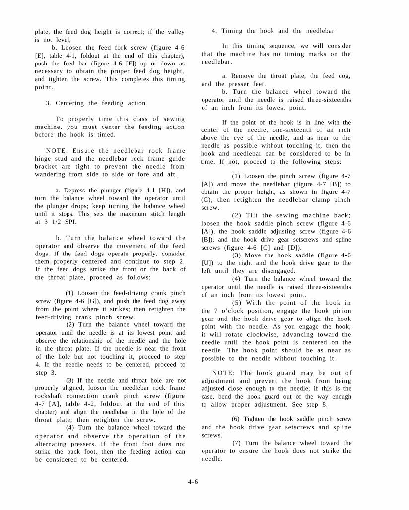
plate, the feed dog height is correct; if the valleyis not level,
b. Loosen the feed fork screw (figure 4-6[E], table 4-1, foldout at the end of this chapter),push the feed bar (figure 4-6 [F]) up or down asnecessary to obtain the proper feed dog height,and tighten the screw. This completes this timingpoint .
3. Centering the feeding action
To properly time this class of sewingmachine, you must center the feeding actionbefore the hook is timed.
NOTE: Ensure the needlebar rock framehinge stud and the needlebar rock frame guidebracket are tight to prevent the needle fromwandering from side to side or fore and aft.
a. Depress the plunger (figure 4-1 [H]), andturn the balance wheel toward the operator untilthe plunger drops; keep turning the balance wheeluntil it stops. This sets the maximum stitch lengthat 3 1/2 SPI.
b. Turn the balance wheel toward theoperator and observe the movement of the feeddogs. If the feed dogs operate properly, considerthem properly centered and continue to step 2.If the feed dogs strike the front or the back ofthe throat plate, proceed as follows:
(1) Loosen the feed-driving crank pinchscrew (figure 4-6 [G]), and push the feed dog awayfrom the point where it strikes; then retighten thefeed-driving crank pinch screw.
(2) Turn the balance wheel toward theoperator until the needle is at its lowest point andobserve the relationship of the needle and the holein the throat plate. If the needle is near the frontof the hole but not touching it, proceed to step4. If the needle needs to be centered, proceed tostep 3.
(3) If the needle and throat hole are notproperly aligned, loosen the needlebar rock framerockshaft connection crank pinch screw (figure4-7 [A], table 4-2, foldout at the end of thischapter) and align the needlebar in the hole of thethroat plate; then retighten the screw.
(4) Turn the balance wheel toward theo p e r a t o r a n d o b s e r v e t h e o p e r a t i o n o f t h ealternating pressers. If the front foot does notstrike the back foot, then the feeding action canbe considered to be centered.
4. Timing the hook and the needlebar
In this timing sequence, we will considerthat the machine has no timing marks on theneedlebar.
a. Remove the throat plate, the feed dog,and the presser feet.
b. Turn the balance wheel toward theoperator until the needle is raised three-sixteenthsof an inch from its lowest point.
If the point of the hook is in line with thecenter of the needle, one-sixteenth of an inchabove the eye of the needle, and as near to theneedle as possible without touching it, then thehook and needlebar can be considered to be intime. If not, proceed to the following steps:
(1) Loosen the pinch screw (figure 4-7[A]) and move the needlebar (figure 4-7 [B]) toobtain the proper height, as shown in figure 4-7(C); then retighten the needlebar clamp pinchscrew.
(2) Ti l t the sewing machine back;loosen the hook saddle pinch screw (figure 4-6[A]), the hook saddle adjusting screw (figure 4-6[B]), and the hook drive gear setscrews and splinescrews (figure 4-6 [C] and [D]).
(3) Move the hook saddle (figure 4-6[U]) to the right and the hook drive gear to theleft until they are disengaged.
(4) Turn the balance wheel toward theoperator until the needle is raised three-sixteenthsof an inch from its lowest point.
(5) With the point of the hook inthe 7 o’clock position, engage the hook piniongear and the hook drive gear to align the hookpoint with the needle. As you engage the hook,it will rotate clockwise, advancing toward theneedle until the hook point is centered on theneedle. The hook point should be as near aspossible to the needle without touching it.
N O T E : T h e h o o k g u a r d m a y b e o u t o fadjustment and prevent the hook from beingadjusted close enough to the needle; if this is thecase, bend the hook guard out of the way enoughto allow proper adjustment. See step 8.
(6) Tighten the hook saddle pinch screwand the hook drive gear setscrews and splinescrews.
(7) Turn the balance wheel toward theoperator to ensure the hook does not strike theneedle.
4-6
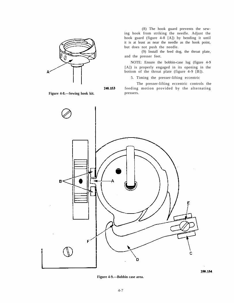
Figure 4-8.—Sewing hook kit.
(8) The hook guard prevents the sew-ing hook from striking the needle. Adjust thehook guard (figure 4-8 [A]) by bending it untilit is at least as near the needle as the hook point,but does not push the needle.
(9) Install the feed dog, the throat plate,and the presser feet.
NOTE: Ensure the bobbin-case lug (figure 4-9[A]) is properly engaged in its opening in thebottom of the throat plate (figure 4-9 [B]).
5. Timing the presser-lifting eccentric
The presser-lifting eccentric controls thefeeding motion provided by the al ternat ingpressers.
Figure 4-9.—Bobbin case area.
4-7
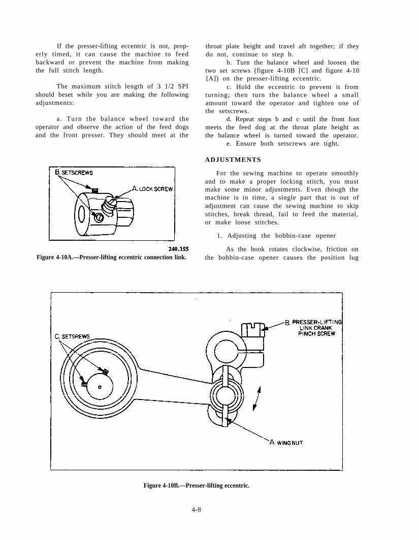
If the presser-lifting eccentric is not, prop- throat plate height and travel aft together; if theyerly timed, it can cause the machine to feed do not, continue to step b.backward or prevent the machine from making b. Turn the balance wheel and loosen thethe full stitch length. two set screws (figure 4-10B [C] and figure 4-10
[A]) on the presser-lifting eccentric.The maximum stitch length of 3 1/2 SPI c. Hold the eccentric to prevent it from
should beset while you are making the following turning; then turn the balance wheel a smalladjustments: amount toward the operator and tighten one of
the setscrews.a . Turn the balance wheel toward the d. Repeat steps b and c until the front foot
operator and observe the action of the feed dogs meets the feed dog at the throat plate height asand the front presser. They should meet at the the balance wheel is turned toward the operator.
e. Ensure both setscrews are tight.
ADJUSTMENTS
For the sewing machine to operate smoothlyand to make a proper locking stitch, you mustmake some minor adjustments. Even though themachine is in time, a single part that is out ofadjustment can cause the sewing machine to skipstitches, break thread, fail to feed the material,or make loose stitches.
1. Adjusting the bobbin-case opener
As the hook rotates clockwise, friction onFigure 4-10A.—Presser-lifting eccentric connection link. the bobbin-case opener causes the position lug
Figure 4-10B.—Presser-lifting eccentric.
4-8
(figure 4-9 [A]) to press against the back of itsopening. The bobbin-case opener moves thebobbin case counterclockwise to allow the threadto pass around the bobbin-case-opener lug. If theopener is adjusted too tight, damage to manyparts may occur; and if the opener is not set tightenough, extreme upper thread tension may benecessary to lock the stitch properly. Adjustingthe bobbin-case opener is accomplished asfollows:
a . Turn the balance wheel toward theoperator until the bobbin-case-opener lever (figure4-9 [C]) moves as far to the right as possible.
b. If the bobbin-case opener (figure 4-9[D]) has been removed, reinstall it at this time.Do not tighten the adjusting screw (figure 4-9 [E])at this time.
c. Place two thicknesses of paper, as agauge, between the tip of the bobbin-case openerand its projection on the bobbin case.
d. Move the bobbin-case opener right orleft as necessary to cause the bobbin case to moveas far to the right as possible without binding.
e . Tighten the bobbin-case-opener ad-justing screw.
f . Turn the balance wheel toward theo p e r a t o r a n d o b s e r v e t h e o p e r a t i o n o f t h ebobbin case and its opener. Ensure no binds arepresent and that the bobbin case is pul ledcounterclockwise as far as possible with eachrotation of the hook.
2. Adjusting the total relative lift of thealternating pressers
The total relative lift of the alternatingpressers referred to here is that the feet liftone-half inch at total lift. Maximum lift of thealternating pressers is set to sew on heavier goods.There are two types of adjustments, and eithertype may be found on a given machine. The firsttype of alternating presser (figure 4-10A) is usuallyfound on earlier sewing machines, while thesecond type of alternating presser (figure 4-10B)seems to be in current manufacture.
a. Adjusting the first type of alternatingpresser is accomplished as follows:
(1) Turn the balance wheel toward theoperator until the presser-lifting eccentric lockscrew (figure 4-10A [A]) is visible inside theopening at the back of the arm of the machine.(See figure 4-11 [A], table 4-3, foldout at end ofthis chapter.)
NOTE: Figure 4-10A shows two setscrews(B). They are used to hold the presser-liftingeccentric in place on the feed-driving rockshaft.The adjusting screw is not visible in this figure.
(2) Loosen the lock screw and turn thebalance wheel until the adjusting screw is visiblein the opening in the back of the arm. (See figure4-11 [A].)
(3) Turn the adjusting screw counter-clockwise to obtain maximum total lift of thepressers.
(4) Turn the balance wheel toward theoperator until the lock screw is visible in theopening in the back of the arm and retighten thelock screw.
b. Adjusting the second type of alternatingpresser is accomplished as follows:
(1) Loosen the presser-lifting eccentricadjusting wing nut (figure 4-10B [A]).
(2) Move the assembly up to decreasethe lift or down to increase the total lift of thealternating pressers.
(3) Tighten the wing nut.
3. Adjusting the relative lift of the alternatingpressers
The alternating presser feet should each liftt o app rox ima te ly t he s ame he igh t . Do no tconfuse relative lift with total lift. Here we areadjusting the presser feet to lift to approximatelythe same height. Adjusting the relative lift of thealternating pressers is accomplished as follows:
a . Turn the balance wheel toward theoperator and observe the action of the alternatingpressers. If they do not lift equally, proceed tostep b.
b. Turn the balance wheel until the footthat lifts too high is just above the throat plate.
c. Loosen the presser-lifting link crankpinch screw (figure 4-11 [B]). The foot shouldsnap down; if it does not, push it down.
d. Tighten the presser-lifting link crankpinch screw.
e. Repeat step a. If necessary repeat stepsb through d until the feet lift to the same height.
4. Adjusting the lifting linkage of the alter-nating pressers
To set the lifting linkage, you must loosenthe lifting crank pinch screw (figure 4-11 [B]) and
4-9
the presser bar lifting bracket pinch screw (figure4-11 [C]). Turn the balance wheel toward theoperator until the feed dogs rise to meet theforward presser foot at the top of the throat plate.Press the presser bar lifting bracket down to thehand lifting lever (figure 4-11 [D]). Tighten the----presser bar lifting bracket pinch screw (figure 4-11[C]) and the lifting crank pinch screw (figure 4-11—[B]).
5 . A d j u s t i n g t h e u p p e r t h r e a d - t e n s i o n -releasing lever
The upper thread-tension release allows thegoods to be removed without the needle threadbreaking.
a. Lift the presser-lifting lever and observethe thread tension disc. It should separate torelease the thread. If not, proceed as follows:
b. Remove the thread controller assemblyfrom the machine as follows:
(1) Remove the thread controller as-sembly retaining screw (figure 4-6 [1]).
(2) Loosen the thread controller studsetscrew (figure 4-6 [J]).
(3) Pull the thread controller assemblyaway from the machine.
c. Bend the thread releasing lever (figure4-12 [B]) away from the thread control lerassembly to increase the amount of the release andtoward the plate to decrease the tension as needed.
d. Reattach the assembly to the machineand observe the operation. Repeat steps a throughd if necessary.
6. Setting the feed indicator disc
Loosen the setscrew in the feed indicatordisc (figure 4-1 [E]) so that it spins on the armshaft. Depress the feed indicator plunger and turnthe balance wheel toward you until it drops; keepturning the balance wheel toward you until itstops. The feed-driving eccentric is now set at3 1/2 SPI.
NOTE: With the plunger engaged, turning thebalance wheel toward you decreases the SPI, andt u r n i n g t h e b a l a n c e w h e e l a w a y f r o m y o uincreases the SPI.
The ideal setting for the indicator disc onthe sewing machine is 8 SPI. You accomplish thissetting by engaging the plunger and turning the
balance wheel approximately one-fourth of a turnaway from you. Release the plunger, make severalinches of stitches on a piece of paper, and countthe total number of stitches per inch. If you aresewing 8 I, depress the plunger and slow/y turnthe balance wheel toward the operator until theplunger drops.
l S t o p .
. Release the plunger and the balancewheel.
. Now turn the feed indicator disc (figure4-1 [E]) on the arm shaft until 8 shows in thewindow on the uprise of your machine.
. T igh ten the s e t s c r ew in t he f eedindicator disc.
7. Setting the thread controller spring
The thread controller spring prevents theneedle from piercing the thread. It takes the slackout of the needle thread until the point of theneedle enters the material.
To properly set the tension on the threadcontroller spring, you must first loosen the threadcontroller stud setscrew on the tension stud (figure4-6 [J]). Turn the tension stud counterclockwisefor more tension or clockwise for less tension.
A properly adjusted controller spring restson the thread controller spring stop as the pointof the needle enters the material. This actionreleases all tension on the needle thread.
8. Setting the controller spring stop
You may have to make an adjustment tothe controller spring stop to allow the threadcontroller spring to operate properly. This is avery simple adjustment. By loosening the tensionstud screw, shown in figure 4-6 (I), you raise thestop for less action or lower it for more action.
9. Adjusting the thread tension
The thread tension will be the last adjust-ment required. In most cases, you can make anyadjustment required by turning the thumb nut(figure 4-12 [A]) on the needle thread tensiondisc.
I f the s t i tch is locking on top of thematerial , turn the nut counterclockwise. This
4-10
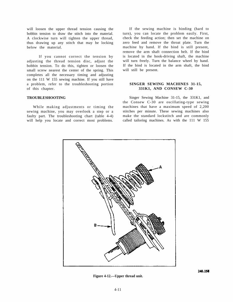
will loosen the upper thread tension causing thebobbin tension to draw the stitch into the material.A clockwise turn will tighten the upper thread,thus drawing up any stitch that may be lockingbelow the material.
I f you cannot correct the tension byadjusting the thread tension disc, adjust thebobbin tension. To do this, tighten or loosen thesmall screw nearest the center of the spring. Thiscompletes all the necessary timing and adjustingon the 111 W 155 sewing machine. If you still havea problem, refer to the troubleshooting portionof this chapter.
TROUBLESHOOTING
While making adjustments or t iming thesewing machine, you may overlook a step or afaulty part. The troubleshooting chart (table 4-4)will help you locate and correct most problems.
If the sewing machine is binding (hard toturn), you can locate the problem easily. First,check the feeding action; then set the machine onzero feed and remove the throat plate. Turn themachine by hand. If the bind is still present,remove the arm shaft connection belt. If the bindis located in the hook-driving shaft, the machinewill turn freely. Turn the balance wheel by hand.If the bind is located in the arm shaft, the bindwill still be present.
SINGER SEWING MACHINES 31-15,331K1, AND CONSEW C-30
Singer Sewing Machine 31-15, the 331K1, andthe Consew C-30 are oscillating-type sewingmachines that have a maximum speed of 2,200stitches per minute. These sewing machines alsomake the standard lockstitch and are commonlycalled tailoring machines. As with the 111 W 155
Figure 4-12.—Upper thread unit.
4-11
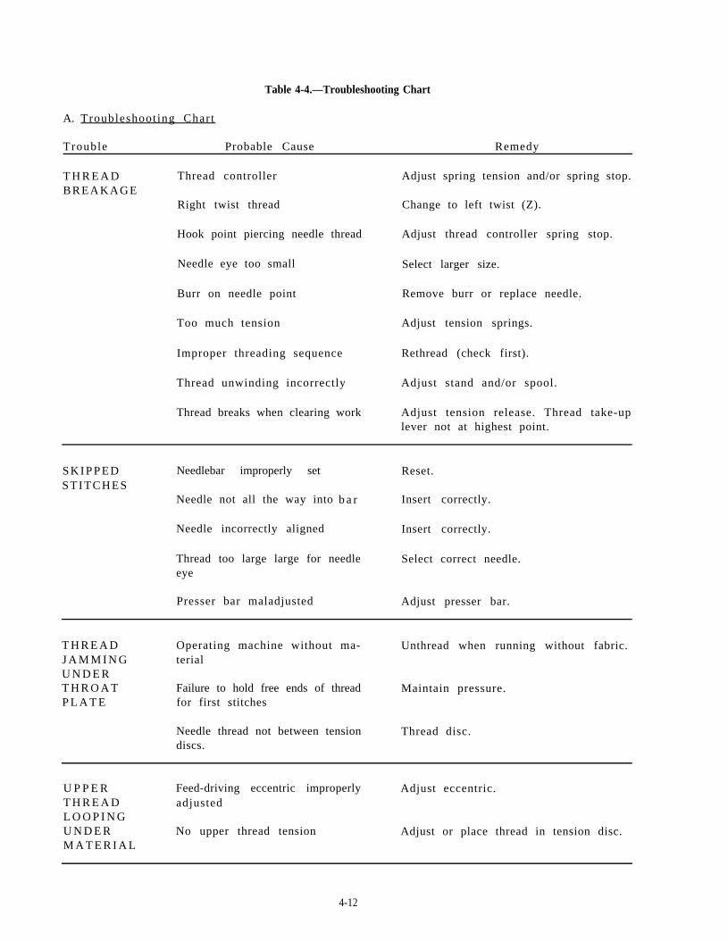
Table 4-4.—Troubleshooting Chart
A. Troubleshoot ing Chart
Trouble Probable Cause Remedy
T H R E A D Thread controller Adjust spring tension and/or spring stop.BREAKAGE
Right twist thread Change to left twist (Z).
Hook point piercing needle thread Adjust thread controller spring stop.
Needle eye too small Select larger size.
Burr on needle point Remove burr or replace needle..
Too much tension Adjust tension springs.
Improper threading sequence Rethread (check first).
Thread unwinding incorrectly Adjust stand and/or spool.
Thread breaks when clearing work Adjust tension release. Thread take-uplever not at highest point.
S K I P P E D Needlebar improperly setSTITCHES
Needle not all the way into
Needle incorrectly aligned
Reset.
b a r Insert correctly.
Insert correctly.
Thread too large large for needle Select correct needle.eye
Presser bar maladjusted Adjust presser bar.
T H R E A D Operating machine without ma- Unthread when running without fabric.J A M M I N G terialU N D E RT H R O A T Failure to hold free ends of thread Maintain pressure.P L A T E for first stitches
Needle thread not between tension Thread disc.discs.
U P P E R Feed-driving eccentric improperly Adjust eccentric.T H R E A D adjustedL O O P I N GU N D E R No upper thread tension Adjust or place thread in tension disc.M A T E R I A L
4-12
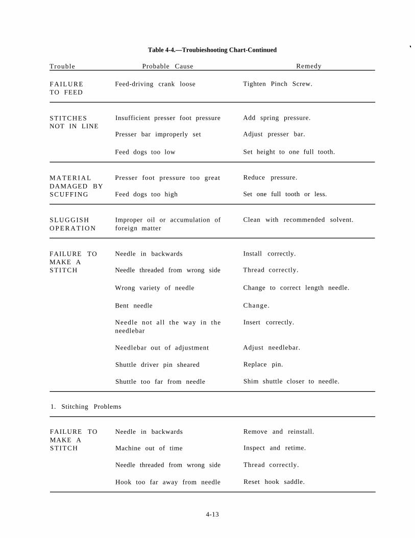
Table 4-4.—Troubieshooting Chart-Continued
Trouble Probable Cause Remedy
F A I L U R E Feed-driving crank loose Tighten Pinch Screw.TO FEED
STITCHES Insufficient presser foot pressure Add spring pressure.NOT IN LINE
Presser bar improperly set Adjust presser bar.
Feed dogs too low Set height to one full tooth.
M A T E R I A L Presser foot pressure too great Reduce pressure.DAMAGED BYS C U F F I N G Feed dogs too high Set one full tooth or less.
S L U G G I S H Improper oil or accumulation of Clean with recommended solvent.O P E R A T I O N foreign matter
FAILURE TO Needle in backwardsMAKE ASTITCH Needle threaded from wrong side
Wrong variety of needle
Bent needle
Needle not al l the way in theneedlebar
Needlebar out of adjustment
Shuttle driver pin sheared
Shuttle too far from needle
Install correctly.
Thread correctly.
Change to correct length needle.
Change.
Insert correctly.
Adjust needlebar.
Replace pin.
Shim shuttle closer to needle.
1. Stitching Problems
FAILURE TO Needle in backwards Remove and reinstall.MAKE ASTITCH Machine out of time Inspect and retime.
Needle threaded from wrong side Thread correctly.
Hook too far away from needle Reset hook saddle.
4-13
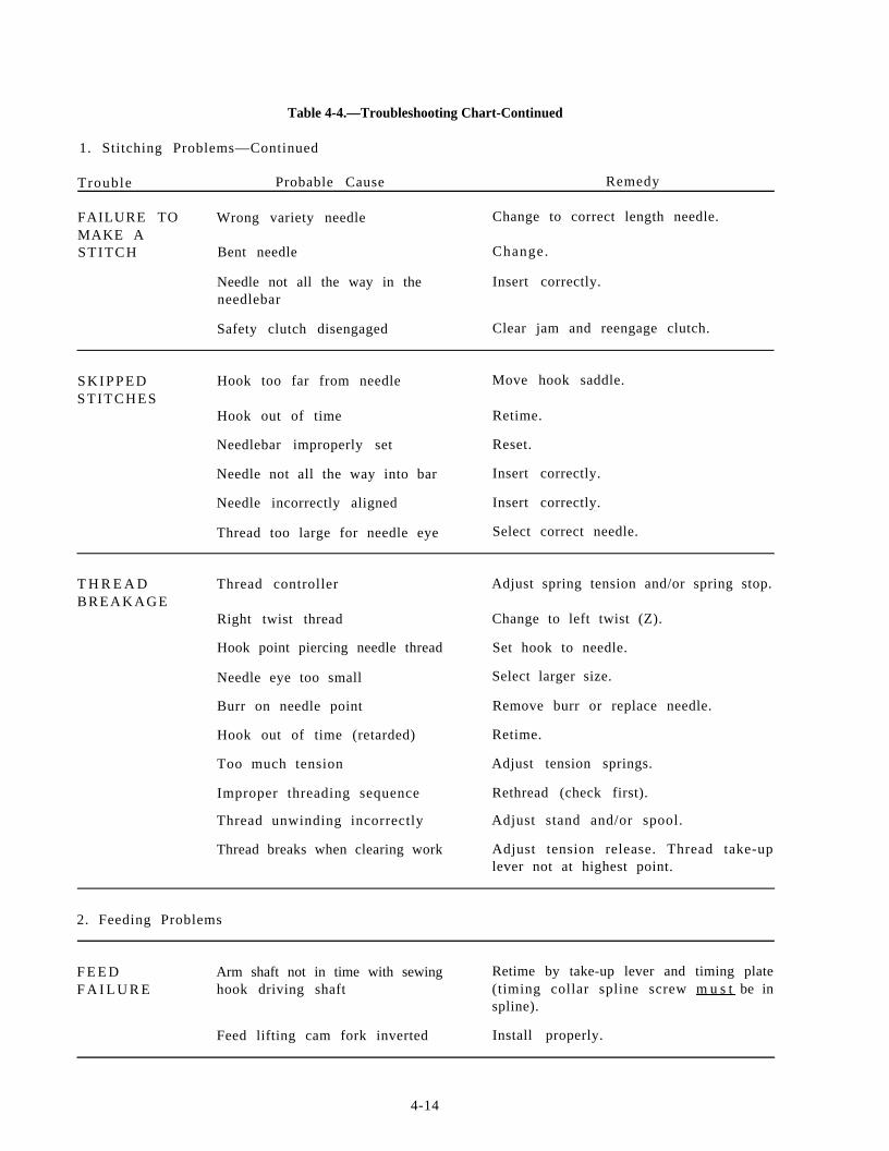
Table 4-4.—Troubleshooting Chart-Continued
1. Stitching Problems—Continued
Trouble Probable Cause Remedy
FAILURE TO Wrong variety needle Change to correct length needle.MAKE ASTITCH Bent needle Change.
Needle not all the way in the Insert correctly.needlebar
Safety clutch disengaged Clear jam and reengage clutch.
S K I P P E D Hook too far from needle Move hook saddle.STITCHES
Hook out of time Retime.
Needlebar improperly set Reset.
Needle not all the way into bar Insert correctly.
Needle incorrectly aligned Insert correctly.. .
Thread too large for needle eye Select correct needle.
T H R E A D Thread controller Adjust spring tension and/or spring stop.BREAKAGE
Right twist thread Change to left twist (Z).
Hook point piercing needle thread
Needle eye too small
Burr on needle point
Hook out of time (retarded)
Too much tension
Improper threading sequence
Thread unwinding incorrectly
Thread breaks when clearing work
Set hook to needle.
Select larger size.
Remove burr or replace needle.
Retime.
Adjust tension springs.
Rethread (check first).
Adjust stand and/or spool.
Adjust tension release. Thread take-uplever not at highest point.
2. Feeding Problems
F E E D Arm shaft not in time with sewing Retime by take-up lever and timing plateF A I L U R E hook driving shaft (timing collar spline screw m u s t be in
spline).
Feed lifting cam fork inverted Install properly.
4-14
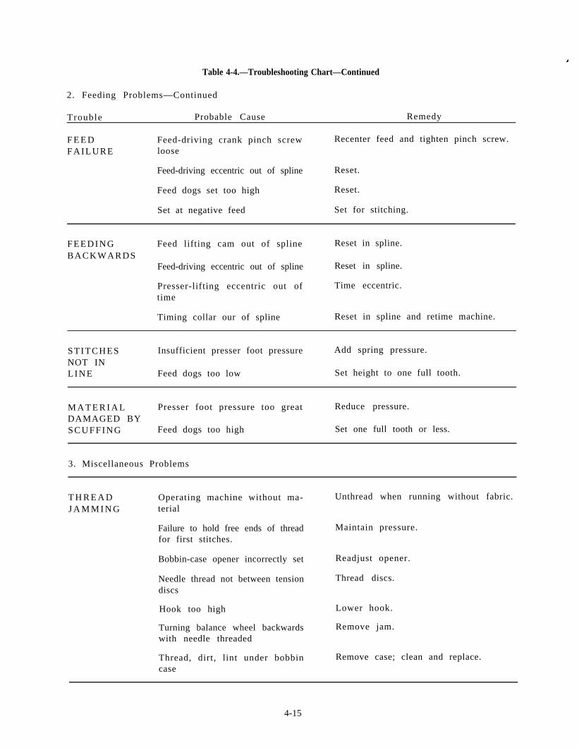
Table 4-4.—Troubleshooting Chart—Continued
2. Feeding Problems—Continued
Trouble Probable Cause Remedy
F E E D Feed-driving crank pinch screw Recenter feed and tighten pinch screw.F A I L U R E loose
Feed-driving eccentric out of spline Reset.
Feed dogs set too high Reset.
Set at negative feed Set for stitching.
F E E D I N G Feed lifting cam out of spline Reset in spline.BACKWARDS
Feed-driving eccentric out of spline Reset in spline.
Presser-lifting eccentric out of Time eccentric.time
Timing collar our of spline Reset in spline and retime machine.
STITCHES Insufficient presser foot pressure Add spring pressure.NOT INL I N E Feed dogs too low Set height to one full tooth.
M A T E R I A L Presser foot pressure too great Reduce pressure.DAMAGED BYS C U F F I N G Feed dogs too high Set one full tooth or less.
3. Miscellaneous Problems
T H R E A D Operating machine without ma- Unthread when running without fabric.J A M M I N G terial
Failure to hold free ends of thread Maintain pressure.for first stitches.
Bobbin-case opener incorrectly set Readjust opener.
Needle thread not between tension Thread discs.discs
Hook too high Lower hook.
Turning balance wheel backwards Remove jam.with needle threaded
Thread, dirt, lint under bobbin Remove case; clean and replace.case
4-15
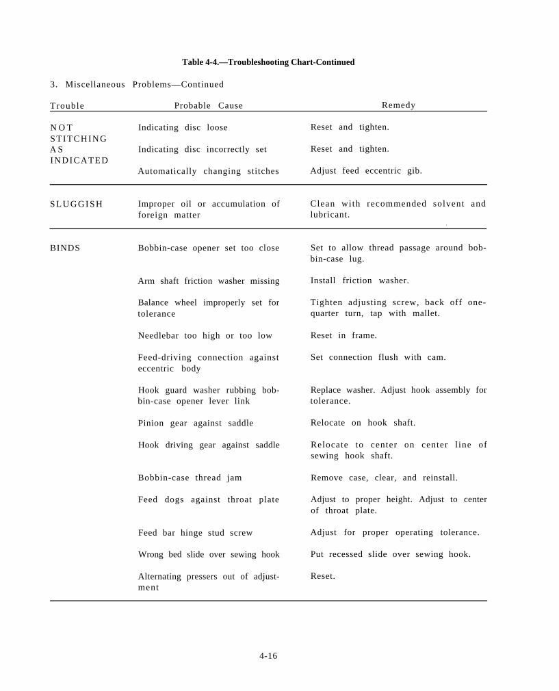
Table 4-4.—Troubleshooting Chart-Continued
3. Miscellaneous Problems—Continued
Trouble Probable Cause Remedy
N O T Indicating disc loose Reset and tighten.S T I T C H I N GA S Indicating disc incorrectly set Reset and tighten.I N D I C A T E D
Automatically changing stitches Adjust feed eccentric gib.
S L U G G I S H Improper oil or accumulation of Clean with recommended solvent andforeign matter lubricant.
.
BINDS Bobbin-case opener set too close
Arm shaft friction washer missing
Balance wheel improperly set fortolerance
Needlebar too high or too low
Feed-driving connection againsteccentric body
Hook guard washer rubbing bob-bin-case opener lever link
Pinion gear against saddle
Hook driving gear against saddle
Bobbin-case thread jam
Feed dogs against throat plate
Feed bar hinge stud screw
Wrong bed slide over sewing hook
Alternating pressers out of adjust-ment
Set to allow thread passage around bob-bin-case lug.
Install friction washer.
Tighten adjusting screw, back off one-quarter turn, tap with mallet.
Reset in frame.
Set connection flush with cam.
Replace washer. Adjust hook assembly fortolerance.
Relocate on hook shaft.
Relocate to center on center l ine ofsewing hook shaft.
Remove case, clear, and reinstall.
Adjust to proper height. Adjust to centerof throat plate.
Adjust for proper operating tolerance.
Put recessed slide over sewing hook.
Reset.
4-16
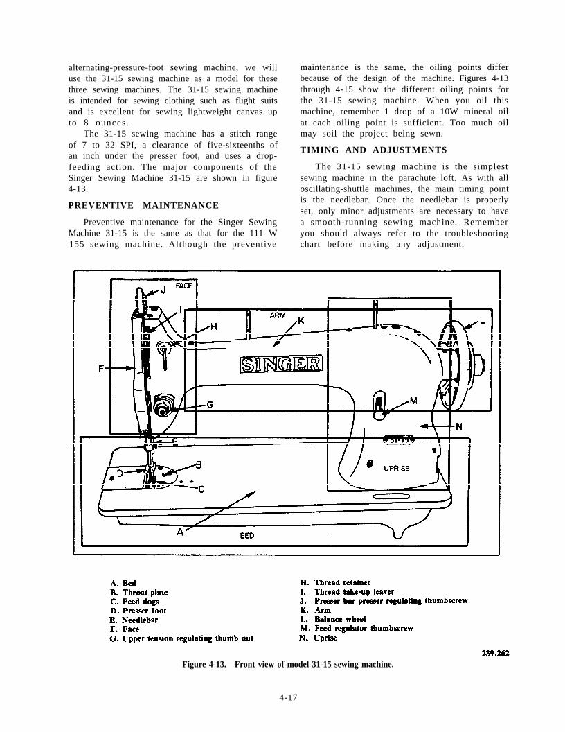
alternating-pressure-foot sewing machine, we willuse the 31-15 sewing machine as a model for thesethree sewing machines. The 31-15 sewing machineis intended for sewing clothing such as flight suitsand is excellent for sewing lightweight canvas upto 8 ounces .
The 31-15 sewing machine has a stitch rangeof 7 to 32 SPI, a clearance of five-sixteenths ofan inch under the presser foot, and uses a drop-feeding action. The major components of theSinger Sewing Machine 31-15 are shown in figure4-13.
PREVENTIVE MAINTENANCE
Preventive maintenance for the Singer SewingMachine 31-15 is the same as that for the 111 W
maintenance is the same, the oiling points differbecause of the design of the machine. Figures 4-13through 4-15 show the different oiling points forthe 31-15 sewing machine. When you oil thismachine, remember 1 drop of a 10W mineral oilat each oiling point is sufficient. Too much oilmay soil the project being sewn.
TIMING AND ADJUSTMENTS
The 31-15 sewing machine is the simplestsewing machine in the parachute loft. As with alloscillating-shuttle machines, the main timing pointis the needlebar. Once the needlebar is properlyset, only minor adjustments are necessary to havea smooth-running sewing machine. Rememberyou should always refer to the troubleshooting
155 sewing machine. Although the preventive chart before making any adjustment.
Figure 4-13.—Front view of model 31-15 sewing machine.
4-17
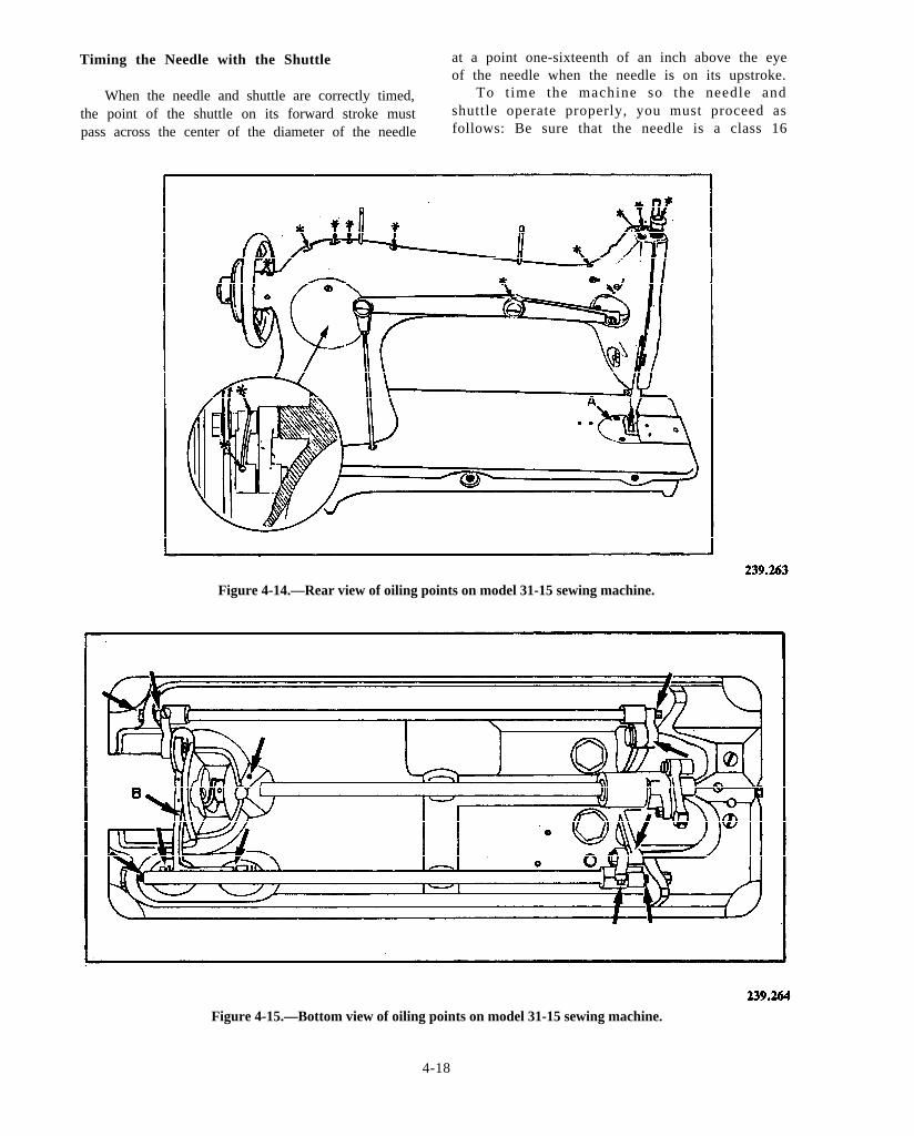
Timing the Needle with the Shuttle at a point one-sixteenth of an inch above the eyeof the needle when the needle is on its upstroke.
When the needle and shuttle are correctly timed, To t ime the machine so the needle and
the point of the shuttle on its forward stroke must shuttle operate properly, you must proceed as
pass across the center of the diameter of the needle follows: Be sure that the needle is a class 16
Figure 4-14.—Rear view of oiling points on model 31-15 sewing machine.
Figure 4-15.—Bottom view of oiling points on model 31-15 sewing machine.
4-18
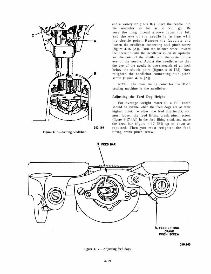
Figure 4-16.—Setting needlebar.
and a variety 87 (16 x 87). Place the needle intothe needlebar as far as it will go. Besure the long thread groove faces the lef tand the eye o f t he need le i s i n l i ne w i ththe shutt le point . Remove the faceplate andloosen the needlebar connecting stud pinch screw(figure 4-16 [A]). Turn the balance wheel towardthe operator until the needlebar is on its upstrokeand the point of the shuttle is in the center of theeye of the needle. Adjust the needlebar so thatthe eye of the needle is one-sixteenth of an inchbelow the shuttle point (figure 4-16 [B]). Nowretighten the needlebar connecting stud pinchscrew (figure 4-16 [A]).
NOTE: The main timing point for the 31-15sewing machine is the needlebar.
Adjusting the Feed Dog Height
For average weight material, a full toothshould be visible when the feed dogs are at theirhighest point. To adjust the feed dog height, youmust loosen the feed lifting crank pinch screw(figure 4-17 [A]) in the feed lifting crank and movethe feed bar (figure 4-17 [B]) up or down asrequired. Then you must ret ighten the feedlifting crank pinch screw.
Figure 4-17.—Adjusting feed dogs.
4-19
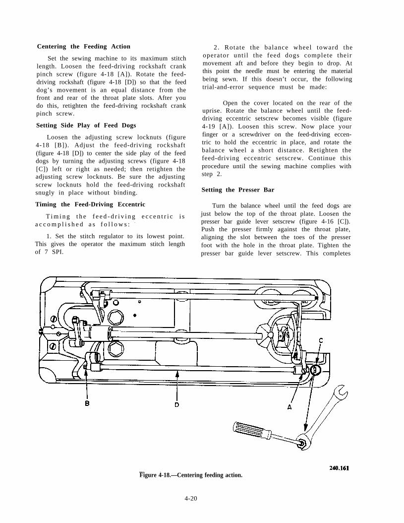
Centering the Feeding Action
Set the sewing machine to its maximum stitchlength. Loosen the feed-driving rockshaft crankpinch screw (figure 4-18 [A]). Rotate the feed-driving rockshaft (figure 4-18 [D]) so that the feeddog’s movement is an equal distance from thefront and rear of the throat plate slots. After youdo this, retighten the feed-driving rockshaft crankpinch screw.
Setting Side Play of Feed Dogs
Loosen the adjusting screw locknuts (figure4-18 [B]). Adjust the feed-driving rockshaft(figure 4-18 [D]) to center the side play of the feeddogs by turning the adjusting screws (figure 4-18[C]) left or right as needed; then retighten theadjusting screw locknuts. Be sure the adjustingscrew locknuts hold the feed-driving rockshaftsnugly in place without binding.
Timing the Feed-Driving Eccentric
T i m i n g t h e f e e d - d r i v i n g e c c e n t r i c i sa c c o m p l i s h e d a s f o l l o w s : -
1. Set the stitch regulator to its lowest point.This gives the operator the maximum stitch lengthof 7 SPI.
2. Rotate the balance wheel toward theoperator unt i l the feed dogs complete theirmovement aft and before they begin to drop. Atthis point the needle must be entering the materialbeing sewn. If this doesn’t occur, the followingtrial-and-error sequence must be made:
Open the cover located on the rear of theuprise. Rotate the balance wheel until the feed-driving eccentric setscrew becomes visible (figure4-19 [A]). Loosen this screw. Now place yourfinger or a screwdriver on the feed-driving eccen-tric to hold the eccentric in place, and rotate thebalance wheel a short distance. Retighten thefeed-driving eccentric setscrew. Continue thisprocedure until the sewing machine complies withstep 2.
Setting the Presser Bar
Turn the balance wheel until the feed dogs arejust below the top of the throat plate. Loosen thepresser bar guide lever setscrew (figure 4-16 [C]).Push the presser firmly against the throat plate,aligning the slot between the toes of the presserfoot with the hole in the throat plate. Tighten thepresser bar guide lever setscrew. This completes
Figure 4-18.—Centering feeding action.
4-20
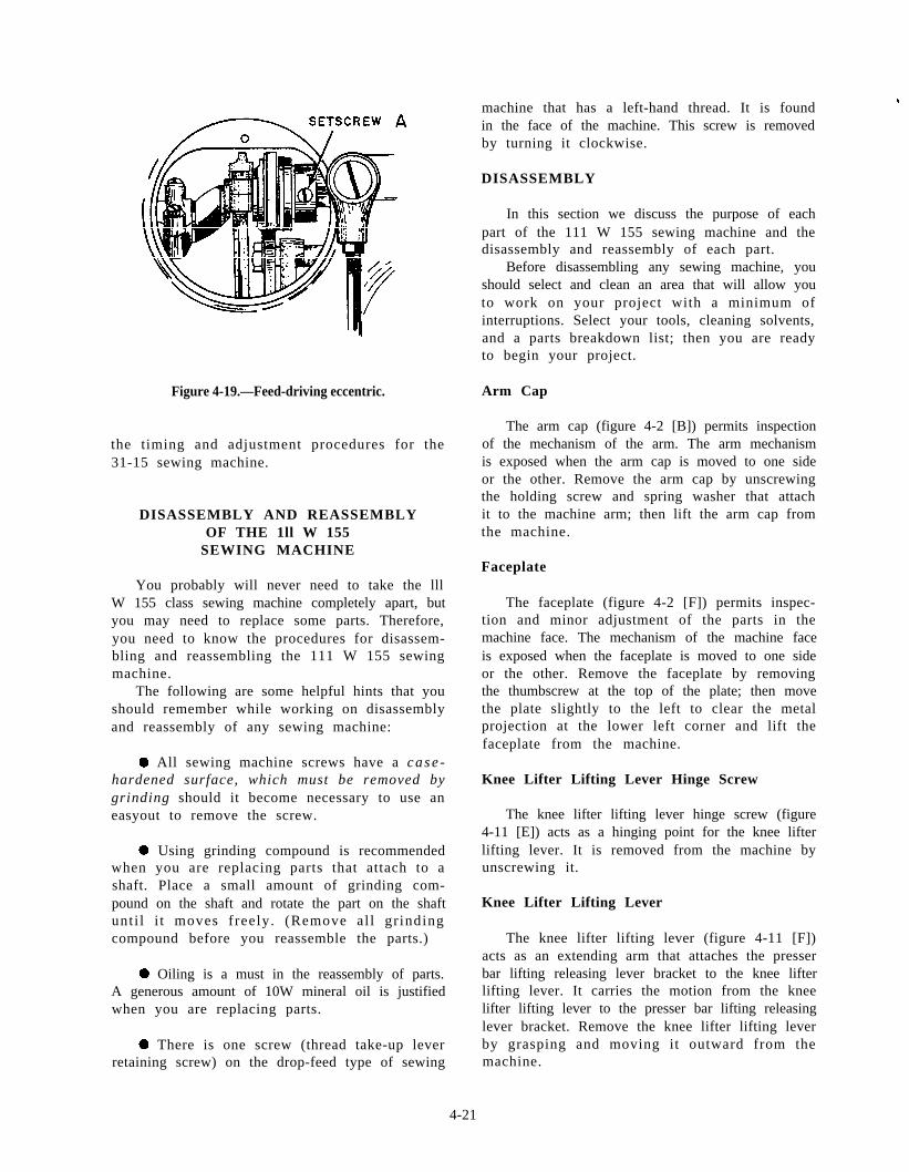
Figure 4-19.—Feed-driving eccentric.
the timing and adjustment procedures for the31-15 sewing machine.
DISASSEMBLY AND REASSEMBLYOF THE 1ll W 155
SEWING MACHINE
You probably will never need to take the lllW 155 class sewing machine completely apart, butyou may need to replace some parts. Therefore,you need to know the procedures for disassem-bling and reassembling the 111 W 155 sewingmachine.
The following are some helpful hints that youshould remember while working on disassemblyand reassembly of any sewing machine:
. All sewing machine screws have a case -hardened surface, which must be removed bygrinding should it become necessary to use aneasyout to remove the screw.
. Using grinding compound is recommendedwhen you are replacing parts that attach to ashaft. Place a small amount of grinding com-pound on the shaft and rotate the part on the shaftunti l i t moves freely. (Remove al l gr indingcompound before you reassemble the parts.)
l Oiling is a must in the reassembly of parts.A generous amount of 10W mineral oil is justifiedwhen you are replacing parts.
. There is one screw (thread take-up leverretaining screw) on the drop-feed type of sewing
machine that has a left-hand thread. It is found#
in the face of the machine. This screw is removedby turning it clockwise.
DISASSEMBLY
In this section we discuss the purpose of eachpart of the 111 W 155 sewing machine and thedisassembly and reassembly of each part.
Before disassembling any sewing machine, youshould select and clean an area that will allow youto work on your project with a minimum ofinterruptions. Select your tools, cleaning solvents,and a parts breakdown list; then you are readyto begin your project.
Arm Cap
The arm cap (figure 4-2 [B]) permits inspectionof the mechanism of the arm. The arm mechanismis exposed when the arm cap is moved to one sideor the other. Remove the arm cap by unscrewingthe holding screw and spring washer that attachit to the machine arm; then lift the arm cap fromthe machine.
Faceplate
The faceplate (figure 4-2 [F]) permits inspec-tion and minor adjustment of the parts in themachine face. The mechanism of the machine faceis exposed when the faceplate is moved to one sideor the other. Remove the faceplate by removingthe thumbscrew at the top of the plate; then movethe plate slightly to the left to clear the metalprojection at the lower left corner and lift thefaceplate from the machine.
Knee Lifter Lifting Lever Hinge Screw
The knee lifter lifting lever hinge screw (figure4-11 [E]) acts as a hinging point for the knee lifterlifting lever. It is removed from the machine byunscrewing it.
Knee Lifter Lifting Lever
The knee lifter lifting lever (figure 4-11 [F])acts as an extending arm that attaches the presserbar lifting releasing lever bracket to the knee lifterlifting lever. It carries the motion from the kneelifter lifting lever to the presser bar lifting releasinglever bracket. Remove the knee lifter lifting leverby grasping and moving it outward from themachine.
4-21
Presser Bar Spring Support Screw
The presser bar spring-support screw (figure4-11 [G]) acts as a suspension point for the presserbar spring. The screw is loosened approximatelyone-fourth of - an inch to allow for the removalof the presser bar spring. Do not remove thep r e s s e r b a r s p r i n g - s u p p o r t s c r e w f r o m t h emachine.
Presser Bar Spring
The presser bar spring (figure 4-11 [H])applies a constant pressure to the presser bar. Toremove the presser bar spring from the machine,l ower t he p r e s se r f e e t and t hen g r a sp t heunderside of the spring as near the support screwas possible with two fingers of one hand over twofingers of the other hand. Now slide the springoutward to the head of the support screw,rolling the spring up and out of the machine.
Presser Bar Lifting ReleasingLever Bracket Guide Screw
The presser bar lifting releasing lever bracketguide screw, (figure 4-11 [1]) acts as a track andguide for the presser bar lifting releasing leverbracket. Remove the presser bar lifting releasinglever bracket guide screw by unscrewing it fromthe machine.
Presser Bar Position Guide
The presser bar position guide (figure 4-7 [D])acts as a track to control the presser bar positionguide lever. To remove the presser bar positionguide, you should loosen (six turns) the splinescrew on the rear side nearest the face of themachine and push the guide through the recessat the top of the machine head.
Presser Bar Position Guide Lever
The presser bar position guide lever is used toalign the presser foot, and it operates in the slotof the presser bar guide.
NOTE: The presser bar position guide doesnot screw out. Loosen the pinch screw on thepresser bar position guide lever (figure 4-11 [K])by inserting the screwdriver into the opening onthe rear s ide of the machine head. This isnecessary to allow movement of the presser barfor the removal of attached parts.
Alternating Presser Foot
The alternating presser foot is the rear presserfoot and holds the material in place while theneedle and front presser foot move forwardmaking another bight. To remove the rear presserfoot, you unscrew the presser foot position screwon the left side of the presser bar. Raise the presserbar to its highest position and remove the footfrom the rear.
Presser Bar Spring Bracket
The presser bar spring bracket (figure 4-7 [E])transfers the tension from the presser bar springto the presser bar. To loosen the presser bar springb r a c k e t f r o m t h e p r e s s e r b a r , i n s e r t t h escrewdriver through the lower opening providedin the back of the face of the machine. Loosenthe presser bar lifting bracket pinch screw (figure4-11 [C]). Remove the presser bar lifting bell crankretaining screw and lifting bell crank (figure 4-7[F] and [G]). Now remove the presser bar (figure4-7 [M]) in a slow upward motion.
Presser-Lifting Bell Crank
The presser- l i f t ing bel l crank al ternatelyapplies l i f t to the presser feet . Remove thepresser-lifting bell crank retaining screw (figure4-7 [F]) and then extract the bell crank (figure 4-7[G]) from the machine.
Presser Bar Lifting Bracket
The presser bar lifting bracket is alternatelya hinge point and lifting point for the two presserbars. It is also the controlling part for the presserfeet while work is being inserted and removed,and it gives support to the thread tension releaseslide.
CAUTION
If binding should occur while you arer e m o v i n g t h e p r e s s e r b a r , i n s e r t ascrewdriver into the lower slot of thepresser bar and rotate it while applyingupward motion on the presser bar.
When you remove the presser bar, thefollowing parts will fall off: the presser barspring bracket (figure 4-7 [E]), the releasingbracket, the releasing bracket spring, thelifting bracket, and the guide lever.
4-22
l Now remove the vibrating presser barconnecting link (figure 4-7 [N]) from the face ofthe machine.
. Loosen the presser-lifting link crank pinchscrew (figure 4-11 [B]). Rotate the presser-liftingrockshaf t ( f igure 4-11 [M]) away from themachine about 90 degrees. Remove the presser-lifting bell crank connection from its stud. Nowremove the presser-lifting rockshaft; then removethe presser-lifting link crank (figure 4-11 [P]) fromits connection link.
Needlebar Rock Frame Position Bracket
The needlebar rock frame position bracket(figure 4-7 [H]) holds the needlebar rock framein position and prevents any side-to-side play.To remove the needlebar rock frame positionbracket , you remove the holding screw andwithdraw the bracket from the machine.
Tension Release Rod
The tension release lever rod releases thetension on the thread. This allows the thread tobe pulled freely when you remove material fromthe machine. When the presser bar is lifted, theshoulder on the arm of the presser bar liftingreleasing slide bracket presses the tension releaserod, thereby releasing the tension on the thread.You remove the tension release rod by tilting themachine backward and allowing the rod to slidefrom its recess. Unscrew and remove the vibratingpresser foot tension spring adjustment thumb-screw (figure 4-11 [Q]). At this point, you canremove the vibrating presser foot (figure 4-11[R]).
Vibrating Presser Foot
The vibrating presser foot is the foremost foot.It moves fore and aft as well as up and down, andcombines its actions with that of the needle andthe feed dogs.
Needlebar Rock Frame Hinge Stud
The needlebar rock frame hinge stud (figure4-7 [I]) acts as a hinging point for the needlebarrock frame. To remove the needlebar rock framehinge stud, you loosen the setscrew on the top ofthe machine head; then you press the hinge studout through the face of the machine.
Needlebar Rock Frame Assembly
The needlebar rock frame assembly (figure 4-7[O]) consists of seven major parts: the needlebarconnecting stud, the needlebar, the needlebar rockframe, the needlebar rock frame slide block, thevibrating presser bar, the vibrating presser barspring, and the presser bar spring guide rod. Toremove the needlebar rock frame assembly, yougrasp it and withdraw it from the face of themachine.
Needlebar Connecting Link Oil Guard
The needlebar connecting link oil guard (figure4-11 [J]) prevents oil from being thrown throughthe thread take-up lever groove. To remove theneedlebar connecting link oil guard, you insert thescrewdriver in the opening in the rear of themachine face, remove the holding screw and thenremove the oil guard.
Take-up Lever Hinge Stud
The take-up lever hinge stud acts as a hingingpoint for the thread take-up lever. To remove thetake-up lever hinge stud, first you loosen thesetscrew located three-fourths of an inch to theright of the thread take-up lever; then you insertthe screwdriver in the oil hole and push the take-up lever hinge stud out through the face of themachine.
Thread Take-up Lever
The thread take-up lever pulls the slack outof the needle thread to lock the stitch in the goodsbeing sewn. To remove the thread take-up lever,you turn the balance wheel until the needlebarconnecting link is at its lowest position; thenwithdraw the thread take-up lever through theface of the machine.
Thread Take-up Lever Driving Stud
The thread take-up lever driving stud transferspower and motion from the needlebar connectinglink to the thread take-up lever. The threadtake-up lever driving stud is attached to the threadtake-up lever; they are removed from the machineat the same time.
Needlebar Connecting Link
The needlebar connecting link (figure 4-7 [J])changes the rotary motion of the needlebar crank
4-23
to the vertical motion of the needlebar. Removethe needlebar connecting link by grasping it andthen withdrawing it from the face of the machine.
Balance Wheel Adjusting Screw
The balance- wheel adjusting screw (figure 4-11[L]) eliminates end play in the balance wheel andarm shaft. Remove the balance wheel adjustmentscrew.
Balance Wheel
The balance wheel (figures 4-6 [R] and 4-11[N]) transfers the motion and power from the one-third-horsepower electric motor to the arm shaft.To remove the balance wheel, you must firstloosen the two setscrews attaching it to the armshaft; then you withdraw it from the machine.
NOTE: The balance wheel is very fragile. Donot hit it with a hammer to remove it.
Arm Shaft Connection Belt
The arm shaft connection belt (figure 4-4 [A])transfers the power and motion from the armshaft connection belt pulley to the safety clutchpulley. To remove the arm shaft connection belt,you insert a small screwdriver along the left edgeand slide the belt from the safety clutch pulley.
Arm Shaft Connection BeltPulley Position Screw
The arm shaft connection belt pulley positionscrew holds the pulley in a freed position. The armshaft connection belt pulley position screw is thelarger of the two screws on the pulley. The smallerscrew is a setscrew. It must be loosened but notremoved from the pulley. Remove the arm shaftconnection belt pulley position screw by unscrew-ing it.
NOTE: For machines with ball bearings, thearm shaft arm bushing setscrews are located justto the right of the connection belt pulley. Theysecure the arm shaft bushing to the arm shaft.These screws are not removed from the bushing;however, they must be loosened for the arm shaftto be removed.
The Presser-Lifting Eccentric
The presser- l i f t ing eccentr ic supplies thelift for the alternating presser feet. Free the
presser-lifting eccentric by loosening the twopresser-lifting eccentric setscrews located throughthe opening in the rear of the arm (figure 4-11[A]). You must rotate the balance wheel to loosenthe second screw. Be sure the eccentric rotatesfreely on the shaft.
Feed Indicator Disc
The feed indicator disc shows the operator thenumber of s t i tches per inch the machine issewing. It also allows the operator to set themachine to sew a desired number of stitches perinch. Loosen the feed indicator disc setscrew andensure the disc will rotate freely on the shaft.
Needlebar Crank
The needlebar crank transfers the motion andpower from the arm shaft to the needlebar by theneedlebar dr iving s tud. Do not remove theneedlebar crank from the arm shaft.
Needlebar Connecting Link Stud
The needlebar connecting link stud transfersthe motion and power from the needlebar crankto the needlebar connecting link. Do not removethe needlebar connecting link stud from the armshaft.
Needlebar Crank Friction Washer
The needlebar crank friction washer acts asa bearing surface between the needlebar crank andthe front arm shaft bushing. In some cases theneedlebar crank friction washer remains with themachine upon removal of the arm shaft bushing.If this occurs, insert the index finger in the armshaft recess and remove the washer.
NOTE: The operator must be especial lycareful when assembling the machine to becertain the needlebar crank friction washer isr e tu rned t o t he a rm sha f t . Absence o f t heneedlebar crank friction washer will cause themachine to bind.
Arm Shaft
The arm shaft (figure 4-11 [0]) acts as acarrier for, and transfers the power and motionto, the arm shaft connection belt pulley, the feedindicator disc, the needlebar crank fr ict ionwasher, and the needlebar crank. To remove
4 - 2 4
the arm shaft, grasp it with the left hand andwithdraw it from the face of the machine.
Right- and Left-Hand Bed Slide Plates
The bed slide plates allow for inspection andmaintenance of the bobbin assembly. The right-hand bed slide has a cutout on the bottom side.This cutout allows the needle thread to pass overthe bobbin case without jamming.
Throat Plate
The throat plate acts as a guide for the feeddog and provides a firm foundation over whichthe material may flow while the stitch is beingmade. The throat plate does not need to beremoved from the machine.
Needlebar Rock Frame Rockshaft
The needlebar rock frame rockshaft carries thefeeding motion and power from the feedingmechanism in the bed of the machine to theneedlebar rock frame. To remove the needlebarrock frame rockshaft, you insert the screwdriverin the opening in the rear of the uprise and loosenthe needlebar rock frame rockshaft crank pinchscrew. Remove t he need l eba r r ock f r amerockshaft from the face of the machine.
Needlebar Rock FrameRockshaft Crank and Connection
The needlebar rock frame rockshaft crank andconnection transfers the feeding motion andpower from the feed-driving rockshaft crank tothe needlebar rock frame rockshaft. To removethe needlebar rock frame rockshaft crank andconnection, you loosen the pinch screw at thefeed-driving rockshaft crank (figure 4-6 [G]).Then you grasp the feed-driving rockshaft crank(figure 4-6 [H]), slide it to the right to remove itfrom the feed-driving rockshaft, and withdraw itfrom the machine. In so doing, the needlebar rockframe rockshaft crank and connection parts arealso removed. The parts removed remain as anassembly.
Feed-Driving Rockshaft Crank
The feed-driving rockshaft crank transfers thefeeding motion of the feed-driving rockshaft tothe needlebar rock frame rockshaft crank andconnection. The feed-driving rockshaft crank is
removed simultaneously with the needlebar rockframe rockshaft crank and connection.
Feed-Lifting Cam Fork
The feed-lifting cam fork gives the feed dogi ts up and down motion during the feedingoperation. To remove the feed-lifting cam fork,you unscrew the feed-lifting cam fork screw(figure 4-6 [E]), tilt the fork toward the operator,and withdraw it.
Feed-Driving Rockshaft
The feed-driving rockshaft (figure 4-6 [L])coordinates the feeding motion of the feed dogand the feeding of the needle. To remove the feed-driving rockshaft , proceed in the fol lowingmanner (refer to figure 4-6):
. Loosen the hook saddle adjusting screw(figure 4-6 [B]).
. Loosen the hook saddle pinch screw (figure4-6 [A]).
. Slide the hook saddle to the right as faras possible.
. Loosen the feed-driving rockshaft crankpinch screw (figure 4-6 [G]).
. Loosen the setscrews on each of the feed-driving rockshaft stop collars (figure 4-6 [M]).
l Lif t the feed bar toward the operatoruntil it reaches a stop position. Move the bar tothe left until it strikes the bed of the machine. Liftthe bar upward to clear the bed of the machineand continue moving it to the left until the rightend of the shaft reaches the feed-driving crank;this action forces the right feed-driving rockshaftstop collar from the rockshaft. Continue movingthe rockshaft to the lef t unt i l i t c lears theleft stop collar. Withdraw the rockshaft from themachine.
Feed-Driving Rockshaft Stop Collars
The feed-driving rockshaft stop collars andsetscrews (figure 4-6 [M]) act as retainers on eachend of the feed-driving rockshaft to prevent anyside-to-side play. The feed-driving rockshaft stopcollars are removed in conjunction with thefeed-driving rockshaft.
4-25
Feed Bar
The feed bar (figure 4-6 [F]) transfers thepower and motion from the feed-driving rockshaftto the feed dog.
Feed Dog
The feed dog aids the needle in feeding thematerial to the machine. It is attached to the feedb a r l
Hook-Driving Shaft and Attached Parts
The removal of the hook-driving shaft (figure4-6 [N]) begins with the loosening of the attachedparts, starting from the right and working to theleft .
. Loosen the setscrew and the spline screwin the hook-driving shaft bearing collar. (Seefigure 4-6 [O].)
. Loosen the two setscrews in the hook-driving shaft lock ratchet. (See figure 4-6 [P].)
NOTE: Mach ines f i t t ed wi th ca s t i ronbushings instead of ball bearings will have onlyone spline screw.
. Loosen the spline screw and the setscrewsin the feed-driving eccentric. (See figure 4-6([Q].)
l Loosen the hook saddle pinch screw (figure4-6 [A]).
l Loosen the two setscrews in the hook-driving gear.
. Loosen the spline screw in the feed-liftingeccentric (figure 4-6 [T]).
NOTE: After you loosen the spline screw andthe setscrews, each part must rotate freely on theshaft .
Safety Clutch Pulley
The purpose of the safety clutch pulley (figure4-4 [D]) is twofold. First, it is used to transfer thepower and motion from the arm shaft connectionbelt to the hook-driving shaft; second, it protectsthe hook from being damaged by disengagingwhen the hook is jammed. To remove the safety
4-26
clutch pulley, you loosen the two setscrews (figure4-6 [S]) that attach the safety clutch pulley to thehook-driving shaft and withdraw the pulley.
Feed-Lifting Eccentric
The feed-lifting eccentric (figure 4-6 [T])supplies a l i f t ing motion to the feed-l if t ingeccentric fork. Remove the feed-lifting eccentricby moving the hook-driving shaft to the right untilit clears the feed-lifting eccentric, thus allowingthe eccentric to drop from the shaft.
Hook-Driving Gear
T h e h o o k - d r i v i n g g e a r c o n v e r t s t h elongitudinal motion in the hook-driving shaft tothe hor izontal motion on the sewing hook.Remove the hook-driving gear by moving thehook-driving shaft to the right until it clears thehook-driving gear, thus allowing the hook-drivinggear to drop from the shaft.
Feed-Driving Eccentric
The feed-driving eccentric sets up the motionand controls the feeding mechanism of the sewingmachine. Remove the feed-driving eccentric bymoving the hook-driving shaft to the right untilit clears the feed-driving eccentric, thus allowingit to drop from the shaft.
Feed-Driving Connection
The feed-driving connection carries the feedingmotion to the feed-driving crank. Remove thefeed-driving connection simultaneously with thefeed-driving eccentric. Remove the connectionfrom the eccentric by withdrawing it from theeccentric.
Feed-Driving Crank
The feed-driving crank transfers the feedingmotion from the feed-driving connection to thefeed-driving rockshaft. The feed-driving crank isattached to the feed-driving connection and isremoved from the sewing machine when youremove the feed-driving connection.
Hook-Driving Shaft Lock Ratchet
The hook-driving shaft lock ratchet locks thehook-driving shaft in position while you set thesafety clutch. Remove the hook-driving shaft
lock ratchet by moving the hook-driving shaft tothe right until it clears the hook-driving shaft lockratchet, thus allowing it to drop from the shaft.
Arm Shaft Connection Belt TimingCollar and Hook-Driving ShaftBall-Bearing Collar
The arm shaft connection belt timing collarand the hook-driving shaft ball-bearing collar arethe initial timing points on the machine. Do notremove these parts from the machine. In machinesfitted with cast iron bushings, the timing collarwill fall off as the shaft is withdrawn.
Hook-Driving Shaft
The hook-dr iving shaf t ( f igure 4-6 [N])transfers power and motion to the units attachedto it. To remove the hook-driving shaft, you graspit and withdraw it to the right.
Bobbin-Case Opener
The bobbin-case opener (figure 4-9 [D]) actsas a lever to pull the bobbin case back from thethroat plate. It allows the needle thread to passbetween the bobbin case and the throat plate. Toremove the bobbin-case opener, you unscrew theadjusting screw (figure 4-9 [E]) and lift it fromthe hook saddle assembly.
Hook Saddle Screw
The hook saddle screw (figure 4-6 [B]) holdsthe hook saddle assembly in place. Unscrew thehook saddle screw to remove it.
Hook Saddle Assembly
The hook saddle assembly (figure 4-6 [U])forms the lower half of the stitch. To remove thehook saddle assembly, unscrew the hook saddlescrew and loosen the hook saddle pinch screw(figure 4-6 [A]). Draw the hook saddle assemblyslightly toward the operator, slide it to the leftunt i l i t c lears the center hook-driving shaftbushing, and withdraw it from the machine. Thiscompletes the disassembly of the sewing machine.
REASSEMBLY
Before reassembling the sewing machine, youwill need some grinding compound to smoothparts that may have surface rust or small burrs.
A small amount of grinding compound on thesurface is sufficient. Rotate the two parts untilthey move freely. You will also need some 10Wmineral oil to lubricate all moving parts. Afteryou accomplish these tasks, proceed as followsto reassemble the sewing machine.
Hook Saddle Assembly
To replace the hook saddle assembly, hold itin an upright position with the saddle clampfacing the bed of the machine; then place thesaddle clamp on the edge of the center hook-driving shaft bushing. Swing the hook saddleassembly toward the bed of the machine and slideit to the right and into place in the opening in thecasting.
Hook Saddle Screw
With the hook saddle assembly as far to theright as it will go, replace the hook saddle screwand tighten it.
Bobbin-Case Opener
Lift the machine to the upright position.Replace the bobbin-case opener so that the curvedend points toward the bobbin case. Replace thebobbin-case opener adjusting screw and tighten it.
Hook-Driving Shaft
Tilt the machine forward. In replacing thehook-driving shaft, you should note that it hasfive splined grooves. One of the splined groovesis located at one end of the shaft. Insert the endwithout a splined groove into the right hook-driving shaft bearing.
Hook-Driving Shaft Lock Ratchet
As the hook-driving shaft is pushed towardthe left, or face, of the machine, replace the hook-driving shaft lock ratchet so that the flange withthe setscrews faces the left of the machine.
Feed-Driving Connectionand Feed-Driving Crank
Hold the feed-driving eccentric with the flangeand spring to the right; then place the feed-drivingconnection, with the feed-driving crank attached,over the cam on the feed-driving eccentric. Be surethe oiling felt faces upward and the crank istoward the operator.
4-27
Feed-Driving Eccentric
Holding the feed-driving eccentric in the samemanner as stated above, you replace it on thehook-driving shaft.
Hook-Driving Gear
Push the hook-driving shaft through the centerhook-driving shaft bushing. Replace the hook-driving gear so that the flange with the setscrewsis facing toward the left.
Feed-Lifting Eccentric
Place the feed-lifting eccentric on the hook-driving shaft and slide the hook-driving shaftinto the front hook-driving shaft bushing, leavingapproximately 2 inches of the hook-driving shaftextended to the right of the rear hook-drivingshaft bushing.
Safety Clutch Pulley
Replace the safety clutch pulley so that thesafety clutch hook-driving shaft stop collar, withthe screws in it, is flush with the right end of thehook-driving shaft. Turn the safety clutch pulleyuntil the spline screw marked with the letter S i spositioned over the spline in the hook-drivingshaft. Tighten the spline screw and the setscrew.
Feed-Driving Rockshaft
The cylinder end of the feed-driving rockshaftis placed from the left into the feed-drivingrockshaft bushing. The flat side of the feed-driving rockshaft stop collar is placed flush withthe bushing, and the rockshaft is moved forwardto enter the stop collar. The feed-driving crankis placed next to the stop collar, and the rockshafti s m o v e d f o r w a r d t o e n t e r t h e c r a n k . T h eremaining stop collar is placed on the rockshaftwith the flat side to the right. The rockshaft (withthe base of the feed bar toward the operator) ismoved through and 1 inch past the right bushing.Holding the base of the feed bar toward you,rotate the rockshaft downward toward the bed ofthe machine and fit the feed dog into the throatplate.
Place the feed-lifting eccentric fork over thefeed-lifting eccentric and fit the base of the feedbar into the slot at the top of the feed-liftingeccentric fork. When the feed-lifting eccentricfork is in position, the rounded end of the fork
4-28
will be facing you. To secure the feed-liftingeccentric fork to the feed dog, you must place thefeed eccentric fork screw into the space providedand tighten it.
The feed-driving rockshaft crank is attachedto the needlebar rock frame rockshaft crank andconnection. To replace it, insert the needlebarrock frame rockshaft crank and connection withthe curved portion upward and the crank hangingdown into the arm through the opening in the bedof the machine. Slide the feed-driving rockshaftcrank over the feed-driving rockshaft. Do nottighten the crank. Ensure all other screws aretight.
This completes the assembly of the parts inthe bed of the machine. Now we will assemble theparts located in the arm of the machine.
Needlebar Rock Frame Rockshaft
(At this point, the machine is placed in anupright position.) Place the needlebar rock framerockshaft in the lower bushing in the face of themachine. Push it through until the end of the shaftis flush with the bushing in the arm of themachine. This may be viewed through the openingin t he t op o f t he mach ine a rm. P l ace t hescrewdriver through the opening in the right sideof the machine arm and engage the needlebar rockframe rockshaft crank. Lift the crank with thescrewdriver so that it is on line with the needlebarrock frame rockshaft. With the left hand, pushthe rockshaft through the crank. Do not tightenthe crank.
Arm Shaft
In replacing the arm shaft, be certain that theneedlebar crank friction washer is on the shaft.Insert the arm shaft in the top bushing in the faceof the machine; then push it through until it canbe seen through the opening located on the rearof the machine arm.
Presser-Lifting EccentricConnection Link
Insert the larger end of the presser-liftingeccentric connection link (figure 4-10A) with theoil holes facing up. Slowly push the arm shaftthrough the arm of the machine until you can seethe arm shaft at the opening on the top of themachine nearest the balance wheel.
Presser-Lifting Eccentric
Place the presser-lifting eccentric (figure4-10B) onto the arm shaft with the small endtoward the face of the machine. At this time, slidethe presser-lifting eccentric toward the face untilit goes inside the connecting link.
Feed Indicator Disc
The feed indicator disc is placed on the armshaft, through the opening in the top of themachine arm, so that the numbers on the disc maybe read right side up. Push the arm shaft throughthe disc about 1 inch.
Arm Shaft Pulley and ArmShaft Connection Belt
The arm shaft connection belt acts as a slingfor the arm shaft pulley. Use the belt and lowerthe pulley through the opening in the top of themachine arm. Now turn the belt, while aligningthe pulley with the arm shaft, and insert the shaftthrough the pulley. Be sure you push the shaftthrough as far as it will go.
Arm Shaft ConnectionBelt Pulley Position Screw
To replace the arm shaft connection beltpulley position screw, you hold the arm shaft inposition with the left hand and move the arm shaftpulley to the left. Turn the arm shaft until the holeis facing up. Now turn the pulley until the holefor the position screw is facing up. Move thepulley to the right, aligning the two holes, andinsert the position screw. Tighten the remainingsetscrew in the pulley.
Balance Wheel
Before you replace the balance wheel, turn thearm shaft until the groove in the shaft is facingupward. Place the balance wheel on the arm shaft.Now turn the wheel toward the operator until thesecond screw is directly in line with the groove.Tighten the screw in place. Tighten the remain-ing setscrew.
Balance Wheel Adjusting Screw
Place the balance wheel adjusting screw in theend of the arm shaft and tighten it. Loosen it one-quarter turn and strike it with a sharp blow
using a rawhide mallet. See that the balance wheelturns freely and that there is no play. If thebalance wheel does not turn, or if it turns andthere is side-to-side play, repeat the procedure.
CAUTION
This balance wheel is made of cast ironor aluminum and will break if you hit itdirectly with the mallet.
If the screw can be removed by using yourthumb and forefinger, it will be necessary tospread the end of the screw. To do this, removethe screw and spread the end of i t wi th ascrewdriver. Replace the screw and run it downuntil it touches the balance wheel. It should thenbe tightened snugly when you try to remove it withyour fingers.
Alternating Presser Driving Rockshaft
Slide the rockshaft into the rear of the machinethrough the two bushings. Attach the presser-lifting link crank to the link projecting from thearm. Continue sliding the rockshaft through thecrank. Set the machine on its balance wheel end.Install the bell crank link on the rockshaft stud(oil holes up). Install the oil guard into the faceat this time.
Needlebar Connecting Link
Turn the balance wheel until the needlebarconnecting link stud is at its lowest position. Graspthe needlebar connecting link so that the doublecylinders are up. Place the larger of the twocylinders over the needlebar connecting link stud,and ensure that the flush end of the cylinders arefacing outward.
Take-up Lever Driving Stud
Place the cylinder of the take-up leverdriving stud over the piston of the take-up lever.
Take-up Lever
Grasp the take-up lever with the piston of thetake-up lever driving stud and the cylinder of thetake-up lever facing the face of the machine. Fitthe lever into the slot designed for its operation;at the same time insert the take-up lever drivingstud into the remaining cylinder of the needlebarconnecting link.
4-29
Thread Take-up Lever Hinge Stud
Align the cylinder of the thread take-up leverwith the recess for the hinge stud. Before youinsert the hinge stud, turn the hinge stud and notethe flat machined surface running the length ofthe stud. Replace the stud with the machinedsurface up. Install the setscrew.
Needlebar Rock Frame Assembly
Hold the needlebar rock frame in the left handwith the rounded end up and the straight sidefacing left. Insert the slide block in the spaceprovided with the oil hole facing up.
Before you insert the needlebar rock frameassembly, turn the balance wheel unt i l theneedlebar connecting link is at its lowest position.Insert the assembly into the face of the machineso that the connecting stud enters the connectingl ink and the s l ide block is placed over theprojection on the needlebar rock frame rockshaft.At the same time, the vibrating presser barspringguide rod with the spr ing at tached must bepositioned into the hole at the top of the face.Hold the assembly in position.
While you are holding the assembly in position,insert the hinge stud so that the flat surface is up.Install and tighten the setscrew.
Install the needlebar rock frame. Positionbracket in position and tighten it in place.
Thread Tension Release Lever Rod
Insert the thread tension release lever rod inthe hole in the back of the machine head so thatthe rounded end is facing toward the operator.
Presser Bar
Inser t the presser bar through the upperbushing located in the top of the machine head,about 3 1/2 inches. Place the presser bar positionbar guide lever so that the pinch screw is to therear and the arm is to the left. At this time thelifting-and-releasing unit must be installed. Itconsists of a lifting bracket, a releasing bracket,and a spring that separates the two parts. Whileyou are holding the unit together, place it into theface so that the two long levers cover the releasingrod. Now twist the presser bar down through theunit. Before you lower the presser bar throughthe lower bushing, insert the presser bar springbracket with the slot up. Lower the presser barthrough the lower bushing. Turn it so that the
4-30
unthreaded end of the hole faces left. Insert thepresser foot in the slot. Replace the screw andtighten it.
Presser Bar Position Guide
Place the slot ted end of the presser barposition guide through the opening in the top ofthe machine head so that it fits over the arm ofthe presser bar position guide lever. When youcomplete this step, the top of the presser barposition guide will be flush with the top of themachine head. Tighten the spline screw in the rearof the head.
Presser Bar Spring
Tilt the machine down and place the longcurved end of the presser bar spring through theopening in the back of the machine head andinto the slot in the presser bar spring bracket.Place the small curved end over the presser barspring-support screw. Push it down and under thepresser spr ing-regulat ing screw. Tighten thepresser bar spring-support screw. Install the largeguide screw.
NOTE: Preadjust the spring bracket with thepresser foot firmly on the throat plate, and makesure the foot is straight. Raise the presser barspring bracket about one-eighth inch and tightenthe pinch screw.
. At this time, adjust the presser bar guidelever one-quarter inch up from the bottom of theguide as in figure 4-7 (K).
. Tighten the pinch screw (figure 4-11 [B]).
Front Presser Bar Connecting Link
Place the large end of the line on the frontpresser bar stud.
Bell Crank
The bell crank has three attachment points:(1) the bell crank connection link, (2) the liftinglever bell crank stud, and (3) the front presser barconnecting link stud. All three must be engagedat the same time. Install and tighten the retainingscrew.
Front Presser Foot and PresserPressure-Regulating Thumbscrew
Install the foot on the front presser foot andthe regulating screw on the top of the face.
Knee Lifter Lifting Lever
Replace the knee lifter lifting lever so that theslotted end fits over the projection on the kneelifter connection lever. The projection on thecurved end of the knee lifter lifting lever fits underthe presser bar releasing bracket.
Knee Lifter Lifting Lever Hinge Screw
Align the hole in the knee lifter lifting leverwith the corresponding hole in the machine
arm; then insert the hinge screw. Make certain thescrew, including the shoulder, is fully inserted.
Faceplate
Insert the thumbscrew and secure it.
Arm Cap
Replace the arm cap and the spring washer onthe machine arm and screw them in place.
This completes the reassembly of the 111 W155 sewing machine. It will be necessary to makea few minor adjustments or retime this machine.T iming and ad ju s tmen t a r e cove red a t t hebeginning of this chapter.
4-31

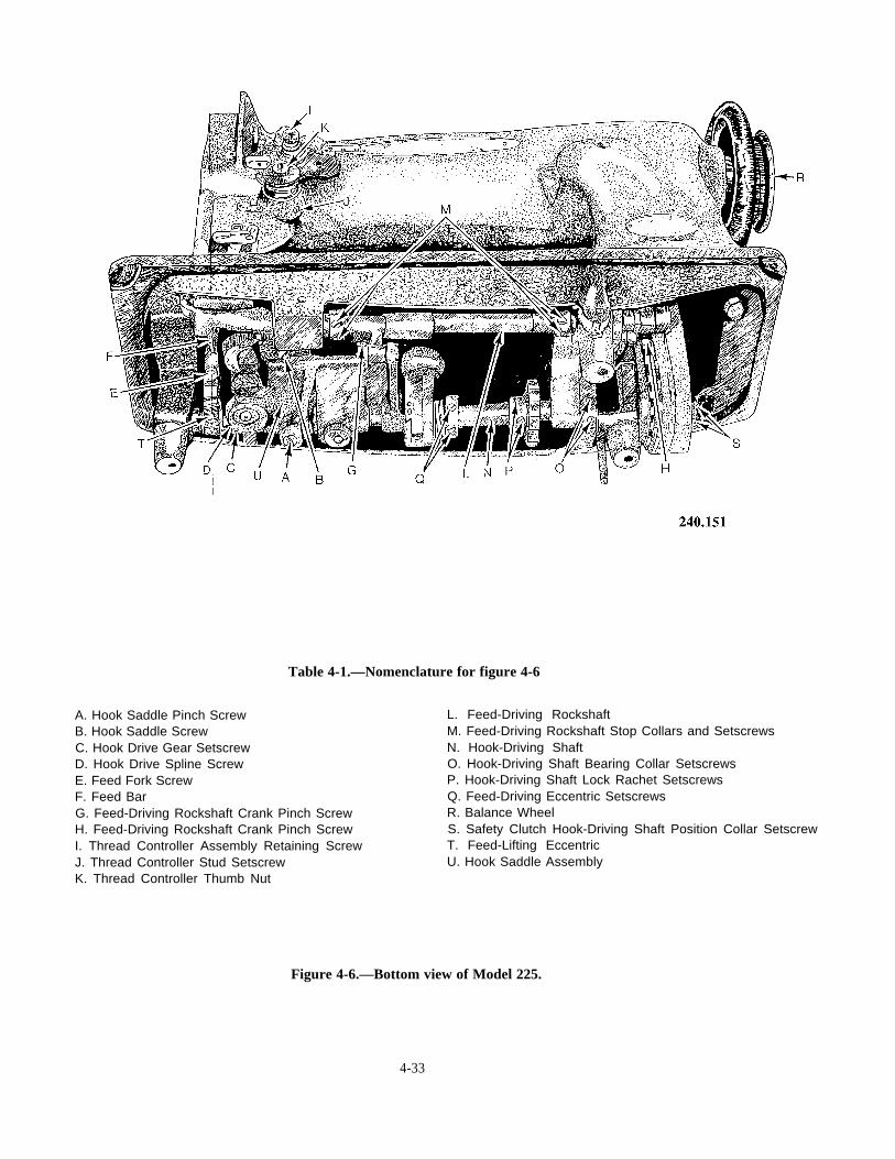
Table 4-1.—Nomenclature for figure 4-6
A. Hook Saddle Pinch ScrewB. Hook Saddle ScrewC. Hook Drive Gear SetscrewD. Hook Drive Spline ScrewE. Feed Fork ScrewF. Feed BarG. Feed-Driving Rockshaft Crank Pinch ScrewH. Feed-Driving Rockshaft Crank Pinch ScrewI. Thread Controller Assembly Retaining ScrewJ. Thread Controller Stud SetscrewK. Thread Controller Thumb Nut
L. Feed-Driving RockshaftM. Feed-Driving Rockshaft Stop Collars and SetscrewsN. Hook-Driving ShaftO. Hook-Driving Shaft Bearing Collar SetscrewsP. Hook-Driving Shaft Lock Rachet SetscrewsQ. Feed-Driving Eccentric SetscrewsR. Balance WheelS. Safety Clutch Hook-Driving Shaft Position Collar SetscrewT. Feed-Lifting EccentricU. Hook Saddle Assembly
Figure 4-6.—Bottom view of Model 225.
4-33

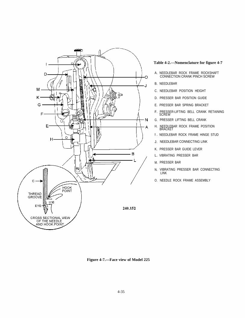
Table 4-2.—Nomenclature for figure 4-7
A.
B.
C.
D.
E.
F.
G.
H.
I .
J.
K.
L.
M.
N.
O.
NEEDLEBAR ROCK FRAME ROCKSHAFTCONNECTION CRANK PINCH SCREW
NEEDLEBAR
NEEDLEBAR POSITION HEIGHT
PRESSER BAR POSITION GUIDE
PRESSER BAR SPRING BRACKET
PRESSER-LIFTING BELL CRANK RETAININGSCREW
PRESSER LIFTING BELL CRANK
NEEDLEBAR ROCK FRAME POSITIONBRACKET
NEEDLEBAR ROCK FRAME HINGE STUD
NEEDLEBAR CONNECTING LINK
PRESSER BAR GUIDE LEVER
VIBRATING PRESSER BAR
PRESSER BAR
VIBRATING PRESSER BAR CONNECTINGLINK
NEEDLE ROCK FRAME ASSEMBLY
Figure 4-7.—Face view of Model 225
4-35

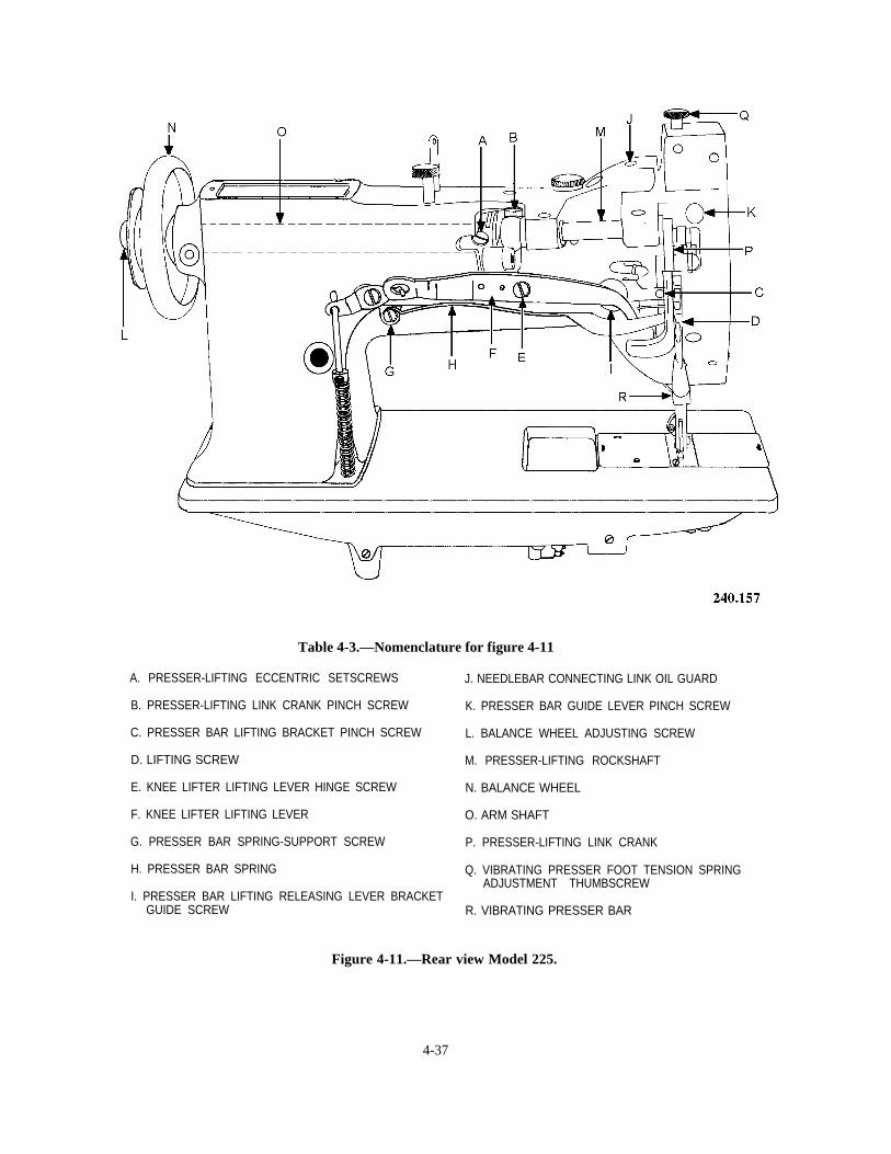
Table 4-3.—Nomenclature for figure 4-11
A. PRESSER-LIFTING ECCENTRIC SETSCREWS J. NEEDLEBAR CONNECTING LINK OIL GUARD
B. PRESSER-LIFTING LINK CRANK PINCH SCREW K. PRESSER BAR GUIDE LEVER PINCH SCREW
C. PRESSER BAR LIFTING BRACKET PINCH SCREW L. BALANCE WHEEL ADJUSTING SCREW
D. LIFTING SCREW M. PRESSER-LIFTING ROCKSHAFT
E. KNEE LIFTER LIFTING LEVER HINGE SCREW N. BALANCE WHEEL
F. KNEE LIFTER LIFTING LEVER O. ARM SHAFT
G. PRESSER BAR SPRING-SUPPORT SCREW P. PRESSER-LIFTING LINK CRANK
H. PRESSER BAR SPRING Q. VIBRATING PRESSER FOOT TENSION SPRINGADJUSTMENT THUMBSCREW
I. PRESSER BAR LIFTING RELEASING LEVER BRACKETGUIDE SCREW R. VIBRATING PRESSER BAR
Figure 4-11.—Rear view Model 225.
4-37

CHAPTER 5
AIRCREW SURVIVALEQUIPMENT TRAINING
During the Southeast Asian conflict, a prece-dent of immediate rescue was established. Theaverage period of individual, isolated survivalfor aircrew members that were rescued was 6hours. The average time in the southwest Pacificduring World War II was 48 hours in 85 percentof the cases reported. The marked reduction intimes can be attributed to a number of factors,including aircrew familiarity with equipment,efficiency of air rescue and/or recovery forces,more effective communications devices, rotary-wing rescue vehicles, and most significantly, theprevailing low-threat air environment. However,in a future major conflict, the United Statescannot expect to have the same air superiority thatit had in Southeast Asia.
The United States now anticipates a sophis-ticated high-threat air environment with a widespectrum of antiaircraft weapons. We can expectgreater combat losses with more downed aircraftand aircrew members. The fate of search andrescue (SAR) helicopters and their support aircraftis in doubt against an enemy equipped withmodern air defense weapons. Thus, U.S. militarypersonnel must be prepared both mentally andphysically for long-term solitude, as well as groupsurvival, with all of the problems involved, untilrescue can be effected.
The basic ski l ls for survival have neverchanged. The will to live and survive is still themost important single factor in bringing air-crewmen home alive.
Today’s survival equipment used by air-crewmen has been improved over the past 10 yearsto a point where, with a little common sense andproper instruction on its use, the aircrewman hasa better chance of survival than ever before.
Until now you have inspected, tested, andpacked survival items. Maybe on occasions youhave been required to give a lecture on the useof survival items. As a first class or chief pettyofficer, it is essential that you be familiar withsurvival equipment and ensure flight personnel aretrained in its use. The following manuals and
instructions will aid you in your research forinformation about the survival environment andequipment usage. NWP 19-1 is the Navy’s SARmanual. This manual describes all aspects ofsearch, rescue, and the equipment used in rescueoperations. The NAVAIR 00-80T-101, SurvivalTraining Manual, is a recently published manualwith which you may not be familiar. It describesthe use of survival equipment and rescue devicescarried by Navy aircrewmen and SAR vehicles.This includes electronic, pyrotechnic, and survivalequipment, as well as specialized SAR rescueequipment . The NATOPS General Flight andOperating Instructions, OPNAVINST 3710.7 ,provides general information about minimumrequirements for aircrew personnel protectionequipment and training.
SEA SURVIVAL
Most naval aircraft are equipped for androutinely fly over water; so chances are, a highpercentage of our survival situations will involvethe sea. All aircrewmen flying in naval aircrafthave received training in water survival, and mostare good swimmers. You will not be involved inteaching swimming. Your job is to instruct theaircrewman in the use of avai lable survivalequipment.
If you are to survive in the sea, you will haveto remain calm and use sound judgment; panicwill be your worst enemy. Mental preparation andpractice will allow you to use your fear construc-tively. You should mentally rehearse your actionsmany times so that when you are forced to act,it will be from conditioned reflex. By the time youreach the water, whether by parachute or crashlanding, you will know your situation and beginto apply established priorities. It is beyond thescope of this text to attempt to detail everysurvival scenario. However, you will improve yourchances to survive in the sea, despite the variablefactors such as environmental conditions, sea
5-1
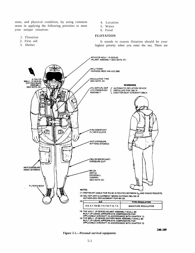
state, and physical condition, by using commonsense in applying the following priorities to meetyour unique situation:
1. Flotation2. First aid3. Shelter
4. Location5. Water6. Food
FLOTATION
It stands to reason flotation should be yourhighest priority when you enter the sea. There are
Figure 5-1.—Personal survival equipment.
5-2
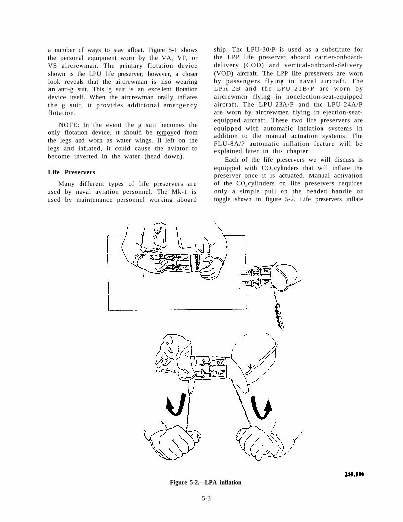
a number of ways to stay afloat. Figure 5-1 showsthe personal equipment worn by the VA, VF, orVS aircrewman. The primary flotation deviceshown is the LPU life preserver; however, a closerlook reveals that the aircrewman is also wearingan anti-g suit. This g suit is an excellent flotationdevice itself. When the aircrewman orally inflatesthe g sui t , i t provides addit ional emergencyflotation.
NOTE: In the event the g suit becomes theonly flotation device, it should be removed from—-- —the legs and worn as water wings. If left on thelegs and inflated, it could cause the aviator tobecome inverted in the water (head down).
Life Preservers
Many different types of life preservers areused by naval aviation personnel. The Mk-1 isused by maintenance personnel working aboard
ship. The LPU-30/P is used as a substitute forthe LPP life preserver aboard carrier-onboard-delivery (COD) and vertical-onboard-delivery(VOD) aircraft. The LPP life preservers are wornby passengers f lying in naval a i rcraf t . TheL P A - 2 B a n d t h e L P U - 2 1 B / P a r e w o r n b yaircrewmen flying in nonelection-seat-equippedaircraft. The LPU-23A/P and the LPU-24A/Pare worn by aircrewmen flying in ejection-seat-equipped aircraft. These two life preservers areequipped with automatic inflation systems inaddition to the manual actuation systems. TheFLU-8A/P automatic inflation feature will beexplained later in this chapter.
Each of the life preservers we will discuss isequipped with CO2 cylinders that will inflate thepreserver once it is actuated. Manual activationof the CO2 cylinders on life preservers requiresonly a simple pull on the beaded handle ortoggle shown in figure 5-2. Life preservers inflate
Figure 5-2.—LPA inflation.
5-3
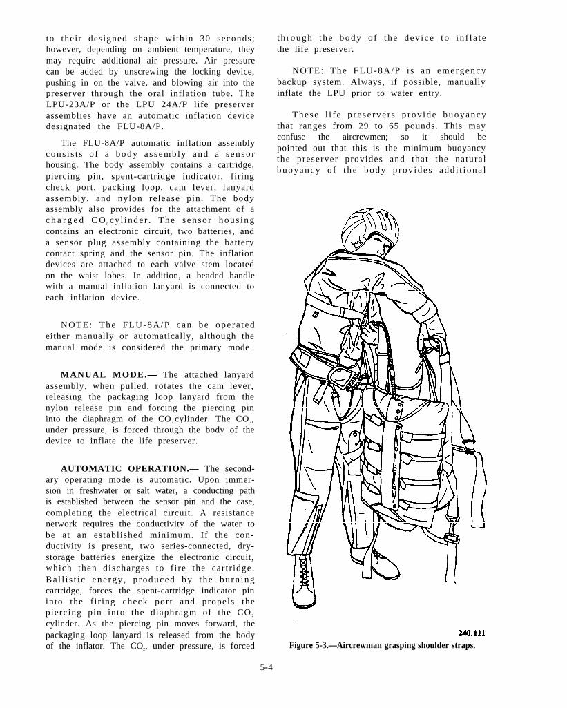
to their designed shape within 30 seconds;however, depending on ambient temperature, theymay require additional air pressure. Air pressurecan be added by unscrewing the locking device,pushing in on the valve, and blowing air into thepreserver through the oral inflation tube. TheLPU-23A/P or the LPU 24A/P life preserverassemblies have an automatic inflation devicedesignated the FLU-8A/P.
The FLU-8A/P automatic inflation assemblyc o n s i s t s o f a b o d y a s s e m b l y a n d a s e n s o rhousing. The body assembly contains a cartridge,piercing pin, spent-cartridge indicator, firingcheck port, packing loop, cam lever, lanyardassembly, and nylon release pin. The bodyassembly also provides for the attachment of ac h a r g e d C O2 c y l i n d e r . T h e s e n s o r h o u s i n gcontains an electronic circuit, two batteries, anda sensor plug assembly containing the batterycontact spring and the sensor pin. The inflationdevices are attached to each valve stem locatedon the waist lobes. In addition, a beaded handlewith a manual inflation lanyard is connected toeach inflation device.
NOTE: The FLU-8A/P can be ope ra t edeither manually or automatically, although themanual mode is considered the primary mode.
MANUAL MODE.— The attached lanyardassembly, when pulled, rotates the cam lever,releasing the packaging loop lanyard from thenylon release pin and forcing the piercing pininto the diaphragm of the CO2 cylinder. The CO2,under pressure, is forced through the body of thedevice to inflate the life preserver.
AUTOMATIC OPERATION.— The second-ary operating mode is automatic. Upon immer-sion in freshwater or salt water, a conducting pathis established between the sensor pin and the case,completing the electrical circuit. A resistancenetwork requires the conductivity of the water tobe at an establ ished minimum. If the con-ductivity is present, two series-connected, dry-storage batteries energize the electronic circuit,which then discharges to f i re the car t r idge.Ba l l i s t i c ene rgy , p roduced by t he bu rn ingcartridge, forces the spent-cartridge indicator pininto the f i r ing check port and propels thepiercing pin into the diaphragm of the CO 2
cylinder. As the piercing pin moves forward, thepackaging loop lanyard is released from the bodyof the inflator. The CO2, under pressure, is forced
t h r o u g h t h e b o d y o f t h e d e v i c e t o i n f l a t ethe life preserver.
NOTE: The FLU-8A/P i s an emergencybackup system. Always, if possible, manuallyinflate the LPU prior to water entry.
T h e s e l i f e p r e s e r v e r s p r o v i d e b u o y a n c ythat ranges from 29 to 65 pounds. This mayconfuse the aircrewmen; so it should bepointed out that this is the minimum buoyancythe preserver provides and that the naturalb u o y a n c y o f t h e b o d y p r o v i d e s a d d i t i o n a l
Figure 5-3.—Aircrewman grasping shoulder straps.
5-4
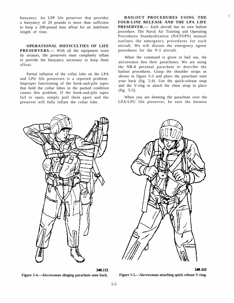
buoyancy. An LPP life preserver that providesa buoyancy of 29 pounds is more than sufficientto keep a 200-pound man afloat for an indefinitelength of time.
OPERATIONAL DIFFICULTIES OF LIFEPRESERVERS.— With all the equipment wornby aviators, life preservers must completely inflateto provide the buoyancy necessary to keep themafloat .
Partial inflation of the collar lobe on the LPAand LPU life preservers is a reported problem.Improper functioning of the hook-and-pile tapesthat hold the collar lobes in the packed conditioncauses this problem. If the hook-and-pile tapesfail to open, simply pull them apart and thepreserver will fully inflate the collar lobe.
BAILOUT PROCEDURES USING THE #
FOUR-LINE RELEASE AND THE LPA LIFEPRESERVER.— Each aircraft has its own bailoutprocedure. The Naval Air Training and OperatingProcedures Standardization (NATOPS) manualout l ines the emergency procedures for eachaircraft. We will discuss the emergency egressprocedures for the P-3 aircraft.
When the command is given to bail out, theaircrewmen don their parachutes. We are usingthe NB-8 personal parachute to describe thebailout procedures. Grasp the shoulder straps asshown in figure 5-3 and place the parachute ontoyour back (fig. 5-4). Use the quick-release snapand the V-ring to attach the chest strap in place(fig. 5-5).
When you are donning the parachute over theLPA/LPU life preserver, be sure the harness
Figure 5-4.—Aircrewman slinging parachute onto back. Figure 5-5.—Aircrewman attaching quick release V-ring.
5-5
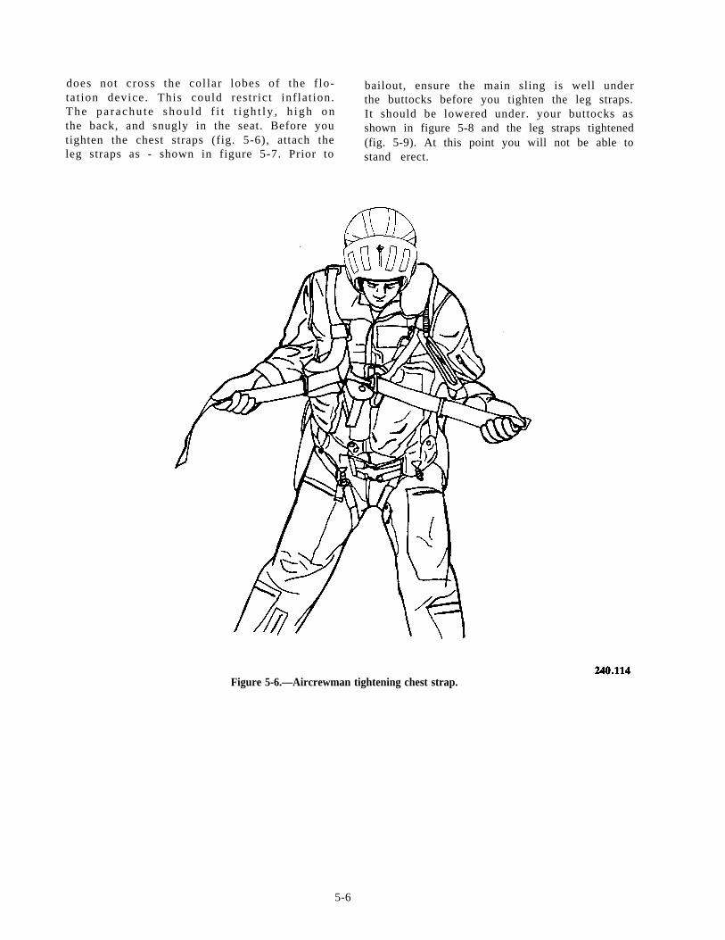
does not cross the col lar lobes of the f lo- bailout, ensure the main sling is well undertat ion device. This could restr ict inf lat ion. the buttocks before you tighten the leg straps.The pa r achu t e shou ld f i t t i gh t l y , h igh on It should be lowered under. your buttocks asthe back, and snugly in the seat. Before you shown in figure 5-8 and the leg straps tightenedtighten the chest straps (fig. 5-6), attach the (fig. 5-9). At this point you will not be able toleg straps as - shown in figure 5-7. Prior to stand erect.
Figure 5-6.—Aircrewman tightening chest strap.
5-6
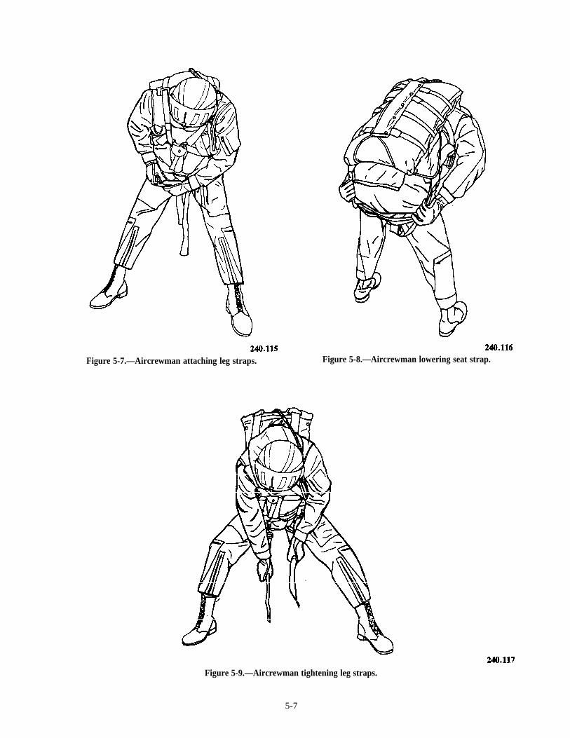
Figure 5-7.—Aircrewman attaching leg straps. Figure 5-8.—Aircrewman lowering seat strap.
Figure 5-9.—Aircrewman tightening leg straps.
5-7
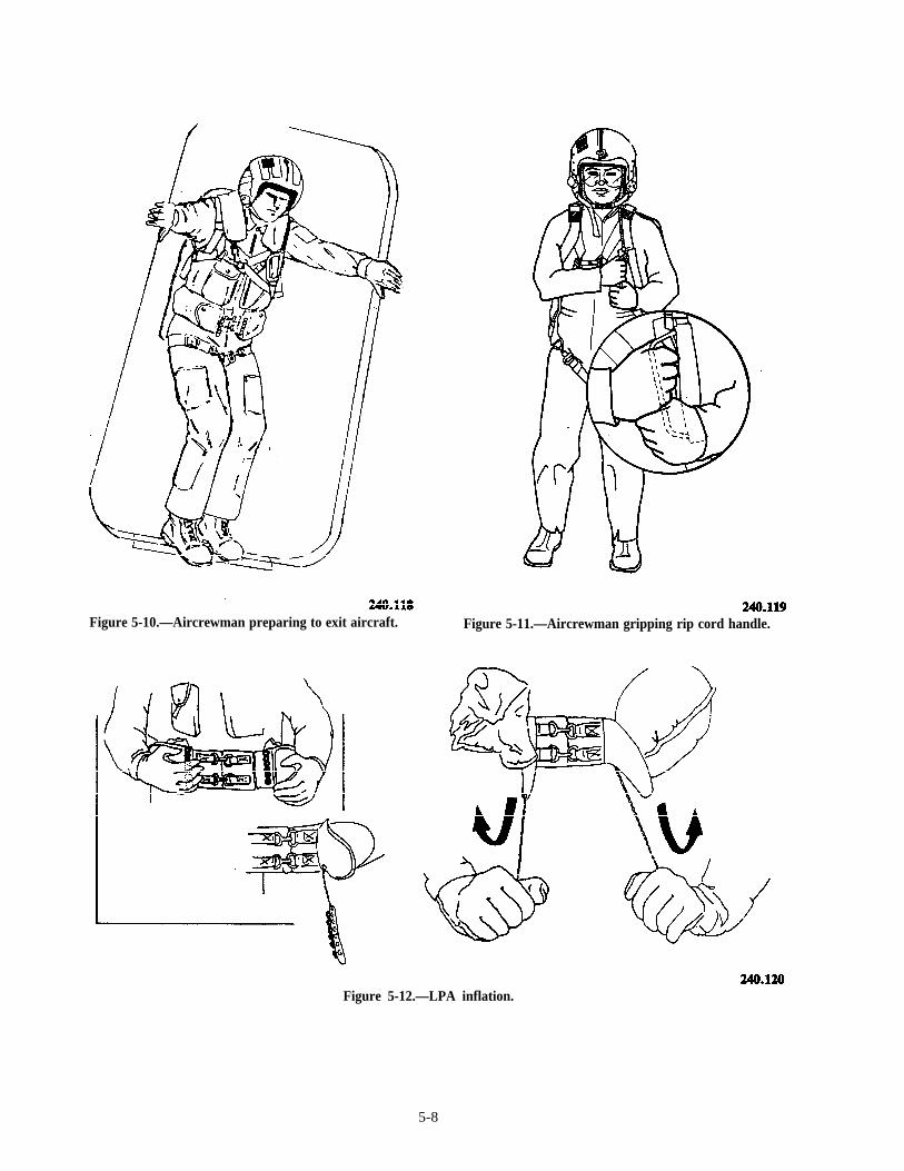
Figure 5-10.—Aircrewman preparing to exit aircraft. Figure 5-11.—Aircrewman gripping rip cord handle.
Figure 5-12.—LPA inflation.
5-8
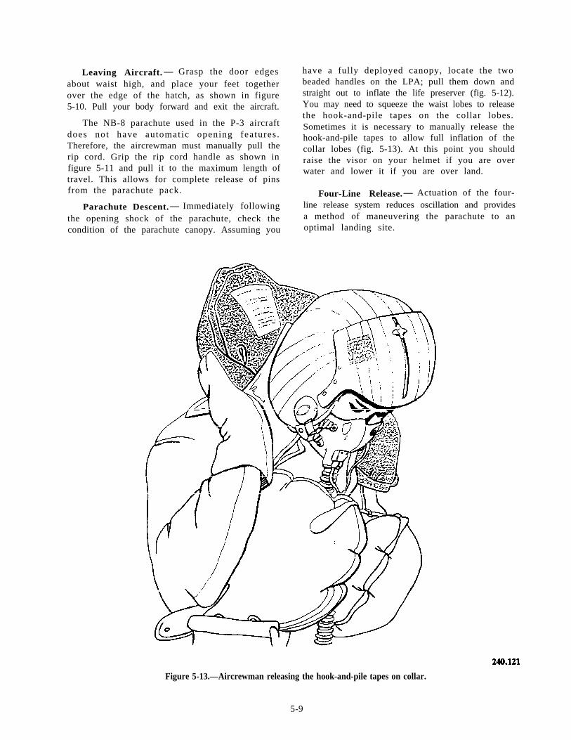
Leaving Aircraft. — Grasp the door edgesabout waist high, and place your feet togetherover the edge of the hatch, as shown in figure5-10. Pull your body forward and exit the aircraft.
The NB-8 parachute used in the P-3 aircraftdoes not have automatic opening features .Therefore, the aircrewman must manually pull therip cord. Grip the rip cord handle as shown infigure 5-11 and pull it to the maximum length oftravel. This allows for complete release of pinsfrom the parachute pack.
Parachute Descent. — Immediately followingthe opening shock of the parachute, check thecondition of the parachute canopy. Assuming you
have a fully deployed canopy, locate the twobeaded handles on the LPA; pull them down andstraight out to inflate the life preserver (fig. 5-12).You may need to squeeze the waist lobes to releasethe hook-and-pile tapes on the collar lobes.Sometimes it is necessary to manually release thehook-and-pile tapes to allow full inflation of thecollar lobes (fig. 5-13). At this point you shouldraise the visor on your helmet if you are overwater and lower it if you are over land.
Four-Line Release. — Actuation of the four-line release system reduces oscillation and providesa method of maneuvering the parachute to anoptimal landing site.
Figure 5-13.—Aircrewman releasing the hook-and-pile tapes on collar.
5-9
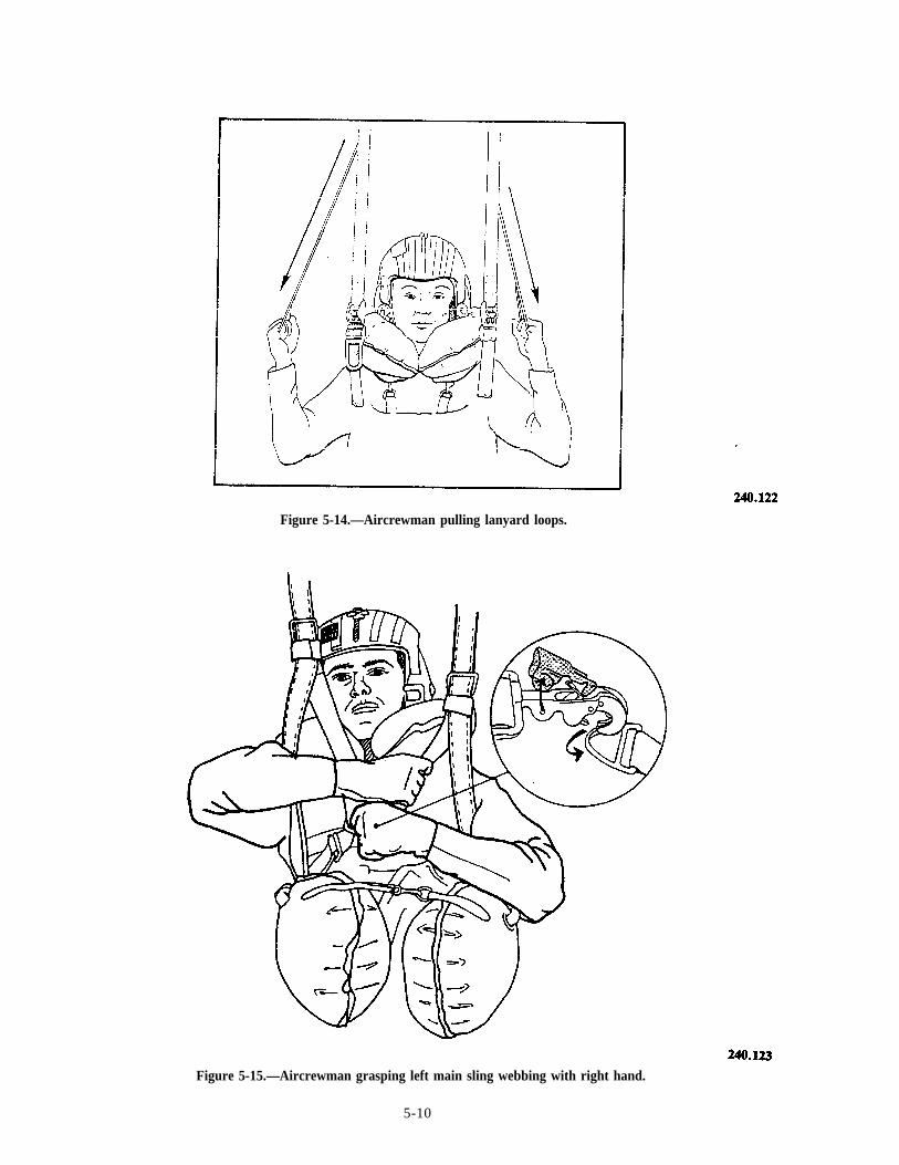
Figure 5-14.—Aircrewman pulling lanyard loops.
Figure 5-15.—Aircrewman grasping left main sling webbing with right hand.
5-10
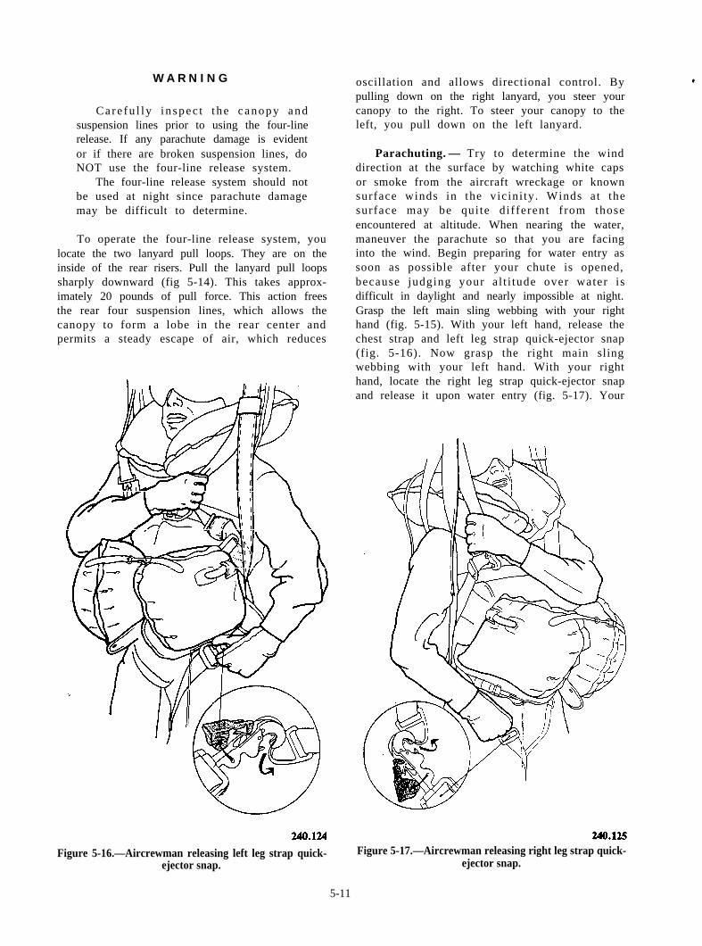
W A R N I N G
Care fu l l y i n spec t t he canopy andsuspension lines prior to using the four-linerelease. If any parachute damage is evidentor if there are broken suspension lines, doNOT use the four-line release system.
The four-line release system should notbe used at night since parachute damagemay be difficult to determine.
To operate the four-line release system, youlocate the two lanyard pull loops. They are on theinside of the rear risers. Pull the lanyard pull loopssharply downward (fig 5-14). This takes approx-imately 20 pounds of pull force. This action freesthe rear four suspension lines, which allows thecanopy to form a lobe in the rear center andpermits a steady escape of air, which reduces
Figure 5-16.—Aircrewman releasing left leg strap quick-ejector snap.
oscillation and allows directional control. Bypulling down on the right lanyard, you steer yourcanopy to the right. To steer your canopy to theleft, you pull down on the left lanyard.
Parachuting. — Try to determine the winddirection at the surface by watching white capsor smoke from the aircraft wreckage or knownsurface winds in the vicini ty . Winds at thesurface may be qui te different f rom thoseencountered at altitude. When nearing the water,maneuver the parachute so that you are facinginto the wind. Begin preparing for water entry assoon as possible after your chute is opened,because judging your a l t i tude over water isdifficult in daylight and nearly impossible at night.Grasp the left main sling webbing with your righthand (fig. 5-15). With your left hand, release thechest strap and left leg strap quick-ejector snap(fig. 5-16). Now grasp the right main slingwebbing with your left hand. With your righthand, locate the right leg strap quick-ejector snapand release it upon water entry (fig. 5-17). Your
Figure 5-17.—Aircrewman releasing right leg strap quick-ejector snap.
5-11
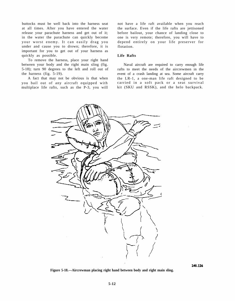
buttocks must be well back into the harness seatat all times. After you have entered the waterrelease your parachute harness and get out of it;in the water the parachute can quickly becomey o u r w o r s t e n e m y . I t c a n e a s i l y d r a g y o uunder and cause you to drown; therefore, it isimportant for you to get out of your harness asquickly as possible.
To remove the harness, place your right handbetween your body and the right main sling (fig.5-18); turn 90 degrees to the left and roll out ofthe harness (fig. 5-19).
A fact that may not be obvious is that whenyou bai l out of any aircraf t equipped withmultiplace life rafts, such as the P-3, you will
not have a life raft available when you reachthe surface. Even if the life rafts are jettisonedbefore bailout, your chance of landing close toone is very remote; therefore, you will have todepend ent i rely on your l i fe preserver forflotation.
Life Rafts
Naval aircraft are required to carry enough liferafts to meet the needs of the aircrewmen in theevent of a crash landing at sea. Some aircraft carrythe LR-1, a one-man life raft designed to beca r r i ed i n a so f t pack o r a s ea t su rv iva lkit (SKU and RSSK), and the helo backpack.
Figure 5-18.—Aircrewman placing right hand between body and right main sling.
5-12
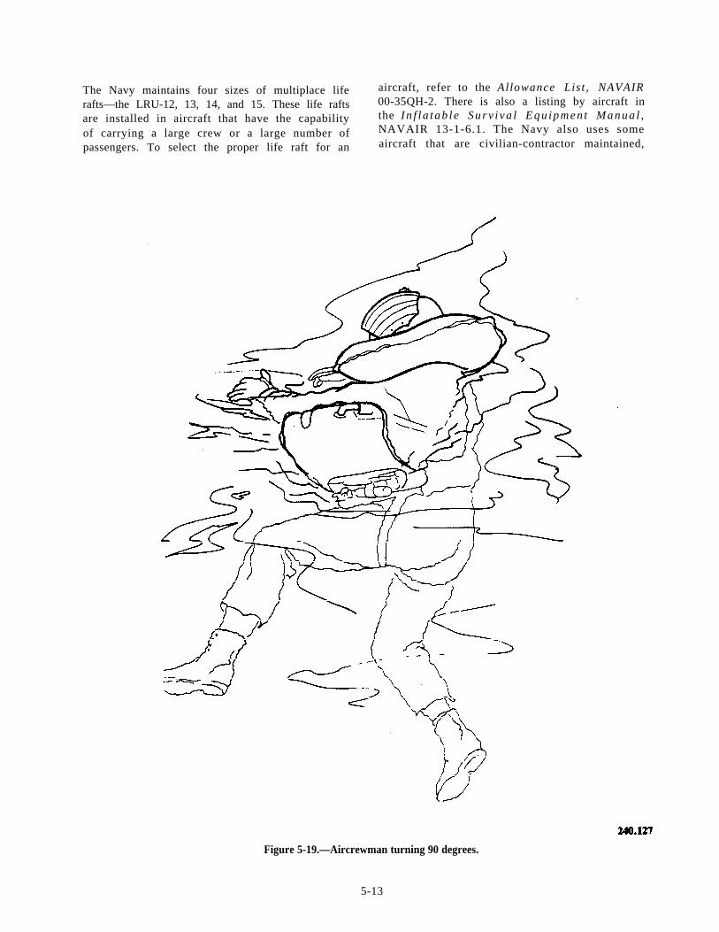
The Navy maintains four sizes of multiplace life aircraft, refer to the Allowance List , NAVAIR
rafts—the LRU-12, 13, 14, and 15. These life rafts 00-35QH-2. There is also a listing by aircraft in
are installed in aircraft that have the capability the In f l a tab l e Surv i va l Equ ipmen t Manua l ,
of carrying a large crew or a large number of NAVAIR 13-1-6.1. The Navy also uses some
passengers. To select the proper life raft for an aircraft that are civilian-contractor maintained,
Figure 5-19.—Aircrewman turning 90 degrees.
5-13
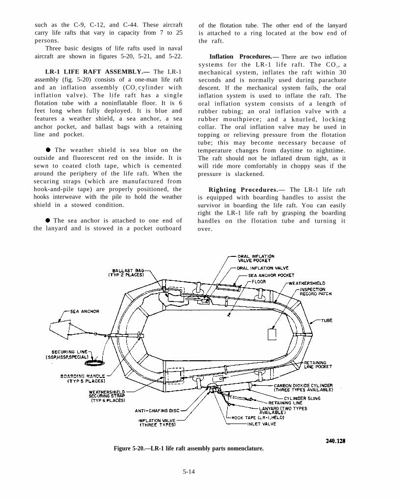
such as the C-9, C-12, and C-44. These aircraftcarry life rafts that vary in capacity from 7 to 25persons.
Three basic designs of life rafts used in navalaircraft are shown in figures 5-20, 5-21, and 5-22.
LR-1 LIFE RAFT ASSEMBLY.— The LR-1assembly (fig. 5-20) consists of a one-man life raftand an inflation assembly (CO 2 cylinder withinflat ion valve) . The l i fe raf t has a s ingleflotation tube with a noninflatable floor. It is 6feet long when fully deployed. It is blue andfeatures a weather shield, a sea anchor, a seaanchor pocket, and ballast bags with a retainingline and pocket.
. The weather shield is sea blue on theoutside and fluorescent red on the inside. It issewn to coated cloth tape, which is cementedaround the periphery of the life raft. When thesecuring straps (which are manufactured fromhook-and-pile tape) are properly positioned, thehooks interweave with the pile to hold the weathershield in a stowed condition.
. The sea anchor is attached to one end ofthe lanyard and is stowed in a pocket outboard
of the flotation tube. The other end of the lanyardis attached to a ring located at the bow end ofthe raft.
Inflation Procedures.— There are two inflationsystems for the LR-1 l i fe raft . The CO 2, amechanical system, inflates the raft within 30seconds and is normally used during parachutedescent. If the mechanical system fails, the oralinflation system is used to inflate the raft. Theoral inflation system consists of a length ofrubber tubing; an oral inflation valve with arubber mouthpiece; and a knurled, lockingcollar. The oral inflation valve may be used intopping or relieving pressure from the flotationtube; this may become necessary because oftemperature changes from daytime to nighttime.The raft should not be inflated drum tight, as itwill ride more comfortably in choppy seas if thepressure is slackened.
Righting Procedures.— The LR-1 life raftis equipped with boarding handles to assist thesurvivor in boarding the life raft. You can easilyright the LR-1 life raft by grasping the boardinghandles on the flotation tube and turning itover.
Figure 5-20.—LR-1 life raft assembly parts nomenclature.
5-14
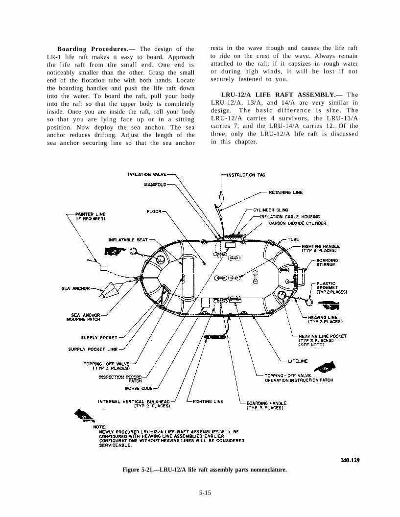
Boarding Procedures.— The design of theLR-1 life raft makes it easy to board. Approachthe life raft from the small end. One end isnoticeably smaller than the other. Grasp the smallend of the flotation tube with both hands. Locatethe boarding handles and push the life raft downinto the water. To board the raft, pull your bodyinto the raft so that the upper body is completelyinside. Once you are inside the raft, roll your bodyso that you are lying face up or in a sittingposition. Now deploy the sea anchor. The seaanchor reduces drifting. Adjust the length of thesea anchor securing line so that the sea anchor
rests in the wave trough and causes the life raftto ride on the crest of the wave. Always remainattached to the raft; if it capsizes in rough wateror during high winds, it will be lost if notsecurely fastened to you.
LRU-12/A LIFE RAFT ASSEMBLY.— TheLRU-12/A, 13/A, and 14/A are very similar indesign. The bas i c d i f f e r ence i s s i ze . TheLRU-12/A carries 4 survivors, the LRU-13/Acarries 7, and the LRU-14/A carries 12. Of thethree, only the LRU-12/A life raft is discussedin this chapter.
Figure 5-21.—LRU-12/A life raft assembly parts nomenclature.
5-15
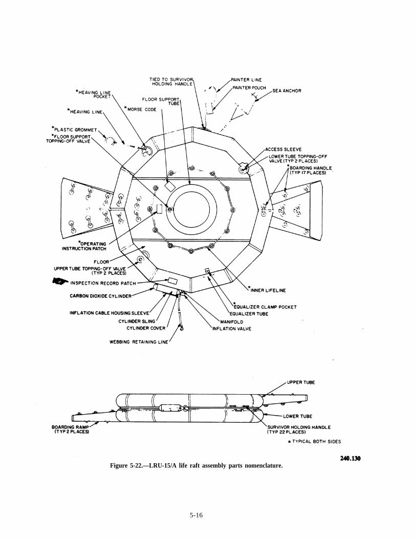
Figure 5-22.—LRU-15/A life raft assembly parts nomenclature.
5-16
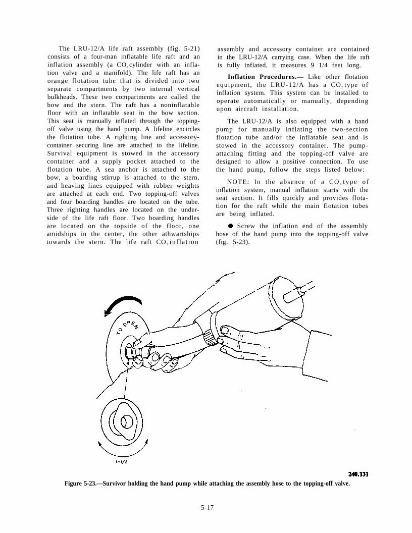
The LRU-12/A life raft assembly (fig. 5-21)consists of a four-man inflatable life raft and aninflation assembly (a CO2 cylinder with an infla-tion valve and a manifold). The life raft has anorange flotation tube that is divided into twoseparate compartments by two internal verticalbulkheads. These two compartments are called thebow and the stern. The raft has a noninflatablefloor with an inflatable seat in the bow section.This seat is manually inflated through the topping-off valve using the hand pump. A lifeline encirclesthe flotation tube. A righting line and accessory-container securing line are attached to the lifeline.Survival equipment is stowed in the accessorycontainer and a supply pocket attached to theflotation tube. A sea anchor is attached to thebow, a boarding stirrup is attached to the stern,and heaving lines equipped with rubber weightsare attached at each end. Two topping-off valvesand four boarding handles are located on the tube.Three righting handles are located on the under-side of the life raft floor. Two boarding handlesare located on the topside of the floor, oneamidships in the center, the other athwartshipstowards the stern. The life raft CO 2 i n f l a t i on
assembly and accessory container are containedin the LRU-12/A carrying case. When the life raftis fully inflated, it measures 9 1/4 feet long.
Inflation Procedures.— Like other flotationequipment, the LRU-12/A has a CO 2 type ofinflation system. This system can be installed tooperate automatically or manually, dependingupon aircraft installation.
The LRU-12/A is also equipped with a handpump for manually inflating the two-sectionflotation tube and/or the inflatable seat and isstowed in the accessory container. The pump-attaching fitting and the topping-off valve aredesigned to allow a positive connection. To usethe hand pump, follow the steps listed below:
NOTE: In the absence of a CO 2 t y p e o finflation system, manual inflation starts with theseat section. It fills quickly and provides flota-tion for the raft while the main flotation tubesare being inflated.
l Screw the inflation end of the assemblyhose of the hand pump into the topping-off valve(fig. 5-23).
Figure 5-23.—Survivor holding the hand pump while attaching the assembly hose to the topping-off valve.
5-17
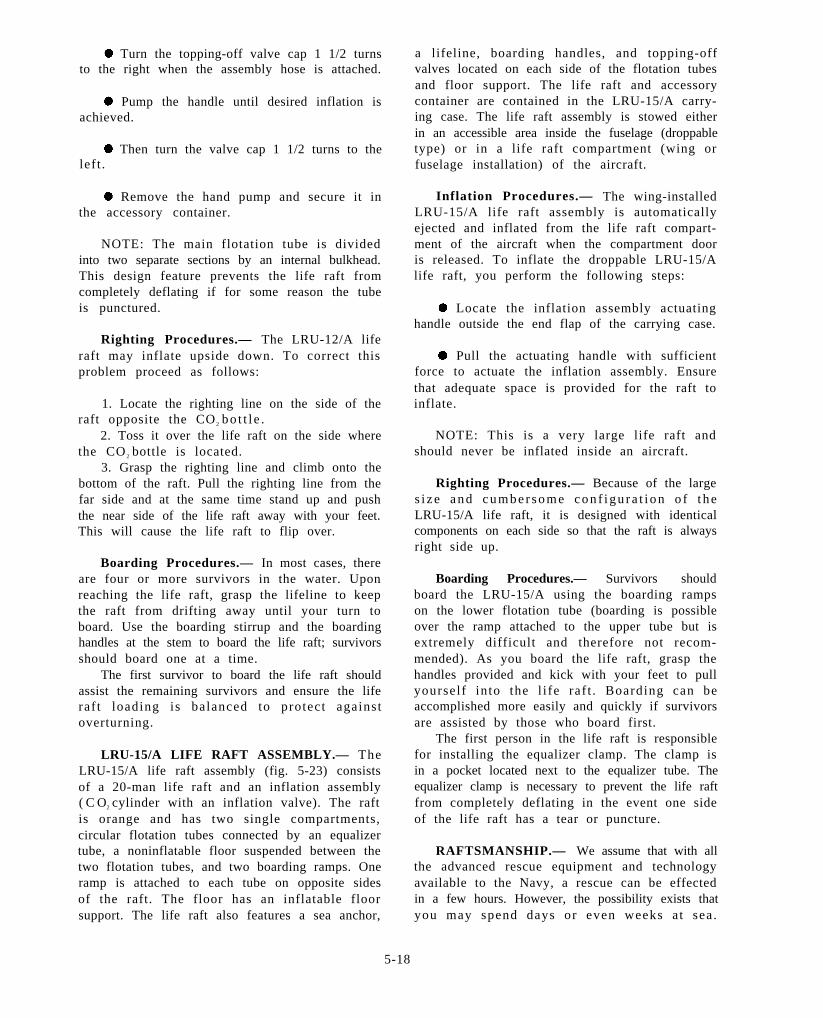
. Turn the topping-off valve cap 1 1/2 turnsto the right when the assembly hose is attached.
. Pump the handle until desired inflation isachieved.
. Then turn the valve cap 1 1/2 turns to theleft .
. Remove the hand pump and secure it inthe accessory container.
NOTE: The main flotation tube is dividedinto two separate sections by an internal bulkhead.This design feature prevents the life raft fromcompletely deflating if for some reason the tubeis punctured.
Righting Procedures.— The LRU-12/A liferaft may inflate upside down. To correct thisproblem proceed as follows:
1. Locate the righting line on the side of theraft opposite the CO 2 bo t t l e .
2. Toss it over the life raft on the side wherethe CO 2 bottle is located.
3. Grasp the righting line and climb onto thebottom of the raft. Pull the righting line from thefar side and at the same time stand up and pushthe near side of the life raft away with your feet.This will cause the life raft to flip over.
Boarding Procedures.— In most cases, thereare four or more survivors in the water. Uponreaching the life raft, grasp the lifeline to keepthe raft from drifting away until your turn toboard. Use the boarding stirrup and the boardinghandles at the stem to board the life raft; survivorsshould board one at a time.
The first survivor to board the life raft shouldassist the remaining survivors and ensure the liferaf t loading is balanced to protect againstoverturning.
LRU-15/A LIFE RAFT ASSEMBLY.— TheLRU-15/A life raft assembly (fig. 5-23) consistsof a 20-man life raft and an inflation assembly( C O2 cylinder with an inflation valve). The raftis orange and has two single compartments,circular flotation tubes connected by an equalizertube, a noninflatable floor suspended between thetwo flotation tubes, and two boarding ramps. Oneramp is attached to each tube on opposite sidesof the raft. The floor has an inflatable floorsupport. The life raft also features a sea anchor,
a lifeline, boarding handles, and topping-offvalves located on each side of the flotation tubesand floor support. The life raft and accessorycontainer are contained in the LRU-15/A carry-ing case. The life raft assembly is stowed eitherin an accessible area inside the fuselage (droppabletype) or in a life raft compartment (wing orfuselage installation) of the aircraft.
Inflation Procedures.— The wing-installedLRU-15/A life raft assembly is automaticallyejected and inflated from the life raft compart-ment of the aircraft when the compartment dooris released. To inflate the droppable LRU-15/Alife raft, you perform the following steps:
. Locate the inflation assembly actuatinghandle outside the end flap of the carrying case.
l Pull the actuating handle with sufficientforce to actuate the inflation assembly. Ensurethat adequate space is provided for the raft toinflate.
NOTE: This is a very large life raft andshould never be inflated inside an aircraft.
Righting Procedures.— Because of the larges i z e a n d c u m b e r s o m e c o n f i g u r a t i o n o f t h eLRU-15/A life raft, it is designed with identicalcomponents on each side so that the raft is alwaysright side up.
Boarding Procedures.— Survivors shouldboard the LRU-15/A using the boarding rampson the lower flotation tube (boarding is possibleover the ramp attached to the upper tube but isextremely difficult and therefore not recom-mended). As you board the life raft, grasp thehandles provided and kick with your feet to pullyourself into the l i fe raf t . Boarding can beaccomplished more easily and quickly if survivorsare assisted by those who board first.
The first person in the life raft is responsiblefor installing the equalizer clamp. The clamp isin a pocket located next to the equalizer tube. Theequalizer clamp is necessary to prevent the life raftfrom completely deflating in the event one sideof the life raft has a tear or puncture.
RAFTSMANSHIP.— We assume that with allthe advanced rescue equipment and technologyavailable to the Navy, a rescue can be effectedin a few hours. However, the possibility exists thatyou may spend days or even weeks a t sea .
5-18
Common sense is the best survival tool you willhave aboard the life raft. The following dos anddon’ts will help you survive in a life raft at sea.
Dos.— The following are helpful things to dowhile you are trying to survive in a life raft at sea:
l Stow all sharp objects and equipment thatmight abrade or puncture the raft fabric.
. Ensure all survival equipment is tied to thel ife raft . This prevents loss i f any i tem isdropped over the side.
. Secure yourself and other survivors to theraft, in case it capsizes. Rough water or a strongwind can easily separate a raft from a survivor.
l Ration al l food and water . Rationingshould be based on the minimum amount of foodand water that will sustain life.
. Inventory all supplies daily.
. Take every precaution to prevent the liferaft from turning over.
. Sit low in the life raft and distribute theweight to hold the weather side down.
l If there is more than one life raft, tie themtogether. When tieing life rafts together, youshould tie the first life raft at the stern and thesecond one to the bow. Since the LRU-15/A hasno bow or stem, tie them together at any availablepoint. If there are more than two LRU-15/A liferafts, the ties should be 180 degrees apart on thecenter raft.
l Allow approximately 25 feet of l inebetween the life rafts; adjust the length of the lineto correspond with the state of the sea.
l Adjust the sea anchor line so that the seaanchor will stay in the trough when the raft is atthe crest of a wave.
l In very rough weather, keep a spare seaanchor rigged and ready for instant use in casethe one that is deployed breaks loose. A spare seaanchor will have to be improvised as no spare isfurnished; however, a paulin, casualty blanket,or signal panel can be used for this purpose.
. Be prepared to catch any rainfall, becausewater is essential to survival at sea.
Don’ts. — The following are some things thatyou should not do while trying to survive in a liferaft at sea:
. Never eat any food unless an adequateamount of freshwater is available. The reason isthat digestion depletes the body’s fluid level. Aperson in relatively good physical condition cansurvive only about 6 days without water but cansurvive up to 40 days without food.
. Never drink seawater; it will cause nauseaand vomiting, which further depletes the body’swater level, and will eventually cause death.Seawater will not quench your thirst; it willincrease your thirst.
l When fishing never tie your fishing line tothe side of the life raft. A large fish can capsizeyour life raft.
l Never tie your fish catch to the life raft.You are inviting a larger fish to a meal.
. When you are using the Mk 13 day/nightdistress signal, never hold it near your life raft.The burning material will drip and can burn a holein the flotation tube or the floor of the liferaf t .
. Avoid unnecessary moving around insidethe life raft.
These are just a few dos and don’ts. By usingcommon sense you will be able to add to thislist.
Rafting Ashore. — Going ashore in a strongsurf is dangerous. Take your time. Select thelanding point carefully. Try not to land when thesun is low and straight in front of you. Try to landon the lee side of an island or on a point of land.Keep your eyes open for gaps in the surf line andhead for them. Avoid coral reefs and rocky cliffs.Coral reefs do not occur near the mouths offreshwater streams. Avoid rip currents or strongtidal currents, which may carry you far out to sea.Either signal shore for help or sail around andlook for a sloping beach where the surf is gentle.
If you must go through surf to reach shore,keep your clothes and shoes on to avoid severecuts. Adjust and inflate your life vest. Trail
5-19
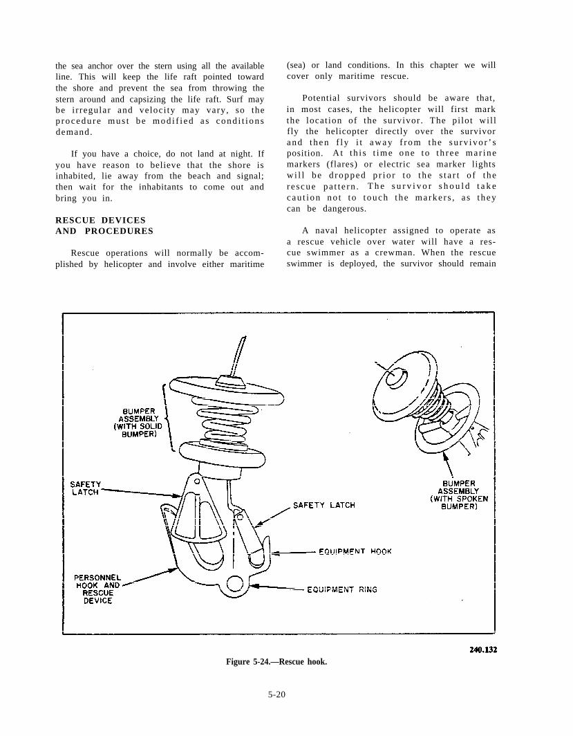
the sea anchor over the stern using all the availableline. This will keep the life raft pointed towardthe shore and prevent the sea from throwing thestern around and capsizing the life raft. Surf maybe i r regular and veloci ty may vary, so thep r o c e d u r e m u s t b e m o d i f i e d a s c o n d i t i o n sdemand.
If you have a choice, do not land at night. Ifyou have reason to believe that the shore isinhabited, lie away from the beach and signal;then wait for the inhabitants to come out andbring you in.
RESCUE DEVICESAND PROCEDURES
Rescue operations will normally be accom-plished by helicopter and involve either maritime
(sea) or land conditions. In this chapter we willcover only maritime rescue.
Potential survivors should be aware that,in most cases, the helicopter will first markthe locat ion of the survivor . The pi lot wil lfly the helicopter directly over the survivora n d t h e n f l y i t a w a y f r o m t h e s u r v i v o r ’ sposition. A t t h i s t ime one to t h r ee mar inemarkers (flares) or electric sea marker lightsw i l l be d ropped p r i o r t o t he s t a r t o f t here scue pa t t e rn . T h e s u r v i v o r s h o u l d t a k ecau t ion no t t o t ouch t he marke r s , a s t heycan be dangerous.
A naval helicopter assigned to operate asa rescue vehicle over water will have a res-cue swimmer as a crewman. When the rescueswimmer is deployed, the survivor should remain
Figure 5-24.—Rescue hook.
5-20
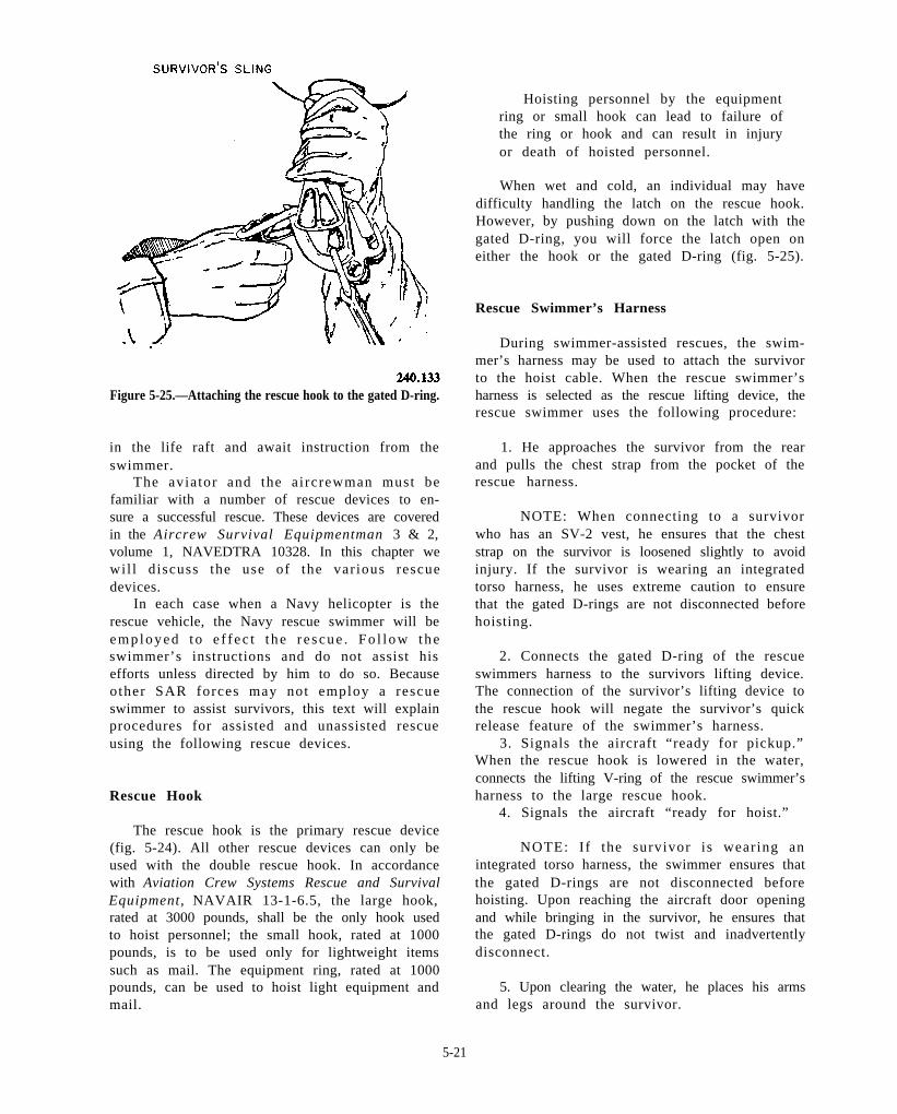
Figure 5-25.—Attaching the rescue hook to the gated D-ring.
in the life raft and await instruction from theswimmer.
The aviator and the aircrewman must befamiliar with a number of rescue devices to en-sure a successful rescue. These devices are coveredin the Aircrew Survival Equipmentman 3 & 2,volume 1, NAVEDTRA 10328. In this chapter wewil l discuss the use of the var ious rescuedevices.
In each case when a Navy helicopter is therescue vehicle, the Navy rescue swimmer will beemployed t o e f f ec t t he r e scue . Fo l low theswimmer’s instructions and do not assist hisefforts unless directed by him to do so. Becauseother SAR forces may not employ a rescueswimmer to assist survivors, this text will explainprocedures for assisted and unassisted rescueusing the following rescue devices.
Rescue Hook
The rescue hook is the primary rescue device(fig. 5-24). All other rescue devices can only beused with the double rescue hook. In accordancewith Aviation Crew Systems Rescue and SurvivalEquipment, NAVAIR 13-1-6.5, the large hook,rated at 3000 pounds, shall be the only hook usedto hoist personnel; the small hook, rated at 1000pounds, is to be used only for lightweight itemssuch as mail. The equipment ring, rated at 1000pounds, can be used to hoist light equipment andmail.
Hoisting personnel by the equipmentring or small hook can lead to failure ofthe ring or hook and can result in injuryor death of hoisted personnel.
When wet and cold, an individual may havedifficulty handling the latch on the rescue hook.However, by pushing down on the latch with thegated D-ring, you will force the latch open oneither the hook or the gated D-ring (fig. 5-25).
Rescue Swimmer’s Harness
During swimmer-assisted rescues, the swim-mer’s harness may be used to attach the survivorto the hoist cable. When the rescue swimmer’sharness is selected as the rescue lifting device, therescue swimmer uses the following procedure:
1. He approaches the survivor from the rearand pulls the chest strap from the pocket of therescue harness.
NOTE: When connecting to a survivorwho has an SV-2 vest, he ensures that the cheststrap on the survivor is loosened slightly to avoidinjury. If the survivor is wearing an integratedtorso harness, he uses extreme caution to ensurethat the gated D-rings are not disconnected beforehoisting.
2. Connects the gated D-ring of the rescueswimmers harness to the survivors lifting device.The connection of the survivor’s lifting device tothe rescue hook will negate the survivor’s quickrelease feature of the swimmer’s harness.
3. Signals the aircraft “ready for pickup.”When the rescue hook is lowered in the water,connects the lifting V-ring of the rescue swimmer’sharness to the large rescue hook.
4. Signals the aircraft “ready for hoist.”
NOTE: If the survivor is wearing anintegrated torso harness, the swimmer ensures thatthe gated D-rings are not disconnected beforehoisting. Upon reaching the aircraft door openingand while bringing in the survivor, he ensures thatthe gated D-rings do not twist and inadvertentlydisconnect.
5. Upon clearing the water, he places his armsand legs around the survivor.
5-21
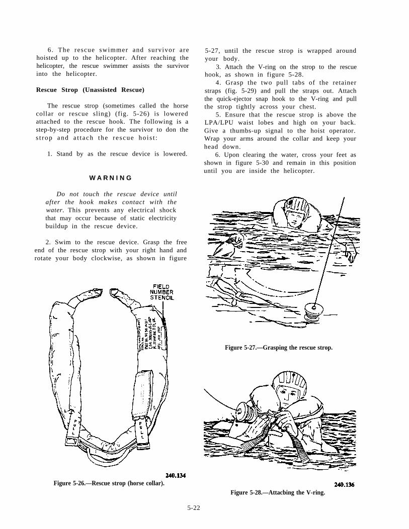
6. The rescue swimmer and survivor arehoisted up to the helicopter. After reaching thehelicopter, the rescue swimmer assists the survivorinto the helicopter.
Rescue Strop (Unassisted Rescue)
The rescue strop (sometimes called the horsecollar or rescue sling) (fig. 5-26) is loweredattached to the rescue hook. The following is astep-by-step procedure for the survivor to don thes t rop and a t t a ch t he r e scue ho i s t :
1. Stand by as the rescue device is lowered.
W A R N I N G
Do not touch the rescue device untilafter the hook makes contact with thewater. This prevents any electrical shockthat may occur because of static electricitybuildup in the rescue device.
2. Swim to the rescue device. Grasp the freeend of the rescue strop with your right hand androtate your body clockwise, as shown in figure
Figure 5-26.—Rescue strop (horse collar).
5-27, until the rescue strop is wrapped aroundyour body.
3. Attach the V-ring on the strop to the rescuehook, as shown in figure 5-28.
4. Grasp the two pull tabs of the retainerstraps (fig. 5-29) and pull the straps out. Attachthe quick-ejector snap hook to the V-ring and pullthe strop tightly across your chest.
5. Ensure that the rescue strop is above theLPA/LPU waist lobes and high on your back.Give a thumbs-up signal to the hoist operator.Wrap your arms around the collar and keep yourhead down.
6. Upon clearing the water, cross your feet asshown in figure 5-30 and remain in this positionuntil you are inside the helicopter.
Figure 5-27.—Grasping the rescue strop.
Figure 5-28.—Attacbing the V-ring.
5-22
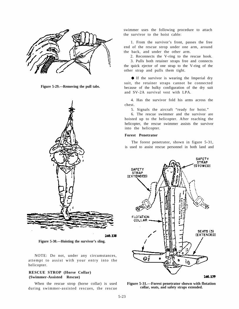
Figure 5-29.—Removing the pull tabs.
Figure 5-30.—Hoisting the survivor’s sling.
NOTE: Do not, under any circumstances,a t t emp t t o a s s i s t w i th you r en t ry i n to t hehelicopter.
RESCUE STROP (Horse Collar)(Swimmer-Assisted Rescue)
When the rescue strop (horse collar) is usedduring swimmer-assis ted rescues, the rescue
swimmer uses the following procedure to attachthe survivor to the hoist cable:
1. From the survivor’s front, passes the freeend of the rescue strop under one arm, aroundthe back, and under the other arm.
2. Reconnects the V-ring to the rescue hook.3. Pulls both retainer straps free and connects
the quick ejector of one strap to the V-ring of theother strap and pulls them tight.
. If the survivor is wearing the Imperial drysuit, the retainer straps cannot be connectedbecause of the bulky configuration of the dry suitand SV-2A survival vest with LPA.
4. Has the survivor fold his arms across thechest.
5. Signals the aircraft “ready for hoist.”6. The rescue swimmer and the survivor are
hoisted up to the helicopter. After reaching thehelicopter, the rescue swimmer assists the survivorinto the helicopter.
Forest Penetrator
The forest penetrator, shown in figure 5-31,is used to assist rescue personnel in both land and
Figure 5-31.—Forest penetrator shown with flotationcollar, seats, and safety straps extended.
5-23
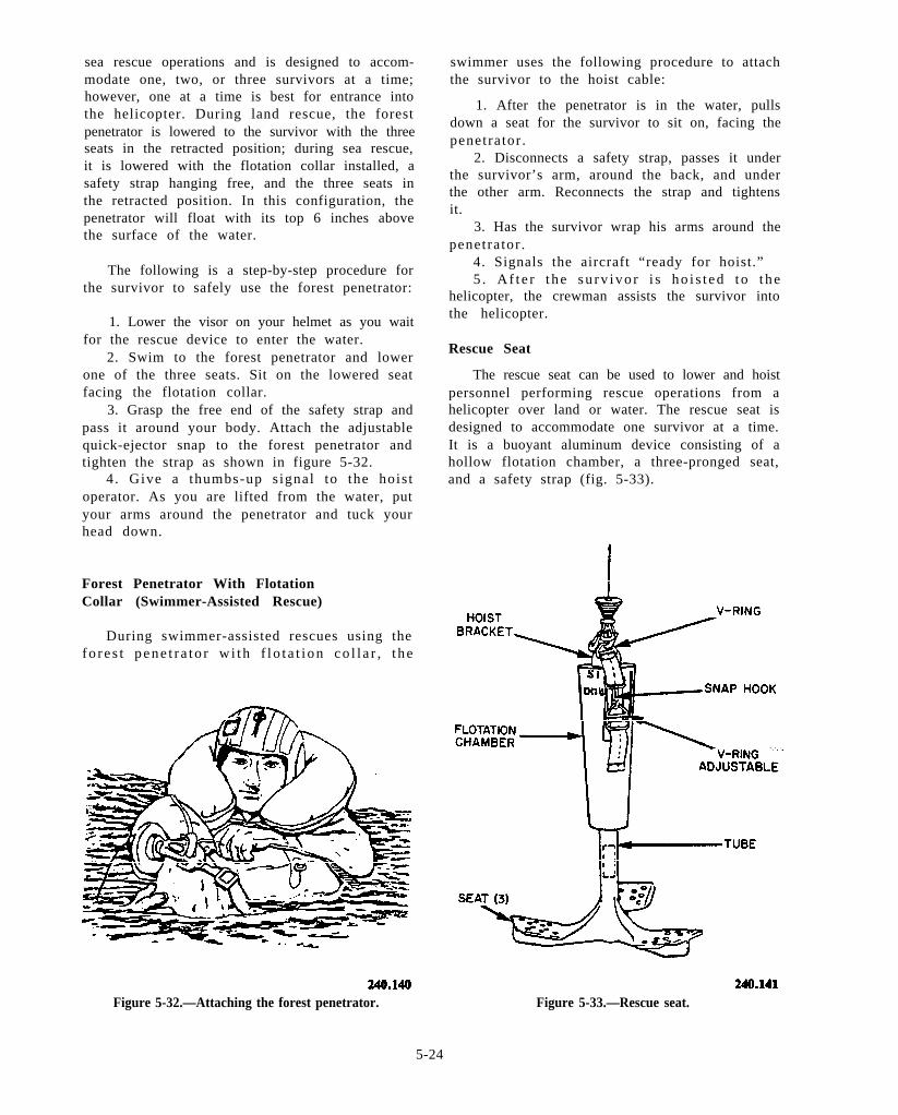
sea rescue operations and is designed to accom-modate one, two, or three survivors at a time;however, one at a time is best for entrance intothe helicopter. During land rescue, the forestpenetrator is lowered to the survivor with the threeseats in the retracted position; during sea rescue,it is lowered with the flotation collar installed, asafety strap hanging free, and the three seats inthe retracted position. In this configuration, thepenetrator will float with its top 6 inches abovethe surface of the water.
The following is a step-by-step procedure forthe survivor to safely use the forest penetrator:
1. Lower the visor on your helmet as you waitfor the rescue device to enter the water.
2. Swim to the forest penetrator and lowerone of the three seats. Sit on the lowered seatfacing the flotation collar.
3. Grasp the free end of the safety strap andpass it around your body. Attach the adjustablequick-ejector snap to the forest penetrator andtighten the strap as shown in figure 5-32.
4. Give a thumbs-up s ignal to the hois toperator. As you are lifted from the water, putyour arms around the penetrator and tuck yourhead down.
Forest Penetrator With FlotationCollar (Swimmer-Assisted Rescue)
During swimmer-assisted rescues using thefo re s t pene t r a to r w i th f l o t a t i on co l l a r , t he
Figure 5-32.—Attaching the forest penetrator.
swimmer uses the following procedure to attachthe survivor to the hoist cable:
1. After the penetrator is in the water, pullsdown a seat for the survivor to sit on, facing thepenetrator .
2. Disconnects a safety strap, passes it underthe survivor’s arm, around the back, and underthe other arm. Reconnects the strap and tightensit.
3. Has the survivor wrap his arms around thepenetrator .
4. Signals the aircraft “ready for hoist.”5 . Af t e r t he su rv ivo r i s ho i s t ed t o t he
helicopter, the crewman assists the survivor intothe helicopter.
Rescue Seat
The rescue seat can be used to lower and hoistpersonnel performing rescue operations from ahelicopter over land or water. The rescue seat isdesigned to accommodate one survivor at a time.It is a buoyant aluminum device consisting of ahollow flotation chamber, a three-pronged seat,and a safety strap (fig. 5-33).
Figure 5-33.—Rescue seat.
5-24
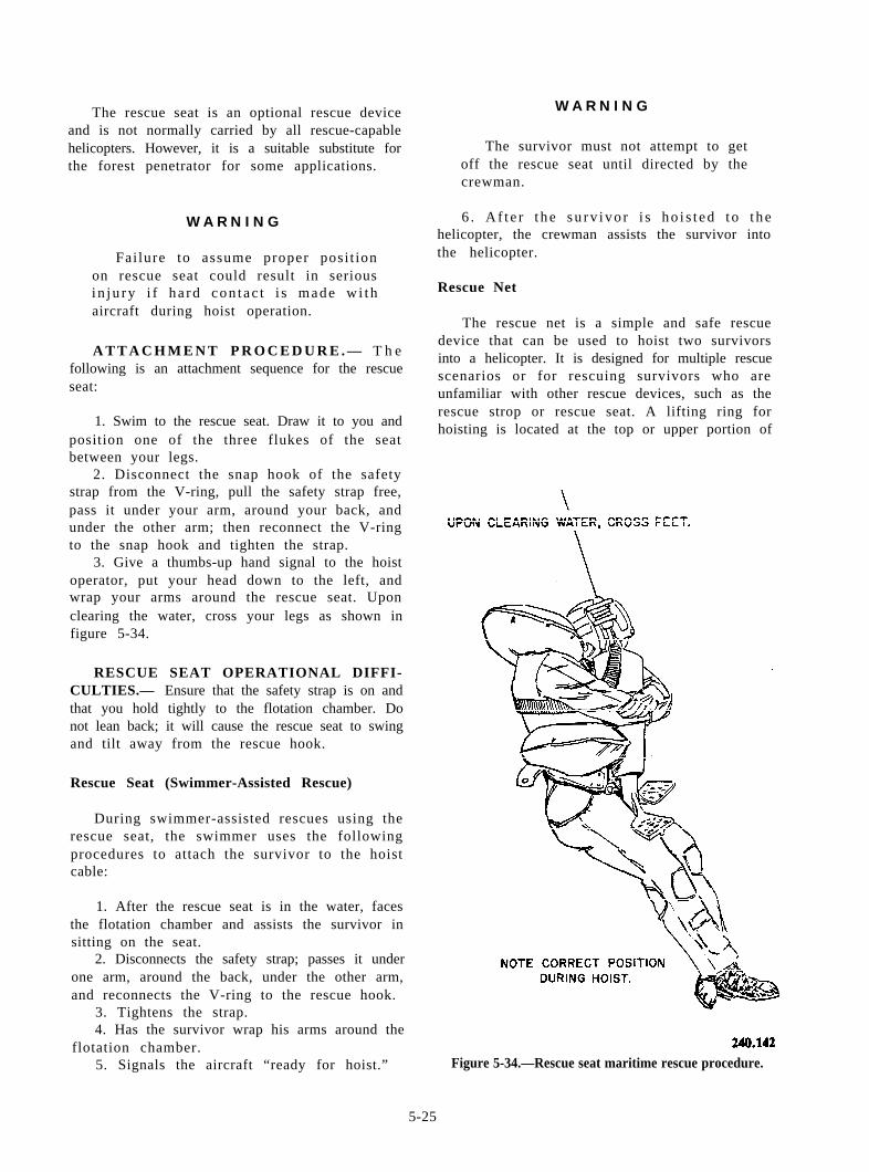
The rescue seat is an optional rescue deviceand is not normally carried by all rescue-capablehelicopters. However, it is a suitable substitute forthe forest penetrator for some applications.
W A R N I N G
W A R N I N G
Failure to assume proper posi t ionon rescue seat could result in seriousin ju ry i f ha rd con t ac t i s made w i thaircraft during hoist operation.
A T T A C H M E N T P R O C E D U R E . — T h efollowing is an attachment sequence for the rescueseat:
1. Swim to the rescue seat. Draw it to you andposition one of the three flukes of the seatbetween your legs.
2. Disconnect the snap hook of the safetystrap from the V-ring, pull the safety strap free,pass it under your arm, around your back, andunder the other arm; then reconnect the V-ringto the snap hook and tighten the strap.
3. Give a thumbs-up hand signal to the hoistoperator, put your head down to the left, andwrap your arms around the rescue seat. Uponclearing the water, cross your legs as shown infigure 5-34.
RESCUE SEAT OPERATIONAL DIFFI-CULTIES.— Ensure that the safety strap is on andthat you hold tightly to the flotation chamber. Donot lean back; it will cause the rescue seat to swingand tilt away from the rescue hook.
Rescue Seat (Swimmer-Assisted Rescue)
During swimmer-assisted rescues using therescue seat, the swimmer uses the followingprocedures to attach the survivor to the hoistcable:
1. After the rescue seat is in the water, facesthe flotation chamber and assists the survivor insitting on the seat.
2. Disconnects the safety strap; passes it underone arm, around the back, under the other arm,and reconnects the V-ring to the rescue hook.
3. Tightens the strap.4. Has the survivor wrap his arms around the
flotation chamber.5. Signals the aircraft “ready for hoist.”
The survivor must not attempt to getoff the rescue seat until directed by thecrewman.
6 . Af t e r t he su rv ivo r i s ho i s t ed t o t hehelicopter, the crewman assists the survivor intothe helicopter.
Rescue Net
The rescue net is a simple and safe rescuedevice that can be used to hoist two survivorsinto a helicopter. It is designed for multiple rescuescenarios or for rescuing survivors who areunfamiliar with other rescue devices, such as therescue strop or rescue seat. A lifting ring forhoisting is located at the top or upper portion of
Figure 5-34.—Rescue seat maritime rescue procedure.
5-25
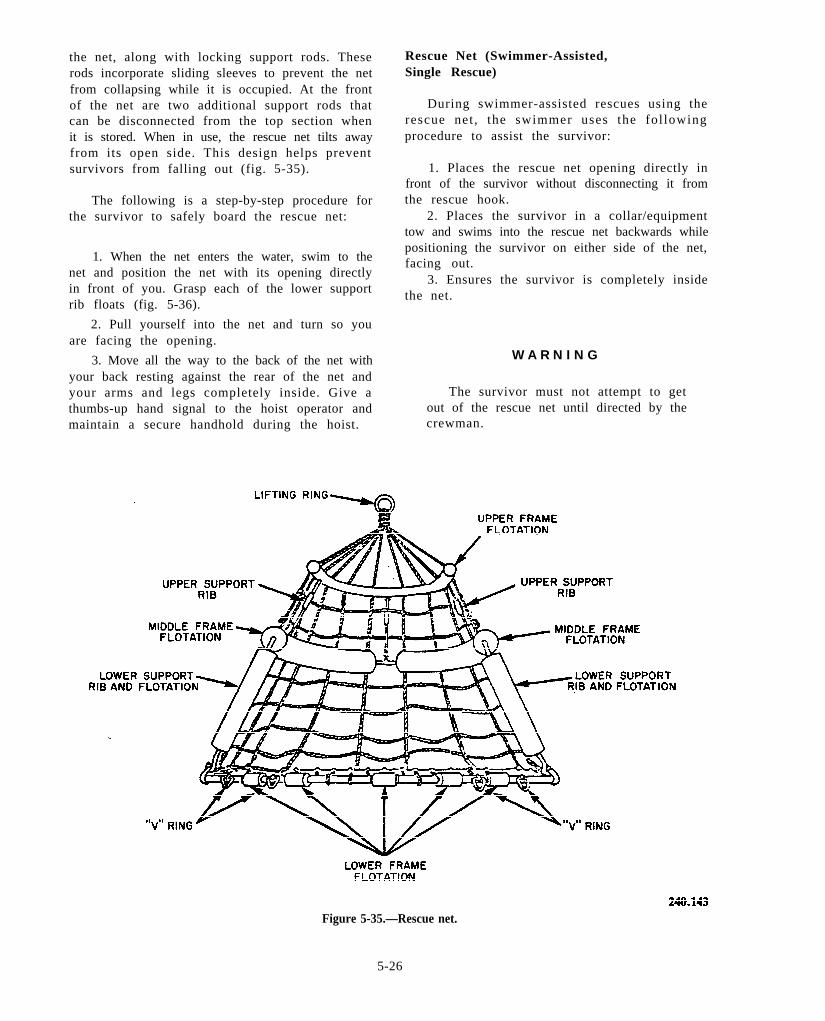
the net, along with locking support rods. Theserods incorporate sliding sleeves to prevent the netfrom collapsing while it is occupied. At the frontof the net are two additional support rods thatcan be disconnected from the top section whenit is stored. When in use, the rescue net tilts awayfrom its open side. This design helps preventsurvivors from falling out (fig. 5-35).
The following is a step-by-step procedure forthe survivor to safely board the rescue net:
1. When the net enters the water, swim to thenet and position the net with its opening directlyin front of you. Grasp each of the lower supportrib floats (fig. 5-36).
2. Pull yourself into the net and turn so youare facing the opening.
3. Move all the way to the back of the net withyour back resting against the rear of the net andyour arms and legs completely inside. Give athumbs-up hand signal to the hoist operator andmaintain a secure handhold during the hoist.
Rescue Net (Swimmer-Assisted,Single Rescue)
During swimmer-assisted rescues using therescue net , the swimmer uses the fol lowingprocedure to assist the survivor:
1. Places the rescue net opening directly infront of the survivor without disconnecting it fromthe rescue hook.
2. Places the survivor in a collar/equipmenttow and swims into the rescue net backwards whilepositioning the survivor on either side of the net,facing out.
3. Ensures the survivor is completely insidethe net.
W A R N I N G
The survivor must not attempt to getout of the rescue net until directed by thecrewman.
Figure 5-35.—Rescue net.
5-26
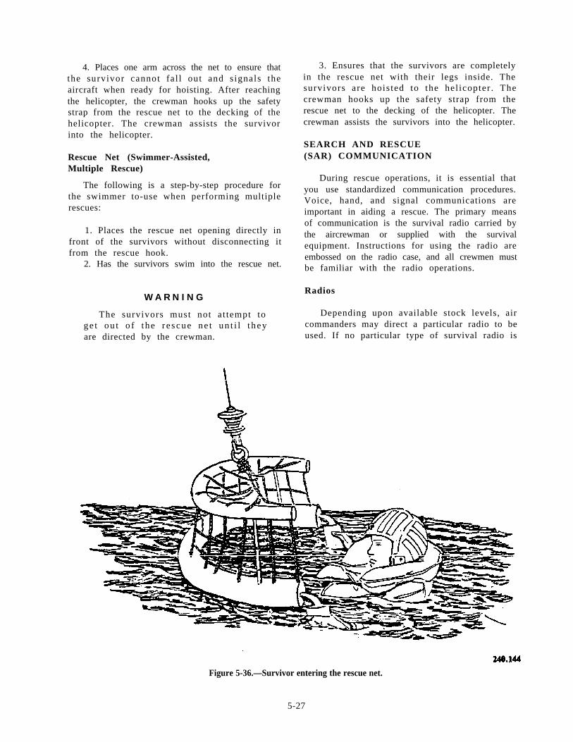
4. Places one arm across the net to ensure thatthe survivor cannot fa l l out and s ignals theaircraft when ready for hoisting. After reachingthe helicopter, the crewman hooks up the safetystrap from the rescue net to the decking of thehelicopter. The crewman assists the survivorinto the helicopter.
Rescue Net (Swimmer-Assisted,Multiple Rescue)
The following is a step-by-step procedure forthe swimmer to-use when performing multiplerescues:
1. Places the rescue net opening directly infront of the survivors without disconnecting itfrom the rescue hook.
2. Has the survivors swim into the rescue net.
W A R N I N G
The survivors must not at tempt toge t ou t o f t he r e scue ne t un t i l t heyare directed by the crewman.
3. Ensures that the survivors are completelyin the rescue net with their legs inside. Thesurvivors are hois ted to the hel icopter . Thecrewman hooks up the safety strap from therescue net to the decking of the helicopter. Thecrewman assists the survivors into the helicopter.
SEARCH AND RESCUE(SAR) COMMUNICATION
During rescue operations, it is essential thatyou use standardized communication procedures.Voice, hand, and signal communications areimportant in aiding a rescue. The primary meansof communication is the survival radio carried bythe aircrewman or supplied with the survivalequipment. Instructions for using the radio areembossed on the radio case, and all crewmen mustbe familiar with the radio operations.
Radios
Depending upon available stock levels, aircommanders may direct a particular radio to beused. If no particular type of survival radio is
Figure 5-36.—Survivor entering the rescue net.
5-27

a v a i l a b l e , e a c h l i f e r a f t m u s t h a v e a nAN/URT-33A beacon or AN/PRC-90 radio set.We will cover the AN/PRT-5, AN/URT-33A,and the AN/PRC-90 survival radios in thischapter .
In addition to the automatic direction finder(ADF) capabi l i ty of SAR force aircraf t , theUnited States government also uses satellitesthat monitor guard frequencies for emergencylocator transmitter (ELT) broadcasts.
AN/PRT-5.— The AN/PRT-5 radio transmitsa tone-modulated s ignal in both high- andultrahigh-frequency ranges. The set has aninflatable collar assembly that allows it to floatat sea or sit upright on land. The radio can operatecontinuously for 72 hours at 25°C (77°F). Noprovisions for voice or code communications orfor receiving signals from search aircraft areavailable with this transmitter. The AN/PRT-5radio operates on 243.0 and 8364 MHz. Theassembly instructions and the directions for useare included with each set.
AN/URT-33A.— The AN/URT-33A beaconradio is a battery-operated radio that transmitsa tone-modulated radio s ignal . The bat teryprovides 72 hours of cont inuous operat ion.It must be pointed out that this beacon shouldnot be used at the same time the AN/PRC-90is being used, as the AN/URT-33 will inter-fere with the voice communication signal oft h e A N / P R C - 9 0 . W h e n y o u a r e u s i n g t h eAN/URT-33, do not point the antenna directlytoward the receiving aircraf t because of thetype o f an t enna emp loyed ; a con i ca l a r eaperpendicular to the antenna tip does not radiatea signal.
Do not attempt to use the telescoping antennao n t h e A N / U R T - 3 3 A r a d i o w i t h o u t f i r s tdetaching the f lexible antenna. Use of bothantennae creates interference in the transmissionpatterns of both.
To turn the AN/URT-33A radio on, youmust move the switch to a posi t ion wheret h e w o r d O N c a n b e r e a d . T h i s m a y b ec o n f u s i n g t o t h e a i r c r e w m a n , a n d t h eAN/URT-33A could be on when the aircrewmanthinks it’s OFF.
AN/PRC-90.— The AN/PRC-90 radio set isa dua l - channe l pe r sona l emergency r e scuetransceiver, used principally for two-way-voice ormodulated-continuous-wave (MCW) communica-tion between a downed aircrew member and arescue aircraf t . Provisions are included for
transmitting tone MCW and swept-frequencyhoming beacon signals to guide rescue efforts.
The AN/PRC-90 is bat tery powered andcontains a flexible antenna, an interchangeabletelescopic antenna, a function switch (knob andindicator), an MCW button for Morse code, avolume control dial, and an earphone.
When you are using the voice mode, theAN/PRC-90 is capable of transmitting up to 60nautical miles (nmi) and up to 80 nmi on beaconor code. A rule of thumb is that this and othersurvival radios are limited to a line-of-sight
Figure 5-37.—Rescue hand signals.
5-28
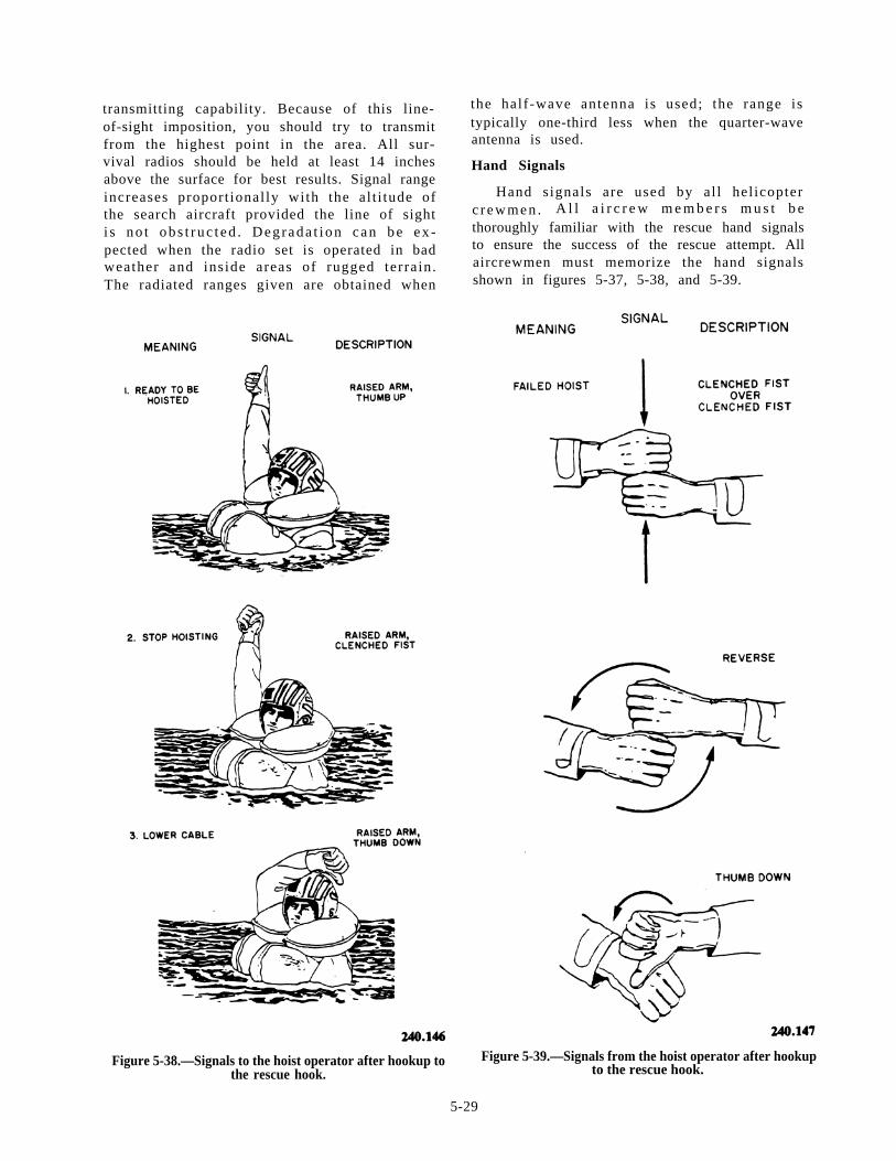
transmitting capability. Because of this line-of-sight imposition, you should try to transmitfrom the highest point in the area. All sur-vival radios should be held at least 14 inchesabove the surface for best results. Signal rangeincreases proport ional ly with the al t i tude ofthe search aircraft provided the line of sighti s no t obs t ruc t ed . Deg rada t i on can be ex -pected when the radio set is operated in badweather and inside areas of rugged terrain.The radiated ranges given are obtained when
the half-wave antenna is used; the range istypically one-third less when the quarter-waveantenna is used.
Hand Signals
Hand signals are used by al l hel icopterc r ewmen . A l l a i r c r e w m e m b e r s m u s t b ethoroughly familiar with the rescue hand signalsto ensure the success of the rescue attempt. Allaircrewmen must memorize the hand signalsshown in figures 5-37, 5-38, and 5-39.
Figure 5-38.—Signals to the hoist operator after hookup to Figure 5-39.—Signals from the hoist operator after hookupthe rescue hook. to the rescue hook.
5-29
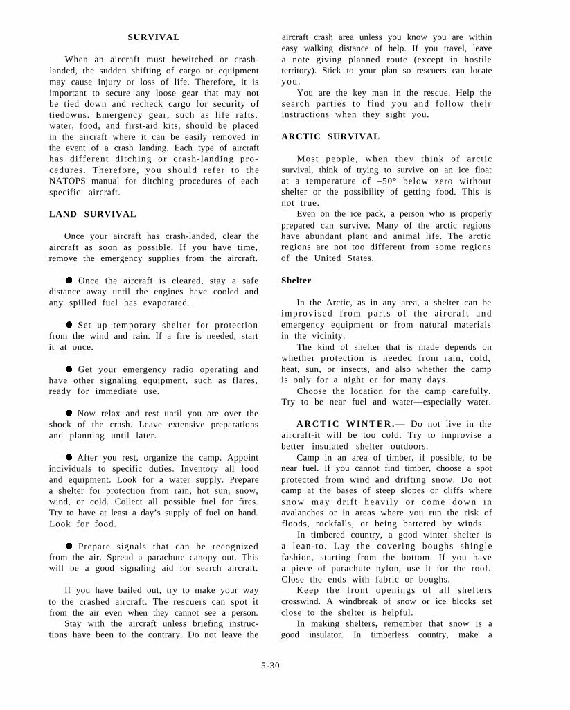
SURVIVAL
When an aircraft must bewitched or crash-landed, the sudden shifting of cargo or equipmentmay cause injury or loss of life. Therefore, it isimportant to secure any loose gear that may notbe tied down and recheck cargo for security oftiedowns. Emergency gear, such as life rafts,water, food, and first-aid kits, should be placedin the aircraft where it can be easily removed inthe event of a crash landing. Each type of aircrafthas different di tching or crash-landing pro-cedures . Therefore , you should refer to theNATOPS manual for ditching procedures of eachspecific aircraft.
LAND SURVIVAL
Once your aircraft has crash-landed, clear theaircraft as soon as possible. If you have time,remove the emergency supplies from the aircraft.
. Once the aircraft is cleared, stay a safedistance away until the engines have cooled andany spilled fuel has evaporated.
. Set up temporary shelter for protectionfrom the wind and rain. If a fire is needed, startit at once.
. Get your emergency radio operating andhave other signaling equipment, such as flares,ready for immediate use.
. Now relax and rest until you are over theshock of the crash. Leave extensive preparationsand planning until later.
. After you rest, organize the camp. Appointindividuals to specific duties. Inventory all foodand equipment. Look for a water supply. Preparea shelter for protection from rain, hot sun, snow,wind, or cold. Collect all possible fuel for fires.Try to have at least a day’s supply of fuel on hand.Look for food.
. Prepare signals that can be recognizedfrom the air. Spread a parachute canopy out. Thiswill be a good signaling aid for search aircraft.
If you have bailed out, try to make your wayto the crashed aircraft. The rescuers can spot itfrom the air even when they cannot see a person.
Stay with the aircraft unless briefing instruc-tions have been to the contrary. Do not leave the
aircraft crash area unless you know you are withineasy walking distance of help. If you travel, leavea note giving planned route (except in hostileterritory). Stick to your plan so rescuers can locateyou.
You are the key man in the rescue. Help thesearch part ies to f ind you and fol low theirinstructions when they sight you.
ARCTIC SURVIVAL
Most people , when they think of arct icsurvival, think of trying to survive on an ice floatat a temperature of –50° below zero withoutshelter or the possibility of getting food. This isnot true.
Even on the ice pack, a person who is properlyprepared can survive. Many of the arctic regionshave abundant plant and animal life. The arcticregions are not too different from some regionsof the United States.
Shelter
In the Arctic, as in any area, a shelter can beimprov i s ed f rom pa r t s o f t he a i r c r a f t andemergency equipment or from natural materialsin the vicinity.
The kind of shelter that is made depends onwhether protection is needed from rain, cold,heat, sun, or insects, and also whether the campis only for a night or for many days.
Choose the location for the camp carefully.Try to be near fuel and water—especially water.
A R C T I C W I N T E R . — Do not live in theaircraft-it will be too cold. Try to improvise abetter insulated shelter outdoors.
Camp in an area of timber, if possible, to benear fuel. If you cannot find timber, choose a spotprotected from wind and drifting snow. Do notcamp at the bases of steep slopes or cliffs wheres n o w m a y d r i f t h e a v i l y o r c o m e d o w n i navalanches or in areas where you run the risk offloods, rockfalls, or being battered by winds.
In timbered country, a good winter shelter isa lean- to . Lay the covering boughs shinglefashion, starting from the bottom. If you havea piece of parachute nylon, use it for the roof.Close the ends with fabric or boughs.
Keep the front openings of a l l shel terscrosswind. A windbreak of snow or ice blocks setclose to the shelter is helpful.
In making shelters, remember that snow is agood insulator. In timberless country, make a
5-30
simple snow cave or burrow by digging into theside of a snowdrift and lining the hole with grassor brush. Snow caves must be ventilated. If thesnow is not deep enough to support a roof, diga trench in a drift and roof it with snow blocksor other materials.
In wooded country, make a tree-pit shelter ifsnow is deep enough. Enlarge the natural pitaround a tree trunk and roof it with any availablecovering.
P r e v e n t c a r b o n m o n o x i d e p o i s o n i n g b yproviding good ventilation in closed shelters inwhich a fire is burning.
Do not s leep direct ly on the snow. Putinsulation under your sleeping bag or body. Laya thick bough bed shingle fashion; or use seatcushions, a parachute canopy, or even an invertedand inflated life raft if available.
ARCTIC SUMMER.— If you stay with theaircraft, use it for shelter. Cover openings withnetting or parachute cloth to keep insects out. Doyour cooking outside to avoid carbon monoxidepoisoning. Make your fire at a safe distance fromthe aircraft.
Make a simple outdoor shelter by hanging aparachute over the wing of the aircraft; anchorthe ends to the ground by weighting them downwith stones. You can quickly improvise a tent byplacing a rope or pole between two trees or stakesand draping a parachute over i t ; make thecomers fast with stones or pegs.
Shel ter against rain and insects wil l beneeded. Choose a campsite near water but onhigh, dry ground if possible. Stay away from thickwoods, as mosquitoes and flies will make yourlife miserable. A good campsite is a ridgetop, theshore of a cold lake, or a spot that gets anonshore breeze.
A fine shelter for drizzly weather and pro-tection against insects is a tepee made from theparachute. In it you can cook, eat, sleep, dress,and make signals—all without going outdoors.Use 6 panels of parachute for a two-man shelterand 12 to 14 panels for a three-man paratepee.This shelter is worth building if you decide to stayin one spot for some time.
Avoid sleeping on the bare ground. Providesome sort of insulation under yourself; softboughs or an inflated life raft provides excellentinsulation. Pick a bed site on level, well-drainedground free from rocks and roots. If you haveto sleep on bare ground, dig depressions for yourhips and shoulders and try out the site before youset up your shelter or spread your bedding.
Signaling
Build your fire on a platform so that it willnot sink in the snow. A standing spruce tree neara timberline burns readily even when green. Builda “bird nest” of quickly flammable material inthe branches to ensure a quick start. Tramp outsignals in the snow. Fill them in with boughs, sod,moss, or water colored with fluorescent dye.
In brush country, cut conspicuous patterns invegetation. In tundra, dig trenches; turn sodupside down at the side of the trench to widenyour signal. A parachute tepee stands out in theforest or on the tundra in summer, especially atnight with a fire inside.
Remember, sound does not carry well throughsnow. If the entire party is in a snow cave origloo, you may not hear rescue aircraft. Keepsomeone on guard as a spotter. Build the spottera windbreak but do not roof it.
Signal with smoke by day and bright flame bynight. Add engine oil, rags soaked in oil, or piecesof rubber (matting or electrical insulation) to thefire to make black smoke; add green leaves, moss,or a little water to send up billows of white smoke.Keep plenty of spare fuel on hand.
Signaling aids, such as flares and smokegrenades, must be kept dry. Use them only whenfriendly aircraft are sighted or heard.
Signal with a flashlight or, if the aircraftlanding lights are intact and you can get the engineto run, remove the lights and extend them forsignaling; but do not waste the battery—save itfor the radio.
Arrange your ground signals in big geometricpatterns rather than at random-they will attractmore attention that way.
Use the fluorescent dye available in the life raftor life preserver kit for signaling on water or snow.Use it carefully; a little goes a long way. Use itonly downwind, because the f ine dye wil lpenetrate clothing or food. On rivers, throw it outinto the current for a quick spread.
Water Problems
Water is not a serious problem in the Arctic.An abundant supply of pure water is availablefrom streams, lakes , ponds, snow, and ice .Pollution should not be a problem. The Arcticis an area that is usually too cold for bacterialgrowth. Therefore, in the Arctic almost anysource of water can be used.
During the winter , melt snow or ice fordrinking water. Do not eat unmelted snow or
5-31
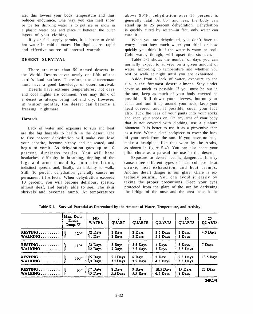
ice; this lowers your body temperature and thusreduces endurance. One way you can melt snowor ice for drinking water is to put ice or snow ina plastic water bag and place it between the outerlayers of your clothing.
If your fuel supply permits, it is better to drinkhot water in cold climates. Hot liquids area rapidand effective source of internal warmth.
DESERT SURVIVAL
There are more than 50 named deserts inthe World. Deserts cover nearly one-fifth of theearth’s land surface. Therefore, the aircrewmanmust have a good knowledge of desert survival.
Deserts have extreme temperatures; hot daysand cool nights are common. You may think ofa desert as always being hot and dry. However,in winter months, the deser t can become afreezing nightmare.
Hazards
Lack of water and exposure to sun and heatare the big hazards to health in the desert. Oneto five percent dehydration will make you loseyour appetite, become sleepy and nauseated, andbegin to vomit. As dehydration goes up to 10pe rcen t , d i zz ines s r e su l t s . You wi l l haveheadaches, difficulty in breathing, tingling of thel egs and a rms caused by poo r c i r cu l a t i on ,indistinct speech, and, finally, an inability to walk.Still, 10 percent dehydration generally causes nopermanent ill effects. When dehydration exceeds10 percent, you will become delirious, spastic,almost deaf, and barely able to see. The skinshrivels and becomes numb. At temperatures
above 90°F, dehydrat ion over 15 percent isgenerally fatal. At 85° and less, the body canstand up to 25 percent dehydration. Dehydrationis quickly cured by water—in fact, only water cancure it.
When you are dehydrated, you don’t have toworry about how much water you drink or howquickly you drink it if the water is warm or cool.Cold water, though, will upset the stomach.
Table 5-1 shows the number of days you cannormally expect to survive on a given amount ofwater, according to temperature and whether yourest or walk at night until you are exhausted.
Aside from a lack of water, exposure to thesun is the foremost desert ailment. Stay undercover as much as possible. If you must be out inthe sun, keep as much of your body covered aspossible. Roll down your sleeves, button yourcollar and turn it up around your neck, keep yourhead covered, and, if possible, cover your facealso. Tuck the legs of your pants into your socksand keep your shoes on. On any area of your bodythat is not covered with clothing, use a sunburnointment. It is better to use it as a preventive thanas a cure. Wear a cloth neckpiece to cover the backof your neck from the sun. If you have no hat,make a headpiece like that worn by the Arabs,as shown in figure 5-40. You can also adapt yourpilot chute as a parasol for use in the desert.
Exposure to desert heat is dangerous. It maycause three different types of heat collapse—heats t roke , hea t exhaus t i on , and hea t c r amps .Another desert danger is sun glare. Glare is ex-tremely painful . You can avoid i t easi ly bytaking the proper precautions. Keep your eyesprotected from the glare of the sun by darkeningthe bridge of the nose and the area beneath the
Table 5-1.—Survival Potential as Determined by the Amount of Water, Temperature, and Activity
5-32
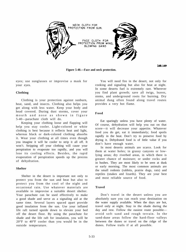
Figure 5-40.—Face and neck protection.
eyes; use sunglasses or improvise a mask foryour eyes.
Clothing
Clothing is your protection against sunburn,heat, sand, and insects. Clothing also helps youget along with less water. Keep your body andhead covered. During dust storms, cover yourm o u t h a n d n o s e a s s h o w n i n f i g u r e5-40—parachute cloth will do.
Keeping your clothing loose and flapping willhelp you stay cooler. Light-colored or whiteclothing is best because it reflects heat and light,whereas black or dark-colored clothing absorbsit. Wear your clothing at all times even thoughyou imagine it will be cooler to strip it all off. Itwon’t. Stripping off your clothing will cause yourperspiration to evaporate too rapidly, and you willlose i ts cooling effects . Besides, the rapidevaporation of perspiration speeds up the processof dehydration.
Shelter
Shelter in the desert is important not only toprotect you from the sun and heat but also toprotect you from the cool of the night andoccasional rain. Use whatever materials areavailable to improvise a suitable desert shelter.Your parachute can be used effectively to makea good shade and serve as a signaling aid at thesame time. Several layers spaced apart providegood insulation from the sun. Use your inflatedlife raft turned upside down to elevate your bedoff the desert floor. By using the parachute forshade and the life raft for insulation, you will be20°F to 40°F cooler than you would be in theoutside temperature.
You will need fire in the desert, not only forcooking and signaling but also for heat at night.In some deserts fuel is extremely rare. Whereveryou find plant growth; save all twigs, leaves,stems, and underground roots for burning. Dryanimal dung often found along travel routesprovides a very hot flame.
Food
Eat sparingly unless you have plenty of water.Of course, dehydration will help you out on thatscore—it will decrease your appetite. Whateverfood you do get, eat it immediately; food spoilsrapidly in the heat. Don’t try to preserve food bydrying it. Dehydrated food is of little value if youdon’t have enough water.
In most deserts animals are scarce. Look forthem at water holes; in grassy canyons or low-lying areas; dry riverbed areas, in which there isgreater chance of moisture; or under rocks andin bushes. They are most likely to be seen at duskor early morning. The most common animals arethe small rodents (rabbits, prairie dogs, rats) andreptiles (snakes and lizards). They are your bestand most reliable source of food.
Travel
Don’t travel in the desert unless you areabsolutely sure you can reach your destination onthe water supply available. When the days are hot,travel only at night. Stay in the shade during theday and rest. Follow the easiest route possible—a v o i d s o f t s a n d a n d r o u g h t e r r a i n . I n t h esand-dune areas follow the hard-floor valleysbetween the dunes or travel on the ridge of thedunes. Follow trails if at all possible.
5-33
Beware of flash floods when you are travelingalong dry watercourses, particularly in the vicinityof mountains. You should never make camp ina stream bed; while rain in the desert is scare,storms can and do produce flash flooding veryquickly.
TROPIC SURVIVAL
When used with reference to survival, the termtropics refers primarily to jungles, for those arethe parts of the tropics that present survivalproblems distinctly different from those in otherparts of the world.
Hazards
Most s tor ies about the animals , snakes,spiders, and nameless terrors of the jungle arepure bunk. You are probably safer from suddendeath in the jungle than in most big cities. Youwill probably never see a poisonous snake or alarge animal. What may scare you most are thehowls, screams, and crashing sounds made bynoisy monkeys, birds, and insects.
The real dangers of the tropics are the insects,many of which pass on diseases. Probably theworst disease is malaria, which is transmitted bythe mosqui to. That is why the survival ki tprovides a mosqui to headnet . Wear this netregularly, especially at dawn and dusk whenmosquitoes are the thickest; use insect repellent,wear gloves, and take Atabrine pi l ls too. Asmudge fire also helps keep mosquitoes away,especially at dawn and dusk.
There are many other insects and pests in thejungle—ticks, leeches, scorpions, centipedes, andspiders, to name just a few. Stings or bites fromthese insects can create infection and cause illness.Frequently check your body and your clothing forinsects and get rid of them. Beware of scratchesalso. In the jungle even the slightest scratch cancause serious infection within hours.
Clothing
As with the Arctic and the desert, clothing inthe tropics serves as a protection against exposure,insects, and plant life. You should keep yoursleeves rolled down and buttoned. Tuck the legsof your pants into your socks and keep your shoeson. This may help keep out unwanted insects suchas ticks, leeches, and ants. Always wear fullclothing in the tropics. By wearing your clothingloosely, your body will be cooler. Change your
clothing as often as it is practical. Remember dirtyclothes may lead to a skin infection; therefore,they should be washed daily, especially yoursocks.
Food and Water
Food and water are plentiful in the jungle. Itis a proven fact that a person can survive in thejungle and actually like it, if provided with a basicknowledge of how to use the animals and otherfood found in the jungle. When you are selectingfood in the jungle, watch the monkeys. Almosteverything a monkey eats is eatable by humans.There are fish in all jungle streams. Eat only fishthat have scales and look typically like a fish. Fishthat have slimy skin and unusually shaped bodiesare to be avoided.
Shelter
Night in the jungle comes very fast. So preparefor bed early. In the jungle you need more sleepthan usual to keep up your energy and strengthand to maintain resistance against disease.
Try to pick a campsite on a knoll or high spotin an open place well away from swamps. Youwill be bothered less by mosquitoes, the groundwill be dryer, and there will be more chances ofa breeze. Don’t build a shelter under large treesor trees with dead limbs. They may fall and wreckyour camp or cause injury. Don’t sleep or builda shelter under coconut trees.
In the wet jungle forest, you will need shelterfrom the dampness. If you stay with the plane,use it for shelter. Try to make it mosquitoproofby covering the openings with netting or parachutecloth.
In mountainous jungle, the nights are cold.Get out of the wind. Make a fire a few feet froma cliff or against a log or rock pile, and build yourshelter so that you get reflected heat. Arrange thereflector so that the fire doesn’t blow toward you.
FIRE MAKING
You may need fire for warmth, for keepingdry, for signaling, for cooking, and for purifyingwater. Do not build a big fire. Small fires requireless fuel, are easier to control, and their heat canbe concentrated. In cold weather small firesarranged in a circle are much more effective thanone large fire.
5-34
Preparing a Fireplace
Prepare the location of the fire carefully. Clearaway leaves, twigs, moss, and dry grass so thatyou do not start a grass or forest fire. If thesurrounding vegetation is dry, scrape the firelocation down to the bare dirt. If the fire mustbe built on wet ground, build a platform of logsor flat stones.
To get the most warmth and to protect the firefrom wind, build it against a rock or wall of logsthat will serve as a reflector to direct the heatinto your shelter. Cooking fires should be walledin by logs or stones, not only to concentrate theheat but a lso to provide a plat form for thecooking pot.
Kindling and Fuel
Some fuels cannot be ignited directly from amatch. You will need some easily flammablekindling to start a fire. Good natural kindlingmaterials are thin sticks of dry wood; dry bark;wood shavings; palm leaves; twigs; loose, ground-lying lichens; dead, upright grass straw; or ferns.If sticks are used for kindling, split them and cutlong thin shavings, leaving the shavings attached(shave stick). Store kindling in a shelter to keepit dry. A little JP-5 poured on the fuel before itis ignited will help it start burning. D o n o tpour petroleum fuel on a fire already started evenif it is only smoldering.
For fuel, use dry, standing, dead wood anddry, dead branches. Dead wood is easy to splitand break-pound it on a rock. The inside offallen tree trunks and large branches may be dryeven if the outside is wet; use the heart of thewood. Green wood that will burn, especially iffreely split, can be found almost everywhere. Intreeless areas, you will look for other naturalfuels, such as dry grass that can be twisted intobunches, dried animal dung, and animal fats;sometimes you can even find coal, oil shale, oroily sand lying on the surface. If no natural fuelsare available and you are with the aircraft, burnaircraft fuel and lubricating oil or a mixture ofeach. Hydraulic fluid is specifically designed andmanufactured not to burn; therefore, it shouldnot be used.
Fire Making With Matches and Lighter
Prepare a fireplace. Get all materials togetherbefore trying to start the fire. Make sure thatmatches, kindling, and fuel are dry. Have enough
fuel on hand to keep the fire burning. Arrangea small amount of kindling in a low pyramid.Arrange the kindling close enough together topermit flames to lick from one piece to another.Leave a small opening for lighting.
Save matches by using a candle (if available)to light the fire. If you have no candle, use a shavestick or make a faggot of thin, dry twigs, tiedloosely. Shield the match from the wind as youlight the candle or faggot. Apply the lightedcandle or faggot to the lower windward side ofthe kindling, shielding it from the wind.
Small pieces of wood or other fuel can beplaced gently on the kindling before lighting orcan be added after the kindling begins to burn.Lay on smaller pieces first, adding larger piecesof fuel as the fire catches. Do not smother the fireby crushing the kindling with heavy wood. Do notmake the fire too big. Do not waste fuel.
Fire Making With Special Equipment
A flare can be used to start a fire; however,it should be used only as a last resort. Someemergency kits contain small fire starters, wind-proof matches, and other aids.
Fire Making Without Matches
First, find or prepare one of the followingkinds of tinder: very dry, powdered wood; finelyshredded, dry bark; the shredded pith of a deadpalm frond; lint from unraveled cloth, cotton,twine, or rope; first-aid gauze bandage; fuzzy orwoolly material scraped from plants; fine birdfeathers or birds’ nests; field-mouse nests; or finewood dust produced by insects, often found underbark of dead trees. Tinder must be bone dry.Tinder will burn more easily if you add a fewdrops of aircraft fuel or mix it with powder takenfrom a cartridge. Once tinder is prepared, putsome in a waterproof container for future use.
Once you have the tinder, light it in a placeshel tered from the wind. Several addi t ionalmethods of starting a fire are described in thefollowing paragraphs.
Flint and Steel
Striking sparks with flint and steel is the easiestand most reliable way of starting a fire withoutmatches. Use the flint fastened to the bottom ofthe waterproof match case. If you have no flint,look for apiece of hard rock from which you canstrike sparks. If it breaks or scars when struck
5-35
with steel, throw it away and find another. Holdyour hands close over the dry tinder; strike theflint with a knife blade or other small piece of steelwith a sharp, scraping, downward motion so thatthe sparks fall in the center of the tinder. Addinga few drops of JP-5 to the tinder before you strikethe flint will make the tinder flame up-for safety,keep your head to one side. When the tinderbegins to smolder, fan it gently into a flame. Thentransfer the blazing tinder to the kindling pile oradd kindling gradually to the tinder. The wristcompass furnished in the individual survival kit(SRU-31 /P ) can be u sed t o l oca t e / i den t i fyiron-base lodestone.
Burning Glass
Any convex lens can be used in bright sunlightto concentrate the sun’s rays on the tinder andstart it burning.
Friction
There are many methods of making fire byfriction (bow and drill, fire plough, fire thong,etc.), but all require practice. If you are proficientin one of these methods, use it; but remember thatflint and steel will give the same results with lesswork .
Electric Spark
If you are with the aircraft and have a livestorage battery, direct a spark onto the tinder byscratching the ends of wires together to producean arc.
Burning Aircraft Fuel
If you are with the aircraft, you can improvisea stove to burn jet fuel, lubricating oil, or amixture of them. Place 1 to 2 inches of sand orfine gravel in the bottom of a can or othercontainer and add fuel. Be careful when lighting;the fuel may burst into flames at first. Make slotsat the top of the canto let flame and smoke out,and punch holes just above the level of the sandto provide a draft. To make a fire burn longer,mix fuel with oil. If there is no container, simplydig a hole in the ground, fill it with loose dirt,pour on fuel, and light; take care to protect yourface and hands. Always ensure that you handlefuel carefully to prevent spilling it on yourclothing.
You can use lubricat ing oi l with a wickarrangement for fuel. Make the wick of string,rope, rag, or even a cigarette, and rest it on theedge of a receptacle filled with oil. Also, soakrags, paper, wood, or other fuel in oil, and throwthem on the fire.
You can also make a stove out of any emptywaxed ration carton by cutting off one end andpunching a hole in each side near the unopenedend. Stand the carton on the closed end; stuff anempty sack loosely inside the carton, leaving anend hanging over the top; light this end—the stovewill burn from the top down and will boil morethan a pint of water.
Useful Hints
Do not waste matches by trying to start apoorly prepared fire. Do not use matches forlighting cigarettes; get alight from the fire or usea burning lens. Do not build unnecessary fires;save your fuel. Practice primitive methods ofmaking fires before all the matches are gone.
Carry some dry tinder with you in a water-proof container. Expose it to the sun on dry days.Adding a little powdered charcoal will improvei t and al low the t inder to s tay dry, as thecharcoal will absorb small quantities of watervapor from the humidity. Collect good tinderwherever it can be found.
Collect kindling along the trail before makingcamp. Keep firewood dry under shelter. Dry dampwood near the fire so that it can be used later.Save some of the best kindling and fuel for quickfire making in the morning.
To split logs, whittle hardwood wedges anddrive them into cracks in the log with a rock orclub; split wood burns more easily.
To make a fire last overnight, place large logsover it so that the fire will burn into the heart ofthe logs. When a good bed of coals has beenformed, cover it lightly with ashes and then dryearth. In the morning the f i re wil l s t i l l besmoldering.
Fire can be carried from one place to anotherin the form of a lighted punk, smoldering coconuthusk, or slow-burning coals. When you want anew fire, fan the smoldering material into flame.
Do not waste f i re-making mater ials . Useonly what is necessary to start a fire and to keepit going for the purpose needed. Put out the fireupon leaving the campsite.
ARCTIC.— Do not build a fire under a snow-covered tree-snow may fall and put out the fire.
5-36
Low, dead, needle-bearing branches of stand-ing spruce trees are good fuel. On the tundra,wood is scarce. Look for any woody bush orshrub; burn roots as well as stems. Look for drytwigs in willow thickets or for dry grasses. On thecoasts, look for driftwood.
Animal fat and bones can be used as fuel. Putchunks of fat on a stick or bone framework oron top of a perforated can with a wick of greasycloth or sphagnum moss underneath, and light thewick. Congealed oil can be burned in the sameway.
A candle burning in a tin can makes a simpleheater for the shelter.
In cold weather, drain oil from the aircraft andstore it for fuel. If the temperature is not lowenough to solidify the oil, leave it in the aircraftand drain it off when needed.
TROPICS.— In the tropics, wood is plentiful.Even if it is wet outside, the heart of dead woodwill be dry enough to burn. Dry wood can alsobe found hanging in the network of vines orlying on bushes.
In palm country, good tinder can be obtainedfrom the fibers at the bases of palm leaves. Theinsides of dry termite nests make good kindling.
Keep spare wood dry by stowing it under theshelter. Dry out wet kindling and fuel near thefire for future use.
SURVIVAL SELF-TREATMENTFIRST AID
During a survival situation the one thing thatcan jeopardize the aircrewman’s ability to surviveis a medical problem. Injuries incurred duringejection, parachute descent, and/or parachutelanding can reduce survival expectancy as well ascompromise the ability to evade the enemy.
Military personnel must be able to treat theirinjuries and sicknesses in a survival situation. Thetreatments described in this chapter are suitablefor application by nonmedical personnel.
Some of the first-aid procedures describedmay be substandard compared with presentmedical standards within U.S. medical facilities.However, in a survival situation, they will increaseyour survival expectancy.
Health and Hygiene
In a survival situation, cleanliness is more thana virtue. It is essential if infection is to beprevented. Since skin is the first line of defense
for your body, you must give particular attentionto the washing of your face, hands, armpits,groin, and feet to minimize the chance of smallscratches and abrasions becoming infected. Keep-ing the hands clean is especially important becausemost germs are introduced to the body by thehands. Keep fingernails short to prevent scratches;scratches as well as cuts and insect bites can causeserious infections, especially in the tropics. If anantiseptic is available use it on even the smallestof scratches or insect bi tes . Remember, aninfection may hurt your chances of survival.
Clean clothes help to prevent infections andchafing, especially fungal infections that arecommon in the tropics. If washing clothes is notpossible, at least shake and air clothing in thesun.
Soap is not essential to keeping clean. Asubstitute of ashes, sand, loamy soil, or otherexpedients may be used in cleaning the body andthe utensils used in cooking and eating.
Intestinal Illnesses
Contaminated water or spoiled food, fatigue,overeating in hot weather, or using dirty utensilsmay cause diarrhea and other intestinal illnesses.Cook or wash food carefully before eating. Whenpossible, purify water by boiling for 10 minutes;this will leave no doubt as to water purity at anyaltitude. If diarrhea does occur, the following fieldtreatments may be used:
l Rest and fast, except for drinking water,for the first 24 hours; then take only liquid foods,and avoid starches.
. Eat several small meals instead of one ortwo large ones. Drink tannic tea or eat clay, chalk,or charcoal. Once the diarrhea has stopped, donot worry about lack of bowel movement. Thiswill take care of itself in a few days provided youhave an ample daily supply of water.
Foot Care
If traveling afoot in a survival situation, youshould take particular care of your feet. Removeclots of material from socks to eliminate possiblesources of friction and ensure that shoes fitproperly. If possible, air your shoes and socks atnight by putting them on small stakes. This keepsthe insides dry and eliminates the danger ofinsects crawling inside. Watch for blisters andapply adhesive tape smoothly to your skin
5-37

wherever shoes rub. If you have blisters and theyburst, leave the skin in place and apply a cleandressing. Carrying an extra pair of socks in yoursurvival vest is suggested. At least once per day,clean, dry, and massage your feet to ensureadequate circulation. Remember, trench foot iscaused by prolonged exposure to wet, usuallycold, conditions; but it may be developed in thetropics. If symptoms of trench foot appear-thatis , t ingl ing, numbness, swell ing, bl is ters , orsores—pay extra attention to your feet and givethem proper care.
Control of Bleeding
The control of heavy bleeding is extremelyimportant under all conditions, but it is of evengreater importance in a survival situation sincetransfusions are not possible. When breathingceases in conjunction with heavy bleeding, youmust first take action to initiate breathing, thento stop the bleeding.
NOTE: Never apply a tourniquet unless thatis the only way to stop bleeding from an extremity.
Restoration of Breathing
When breathing signs are absent, the mostcommon cause is blockage of the airway. Ifnormal f i rs t -aid procedures fai l to clear theairway and res tore breathing, you have onealternate procedure. This procedure is called acricothyroidotomy and can be performed suc-cessfully by unskilled nonmedical personnel. Toperform a cricothyroidotomy, proceed as follows:
1. Locate the thyroid cart i lage (Adam’sapple), which is the largest bony protrusion in thecenter line of the neck.
2. Locate the cr icoid cart i lage ( the f i rs tcircular ridge below the Adam’s apple). The pointof incision is the depression immediately abovethe cricoid cartilage.
3. Using a sterile surgical razor blade, ifavailable, or any other cutting instrument in anemergency, make a lateral incision one-fourth toone-half of an inch wide and approximatelyone-fourth of an inch deep into the trachea.
4. Insert the lower half of a ball-point penbarrel or any similar rigid tube into the incisionone-half to three-fourths of an inch or untilmovement of air is felt or heard.
5. Secure the tube with tape if it is to be leftin place for an extended period of time or if thevictim is to be transported.
Control of Pain
Control of pain accompanying disease orinjury is extremely difficult because pain cannotbe measured. The severity of pain accompanyingany disease or injury is relative to the individual’sabi l i ty to withstand or cope with that pain.Although some individuals can tolerate a greatdeal of pain, others cannot. Psychological injurymay a l t e r an i nd iv idua l ’ s pa in t h r e sho ld .Regardless of this difficulty, every effort shouldbe made to control or eliminate pain, not onlybecause of its adverse effect on morale, but alsobecause it contributes to shock and makes asurvivor less capable of performing other essen-tial tasks. The ideal method for pain reductionis to eliminate its cause. Since this is not alwayspossible , the fol lowing methods are recom-mended:
. Reduce movement of the painful area.Immobilize the wounded area in a position thatp r o v i d e s m a x i m u m c o m f o r t a n d e a s e o fmaintenance. Use splints and bandages.
. Apply a clean dressing that will protect thewound from the air and from painful contactswith objects in the environment.
l Apply hot or cold compresses. Try bothhot and cold compresses to determine whichoffers the most relief.
. A common injury sustained by downedaircrew members is broken teeth. This results inextreme pain because the nerves are exposed toair. To ease the pain, take the following steps:
. Cover broken teeth with pine or othertree saps or any waxy substance.
. Drink tea made from the boiled innerbark of a willow tree. The bark contains anactive substance called salicylate, which is anaspirin substitute. Aspirin will prevent blood fromclotting. Pain-relieving drugs should be givensparingly, and then only to relieve true pain, notto soothe the victim’s apprehension. The onlyready-made pain reliever available to aircrewmembers is the aspirin located in the SRU-31/PMedical Packet #1.
Control of Shock
Shock is frequently the most serious conse-quence of an injury. You should become familiar
5-38
with the signs and symptoms of shock so that thecondition may be anticipated, recognized, anddealt with effectively. The best approach to shocktreatment is to treat all survivors suffering frommoderate and severe injuries for shock. Act!Don’t wait! Anticipate shock and take care of italong with treatment of the specific injury.
. Giving a survivor fluids by mouth in thetreatment of shock is normally not recommended.However, in survival situations, recovery mayoften depend on adequate hydration. In an earlyshock incident, giving the survivor small amountsof fluid by mouth maybe beneficial, provided heis conscious, can swallow, and has no internalinjuries. Burn victims particularly need largeamounts of water to replace their loss of fluids.
. Emotional shock frequently follows anemergency. This type of shock originates in them i n d a n d m a y o c c u r e v e n w i t h o u t i n j u r y .Resistance to and the impact of this type of shockvaries widely. It depends on your physical makeupand is related to the amount of training you havepreviously received. Comfort and reassurancecoupled with rest and relaxation after you are clearof immediate dangers is very effective in manage-ment of the survivor suffering from emotionalshock.
Symptoms of Shock
A person suffering from shock shows symp-toms that are directly or indirectly related to thepoor circulation of the blood. The pulse is weakand rapid. Breathing is likely to be shallow, rapid,and irregular, because the poor circulation of theblood affects the breathing center in the brain.The temperature near the surface of the body isl o w e r e d b e c a u s e o f t h e p o o r b l o o d f l o w ;therefore, the face, arms, and legs feel cold to thetouch. Sweating is likely to be very noticeable. Aperson in shock is usually very pale, but in somecases there may be a bluish or reddish color tothe skin. The pupils of the eyes are usually dilated(enlarged).
If the victim is conscious, he may complainof thirst. He may have a feeling of weakness,faintness, or dizziness. He may feel nauseous.Also, the person may be very restless and feelfrightened and anxious. As shock deepens, thesesigns gradually disappear and the victim becomesless and less responsive to what is going on aroundhim. Even pain may not arouse him. Finally, thevictim may become unconscious.
It is unlikely that you will see all thesesymptoms of shock in any one case. Some of themappear only in the late stages of shock when thedisturbance of the blood flow has become so greatthat the vict im’s l i fe is in ser ious danger .Sometimes the signs of shock maybe disguisedby other signs of injury. It is important to knowwhat symptoms indicate the presence of shock,but do not ever wait for symptoms to developb e f o r e b e g i n n i n g t h e t r e a t m e n t f o r s h o c k .Remember, EVERY SERIOUSLY INJUREDPERSON IS LIKELY TO DEVELOP SERIOUSS H O C K .
Treatment of Shock
In many emergency s i tuat ions, the mosthelpful thing you can do for an injured personis to begin treatment for shock. If shock has notyet developed, the treatment may actually preventits occurrence; if it has developed, you may beable to keep it from reaching a critical point. Aswe have seen, shock creates a vicious cycle—thatis, the worse it is, the worse it becomes. It isextremely important that you begin treatment atthe earliest opportunity.
It is important to keep the victim as calm aspossible because excitement and fright will affecthis condition and may even bring on shock. Tryto prevent the victim from seeing his injuries, andreassure him that he will be properly cared for.Keep all unnecessary persons away, as theirconversation regarding the victim’s injuries mayincrease his agitation.
A p e r s o n i n s h o c k i s o f t e n t h i r s t y . N oparticular harm will be done if you allow thevictim to moisten his mouth and lips with coolwater, if it will make him more comfortable. Butin general, there is no need to give him anythingto drink unless you are in a position where medicalassistance will not be available for an excessivelylong period of time.
If medical care will not be available, youshould give the victim SMALL AMOUNTS ofwarm water, preferably mixed with 1 teaspoon ofsalt and 1/2 teaspoon of baking soda per quartor liter. This should be done if he is conscious,able to swallow, and has not suffered internalinjuries.
In the case of burns, an exception must bemade t o t he ru l e o f no t g iv ing l i qu id s . Aseriously burned person has an overwhelmingneed for fluids. It is, therefore, a permissible andeven desirable part of first-aid treatment for burnsto give water or other liquids. Sweet tea, fruit
5-39
juices, or sugar water maybe given if the casualtyis conscious and able to swallow, if he has nointernal injuries, and if vomiting is no problem.
One final precaution must be given concern-ing the use of liquids: NEVER GIVE ALCOHOLTO A PERSON IN SHOCK OR WHO MAYGO INTO SHOCK. Alcohol increases the bloodsupply to surface vessels and so diminishes theblood supply to the brain and other vital organs.
Heat is important in the treatment of shockto the extent that the injured person’s body heatmust be conserved. Exposure to cold, withresulting loss of body heat, can cause shock todevelop or to become worse. You will have tojudge the amount of covering to use by consider-ing the weather and the general circumstances ofthe accident. Often alight covering will be enoughto keep the casualty comfortable. Wet clothingshould be removed and dry covering provided,even on a hot day. Use blankets or any drymaterial to conserve body heat. Artificial meansof warming (for example, hot-water bot t les ,heated bricks, or heated sand) should not beordinarily used. Artificial heat may cause the lossof body fluids (by sweating), and it brings theblood closer to the surface, thus defeating thebody’s own efforts to supply blood to the vitalorgans and to the brain. Also, the warming agentmay bu rn t he v i c t im . KEEP AN INJUREDPERSON WARM ENOUGH FOR COMFORT,BUT DO NOT OVERHEAT HIM.
The best position to use for the prevention ortreatment of shock is one that encourages the flowof blood to the brain. If it is possible to place theinjured person on his back on a bed, cot, orstretcher, you can raise the lower end of thesupport about 12 inches so that his feet will behigher than his head. If the circumstances of theaccident make it impossible to do this, it mightstill be possible for you to raise his feet and legsenough to help the blood flow to the brain.Sometimes it is possible to take advantage of anatural slope of ground and place the casualty sothat his head is lower than his feet.
In every case, of course, you will have toconsider what type of injury is present before youcan decide on the best position. For example, aperson with a chest wound may have so muchtrouble breathing that you will have to raise hishead slightly. If the face is flushed rather thanpale, or if you have any reason to suspect headinjury, do not raise the feet. Rather, you shouldkeep the head level with or slightly higher thanthe feet. If the person has broken bones, you willhave to judge what position would be best both
5-40
for the fractures and for shock. A fractured spinemust be immobilized before the victim is movedat all, if further injuries are to be avoided. If youhave any doubts about the correct position to use,have the victim lie flat on his back. THE BASICPOSITION FOR TREATING SHOCK IS ONEIN WHICH THE HEAD IS LOWER THANTHE FEET. Do the best you can, under thepart icular circumstances, to get the injuredperson into this position. In any case, never leta seriously injured person sit, stand, or walkaround.
Distinguishing Characteristicsof Poisonous Snakes
The first step to treating a snakebite is todetermine whether the snake is poisonous. Manyh a r m l e s s s n a k e s b i t e i n s e l f - d e f e n s e .Distinguishing characteristics that help to deter-mine if the snake is poisonous follow:
VIPERS.— The viper has two long, foldingfangs at the front of the upper jaw. A pit viperalso has a small, deep pit between the eyes andthe nostrils, slit-like pupils of the eyes, and a flat,triangular head; the scales behind the anus are inone piece. Rattlesnakes, copperheads, and moc-casins are pit vipers; all vipers are poisonous.
CORALS.— The coral snake has a black noseand brightly colored bands of either red, black,and yellow or red, black, and white. On coralsnakes the black and red are separated by yellowor white; on the nonpoisonous (false coral) snake,the yellow and red are separated by black. It hasshort, grooved fangs and must chew into itsvictim before the poison can be injected. The coralsnake is related to the cobra and the krait.
COBRAS.— The combat attitude of the cobrais with the forepart of the body raised verticallyand the head tilted sharply forward. Usually theneck is flattened to form a hood. These snakesare very poisonous and should be avoided.Adders are related to the cobra and can be foundthroughout the continental United States.
TREATMENT OF SNAKEBITES.— Promptac t i on t o r educe t he e f f ec t s o f po i sonoussnakebites is essential. The following is a step-by-step treatment for snakebites:
1. Avoid undue exertion. If circumstancesallow it, lie down and remain quiet. A snug
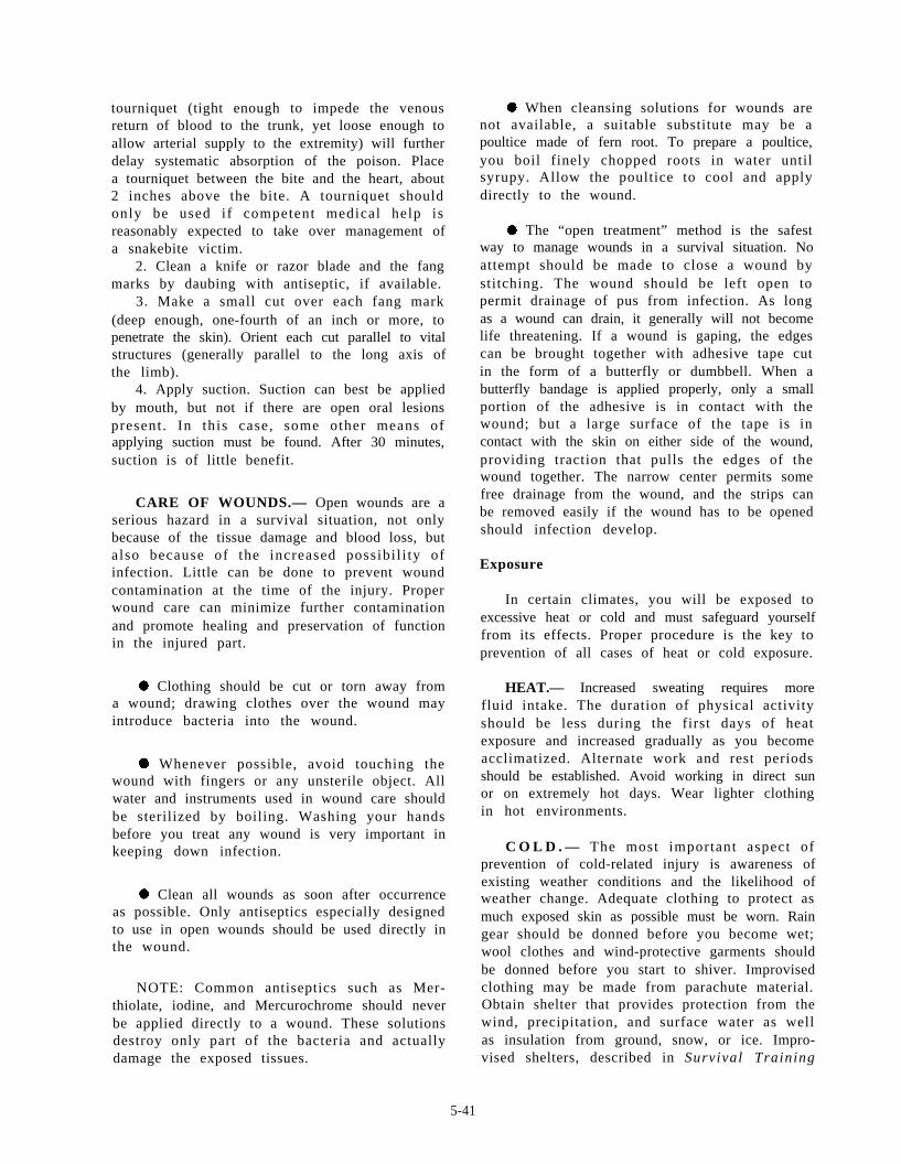
tourniquet (tight enough to impede the venousreturn of blood to the trunk, yet loose enough toallow arterial supply to the extremity) will furtherdelay systematic absorption of the poison. Placea tourniquet between the bite and the heart, about2 inches above the bite. A tourniquet shouldonly be used if competent medical help isreasonably expected to take over management ofa snakebite victim.
2. Clean a knife or razor blade and the fangmarks by daubing with antiseptic, if available.
3. Make a small cut over each fang mark(deep enough, one-fourth of an inch or more, topenetrate the skin). Orient each cut parallel to vitalstructures (generally parallel to the long axis ofthe limb).
4. Apply suction. Suction can best be appliedby mouth, but not if there are open oral lesionspresent . In this case, some other means ofapplying suction must be found. After 30 minutes,suction is of little benefit.
CARE OF WOUNDS.— Open wounds are aserious hazard in a survival situation, not onlybecause of the tissue damage and blood loss, butalso because of the increased possibi l i ty ofinfection. Little can be done to prevent woundcontamination at the time of the injury. Properwound care can minimize further contaminationand promote healing and preservation of functionin the injured part.
. Clothing should be cut or torn away froma wound; drawing clothes over the wound mayintroduce bacteria into the wound.
l Whenever possible, avoid touching thewound with fingers or any unsterile object. Allwater and instruments used in wound care shouldbe sterilized by boiling. Washing your handsbefore you treat any wound is very important inkeeping down infection.
. Clean all wounds as soon after occurrenceas possible. Only antiseptics especially designedto use in open wounds should be used directly inthe wound.
NOTE: Common antiseptics such as Mer-thiolate, iodine, and Mercurochrome should neverbe applied directly to a wound. These solutionsdestroy only part of the bacteria and actuallydamage the exposed tissues.
. When cleansing solutions for wounds arenot available, a suitable substitute may be apoultice made of fern root. To prepare a poultice,you boil finely chopped roots in water untilsyrupy. Allow the poultice to cool and applydirectly to the wound.
. The “open treatment” method is the safestway to manage wounds in a survival situation. Noattempt should be made to close a wound bystitching. The wound should be left open topermit drainage of pus from infection. As longas a wound can drain, it generally will not becomelife threatening. If a wound is gaping, the edgescan be brought together with adhesive tape cutin the form of a butterfly or dumbbell. When abutterfly bandage is applied properly, only a smallportion of the adhesive is in contact with thewound; but a large surface of the tape is incontact with the skin on either side of the wound,providing traction that pulls the edges of thewound together. The narrow center permits somefree drainage from the wound, and the strips canbe removed easily if the wound has to be openedshould infection develop.
Exposure
In certain climates, you will be exposed toexcessive heat or cold and must safeguard yourselffrom its effects. Proper procedure is the key toprevention of all cases of heat or cold exposure.
HEAT.— Increased sweating requires morefluid intake. The duration of physical activityshould be less during the first days of heatexposure and increased gradually as you becomeacclimatized. Alternate work and rest periodsshould be established. Avoid working in direct sunor on extremely hot days. Wear lighter clothingin hot environments.
C O L D . — The most important aspect ofprevention of cold-related injury is awareness ofexisting weather conditions and the likelihood ofweather change. Adequate clothing to protect asmuch exposed skin as possible must be worn. Raingear should be donned before you become wet;wool clothes and wind-protective garments shouldbe donned before you start to shiver. Improvisedclothing may be made from parachute material.Obtain shelter that provides protection from thewind, precipitation, and surface water as wellas insulation from ground, snow, or ice. Impro-vised shelters, described in Survival Training
5-41
Manual, NAVAIR 00-80T-101, will be useful incombating exposure.
SNOW BLINDNESS.— Exposure to reflectedsunlight from snow, ice, or water, even on greyovercast days, can result in sunburn of the tissuescomprising the surface of the eye, as well as theretina, producing snow blindness.
Symptoms.— Symptoms may not be apparentuntil up to 12 hours after exposure. The eyesinitially feel irritated and dry; then, as time passes,eyes feel as though they are ful l of sand.Blinking and moving the eyes may be extremelypainful. The eyelids are usually red, swollen, anddifficult to open.
Remedial Action.— A mild case will heal spon-taneously in a few days, but you can obtain somer e l i e f b y a p p l y i n g c o l d c o m p r e s s e s a n d alightproof bandage. An ophthalmic ointment canbe applied hourly to relieve pain and lessen theinflammatory reaction.
W A R N I N G
Do not rub your eyes.
Prevent ion . — S n o w b l i n d n e s s c a n b eprevented by constant use of sunglasses or a tintedhelmet visor. If the glasses or helmet are lost, anemergency set of goggles can be made from a thinpiece of leather, cardboard, or other lightproofmaterial. Cut the material the width of the facewith horizontal slits over the eyes. These impro-vised goggles can be held in place with string orcord from the parachute shroud lines attached tothe sides and tied at the back of the head.
As a first class or chief petty officer, you mustassume more responsibility for yourself and thosearound you. You will be the resident expert inmatters of survival equipment . You wil l beexpected to teach your subordinate maintenancepersonnel and your unit’s aircrewmen as well.This means that you must continue to educateyourself by studying everything available relatedto survival equipment. You are a key factor inthe survival of those entrusted to your care.
5-42

INDEX
A
Aircrew survival equipment training, 5-1 to5-42
sea survival, 5-1 to 5-29flotation, 5-2 to 5-20
life preservers, 5-3 to 5-12life rafts, 5-12 to 5-20
rescue devices and procedures, 5-20to 5-23
rescue hook, 5-21rescue strop (unassisted rescue),
5-22 to 5-23rescue swimmer’s harness (swim-
mer-assisted rescue), 5-21 to5-22
rescue strop (horse collar) (swim-mer-assisted rescue), 5-23 to 5-27
forest penetrator, 5-23 to 5-24forest penetrator with flotationcollar (swimmer-assisted res-
cue), 5-24rescue net, 5-25 to 5-26rescue net (swimmer-assisted,
single rescue), 5-26 to 5-27rescue seat, 5-24 to 5-25rescue seat (swimmer-assisted
rescue), 5-25search and rescue (SAR) communi-
cation, 5-27 to 5-29handsignals, 5-29radios, 5-27 to 5-29
survival, 5-30 to 5-42arctic survival, 5-30 to 5-32
shelter, 5-30 to 5-31signaling, 5-31water problems, 5-31 to 5-32
desert survival, 5-32 to 5-34clothing, 5-33food, 5-33hazards, 5-32shelter, 5-33travel, 5-33 to 5-34
Aircrew survival equipment training-Continuedsurvival—Continued
fire making, 5-34 to 5-37burning aircraft fuel, 5-36burning glass, 5-36electric spark, 5-36fire making with matches and
lighter, 5-35fire making with special equip-
ment, 5-35fire making without matches,
5-35flint and steel, 5-35 to 5-36friction, 5-36kindling and fuel, 5-35preparing a fireplace, 5-35useful hints, 5-36 to 5-37
land survival, 5-30survival self-treatment first aid,
5-37 to 5-42control of bleeding, 5-38control of pain, 5-38control of shock, 5-38 to 5-39distinguishing characteristics of
poisonous snakes, 5-40 to 5-41exposure, 5-41 to 5-42foot care, 5-37, to 5-38health and hygiene, 5-37intestinal illnesses, 5-37restoration of breathing, 5-38symptoms of shock, 5-39treatment of shock, 5-39 to 5-40
tropic survival, 5-34
clothing, 5-34
food and water, 5-34
hazards, 5-34
shelter, 5-34
Altitude sensing system, 2-11
Arctic survival, 5-30 to 5-32
I-1

C
Carbon dioxide transfer equipment, 3-1 to3-13
model SC-5, 3-1 to 3-5installing and servicing new equip-
ment, 3-2 to 3-4maintenance, 3-4 to 3-5
Walter Kidde transfer unit, 3-5 to 3-13C O2 cylinders and safety disc, 3-11components, 3-5 to 3-8
compressor assembly, model 4211carbon dioxide transfer unit,3-6
compressor assembly, model4211-1 carbon dioxide transferunit, 3-7
motor, 3-6multibreaker, 3-6running gear assembly, 3-7 to 3-8
maintenance, 3-8 to 3-11cleaning, 3-10 to 3-11plunger packing, 3-9 to 3-10safety disc, 3-10troubleshooting, 3-9
replacing safety discs and washerson inflation valves, 3-13
service and operational instructions,3-8
winterizing carbon dioxide cylinders,3-11 to 3-13
Chamber bleed system, 2-11 to 2-12Cleaning and oiling, sewing machine, 4-2 to
4-3Cleaning, test stand 59A120, 1-4 to 1-5C O2 cylinders and safety disc, 3-11Components, Walter Kidde transfer unit,
3-5 to 3-8Compressor assembly, model 4211 carbon
dioxide transfer unit, 3-6Compressor assembly, model 4211-1 carbon
dioxide transfer unit, 3-7Control of bleeding, 5-38Correction card preparation
1-5Correction cards, 1-5 to 1-8
and calibration,
D
Desert survival, 5-32 to 5-34Devices and procedures, rescue, 5-20 to 5-23Differential pressure gage (DF-1), 1-6
Differential system, 2-8 to 2-9Disassembly and reassembly of the 111 W 155
sewing machine, 4-21 to 4-37disassembly, 4-21 to 4-27reassembly, 4-27 to 4-31
E
Exposure, 5-41 to 5-42
F
Fire making, 5-34 to 5-37Flotation, 5-2 to 5-20Flow measuring system, 2-12 to 2-13Foot care, 5-37 to 5-38Forest penetrator, 5-23 to 5-24
with flotation collar, 5-24
H
Hand signals, 5-29Health and hygiene, 5-37Hook, rescue, 5-21Horse collar (rescue strop), 5-23 to 5-27
I
Installing and servicing new equipment, modelSC-5, 3-1 to 3-5
Intestinal illnesses, 5-37
L
Land survival, 5-30Life preservers, 5-3 to 5-12Life rafts, 5-12 to 5 - 2 0Linear flow elements (FLM-4), (FLM-3),
(FLM-2), and (FLM-1), 1-7 to 1-8Liquid oxygen converter test stand 59A120,
1-1 to 1-1159A120 test stand, the, 1-1 to 1-11
cleaning, 1-4 to 1-5correction card preparation and cali-
bration, 1-5correction cards, 1-5 to 1-8
differential pressure gage (DF-1),1-6
linear flow elements (FLM-4),(FLM-3), (FLM-2), and(FLM-1), 1-7 to 1-8
I-2

Liquid oxygen converter test stand59A120—Continued
59A120 test stand, the—Continuedcorrect ion cards-Continued
low pressure test gage (PG-4),1-7
test pressure gage (PG-1), 1-6 to1-7
periodic inspections, 1-1 to 1-4preparation for use, 1-1repairing and replacing parts, 1-11
heat exchange panel, 1-11lubrication, 1-11
troubleshooting, 1-8 to 1-11bell jar leakage, 1-11differential pressure gage (DF-1)
indicates low, 1-11leakage test, accessories section,
1-10leakage test, test stand, 1-10PG-1 pointer pegs, 1-10PG-1 reads low, 1-8 to 1-10PG-4 indicates low readings
consistently, 1-11Low pressure test gage (PG-4), 1-7
M
Maintenance, SC-5, 3-4 to 3-5Maintenance, Walter Kidde transfer unit,
3-8 to 3-11Model SC-5, 3-1 to 3-5
N
Net, rescue, 5-25 to 5-26Net, rescue (swimmer assisted, single rescue),
5-26 to 5-27
O
111 W 155 sewing machine, 4-1 to 4-11Oxygen component test stand (1172AS100),
2-1 to 2-16periodic inspections, 2-2 to 2-16
altitude sensing system, 2-11chamber bleed system, 2-11 to 2-12differential pressure indicating system,
2-8 to 2-9flow measuring system, 2-12 to 2-13
input, 2-13output, 2-12
Oxygen component test stand(117AS100)—Continued
pressurizing the altitude sensingsystem, 2-11
pressurizing the chamber bleedsystem, 2-12
pressurizing the differential pressureindicating system, 2-9
pressurizing the flow measuringsystem, 2-13 to 2-16
pressurizing the regulated high-pressure system, 2-5 to 2-6
pressurizing the regulated low-pressure nitrogen system, 2-6 to2-7
pressurizing the rotameter systems,2-7 to 2-8
pressurizing the supply nitrogensystem, 2-4
regulated high-pressure system, 2-4 to2-5
regulated low-pressure nitrogensystem, 2-6
rotameter system, 2-7safety precautions, 2-2supply nitrogen system, 2-2 to 2-4troubleshooting the 1172AS100 test
stand for leaks, 2-2using the vacuum system, 2-9 to 2-11vacuum system, 2-9vent flow system, 2-13
P
Pain, control of, 5-38Periodic inspections, oxygen component test
stand (117AS100), 2-2 to 2-16Periodic inspections, test stand 59A120,
1-1 to 1-4Plunger packing, 3-9 to 3-10Poisonous snakes, 5-40 to 5-41Preparation for use, test stand 59A120,
1-1Preservers life, 5-2 to 5-12Pressurizing the altitude sensing system, 2-11Pressurizing the chamber bleed system, 2-12Pressurizing the differential pressure indicating
system, 2-9Pressurizing the flow measuring system, 2-13
to 2-16Pressurizing the regulated high-pressure system,
2-5 to 2-6Pressurizing the regulated low-pressure
nitrogen system, 2-6 to 2-7
I-3

Pressurizing the rotameter systems, 2-7 to 2-8Pressurizing the supply nitrogen system, 2-4Preventive maintenance, sewing machines, 4-17
R
Radios, 5-27 to 5-29Rafts, life, 5-12 to 5-20Regulated big-pressure system, 2-4 to 2-5Regulated low-pressure nitrogen system, 2-6Repairing and replacing parts, test stand
59A120, 1-11Replacing safety discs and washers on inflation
valves, 3-13Rescue devices and procedures, 5-20 to 5-23Rescue hook, 5-21Rescue strop (unassisted rescue), 5-22 to 5-23Rescue swimmer’s harness (swimmer-assisted
rescue), 5-21 to 5-22Restoration of breathing, 5-38Rotameter system, 2-7Running gear assembly, 3-7 to 3-8
S
Safety disc, 3-10SAR communication, 5-27 to 5-29Sea survival, 5-1 to 5-29Seat, rescue, 5-24 to 5-25Service and operational instructions, 3-8Sewing machine repair, 4-1 to 4-37
disassembly and reassembly of the111 W 155 sewing machine, 4-21 to4-37
disassembly, 4-21 to 4-27alternating presser foot, 4-22arm cap, 4-21arm shaft, 4-24 to 4-25arm shaft connection belt, 4-24arm shaft connection belt pulley
position screw, 4-24balance wheel, 4-24balance wheel adjusting screw,
4-24bobbin-case opener, 4-27faceplate, 4-21feed bar, 4-26feed dog, 4-26feed indicator disc, 4-24feed-driving connection, 4-26feed-driving crank, 4-26feed-driving eccentric, 4-26feed-driving rockshaft crank, 4-25
Sewing machine repair-Continueddisassembly and reassembly of the
111 W 155 sewing machine—Continueddisassembly—Continued
feed-driving rockshaft, 4-25feed-driving rockshaft stop
collars, 4-25feed-lifting cam fork, 4-25feed-lifting eccentric, 4-26hook saddle assembly, 4-27hook saddle screw, 4-27hook-driving gear, 4-26hook-driving shaft, 4-27hook-driving shaft and attached
parts, 4-26hook-driving shaft lock ratchet,
4-26knee lifter lifting lever, 4-21knee lifter lifting lever hinge
screw, 4-21needlebar crank, 4-24needlebar crank friction washer,
4-24needlebar connecting link, 4-23needlebar connecting link oil
guard, 4-23needlebar connecting link stud,
4-24needlebar rock frame assembly,
4-23needlebar rock frame hinge stud,
4-23needlebar rock frame position
bracket, 4-23needlebar rock frame rockshaft,
4-25needlebar rock frame rockshaft
crank and connection, 4-25presser bar lifting bracket, 4-22
to 4-23presser bar lifting releasing lever
bracket guide screw, 4-22presser bar position guide, 4-22presser bar position guide lever,
4-22presser bar spring, 4-22presser bar spring bracket, 4-22presser bar spring support screw,
4-22presser-lifting bell crank, 4-22presser-lifting eccentric, the, 4-24safety clutch pulley, 4-26take-up lever hinge stud, 4-23tension release rod, 4-23thread take-up lever, 4-23
I-4

Sewing machine repair—Continueddisassembly and reassembly of the
111 W 155 sewing machine—Continueddisassembly—Continued
thread take-up lever, drivingstud, 4-23
throat plate, 4-25vibrating pressure foot, 4-23
reassembly, 4-27 to 4-31alternating presser driving rock-
shaft, 4-29arm cap, 4-31arm shaft, 4-28arm shaft connection belt pulley
position screw, 4-29arm shaft pulley and arm shaft
connection belt, 4-29balance wheel, 4-29balance wheel adjusting screw,
4-29bell crank, 4-30bobbin-case opener, 4-27faceplate, 4-31feed indicator disc, 4-29feed-driving connection and
feed-driving crank, 4-27feed-driving eccentric, 4-28feed-driving rockshaft, 4-28feed-lifting eccentric, 4-28front presser bar connecting link,
4-30hook saddle assembly, 4-27hook saddle screw, 4-27hook-driving gear, 4-28hook-driving shaft, 4-27hook-driving shaft lock ratchet,
4-27knee lifter lifting lever, 4-31knee lifter lifting lever hinge
screw, 4-31needlebar connecting link, 4-29needlebar rock frame assembly,
4-30needlebar rock frame rockshaft,
4-28presser bar, 4-30presser bar position guide, 4-30presser bar spring, 4-30presser-lifting eccentric, 4-29presser-lifting eccentric con-
nection link, 4-28safety clutch pulley, 4-28take-up lever, 4-29take-up lever driving stud,
4-29
Sewing machine repair—Continueddisassembly and reassembly of the
111 W 155 sewing machine—Continuedreassembly—Continued
thread take-up lever hinge stud,4-30
thread tension release lever rod,4-30
Shelter, 5-30 to 5-31Shock, 5-38 to 5-40
control of, 5-38 to 5-39symptoms, 5-39treatment, 5-39 to 5-40
Signaling, 5-31Singer sewing machines 31-15, 331K1, and
CONSEW C-30, 4-11 to 4-21Supply nitrogen system, 2-2 to 2-4Survival, 5-30 to 5-42Survival self-treatment first aid, 5-37 to 5-42Swimmer-assisted rescue, 5-21 to 5-22
111 W 155 sewing machine, 4-1 to 4-11adjustments, 4-8 to 4-11cleaning and oiling, 4-2 to 4-3preventive maintenance, 4-2timing the 111 W 155 machine, 4-3
to 4-8troubleshooting, 4-11
rescue net (single rescue), 5-26 to 5-27rescue seat, 5-25rescue strop (horse collar), 5-23 to 5-27rescue swimmer’s harness, 5-21 to 5-22Singer sewing machines 31-15, 331K1,
and CONSEW C-30, 4-11 to 4-21preventive maintenance, 4-17timing and adjustments, 4-17 to 4-21
adjusting the feed dog height,4-19
centering the feeding action,4-20
setting side play of feed dogs,4-20
setting the presser bar, 4-20to 4-21
timing the feed-driving eccentric,4-20
timing the needle with theshuttle, 4-18 to 4-19
T
Test pressure gage (PG-1), 1-6 to 1-7Test stand, the 59A120, 1-1 to 1-11Timing and adjustments, sewing machines,
4-17 to 4-21
I-5

Timing the 111 W 155 machine, 4-3 to 4-8Tropic survival, 5-34Troubleshooting, test stand 59A120, 1-8 to
1-11Troubleshooting the 117AS100 test stand for
leaks, 2-2 -
U
Unassisted rescue (rescue strop), 5-22 to 5-23Using the vacuum system, 2-9 to 2-11
V
Vacuum system, 2-9Vent flow system, 2-13
W
I-6
Walter Kidde transfer unit, 3-5 to 3-13Water problems, 5-31 to 5-32Winterizing carbon dioxide cylinders, 3-11
to 3-13

Assignment Questions
Information: The text pages that you are to study areprovided at the beginning of the assignment questions.

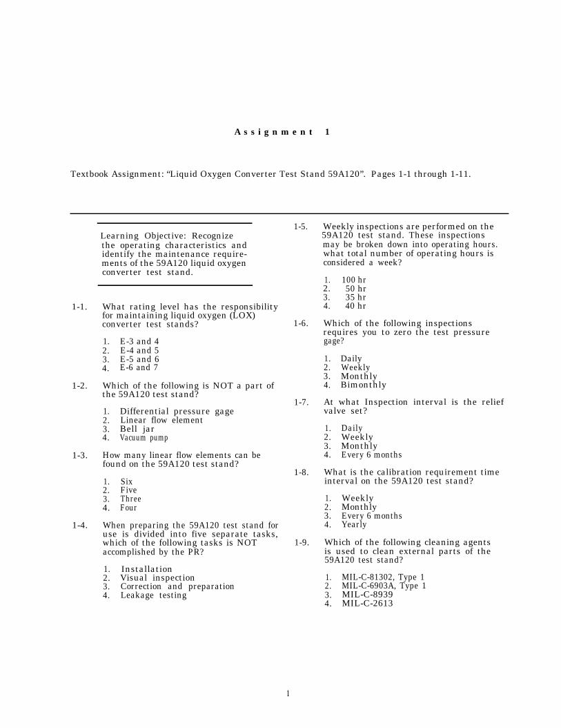
A s s i g n m e n t 1
Textbook Assignment: “Liquid Oxygen Converter Test Stand 59A120”. Pages 1-1 through 1-11.
1-1.
1-2.
1-3.
1-4.
Learning Objective: Recognizethe operating characteristics andidentify the maintenance require-ments of the 59A120 liquid oxygenconverter test stand.
What rating level has the responsibilityfor maintaining liquid oxygen (LOX)converter test stands?
1. E-3 and 42. E-4 and 53. E-5 and 64. E-6 and 7
Which of the following is NOT a part ofthe 59A120 test stand?
1. Differential pressure gage2. Linear flow element3. Bell jar4. Vacuum pump
How many linear flow elements can befound on the 59A120 test stand?
1. Six2. Five3. Three4. Four
When preparing the 59A120 test stand foruse is divided into five separate tasks,which of the following tasks is NOTaccomplished by the PR?
1. Installation2. Visual inspection3. Correction and preparation4. Leakage testing
1-5.
1-6.
1-7.
1-8.
1-9.
Weekly inspections are performed on the59A120 test stand. These inspectionsmay be broken down into operating hours.what total number of operating hours isconsidered a week?
1. 100 hr2. 50 hr3. 35 hr4. 40 hr
Which of the following inspectionsrequires you to zero the test pressuregage?
1. Daily2. Weekly3. Monthly4. Bimonthly
At what Inspection interval is the reliefvalve set?
1. Daily2. Weekly3. Monthly4. Every 6 months
What is the calibration requirement timeinterval on the 59A120 test stand?
1. Weekly2. Monthly3. Every 6 months4. Yearly
Which of the following cleaning agentsis used to clean external parts of the59A120 test stand?
1. MIL-C-81302, Type 12. MIL-C-6903A, Type 13. MIL-C-89394. MIL-C-2613
1

1-10. Where are the test adapters stored forthe 59A120 test stand?
1. In the storage compartment underthe stand
2. In the accessory tray3. Hung on the side of the test stand4. Inside the accessory toolbox
1-11. To remove dust and any foreign matterfrom the surfaces of the gage testerafter removing the front panel on the59A120 test stand, what maximum airpressure should you use?
1. 10 psig2. 15 psig3. 25 psig4. 50 psig
1-12. When you are using air pressure forcleaning, all interconnecting pipes,hoses, and fittings must be cleanedwith what maximum air pressure?
1. 50 psi2. 160 psi3. 400 psi4. 500 psi
1-13. Which of the following chemicals is usedto clean the terminals, of the LiquidOxygen Quantity Gage Tester, on the59A120 test stand?
1. Type I Freon2. Type II Freon3. Type I dry cleaning solvent4. Type II dry cleaning solvent
1-14. Who is responsible for calibrating the59A120 test stand?
1. PRs, E-6 or above2. Personnel assigned to depot level
maintenance3. On-site meteorology calibration team
1-15. What should you use to clean the O-ringthat is installed in the bell jar?
1. Distilled water2. Denatured alcohol3. Natured alcohol4. Mild soap and water
1-16. After you clean the O-ring on the belljar, it should be lubricated with whichof the following?
1. MIL G 24892. MIL G 276173. MIL G 69034. MIL G 2873
1-17. With of the following manuals givesinformation on the procedures forcorrection card preparation andcalibration?
1. NAVAIR 13-1-6.42. NAVAIR 13-1-6.53. NAVAIR 17-15BC-24. NAVAIR 17-17CAL-2
1-18. Which of the following components doesNOT require a correction card?
1. PG-12. PG-23. FLM-14. FLM-2
1-19. To prepare the correction cards, you mustconvert the actual liter-per-minute to
1. indicated millimeters2. psig3. inches of water4. inches of mercury
1-20. After converting the actual liter-per-minute, at what time will you enter theindicated flows?
1. When performing the leakage test2. When performing the daily test3. When calibrating the test stand4. Simultaneously
1-21. How many graphs are supplied with thecalibration kit for the 59A120 teststand?
1. One2. Two3. Three4. Four
1-22. How can you be sure that you have theright graphs for the test stand you aregoing to calibrate?
1. The graphs will have the same serialnumbers as the test stand
2. The graphs are color coded3. All graphs are the same
2

1-23. When preparing the differential pressuregage correction card, you must connectthe precision 0 to 100 in. H20low-pressure gage to which of thefollowing components?
1. Pressure gage calibration kit2. Relief valve3. Flowmeter 125-250 mm4. Bell jar bottom coupling
1-24. When you are preparing the differentialpressure gage correction card, whatinitial pressure is used to compare thereadings on the 0 to 100 in. H20low-pressure gage and the differentialpressure gage?
1. 25 in. H202. 50 in. H203. 100 in. H20
1-25. To complete the differential pressureqage correction card after making thecorrection for 100 in. H20, you must dropthe pressure in what increments?
1. 10 in. H202. 20 in. H203. 25 in. H20
1-26. To prepare the test pressure gagecorrection card, you must connect thebell jar bottom coupling to which ofthe following precision gages?
1. 0 to 100 psig2. 0 to 200 psig3. 0 to 500 psig4. Differential pressure gage
1-27. The pointer of the low-pressure test gagecan be adjusted by which of the followingmethods?
1. Turning the adjustment screw on theback of the gage
2. Turning the adjustment screw on thefront of the gage
3. Opening the oxygen supply valve4. Closing the oxygen supply valve
1-28. When preparing the correction card forthe low-pressure test gage, you must usethe bleed valve to reduce the pressureindicated on the precision-O-to-200-psigpressure test gage. What maximumincrements are used to reduce theindicated pressure?
1. 2 psig2. 5 psig3. 25 psig4. 50 psig
1-29. When preparing the correction card forthe low-pressure gage, you make yourfirst correction reading at 14 psig.How many other readings are required?
1. Five2. Two3. Six4. Four
1-30. When preparing the linear flow elementcorrection cards, you should start withwhich of the following 1pm flow elements?
1. 0 to 502. 0 to 1003. 0 to 1504. 0 to 200
1-31. By setting the oxygen supply valve V-6 to150 1pm on the 500- to 750-mm calibrationkit flow element, the flow, in. H20, willbe displayed on which of the followingflowmeter indicators?
1. PG-12. PG-23. PG-34. PG-4
1-32. Upon completion of any maintenance actionon the 59A120 test stand, you mustcomplete which of the following forms?
1. Ground Support Equipment Subcustodyand Periodic Maintenance Record(OPNAV 4790/50)
2. Ground Support Equipment Custody andMaintenance Record (OPNAV 4790/51)
3. both 1 and 2 above4. VIDS/MAF
1-33. Which of the following manuals containsinformation on the 59A120 test stand?
1. NAVAIR 17-15BC-202. NAVAIR 17-18BC-303. NAVAIR 13-5-5014. OPNAV 4790.2A
1-34. WhO has the responsibility to repair adefective flow element that consistentlyreads low?
1. Only personnel of the PR rate2. Only E-6 and above personnel of the
PR rate3. Local AIMD personnel assisted by the
calibration team
3

1-35. Which, if any, of the following gages, 1-42.reads pressure applied to the item undertest on the 59A120 test stand?
1. DF-1, 0 to 100 H202. PG-1, 0 to 160 psig3. PG-4, 0 to 15 psig4. None of the above
1-36. When you are testing the accessories 1-43.section for leakage, a leak will beindicated on which of the followinggages?
1. PG-12. PG-23. PG-3
1-37. When you test the accessories section 1-44.on the 59A120 test stand, what is theallowable leakage?
1. 2 psig in 10 min2. 5 psig in 10 min3. 2 psig in 15 min4. 5 psig in 15 min
1-38. The relief valve V-11 shall relieve atno more than how many psig?
1. 502. 90 1-45.3. 1104. 120
1-39. The relief valve V-11 shall be leak tightat what minimum psig?
1. 502. 903. 100 1-46.4. 110
1-40. In order to bleed the accessory sectionof the 59A120, which of the followingvalves is used?
1. V-112. V-6 1-47.3. V-54. V-1
1-41. Any time the 0 to 160 psig pressure gagepegs, it is caused by which of thefollowing parts?
With 1800 psi supply pressure applied,the pressure regulator R-1 is set tomaintain what maximum pressure?
1. 110 psig2. 120 psig3. 140 psig4. 160 psig
When operating valves V-2, V-5, V-6, V-7,and V-10 on the 59A120 test stand, youshould be cautious when closing thembecause they are manufactured from softaluminum.
1. True2. False
Before attempting to set the pressure onthe R-1 regulator, you must first loosenwhich of the following parts?
1. Needle valve on the top of theregulator
2. Needle valve on the left side ofthe regulator
3. Needle valve on the right side ofthe regulator
4. Hex nut on the front of theregulator
What is the pressure range of thelow-pressure test gage (PG-4) on the59A120?
1. 0 to 15 psig2. 0 to 50 psig3. 0 to 100 psig4. 0 to 500 psig
What type of a gage is the 0-100-in. H20differential pressure gage?
1. An aneroid operated2. A bellows operated3. A spring operated4. A gravity operated
The purpose of the low-pressure testgage is to read
1. pressure from the bell jar2. extremely low pressure from the
item under test3. the relief valve pressure4. leakage of the relief valve
1. Supply cylinder2. Supply pressure gage DF-13. Pressure regulator R-24. Pressure regulator R-1
4

1-48. The low-pressure test gage is protectedby a gage guard set at what pressurerange?
1. 5 to 11 psig2. 5 to 15 psig3. 11 to 14 psig4. 10 to 15 psig
1-49. If you have a 59A120 test stand thatthe differential pressure gage (DF-1)indicates low readings, your problemwould most likely be located in whichof the following areas?
1. Shut off differential pressure valve(V-8)
2. Low-pressure shut off valve3. 0 to 160 psig oxygen pressure
regulator (PG-4)4. Differential pressure bleed valve
(V-7)
1-50. The relief valve located in the bell jarhas a range of
1. 3 to 5 psig2. 5 to 7 psig3. 5 to 15 psig4. 110 to 120 psig
1-51. When you replace tubing on a 59A120 teststand, what is the minimum wall thicknessfor tubing used on high-pressure tubing?
1. 0252. 0323. 0494. 052
5
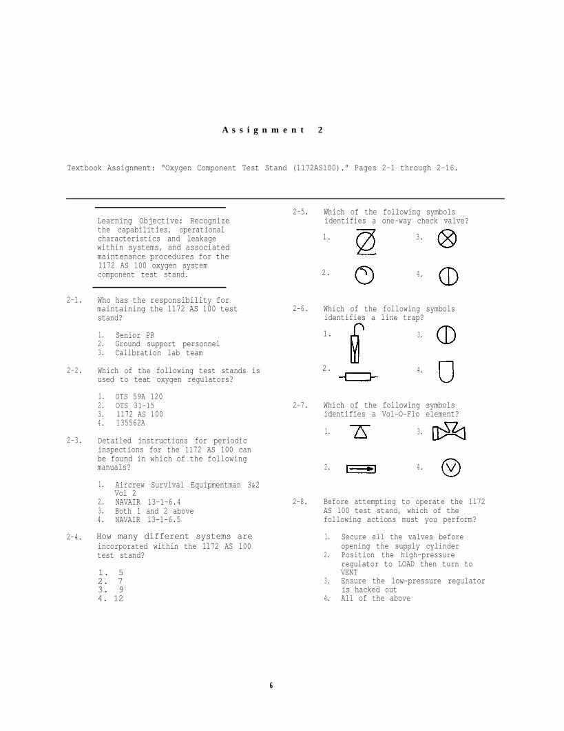
A s s i g n m e n t 2
Textbook Assignment: “Oxygen Component Test Stand (1172AS100).” Pages 2-1 through 2-16.
1. 3.
2.
2-1.
2-2.
2-3.
2-4.
Learning Objective: Recognizethe capabilities, operationalcharacteristics and leakagewithin systems, and associatedmaintenance procedures for the1172 AS 100 oxygen systemcomponent test stand.
Who has the responsibility formaintaining the 1172 AS 100 teststand?
1. Senior PR2. Ground support personnel3. Calibration lab team
Which of the following test stands isused to teat oxygen regulators?
1. OTS 59A 1202. OTS 31-153. 1172 AS 1004. 135562A
Detailed instructions for periodicinspections for the 1172 AS 100 canbe found in which of the followingmanuals?
1.
2.
1.
2.3.4.
Aircrew Survival Equipmentman 3&2Vol 2NAVAIR 13-1-6.4Both 1 and 2 aboveNAVAIR 13-1-6.5
How many different systems areincorporated within the 1172 AS 100test stand?
1. 52. 73. 94. 12
2-5.
2-6.
2-7.
2-8.
Which of the following symbolsidentifies a one-way check valve?
4.
Which of the following symbolsidentifies a line trap?
3.
4.
Which of the following symbolsidentifies a Vol-O-F1o element?
1. 3.
2. 4.
Before attempting to operate the 1172AS 100 test stand, which of thefollowing actions must you perform?
1. Secure all the valves beforeopening the supply cylinder
2. Position the high-pressureregulator to LOAD then turn toVENT
3. Ensure the low-pressure regulatoris hacked out
4. All of the above
6

2-9.
2-10.
2-11.
2-12.
2-13.
2-14.
During which leakage test is supplynitrogen pressure tested for leakage?
1. Inward leakage2. Outward leakage3. Rotameter leakage4. Differential leakage
How often do you perform the outwardleakage test?
1. Daily2. Biweekly3. Weekly4. Monthly
To test for leakage on the supplypressure gage, you should pressurizethe gage and wait 2 minutes. Howmuch leakage, if any, is allowed?
1. 5 psi2. 10 psi3. 15 psi4. None
What is the minimum pressure range of theregulated high-pressure system?
1. 0 psig2. 100 psig3. 250 psig4. 500 psig
The gage guard that protects thelow-range and high-range leakagerotameters is set to relieve at whatmaximum pressure?
1. 50 ± 5 psig2. 170 ± 5 psig3. 180 ± 5 psig4. 250 ± 10 psig
Which of the following gagesindicates the gage guard pressurethat protects the low-range andhigh-range rotameters?
1. Regulated low-pressure gage2. Regulated high-pressure gage3. Supply gage4. Differential pressure gage
2-15. When testing the regulated
2-16.
2-17.
2-18.
2-19.
high-pressure system, you determinethat there is a leak in one of yourON/OFF valves. The leak will beindicated on which of the followinggages?
1. N2 inlet pressure gage2. N2 outlet pressure gage3. Differential pressure gage
To bleed the regulated high-pressuresystem, you should use which of thefollowing valves or regulators?
1. High-pressure regulator only2. System bleed valve only3. Both 1 and 2 above4. Inlet bleed valve
To check the regulated high-pressuresystem for leaks, you should turn thesupply cylinder ON. This pressurecan be read on which of the followinggages?
1. Low-pressure gage2. High-pressure gage3. Both 1 and 2 above4. Differential pressure gage
When testing the high pressure systemfor leaks, what period of time mustyou wait before reading and rereadingthe high-pressure gage?
1. 1 min2. 2 min3. 3 min4. 5 min
What is the minimum pressure range ofthe regulated low-pressure nitrogensystem?
1. 0 to 180 psig2. 0 to 250 psig3. 0 to 500 psig4. 0 to 1800 psig
Learning Objective: Identify thetest stand used to test LOX con-verters, test stand inspections,internal parts, and generalmaintenance.
7

2-20. The purpose of the regulatedlow-pressure nitrogen system is tosupply nitrogen to which of thefollowing components?
1. N2 input connection2. In-system leakage rotameters3. Both 1 and 2 above4. N2 output connection
2-21. When you are testing the regulatedlow-pressure system for leaks, whataction determines a leak is present?
1. The low-pressure gage drops2. The low-pressure gage rises3. The ball in the high-range
leakage rotameter rises4. The ball in the low-range leakage
rotameter rises
2-22. When the low-pressure regulatorindicates 160 psig, what should theN2 input pressure gage be reading?
1. 70 psig2. 120 + 5 psig3. 145 ± 5 psig4. 160 psig
2-23. When making bleed adjustments to a20004 miniature regulator, You shoulduse which of the following systems?
1. Input2. Rotameter3. output4. Regulated low-pressure
2-24. How many rotameters are incorporatedin the rotameter system?
1. One2. Two3. Three4. Four
2-25. Which of the following types ofleakage tests requires you to connectthe low-pressure connection (19) andthe 200 ccm leakage connection (20)together by using the line with twobayonet fittings?
1. Leakage between the low-pressureand rotameter system
2. Leakage between the high-pressureand rotameter system
3. Leakage through the leakagecontrol valve (E)
4. Leakage through the supplyshut off valve
2-26. Which of the following connections isNOT located inside the pressurechamber?
1. Low-pressure connection2. 200-ccm leakage connection3. Reference tap connection4. Differential pressure connection
2-27. To pressurize the differentialpressure system for a leakage test,you open the leakage control valveuntil it reaches how many inches ofwater on the pressure/suctionmanometer?
1. 5 in.2. 9 in.3. 12 in.4. 18 in.
2-28. Leakage in the differential pressuresystem will be indicated on which ofthe following gages?
1. Pressure/auction rotameter2. High-range leakage rotameter3. Low-pressure leakage rotameter4. All of the above
2-29. The differential pressure indicatingsystem is used to perform which ofthe following tests?
1. Safety-pressure2. Pressure breathing3. Flow suction4. All of the above
2-30. How many manometers are used on thetest stand to indicate differentialpressure?
1. One2. Two3. Three4. Four
2-31. Which of the following valves orconnections affect(s) readings on thepressure suction manometer?
1. Helmet reference tap2. Suit simulator reference tap3. Pressure equalizer valve4. All of the above
8

2-32.
2-33.
2-34.
2-35.
2-36.
2-37.
1.0 psig is equal to how many inchesof H20?
1. 8.52. 9.03. 20.04. 27.7
1.0 psig is equal to how many inchesof HG?
1. 5 in.2. 2 in.3. 3 in.4. 4 in.
To test the differential pressureindicating system, you must applymany inches of H20 to the system?
1. 16 in.2. 18 in.3. 20 in.4. 24 in.
how
Pressure applied to the differentialpressure system can be read on whichof the following component?
1. Pressure/suction manometer2. High-pressure gage3. Low-pressure gage4. Inclined flowmeter
Leakage in the differential pressuresystem will be indicated on which ofthe following components?
1.2.3.4.
High-range flowmeterLow-range flowmeterBoth 1 and 2 abovePressure/suction manometer
How should you bleed the differential
pressure system?
1. Back out on the low-pressureregulator and open the bleedvalve
2. Back out on the high-pressureregulator and open the bleedvalve
3. Turn in on the low-pressureregulator and open the bleedvalve
4. Turn in on the high-pressureregulator and open the bleedvalve
2-38. Which of the following systems is
2-39.
2-40.
2-41.
2-42.
2-43.
2-44.
considered the heart of the teststand?
1. Vacuum system2. Differential system3. Rotameter system4. Nitrogen system
Which of the following valves allowsa direct evacuation of the chamber?
1. Cutput valve2. Vacuum control valve3. Bypass valve
Which of the following valves draws aflow through the item under test?
1. Output valve2. Vacuum valve3. Input valve
The vacuum system is checked at whichof the following altitudes?
1. 5,000 feet2. 10,000 feet3. 20,000 feet4. 50,000 feet
Atmosphere, as a unit of pressure, isequal to what total number of poundsper square inch?
1. 6.92. 12.53. 14.694. 27.0
At what altitude do you perform theleakage test of the altitude sensingsystem?
1. 10,000 feet2. 20,000 feet3. 50,000 feet4. 150,000 feet
To indicate a leak is present whentesting the chamber bleed system forleaks, you will receive a drop in
1. supply pressure2. regulated low pressure3. regulated high pressure4. altitude
9

2-45. Which of the following systems is thelargest and most important system inthe operation of the 1172 AS 100 teststand?
1. Vacuum2. System bleed3. Flow measuring4. Differential pressure
2-46. Where does the output flow systemoriginate?
1. Prizometer2. Flow selector valve3. Vol-O-Flow element
2-47. Output flow systems can be used onlywith the chamber at altitude.
1. True2. False
2-48. The input flow system originates atthe
2-49. Which of the following systemsoriginates at either the vent ambientvalve or the vent pressure valve?
1. Vent flow2. Differential pressure3. Vol-O-Flow4. Bleed
2-50. To use the flow measuring system, youmust convert liters-per-minute towhich of the following measurements?
1. In. H202. Psig3. In. Hg
2-51. At what altitude & you perform theleak test for the flow measuringsystem?
1. Sea level2. 5,000 feet3. 10,000 feet4. 15,000 feet
1. prizometer2. flow selector valve3. suit simulator4. air intake
10
A s s i g n m e n t 3
Textbook Assignment: “Carbon Dioxide Transfer Equipment.” Pages 3-1 through 3-13.
3-1.
3-2.
3-3.
3-4.
Learning Objective: Relativeto C02 transfer equipment,recognize their components,construction and operatingfeatures, and servicing andmaintenance procedures,including the replacement ofpackings and safety disc.
Which of the following companiesmanufacture(s) CO2 transfer pumps?
1. C-O-Two Fire Equipment2. Walter Kidde3. Both 1 and 2 above4. Bendix Engineering
Which of the following methods is usedto take up any slack in the drive belton a SC-5 CO2 transfer unit?
1. Adjust the adapter on the drivepully
2. Slide the motor on the adjustablebase
3. Replace the drive belt4. Adjust the drive shaft
The SC-5 CO2 pump is designed to workwith a pressure of how many pounds persquare inch?
1. 20002. 27503. 30004. 3500
The SC-5 CO2 Transfer pump willtransfer approximately how many poundsof CO2 out of a full supply cylinder?
1. 38 lb2. 50 lb3. 80 lb4. 100 lb
3-5.
3-6.
3-7.
3-8.
3-9.
How many pounds of CO2 are there in astandard supply cylinder?
1. 38 lb2. 40 lb3. 50 lb4. 100 lb
The SC-5 pump has a flanglble safetydisc that is designed to releasepressure in the pump at what maximumpressure range?
1. 2050 to 2100 psig2. 2250 to 2300 psig3. 2500 to 3000 psig4. 2650 to 3000 psig
What prevents any recoil in the eventthe safety disc ruptures?
1.2.3.4.
Recoil valveSafety valveSafety disc nutDefuser
The SC-5 CO2 pump requires which ofthe following types of oil?
1. 10 W 402. 10 W 303. SAE 204. SAE 30
Which of the following motors isstandard equipment on the SC-5 transferunit?
1. 1/2 horsepower2. 1 horsepower3. 1 1/2 horsepower4. 2 horsepower
11

3-10.
3-11.
3-12.
3-13.
3-14.
3-15.
3-16.
When adding oil to the SC-5 CO2
transfer pump that does not have adip stick, you should fill thecrankcase with oil to what level?
1. One-eighth of an inch from the topof the cup
2. One-fourth of an inch from the topof the cup
3. To the fourth thread4. To the first thread
Other than the crankcase, how manydifferent lubrication points arerequired on the SC-5 transfer unit?
1. One2. Two3. Three4. Four
When lubricating the idler gear and thepuny shaft, you should use what type oflubricant?
1. SAE 20 oil2. SAE 30 oil3. Vaseline4. Light cup grease
Motor bearings contain enough grease tokeep the bearings lubricated forapproximately how long?
1. 1 year2. 2 years3. 30 days4. 6 months
If it is necessary to wire the SC-5CO2 pump for 220 power, where can youfind information on the wiring diagram?
1. In NAVAIR 13-1-6.12. In NAVAIR 13-1-6.23. In OPNAV 5510.1E4. On the pump’s nameplate
If you are required to change theelectrical plug on a SC-5 CO2 unit, theground wire is which of the followingcolors?
1. Red2. Green3. White
Carbon dioxide is stored under (a) whatpressure and (b) at what temperature?
1. (a) 850 psig (b) 70°F2. (a) 1800 psig (b) 70°F3. (a) 2900 psig (b) 60°Fb. (a) 3000 psig (b) 60°F
3-17. What is the purpose for running-in a
3-18.
3-19.
3-20.
3-21.
3-22.
3-23.
new pump or one that has been idle for along time?
10 To check for lubrication2. To check for leaks of CO2
3. To loosen the bearing packings4. To tighten the bearing packings
Which of the following wrenches is usedto tighten fittings and connections onthe C-O-Two unit?
1. A 10-inch wrench2. A 12-inch wrench3. A pipe wrench (13 inches)4. A crescent wrench (13 inches)
Which of the following statementsconcerning a supply cylinder is NOTtrue?
1. A supply cylinder weighs 50 pounds2. The maximum capacity of a supply
cylinder is 50 pounds3. 10 pounds of the contents may be
gaseous4. 40 pounds of the contents may be
liquid
A cool supply cylinder will transfer itscontents more efficiently than a warmone.
1. True2. False
The time required to charge an emptycylinder increases with increasedtemperature of the cylinder.
1. True2. False
A large cylinder will recharge faster ifit is placed in an upright position.
1. True2. False
To prevent expansion of CO2 in thesupply hose, the valve should have anopening of at least
1. 1/8 inch2. 1/4 inch3. 3/4 inch4. 1 inch
12

3-24. How often is the idler shaft lubricated?
1. Every 30 days2. Every 6 months3. Every year4. Every 2 years
3-25. Gear teeth should be lubricated with
1. a thin coating of light cup grease2. a thick coating of light cup grease3. SAE 30 motor oil4. a thin coating of Vaseline
3-26. The piston rod should be lubricatedevery 6 months with a light coating of
1. light cup grease2. Vaseline3. gear grease4. SAE 30 motor oil
3-27. What should you use to clean the motorcommutator on the Sc-5 CO2 traneferunit?
1. A dry piece of lint-free cloth2. A piece of cloth dipped in dry
cleaning solvent3. Freon Type II4. Freon Type I
3-28. How often should you change the oil inthe crankcase of the Sc-5 CO2 transferpump?
1. Every 10 days2. Every 21 days3. Annually4. Every 2 years or biannually
3-29. What procedure must you use to lubricatethe bearing housing on the electricmotor?
1. Use a grease gun2. Disassemble the complete unit3. Disassemble the bearing housing
3-30. The electric motor bearings should belubricated every 2 years. Beforelubricating the bearings, you shouldclean them with
1. carbon tetrachloride2. toluene3. Stoddard solvent4. dry cleaning agent
3-31. How much grease should you apply to eachbearing?
1. 1 or 2 shots of light cup grease2. Add grease until it flows freely
from grease cups3. One-half ounce of grease4. 1 ounce of grease
3-32. Wnen should you replace the piston rodpacking on the SC-5 transfer pump?
1. Every 250 operating hours2. Every 500 operating hours3. Yearly4. Every 2 years
3-33. What is the purpose of the flanged-typepacking nut?
1. It serves only to hold the peckingin place
2. It is used to reduce leaks in thepacking
3. It is used as an adjustment forproper CO2 pressure
3-34. The Walter Kidde transfer unit comeswith which of the following motors?
1. One-fourth horsepower2. One-half horsepower3. Three-fourths horsepower4. 1 horsepwer
3-35. The safety disc used in the Walter Kiddepumps has a range of
1. 2500 to 2750 psi2. 2650 to 3000 psi3. 2750 to 3000 psi4. 2900 to 3000 psi
3-36. The motor for the Walter Kidde transferunit operates at
1. 550 rpm2. 1500 rpm3. 1750 rpm4. 2000 rpm
3-37. The multibreaker on the Walter Kiddeunit is designed to protect the unit.It operates on what total number ofamperes?
1. 5 amp2. 15 amp3. 20 amp4. 30 amp
13

3-38. How is the multibreaker reset on aWalter Kidde unit?
1. By replacing the blown fuse2. By reseting the breaker box3. By turning the ON/OFF switch to OFF
then to ON
3-39. Which motor oil is used in the crankcaseof the Walter Kidde unit?
1. SAE 10 W 402. SAE 103. SAE 204. SAE 30
3-40. Which of the following directive takeprecedence over the procedures outlinedin the manufacturer manual?
1. OPNAV2. NAVAIRSYSCOM3. 4790.2B
3-41. What size wrench is recommended byWalter Kidde to tighten connectingjoints?
1. 6 in.2. 8 in.3. 10 in.4. 12 in.
3-42. How often should you change the oil inthe Walter Kidde crankcase?
1. After 150 hours of operation2. After 500 hours of operation3. Every year4. Every 2 years
3-43. How much oil does the Walter Kiddecrankcase hold?
1. 1 pint2. 2 pints3. 1 quart4. 2 quarts
3-44. If a leak should develop at the lowerend of the plunger on the Walter Kiddeunit, what type of tool should you useto correct the problem?
3-45. The ICC requirement for testing aCO2 cylinder requires that the cylinderbe tested at what pressure?
1. Twice the working pressure2. Three times the working pressure3. Five-thirds the working pressure
3-46. How often should a cylinder behydrostatically tested?
1. Every 5 years2. Every 2 years3. Every 3 years4. Every 7 years
3-47. Winterized extinguishers can beidentified by
1. yellow dots three-fourths of an inchon opposite sides of each other
2. one three-fourths of an inch yellowdot on the shoulder of the cylinder
3. two black dots4. a 1-inch yellow band
3-48. How much nitrogen is required towinterize a CO2 cylinder?
1. 100 psi2. 200 psi3. 300 psi4. 400 psi
3-49. What maximum temperature can awinterized cylinder be subjected towithout rupturing the safety disc?
1. 80°F2. 110°F3. 150°F4. 160°F
3-50. To replace a safety disc on F/U-6/Pcylinder, you need a torque wrench, afive-sixteenth inch socket and a
1. piece of hex stock 5/16 x 2 inches2. 3/8 x 6 inches rod3. 1/2 x 6 inches rod
1. A special rod approximately3/8 inch x 6 inches
2. A special rod approximately1/2 inch x 6 inches inches
3. A one-half inch box end wrench4. A three-eighths inch box end wrench
14
A s s i g n m e n t 4
Textbook Assignment: “Sewing Machine Repair.” Pages 4-1 through 4-37.
4-1.
4-2.
4-3.
4-4.
Learning Objective: Recognizemaintenance responsibilities introubleshooting, repairing, andreplacing parts of the Class 111sewing machine.
The single needle, rotary axis 111 W 155sewing machine makes which of thefollowing federal standard stitches?
1. 1032. 2003. 3014. 400
Which of the following sewing machines isNOT suited for sewing medium-heavyfabrics?
1. Singer 111 W 1552. Juki LU-5623. Consew 2254. Singer 31-15
The 111 W 155 sewing machine features arotary axis; to what component does thisterm apply?
1. Safety clutch2. Arm shaft3. Sewing hook4. Feed eccentric
The feeding action of the 111 W 155sewing machine allows which componentsto move in unison?
1. The lifting presser foot, thepinion gear, and the feed dogs
2. The vibrating presser, the needle,and the feed dogs
3. The lifting presser, the needlebar,and the feed dogs
4. The vibrating presser, the liftingpresser, the needle, and the feeddogs
4-5.
4-6.
4-7.
4-8.
4-9.
The 111 W 155 sewing machine may beoperated to what maximum number ofstitches per minute (SPM)?
1. 22002. 28003. 35004. 4000
The 111 W 155 sewing machine has a stitchper inch (SPI) range of
1. 3 1/2 to 302. 5 to 323. 3 1/2 to 324. 5 to 30
What component holds the material as theneedle is raised and moves forward foranother bight?
1. Feed dogs2. Vibrating presser3. Feed eccentric4. Lifting presser
In which direction will the 111 W 155sewing machine move the fabric beingsewed?
1. Toward the operator2. Away from the operator3. Either toward or away from the
operator, depending on the settingof the feed drive eccentric
The 111 W 151 sewing machine has astitch per inch (SPI) range of
1. 3 1/2 to 302. 5 to 323. 3 1/2 to 324. 5 to 30
15
4-10. What is the maximum presser foot liftfor the 111 W 155 sewing machine?
1. One-half in.2. One-eighth in.3. Three-fourths in.4. Three-sixteenths in.
4-11. What is the maximum presser foot lift forthe 111 W 151 sewing machine?
1. One-half in.2. Three-eighths in.3. Three-fourths in.4. Three-sixteenths in.
4-12. The 111 W 155 and 111 W 151 are similarIn most features EXCEPT that the111 W 151 has only one
1. feed drive eccentric2. presser foot3. oiling point4. feed dog
4-13. An accumulation of dust and lint willcause the same sluggish operation problemas a loose puny belt.
1. True2. False
4-14. New sewing machines should be cleaned toremove corrosion preventive substancesthat were applied at the factory. Whatsubstance is used to remove corrosionpreventive substances?
1. Stoddard solvent2. Freon 1133. Diesel fuel4. JP-5
4-15. After using a sewing machine, you shouldclean and oil it.
1. True2. False
4-16. Compressed air should never be used toclean a sewing machine.
1. True2. False
4-17. An excessive amount of oil on the workingparts of any sewing machine will probablyresult in which of the followingconditions?
1. The oil will dry out and cause greaseto form on friction surfaces
2. The oil will drip on materials beingsewn and soil the project
3. The oil will accumulate in the drippan and overflow on the drive motor
4. The oil will cause condensation thatwill drip into the drive motor
4-18. Hard to reach places on the sewingmachine may be cleaned with
1. a medium soft bristle brush only2. low pressure air only3. a medium soft bristle brush and
low pressure air
4-19. At what minimum interval should sewingmachines be given a through cleaning andoiling?
1. Every 3 mo2. Every 6 mO3. Every 12 mo4. Every 18 mo
4-20. A clean dust cloth should be used toclean all sewing machine parts EXCEPTthe
1. head2. oil pan3. motor casing4. arm shaft
4-21. If unable to obtain the recommended typesof oil required by the manufacturer, youmay use which of the following oils as asubstitute?
1. Cod oil2. Turbine oil3. Mineral oil4. STP oil treatment
4-22. Continual malfunction of a sewing machineis most likely caused by which of thefollowing conditions?
1. Electrical lead unplugged2. Out of timing sequence3. Lack of lubrication4. Drive motor wired backwards
16
Complete disassembly of the 111 W 1554-23.
4-24.
4-25.
4-26.
4-27.
4-28.
sewing machine is necessary to properlyset the timing sequence.
1. True2. False
When the arm shaft is timed with the hookdrive shaft, it is necessary to turn thebalance wheel toward the operator untilwhich of the following components reachesits highest position?
1. Bell crank2. Needlebar3. Thread take-up lever4. Drive belt
In timing the arm shaft with the hookdrive shaft, you must align the timingmark on the timing plate with the timingmark on which of the followingcomponents?
1. Hook drive shaft2. Arm shaft3. Feed drive shaft4. Pinion gear
After timing the arm shaft with the hookdrive shaft, you should perform whichof the following actions?
1. Set the hook to the needle2. Install the connection belt pulley3. Set the feed dogs4. Install the motor drive belt
Centering the feeding action on the111 W 155 sewing machine isaccomplished by ensuring that thefeed dogs do NOT strike the throatplate.
1. True2. False
Which of the following actions prevent(s)the needle from wandering from side toside?
1. Ensuring the needlebar rock framehinge stud is tight
2. Ensuring the needlebar rock frameguide bracket is tight
3. Both 1 and 2 above4. Ensuring the needlebar is properly
timed and tight
4-29. To set the 111 W class sewing machine to
4-30.
4-31.
4-32.
4-33.
4-34.
its maximum stitch length, which of thefollowing actions is required?
1. Depress the plunger and turn thebalance wheel toward the operator
2. Depress the plunger and turn thebalance wheel away from the operator
3. Push the stitch regulator lever allthe way down
4. Push the stitch regulator lever allthe way up
Which of the following actions allowsyou to adjust the movement of the feeddogs?
1. Loosen the feed dog fork2. Loosen the feed driving crank pinch
screw3. Remove the throat plate4. Remove the feed driving cam
To time the sewing hook and theneedlebar on the sewing machine, youshould remove which of the followingparts?
1. Throat plate2. Feed dogs3. Presser foot4. All of the above
Which of the following methods shouldyou use to adjust the hook guard?
1. Loosen the two screws and move thehook guard left or right
2. Move the adjusting screw clockwise3. Bend the hook guard washer
Which of the following parts preventsthe needle from striking the sewinghook ?
1. Safety clutch2. Hook gib3. Hook guard4. Hook pinion gear
Which of the following parts controlsthe feeding motion provided by thealternating pressers?
1. Feed driving cam2. Feed driving rock shaft3. Pressure lifting cam4. Pressure lifting eccentric
17
4-35. When timing the pressure liftingeccentric, you should set the sewingmachine at
1. 3 1/2 SPI2. 5 SPI3. 8 SPI4. 32 SPI
4-36. What is the purpose of the threadcontroller spring?
1. It prevents the bobbin threadfrom breaking
2. It prevents the upper threadfrom breaking
3. It prevents the sewing hookfrom piercing the thread
4. It prevents the needle frompiercing the thread
4-37. Which of the following statementsconcerning the thread controllerspring is correct?
1. It rests on the thread controllerspring stop as the point of theneedle enters the material
2. It rests on the thread controllerspring stop as the needle reachesits highest point
3. It prevents the bobbin thread fromjamming under the throat plate
4-38. When adjusting the thread tension andyou cannot properly adjust it with theupper thread tension disc, what actionshould you take?
1. Change the size of thread2. Change the needle size3. Adjust the bobbin tension4. Adjust the presser foot tension
4-39. If your machine is hard to turn afteryou time and adjust it, which of thefollowing actions must be performedfirst?
1. Check the feeding action2. Remove the arm shaft connection belt3. Remove the throat plate and set the
stitches to zero
Learning Objective: Identifythe functions, adjustments,timing and general maintenanceapplicable to the 31-15 sewingmachine.
4-40. Which of the following is an oscillatingtype sewing machine?
1. 31-152. 331K13. Consew C-304. Each of the above
4-41. The 31-15 sewing machine will sewcanvas up to
1. 4 oz2. 6 oz3. 8 oz4. 10 oz
4-42. What is the stitch range on the ConsewC-30?
1. 5 to 30 SPI2. 7 to 32 SPI3. 5 to 27 SPI4. 7 to 27 SPI
4-43. What is the clearance between thepresser foot and the throat plate atthe 31-15 sewing machine?
1. One-fourth in.2. One-eighth in.3. Seven-sixteenths in.4. Five-sixteenths in.
4-44. Which of the following is the maintiming point on a 31-15 sewing machine?
1. Hook drive gear2. Hook pinion gear3. Needlebar4. Balance wheel
4-45. When you set the needlebar and it startsits upstroke, what is the distance ofthe hook in relation to the eye of theneedle?
1. One-sixteenth inch above2. One-sixteenth inch below3. One-eighth inch above4. One-eighth inch below
4-46. To set the feeding action on a 31-15sewing machine, you must loosen whichof the following screws?
1. Feed dogs setscrew2. Feed dog cam fork setscrew3. Feed-driving rock shaft crank pinch
screw4. Feed-driving rock shaft connection
pinch screw
18

Learning Objective: Recognizethe procedures for disassemblingand assembling the 111 W 155sewing machine.
4-47. You may have to grind off the casehardening surface on a sewing machinescrew before you can remove it with aneasyout.
1. True2. False
4-48. Which of the following screws has aleft-hand thread?
1. Balance wheels retaining screw2. Arm shaft connection setscrew3. Feed eccentric adjusting screw4. Thread take-up lever retaining
screw
4-49. Which of the following screws is looseneda quarter of an inch and is NOT to beremoved when you dissemble the 111 W 155sewing machine?
1. Presser bar spring setscrew2. Presser bar spring support screw3. Vibrating presser bar connecting
screw4. Presser lifting link crank pinch
screw
4-50. If binding should occur while removingthe presser bar, what action shouldyou take?
1. Apply a light oil coating2. Turn the presser bar slowly with a
back and forth motion3. Both 1 and 2 above4. Insert a screw driver into the
lower slot of the presser barwhile applying an upward motionon the presser
4-51. When you remove the presser bar, whichof the following parts will fall off?
1. Presserbar spring bracket2. Releasing bracket3. Guide lever4. All of the above
4-52.
4-53.
4-54.
4-55.
4-56.
4-57.
4-58.
Which of the following parts preventsside to side movement of the needlebarrock frame?
1. The needlebar support bracket2. The needlebar hinge bracket3. The needlebar rock frame position
bracket4. The needlebar rock frame hinge
bracket
Which of the following parts eliminatesend play in the balance wheel and armshaft?
1. Balance wheel adjusting screw2. Arm shaft shim3. Balance wheel shim4. Arm shaft bushing
Which of the following parts transfersthe motion from the arm shaft to theneedlebar?
1. The needlebar rock stand2. The needlebar driving shaft3. The needlebar rock shaft4. The needlebar driving stud
What is used to remove the needlebarcrank friction washer from the sewingmachine after you remove the arm shaft?
1. Allen wrench2. Needle nose pliers3. Index finger4. Spanner wrench
Which of the following parts controlsthe feeding mechanism of the sewingmachine?
1. Feed driving eccentric2. Safety clutch3. Feed lifting eccentric4. Feed drive gear
Which of the following parts convertsthe longitudinal motion of the hookdriving shaft to the horizontal motionof the sewing hook?
1. Hook saddle assembly2. Hook pinion gear3. Hook driving gear4. Hook drive eccentric
What part allows the thread to passbetween the bobbin case and the throatplate?
1. The bobbin case opener2. The thread take-up lever3. The thread controller spring4. The bobbin case gib
19

4-59. Before reassembling a sewing machine,what do you use to smooth rusty parts?
1. Sand paper2. Rubbing compound3. Emery paper4. Grinding compound
4-60. When reassembling a sewing machine,what part should you install first?
1. Arm shaft2. Hook drive shaft3. Bobbin case opener4. Hook saddle assembly
4-61. When the bobbin case opener is properlyinstalled, it is in what position?
1. The curved end points toward thebobbin case
2. The curved end points away fromthe bobbin case
3. The blunt end points toward thebobbin case
4. The blunt end points away fromthe bobbin case
4-62. What total number of spline grooves areon a hook driving shaft?
1. Five2. Six3. Seven4. Eight
4-63. On the hook driving shaft, the end witha spline is installed first into theright hook driving shaft bearing.
4-64. When you are replacing the feed-drivingeccentric, which of the followingstatements is true?
1. The oiling felt faces down and thecrank toward the operator
2. The oiling felt faces up and thecrank toward the operator
3. The oiling felt faces up and thecrank away from the operator
4. The oiling felt faces down end thecrank away from the operator
4-65. When you are installing the hook drivingshaft lock ratchet, the flange andsetscrews face the left of the machine.
1. True2. False
4-66. Before you insert the needlebar rockframe assembly, the needlebar connectinglink must be at its lowest position.
1. True2. False
4-67. When installing the presser bar into themachine head, you should insert itthrough the upper bushing about
1. 1 inch2. 2 inches3. 3 inches4. 3 1/2 inches
1. True2. False
20

A s s i g n m e n t 5
Textbook Assignment: “Aircrew Survival Equipment Training.” Pages 5-1 through 5-42.
Learning Objective: Relativeto sea survival, recognize theproper survival equipment, useof life preservers and liferafts, and bailout proceduresover water using four-linerelease.
5-1.
5-2.
5-3.
5-4.
5-5.
During the Southeast Asian conflict, whatwas the average rescue time for a downedaircrewman?
1. 6 hours2. 8 hours3. 24 hours4. 48 hours
What is the most important factor inbringing downed aircrewmen home alive?
1. New survival equipment2. The will of the aircrewman to live3. Air support for search and rescue
(SAR)
Which of the following manuals coverssearch and rescue (SAR)?
1. NAVAIR 13-5-5012. NAVAIR 13-1-6.23. NWP 19-14. NWP 13-1
Which of the following manuals coverssurvival techniques?
1. NAVAIR 00-8OT-1O12. NAVAIR 00-80T-2013. NAVAIR 00-80T-5014. NAVAIR 00-80T-601
General information about aircrew person-nel protection equipment and training canbe found in which of the followingmanuals?
1. OPNAV 4790.2B2. OPNAV 4790.2C3. OPNAV 3710.74. OPNAV 5100
5-6.
5-7.
5-8.
5-9.
5-10.
5-11.
5-12.
As a PR, one of your jobs is to teachswimming to aircrewmen.
1. True2. False
During a survival situation, panic willbe your worst enemy.
1. True2. False
The anti-g suit is an excellent flotationdevice.
1. True2. False
The primary flotation device for enaircrewman flying in a VA type aircraftis which of the following?
1. LPU2. LPP3. Mk-24. Mk-3C
Which of the following life preservers isused by maintenance personnel?
1. LPU2. LPP3. Mk-14. Mk-3
Which of the following preserver may beused as a substitute for the LPP lifepreserver?
1. LPU-30/P2. Mk-33. LPU
Which of the following life preserveris worn by personnel flyingejection-seat-equipped aircraft?
1. LPA-2A2. LPU-21B/P3. LPU-24A/P4. LPP
21

5-13. The FLU-8A/P is installed on which ofthe following life preservers?
1. LPU-21B/D2. LPU-23A/P3. LPU-24A/P4. Both 2 and 3 above
5-14. After life preservers are activated theyinflate to their designed shape withinwhat total number of seconds?
1. 102. 203. 304. 60
5-15. The LPP life preserver provides the userwith a buoyance of how many pounds?
1. 222. 293. 354. 65
5-16. The FLU-8A/P will work only in sea water.
1. True2. False
5-17. The FLU-8A/P system is used as a backupsystem for the manual release.
1. True2. False
5-18. Partial inflation of the collar lobe onthe LPA and LPU has been a reportedproblem.
1. True2. False
5-19. The NB-8 parachute harness is worn overthe LPA life preserver.
1. True2. False
5-20. The four-line release system is designedto reduce oscillation.
1. True2. False
5-21. The four-line release should NOT be usedif your canopy has any evident damageafter opening.
5-22. It takes approximately how much force toactivate the four-line release?
1. 10 pounds2. 20 pounds3. 30 pounds4. 60 pounds
5-23. To select the proper life raft for anaircraft, which of the followingallowance lists should you use?
1. NAVSUP 1012. NAVSUP 20023. NAVAIR 00-35-QA-14. NAVAIR 00-35-QH2
5-24. What is the length of an LPI life raftwhen it is fully deployed?
1. 4 feet2. 5 feet3. 6 feet4. 7 feet
5-25. What should you use to right anoverturned LR1 life raft?
1. The righting handles on the sidesof the raft
2. The righting lanyard attached tothe CO2 bottle3. The boarding handles on theflotation tube
5-26. If the life raft is on the crest of awave, a properly adjusted sea anchorwill be in what position?
1. In the trough of the wave2. Resting in the wave3. 10 feet from the life raft4. 12 feet from the life raft
5-27. Which of the following life rafts isdesigned to carry four survivors?
1. LRU-12/A2. LRU-13/A3. LRU-14/A4. LRU-15/A
5-28. An LR-12/A life raft has how manyseparate inflatable compartments?
1. One2. Two3. Three4. Pour
1. True2. False
22

5-29.
5-30.
5-31.
5-32.
5-33.
5-34.
5-35.
Which of the following flotationcompartments is/are inflated by CO2?
1. Bow2. Stern3. Both 1 and 2 above4. Seat
when using the hand pump to top off thepressure on an LRU-12/A life raft, howfar should you open the topping-offvalve?
1. 1 turn2. 1 1/2 turns3. 2 turns4. Fully open
If there is a tear in the bow section ofan LPU-12/A life raft, what, if anything,would prevent it from sinking?
1. Quick patch kit supplied with theraft
2. Double lined flotation walls3. The internal bulkheads4. Nothing
To board the LRU-12/A, which of thefollowing procedures is meet correct?
1. Board it from the bow using theboarding line
2. Board it from the sides using theboarding handles
3. Board it from the stern using thestirrup
Which of the following life rafts has acircular flotation tube?
1.2.3.4.
LRU-12/ALRU-13/ALRU-14/ALRU-15/A
Who has the responsibility for installingthe equalizer clamp?
1. First person aboard2. Last person aboard3. Senior man aboard
What is the purpose of the equalizerclamp?
1. To prevent CO2from escaping2. To prevent the raft from deflating
in the event a hole is present3. To prevent overpressurization of
flotation tubes
5-36. When you are tying three or more LRU-15/Alife rafts together, which of thefollowing statements is true?
1. Tie the rafts 180° apart from thepivot raft
2. Tie all the rafts’ bows to the stern3. Tie the rafts 50 feet apart
5-37. What is the recommended distance betweenlife rafts that are tied together?
1. 8 feet2. 25 feet3. 50 feet4. 100 feet
5-38. Never eat any food unless an adequateamount of water is available.
1. True2. False
5-39. Never tie fish to the side of your raft.
1. True2. False
5-40. Always secure yourself to your life raft.
1. True2. False
5-41. In rough seas it is permissible to makea sea anchor out of a signaling panel.
1. True2. False
5-42. A person can survive without water forwhat period of time?
1. 12 days2. 14 days3. 3 days4. 6 days
5-43. A person can go without food for whatperiod of time?
1. 14 days2. 21 days3. 30 days4. 40 days
5-44.surf, which of the following iS a truestatement?
1. Tie the sea anchor to the bow2. Trail the sea anchor from the stern3. Make your landing stern first
When you are rafting ashore in heavy
23
Learning Objective: Identifyrescue devices used by aircrewmenand helicopter rescue. Identifysearch and rescue (SAR) communi-cation modes.
5-45.
5-46.
5-47.
5-48.
5-49.
5-50.
Which of the following is the primaryrescue device?
1. Rescue hook2. Rescue sling3. Gated D-ring
At what maximum number of pounds is thesmaller hook on the double rescue hookrated?
1. 500 pounds2. 1000 pounds3. 1500 pounds4. 2000 pounds
Which of the following statementsconcerning the double rescue hook ismost correct?
1. Use only the large hook to hoistpersonnel
2. Use only the smaller hook to hoistpersonnel
3. You can hoist personnel with eitherhook
As a survivor, why must you never touchany rescue device being lowered from ahelicopter until it has touched thewater?
1. To prevent electrical chock fromstatic electricity
2. To prevent development of cramps3. To prevent your raft from capsizing
Horse collar is another name for therescue strop.
1. True2. False
A crewman being rescued by a helicoptershould assist the helo crew by swinginginto the helo feet first.
1. True2. False
5-51. The forest penetrator top will floatonly 6 inches out of the water with aflotation collar attached.
1. True2. False
5-52. To safely use the forest penetrator, thesurvivor should lower his helmet visor.
1. True2. False
5-53. If not used properly, which of thefollowing rescue devices is consideredthe most dangerous?
1. Horse collar2. Rescue strop3. Forest penetrator4. Rescue seat
5-54. At 77°F the AN/PRT-5 can operatecontinuously for how many hours?
1. 242. 363. 484. 72
5-55. Which of the following radios is equippedwith a flotation device?
1. AN/PRC-902. AN/URT-333. AN/PRT-54. AN/PRC-49
5-56. Which of the following radios must youplace the ON/OFF switch to read ON tooperate the radio?
1. AN/URT-332. AN/PRT-53. AN/PRC-49
5-57. The AN/PRC-90 is capable of transmittingup to what total number of nauticalmiles?
1. 102. 203. 504. 60
Learning Objective: Relative toland survival, recognize theproper techniques for arctic,desert, and tropical survival.
24

5-58. During the winter months, which of the
5-59.
5-60.
5-61.
5-62.
5-63.
5-64.
following is NOT considered a goodshelter in the arctic?
1. Crashed aircraft2. Snow cave3. Lean-to
What percent of the earth’s land surfaceis desert?
1. One-fifth2. One-fourth3. One-third4. One-half
When your body starts to dehydrate, whatis/are the symptom(s)?
1. Lose of appetite2. Sleepiness3. Nausea4. All of the above
At what point of dehydration will youbecome delirious?
1. 5%2. 8%3. 10%4. In excess of 10%
At what temperature will 15 percentdehydration cause death?
1. 60°F2. 70°F3. 80°F4. 90°F
When you are dehydrated, which of thefollowing is NOT recommended?
1. Drinking plenty of water2. Drinking cool water3. Drinking warm water4. Drinking cold water
When selecting food in a jungleenvironment, which of the following foodsshould you avoid?
1. Food that monkeys eat2. Slimy skin fish3. Fish with scales
5-65. Which of the following is a goodsubstitute for soap in a survivalsituation?
1. Ashes2. Sand3. Loamy coil4. Each of the above
5-66. When should you apply a tourniquet?
1. Only when the bleeding is locatedon an arm
2. Only when the bleeding is locatedon a leg
3. Either 1 or 2 above, depending uponthe flow of blood
4. When it is the only way to stop thebleeding of an extremity
5-67. To ease the pain from broken teeth in asurvival situation, which of thefollowing remedies should you use?
1. Pull the broken tooth2. Apply pine sap to broken teeth3. Apply cold compresses
5-68. A substitute for aspirin can be madefrom which of the following?
1. Boiling sassafras tea roots2. Boiling oak bark3. Boiling willow bark
5-69. Which of the following snakes areconsidered pit vipers?
1. Rattlesnake2. Copperheads3. Water moccasins4. All of the above
5-70. Coral snakes can be identified by thecolored bands around their body. Whichof the following color sequencesidentify a coral snake?
1. Red, yellow, and black2. Red, black, and yellow3. Black, yellow, and red4. Yellow, red, and black
Learning Objective: Identifysubstitute first-aid items andtreatment of snake bites?
25

5-71. When applying a tourniquet to a snake 5-72. Applying a suction to a snake bite is ofbite, which of the following methods little benefit after what maximum periodshould you use? of time?
1. Apply it half way between the bite 1. 10 minutesand the heart 2. 20 minutes
2. Apply it 6 inches above the bite 3. 30 minutes3. Apply it between the bite and the 4. 15 minutes
heart, about 2 inches above the bite
26