Aircraft Simulation Study Including Inertial Navigation ...andrisan/Publications/... · 7/24/01 - 1...
24
7/24/01 - 1 Aircraft Simulation Study Including Inertial Navigation System (INS) Model with Errors Navigation Team: Takayuki Hoshizaki 1 and Dominick Andrisani 2 July 24, 2001 School of Aeronautics and Astronautics Purdue University West Lafayette, IN 47907-1282 1 Ph.D. Candidate 2 Professor.
Transcript of Aircraft Simulation Study Including Inertial Navigation ...andrisan/Publications/... · 7/24/01 - 1...
7/24/01 - 1
Aircraft Simulation StudyIncluding Inertial Navigation System
(INS) Model with Errors
Navigation Team:Takayuki Hoshizaki1 and Dominick Andrisani2
July 24, 2001
School of Aeronautics and AstronauticsPurdue University
West Lafayette, IN 47907-1282
1Ph.D. Candidate2Professor.

7/24/01 - 2
Model and Parameters to Drive Simulation
Aircraft Motion
Aircraft Model
Trajectory Input
Time Input
Turbulence Input
ErrorsGPS
Satellite Constellation
Processing Mode
AntennasNumber, Location
Errors
INS Position, Attitude, Rates Position, Attitude, Rates
Filter
Aircraft Position & Attitude Estimate and Uncertainty
Transformation to Sensor Position, Attitude, and Uncertainty
Errors
ErrorsSensor Parameters
Image AcquisitionParameters
Site Model
Imaging System
Target CoordinatesUncertainty, CE90
Graphic Animation
Multi-ImageIntersection
Synthetic Image GenerationErrors
Target Tracking

7/24/01 - 3
Objectives
1. Development of mathematical INS model Including errors
2. Analysis of error impact on the target position accuracy
7/24/01 - 4
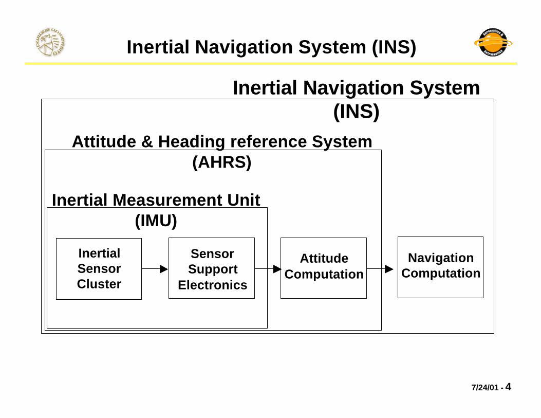
Inertial Navigation System (INS)
Inertial Sensor Cluster
Sensor Support
Electronics
Attitude Computation
Navigation Computation
Inertial Measurement Unit(IMU)
Attitude & Heading reference System(AHRS)
Inertial Navigation System(INS)

7/24/01 - 5
Major Error Sources
1. Inertial sensor errors
2. Initial misalignments
(significant but assumed to be 0 in the simulation)
3. Computational errors
e.g. - Higher order truncation
- Ignorance of high frequency motion
(assumed to be small relative to 1 & 2 in the simulation)

7/24/01 - 6
SIMULINK Diagram
Turbulence Input
Control Input R
Aircraft Model
INS Model
uIC(3)
deltaRic1
uIC(1)
deltaEic1
uIC(2)
deltaAic1
uIC(4)
bhpIC1
t
To Workspace8
ynav
To Workspace1
y
To Workspace
In1
In2
In3
In4
In5
In6
Out1
Strapdown INS
Mux
Mux1
Mux
Mux
Out1
Out2
Out3
Gust Subystem
Demux
Demux
Clock1
In1 Out1
Aircraft Subsystem Fbx/m
Fby /m
P
Q
Fbz/m
Aircraft Angular Rates
Aircraft Accelerations
True Aircraft Simulation
INS Simulation
7/24/01 - 7
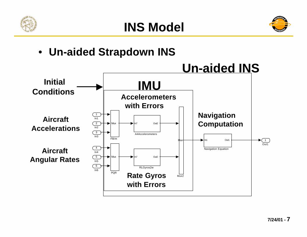
INS Model
Accelerometers with Errors
Rate Gyroswith Errors
1
Out1
In7 Out2
RLGyros2w
Mux
PQR
In1 Out1
Navigation Equation
Mux
Mux2
Mux
FB/m
In7 Out2
A4Accelerometers
6
In6
5
In5
4
In4
3
In3
2
In2
1
In1Aircraft Accelerations
Aircraft Angular Rates
• Un-aided Strapdown INS
IMUUn-aided INS
Navigation Computation
Initial Conditions

7/24/01 - 8
ii
i
jiij
i
ds with noise hiteGaussian wDparameter noise Random
)(1s BiasB)(1sparameter nality NonorthogoMM
)(1sfactor ScaleSrun)each in different run, a during(Constant constants Random
==•
==−==
•
Accelerometer Model With Errors
errortMeasuremenonaccelerati(actual)Input
onacceleratiMeasured~whereDDD
BBB
aaa
dadada
~
z
y
x
z
y
x
z
y
x
z
y
x
===
+
+
=
=
+=
daaa
da
daaa
zzyzx
yzyyx
xzxyx
SMMMSMMMS

7/24/01 - 9
Rate Gyro Model With Errors
errortMeasuremen:rateangular(actual)Input:
rateangularMeasured:~whereDDD
BBB
???
d?d?d?
~
z
y
x
z
y
x
z
y
x
z
y
x
d???
d?
d???
+
+
=
=
+=
zzyzx
yzyyx
xzxyx
SMMMSMMMS
1s with noise hiteGaussian wwparameterwalkRandomr
w)/r(Dparameter noise Random
)(1s BiasB)(1sparameter nality NonorthogoMM
)(1sfactor ScaleSrun)each in different run, a during(Constant constants Random
i
i
iii
i
jiij
i
===×=
•==−==
•
t
7/24/01 - 10
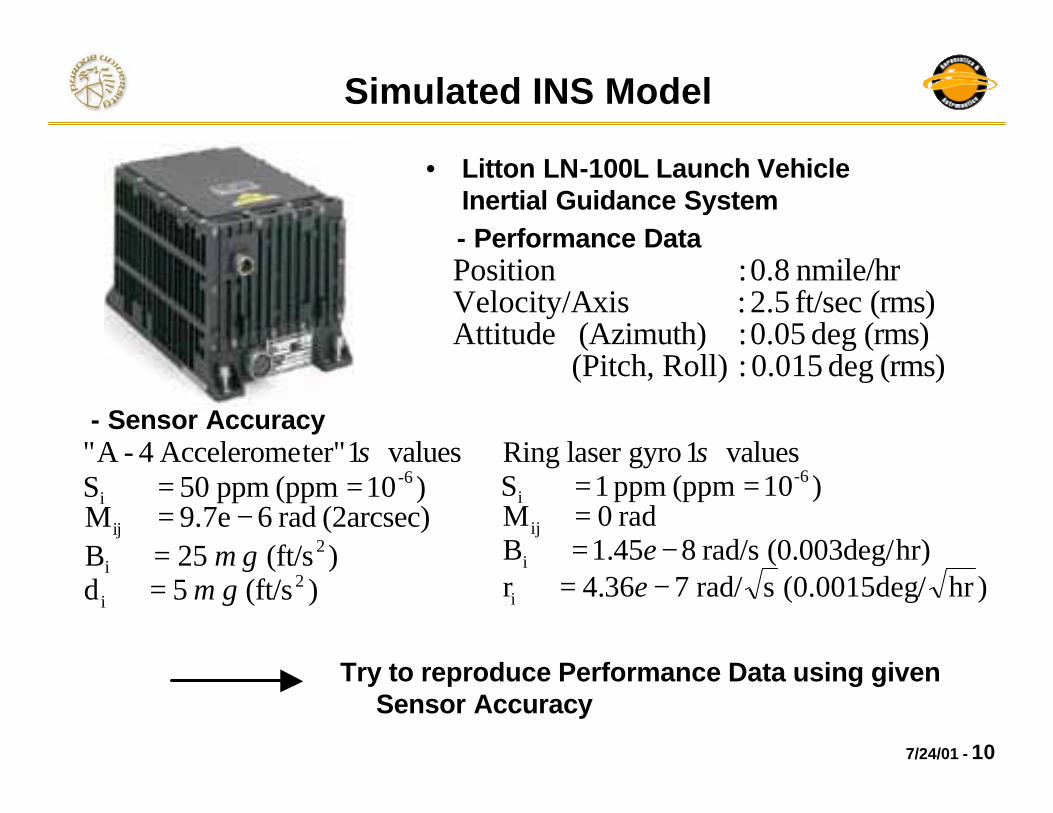
Simulated INS Model
(rms) deg 0.015 : Roll) (Pitch, (rms) deg 0.05 : (Azimuth) Attitude(rms) ft/sec 2.5 : xisVelocity/A
nmile/hr 0.8 : Position
)(ft/s5d)(ft/s25B
(2arcsec) rad 6e7.9M )10(ppm ppm50S
values1 ter"Accelerome 4-A"
2i
2i
ij
6-i
gg
µµ
σ
==
−===
• Litton LN-100L Launch Vehicle Inertial Guidance System
)hr/(0.0015deg srad/736.4rhr)(0.003deg/rad/s845.1B
rad 0M )10(ppm ppm1S
values1 gyrolaser Ring
i
i
ij
6-i
−=−=
===
ee
σ
Try to reproduce Performance Data using given Sensor Accuracy
- Performance Data
- Sensor Accuracy
7/24/01 - 11
Reference Frames
,iz
ix
iy
ex
ey
ez
O
λcλ
φψ
(North)
(East)
(Down)
nx
ny
nz
bx
by
bz
h
P
p
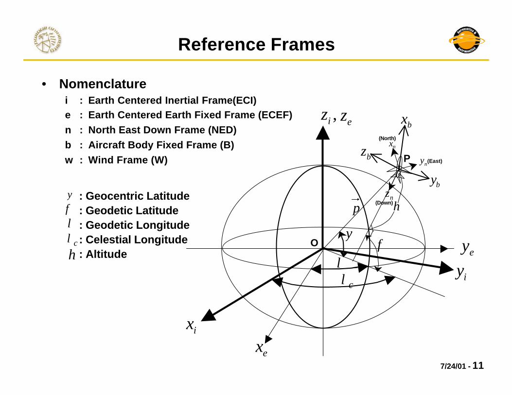
• Nomenclaturei : Earth Centered Inertial Frame(ECI)e : Earth Centered Earth Fixed Frame (ECEF)n : North East Down Frame (NED)b : Aircraft Body Fixed Frame (B)w : Wind Frame (W)
: Geocentric Latitude: Geodetic Latitude: Geodetic Longitude: Celestial Longitude: Altitude
ψφλ
cλh
7/24/01 - 12
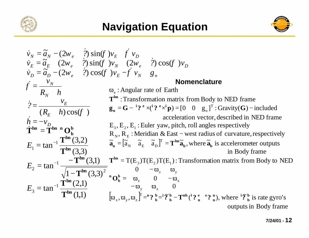
Navigation Equation
)1,1()1,2(
tan
)3,3(1
)1,3(tan
)3,3()2,3(
tan
)cos()(
)cos()2(~)cos()2()sin()2(~
)sin()2(~
13
2
12
11
bn
bn
bn
bn
bn
bn
bb
nbnbn
TT
T
TTT
OTT
−
−
−
=
−
−=
=
⋅=−=
+=
+=
+−+−=++++=
++−=
E
E
E
vhhRv
?
hRv
gvv?avv?v?av
vv?av
D
E
E
N
N
nNEeDD
DeNeEE
DEeNN
&&
&
&
&&&&&&
&&&
φ
φ
φφωφωφω
φφω
[ ]
[ ]frameBodyinoutputs
sgyro'rateis~where),(~,,
00
0NEDtoBodyfrommatrixtionTransforma:)E(T)E(T)E(T
frameBodyinoutputsteracceleromeis~where,~a~a~a~~
lyrespective curvature,ofradiuswest East&Meridian:R,Rlyrespectiveanglesrollpitch,yaw,Euler:E,E,E
frame NEDin described vector,onacceleratiincluded)Gravity(:]g00[)(
frameNEDtoBodyfrommatrixtionTransforma:EarthofrateAngular:
Tzyx
xy
xz
yz
123
TDEN
EN
123
Tn
e
bb
inn
een
inbbb
ibb
n
bb
n
bn
bbbn
n
ieiein
bn
???T??
O
T
aaTa
Gp??GgT
+−==ωωω
ωω−ω−ω
ωω−=
=
==−
−=××−=
ωNomenclature
7/24/01 - 13
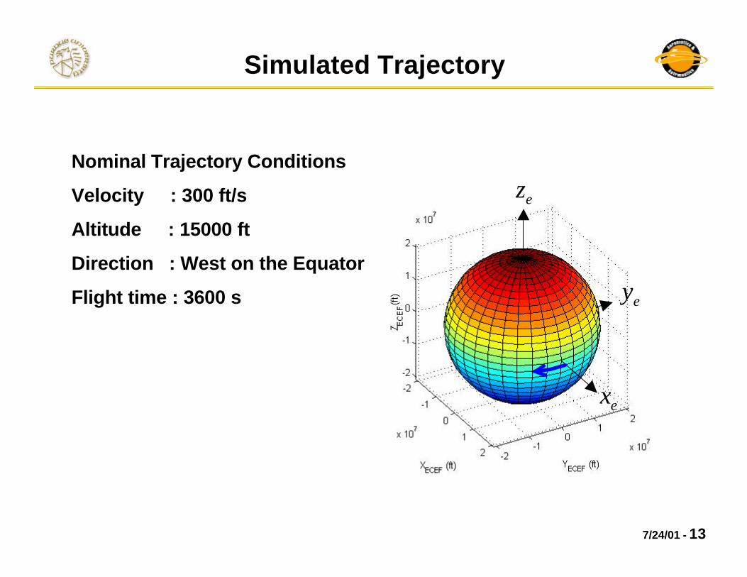
Simulated Trajectory
Nominal Trajectory Conditions
Velocity : 300 ft/s
Altitude : 15000 ft
Direction : West on the Equator
Flight time : 3600 s
ex
ey
ez

7/24/01 - 14
Numerical Simulation : Un-aided INS
0 500 1000 1500 2000 2500 3000 3500 4000-1
0
1
VN (ft/s)
Actual & Measured Velocities
0 500 1000 1500 2000 2500 3000 3500 4000-320
-310
-300
-290
VE (ft/s) Actual velocity
Measured velocity
0 500 1000 1500 2000 2500 3000 3500 4000-400
-200
0
200
VD (ft/s)
time (s)
0 500 1000 1500 2000 2500 3000 3500 4000-1
-0.5
0
0.5
δ VN (ft/s)
Velocity Measurement Errors
0 500 1000 1500 2000 2500 3000 3500 4000-20
-10
0
10
δ V
E (ft/s)
0 500 1000 1500 2000 2500 3000 3500 4000-300
-200
-100
0
δ V
D (ft/s)
time (s)
Velocities in NED frame (ft/s) )/( sftVVV actualmeasured −=δ
NV
EV
DV
NVδ
EVδ
DVδ
unbounded. isDVδ
unbounded.also isVEδ

7/24/01 - 15
Numerical Simulation : Un-aided INS
0 500 1000 1500 2000 2500 3000 3500 4000-5
0
5x 10
-5
φ (rad)
Actual & Measured Geodetic Positions
0 500 1000 1500 2000 2500 3000 3500 4000-0.06
-0.04
-0.02
0
λ (rad)
Actual geodetic position Measured geodetic position
0 500 1000 1500 2000 2500 3000 3500 40000
5
10
15x 10
4
h (ft)
time (s)
0 500 1000 1500 2000 2500 3000 3500 4000-10
-5
0
5x 10
-5
δ φ (rad)
Position Measurement Errors
0 500 1000 1500 2000 2500 3000 3500 4000-4
-2
0
2x 10
-4
δ λ (rad)
0 500 1000 1500 2000 2500 3000 3500 40000
1
2x 10
5
δ h (ft)
time (s)
Geodetic Positions
)(radφ
)(radλ
)( fth
)(radδφ
)(radδλ
)( fthδ
actualmeasured XXX −=δ
2t toproportionin increaseshδ Vertical channel error is
dominant

7/24/01 - 16
Error Equation
D
2E
E
E
EE
E
2N
NN
N
v-dhd
dhcos)hR(
vd
cos)hR(tanv
dvcos)hR(
1d
dh)hR(
vdv
)hR(1
d
~)2()2(~~
=φ+
−φφ+
φ+φ+
=λ
+−
+=φ
++×+−×+−×=−+×=−
&
&
&
&&
bbn
nnnn
eeb
in
nn
eeb
inn
bb
ibnnn
inn
i
adTdgv?d?dvd??eavd?dT?de?e
T
majorsemi
levelsea
TDEN
T
]hR
g2,0,0[
]v,v,v[anglesntmisalignme:],,[
where
δ−
=
δδδ=δγδβδα=
n
n
dg
dve
Attitude :
Velocity :
Position :
.iablesvarallerioratesdetandrapidlyincreacesh.errorsvelocityaffectsdirectly)size~(tersacceleromeofAccuracy
.errorsattitudeaffectsdirectly)size~(gyrosrateofAccuracy
δ⋅⋅⋅
bb
i
bb
i
?d?d
7/24/01 - 17
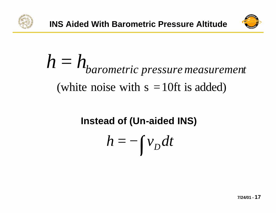
INS Aided With Barometric Pressure Altitude
tmeasuremenpressurebarometrichh =
Instead of (Un-aided INS)
∫−= dtvh D
added)is10ftswithnoise(white =

7/24/01 - 18
Numerical Simulation : INS Aided with Barometric Altitude
0 1000 2000 3000 4000 5000 6000-1
0
1
VN (ft/s)
Actual & Measured Velocities
0 1000 2000 3000 4000 5000 6000-305
-300
-295
VE (ft/s)
Actual velocity Measured velocity
0 1000 2000 3000 4000 5000 6000-20
-10
0
10
VD (ft/s)
time (s)
0 1000 2000 3000 4000 5000 6000-1
-0.5
0
0.5
δ VN (ft/s)
Velocity Measurement Errors
0 1000 2000 3000 4000 5000 6000-0.5
0
0.5
δ V
E (ft/s)
0 1000 2000 3000 4000 5000 6000-10
-5
0
δ VD (ft/s)
time (s)
Velocities in NED frame (ft/s)
NV
EV
DV
NVδ
EVδ
DVδ
)/( sftVVV actualmeasured −=δ
Horizontal velocity errors are bounded

7/24/01 - 19
Numerical Simulation : INS Aided with Barometric Altitude
0 1000 2000 3000 4000 5000 6000-5
0
5
10x 10
-5
φ (rad)
Actual & Measured Geodetic Positions
0 1000 2000 3000 4000 5000 6000-0.1
-0.05
0
λ (rad)
Actual geodetic position Measured geodetic position
0 1000 2000 3000 4000 5000 60001.48
1.49
1.5
1.51x 10
4
h (ft)
time (s)
0 1000 2000 3000 4000 5000 6000-10
-5
0
5x 10
-5
δ φ (rad)
Position Measurement Errors
0 1000 2000 3000 4000 5000 6000-2
0
2x 10
-5
δ λ (rad)
0 1000 2000 3000 4000 5000 6000-50
0
50
δ h (ft)
time (s)
Geodetic Positions actualmeasured XXX −=δ
)(radφ
)(radλ
)( fth
)(radδφ
)(radδλ
)( fthδ
Horizontal position errors are reduced
7/24/01 - 20
Status
• Simulation: Completed Components– Aircraft model– Ellipsoidal earth model– Turbulence– INS including errors
• Under Development– Kalman filter– Integration of external navigation aids
To do• Accuracy comparison changing
navigation aids / sensor performance
7/24/01 - 21
Conclusions
• Simulation of aircraft and INS is nearly completed.
• Error impact analysis and navigation technique comparison remain to be completed.
7/24/01 - 22
References
[1] Titterton, D. H. and Weston, J. L. (1997). “Strapdown Inertial Navigation Technology”. Peter Peregrinus Ltd, Herts, U. K.
[2] Rogers, R. M. (2000). “Applied Mathematics In Integrated Navigation Systems”. AIAA Education Series.
[3] Chatfield, A. B. (1997). “Fundamentals of High Accuracy Inertial Navigation”. Volume 174, Progress in Astronautics and Aeronautics. AIAA.
[4] Britting, K. R. (1971). “Inertial Navigation Systems Analysis”. Wiley Interscience.
[5] Brown, R. G. and Hwang, P. Y. C. (1985). “Introduction to Random Signals and Applied Kalman Filtering”. John Wiley & Sons.

7/24/01 - 23
Numerical Simulation : Un-aided INS
0 500 1000 1500 2000 2500 3000 3500 4000-5
0
5x 10
-3
E1 (rad)
Actual & Measured Euler Angles
0 500 1000 1500 2000 2500 3000 3500 4000-0.04
-0.03
-0.02
-0.01
E2 (rad)
0 500 1000 1500 2000 2500 3000 3500 4000-1.6
-1.55
-1.5
E3 (rad)
time (s)
Actual Euler angles Measured Euler angles
0 500 1000 1500 2000 2500 3000 3500 4000-4
-2
0
2x 10
-5
δ E1 (rad)
Euler Angle Measurement Errors
0 500 1000 1500 2000 2500 3000 3500 40000
2
4x 10
-4
δ E2 (rad)
0 500 1000 1500 2000 2500 3000 3500 4000-6
-4
-2
0x 10
-5
δ E3 (rad)
time (s)
Euler Angles (rad)
)(1
rollE
)(2
pitchE
)(3
yawE
)(1
rollEδ
)(2
pitchEδ
)(3
yawEδ
)(radEEE actualmeasured −=δ
7/24/01 - 24
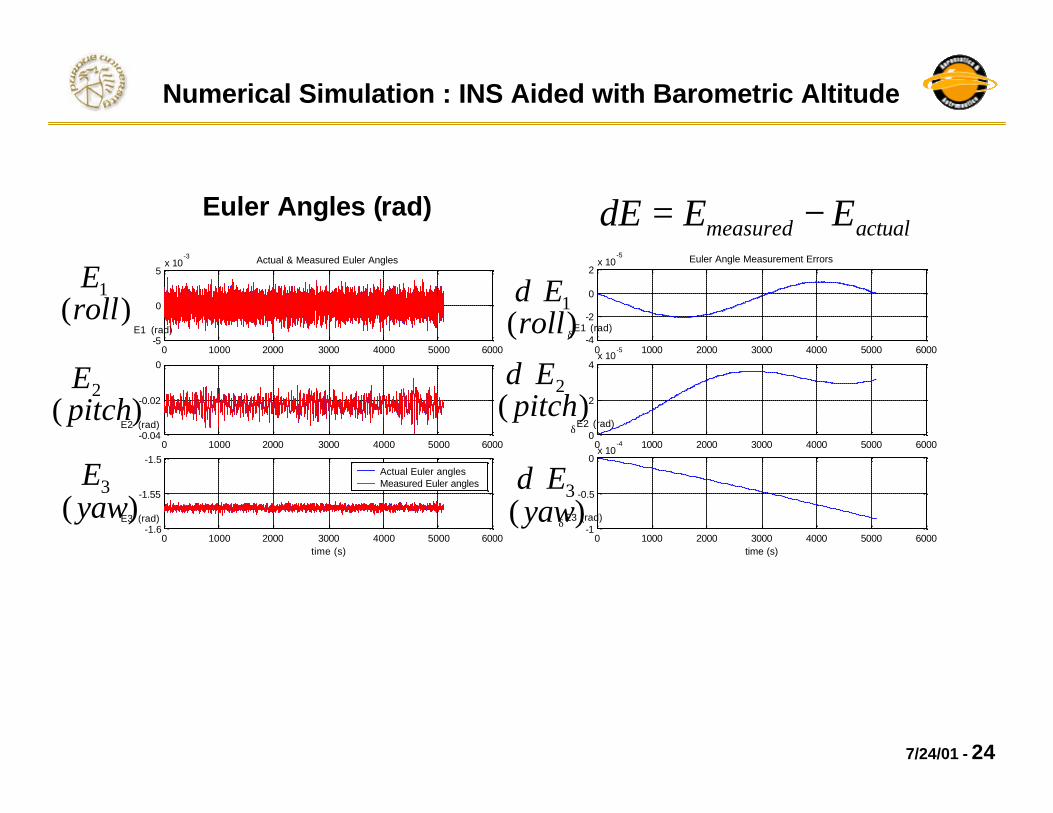
Numerical Simulation : INS Aided with Barometric Altitude
0 1000 2000 3000 4000 5000 6000-5
0
5x 10
-3
E1 (rad)
Actual & Measured Euler Angles
0 1000 2000 3000 4000 5000 6000-0.04
-0.02
0
E2 (rad)
0 1000 2000 3000 4000 5000 6000-1.6
-1.55
-1.5
E3 (rad)
time (s)
Actual Euler angles Measured Euler angles
0 1000 2000 3000 4000 5000 6000-4
-2
0
2x 10
-5
δ E1 (rad)
Euler Angle Measurement Errors
0 1000 2000 3000 4000 5000 60000
2
4x 10
-5
δ E2 (rad)
0 1000 2000 3000 4000 5000 6000-1
-0.5
0x 10
-4
δ E3 (rad)
time (s)
Euler Angles (rad)actualmeasured EEE −=δ
)(1
rollEδ
)(2
pitchEδ
)(3
yawEδ
)(1
rollE
)(2
pitchE
)(3
yawE


![Inertial Navigation Systems - Indico [Home]indico.ictp.it/event/a12180/session/23/contribution/14/material/0/... · Inertial Navigation Systems. Inertial Navigation Systems ... •](https://static.fdocuments.us/doc/165x107/5a94bdc87f8b9a451b8c1652/inertial-navigation-systems-indico-home-navigation-systems-inertial-navigation.jpg)