Aircraft NPP Impact Simulation Methodology
14
16 th International LS-DYNA ® Users Conference Simulation June 10-11, 2020 1 Aircraft NPP Impact Simulation Methodology Yu.V. Novozhilov 1 , A.N. Dmitriev 2 , D.S. Mikhaluk 2 , N.A Chernukha 3 , L.Yu. Feoktistova 3 , I.A. Volkodav 4 1 CADFEM CIS JSC, 2 CEPSA JSC, 3 ATOMPROECT JSC, 4 SEC DDC JSC, Saint-Petersburg, Russia Abstract The IAEA safety requirements imply that the design of nuclear power plants (NPP) considers both the potential technological disaster and acts of nature. One of the modern mandatory requirements of IAEA standard SRS 87 is to consider a possible massive commercial airplane crashing (APC) into or attacking NPP reinforced concrete (RC) structures. The basis for the methodology is well-validated RC structures modeling. LS-DYNA ® constitutive models have been tested by solving a set of verification problems. Selected problems set describes different loading conditions and scales: single finite element study, quasi- static loading, low-speed impact, deformable missile impact, RC wall APC load, shock wave load, perforation by a kinetic missile. The following model parameters are examined: mesh convergence, contact algorithms work, immersed reinforcement coupling, nonlinear stability. The second part of the paper presents a universal method of APC events direct modeling based on the finite element method in the Euler formulation. The relations allowing to identify geometrical, strength, and mass parameters of the airplane finite element model by the given load curve and impact spot are developed. The model of the aircraft obtained in this way allows the transfer of loads on complex- shaped civil structures or when considering the impact at an angle to the surface, with great fidelity. The last part describes the simulation results processing and analysis procedure. Criteria for determining the strength based on the analysis of displacement, strain, and damage of both concrete and reinforcements are proposed. Approach to the evaluation of penetration, perforation, and fracture speed behind the barrier estimation is developed. RC structures modeling technique LS-DYNA contains more than 12 models of materials, which allow describing concrete structure behavior [1]. In the present research the *MAT_CSCM(_CONCRETE)/*(MAT_159) concrete model is used [2]–[4]. The model is based on three invariant yield surface, can separately track tensile and compressive damage, adjust concrete strength and fracture energy according to the strain rate effect. All input parameters could be regenerated following the CEB-FIP Model Code [5] due to the “easy-input” procedure. This procedure provides initialization routines based on user input parameters of normal concrete strength ∈ [20; 58] MPa with emphasis on the midrange ∈ [28; 48] MPa[2]. Single element tests Several tests on uniaxial unconfined tension and compression of one finite element show that the declared initialization procedure gives material parameters with significant inaccuracies. The results obtained are also confirmed by a number of papers [6], [7]. So that new external initialization procedure is developed based on model initial data [2] and third-party research [6]. The procedure generates all input parameters based on user- inputted compressive strength and aggregate size data. Results for a single element test are shown in fig. 1 and 2.
Transcript of Aircraft NPP Impact Simulation Methodology

16th International LS-DYNA® Users Conference Simulation
June 10-11, 2020 1
Aircraft NPP Impact Simulation Methodology Yu.V. Novozhilov1, A.N. Dmitriev2, D.S. Mikhaluk2, N.A Chernukha3, L.Yu. Feoktistova3, I.A. Volkodav4
1CADFEM CIS JSC, 2CEPSA JSC, 3ATOMPROECT JSC, 4SEC DDC JSC, Saint-Petersburg, Russia
Abstract The IAEA safety requirements imply that the design of nuclear power plants (NPP) considers both the potential technological disaster and acts of nature. One of the modern mandatory requirements of IAEA standard SRS 87 is to consider a possible massive commercial airplane crashing (APC) into or attacking NPP reinforced concrete (RC) structures.
The basis for the methodology is well-validated RC structures modeling. LS-DYNA® constitutive models have been tested by solving a set of verification problems. Selected problems set describes different loading conditions and scales: single finite element study, quasi-static loading, low-speed impact, deformable missile impact, RC wall APC load, shock wave load, perforation by a kinetic missile. The following model parameters are examined: mesh convergence, contact algorithms work, immersed reinforcement coupling, nonlinear stability.
The second part of the paper presents a universal method of APC events direct modeling based on the finite element method in the Euler formulation. The relations allowing to identify geometrical, strength, and mass parameters of the airplane finite element model by the given load curve and impact spot are developed. The model of the aircraft obtained in this way allows the transfer of loads on complex-shaped civil structures or when considering the impact at an angle to the surface, with great fidelity.
The last part describes the simulation results processing and analysis procedure. Criteria for determining the strength based on the analysis of displacement, strain, and damage of both concrete and reinforcements are proposed. Approach to the evaluation of penetration, perforation, and fracture speed behind the barrier estimation is developed.
RC structures modeling technique LS-DYNA contains more than 12 models of materials, which allow describing concrete structure behavior [1]. In the present research the *MAT_CSCM(_CONCRETE)/*(MAT_159) concrete model is used [2]–[4]. The model is based on three invariant yield surface, can separately track tensile and compressive damage, adjust concrete strength and fracture energy according to the strain rate effect. All input parameters could be regenerated following the CEB-FIP Model Code [5] due to the “easy-input” procedure. This procedure provides initialization routines based on user input parameters of normal concrete strength 𝑓𝑓𝑐𝑐 ∈ [20; 58] MPa with emphasis on the midrange 𝑓𝑓𝑐𝑐 ∈[28; 48] MPa[2]. Single element tests Several tests on uniaxial unconfined tension and compression of one finite element show that the declared initialization procedure gives material parameters with significant inaccuracies. The results obtained are also confirmed by a number of papers [6], [7]. So that new external initialization procedure is developed based on model initial data [2] and third-party research [6]. The procedure generates all input parameters based on user-inputted compressive strength and aggregate size data. Results for a single element test are shown in fig. 1 and 2.

16th International LS-DYNA® Users Conference Simulation
June 10-11, 2020 2
Figure 1. Compressive concrete strength Figure 2. Tensile concrete strength
It could be seen that the internal initialization procedure significantly overestimates the compressive strength of the concrete and underestimate the tensile strength, which could reduce the overall simulation conservatism. Established an external initialization procedure reduces the error ten times. The newly developed initialization procedure verified on several well-known experimental cases: quasi-static cube sample loading [5], Fujikake low-speed impact on RC beam [8], Meppen-II-4 Slab Test [9], [10], RC wall APC load [11], Blind Blast Test[12]. The following model parameters are examined: mesh convergence, contact algorithms stability, immersed reinforcement coupling, nonlinear stability. The new initialization procedure is used for all these tests in a unified way – without additional parameter fitting after initialization. Fujikake Beam Low-Speed Impact Fujikake low-speed impact on the RC beam [8], [13] is used as an example of low-speed impact – we chose 3 test cases with maximum beam damage. The numerical model shows experiment correlation 7 – 3% for pick force reaction and 1.5 – 3% for maximal deflection. A quick overview of our results for the D1616 beam shown in fig. 3 – 5.
Figure 3. Beam reaction Figure 4. Beam deflection
a b Figure 5. Crack pattern:a – experiment, b – simulation redult, damage
*CONSTRAINDE_BEAM_IN_SOLID(_PENALTY) (CBIS) [14] algorithm is tested against node-to-node conformal beam-solid mesh merging in addition to the displacement and forces results. The test has shown excellent CBIS algorithm performance – the difference between conformal mesh and CBIS is neglected.
-10%
0%
10%
20%
30%
20 30 40 50 60
Stre
ngth
ow
eres
timat
ion
Concrete grade, MPa-10%
10%
30%
50%
70%
20 30 40 50 60
Stre
ngth
un
dere
stim
atio
n
Concrete grade, MPa
0
100
200
300
400
0 5 10 15 20 25 30
Cont
act f
orce
, kN
Time, ms
05
10152025
0 5 10 15 20 25 30
Def
lect
ion,
mm
Time, ms

16th International LS-DYNA® Users Conference Simulation
June 10-11, 2020 3
Meppen-II-4 Slab Test The impact of an aircraft engine on an RC panel is considered by a full-scale experiment on deformable projectile impact simulation – Meppen-II-4 Slab Test [9], [10]. A reinforced concrete panel is considered that is subjected to impact from a steel deformable projectile made in the form of a hollow cylinder. The projectile weighing 1016 kg has an initial velocity of 247.7 m/s. The reinforced concrete panel 700 mm thick has dimensions in plane 6000x6500 mm – see fig. 6. The reinforcement of the panel is made of two flat frames connected by U-shaped stirrups that act as a transverse reinforcement. The flat frame on the front side consists of 20 mm diameter rods, placed in 116 mm increments in two mutually perpendicular directions. The flat frame on the rear side consists of double rods with a diameter of 28 mm, placed in 232 mm increments in two mutually perpendicular directions; the distance between the axes of the paired rods is 58 mm. The U-shaped transverse stirrups, made of 20 mm diameter rods, are arranged in 232 mm increments. The distance from the axis of the outer reinforcement layer to the panel surface is 30 mm. The projectile is a hollow cylinder with a length of 6000 mm and a diameter of 600 mm, made up of pipes with walls of various thicknesses. With this crosssections dimension, the projectile cannot simply perforate concrete – it has to interact with all reinforcing rods, which significantly increases the complexity of the simulation.
Figure 6. Geometric
parameters end control points positions
b c Figure 7. FE model of the reinforced concrete panel: b –
concrete, c – reinforcing elements Impact simulation is done with three different mesh coarse (200 mm), medium (100 mm), and fine (50 mm). The state on the rear surface with comparison to crack pattern is shown in fig. 6. Mesh density increasing leads to damage zone localization and a more precise delineation of the crack pattern.
Тензодатчик
Сечение снаряда
Опорный анкер
Точки записи перемещений
Support anchorStrain gauge
Displacement record point
Projectile cross section

16th International LS-DYNA® Users Conference Simulation
June 10-11, 2020 4
a b c d
Figure 8. State on the rear surface of the: a – damage at coarse, b – medium, c – fine mesh, d – a sketch of the cracks resulting from the experiment
Several criteria perform a comparison of the simulation results with the experiment. The global impact response of the model is compared with data from a full-scale experiment. It is presented as a displacement-time relationship for given points of a reinforced concrete panel. A total of 8 displacement sensors are installed on the panel (Figure 6): four near the impact point (W3 - W6) and four at a distance (W1, W2, W7, W8). For each of the groups of points, the calculation results are averaged. A comparison of the calculation results with the experimental data is shown in fig. 7.
a b
Figure 9. Displacement at points on the rear surface of the panel for different FE mesh sizes: a - closer to the point of impact, b - further from the point of impact
As well as displacements, reaction forces are compared (without averaging). From literature sources, it is known the forces that occurred at the installation points of the K4 and K6 sensors (Figure 6), which are the anchor points of the reinforced concrete panel. A comparison of the experimental values of forces and calculation results for models with different FE meshes are shown in Figure 8. The calculation results show both good coincidence in amplitude and frequency of the arising force oscillations. The best coincidence is achieved for the model with the most detailed mesh.
-40-30-20-10
010
0 0.02 0.04 0.06 0.08 0.1
Dis
plac
emen
t, m
m
Time, s
-15
-10
-5
0
50.00 0.02 0.04 0.06 0.08 0.10
Dis
plac
emen
t, m
m
Time, s

16th International LS-DYNA® Users Conference Simulation
June 10-11, 2020 5
a b
Figure 10. Reaction forces occurring at the panel fixing points: a - sensor at the point K4, b - sensor at the point K6
Mesh Model Stability Study The stability of the model has been investigated when choosing the FE size less than the distance from the panel surface to the axis of the outer reinforcement layer. The considered model has an FE step equal to 30 mm. Feature of such a model is the presence of one unreinforced layer of elements (not connected with reinforcement elements by means of build-in reinforcement map *CONSTRAINED_BEAM_IN_SOLID) in the covering layer. Figure 9 shows the damage condition of the rear side of the panel at the end of impact (0.04 s) and at the last moment of calculation time (0.10 s). It can be seen that after removing the load, the structure shows a qualitatively good coincidence of the damage field with the sketch of cracks from the experiment (see fig. 6 a). However, after the load is removed, the damage continues to spread in the model due to the presence of a layer of fully unreinforced concrete elements on the model surface with the original mass. Under the influence of inertial forces, these elements are unphysically deforms, which leads to significant errors in the numerical scheme and instability of the resulting solution. The effect is most evident after removal of the load when the structure makes residual oscillations near the new equilibrium position. Based on the obtained results, it can be seen that the FE size of the concrete body has a limitation from below when solving local strength problems. It should not be less than the distance from the axis of the external longitudinal reinforcement rods to the corresponding surface of the concrete array. In other words, there should not be a layer of unreinforced concrete elements on the model surface.
a b c Figure 11. State on the rear surface of the panel: a – the moment of termination of impact, b –
the last moment of calculation time, c – the last moment of calculation time in isometric projection
-0.5
0
0.5
1
0.00 0.02 0.04 0.06 0.08 0.10
Forc
e, M
N
Time, s
-0.3
0
0.3
0.6
0.00 0.02 0.04 0.06 0.08 0.10
Forc
e, M
N
Time, s

16th International LS-DYNA® Users Conference Simulation
June 10-11, 2020 6
Blind Blast Test The test [15], [16] is chosen as an example of an RC slab under shock wave load and should check the blind calculation without the possibility of model presetting. In the current case, the results of the experiment are known in advance. The main purpose of this and all the tests described above is to ensure a new external initialization procedure for the CSCM model. The relationships underlying it are not subject to change for all cases. So even if we know the results of the experiment, we don't affect our concrete behavior.
a b
Figure 12. Concrete panel deflection for different load cases: a – large blast, b – smaller blast [16]
Figure 12 shows the deflection history of the slab center point for three different element size mesh: 30 mm, 10 mm and 5 mm. Figure 13 and 14 shows a crack pattern with a comparison to the experiment photo. In all cases, a good correlation with the experiment could be seen.
a b c d
Figure 13. Deformed shape and crack pattern for slab (rear side)): a – 30 mm elements, b – 10 mm elements, c – 5 mm elements, d – experimatal results [16]
0
50
100
150
0 20 40 60
Def
lect
ion,
mm
Time, ms
0
30
60
90
0 20 40 60
Def
lect
ion,
mm
Time, ms

16th International LS-DYNA® Users Conference Simulation
June 10-11, 2020 7
a b c d
Figure 14. Deformed shape and crack pattern for slab (isometric view): a – 30 mm elements, b – 10 mm elements, c – 5 mm elements, d – experimatal results [16]
Aircraft numerical model
The primary purpose of airplane impact NPP modeling is a civil structure performance testing under given extrema load. Traditionally, in such projects, the load case is set in the form of a reaction force curve calculated according to the Riera approach [17] and a history of the impact spot area change [11]. Riera's approach assumes that the aircraft target is a flat rigid wall that is fixed in all dimensions. NPP model has non-linear pliability and sophisticated shape. So that date from the Riera approach cannot be directly applied as a distributed pressure load in APC event simulation. NPP loading should be carried out through direct aircraft impact simulation. The model of the aircraft should reproduce the reaction curves and impact area specified in the project with maximum reliability. Basic aircraft input A large commercial aircraft is represented by Boeing 747-400 [17], [18], the velocity of the impact is assumed to be 150 m/s (see figures 11 – 12).
a
b
Figure 15. Load up on the impact of a Boeing 747-400 aircraft into a fixed barrier at an
initial impact speed of 150 m/s.
Figure 16. The impact area of a Boeing 747-400 aircraft into a rigid barrier:
a – fuselage, b – wings
0
100
200
300
400
0 0,2 0,4 0,6
Rea
ctiv
e fo
rce,
MN
Time, sec

16th International LS-DYNA® Users Conference Simulation
June 10-11, 2020 8
A universal methodology for modeling the loads imposed on building structures as a result of an aircraft impact is suggested [19], [20] — aircraft modeling based on a structured Eulerian formulation of the finite element method. The resulting shape of the simplified aircraft model is shown in fig. 12.
Figure 17. Boeing 747-400 [21] Figure 18. Aircraft SALE model shape
Model verification The aircraft SALE model verified by the rigidly fixed barrier normal impact. During the impact simulation, the reaction force curve is recorded with a frequency of 20 kHz and is not subjected to additional filtering or processing. It can be observed that the reaction curve almost entirely coincides with the initial load curve see fig. 13. It should be noted that the resulting curve is smooth - there are nearly no noise and spurious oscillations on the curve.
Figure 19. Comparison of Boeing 747-400 characteristic load and simplified SALE
aircraft model impact reaction on the rigidly fixed barrier
70.5 m49.7 m
8 m
0
100
200
300
400
0 0,1 0,2 0,3 0,4 0,5 0,6
Rea
ctiv
e fo
rce,
MN
Time, sec
Boeing 747-400 characteristic load
Simplified ALE aircraft model

16th International LS-DYNA® Users Conference Simulation
June 10-11, 2020 9
NPP model assembly
Generalized NPP containment outer shell is considered as an example of a civil structure subject to a heavy commercial aircraft impact. Mesh convergence for the impact task on RC has been shown above. The sufficient element mesh size for each case depends on the characteristic problem scale. There are no experimental studies on RC structures subject to heavy commercial aircraft impact by now, so sufficient mesh element size should be determined another way. Mesh sensitivity for large model Considered six different flat RC panels with varying parameters of reinforcement – see Table 1. Bending reinforcement for front and rear face with reinforcement spacing 200 mm presents in the models – shear reinforcement not simulated (fig. 13). The concrete grade is C50 and reinforcement steel A600[22]. All RC panel models fixed along the perimeter.
Figure 20. RC panel FE model: concrete and rebar (FE size 700 mm)
Table. 1. RC panels model list
No Panel dimensions (𝑤𝑤 × ℎ), m
Panel thickness, m
Reinforcement, mm
Mesh element size, mm
1 40 × 30
2.0 2D36 700, 500, 300, 200 2 1.8 2D36 700, 500, 300, 250, 200 3 1.5 2D32 700, 500, 300, 250, 200, 150 4
30 × 15 2.0 2D36 700, 500, 300, 200
5 1.8 2D36 700, 500, 300, 250, 200 6 1.5 2D32 700, 500, 300, 250, 200, 150
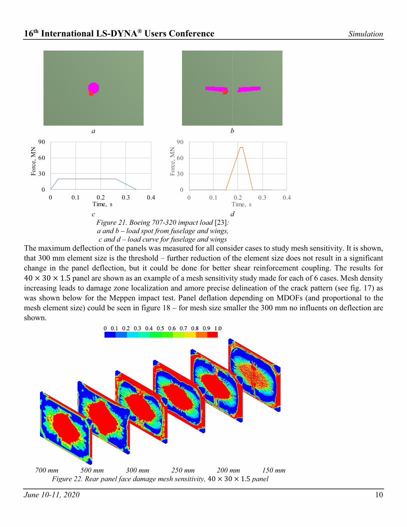
RC panels are loaded by distributed normal force from Boeing 707-320 impact load [23] fig. 17. A distributed pressure load is chosen for computation resource reduction purposes.
16th International LS-DYNA® Users Conference Simulation
June 10-11, 2020 10
a b
c d
Figure 21. Boeing 707-320 impact load [23]: a and b – load spot from fuselage and wings, c and d – load curve for fuselage and wings
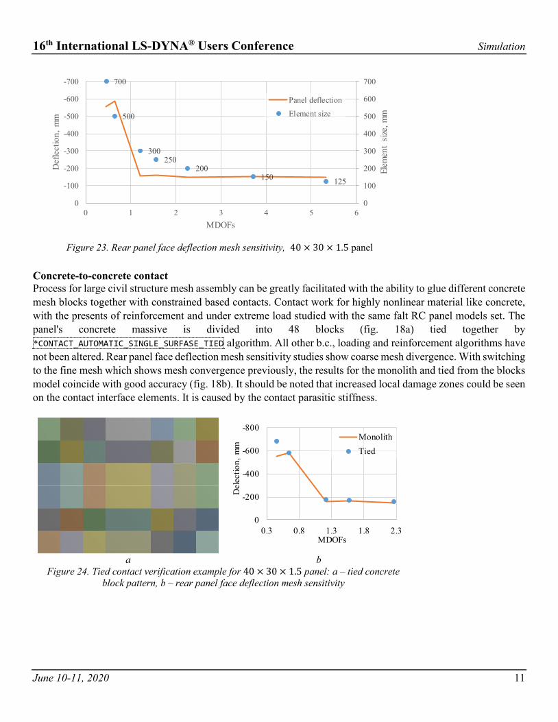
The maximum deflection of the panels was measured for all consider cases to study mesh sensitivity. It is shown, that 300 mm element size is the threshold – further reduction of the element size does not result in a significant change in the panel deflection, but it could be done for better shear reinforcement coupling. The results for 40 × 30 × 1.5 panel are shown as an example of a mesh sensitivity study made for each of 6 cases. Mesh density increasing leads to damage zone localization and amore precise delineation of the crack pattern (see fig. 17) as was shown below for the Meppen impact test. Panel deflation depending on MDOFs (and proportional to the mesh element size) could be seen in figure 18 – for mesh size smaller the 300 mm no influents on deflection are shown.
700 mm 500 mm 300 mm 250 mm 200 mm 150 mm
Figure 22. Rear panel face damage mesh sensitivity, 40 × 30 × 1.5 panel
0
30
60
90
0 0.1 0.2 0.3 0.4
Forc
e, M
N
Time, s
0
30
60
90
0 0.1 0.2 0.3 0.4
Forc
e, M
N
Time, s
16th International LS-DYNA® Users Conference Simulation
June 10-11, 2020 11
Figure 23. Rear panel face deflection mesh sensitivity, 40 × 30 × 1.5 panel
Concrete-to-concrete contact Process for large civil structure mesh assembly can be greatly facilitated with the ability to glue different concrete mesh blocks together with constrained based contacts. Contact work for highly nonlinear material like concrete, with the presents of reinforcement and under extreme load studied with the same falt RC panel models set. The panel's concrete massive is divided into 48 blocks (fig. 18a) tied together by *CONTACT_AUTOMATIC_SINGLE_SURFASE_TIED algorithm. All other b.c., loading and reinforcement algorithms have not been altered. Rear panel face deflection mesh sensitivity studies show coarse mesh divergence. With switching to the fine mesh which shows mesh convergence previously, the results for the monolith and tied from the blocks model coincide with good accuracy (fig. 18b). It should be noted that increased local damage zones could be seen on the contact interface elements. It is caused by the contact parasitic stiffness.
a b Figure 24. Tied contact verification example for 40 × 30 × 1.5 panel: a – tied concrete
block pattern, b – rear panel face deflection mesh sensitivity
700
500
300250
200150 125
0
100
200
300
400
500
600
700-700
-600
-500
-400
-300
-200
-100
00 1 2 3 4 5 6
Elem
ent
size
, mm
Def
lect
ion,
mm
MDOFs
Panel deflection
Element size
-800
-600
-400
-200
00.3 0.8 1.3 1.8 2.3
Del
ectio
n, m
m
MDOFs
MonolithTied

16th International LS-DYNA® Users Conference Simulation
June 10-11, 2020 12
Aircraft NPP impact simulation methodology conclusion Thus, the team of authors carried out complete aircraft NPP impact simulation methodology. The concrete model is chosen and recalibrated for better EC2 alignment. The model verified on a multitude of different scales and different strain rate experiments. Coupling algorithms such as concrete-to-concrete tied contact and concrete to immersed reinforcement tested. The procedure of aircraft model reconstruction from reaction force curve and impact zone shape is developed. All these tests performed with respect to mesh sensitivity studies. With this methodology, it is possible to create highly detailed aircraft NPP impact event numerical models, as shown hereinafter
Table. 2. Generalized NPP containment model parameters
Model parameter Value, millions Concrete Rebar bending Shear bending
Element number 3.8 2.3 5.9 Node number 4.3 2.3 6.5 DOF number 12.8 14.0 38.9
Such a model of NPP structures, incuding 200 mm size solids for concrete and all shear and bending reinforcement could be run on 128 Gb RAM SMP server on 64 cores for about 200 hours. Construction prestresses effects from gravity and pretension trusses could be also included in the simulation. The prestress effect procedure is developed and tested also, and it could add about 50 hours CPU time. Based on the simulation results, it is possible to make a judgment on the construction state. The damaged concrete damage zones should examed carefully. Concrete softening and cracking, not necessarily, leads to penetration, scabbing, or perforation. Concrete displacement and shear strain [24] could give an idea of forming completely through the wall cracking zones. Rebars state should also be taken into account – even crushed concrete can retain its load-bearing capacity inside reinforcement bars cage. So that, a significant zone of all layer rebars failure should be tracked for construction perforation check. It could be seen that for such a complex composite material as RC constituent failure criterium should be used: construction displacement, concrete damage, and strain, rebars failure.

16th International LS-DYNA® Users Conference Simulation
June 10-11, 2020 13
0.15 s 0.35 s
0.50 s 0.70 s
Figure 25. Boeing 747-400 impact to generalized NPP containment – process key points

16th International LS-DYNA® Users Conference Simulation
June 10-11, 2020 14
References
[1] J. O. Hallquist, LS-DYNA Theory Manual. Livermore: Livermore Software Technology Corporation, 2016. [2] Y. D. Murray, «Users Manual for LS-DYNA Concrete Material Model 159», Fed. Highw. Adm., May, p. 77, 2007. [3] Y. D. Murray, A. Abu-Odeh, and R. Bligh, «Evaluation of LS-DYNA Concrete Material Model 159. Report no. FHWA-HRT-
05-063», 2007. [4] Y. D. Murray, «Theory and Evaluation of Concrete Material Model 159», 8th Int. LS-DYNA Users Conf., p. 25–36, 2004. [5] CEB-FIP, CEB-FIP model code 1990. London: Thomas Telford Services Ltd, 1993. [6] H. Jiang and J. Zhao, «Calibration of the continuous surface cap model for concrete», Finite Elem. Anal. Des., vol. 97, p. 1–
19, 2015. [7] B. J. Winkelbauer, «Phase I Evaluation of Selected Concrete Material Models in LS-DYNA», 2015. [8] K. Fujikake, B. Li, and S. Soeun, «Impact Response of Reinforced Concrete Beam and Its Analytical Evaluation», vol. 135,
issue August 2009, p. 938–950, 2010. [9] C. J. Heckötter Sievers Berichtszeitraum, «GRS-A-3677 Validierung von Analyse-methoden zur Simulation von
Aufprallversuchen im In-und Ausland Validation of Analysis Methods to Simulate National and International Impact Experiments», 2012.
[10] W. Jonas, R. Meschkat, H. Riech, and E. Rüdiger, «Experimental Investigations to Determine the Kinetic Ultimate Bearing Capacity of Reinforced Concrete Slabs Subject to Deformable Missiles», 1979.
[11] IAEA, Safety Reports Series No. 87: Safety Aspects of Nuclear Power Plants in Human Induced External Events: General Considerations. 2017.
[12] Y. Wu, J. E. Crawford, S. Lan, and J. M. Magallanes, «Validation Studies for Concrete Constitutive Models with Blast Test Data», 13th Int. LS-DYNA Users Conf., DOI: https://doi.org/10.32326/1814-9146-2020-82-1-5-15
[13] S. Gertsik and Y. Novozhilov, «Numerical simulation of a massive impactor falling onto a reinforced concrete beam», Strength and plastisity problems, vol. 82, issue. 1, p. 5–15, 2020. DOI: https://doi.org/10.32326/1814-9146-2020-82-1-5-15
[14] H. Chen, «An Introduction to *CONSTRAINED_BEAM_IN_SOLID», FEA Inf. Eng. J., vol. 6, issue Q1, p. 14–18, 2017. [15] L. Schwer, «BLIND BLAST SIMULATION». [16] «Blast Blind Simulation Contest». [Online]. http://sce2.umkc.edu/blast-prediction-contest/home.html. [10-jul-2019]. [17] J. D. Riera, «On the Stress Analysis of Structures Subjected To Aircraft Impact Forces», Nucl. Eng. Des. North-holl. Publ.
Comp, vol. 8, p. 415–426, 1968. [18] A.N. Birbraer and A.Yu. Roleder, Exteram load on civil structures. Saint-Petersburg, 2009. [19] A. Kultsep, M. Souli, and I. Volkodav, «Load on structures due to large airplane impact», 2013. [20] Y. V. Novozhilov, D. S. Mikhaluk, and L. Y. Feoktistova, «Calculation of aircraft impact load on the NPP nuclear island
buildings», Comput. Contin. Mech., vol. 11, isue. 3, p. 288–301, 2018. DOI: http://dx.doi.org/10.7242/1999-6691/2018.11.3.22
[21] «Boeing 747-400 Freighter». [Online]. Link: https://testpilot.ru/usa/boeing/747/400/f/. [22-nov-2018]. [22] «Eurocode 2 : Design of concrete structures», Design, vol. 3, July, p. 23–28, 2003. [23] A. E. Stephenson, «Full-scale tornado-missile impact tests. Final report». 1977. [24] Nuclear Energy Institute, «Methodology for Performing Aircraft Impact Assessments for New Plant Designs (NEI 07-13
Revision 8P)», 2011.