Air Slide Table the case slide table is stopped at intermediate positions by the external stopper...
24
RoHS Linear guide table provides long stroke. Table rigidity is constant throughout entire stroke. Stroke adjuster Piping, Wiring • Piping is possible from 2 directions. • Can pipe and wire switches from the same surface. • Auto switch can be attached to either side of body. Dual piston rod • Slim design provides 2 times the force of standard cylinder. MXW8: ø8 x 2 MXW12: ø12 x 2 MXW16: ø16 x 2 Body mounting • 2 mounting types (Body tapped, Through-hole) are available. Thread for body mounting Body tapped Body through-hole Machining of positioning hole MXW20: ø20 x 2 MXW25: ø25 x 2 Table for mounting of workpiece Long stroke (Max. 300 mm) Linear guide provides long stroke, and it obtains smooth operation without vibration. 25 50 75 100 125 150 175 200 225 250 275 300 Stroke (mm) MXW8 MXW12 MXW16 MXW20 MXW25 Axial piping Shock absorber Lateral piping/wiring MXW Series Air Slide Table ø8, ø12, ø16, ø20, ø25 281 MXH MXS MXQ MXQ MXF MXJ MXP MXY MTS D- -X MXW
Transcript of Air Slide Table the case slide table is stopped at intermediate positions by the external stopper...
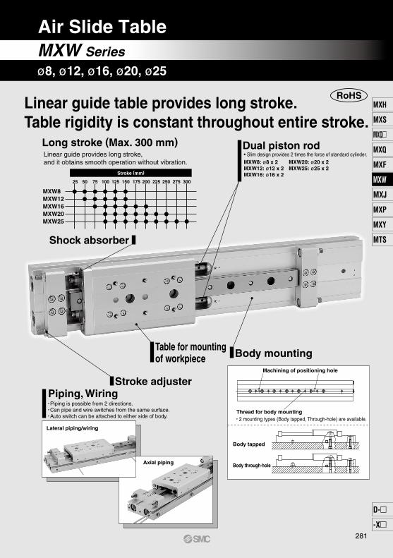
RoHSLinear guide table provides long stroke.Table rigidity is constant throughout entire stroke.
Stroke adjusterPiping, Wiring• Piping is possible from 2 directions.• Can pipe and wire switches from the same surface.• Auto switch can be attached to either side of body.
Dual piston rod• Slim design provides 2 times the force of standard cylinder.MXW8: ø8 x 2MXW12: ø12 x 2MXW16: ø16 x 2
Body mounting
• 2 mounting types (Body tapped, Through-hole) are available.Thread for body mounting
Body tapped
Body through-hole
Machining of positioning hole
MXW20: ø20 x 2MXW25: ø25 x 2
Table for mounting of workpiece
Long stroke (Max. 300 mm)Linear guide provides long stroke, and it obtains smooth operation without vibration.
25 50 75 100 125 150 175 200 225 250 275 300
Stroke (mm)
MXW8MXW12MXW16MXW20MXW25
Axial piping
Shock absorber
Lateral piping/wiring
MXW Series
Air Slide Table
ø8, ø12, ø16, ø20, ø25
281
MXH
MXS
MXQ
MXQ
MXF
MXW
MXJ
MXP
MXY
MTS
D-
-X
MXW

Load WeightMaximum Load Mass
Model
MXW8
MXW12
MXW16
MXW20
MXW25
W
1.8
4
7
11
17
(kg)
Model
MXW8
MXW12
MXW16
MXW20
MXW25
Pitch moment
Mp/Mep
5
10
20
40
110
Yaw moment
My/Mey
5
10
20
40
110
Roll moment
Mr
3
6
12
25
65
Pitch moment
MXW8 MXW12MXW16MXW20MXW25
3948587597
Yaw moment Roll moment
MXW8 MXW12MXW16MXW20MXW25
2329374963
MXW8 MXW12MXW16MXW20MXW25
1010142028
My
W
WW
L2 B1
Mp/Mep (Pitch moment)My/Mey (Yaw moment) Mr (Roll moment)
Moment
Moment generated by the workpiece weight even when the cylinder is stopped
W
Graph (1)
Graph (3)Graph (2)
(N·m)
Mr
L3 C2
W
MXW8 MXW12MXW16MXW20MXW25
1010142028
MXW8 MXW12MXW16MXW20MXW25
2329374963
Mp
L1 A1
WL1 A2
W
Mp
Mr
L3 C1
W
Static Moment
MXW8 MXW12MXW16MXW20MXW25
3948587597
20
15
10
54
3
2
1
7
50 100 200 300 500
1.5
50 100 200 300 500
10
50
20
3040
70
1.550 100 200 300 500
10
50
20
3040
70100
700
120
12
25
17
15
15
2.5
6
12
1.2
1.7
2.5
Piston speed (mm/s)
Max
imum
load
mas
s (k
g)
Average operating speed (mm/s)
Max
imum
mom
ent (
N·m
)
3
2
45
7
Average operating speed (mm/s)
Max
imum
mom
ent (
N·m
)
7543
2
W
My
W
L2 B2
MXW25MXW20MXW16MXW12
MXW8
MXW25
MXW20
MXW16
MXW12
MXW8
MXW25
MXW20MXW16MXW12MXW8
Operate loads within the range of the operating limits.Select the model from the maximum allowable load and allowable moment. For details, refer to the following selection procedures. When actuator is used outside of operating limit, eccentric loads on the guide in excess, will cause vibration on guide, inaccuracy and shorten its life.
Selection If intermediate stops by external stopper are done, avoid ejection.If ejection occurs, it may cause damage. In the case slide table is stopped at intermediate positions by the external stopper then forwarded to the front, after slide table is returned to the back for just a moment to retract the stopper, supply pressure to the opposite port to operate slide table.Do not use it in such a way that excessive external force or impact force could work on it.This could result in damage.
Caution
Maximum allowable load and allowable moment will vary depending on workpiece mounting methods, mounting orientation and operating speed.In making a determination of usability, the load mass and moment should be within the operating range of the graph with respect to operating conditions and the total (Σn) of the load factors (n) for load mass and moment should not exceed 1.
Σn = Load (W)
Maximum load mass (Wmax) +
Static moment (M)Allowable static moment (Mmax)
+ Dynamic moment (Me)
Allowable dynamic moment (Memax)< 1
Wmax, Mmax and Memax values are according to graph (1), (2) and (3) below.
Note) No need to consider this load factor in the case of using perpendicularly in a vertical position.
(Static moment/Dynamic moment) Allowable Moment
A1: Moment center position distance compensation amount (mm)
Mp = W x 9.8 (L1 + A) My = W x 9.8 (L2 + B)
A2: Moment center position distance compensation amount (mm)
B2: Moment center position distance compensation amount (mm)
B1: Moment center position distance compensation amount (mm)
Mr = W x 9.8 (L3 + C)
C1: Moment center position distance compensation amount (mm)
C2: Moment center position distance compensation amount (mm)
MXW Series
Model Selection
282A
W
L3C
Mr
BL2
W
L3+C
Mey
We W
L2+
B
Mep
We
L3+
C
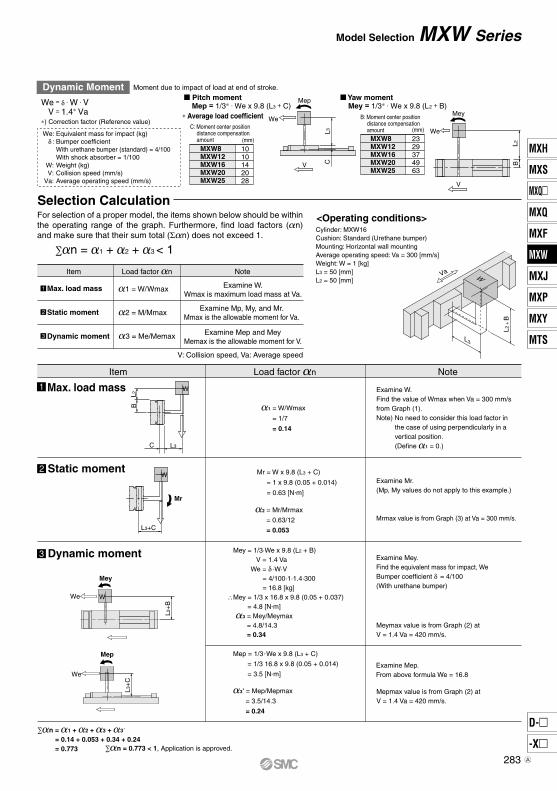
Selection Calculation
Item Load factor n Note
<Operating conditions>
Item Load factor n Note
Va
L3
W
L2 +
B
Pitch moment
MXW8 MXW12MXW16MXW20MXW25
1010142028
MXW8 MXW12MXW16MXW20MXW25
2329374963
We: Equivalent mass for impact (kg) δ : Bumper coefficient With urethane bumper (standard) = 4/100 With shock absorber = 1/100 W: Weight (kg) V: Collision speed (mm/s) Va: Average operating speed (mm/s)
Moment due to impact of load at end of stroke.
We = δ · W · V V = 1.4∗ Va∗) Correction factor (Reference value)
Mey
L2B
Mep
CL3
We
V
V
We
Dynamic Moment
Mep = 1/3∗ · We x 9.8 (L3 + C) Yaw moment
Mey = 1/3∗ · We x 9.8 (L2 + B)∗ Average load coefficient
C: Moment center position distance compensation amount
B: Moment center position distance compensation amount
(mm)
(mm)
Cylinder: MXW16Cushion: Standard (Urethane bumper)Mounting: Horizontal wall mountingAverage operating speed: Va = 300 [mm/s]Weight: W = 1 [kg] L3 = 50 [mm]L2 = 50 [mm]
1 = W/Wmax
2 = M/Mmax
3 = Me/Memax
Max. load mass
Static moment
Dynamic moment
Examine W.Wmax is maximum load mass at Va.
Examine Mp, My, and Mr.Mmax is the allowable moment for Va.
Examine Mep and MeyMemax is the allowable moment for V.
V: Collision speed, Va: Average speed
Max. load mass
Static moment
Dynamic moment
1 = W/Wmax
= 1/7
= 0.14
Mr = W x 9.8 (L3 + C)
= 1 x 9.8 (0.05 + 0.014)
= 0.63 [N m]
2 = Mr/Mrmax
= 0.63/12
= 0.053
Mey = 1/3·We x 9.8 (L2 + B)V = 1.4 Va
We = δ ·W·V= 4/100·1·1.4·300= 16.8 [kg]
∴Mey = 1/3 x 16.8 x 9.8 (0.05 + 0.037)= 4.8 [N m]
3 = Mey/Meymax= 4.8/14.3= 0.34
Mep = 1/3 We x 9.8 (L3 + C)
= 1/3 16.8 x 9.8 (0.05 + 0.014)
= 3.5 [N m]
3' = Mep/Mepmax
= 3.5/14.3
= 0.24
Examine W.Find the value of Wmax when Va = 300 mm/sfrom Graph (1).Note) No need to consider this load factor in
the case of using perpendicularly in a vertical position. (Define 1 = 0.)
Examine Mr.(Mp, My values do not apply to this example.)
Mrmax value is from Graph (3) at Va = 300 mm/s.
Examine Mey.Find the equivalent mass for impact, We Bumper coefficient δ = 4/100(With urethane bumper)
Meymax value is from Graph (2) at V = 1.4 Va = 420 mm/s.
Examine Mep.From above formula We = 16.8
Mepmax value is from Graph (2) at V = 1.4 Va = 420 mm/s.
MXW SeriesModel Selection
For selection of a proper model, the items shown below should be within the operating range of the graph. Furthermore, find load factors (n) and make sure that their sum total (Σn) does not exceed 1.
283
MXH
MXS
MXQ
MXQ
MXF
MXW
MXJ
MXP
MXY
MTS
D-
-X
MXW
A

Applicable Auto Switches/Refer to pages 1119 to 1245 for the detailed specifications of auto switches.
M9NVM9PVM9BV
M9NWVM9PWVM9BWV
M9NAV∗1
M9PAV∗1
M9BAV∗1
M9NM9PM9B
M9NWM9PWM9BW
M9NA∗1
M9PA∗1
M9BA∗1
Special function
24 V
3-wire (NPN) 3-wire (PNP)
2-wire3-wire (NPN)3-wire (PNP)
2-wire3-wire (NPN)3-wire (PNP)
2-wire
Electricalentry
Load voltageWiring
(Output)Pre-wiredconnector
Applicable loadDC AC
Auto switch model Lead wire length (m)
Perpendicular In-line0.5(Nil)
5(Z)
Grommet —
1(M)
Relay,PLC
—
Diagnostic indication (2-color indicator)
Water resistant(2-color indicator)
5 V,12 V
12 V
5 V,12 V
12 V
5 V,12 V
12 V
3(L)
A96V
A93V∗2
A90V
A96
A93A90
3-wire (Equiv. to NPN) —
24 VGrommet
2-wire
—
100 V100 V or less
—
Relay,PLC
—5 V
12 V
RoHS
∗1 Water resistant type auto switches can be mounted on the above models, but in such case SMC cannot guarantee water resistance.∗2 1 m type lead wire is only applicable to D-A93.
∗ For the applicable auto switch model, refer to the table below.ø8ø12ø16ø20ø25
25, 50, 75, 100, 125, 15050, 75, 100, 125, 150 75, 100, 125, 150, 175, 200100, 125, 150, 175, 200, 225, 250100, 125, 150, 175, 200, 225, 250, 275, 300
Bore size (Stroke (mm))
B
S n
Option
Auto switchWithout auto switch (Built-in magnet)
MXW 16 100 B M9BWMade to OrderRefer to page 285 for details.
M threadRc
NPTG
ø8 to ø16
ø20, ø25
Port thread type
TNTF
Nil
Nil Standard (with urethane bumper)With shock absorbers 2 pcs.
Number of auto switches
Nil
Nil
2 pcs.1 pc.
“n” pcs.
IC circuit
IC circuit
IC circuit
IC circuit
—
—
—
—IC circuit
Air Slide Table
MXW SeriesHow to Order
Type
Ree
dau
to s
witc
hS
olid
sta
teau
to s
wit
ch
Indica
tor lig
ht
Yes
None
Yes
∗ Solid state auto switches marked with “” are produced upon receipt of order.∗ Lead wire length symbols: 0.5 m·········· Nil1 m·········· M3 m·········· L5 m·········· Z
(Example) M9NW(Example) M9NWM(Example) M9NWL(Example) M9NWZ
∗ Since there are other applicable auto switches than listed, refer to page 301 for details.∗ For details about auto switches with pre-wired connector, refer to pages 1192 and 1193.∗ Auto switches are shipped together (not assembled).
284
Standard Stroke (mm)/Weight (g)
125
880
1270
2150
4640
9620
100
790
1140
1970
4440
9300
75
700
1010
1850—
—
50
610
930—
—
—
Standard stroke (mm) Additional weight of optionModel
MXW8
MXW12
MXW16
MXW20
MXW25
150
980
1400
2350
5000
9970
175—
—
2540
5360
10500
200—
—
2740
5710
11100
250—
—
—
6430
12200
225—
—
—
6070
11700
25
550—
—
—
—
275—
—
—
—
12800
300—
—
—
—
13400
Shock absorber
15
15
20
65
140
Bore size (mm)
Piping port size
Fluid
Action
Operating pressure
Proof pressure
Ambient and fluid temperature
Cushion
Lubrication
Stroke length tolerance
Stroke adjustment range
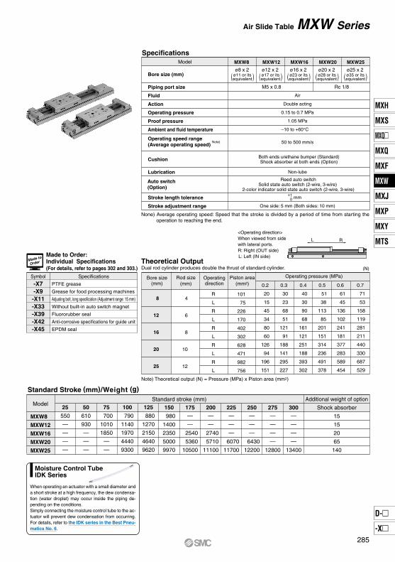
Specifications
Rc 1/8M5 x 0.8
8
12
16
20
25
4
6
8
10
12
R
L
R
L
R
L
R
L
R
L
101
75
226
170
402
302
628
471
982
756
0.2
20
15
45
34
80
60
126
94
196
151
0.3
30
23
68
51
121
91
188
141
295
227
0.4
40
30
90
68
161
121
251
188
393
302
0.5
51
38
113
85
201
151
314
236
491
378
0.6
61
45
136
102
241
181
377
283
589
454
0.7
71
53
158
119
281
211
440
330
687
529
MXW8 MXW16 MXW20
L R
MXW12 MXW25
Air
Double acting
0.15 to 0.7 MPa
1.05 MPa
–10 to +60°C
50 to 500 mm/s
Non-lube
mm
One side: 5 mm (Both sides: 10 mm)
+10
Symbol Specifications
PTFE grease
Grease for food processing machines
Adjusting bolt, long specification (Adjustment range: 15 mm)
Without built-in auto switch magnet
Fluororubber seal
Anti-corrosive specifications for guide unit
EPDM seal
-X7-X9-X11-X33-X39-X42-X45
Model
ø8 x 2ø11 or itsequivalent( )
ø12 x 2ø17 or itsequivalent
ø16 x 2ø23 or itsequivalent
ø20 x 2ø28 or itsequivalent
ø25 x 2ø35 or itsequivalent( )( )( )( )
<Operating direction>When viewed from sidewith lateral ports.R: Right (OUT side)L: Left (IN side)Made to Order:
Individual Specifications(For details, refer to pages 302 and 303.)
Bore size(mm)
Rod size(mm)
Operatingdirection
Operating pressure (MPa)Piston area(mm2)
Theoretical OutputDual rod cylinder produces double the thrust of standard cylinder. (N)
Note) Theoretical output (N) = Pressure (MPa) x Piston area (mm2)
MXW SeriesAir Slide Table
Made to
Order
None) Average operating speed: Speed that the stroke is divided by a period of time from starting the operation to reaching the end.
Operating speed range(Average operating speed)
Note)
Auto switch(Option)
Both ends urethane bumper (Standard)Shock absorber at both ends (Option)
Reed auto switchSolid state auto switch (2-wire, 3-wire)
2-color indicator solid state auto switch (2-wire, 3-wire)
When operating an actuator with a small diameter and a short stroke at a high frequency, the dew condensa-tion (water droplet) may occur inside the piping de-pending on the conditions.Simply connecting the moisture control tube to the ac-tuator will prevent dew condensation from occurring. For details, refer to the IDK series in the Best Pneu-matics No. 6.
Moisture Control TubeIDK Series
285
MXH
MXS
MXQ
MXQ
MXF
MXW
MXJ
MXP
MXY
MTS
D-
-X
MXW

A F
F A
L
L = 200 mm
L A
F
L L = 200 mm
L = 200 mm
500100 200 300 400 600
0.01
0.02
0.03
MXW25MXW20
400
MXW25MXW20
300200100
0.10
0.04
0.08
0.02
0.06
100
0.01
0.02
0.03
MXW12MXW8 MXW16
755025 100
0.01
0.02
0.03
MXW12MXW8 MXW16
755025
MXW12MXW8 MXW16
0.10
0.04
0.08
0.02
0.06
20 40 60
500100 200 300 400 600
0.01
0.02
0.03
MXW25MXW20
MXW8, MXW12, MXW16
MXW20, MXW25
MXW8, MXW12, MXW16
MXW20, MXW25
MXW8, MXW12, MXW16
MXW20, MXW25
Load (N)
Tab
le d
ispl
acem
ent a
mou
nt (
mm
)
Load (N)
Tab
le d
ispl
acem
ent a
mou
nt (
mm
)
Load (N)
Tab
le d
ispl
acem
ent a
mou
nt (
mm
)
Load (N)
Tab
le d
ispl
acem
ent a
mou
nt (
mm
)
Load (N)
Tab
le d
ispl
acem
ent a
mou
nt (
mm
)
Load (N)
Tab
le d
ispl
acem
ent a
mou
nt (
mm
)
0 0 0
000
Table displacement due to pitch moment loadAmount of displacement on A when the load is applied at F.
Table displacement due to yaw moment loadAmount of displacement on A when the load is applied at F.
Table displacement due to roll moment loadAmount of displacement on A when the load is applied at F.
The graphs below show the table displacement when the static moment load isapplied to the table. The graphs do not show the loadable mass Refer to the Model Selec-tion for the loadable mass.Table Deflection (Reference Values)
MXW Series
286
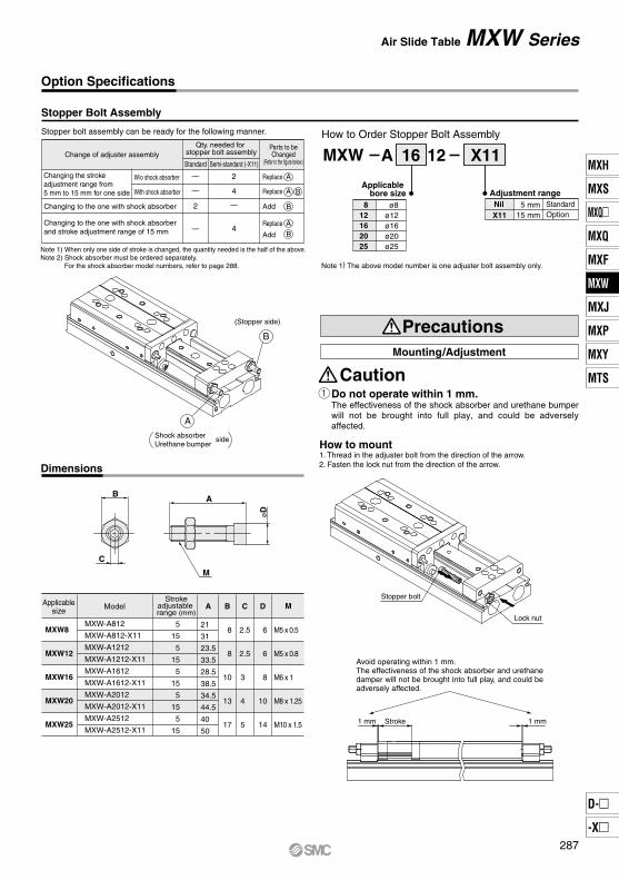
812162025
ø8ø12ø16ø20ø25
X11
Adjustment range
MXW A 16 12 X11
5 mm15 mm
Stopper Bolt Assembly
Stopper bolt assembly can be ready for the following manner.
Change of adjuster assembly
Changing to the one with shock absorber
Changing to the one with shock absorberand stroke adjustment range of 15 mm
W/o shock absorber
With shock absorber
—
—
2
—
2
4
—
4
MXW8
MXW12
MXW16
MXW20
MXW25
MXW-A812
MXW-A812-X11
MXW-A1212
MXW-A1212-X11
MXW-A1612
MXW-A1612-X11
MXW-A2012
MXW-A2012-X11
MXW-A2512
MXW-A2512-X11
5
15
5
15
5
15
5
15
5
15
A
21
31
23.5
33.5
28.5
38.5
34.5
44.5
40
50
B
8
8
10
13
17
C
2.5
2.5
3
4
5
D
6
6
8
10
14
M5 x 0.5
M5 x 0.8
M6 x 1
M8 x 1.25
M10 x 1.5
Note 1) The above model number is one adjuster bolt assembly only.
How to Order Stopper Bolt Assembly
How to mount1. Thread in the adjuster bolt from the direction of the arrow.2. Fasten the lock nut from the direction of the arrow.
A
B
(Stopper side)
B
C
M
A
øD
Stopper bolt
Lock nut
1 mm1 mm Stroke
Do not operate within 1 mm.The effectiveness of the shock absorber and urethane bumper will not be brought into full play, and could be adversely affected.
Mounting/Adjustment
Caution
Precautions
Dimensions
Qty. needed for stopper bolt assembly
Standard Semi-standard (-X11)
Parts to beChanged
(Refer to the figure below.)
Replace A
Replace A B
Replace A
B
Add B
Add
Changing the strokeadjustment range from5 mm to 15 mm for one side
Note 1) When only one side of stroke is changed, the quantity needed is the half of the above.Note 2) Shock absorber must be ordered separately.
For the shock absorber model numbers, refer to page 288.
Shock absorberUrethane bumper
side
Applicablesize Model
Strokeadjustable range (mm)
Applicable bore size
Nil StandardOption
Avoid operating within 1 mm.The effectiveness of the shock absorber and urethane damper will not be brought into full play, and could be adversely affected.
M
Option Specifications
MXW SeriesAir Slide Table
287
MXH
MXS
MXQ
MXQ
MXF
MXW
MXJ
MXP
MXY
MTS
D-
-X
MXW

Shock Absorber
Specifications
MXW8
0.98
5
80
245
1.96
3.83
15
MXW12
2.94
6
80
245
1.96
4.22
15
MXW16
5.88
7
0.05 to 5
70
422
–10 to 80
4.22
6.86
25
MXW20
19.6
12
45
814
6.86
15.98
65
MXW25
58.8
15
25
1961
8.34
20.50
150
How to Replace
How to Remove
How to Mount
Recommended Tightening Torque
MXW8
MXW12
MXW16
MXW20
MXW25
M3 x 4
M3 x 4
M3 x 4
M4 x 5
M5 x 6
0.6
0.6
0.6
0.8
1
1.5
1.5
1.5
2
2.5
RB0805-X552
RB0806-X552
RB1007-X552
RB1412-X552
RB2015-X552
1. Standard
A
2. With shock absorber (Option)
Shock absorber
Urethane bumper
B
A
Lock nut
Lock nut
Stroke adjustment
Do not operate in such a state that the stopper blocks and stopper bolts on both sides are removed.Doing so could create shocks, which could loosen and cause damage.
Adjustment
Caution
Caution
Precautions
Note) The shock absorber service life is different from that of the MXW cylinderdepending on operating conditions. Refer to the Specific Product Precautions for the replacement period.
Shock absorber model
Applicable slide table
Max. absorbing energy (J)
Stroke absorption (mm)
Max. collision speed (m/sec)
Max. operating frequency (cycle/min)
Max. allowable thrust (N)
Ambient temperature range ( )
Spring force (N)
Weight (g)
Extended
Retracted
2. Remove the shock absorbers.
Shock adjuster block ∗
Shock adjuster block ∗
1. Loosen the shock absorber fixing screws.
∗ In the case of MXW8-25, first take out the adjuster block, and then the shock absorber.Tighten the mounting bolt with the torque 0.3 N·m when assembling the adjuster block.
1. Mount the shock absorbers.
2. Tighten the shock absorber fixing screws with the recommended torque shown in the table below.
Insert to the end of the mounting hole of table.
Model Shock absorberfixing thread size
Recommended tighteningtorque (N·m)
Hexagon wrenchwidth across flats (mm)
Loosen the stopper bolt lock nut on side , insert a wrench in the direction of the arrow to adjust the stroke, and then tighten the lock nut.
A
Stroke adjustment Loosen the stopper bolt lock nut on side , insert a wrench in the direction
of the arrow to adjust the stroke, and then tighten the lock nut.B
AStroke absorption adjustment for shock absorber Loosen the stopper bolt lock nut on side , insert a wrench in the direction
of the arrow to adjust the stroke, and then tighten the lock nut.
Service Life and Replacement Period of Shock Absorber
Note) Specified service life (suitable replacement period) is the value at room temperature (20 to 25°C). The period may vary depending on the temperature and other conditions. In some cases the absorber may need to be replaced before the allowable operating cycle above.
1.2 million cycles RB082 million cycles RB1007 to RB2015
1. Allowable operating cycle under the specificationsset in this catalog is shown below.
Option Specifications
MXW Series
288
123456789
1011121314151617181920
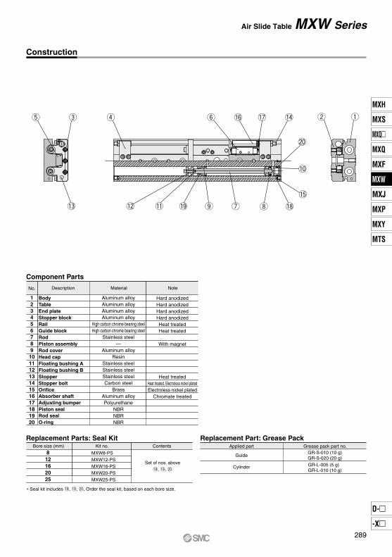
Component Parts
BodyTableEnd plateStopper blockRailGuide blockRodPiston assemblyRod coverHead capFloating bushing AFloating bushing BStopperStopper boltOrificeAbsorber shaftAdjusting bumperPiston sealRod sealO-ring
Hard anodizedHard anodizedHard anodizedHard anodizedHeat treatedHeat treated
With magnet
Heat treatedHeat treated, Electroless nickel platedElectroless nickel plated
Chromate treated
Replacement Parts: Seal Kit Replacement Part: Grease PackBore size (mm)
MXW8-PSMXW12-PSMXW16-PSMXW20-PSMXW25-PS
812162025
Kit no. Contents
Aluminum alloyAluminum alloyAluminum alloyAluminum alloy
High carbon chrome bearing steelHigh carbon chrome bearing steel
Stainless steel—
Aluminum alloyResin
Stainless steelStainless steelStainless steelCarbon steel
BrassAluminum alloyPolyurethane
NBRNBRNBR
No. Description Material Note
Set of nos. above!8, !9, @0
∗ Seal kit includes !8, !9, @0, Order the seal kit, based on each bore size.
Applied part
Guide
Cylinder
Grease pack part no.GR-S-010 (10 g)GR-S-020 (20 g)GR-L-005 (5 g) GR-L-010 (10 g)
!3 !2 !1 !9 !8o u i
!5
!0
@0
!4!7!6yret w q
Construction
MXW SeriesAir Slide Table
289
MXH
MXS
MXQ
MXQ
MXF
MXW
MXJ
MXP
MXY
MTS
D-
-X
MXW
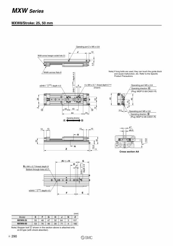
25
84
40
24
Operating direction BA
MXW8-25
MXW8-50
E
55
53
F
48
76
G
47
46
H
32
30
N
3
4
J
64
71
Width across hexagon socket hole 2.5
Width across flats 8
Operating port 2 x M5 x 0.8
J 10
5.5
6 4 x M4 x 0.7 thread depth 6 Note)
Y Y
385
Operating port M5 x 0.8
Operating port M5 x 0.8
19
46
5.5
4
49
7
ø7
ø6.5
14.8
13
3
10
A
15.8
30
A Z
10 13
24
Bottom through-hole ø3.3
N x M4 x 0.7 thread depth 8
(N-1) x H G H
6
F E
Z
157
182
2212
Cross section AA
Note) If long bolts are used, they can touch the guide block and cause malfunction, etc. Refer to the Specific Product Precautions.
ø5H9 ( + 0.0300 ) depth 4.5
5H9
( + 0
.030
0)
dept
h 4.
5
AOperating direction
BOperating direction
(Plug: MGP12-08-CA001-R)
(Plug: MGP12-08-CA001-R)
ø5H9 ( + 0.0300 ) depth 4.5
5H9
(
) +
0.0
300
dept
h 4.
5
Model
Note) Stopper bolt Y shown in the section above is attached only on B type (with shock absorber).
(mm)
(Insert)
MXW8/Stroke: 25, 50 mm
MXW Series
290A
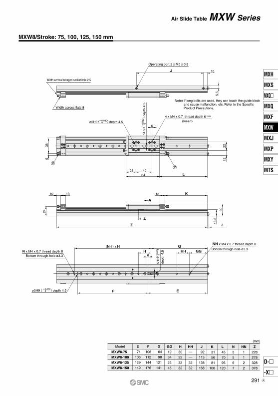
MXW8-75
MXW8-100
MXW8-125
MXW8-150
E
71
106
129
149
F
106
112
144
176
G
64
98
121
141
GG
19
34
25
45
H
30
32
32
32
HH—
—
32
32
K
31
56
81
106
L
45
70
95
120
N
5
5
6
7
Z
228
278
328
378
J
92
115
138
168
NN
1
1
2
2
Width across hexagon socket hole 2.5
Width across flats 8
Operating port 2 x M5 x 0.8
J 10
5.5
2212
4 x M4 x 0.7 thread depth 6 Note)
6
25 4084 L
YY
385
10 13
24
A
3Z
A
15.8
30
13 K
NN x M4 x 0.7 thread depth 8
Bottom through-hole ø3.3
F E
(N-1) x H GH
6GGHH
Bottom through-hole ø3.3N x M4 x 0.7 thread depth 8
ø5H9 (+ 0.0300 ) depth 4.5
5H9
(+ 0
.030
0)
dept
h 4.
5
5H9
(
)
+
0.03
00
dept
h 4.
5
ø5H9 ( + 0.0300 ) depth 4.5
Model
(mm)
Note) If long bolts are used, they can touch the guide block and cause malfunction, etc. Refer to the Specific Product Precautions.
(Insert)
MXW8/Stroke: 75, 100, 125, 150 mm
MXW SeriesAir Slide Table
291
MXH
MXS
MXQ
MXQ
MXF
MXW
MXJ
MXP
MXY
MTS
D-
-X
MXW
A
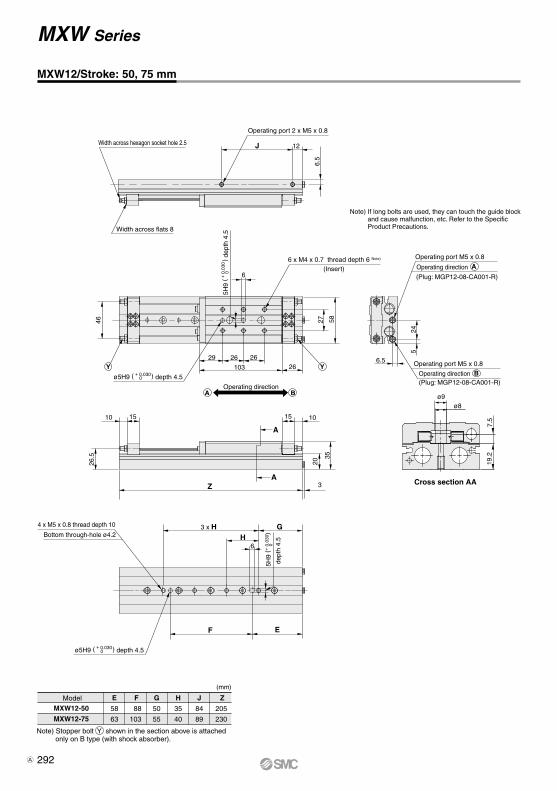
MXW12-50
MXW12-75
E
58
63
F
88
103
G
50
55
H
35
40
J
84
89
Z
205
230
Width across hexagon socket hole 2.5
Width across flats 8
Operating port 2 x M5 x 0.8
J 12
6.5
46
6
27 58
29 26
103
2626
10 15 15 10
A
3
26.5
20
35
Z A
3 x H G H
6
F E
524
6.5
7.5
19.2
ø9 ø8
Cross section AA
Operating directionBA
YY
Operating port M5 x 0.8
Operating port M5 x 0.8
AOperating direction
BOperating direction
(Plug: MGP12-08-CA001-R)
(Plug: MGP12-08-CA001-R)
6 x M4 x 0.7 thread depth 6 Note)
ø5H9 ( + 0.0300 ) depth 4.5
5H9
( + 0
.030
0)
dept
h 4.
5
Bottom through-hole ø4.2
4 x M5 x 0.8 thread depth 10
ø5H9 ( + 0.0300 ) depth 4.5
5H9
(
)
+
0.0
300
Model
Note) Stopper bolt Y shown in the section above is attached only on B type (with shock absorber).
(mm)
Note) If long bolts are used, they can touch the guide block and cause malfunction, etc. Refer to the Specific Product Precautions.
(Insert)
MXW12/Stroke: 50, 75 mm
MXW Series
dept
h 4.
5
292A
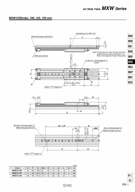
MXW12-100
MXW12-125
MXW12-150
E
91
111
136
F
123
158
182
G
82.5
102.5
127.5
GG
30
32.5
47.5
H
35
35
40
J
114
137
164
K
35
60
85
L
51
76
101
N
5
6
6
Z
280
330
380
46
6
27 58
29 26103
26L
10 15 15 K
26.5 A
20
35
Z
A
3
(N-1) x H G H
6
F E
GG
Width across hexagon socket hole 2.5
Width across flats 8
J 12
6.5
YY
Operating port 2 x M5 x 0.8
6 x M4 x 0.7 thread depth 6 Note)
ø5H9 ( + 0.0300 ) depth 4.5
5H9
(+ 0.
030
0) d
epth
4.5
M5 x 0.8 thread depth 10
Bottom through-hole ø4.2
5H9
(
)
+
0.03
00
dept
h 4.
5Bottom through-hole ø4.2N x M5 x 0.8 thread depth 10
ø5H9 ( + 0.0300 ) depth 4.5
Model
(mm)
Note) If long bolts are used, they can touch the guide block and cause malfunction, etc. Refer to the Specific Product Precautions.
(Insert)
MXW12/Stroke: 100, 125, 150 mm
MXW SeriesAir Slide Table
293
MXH
MXS
MXQ
MXQ
MXF
MXW
MXJ
MXP
MXY
MTS
D-
-X
MXW
A
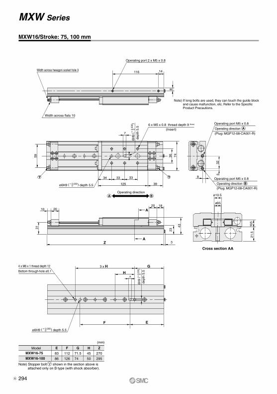
MXW16-75
MXW16-100
E
83
86
F
112
126
G
71.5
74
H
45
50
Z
270
295
Width across hexagon socket hole 3
Width across flats 10
Operating port 2 x M5 x 0.8
116 14
8
59
7
36
34 33
125
33
39
8
10 2020 18
A
31 43
Z A
3
10.5
ø10.5
ø9.5
3 x H G
H7
F E
74
21.5
23
BA
Y Y
532
Note) If long bolts are used, they can touch the guide block and cause malfunction, etc. Refer to the Specific Product Precautions.
Operating port M5 x 0.8
Operating port M5 x 0.8
AOperating direction
BOperating direction
(Plug: MGP12-08-CA001-R)
(Plug: MGP12-08-CA001-R)
Cross section AA
Operating direction
6 x M5 x 0.8 thread depth 9 Note)
ø6H9 ( + 0.0300 ) depth 5.5
6H9
(
)
+
0.0
300
dept
h 5.
5
(Insert)
Bottom through-hole ø5.1
4 x M6 x 1 thread depth 12
ø6H9 ( + 0.0300 ) depth 5.5
6H9
(
)
+
0.03
00
dept
h 5.
5
(mm)
Model
Note) Stopper bolt Y shown in the section above is attached only on B type (with shock absorber).
MXW16/Stroke: 75, 100 mm
MXW Series
294A

MXW16-125
MXW16-150
MXW16-175
MXW16-200
Z
345
395
445
495
NN
1
1
2
2
N
5
5
6
6
L
64
89
114
139
K
43
68
93
118
J
141
166
191
216
HH—
—
45
50
H
45
50
45
50
GG
31.5
24
39
24
G
99
124
151.5
174
F
157
176
202
226
E
110
136
163
186
J 14
8
59
7
36 74
34 33
125
33
L
10 20
31
(N-1) x H G
H7
F E
GG
20 K
A
23
43
Z A
3
HHNN x M6 x 1 thread depth 12
Y Y
Width across hexagon socket hole 3
Width across flats 10
Operating port 2 x M5 x 0.8
Note) If long bolts are used, they can touch the guide block and cause malfunction, etc. Refer to the Specific Product Precautions.
6 x M5 x 0.8 thread depth 9 Note)
ø6H9 ( + 0.0300 ) depth 5.5
6H9
(
)
+
0.0
300
dept
h 5.
5 (Insert)
Bottom through-hole ø5.1
6H9
(
)
+ 0.
030
0
dept
h 5.
5Bottom through-hole ø5.1
N x M6 x 1 thread depth 12
ø6H9 ( + 0.0300 ) depth 5.5
Model
(mm)
MXW16/Stroke: 125, 150, 175, 200 mm
MXW SeriesAir Slide Table
295
MXH
MXS
MXQ
MXQ
MXF
MXW
MXJ
MXP
MXY
MTS
D-
-X
MXW
A
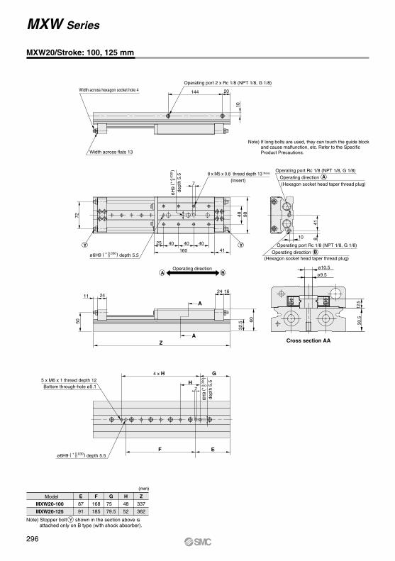
Z
337
362
H
48
52
G
75
79.5
F
168
185
E
87
91
MXW20-100
MXW20-125
Operating port 2 x Rc 1/8 (NPT 1/8, G 1/8)
144 20
10
72
7
4825
160
40
4198
Operating port Rc 1/8 (NPT 1/8, G 1/8)
41
ø10.5
ø9.5
30.5
11 2424 16
A
50 60
ZA
32.5
4 x H G
H7
F E
4040
12.5
10
BA
Y Y
(Hexagon socket head taper thread plug)
Operating port Rc 1/8 (NPT 1/8, G 1/8)
(Hexagon socket head taper thread plug)
8
Width across hexagon socket hole 4
Width across flats 13
Note) If long bolts are used, they can touch the guide block and cause malfunction, etc. Refer to the Specific Product Precautions.
AOperating direction
BOperating direction
Cross section AA
ø6H9 ( + 0.0300 ) depth 5.5
6H9
(
)
+
0.0
300
dept
h 5.
5
Operating direction
8 x M5 x 0.8 thread depth 13 Note)
(Insert)
Bottom through-hole ø5.15 x M6 x 1 thread depth 12
ø6H9 ( + 0.0300 ) depth 5.5
6H9
(
)
+
0.03
00
dept
h 5.
5
(mm)
Model
Note) Stopper bolt Y shown in the section above is attached only on B type (with shock absorber).
MXW20/Stroke: 100, 125 mm
MXW Series
296
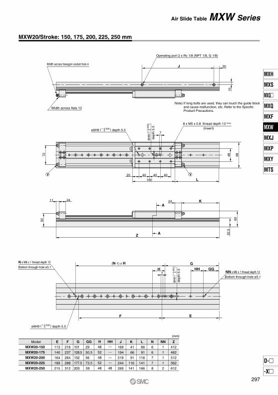
H
48
52
48
52
48
Z
412
462
512
562
612
NN
1
1
1
1
2
N
6
6
7
7
8
L
66
91
116
141
166
K
41
66
91
116
141
J
169
194
219
244
269
HH—
—
—
—
48
GG
29
50.5
56
73.5
59
G
101
128.5
152
177.5
203
F
216
237
264
288
312
E
113
140
164
189
215
MXW20-150
MXW20-175
MXW20-200
MXW20-225
MXW20-250
J 20
10
72
7
48 98
25
160
40L
11 24
50
24 KA
32.5
Z A
(N-1) x H G H
7
F E
GGHH
4040
60
YY
Operating port 2 x Rc 1/8 (NPT 1/8, G 1/8)
Width across hexagon socket hole 4
Width across flats 13
Note) If long bolts are used, they can touch the guide block and cause malfunction, etc. Refer to the Specific Product Precautions.
ø6H9 ( + 0.0300 ) depth 5.5
6H9
(
)
+
0.0
300
dept
h 5.
5
8 x M5 x 0.8 thread depth 13 Note)
(Insert)
NN x M6 x 1 thread depth 12
Bottom through-hole ø5.1
6H9
(
)
+
0.03
00
dept
h 5.
5
Bottom through-hole ø5.1
N x M6 x 1 thread depth 12
ø6H9 ( + 0.0300 ) depth 5.5
Model
(mm)
MXW20/Stroke: 150, 175, 200, 225, 250 mm
MXW SeriesAir Slide Table
297
MXH
MXS
MXQ
MXQ
MXF
MXW
MXJ
MXP
MXY
MTS
D-
-X
MXW
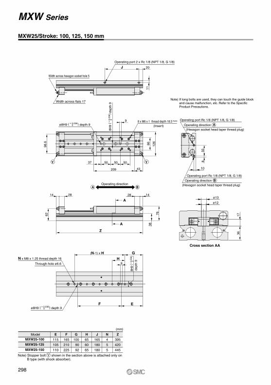
MXW25-100
MXW25-125
MXW25-150
E
115
105
110
F
165
210
225
G
100
90
92
H
65
60
65
N
4
5
5
J
165
180
180
Z
395
420
445
J 20
1166 12
6
209
50
43
5037 Y50Y
98.6
9
558
10
BA
76
38
A
A
28 14
Z
62
2814ø13
ø12
1736
Through-hole ø6.6
N x M8 x 1.25 thread depth 16
(N-1) x H G
H9
F E
Operating port 2 x Rc 1/8 (NPT 1/8, G 1/8)
Width across hexagon socket hole 5
Width across flats 17 Note) If long bolts are used, they can touch the guide block
and cause malfunction, etc. Refer to the Specific Product Precautions.
Operating port Rc 1/8 (NPT 1/8, G 1/8)
(Hexagon socket head taper thread plug)
Operating port Rc 1/8 (NPT 1/8, G 1/8)
(Hexagon socket head taper thread plug)
BOperating direction
Cross section AA
AOperating direction ø8H9 ( + 0.0360 ) depth 9
8H9
(
)
+
0.0
360
dept
h 9
8 x M6 x 1 thread depth 18.5 Note)
(Insert)
Operating direction
ø8H9 ( + 0.0360 ) depth 9
8H9
(
)
+
0.03
60
dept
h 9
(mm)
Model
Note) Stopper bolt Y shown in the section above is attached only on B type (with shock absorber).
MXW25/Stroke: 100, 125, 150 mm
MXW Series
298
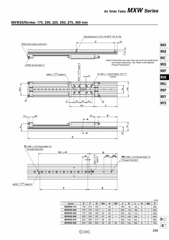
MXW25-175
MXW25-200
MXW25-225
MXW25-250
MXW25-275
MXW25-300
E
120
155
175
200
225
245
F
270
275
305
335
360
395
G
105
142
165
187
210
232
GG—
—
55
67
80
52
H
60
60
55
60
65
60
HH—
—
—
—
—
60
K
34
59
84
109
134
159
L
63
88
113
138
163
188
N
6
6
7
7
7
8
Z
490
540
590
640
690
740
J
195
225
245
275
300
320
NN—
—
1
1
1
2
J 20
1166 12
6
209
50
L
5037 Y50Y
9
98.6
62
14 28
Z
A
A
28 K
38
76
(N-1) x H G
H9
GGHH
EF
Operating port 2 x Rc 1/8 (NPT 1/8, G 1/8)
Width across hexagon socket hole 5
Width across flats 17
Note) If long bolts are used, they can touch the guide block and cause malfunction, etc. Refer to the Specific Product Precautions.
ø8H9 ( + 0.0360 ) depth 9
8H9
(
)
+
0.0
360
dept
h 9
8 x M6 x 1 thread depth 18.5 Note)
(Insert)
Through-hole ø6.6N x M8 x 1.25 thread depth 16
ø8H9 ( + 0.0360 ) depth 9
8H9
(
)
+
0.03
60
dept
h 9 NN x M8 x 1.25 thread depth 16
Through-hole ø6.6
Model
(mm)
MXW25/Stroke: 175, 200, 225, 250, 275, 300 mm
MXW SeriesAir Slide Table
299
MXH
MXS
MXQ
MXQ
MXF
MXW
MXJ
MXP
MXY
MTS
D-
-X
MXW
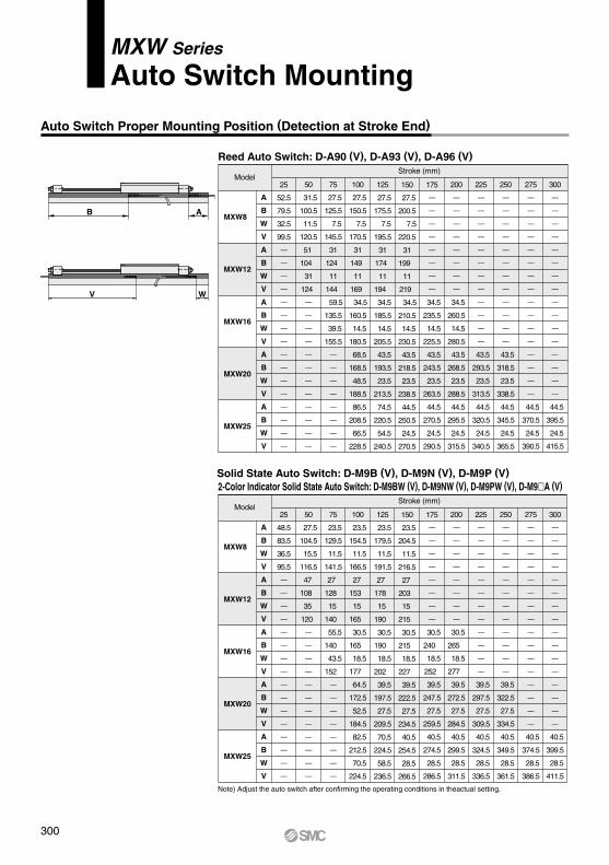
MXW Series
Auto Switch Mounting
B A
WV
Reed Auto Switch: D-A90 (V), D-A93 (V), D-A96 (V)
MXW8
MXW12
MXW16
MXW20
MXW25
A
B
W
V
A
B
W
V
A
B
W
V
A
B
W
V
A
B
W
V
25
52.5
79.5
32.5
99.5
—
—
—
—
—
—
—
—
—
—
—
—
—
—
—
—
50
31.5
100.5
11.5
120.5
51
104
31
124
—
—
—
—
—
—
—
—
—
—
—
—
75
27.5
125.5
7.5
145.5
31
124
11
144
59.5
135.5
39.5
155.5
—
—
—
—
—
—
—
—
100
27.5
150.5
7.5
170.5
31
149
11
169
34.5
160.5
14.5
180.5
68.5
168.5
48.5
188.5
86.5
208.5
66.5
228.5
125
27.5
175.5
7.5
195.5
31
174
11
194
34.5
185.5
14.5
205.5
43.5
193.5
23.5
213.5
74.5
220.5
54.5
240.5
150
27.5
200.5
7.5
220.5
31
199
11
219
34.5
210.5
14.5
230.5
43.5
218.5
23.5
238.5
44.5
250.5
24.5
270.5
175
—
—
—
—
—
—
—
—
34.5
235.5
14.5
225.5
43.5
243.5
23.5
263.5
44.5
270.5
24.5
290.5
200
—
—
—
—
—
—
—
—
34.5
260.5
14.5
280.5
43.5
268.5
23.5
288.5
44.5
295.5
24.5
315.5
225
—
—
—
—
—
—
—
—
—
—
—
—
43.5
293.5
23.5
313.5
44.5
320.5
24.5
340.5
250
—
—
—
—
—
—
—
—
—
—
—
—
43.5
318.5
23.5
338.5
44.5
345.5
24.5
365.5
275
—
—
—
—
—
—
—
—
—
—
—
—
—
—
—
—
44.5
370.5
24.5
390.5
300
—
—
—
—
—
—
—
—
—
—
—
—
—
—
—
—
44.5
395.5
24.5
415.5
Stroke (mm)
2-Color Indicator Solid State Auto Switch: D-M9BW (V), D-M9NW (V), D-M9PW (V), D-M9A (V)
MXW8
MXW12
MXW16
MXW20
MXW25
A
B
W
V
A
B
W
V
A
B
W
V
A
B
W
V
A
B
W
V
25
48.5
83.5
36.5
95.5
—
—
—
—
—
—
—
—
—
—
—
—
—
—
—
—
50
27.5
104.5
15.5
116.5
47
108
35
120
—
—
—
—
—
—
—
—
—
—
—
—
75
23.5
129.5
11.5
141.5
27
128
15
140
55.5
140
43.5
152
—
—
—
—
—
—
—
—
100
23.5
154.5
11.5
166.5
27
153
15
165
30.5
165
18.5
177
64.5
172.5
52.5
184.5
82.5
212.5
70.5
224.5
125
23.5
179.5
11.5
191.5
27
178
15
190
30.5
190
18.5
202
39.5
197.5
27.5
209.5
70.5
224.5
58.5
236.5
150
23.5
204.5
11.5
216.5
27
203
15
215
30.5
215
18.5
227
39.5
222.5
27.5
234.5
40.5
254.5
28.5
266.5
175
—
—
—
—
—
—
—
—
30.5
240
18.5
252
39.5
247.5
27.5
259.5
40.5
274.5
28.5
286.5
200
—
—
—
—
—
—
—
—
30.5
265
18.5
277
39.5
272.5
27.5
284.5
40.5
299.5
28.5
311.5
225
—
—
—
—
—
—
—
—
—
—
—
—
39.5
297.5
27.5
309.5
40.5
324.5
28.5
336.5
250
—
—
—
—
—
—
—
—
—
—
—
—
39.5
322.5
27.5
334.5
40.5
349.5
28.5
361.5
275
—
—
—
—
—
—
—
—
—
—
—
—
—
—
—
—
40.5
374.5
28.5
386.5
300
—
—
—
—
—
—
—
—
—
—
—
—
—
—
—
—
40.5
399.5
28.5
411.5
Stroke (mm)
Model
Model
Solid State Auto Switch: D-M9B (V), D-M9N (V), D-M9P (V)
Note) Adjust the auto switch after confirming the operating conditions in theactual setting.
Auto Switch Proper Mounting Position (Detection at Stroke End)
300
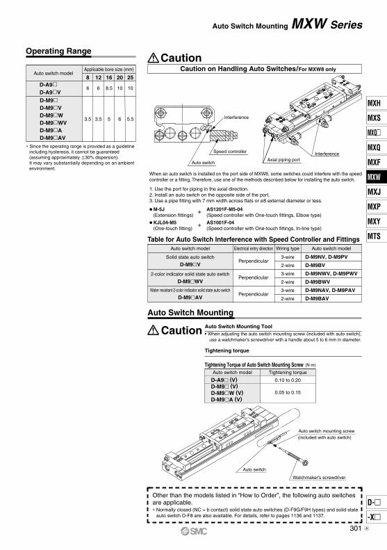
Auto Switch Mounting Tool• When adjusting the auto switch mounting screw (included with auto switch),
use a watchmaker’s screwdriver with a handle about 5 to 6 mm in diameter.
Tightening torque
Solid state auto switch
D-M9V
2-color indicator solid state auto switch
D-M9WV
Water resistant 2-color indicator solid state auto switch
D-M9AV
Perpendicular
Perpendicular
Perpendicular
3-wire
2-wire
3-wire
2-wire
3-wire
2-wire
D-M9NV, D-M9PV
D-M9BV
D-M9NWV, D-M9PWV
D-M9BWV
D-M9NAV, D-M9PAV
D-M9BAV
Auto switch
Speed controller
Axial piping portInterference
Caution on Handling Auto Switches/For MXW8 only
Caution
D-A9D-A9V
8
6
12
6
16
8.5
20
10
25
10
3.5 3.5 5 6 5.5
Applicable bore size (mm)Auto switch model
D-M9D-M9VD-M9WD-M9WVD-M9AD-M9AV
Tightening Torque of Auto Switch Mounting ScrewAuto switch model Tightening torque
0.10 to 0.20
0.05 to 0.15
D-A9 (V)D-M9 (V)D-M9W (V)D-M9A (V)
(N·m)
Table for Auto Switch Interference with Speed Controller and Fittings
Auto switch mounting screw(included with auto switch)
Watchmaker’s screwdriver
Auto switch
When an auto switch is installed on the port side of MXW8, some switches could interfere with the speed controller or a fitting. Therefore, use one of the methods described below for installing the auto switch.
1. Use the port for piping in the axial direction.2. Install an auto switch on the opposite side of the port.3. Use a pipe fitting with 7 mm width across flats or ø8 external diameter or less.
∗ Since the operating range is provided as a guideline including hysteresis, it cannot be guaranteed (assuming approximately 30% dispersion). It may vary substantially depending on an ambient environment.
M-5J (Extension fittings)
AS1201F-M5-04 (Speed controller with One-touch fittings, Elbow type)
+
KJL04-M5 (One-touch fitting)
AS1001F-04 (Speed controller with One-touch fittings, In-line type)
+
Auto switch model Electrical entry direction Auto switch modelWiring type
∗ Normally closed (NC = b contact) solid state auto switches (D-F9G/F9H types) and solid state auto switch D-F8 are also available. For details, refer to pages 1136 and 1137.
Other than the models listed in “How to Order”, the following auto switchesare applicable.
Operating Range
MXW SeriesAuto Switch Mounting
Auto Switch Mounting
Caution
Interference
301
MXH
MXS
MXQ
MXQ
MXF
MXW
MXJ
MXP
MXY
MTS
D-
-X
MXW
A
Food
Non-food zoneCan be mounted.
Container
Food zoneCannot be mountedSplash zone
Can be mounted
MXW Series
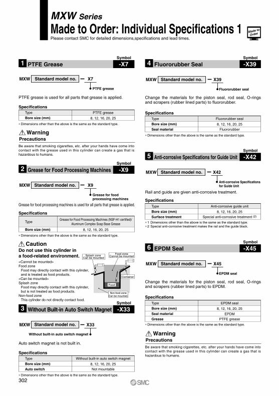
Made to Order: Individual Specifications 1Please contact SMC for detailed dimensions,specifications and lead times.
PrecautionsWarning
Be aware that smoking cigarettes, etc. after your hands have come into contact with the grease used in this cylinder can create a gas that is hazardous to humans.
SpecificationsGrease for Food Processing Machines (NSF-H1 certified)/
Aluminum Complex Soap Base Grease
8, 12, 16, 20, 25
Type
Bore size (mm)
∗ Dimensions other than the above is the same as the standard type.
Caution
<Cannot be mounted>Food zone
Food may directly contact with this cylinder, and is treated as food products.
<Can be mounted>Splash zone
Food may directly contact with this cylinder, but is not treated as food products.
Non-food zoneThis cylinder do not directly contact food.
Do not use this cylinder in a food-related environment.
Symbol
-X7PTFE Grease1Symbol
-X39Fluororubber Seal4
Symbol
-X9Grease for Food Processing Machines2
Symbol
-X33Without Built-in Auto Switch Magnet 3
Symbol
-X42Anti-corrosive Specifications for Guide Unit5
Symbol
-X45EPDM Seal6
SpecificationsPTFE grease
8, 12, 16, 20, 25
Type
Bore size (mm)
MXW X7
PTFE grease is used for all parts that grease is applied.
PTFE grease
∗ Dimensions other than the above is the same as the standard type.
Standard model no.
MXW X9
Grease for food processing machines is used for all parts that grease is applied.
Grease for food processing machines
Standard model no.
SpecificationsWithout built-in auto switch magnet
8, 12, 16, 20, 25
Not mountable
Type
Bore size (mm)
Auto switch
MXW X33
Auto switch magnet is not built in.
Without built-in auto switch magnet
∗ Dimensions other than the above is the same as the standard type.
Standard model no.
MXW X39
Change the materials for the piston seal, rod seal, O-rings and scrapers (rubber lined parts) to fluororubber.
Fluororubber seal
Standard model no.
SpecificationsFluororubber seal
8, 12, 16, 20, 25
Fluororubber
Type
Bore size (mm)
Seal material
∗ Dimensions other than the above is the same as the standard type.
Specifications
MXW X42
Rail and guide are given anti-corrosive treatment.
Anti-corrosive Specifications for Guide Unit
∗ 1 Dimensions other than the above is the same as the standard type.∗ 2 Special anti-corrosive treatment makes the rail and the guide black.
Standard model no.
Anti-corrosive guide unit
8, 12, 16, 20, 25
Special anti-corrosive treatment (2)
Type
Bore size (mm)
Surface treatment
MXW X45
Change the materials for the piston seal, rod seal, O-rings and scrapers (rubber lined parts) to EPDM.
EPDM seal
Standard model no.
Specifications
∗ Dimensions other than the above is the same as the standard type.
EPDM seal
8, 12, 16, 20, 25
EPDM
PTFE grease
Type
Bore size (mm)
Seal material
Grease
PrecautionsWarning
Be aware that smoking cigarettes, etc. after your hands have come into contact with the grease used in this cylinder can create a gas that is hazardous to humans.
Made to
Order
302
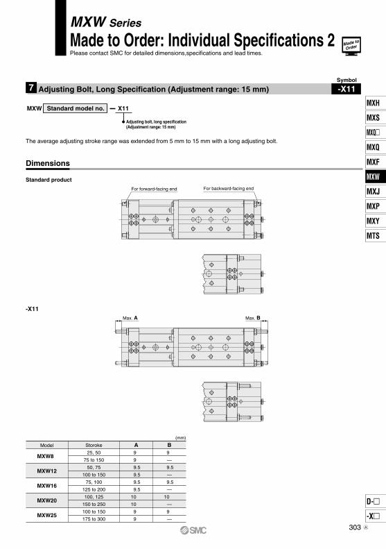
Max. A Max. B
For forward-facing end For backward-facing end
The average adjusting stroke range was extended from 5 mm to 15 mm with a long adjusting bolt.
Model
MXW8
MXW12
MXW16
MXW20
MXW25
(mm)
Storoke
25, 50
75 to 150
50, 75
100 to 150
75, 100
125 to 200
100, 125
150 to 250
100 to 150
175 to 300
B9
—
9.5
—
9.5
—
10
—
9
—
A9
9
9.5
9.5
9.5
9.5
10
10
9
9
Symbol
-X11Adjusting Bolt, Long Specification (Adjustment range: 15 mm)7
MXW Series
Made to Order: Individual Specifications 2Please contact SMC for detailed dimensions,specifications and lead times.
MXW X11
Adjusting bolt, long specification(Adjustment range: 15 mm)
Standard model no.
Standard product
-X11
Dimensions
Made to
Order
303
MXH
MXS
MXQ
MXQ
MXF
MXW
MXJ
MXP
MXY
MTS
D-
-X
MXW
A

H
MXW8
MXW12
MXW16
MXW20
MXW25
M4 x 0.7
M5 x 0.8
M6 x 1
M6 x 1
M8 x 1.25
2.1
4.4
7.4
7.4
18
8
10
12
12
16
Mounting of Body
MXW8
MXW12
MXW16
MXW20
MXW25
2. Through-hole
M3 x 0.5
M4 x 0.7
M5 x 0.8
M5 x 0.8
M6 x 1
1.2
2.1
4.4
4.4
7.4
14.8
19.2
21.5
30.5
36
MXW8
MXW12
MXW16
MXW20
MXW25
M4 x 0.7
M4 x 0.7
M5 x 0.8
M5 x 0.8
M6 x 1
2.1
2.1
4.4
4.4
7.4
Mounting of Workpiece
6
6
9
13
18.5
1. Body tapped
øD
L
H L
øD
H
L
øD
Guide block
Mounting
Caution
Caution
1. Do not apply scratches and dents on mounting side of body and table (guide table).The damage will decrease parallelism, increase vibration of guide and increase moving part resistance.
4. When mounting the body, use screws with appropriate length and do not exceed the maximum tightening torque.Tightening with a torque above the limit could malfunction. Whereas tightening insufficiently could result in misalignment or come to a drop.
3. Keep away from objects which are influenced by magnets.As the piston part has magnets built-in, do not allow close contact with a magnetic disk, magnetic card, or magnetic tape. Data might be erased.
2. Do not scratch or dent on the forward side of the rail.This could result in looseness and increased operating resistance, etc.
The slide table can be mounted from 2 directions. Select the best direction according to application requirement.
Model Bolt Max. tighteningtorque (N·m)
Max. screw-indepth L (mm)
Positioning holeøD x H (mm)
Model Bolt Max. tighteningtorque (N·m)
Depth L (mm)Positioning hole
øD x H (mm)
ø5H9 + 0.0300 depth 4.5
ø8H9 + 0.0360 depth 9
ø5H9 + 0.0300 depth 4.5
ø6H9 + 0.0300 depth 5.5
ø6H9 + 0.0300 depth 5.5
ø5H9 + 0.0300 depth 4.5
ø8H9 + 0.0360 depth 9
ø5H9 + 0.0300 depth 4.5
ø6H9 + 0.0300 depth 5.5
ø6H9 + 0.0300 depth 5.5
1. To prevent the workpiece holding bolts from touching the guide block, use bolts that are 0.5 mm or more shorter than the maximum screw-in depth. If the bolts are too long, they come in contact with the guide block, which could lead to a malfunction.
3. The positioning hole on the table and on the bottom of the body does not have the same center.Use these holes during reinstallation after the table has been removed for the maintenance of an identical product.
Model Bolt Max. tighteningtorque (N·m)
Max. screw-indepth L (mm)
Positioning holeøD x H (mm)
ø5H9 + 0.0300 depth 4.5
ø8H9 + 0.0360 depth 9
ø5H9 + 0.0300 depth 4.5
ø6H9 + 0.0300 depth 5.5
ø6H9 + 0.0300 depth 5.5
2. 0.02 mm or less of flatness is recommended for the body mounting surface. Insufficient flatness of workpiece or base to which Air Slide Table is mounted can generate play in guide section or increase of sliding resistance.
MXW SeriesSpecific Product PrecautionsBe sure to read this before handling the products. Refer to back page 50 for Safety Instructions and pages 3 to 12 for Actuator and Auto Switch Precautions.
304