AIR QUALITY SURVEILLANCE BRANCH STANDARD OPERATING ... · PDF fileAIR QUALITY SURVEILLANCE...
29
AIR QUALITY SURVEILLANCE BRANCH STANDARD OPERATING PROCEDURES FOR MET ONE INSTRUMENTS Speciation Air Sampling System (SASS) AQSB SOP 401 First Edition MONITORING AND LABORATORY DIVISION February 2003
-
Upload
truongnguyet -
Category
Documents
-
view
218 -
download
0
Transcript of AIR QUALITY SURVEILLANCE BRANCH STANDARD OPERATING ... · PDF fileAIR QUALITY SURVEILLANCE...
AIR QUALITY SURVEILLANCE BRANCH
STANDARD OPERATING PROCEDURES
FOR
MET ONE INSTRUMENTSSpeciation Air Sampling System
(SASS)
AQSB SOP 401
First Edition
MONITORING AND LABORATORY DIVISION
February 2003
Approval of Standard Operating Procedures (SOP)
Title: Met One Instruments Speciation Air Sampling System (SASS)
SOP: AQBS SOP 401, First Edition
Section: Operation Support Section (OSS)
Branch: Air Quality Surveillance Branch (AQSB)
Division: Monitoring and Laboratory Division (MLD)
Prepared by: Matthew Quok
Approval: This SOP has been reviewed and approved by:
Reginald L. Smith, Manager DateOperation Support SectionAir Quality Surveillance Branch
Kenneth R. Stroud, Chief DateAir Quality Surveillance Branch
mjackson
//s//
mjackson
//s//
mjackson
5/20/03
mjackson
5/20/03
3
TABLE OF CONTENTS
MET ONE INSTRUMENTSSPECIATION AIR SAMPLING SYSTEM (SASS)
Page(s) Date
1.0 GENERAL INFORMATION 6-8 2/03
1.1 Purpose 61.2 General Description and Theory of Operation 61.3 Safety 8
2.0 INSTALLATION PROCEDURE 9-10 2/03
2.1 Physical Inspection 92.2 Siting 92.3 Tools 92.4 Tripod Assembly 92.5 Sampling Head Installation 92.6 Control Unit and Temperature Sensor 10
Mounting2.7 Pump Box Mounting 102.8 Sampling Canister Mounting 10
3.0 CONFIGURATION 12 2/03
3.1 Time and Date Setup 123.2 Event Setup 12
4.0 SAMPLE PREPARATION AND SHIPMENT 13 2/03
4.1 Canister Handling 134.2 SCC Inlets 134.3 Field Blanks 13
AQSB SOP 401Met One Sass
First Edition, February 2003
4
TABLE OF CONTENTS (cont’d)
Page(s) Date
5.0 DATA RETRIEVAL 14 2/03
5.1 General Information 145.2 Hardware Setup 145.3 SASSCom AQ Software 14
6.0 CALIBRATION PROCEDURES 15-20 2/03
6.1 General Information 156.2 Apparatus for Met One SASS Calibration 156.3 Pre-Calibration Preparations 156.4 Time Verification 166.5 Ambient Temperature Sensor Calibration 166.6 Filter Temperature Sensor Calibration 176.7 Pressure Sensor Calibration 186.8 Leak Test 186.9 Flow Calibration Setup 196.10 Flow Calibration 19
7.0 VERIFICATION PROCEDURES 21-23 2/03
7.1 General Information 217.2 Ambient Temperature Sensor Verification 217.3 Filter Temperature Sensor Verification 217.4 Pressure Sensor Verification 227.5 Flow Verification 227.6 Leak Check 23
8.0 ROUTINE SERVICE CHECKS 24 2/03
8.1 General Information 248.2 Daily Checks 248.3 Monthly Checks 248.4 Semi-Annual Checks 24
AQSB SOP 401Met One Sass
First Edition, February 2003
5
TABLE OF CONTENTS (cont’d)
Page(s) Date
9.0 MAINTENANCE PROCEDURES 25 2/03
9.1 General Information 259.2 Sampler Maintenance 259.3 PM2.5 Sharp Cut Cyclone (SCC) 25
Maintenance9.4 Pump Box Maintenance 25
10.0 TROUBLESHOOTING 26 2/03
10.1 General Information 26
FIGURES
FIGURE 1 - Schematic of Met One SASS Sampler .............. 7
APPENDICES
CARB Monthly Quality Control Maintenance Check Sheet .... Appendix AMet One SASS Calibration Report ......................................... Appendix BPM 2.5 Speciation Custody and Field Data Form .................. Appendix C
AQSB SOP 401Met One Sass
First Edition, February 2003
6
1.0 GENERAL INFORMATION
1.1 Purpose:
The purpose of this Standard Operating Procedure (SOP) is to supplement theMet One Speciation Air Sampling System (SASS) Operator’s Manual bydescribing modifications in hardware or operating procedures which may havebeen implemented by the Monitoring and Laboratory Division of the AirResources Board (ARB). These modifications are designed to assurecompliance with the Federal Reference Method (FRM) for collection of particulatematter 2.5 microns or smaller (PM2.5) when using the Met One Air Sampler. Theintent of this document is not to duplicate the Met One Manual, and whereapplicable, this SOP refers to the Met One SASS operations manual.
1.2 General Description and Theory of Operation:
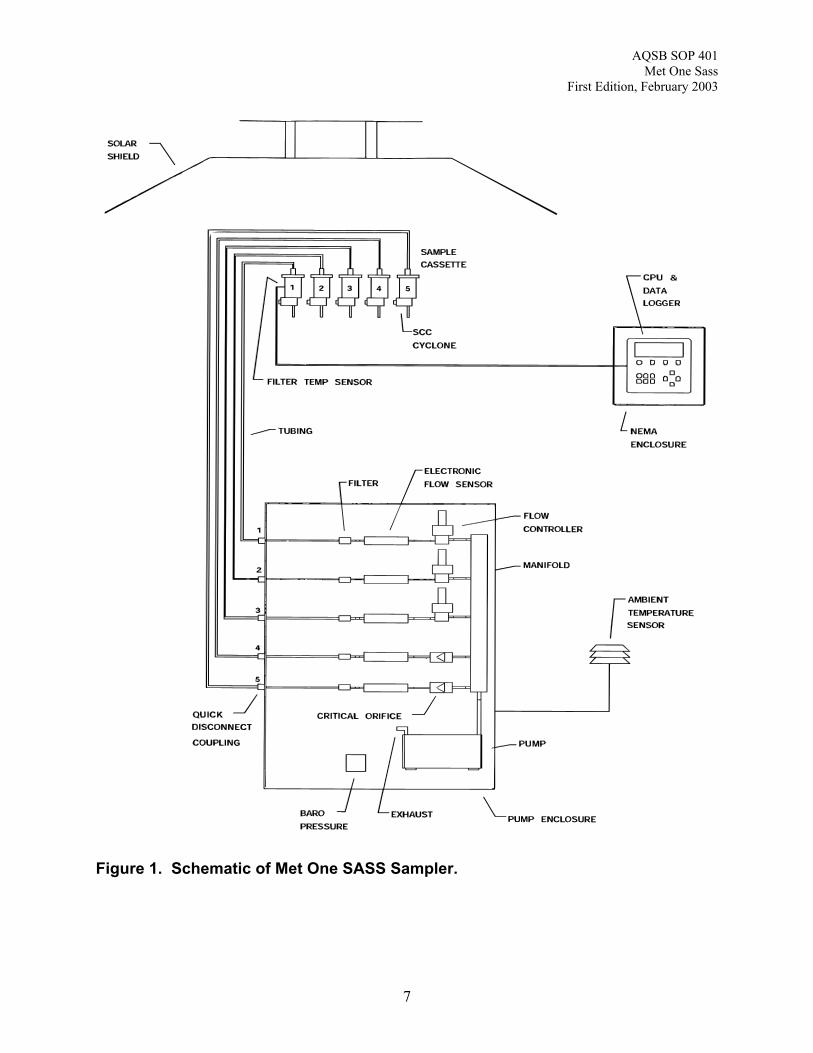
The Met One SASS is a five channel sampler designed to collect PM2.5 on threedifferent collection media for speciation. The sampler operates at a volumetricflow rate of 6.7 liters per minute and provides the PM2.5 cut-point via a sharp cutcyclone. The particles collected on the Teflon filter can be used for mass andmetals analysis. The particles collected on nylon can be used for ion analysis. The particles collected on the quartz fiber filters can be used for carbon analysis. All filters are 47 mm in diameter.
Electronic systems in the sampler are designed to monitor and maintain thevolumetric flow rate as well as record the elapsed sampling time enabling theSASS to calculate the total sample volume in cubic meters (m3). Using thisinformation, the analyzing laboratory will calculate and report the average PM2.5concentration for the sampling period in ug/m3.
The SASS monitors and regulates the flow rates for all the channels using thesampler’s microprocessor, software, mass flow controller, ambient temperaturesensor, and ambient pressure sensor. The valid sampling period must bebetween 23 and 25 hours. The flow rate of the sampler must be 6.7 LPM ± 4%. The sampler, along with the analytical analyses, can generate results for 58different air quality parameters.
Data from a previous run can be downloaded to a laptop or PC via a RS232cable and the SASSCOMM AQ software or the data can be accessed from thescreens on the instrument.
AQSB SOP 401Met One Sass
First Edition, February 2003
7
Figure 1. Schematic of Met One SASS Sampler.
AQSB SOP 401Met One Sass
First Edition, February 2003
8
1.3 Safety:
Think “safety first”. High (120 volts A.C.) voltage is used to power the unit. Watch where and how you place your hands in the sampler. Unplug the samplerwhenever possible while working around electrical components. Workingoutdoors in wet weather conditions increases the risk of electrocution.
Rooftop sampling creates a hazard from falling. Be careful climbing anddescending to and from the rooftop platform. For additional safety informationread Section 2.0 Unpacking, Siting, and Installation Section of the Met OneSASS Operating Manual and the Air Quality Surveillance Branch Safety Manual.
Ensure that the green grounding cable is installed.
AQSB SOP 401Met One Sass
First Edition, February 2003
9
2.0 INSTALLATION PROCEDURE
2.1 Physical Inspection:
Inspect equipment and accessories for completeness and check for any shippingdamage upon receipt of a SASS sampler. If equipment is missing or damage isfound immediately notify your supervisor and/or your agency’s shippingdepartment.
2.2 Siting:
Siting of the SASS will be dictated by the type of sampling to be conducted. Aneffort should be made to meet siting guidelines stated in the Code of FederalRegulations, Title 40 Part 58. Ensure the sampler inlet is separated by at least1m, but not more than 4m, from other PM2.5 samplers and that the sampler hasan unobstructed airflow of a minimum of 2m in all directions. For collocatedsampler studies position the sampler inlets exactly 1 meter apart.
2.3 Tools:
The SASS sampler contains a tool kit that has the equipment necessary forassembly of the sampler. A drill is required to bolt the tripod and pump box to theground. Review the operator’s manual and the steps below completely beforeinstalling.
2.4 Tripod Assembly:
Remove the three pins holding the legs in the upright position. Lower the legsand reinsert the pins to lock the legs in the down position. The tripod must beanchored to the ground to ensure that it will not tip over in strong wind orinclement weather. If the platform is made of wood, 1/3’’ lag screws are advised.
2.5 Sampling Head Installation:
The bottom and top shields of the sampling head are attached when shipped. Detach the bottom shield and slide it past the hoses and cables that are attachedto the upper sampling head. Remove the pin on the side of the bottom shield. Slide the shield down the tripod with the open side of the shield facing upwards.
Find the bag of three 8-32 x 3/16’’ socket head screws in the tool kit. The correctscrews have been treated with a red thread locking compound. Install twoscrews into the two tapped holes in the mast.
Remove the gray PVC shipping tube from the center of the upper sampling head.Unwind the cabling attached to the sampling head. Feed the cables down the
AQSB SOP 401Met One Sass
First Edition, February 2003
10
center of the mast and slide the head onto the mast. Aligning the notch in thesampling head with the upper socket head screw in the mast allows the head toslide completely downward. Tighten the two socket head screws in the samplinghead to secure it to the mast. Raise the bottom shield and align the notch withthe lower set screw in the mast. Put the pin in place to lock the shield in theraised position.
2.6 Control Unit and Temperature Sensor Mounting:
Using two U-bolts, four 7/16” nuts, and four washers, mount the control unit justabove the tripod legs. The control unit will face upwards with the cableconnections on the bottom when properly oriented.
The temperature sensor mounts to the tripod with a U-bolt, two 7/16” nuts, andwashers. Align the top of the probe’s radiation shield with the top of the controlbox. Place the sensor so that it is oriented 180° in relation to the control box.
2.7 Pump Box Mounting:
Place the pump box close to the base of the tripod to ensure that all cableconnections can be made. Anchor the pump box using lag bolts or otherappropriate hardware. There are pre-drilled holes in the legs of the unit for thispurpose.
Plug the pump box power cord into a 110V AC power source. Connect thesensor cable and the control box power cable into the control box. There are 5quick-disconnect valve connectors on the pump box numbered 1-5. Thesenumbers correspond to the channels on the SASS sampling head. Each pumpline from the head is numbered; connect each line to the corresponding quick-disconnect valve. Channels four and five can be connected or the pump linesand valves can be left disconnected. If channels four and five are disconnected,place the orange caps over the sample lines. Connect the green and yellowgrounding cable to an appropriate ground source.
2.8 Sample Canister Mounting:
The sample canisters will contain the necessary filters and denuders when theyarrive from the laboratory. The sharp-cut cyclone inlets (SCC) must be installedand the sample canisters must be placed onto the appropriate channels in thesampling head. Placing a very small amount of o-ring lubricant (silicone grease)on the o-rings will facilitate insertion of the cyclone and the canister. Remove theplugs on both ends of the sample canister. The SCC is inserted into the side ofthe canister with only one lock screw. Rotate the SCC until the metal plate onthe cyclone locks into the lock screw on the canister. From this point on ensurethe canister is oriented SCC side down to keep the filters from beingcontaminated.
AQSB SOP 401Met One Sass
First Edition, February 2003
11
The two lock screws on the upper side of the canister are inserted into the guideson the sampling head. Align the lock screws with the wider portion of the guides,ensuring that the mark on the canister faces outward. Push the canister upwardand rotate counterclockwise to lock it into place. A small amount of siliconegrease on the o-rings will make it easier to install the canisters and avoid o-ringdamage. Once all the canisters have been installed raise the radiation shieldand lock it in place.
AQSB SOP 401Met One Sass
First Edition, February 2003
12
3.0 CONFIGURATION
3.1 Time and Date Setup:
Press the “SETUP” soft key in the main menu to set the date and time. Press“F3” to get to the clock menu. Use the left and right arrows to move the cursor. Use the up and down arrows to adjust values as necessary. Set sampler time tocurrent Pacific Standard Time.
3.2 Event Setup:
Press the “SETUP” soft key to begin programming a sampling event. Press “F1”to activate the event manager. Set the start date and time using the up anddown arrow keys to change values and the left and right arrow keys to move thecursor. Edit the event length time to the desired run interval (The default runinterval is 24 hours). Choose the canister set to be activated (default is 1, 2, 3). Press “SAVE” to store the event. The SASS allows up to four events to bepreprogrammed. Press “F1” to review the event to ensure proper storage andsetup, and then select “EXIT” to go to the main menu.
AQSB SOP 401Met One Sass
First Edition, February 2003
13
4.0 SAMPLE CANISTER HANDLING AND SHIPMENT
4.1 Canister Handling:
The sampling canisters and leak check canisters must be capped when not onthe SASS. Remove the sampling canisters within 48 hours after sampling. Toremove the canister, rotate the canister clockwise until it stops and pull down. While keeping the SCC end pointed downwards, twist the SCC until the metalplate disengages from the locking screw and remove. Cap the ends of thecanister and store in a refrigerator. The canisters may be stored in a freezer if arefrigerator is not available. Ship the canisters within 96 hours after sampling.
4.2 SCC Inlets:
Use each inlet on the same channel for every sampling event.
4.3 Field Blanks:
Field blanks will be shipped from the laboratory every 10th sample. They willhave a separate Custody and Field Data Form (Appendix C). The field blankswill be labeled with channel numbers and colored dots. Install the field blanksprior to installing normal run canisters. Install the field blanks in channels 1-3 aslabeled with the inlets installed for approximately 3-5 minutes. Remove thecanisters and the cyclones, cap the ends of the field blank canisters, and returnto the shipping bin. Install routine sampling canisters according to schedule.
AQSB SOP 401Met One Sass
First Edition, February 2003
14
5.0 DATA RETRIEVAL
5.1 General Information:
The event summary can be manually retrieved by navigating the event summaryscreens on the control box display. Use the Previous Event Summary option onthe event menu to retrieve chain of custody data. The event summaryinformation can also be downloaded with the SASSCOMM AQ software. TheSASS sampler can store the 5-minute data for one run. If 5-minute data isneeded for a run it must be collected before the next run. If the 5 minute data isrequired, it must be downloaded via the SASSCOMM AQ software.
5.2 Hardware Setup:
The included RS-232 Cable (Met One part # 3169) must be used forcommunication with the SASS. Place the round four pin connector into theappropriate connector on the SASS sampler. Next place the nine pine serial portconnector onto the serial port of the laptop. Note the com port setting on theserial port.
5.3 SASSCom AQ Software:
To download run data from the SASS Control box with a laptop use theSASSCom AQ software. Ensure that the cables are connected properly andstart the software. Select the com port corresponding to the serial port used bythe SASS, and click on the “Retrieve Data” button. If only the event datasummary is needed, choose yes at the “Would You Like To Only Download theEvent Data” screen. If 5-minute data is desired choose no. Data can either beviewed within the program or exported as a comma-delimited text file for importinto a spreadsheet. Two files are downloaded for each run. The .bin files areSASSCOMM AQ formatted. The .csv files are comma-delimited text files thatcan be viewed with most spreadsheet software.
AQSB SOP 401Met One Sass
First Edition, February 2003
15
6.0 CALIBRATION PROCEDURES
6.1 General Information:
This section of the SOP covers the calibration procedures for the Met One SASS.This document is intended to supplement the manufacturers operating manualand should not be used as a substitute. Read the procedures outlined in thisdocument and examine the user’s manual before attempting to calibrate a SASSunit.
The SASS sampler requires calibration of the ambient temperature sensor,barometric pressure sensor and each flow controller. Perform the SASS samplercalibration using the following steps:
1. Time Verification2. Leak Check3. Temperature Sensor Calibration4. Pressure Calibration5. Flow Calibration
6.2 Apparatus for Met One SASS Calibration:
A NIST traceable Flow Transfer StandardA NIST traceable time standardA NIST traceable pressure and temperature (P/T) standard3 Sharp Cut Cyclones (SCC)3 Calibration CanistersCalibration worksheetTeflon, quartz, and nylon filters for calibration.Two 1 to 2 liter vessels for temperature calibrationsA hot plateA bag of iceA gas-tight syringe (@ 60 cc capacity), tubing with a “tee”Fittings to connect to the P/T standard and the sampler’s pressure transducerinletMet One SASS ManualBasic set of tools
6.3 Pre-Calibration Preparations:
Install the correct filters in each calibration canister to simulate flow conditionsduring sampling. Use a Teflon filter in channel one, a nylon filter in channel two,and a quartz filter in channel three. Use these canisters only for calibrations,verifications, and leak tests.
AQSB SOP 401Met One Sass
First Edition, February 2003
16
Plug and turn on a pressure and temperature standard and let it warm up forabout ½ hour. Place the P/T standard in the shade if possible.
Prepare the SASS calibration worksheet while waiting for the P/T standard towarm up.
6.4 Time Verification:
Press the “Setup” Key from the main menu. Press “F1” to choose time menu. Compare the clock setting on the sampler with a time standard. Enter the dateand time in the laptop calibration spreadsheet for both the sampler and the NISTtime standard. If the sampler clock is not within 5 minutes of “true” use the leftand right arrow keys to move the cursor and the up or down arrow keys to adjustthe time. Press “Save” before exiting. Record the values in the calibrationworksheet.
6.5 Ambient Temperature Sensor Calibration:
The ambient temperature sensor must be accurate to ± 2 °C because the SASSsampler flow rates are calculated in volumetric flow. Calibrate the ambienttemperature sensor upon installation. The ambient temperature sensor must beremoved from the ambient temperature sensor shield before beginning thecalibration. Once the sensor has been removed from its housing, follow thesteps described below to complete the calibration.
The calibration procedure requires water, a hot plate, ice and containers to holdthe water. Two points are necessary for a calibration. An ice bath is used toprovide a 0 °C reference point, and the second should be a water bath of a hightemperature (50 °C is a common point). Use the following steps to calibrate thetemperature sensor:
1. Enter the Calibration menu. Press “F3” to select the “TemperatureCalibration” screen. Press the Up and Down arrows until the display reads"(0)" in the upper left corner. The "0" indicates the ambient temperaturesensor calibration screen.
2. Prepare an ice bath. Place the temperature standard and the ambienttemperature probe into the bath in close proximity to each other. Allow theprobes to equilibrate for 5 minutes.
3. Enter the reading from the temperature standard into the reference column forpoint 1.
4. Press “F1” to save this reference point.
5. Repeat step 2 with a 50 °C water bath.
AQSB SOP 401Met One Sass
First Edition, February 2003
17
6. Enter the reading from the temperature standard into the reference column forpoint 2. Press “F4” to save this reference point. Once points one and twohave been saved, press the “Calibrate” soft button to save the settings.
7. Perform a temperature verification on the SASS sensor. If the ambientsensor is in excess of ± 2 °C from the standard, perform another calibration.If the sensor is still not within acceptable parameters the SASS will needrepair.
8. Record results on the calibration worksheet.
6.6 Filter Temperature Sensor Calibration:
The filter temperature sensor must be accurate to ± 2 °C because the SASSsampler flow rates are calculated in volumetric flow. Calibrate the filtertemperature sensor upon installation. The filter temperature sensor must beremoved from channel 1 in the sampling head. Once the sensor has beenremoved from the sampling head, follow the steps described below to completethe calibration.
The calibration procedure requires water, a hot plate, ice and containers to holdthe water. Two points are necessary for a calibration. An ice bath is used toprovide a 0 °C reference point, and the second should be a water bath of a hightemperature (50 °C is a common point). Use the following steps to calibrate thetemperature sensor:
1. Enter the Calibration menu. Press “F3” to select the “TemperatureCalibration” screen. Press the up and down arrow keys until the Displayshows "(1)" in the upper left corner. The "1" indicates the filter temperaturesensor calibration screen.
2. Prepare an ice bath. Place the temperature standard and filter temperatureprobe into the bath in close proximity to each other. Allow the probes toequilibrate for 5 minutes.
3. Enter the reading from the temperature standard into the reference column forpoint 1.
4. Press “F1” to save this reference point.
5. Repeat step 2 with a 50 °C water bath.
6. Enter the reading from the temperature standard into the reference column forpoint 2. Press “F4” to save this reference point. Once points one and twohave been saved, press the “Calibrate” soft button to save the settings.
AQSB SOP 401Met One Sass
First Edition, February 2003
18
7. Perform temperature verification on the SASS sensor. If the ambient sensoris in excess of ± 2 °C from the standard, perform another calibration. If thesensor is still not within acceptable parameters the SASS will need repair.
8. Record results on the calibration worksheet.
6.7 Pressure Sensor Calibration:
Since the SASS sampler uses volumetric flow the pressure sensor must beaccurate to ± 10 mm Hg. Open the pressure port on the P/T standard toambient. (Sometimes there are plugs at the inlet of the sensor to keep dust out).Allow the pressure standard to warm up for at least ½ hour before performing averification/calibration.
The barometric pressure sensor is located in the pump box housing. To accessthe sensor, unscrew the four (4) screws along the bottom of the housing andremove the cover. The pressure test port next to the power supply housing. Thisprocedure will require a gas tight syringe, tubing and a tee. This is a 2-pointcalibration at 600 and 800 mm Hg. The following steps outline the pressuresensor calibration procedure.
1. In the “Calibrate” menu press “F4” to reach the “Pressure Calibration” Menu.
2. Connect the SASS pressure test port, the syringe, and P/T standard test porttogether with tubing and the tee.
3. Adjust the syringe plunger until the P/T standard reads 600 mm Hg. Enter thevalue on the P/T standard into the reference column on point 1. Press “F1” tosave the setting.
4. Adjust the syringe until the P/T standard reads 800 mm Hg. Enter the valueon the pressure standard into the reference column on point 2 in the controlpanel display. Press “F4” to save the setting.
5. Press the “Calibrate” soft button to save the calibration points. Remove thesyringe and tubing and re-check both the 600 and 800 mm Hg points. If thesensor still exceeds ± 10 mm Hg of the standard, perform another calibration.If it still exceeds the ± 10 mm Hg limit, the sampler must be serviced.
6.8 Leak Test:
To perform a leak check, install canisters with appropriate filters to each channelto be checked. A canister with a Teflon filter must be installed in channel one. Acanister with a nylon filter must be installed for channel two. A canister with aquartz fiber filter must be installed in channel three. Sharp cut cyclones must beinstalled on all of the canisters.
AQSB SOP 401Met One Sass
First Edition, February 2003
19
Press the “Calibrate” key in the main menu. Press “F1” to enter the “SystemTest” screen. Select “Calibrate Flows”. Press “Pump On” the turn on the pump.Let the sampler operate for about 5 minutes to warm up.
Observe the flows on the first three channels. The observed flow rate should beclose to 6.7 ± 4% LPM. Press the "Leak" key. Cover the inlet of the sharp cutcyclone on channel one. Observe the flow rate displayed for channel one. Theflow rate should drop to 0.1 LPM or less. Ensure that the flow remains at orbelow 0.1 LPM for at least 30 seconds. If the display remains at or below 0.1LPM that channel passes the leak test. Slowly remove the cover from the inlet tokeep the filter from breaking. Record the results in the laptop calibrationspreadsheet. Repeat this procedure for channels two and three. Record thevalues on the calibration worksheet.
6.9 Flow Calibration Setup:
The current version of the SASS sampler has 5 channels for flow. The first threechannels are designed to operate at 6.7 LPM. The last two channels aredesigned to operate at 6.9 LPM. Channels one, two, and three have active flowcontrol. Mass flow controllers on the channels actively maintain a constant flow. Channels four and five have a critical orifice to maintain the flow. Flow throughthese orifices can vary significantly if there is a large amount of filter loading. Therefore, channels one, two, and three are the only channels that should beused for sampling.
The SASS samplers are operated in the “volumetric” flow mode. Therefore it isnecessary to ensure that the temperature and pressure sensors are withinacceptable limits before performing flow calibrations.
Install the calibration canisters. A Teflon filter must be installed in channel one. A nylon filter must be installed for channel two. A quartz fiber filter must beinstalled in channel three. Sharp cut cyclones must be installed on all of thecanisters.
6.10 Flow Calibration:
If the flow rate for any channel is greater than ± 4% of the 6.7 LPM, that channelmust be calibrated. Use the following procedure for calibration.
1. Press “F2” in the Calibration menu to reach the “Flow Calibration” screen. Press “Pump” to turn the pump on. Allow the pump to warm up for 5 minutes,and then connect the flow standard to the channel to be calibrated.
2. Place the cursor on the “Channel” column and use the up and down arrows toscroll to the correct channel. Read or calculate the volumetric flow rate on the
AQSB SOP 401Met One Sass
First Edition, February 2003
20
transfer standard. Equations for converting standard flow to volumetric flowcan be found in the previous section if needed. Enter the volumetric flow ratein the “Ref” column and press the “Calibrate” key. Within 20 seconds thesystem will update with the new displayed flow rate on the SASS display. Exiting out of the calibration screen and returning will ensure that the SASSsoftware has updated the calibration.
3. Check the updated flow rate on the SASS against the transfer standard. Ifthe actual flow is not within ± 2% of the displayed flow, repeat step 2. Thedisplayed flow must also be within ±2% of 6.7 LPM. Repeat the calibrationprocedure if the SASS does not meet the ±2% requirement. Once thecalibration is complete, record the displayed and actual flow values into thecalibration sheet.
4. Repeat the previous steps for the other two channels. When complete,ensure that the calibration sheet has been completely filled out. Turn off thesampler and remove the calibration canisters. Plug the ends of the calibrationcanisters to preserve them for the next flow test. Exit the calibration screenand return to the main menu.
A copy of the laptop calibration form is illustrated in Appendix B.
AQSB SOP 401Met One Sass
First Edition, February 2003
21
7.0 VERIFICATION PROCEDURES
7.1 General Information:
The SASS sampler requires verification of the ambient temperature sensor,barometric pressure sensor and each flow controller. Perform the SASS samplerverification using the following steps:
1. Time Verification2. Temperature Verification3. Pressure Verification4. Flow Verification5. Leak Check
7.2 Ambient Temperature Sensor Verification:
Place temperature probe of the P/T standard within the radiation shield of theambient temperature sensor. If using the BGI Deltacal, use the externaltemperature probe. Avoid direct contact of the sensor to direct sunlight. Thetemperature probe must be within the radiation shield for at least 5 minutes.
1. Press the “Calibrate” key. Press “F1” to reach the “System Test” screen.
2. Observe and record the ambient temperature value on the system test screenon the maintenance check sheet.
3. Read or calculate the true temperature with the transfer standard’s slope andintercept and determine the difference of the sampler from true. Record thevalue on the worksheet. If the difference from true is less than ± 2 °C, theambient temperature sensor passes. If the difference from true is greaterthan ± 2 °C, the ambient temperature sensor fails and must be calibrated. The calibration procedures are detailed in section 6.0, Calibration Procedures.
7.3 Filter Temperature Sensor Verification:
Place temperature probe of the P/T standard into the port of channel 1 on thesampling head. If using the BGI Deltacal, use the external temperature probe. Avoid direct contact of the sensor to direct sunlight. The temperature probe mustbe within the port for at least 5 minutes.
1. Press the “Calibrate” key. Press “F1” to reach the “System Test” screen.
2. Observe and record the ambient temperature value on the system test screenon the maintenance check sheet.
3. Read or calculate the true temperature with the transfer standard’s slope and
AQSB SOP 401Met One Sass
First Edition, February 2003
22
intercept and determine the difference of the sampler from true. Record thevalue on the worksheet. If the difference from true is less than ± 2 °C, theambient temperature sensor passes. If the difference from true is greaterthan ± 2 °C, the ambient temperature sensor fails and must be calibrated. The calibration procedures are detailed in section 6.0, Calibration Procedures.
7.4 Pressure Sensor Verification:
Since the SASS sampler uses volumetric flow the pressure sensor must beaccurate to ± 10 mm Hg. The pressure port on the P/T standard needs to beopen to ambient. (Sometimes there are plugs at the inlet of the sensor to keepdust out). Allow the pressure standard to warm up for at least ½ hour beforeperforming a verification.
1. Press the “Calibrate” key in the main menu. Press “F1” to reach the “SystemTest” screen.
2. Observe and record the values of the sampler’s ambient pressure sensor inthe laptop calibration sheet. Read or calculate the pressure value from thepressure standard and enter it into the maintenance check sheet.
3. If the difference from true is less than ± 10 mm Hg, the ambient pressuresensor passes. If the difference from true pressure is greater than ± 10 mmHg, the ambient pressure sensor fails and the pressure sensor must becalibrated. The calibration procedure is outlined in the section 6.0, CalibrationProcedures.
7.5 Flow Verification:
1. Press the “Calibrate” soft key. Press “F1" to get to the system test screen.
2. Press the “Pump” soft key. Allow the pump to run for 5 minutes.
3. Connect the flow transfer standard to the channel 1 inlet. If using a transferstandard that gives standard flow you must convert it to volumetric flow. Usethe following equation:
Volumetric flow = ( std. flow* )( 760 mm Hg )( ambient temp in K ) ( ambient pressure in mm Hg )( 298 K )
*Note: the equation for standard flow used above is:
std. flow = [(MFM disp)(MFM cert. slope)] + (MFM cert. intercept)
The above calculations are not necessary if your transfer standard reportsvolumetric flow directly. The flow should be within ± 4% of the displayed SASS
AQSB SOP 401Met One Sass
First Edition, February 2003
23
flow and the SASS should display a flow within ± 4% of 6.7 LPM. Record theSASS displayed flow and the transfer standard flow on the maintenance checksheet.
4. Repeat step 3 with channels 2 and 3. If a channel does not pass the flowverification that channel must be calibrated. Record displayed and actual flowrates on the monthly check sheet or calibration sheet as required.
7.6 Leak Check:
To perform a leak check, install canisters with appropriate filters to each channelto be checked. A canister with a Teflon filter must be installed in channel one. Acanister with a nylon filter must be installed for channel two. A canister with aquartz fiber filter must be installed in channel three. Sharp cut cyclones must beinstalled on all of the canisters.
Press the “Calibrate” key in the main menu. Press “F1” to enter the “SystemTest” screen. Select “Calibrate Flows”. Press “Pump On” the turn on the pump.Let the sampler operate for about 5 minutes to warm up.
Observe the flows on the first three channels. The observed flow rate should beclose to 6.7 ± 4% LPM. Press the "Leak" key. Cover the inlet of the sharp cutcyclone on channel one. Observe the flow rate displayed for channel one. Theflow rate should drop to 0.1 LPM or less. Ensure that the flow remains at orbelow 0.1 LPM for at least 30 seconds. If the display remains at or below 0.1LPM that channel passes the leak test. Slowly remove the cover from the inlet tokeep the filter from breaking. Record the results in the laptop calibrationspreadsheet. Repeat this procedure for channels two and three. Record thevalues on the maintenance check sheet.

AQSB SOP 401Met One Sass
First Edition, February 2003
24
8.0 ROUTINE SERVICE CHECKS
8.1 General Information:
Perform the following checks on the SASS Sampler at the intervals specified inthe service schedule. The checks may be performed more frequently but shouldbe performed at least at the prescribed intervals. Document all results andmaintenance on the SASS Monthly Quality Control Maintenance Check Sheet. Maintain a set of loaded test canisters solely for the purpose of leak and flowchecks. Do not use actual sample canisters to perform for leak and flow checks.
8.2 Daily Checks:
Review event logs after each run to ensure proper operation of the SASSsampler. Complete sample data sheet and return to lab with sampled cartridges.
8.3 Monthly Checks:
Complete the SASS Monthly Quality Control Maintenance Check Sheet andreturn to your supervisor. A time/date must be done monthly. Compare SASSdate and time against an accurately set watch and adjust accordingly.
Perform a leak check monthly. Use loaded leak/flow test canisters and SCCinlets during flow checks. The sampler display must read 0.1 LPM or less topass. Refer to Section 6.11 for the leak check procedure.
Perform an inlet flow check for all channels in use. The flow rate must be 6.7LPM ± 4%. The flow checks must be done with loaded test canisters and SCCinlets in place.
The temperature and pressure sensors must be checked monthly. Thetemperature sensors must be within ± 2 °C of the temperature standard. Thepressure sensor must be within ± 10 mm Hg of the pressure standard. If eithersensor is out of tolerance, perform a multi-point calibration or replace the faultysensor.
8.4 Semi-Annual Checks:
Perform semi-annual verification/calibration of the external ambient temperaturesensor, filter temperature sensor, pressure sensor, and volumetric flow controller.
AQSB SOP 401Met One Sass
First Edition, February 2003
25
9.0 MAINTENANCE PROCEDURES
9.1 General Information:
Normal SASS maintenance requires keeping the SASS sampling head, pumpbox, and control unit dust free and inlet cleaning.
9.2 Sampler Maintenance:
The control box, OT sensor shield, and pump box should be cleaned whenrequired with a clean wet cloth. The sampling shield should be cleanedwhenever canisters are changed to minimize chances for contamination and tomaximize effectiveness of the radiation shield.
9.3 PM2.5 Sharp Cut Cyclone (SCC) Maintenance:
Clean the SCC inlet monthly. Remove the inlet from the sampling canisterbefore cleaning. Remove the grit cup and clean with compressed air or a lint-free cloth. Disassemble the SCC and clean the inner chamber of the SCC with alint-free cloth. Check all o-rings (grit cup, inlet head, body) for damage andreplace if necessary. Reassemble cyclone.
9.4 Pump Box Maintenance:
Clean and inspect the pump box once a quarter. Remove the four screws on thecorners and lift the cover off the assembly. Clean the inside of the pump boxwith a brush or compressed air. Pay special attention to the screen locatedbelow the pump assembly. Replace the cover by first tightening the two screwson the fan exhaust side first, then tighten the screws on the opposite end of theenclosure.
AQSB SOP 401Met One Sass
First Edition, February 2003
26
10.0 TROUBLESHOOTING
10.1 General Information:
The SASS manual contains a table of symptoms and common solutions. Examining the event log data can be an important source of information whentroubleshooting the SASS units.
AQSB SOP 401Met One Sass
First Edition, February 2003
27
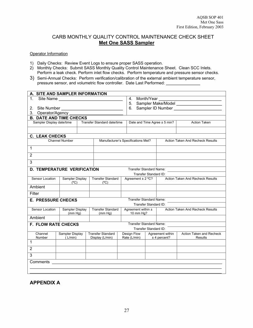
CARB MONTHLY QUALITY CONTROL MAINTENANCE CHECK SHEETMet One SASS Sampler
Operator Information
1) Daily Checks: Review Event Logs to ensure proper SASS operation.2) Monthly Checks: Submit SASS Monthly Quality Control Maintenance Sheet. Clean SCC Inlets.
Perform a leak check. Perform inlet flow checks. Perform temperature and pressure sensor checks.3) Semi-Annual Checks: Perform verification/calibration of the external ambient temperature sensor,
pressure sensor, and volumetric flow controller. Date Last Performed:
A. SITE AND SAMPLER INFORMATION1. Site Name
2. Site Number 3. Operator/Agency
4. Month/Year 5. Sampler Make/Model 6. Sampler ID Number
B. DATE AND TIME CHECKSSampler Display date/time Transfer Standard date/time Date and Time Agree ± 5 min? Action Taken
C. LEAK CHECKSChannel Number Manufacturer’s Specifications Met? Action Taken And Recheck Results
1
2
3Transfer Standard Name:D. TEMPERATURE VERIFICATION
Transfer Standard ID:Sensor Location Sampler Display
(ºC)Transfer Standard
(ºC)Agreement ± 2 ºC? Action Taken And Recheck Results
AmbientFilter
Transfer Standard Name:E. PRESSURE CHECKS Transfer Standard ID:
Sensor Location Sampler Display(mm Hg)
Transfer Standard(mm Hg)
Agreement within ± 10 mm Hg?
Action Taken And Recheck Results
AmbientTransfer Standard Name:F. FLOW RATE CHECKS
Transfer Standard ID:ChannelNumber
Sampler Display( L/min)
Transfer StandardDisplay (L/min)
Design FlowRate (L/min)
Agreement within± 4 percent?
Action Taken and RecheckResults
123Comments
APPENDIX A
AQSB SOP 401Met One Sass
First Edition, February 2003
28
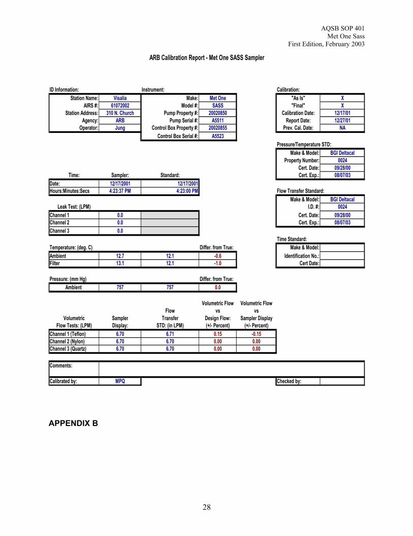
APPENDIX B
ID Information: Instrument: Calibration:
Station Name: Visalia Make: Met One "As Is" XAIRS #: 61072002 Model #: SASS "Final" X
Station Address: 310 N. Church Pump Property #: 20020850 Calibration Date: 12/17/01Agency: ARB Pump Serial #: A5511 Report Date: 12/27/01
Operator: Jung Control Box Property #: 20020855 Prev. Cal. Date: NAControl Box Serial #: A5523
Pressure/Temperature STD:Make & Model: BGI Deltacal
Property Number: 0024Cert. Date: 09/28/00
Time: Sampler: Standard: Cert. Exp.: 08/07/03Date: 12/17/2001 12/17/2001Hours:Minutes:Secs 4:23:37 PM 4:23:00 PM Flow Transfer Standard:
Make & Model: BGI DeltacalLeak Test: (LPM) I.D. #: 0024
Channel 1 0.0 Cert. Date: 09/28/00Channel 2 0.0 Cert. Exp.: 08/07/03Channel 3 0.0
Time Standard:Temperature: (deg. C) Differ. from True: Make & Model:Ambient 12.7 12.1 -0.6 Identification No.:Filter 13.1 12.1 -1.0 Cert Date:
Pressure: (mm Hg) Differ. from True:Ambient 757 757 0.0
Volumetric Flow Volumetric FlowFlow vs vs
Volumetric Sampler Transfer Design Flow: Sampler DisplayFlow Tests: (LPM) Display: STD: (in LPM) (+/- Percent) (+/- Percent)
Channel 1 (Teflon) 6.70 6.71 0.15 -0.15Channel 2 (Nylon) 6.70 6.70 0.00 0.00Channel 3 (Quartz) 6.70 6.70 0.00 0.00
Comments:
Calibrated by: MPQ Checked by:
ARB Calibration Report - Met One SASS Sampler
AQSB SOP 401Met One Sass
First Edition, February 2003
29
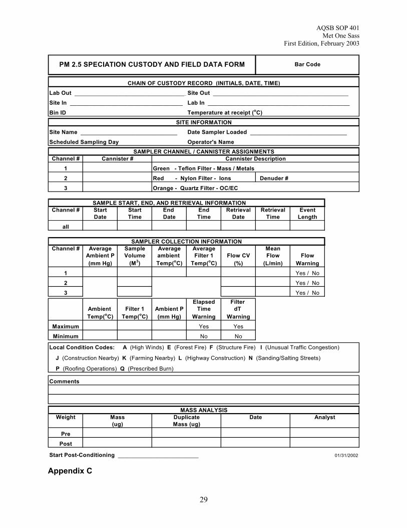
Lab Out ___________________________________Site Out __________________________________________
Site In ___________________________________ Lab In ____________________________________________
Bin ID Temperature at receipt (oC)
Site Name ______________________________ Date Sampler Loaded ______________________________
Scheduled Sampling Day Operator's Name
Channel #1 Green - Teflon Filter - Mass / Metals2 Red - Nylon Filter - Ions Denuder #3 Orange - Quartz Filter - OC/EC
Channel # Start Start End End Retrieval Retrieval EventDate Time Date Time Date Time Length
all
Channel # Average Sample Average Average MeanAmbient P Volume ambient Filter 1 Flow CV Flow Flow(mm Hg) (M3) Temp(oC) Temp(oC) (%) (L/min) Warning
1 Yes / No
2 Yes / No
3 Yes / NoElapsed Filter
Ambient Filter 1 Ambient P Time dT Temp(oC) Temp(oC) (mm Hg) Warning Warning
Maximum Yes Yes
Minimum No No
Local Condition Codes: A (High Winds) E (Forest Fire) F (Structure Fire) I (Unusual Traffic Congestion)
J (Construction Nearby) K (Farming Nearby) L (Highway Construction) N (Sanding/Salting Streets)
P (Roofing Operations) Q (Prescribed Burn)
Comments
Weight
PrePost
Start Post-Conditioning _________________________ 01/31/2002
Date AnalystMass(ug)
DuplicateMass (ug)
MASS ANALYSIS
SAMPLER CHANNEL / CANNISTER ASSIGNMENTS
SAMPLE START, END, AND RETRIEVAL INFORMATION
Cannister # Cannister Description
SAMPLER COLLECTION INFORMATION
PM 2.5 SPECIATION CUSTODY AND FIELD DATA FORM Bar Code
CHAIN OF CUSTODY RECORD (INITIALS, DATE, TIME)
SITE INFORMATION
Appendix C