
Air jet and Rapier loom
77
A PRESENTATION ON MODERN AIRJET & RAPIER LOOM Md. Azmir Latif MSc. in Textile Engineer
-
Upload
mdazmir-latif-beg -
Category
Engineering
-
view
840 -
download
94
Transcript of Air jet and Rapier loom
A PRESENTATION ON
MODERN AIRJET & RAPIER LOOM
Md. Azmir LatifMSc. in Textile Engineer
A MODERN RAPIER LOOM
Keyword: General specification, yarn passages, basic motions, shedding, picking, beat up, let off, take up, warp stop motion, others auxiliary motion
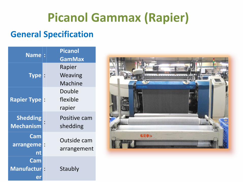
Picanol Gammax (Rapier)General Specification
Name :Picanol
GamMax
Type :
Rapier
Weaving
Machine
Rapier Type :
Double
flexible
rapier
Shedding
Mechanism:
Positive cam
shedding
Cam
arrangeme
nt
:Outside cam
arrangement
Cam
Manufactur
er
: Staubly
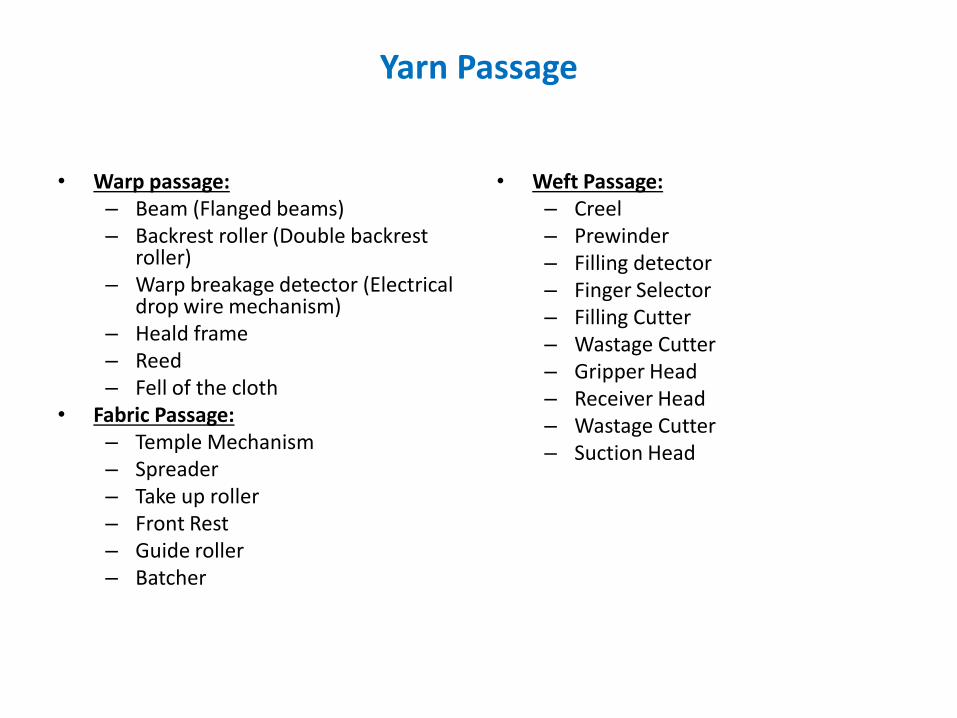
Yarn Passage
• Warp passage:– Beam (Flanged beams)– Backrest roller (Double backrest
roller)– Warp breakage detector (Electrical
drop wire mechanism)– Heald frame– Reed– Fell of the cloth
• Fabric Passage:– Temple Mechanism– Spreader– Take up roller– Front Rest– Guide roller– Batcher
• Weft Passage:– Creel– Prewinder– Filling detector– Finger Selector– Filling Cutter– Wastage Cutter– Gripper Head– Receiver Head– Wastage Cutter– Suction Head
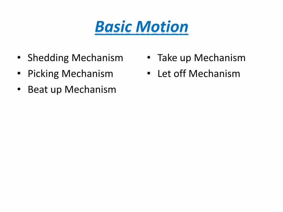
Basic Motion
• Shedding Mechanism
• Picking Mechanism
• Beat up Mechanism
• Take up Mechanism
• Let off Mechanism

shedding mechanism
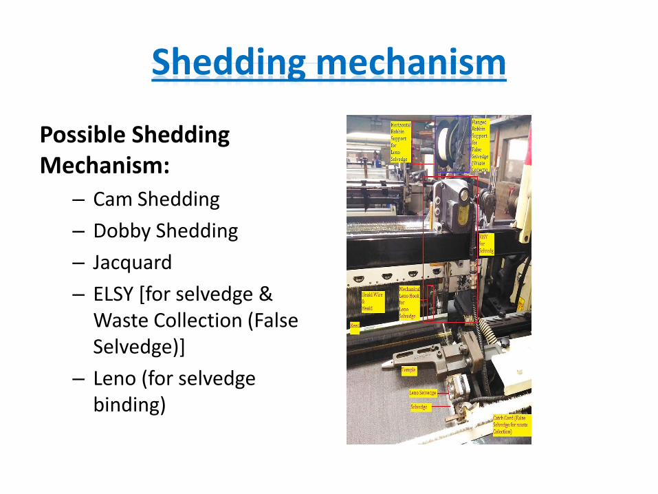
Shedding mechanism
Possible Shedding Mechanism:
– Cam Shedding
– Dobby Shedding
– Jacquard
– ELSY [for selvedge & Waste Collection (False Selvedge)]
– Leno (for selvedge binding)
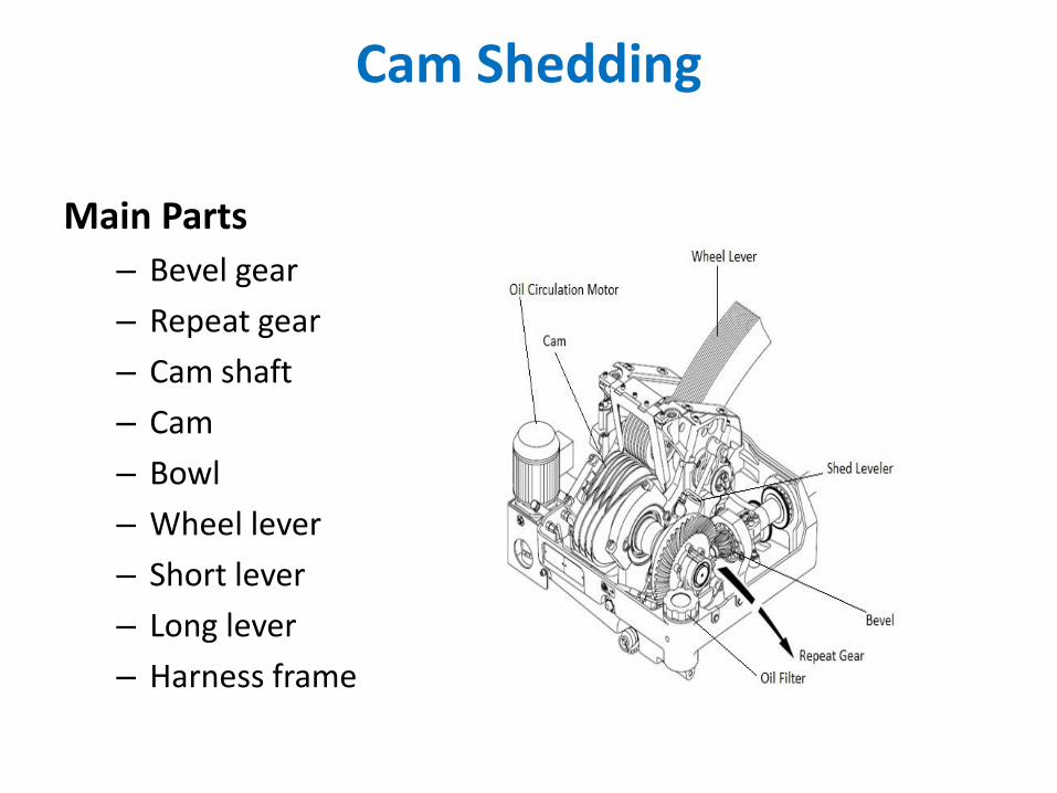
Cam Shedding
Main Parts
– Bevel gear
– Repeat gear
– Cam shaft
– Cam
– Bowl
– Wheel lever
– Short lever
– Long lever
– Harness frame
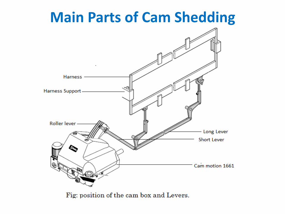
Main Parts of Cam Shedding
Cam
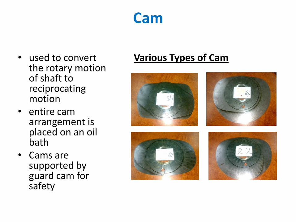
• used to convert the rotary motion of shaft to reciprocating motion
• entire cam arrangement is placed on an oil bath
• Cams are supported by guard cam for safety
Various Types of Cam
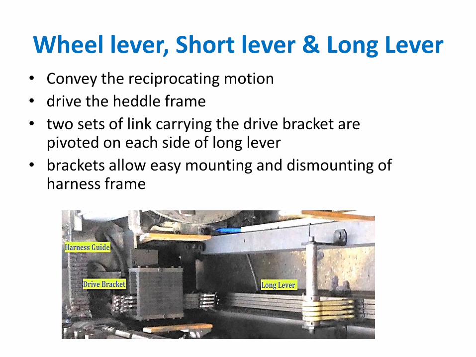
Wheel lever, Short lever & Long Lever• Convey the reciprocating motion
• drive the heddle frame
• two sets of link carrying the drive bracket are pivoted on each side of long lever
• brackets allow easy mounting and dismounting of harness frame
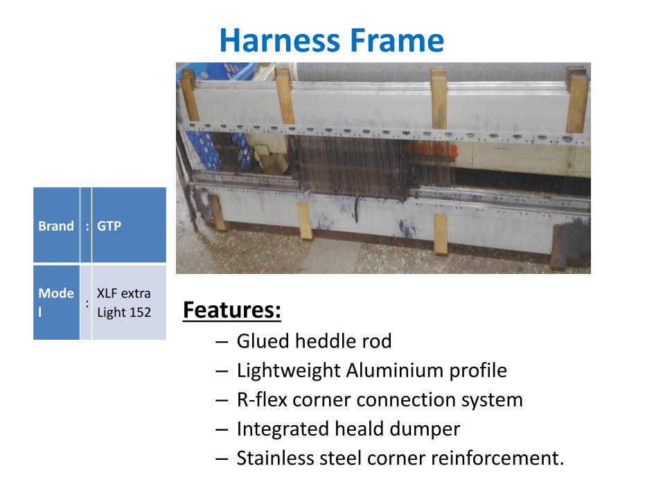
Harness Frame
Features:– Glued heddle rod
– Lightweight Aluminium profile
– R-flex corner connection system
– Integrated heald dumper
– Stainless steel corner reinforcement.
Brand : GTP
Mode
l:
XLF extra
Light 152
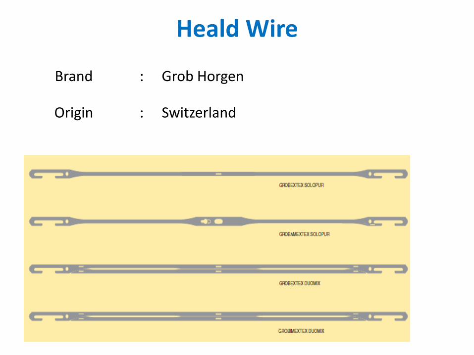
Heald Wire
Brand : Grob Horgen
Origin : Switzerland
Cam Shedding Mechanism
• According to pattern cams are added andadjusted to their respective position
• As the camshaft rotates cams also rotate• When the bowl is pressed, the wheel lever swing
upward• Via long lever, harness frame is pushed upward to
its upper position• Again after cam nose has passed the bowl, the
harness is pulled to its bottom position• It is a positive shedding mechanism
ELSY
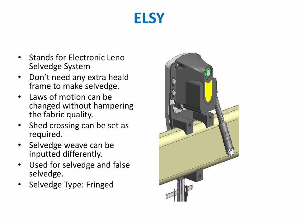
• Stands for Electronic Leno Selvedge System
• Don’t need any extra healdframe to make selvedge.
• Laws of motion can be changed without hampering the fabric quality.
• Shed crossing can be set as required.
• Selvedge weave can be inputted differently.
• Used for selvedge and false selvedge.
• Selvedge Type: Fringed
Mechanical Leno
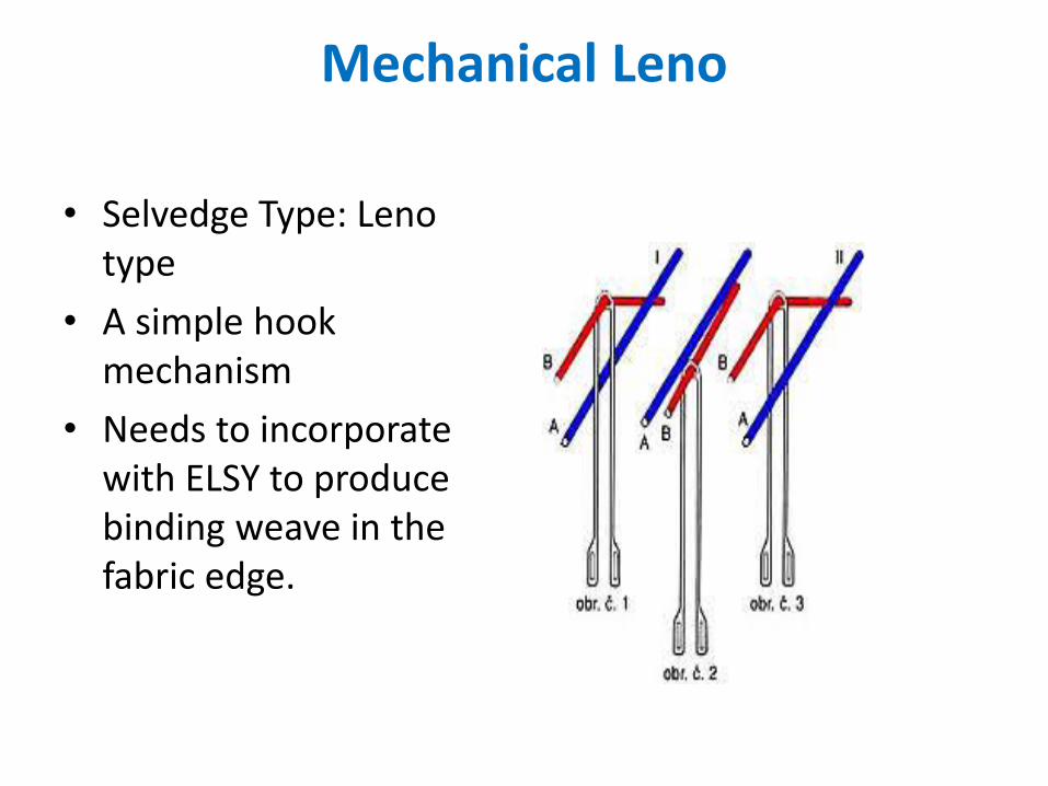
• Selvedge Type: Leno type
• A simple hook mechanism
• Needs to incorporate with ELSY to produce binding weave in the fabric edge.

picking mechanism
Picking Mechanism
General features– Flexible rapier
– Double (2 rapiers)
– Sprocket type wheel drive
– 2 heads (gripper & receiver)
– Side housing, fixed (unmovable)
• Main parts
• Creel
• Prewinder
• Filling detector
• Filling Presenter
• Filling Cutter
• Gripper
• Receiver
• Suction head
• Wastage cutters
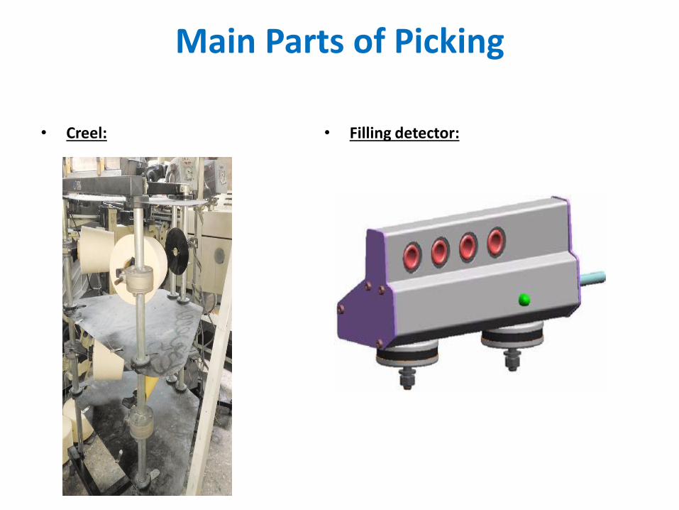
Main Parts of Picking
• Creel: • Filling detector:
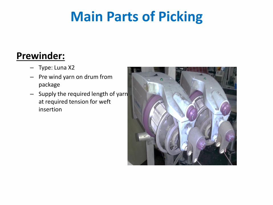
Main Parts of Picking
Prewinder:– Type: Luna X2
– Pre wind yarn on drum from package
– Supply the required length of yarn at required tension for weft insertion
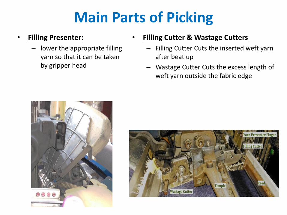
Main Parts of Picking• Filling Presenter:
– lower the appropriate filling yarn so that it can be taken by gripper head
• Filling Cutter & Wastage Cutters
– Filling Cutter Cuts the inserted weft yarn after beat up
– Wastage Cutter Cuts the excess length of weft yarn outside the fabric edge
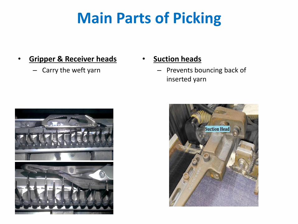
Main Parts of Picking
• Gripper & Receiver heads
– Carry the weft yarn
• Suction heads
– Prevents bouncing back of inserted yarn
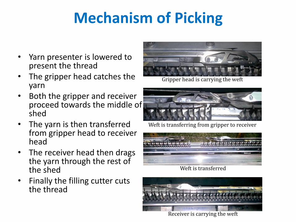
Mechanism of Picking
• Yarn presenter is lowered to present the thread
• The gripper head catches the yarn
• Both the gripper and receiver proceed towards the middle of shed
• The yarn is then transferred from gripper head to receiver head
• The receiver head then drags the yarn through the rest of the shed
• Finally the filling cutter cuts the thread
Gripper head is carrying the weft
Weft is transferring from gripper to receiver
Weft is transferred
Receiver is carrying the weft
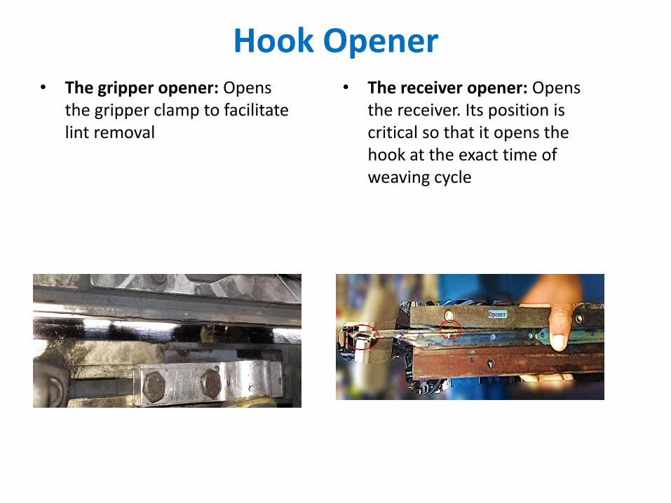
Hook Opener• The gripper opener: Opens
the gripper clamp to facilitate lint removal
• The receiver opener: Opens the receiver. Its position is critical so that it opens the hook at the exact time of weaving cycle
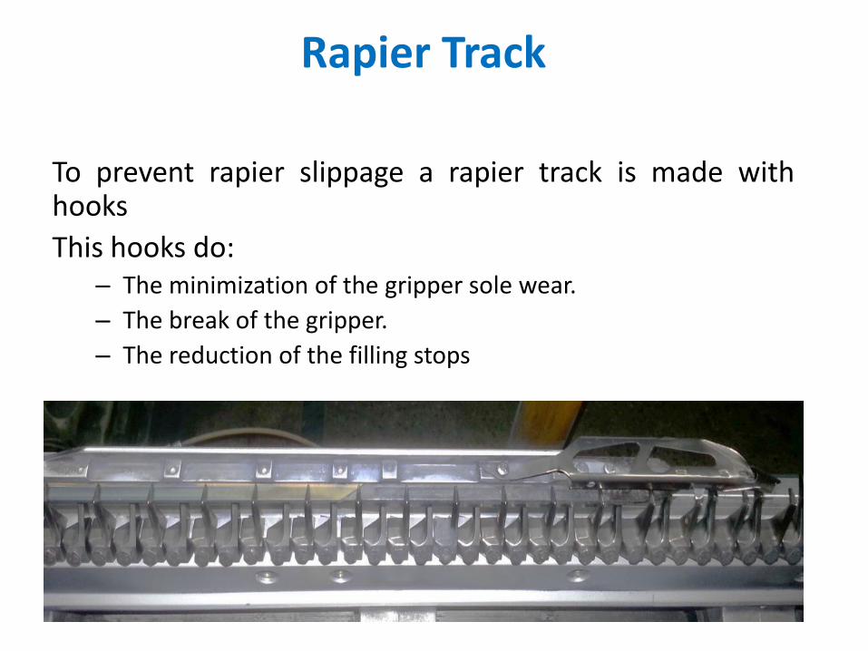
Rapier Track
To prevent rapier slippage a rapier track is made withhooks
This hooks do:– The minimization of the gripper sole wear.
– The break of the gripper.
– The reduction of the filling stops
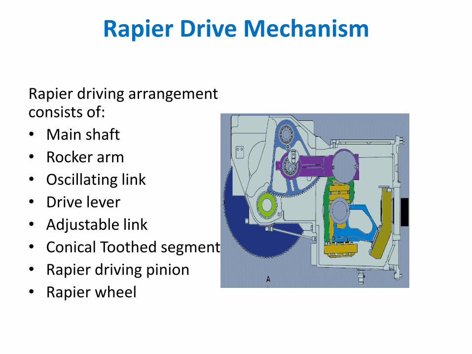
Rapier Drive Mechanism
Rapier driving arrangement consists of:
• Main shaft
• Rocker arm
• Oscillating link
• Drive lever
• Adjustable link
• Conical Toothed segment
• Rapier driving pinion
• Rapier wheel
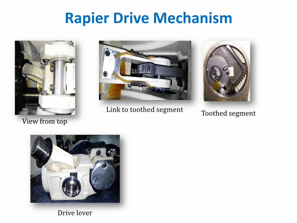
Rapier Drive Mechanism
View from top
Drive lever
Toothed segmentLink to toothed segment

Beat up mechanism
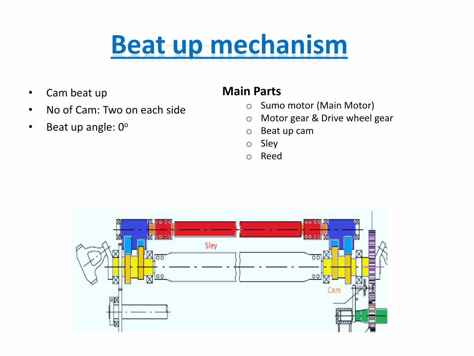
Beat up mechanism
• Cam beat up
• No of Cam: Two on each side
• Beat up angle: 0o
Main Partso Sumo motor (Main Motor)o Motor gear & Drive wheel gearo Beat up camo Sleyo Reed
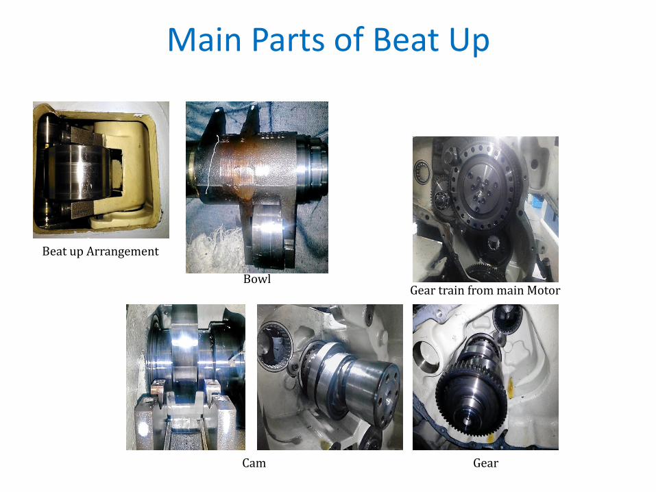
Main Parts of Beat Up
Beat up Arrangement
Bowl
Cam Gear
Gear train from main Motor
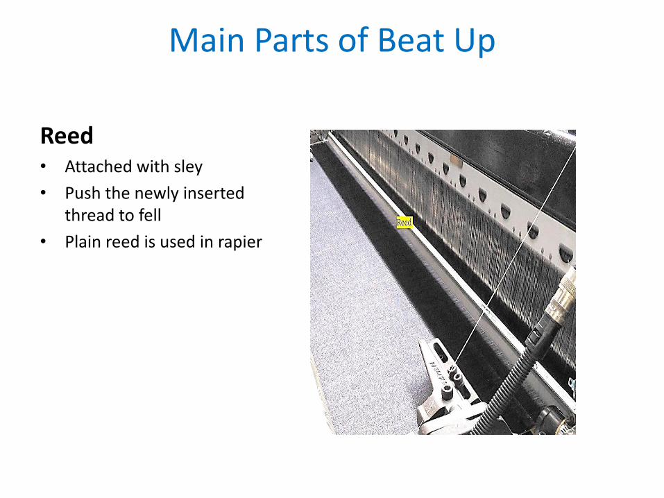
Main Parts of Beat Up
Reed• Attached with sley
• Push the newly inserted thread to fell
• Plain reed is used in rapier
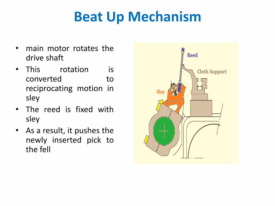
Beat Up Mechanism
• main motor rotates thedrive shaft
• This rotation isconverted toreciprocating motion insley
• The reed is fixed withsley
• As a result, it pushes thenewly inserted pick tothe fell

Let off mechanism
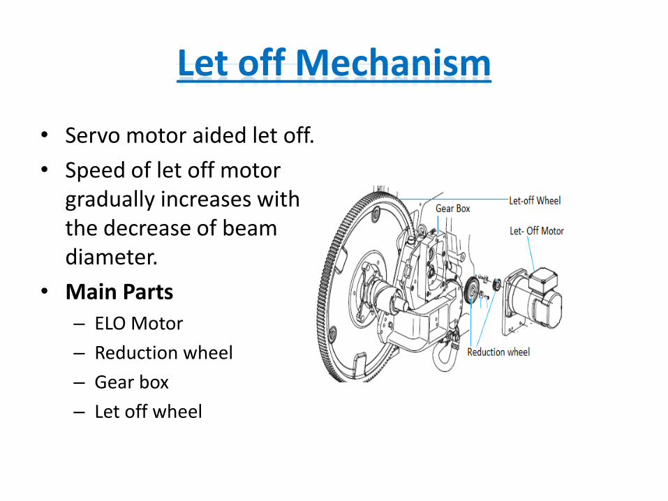
Let off Mechanism
• Servo motor aided let off.
• Speed of let off motor gradually increases with the decrease of beam diameter.
• Main Parts
– ELO Motor
– Reduction wheel
– Gear box
– Let off wheel
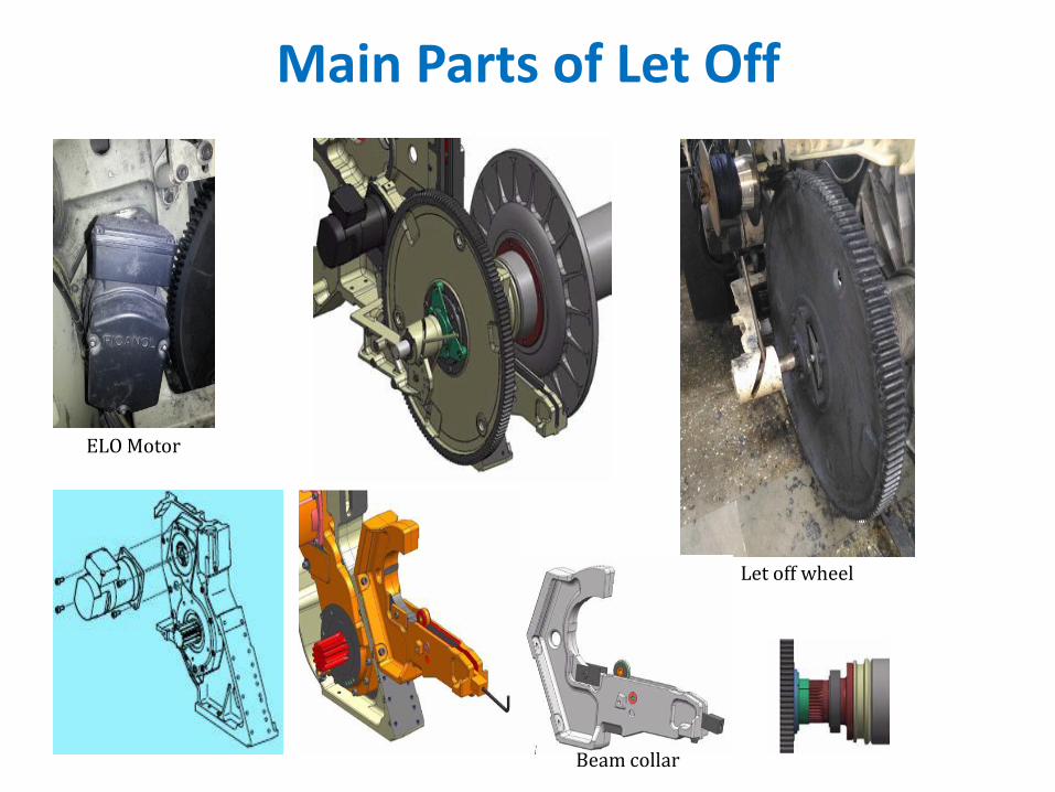
Main Parts of Let Off
ELO Motor
Let off wheel
Beam collar

take up mechanism
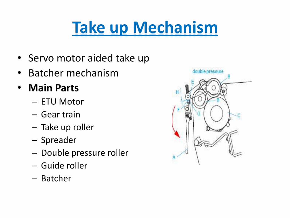
Take up Mechanism
• Servo motor aided take up
• Batcher mechanism
• Main Parts– ETU Motor
– Gear train
– Take up roller
– Spreader
– Double pressure roller
– Guide roller
– Batcher
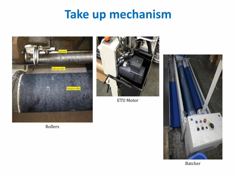
Take up mechanism
Rollers
ETU Motor
Batcher
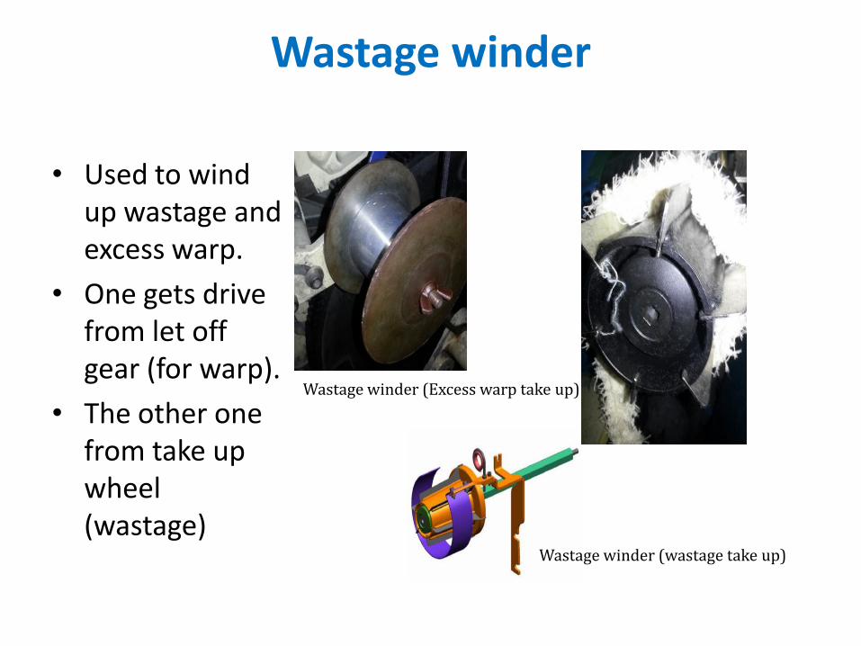
Wastage winder
• Used to wind up wastage and excess warp.
• One gets drive from let off gear (for warp).
• The other one from take up wheel (wastage)
Wastage winder (wastage take up)
Wastage winder (Excess warp take up)

others motion
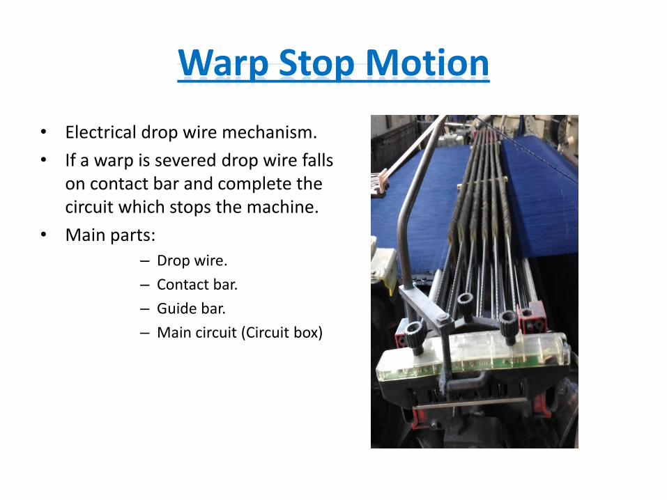
Warp Stop Motion
• Electrical drop wire mechanism.
• If a warp is severed drop wire falls on contact bar and complete the circuit which stops the machine.
• Main parts:
– Drop wire.
– Contact bar.
– Guide bar.
– Main circuit (Circuit box)
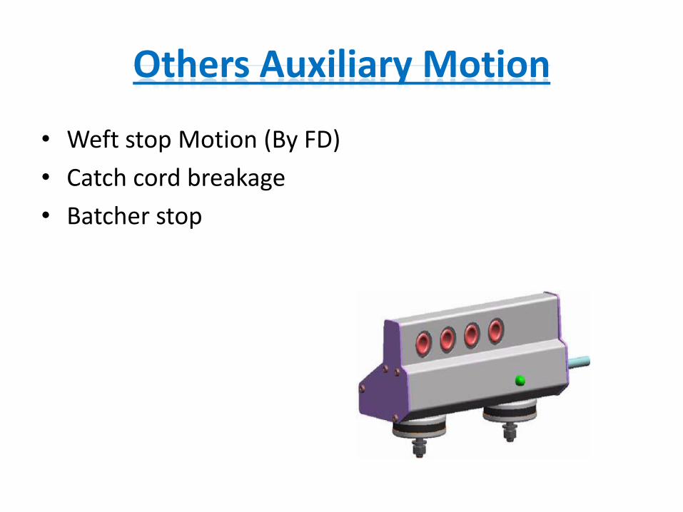
Others Auxiliary Motion
• Weft stop Motion (By FD)
• Catch cord breakage
• Batcher stop

A MODERN AIRJET LOOM
Keyword: General features, main parts, motions, shedding, picking, beat up, let off, take up, warp stop motion, weft stop motion, others stop motion
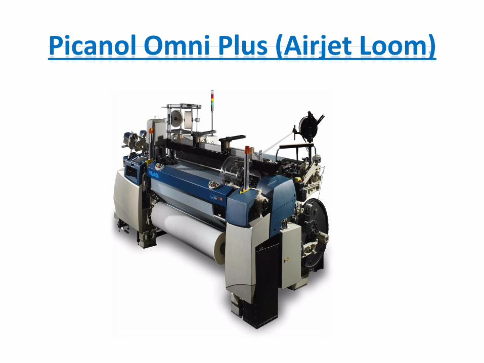
Picanol Omni Plus (Airjet Loom)
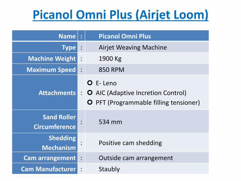
Picanol Omni Plus (Airjet Loom)
Name : Picanol Omni Plus
Type : Airjet Weaving Machine
Machine Weight : 1900 Kg
Maximum Speed : 850 RPM
Attachments :
E- Leno
AIC (Adaptive Incretion Control)
PFT (Programmable filling tensioner)
Sand Roller
Circumference: 534 mm
Shedding
Mechanism: Positive cam shedding
Cam arrangement : Outside cam arrangement
Cam Manufacturer : Staubly
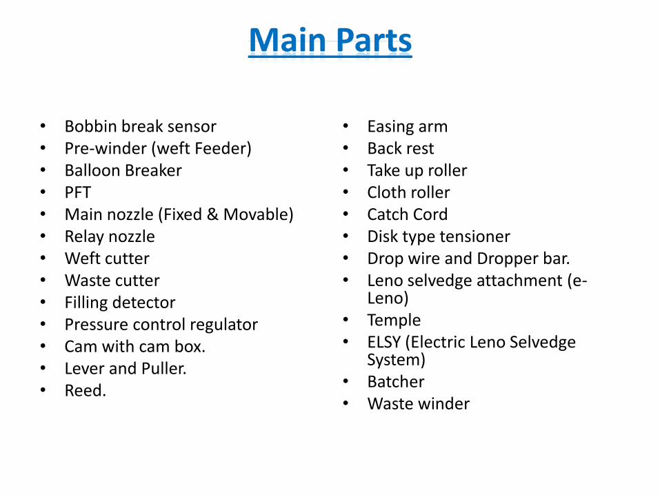
Main Parts
• Bobbin break sensor• Pre-winder (weft Feeder)• Balloon Breaker• PFT• Main nozzle (Fixed & Movable)• Relay nozzle• Weft cutter• Waste cutter• Filling detector • Pressure control regulator• Cam with cam box.• Lever and Puller.• Reed.
• Easing arm• Back rest• Take up roller• Cloth roller• Catch Cord• Disk type tensioner• Drop wire and Dropper bar.• Leno selvedge attachment (e-
Leno)• Temple• ELSY (Electric Leno Selvedge
System)• Batcher• Waste winder
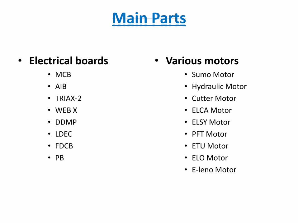
Main Parts
• Electrical boards• MCB
• AIB
• TRIAX-2
• WEB X
• DDMP
• LDEC
• FDCB
• PB
• Various motors• Sumo Motor
• Hydraulic Motor
• Cutter Motor
• ELCA Motor
• ELSY Motor
• PFT Motor
• ETU Motor
• ELO Motor
• E-leno Motor
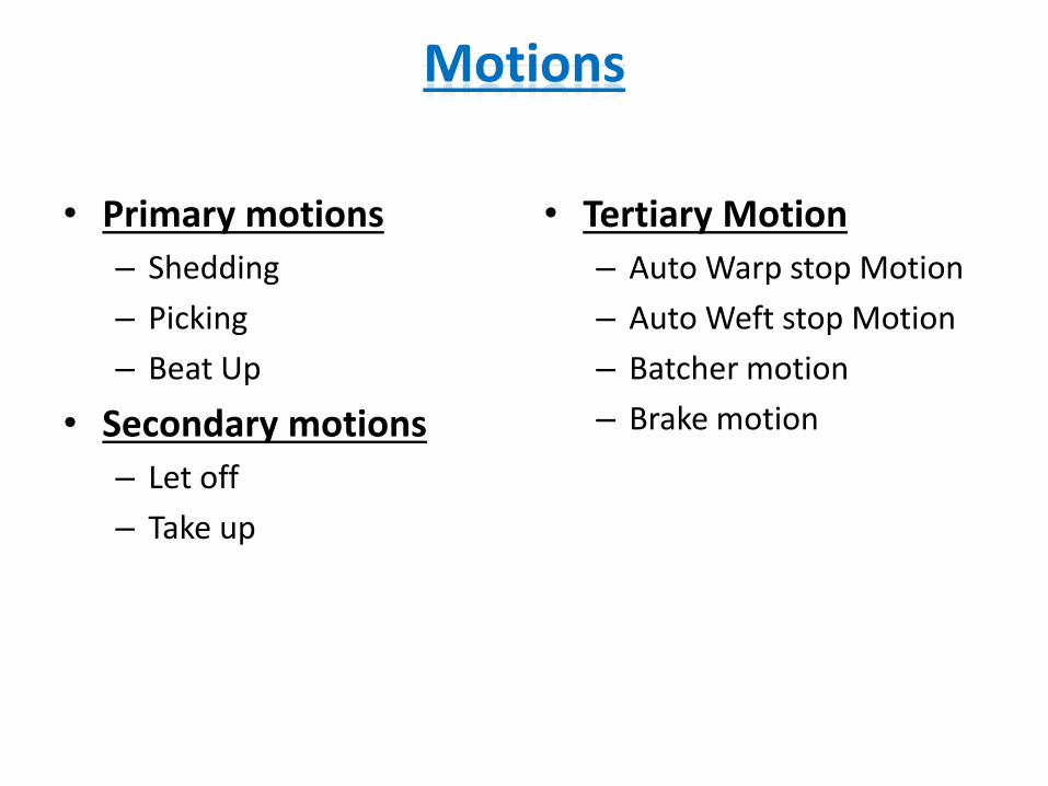
Motions
• Primary motions
– Shedding
– Picking
– Beat Up
• Secondary motions
– Let off
– Take up
• Tertiary Motion
– Auto Warp stop Motion
– Auto Weft stop Motion
– Batcher motion
– Brake motion

Shedding mechanism
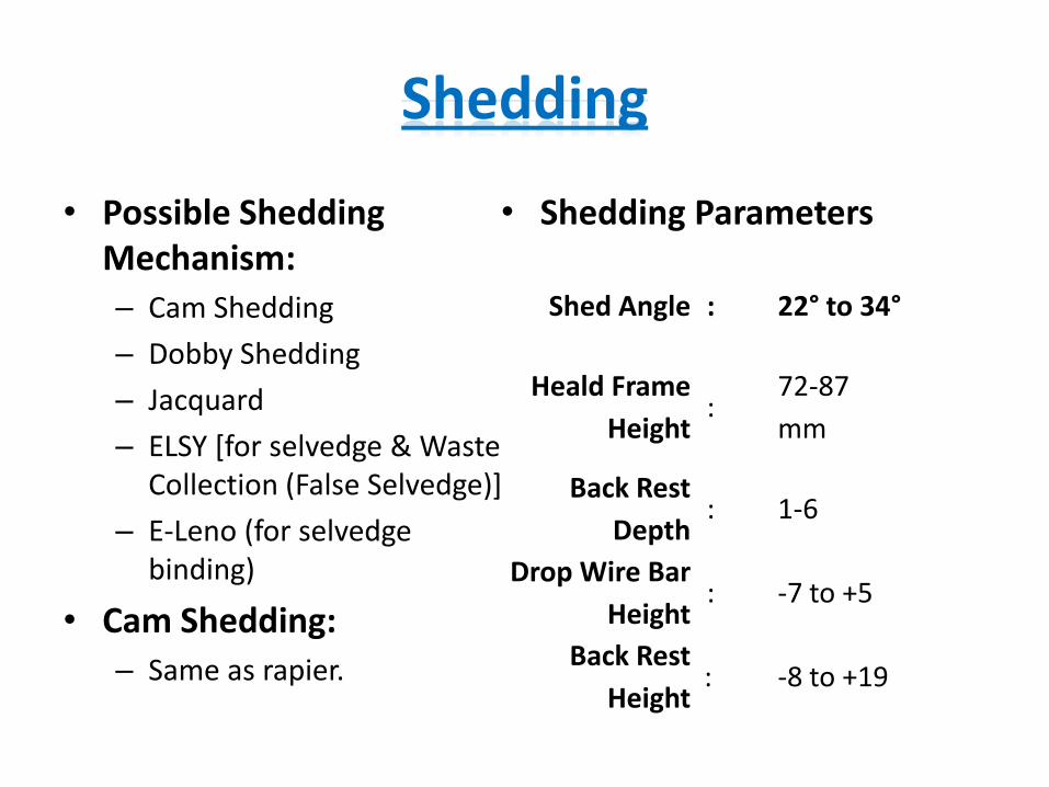
Shedding
• Possible Shedding Mechanism:
– Cam Shedding
– Dobby Shedding
– Jacquard
– ELSY [for selvedge & Waste Collection (False Selvedge)]
– E-Leno (for selvedge binding)
• Cam Shedding:
– Same as rapier.
• Shedding Parameters
Shed Angle : 22° to 34°
Heald Frame
Height:
72-87
mm
Back Rest
Depth: 1-6
Drop Wire Bar
Height: -7 to +5
Back Rest
Height: -8 to +19
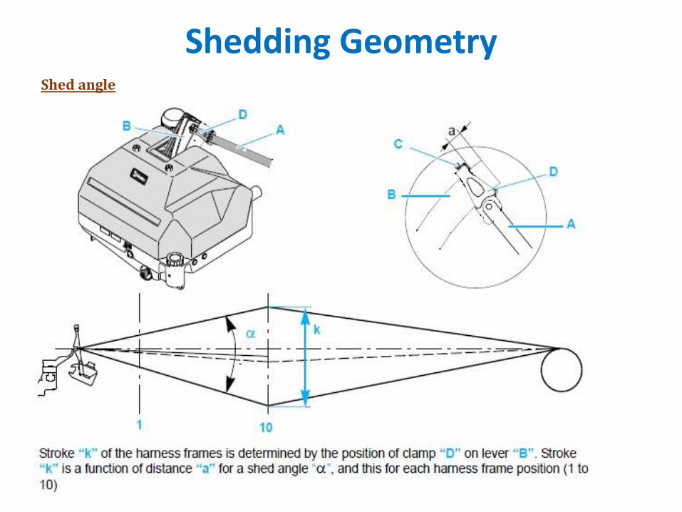
Shedding GeometryShed angle
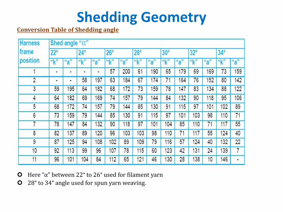
Shedding GeometryConversion Table of Shedding angle
Here “α” between 22° to 26° used for filament yarn
28° to 34° angle used for spun yarn weaving.
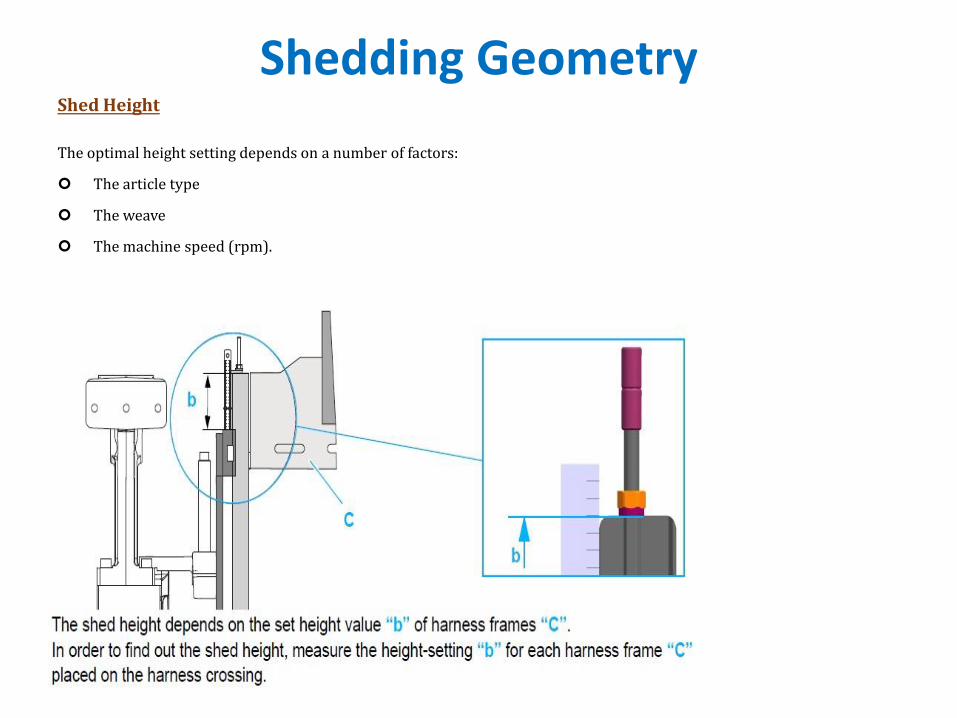
Shedding GeometryShed Height
The optimal height setting depends on a number of factors:
The article type
The weave
The machine speed (rpm).
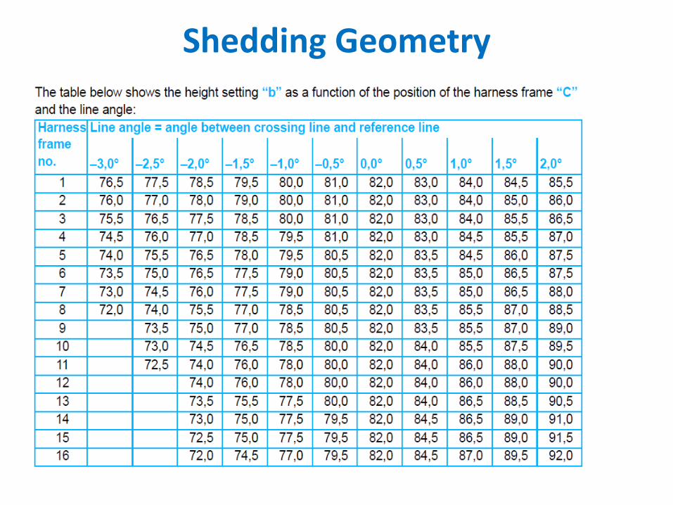
Shedding Geometry
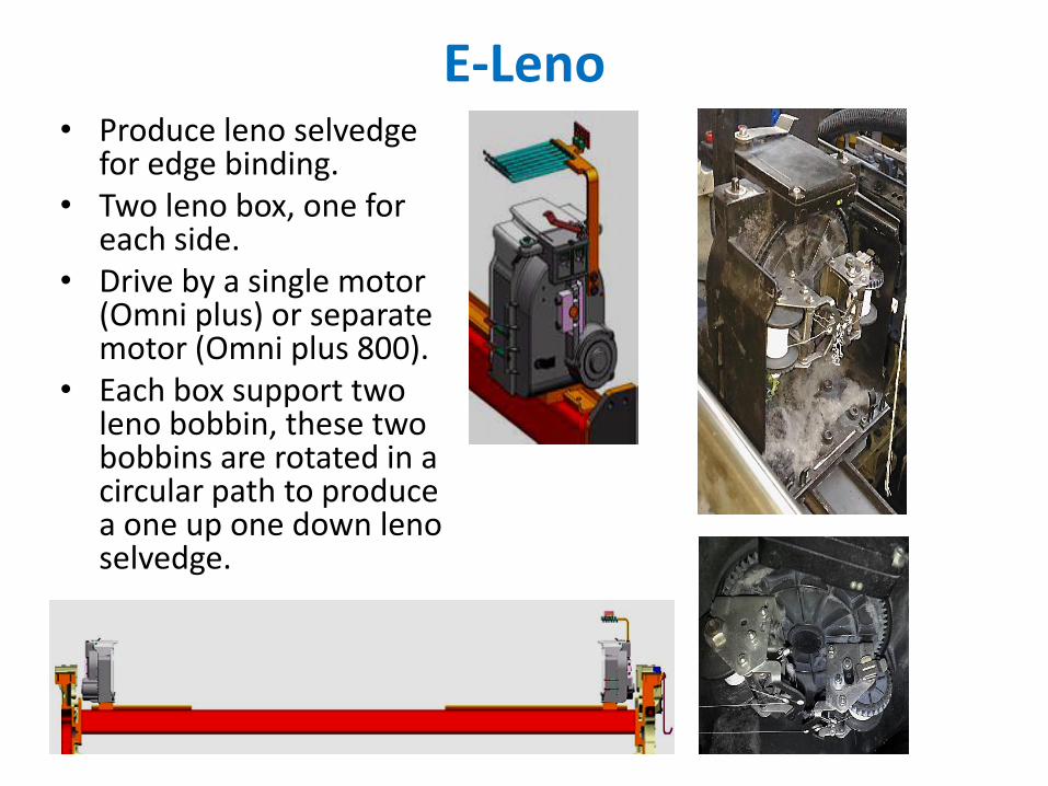
E-Leno• Produce leno selvedge
for edge binding.• Two leno box, one for
each side.• Drive by a single motor
(Omni plus) or separate motor (Omni plus 800).
• Each box support two leno bobbin, these two bobbins are rotated in a circular path to produce a one up one down leno selvedge.

picking mechanism
Picking
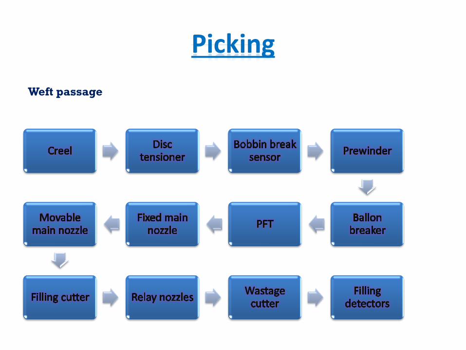
Weft passage
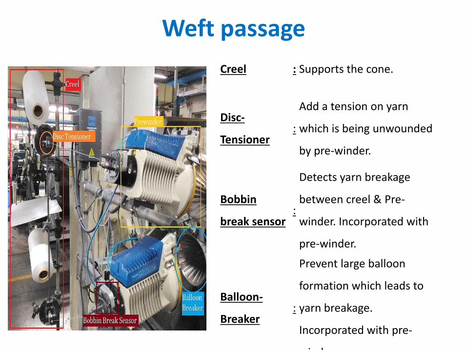
Weft passage
Creel : Supports the cone.
Disc-
Tensioner:
Add a tension on yarn
which is being unwounded
by pre-winder.
Bobbin
break sensor:
Detects yarn breakage
between creel & Pre-
winder. Incorporated with
pre-winder.
Balloon-
Breaker :
Prevent large balloon
formation which leads to
yarn breakage.
Incorporated with pre-
winder.
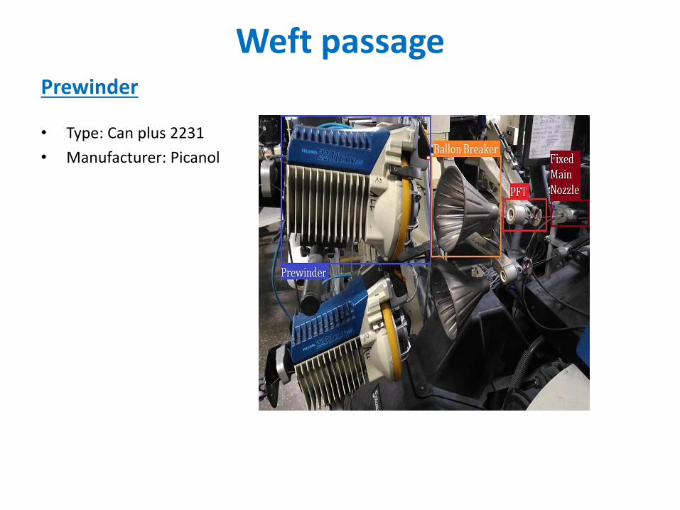
Weft passage
• Type: Can plus 2231
• Manufacturer: Picanol
Prewinder
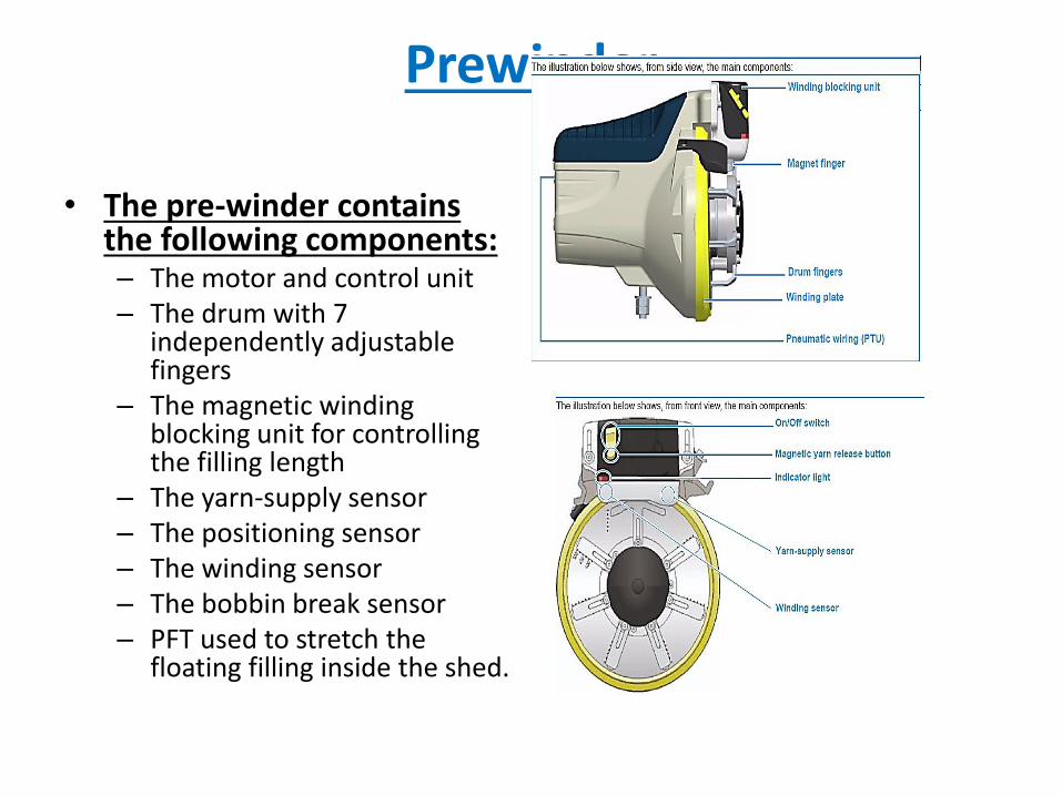
Prewinder
• The pre-winder contains the following components:– The motor and control unit– The drum with 7
independently adjustable fingers
– The magnetic winding blocking unit for controlling the filling length
– The yarn-supply sensor– The positioning sensor– The winding sensor– The bobbin break sensor– PFT used to stretch the
floating filling inside the shed.
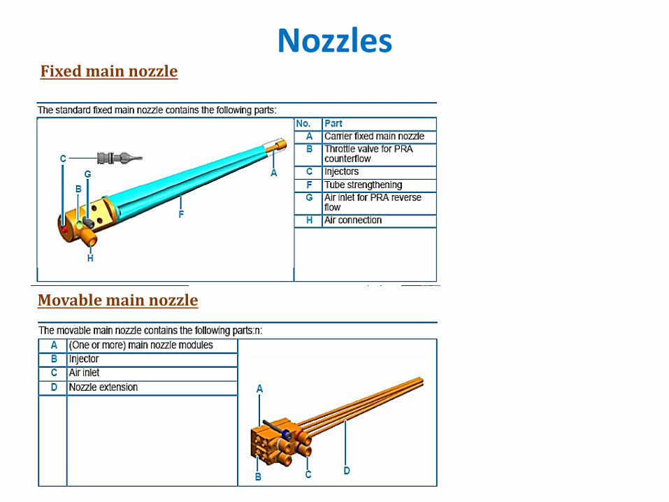
NozzlesFixed main nozzle
Movable main nozzle
Nozzles
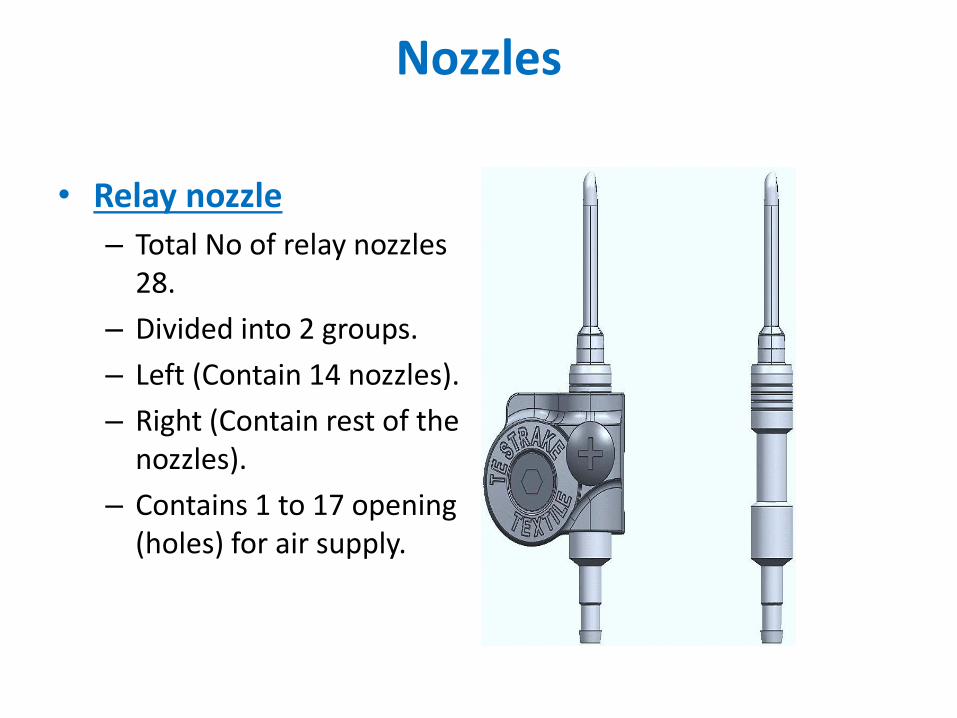
• Relay nozzle
– Total No of relay nozzles 28.
– Divided into 2 groups.
– Left (Contain 14 nozzles).
– Right (Contain rest of the nozzles).
– Contains 1 to 17 opening (holes) for air supply.
Nozzles
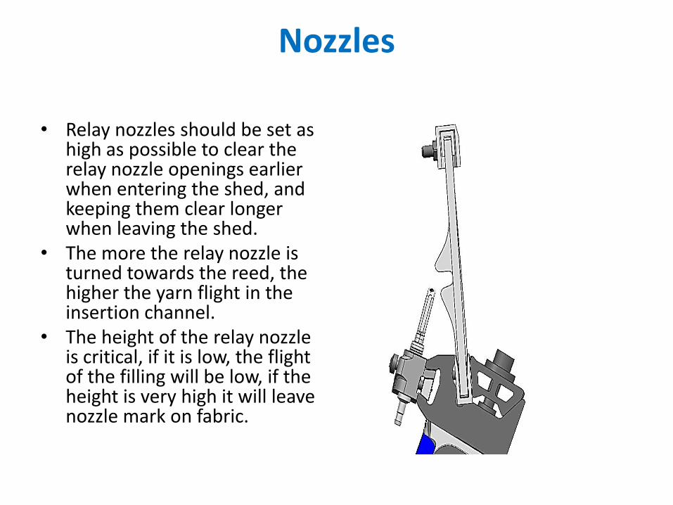
• Relay nozzles should be set as high as possible to clear the relay nozzle openings earlier when entering the shed, and keeping them clear longer when leaving the shed.
• The more the relay nozzle is turned towards the reed, the higher the yarn flight in the insertion channel.
• The height of the relay nozzle is critical, if it is low, the flight of the filling will be low, if the height is very high it will leave nozzle mark on fabric.
Air Supply accessories
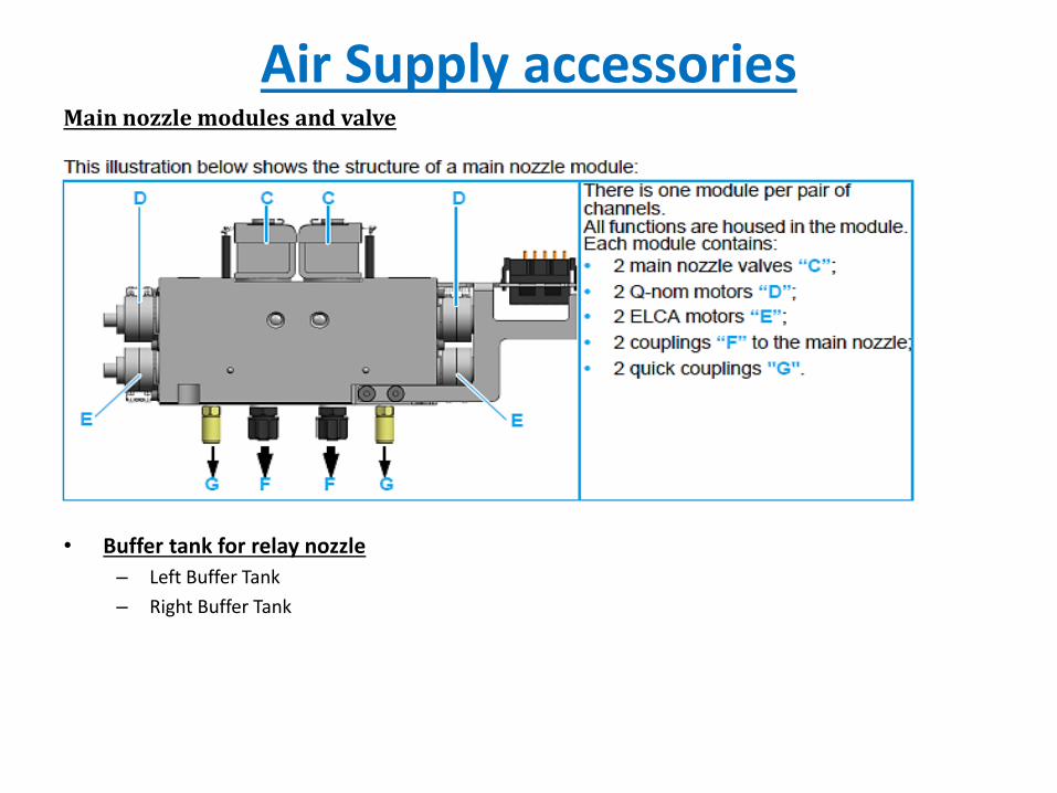
• Buffer tank for relay nozzle
– Left Buffer Tank
– Right Buffer Tank
Main nozzle modules and valve
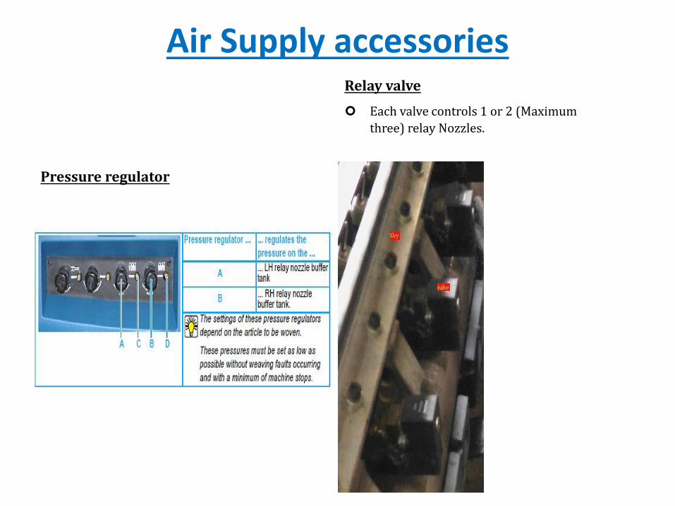
Air Supply accessoriesRelay valve
Each valve controls 1 or 2 (Maximum
three) relay Nozzles.
Pressure regulator
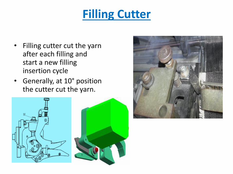
Filling Cutter
• Filling cutter cut the yarn after each filling and start a new filling insertion cycle
• Generally, at 10° position the cutter cut the yarn.
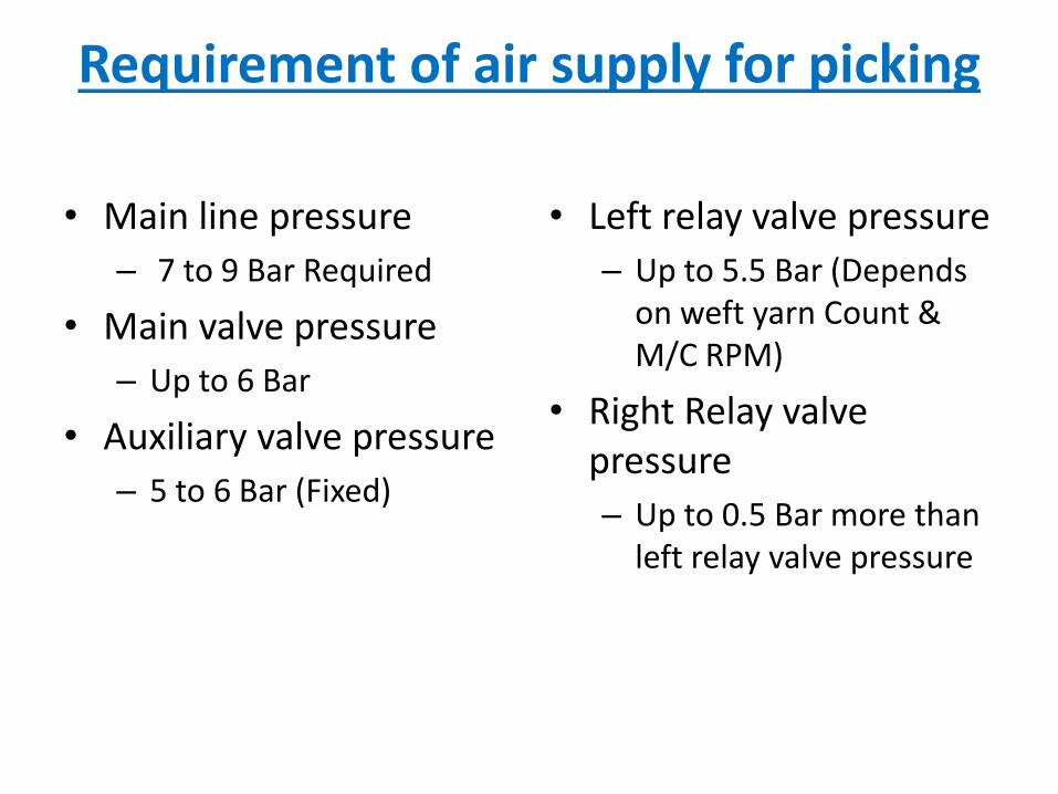
Requirement of air supply for picking
• Main line pressure
– 7 to 9 Bar Required
• Main valve pressure
– Up to 6 Bar
• Auxiliary valve pressure
– 5 to 6 Bar (Fixed)
• Left relay valve pressure
– Up to 5.5 Bar (Depends on weft yarn Count & M/C RPM)
• Right Relay valve pressure
– Up to 0.5 Bar more than left relay valve pressure

beat up mechanism
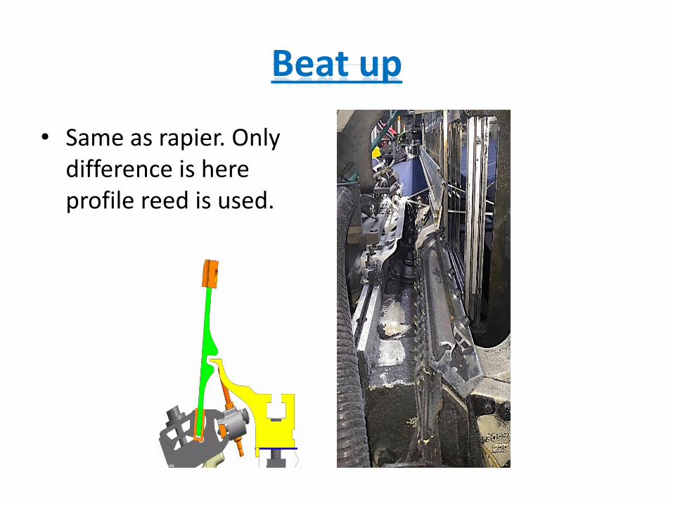
Beat up
• Same as rapier. Only difference is here profile reed is used.
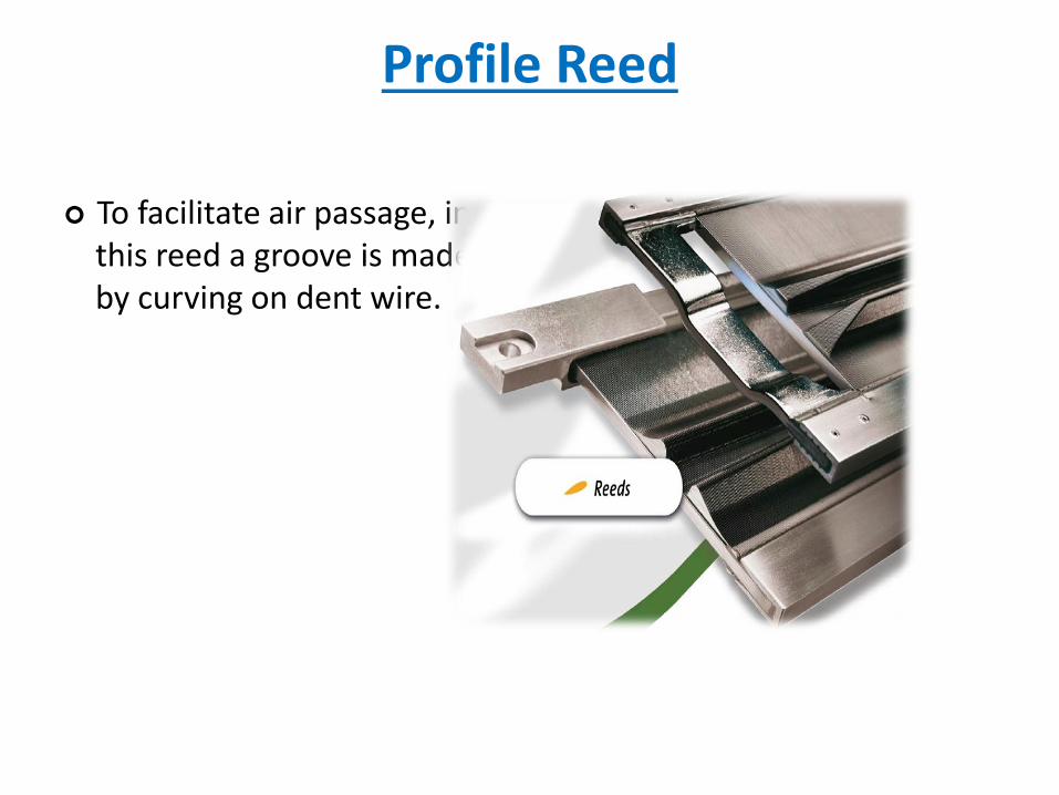
Profile Reed
To facilitate air passage, in this reed a groove is made by curving on dent wire.
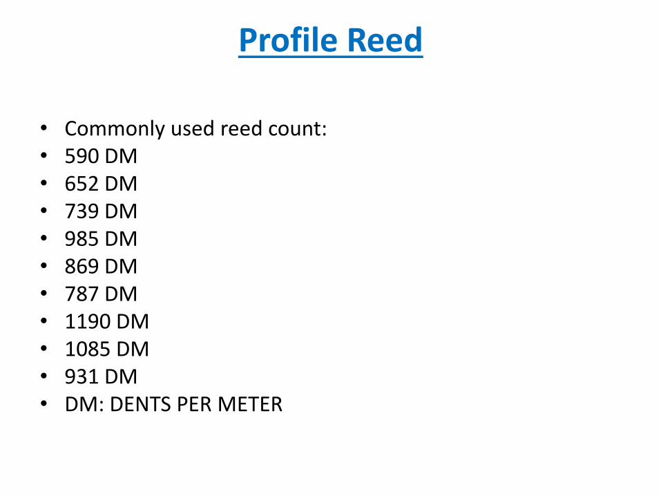
Profile Reed
• Commonly used reed count:• 590 DM• 652 DM• 739 DM• 985 DM• 869 DM• 787 DM• 1190 DM• 1085 DM• 931 DM• DM: DENTS PER METER

others motion

Same as rapier.
Same as rapier.
Same as rapier.
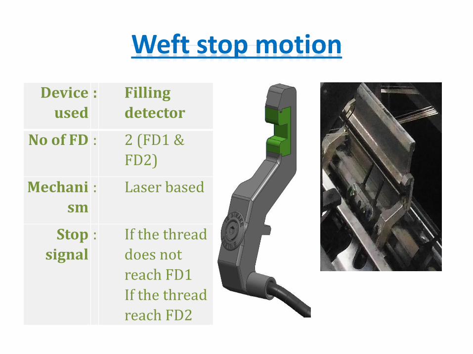
Weft stop motion
Device
used
: Filling
detector
No of FD : 2 (FD1 &
FD2)
Mechani
sm
: Laser based
Stop
signal
: If the thread
does not
reach FD1
If the thread
reach FD2
Weft stop motion
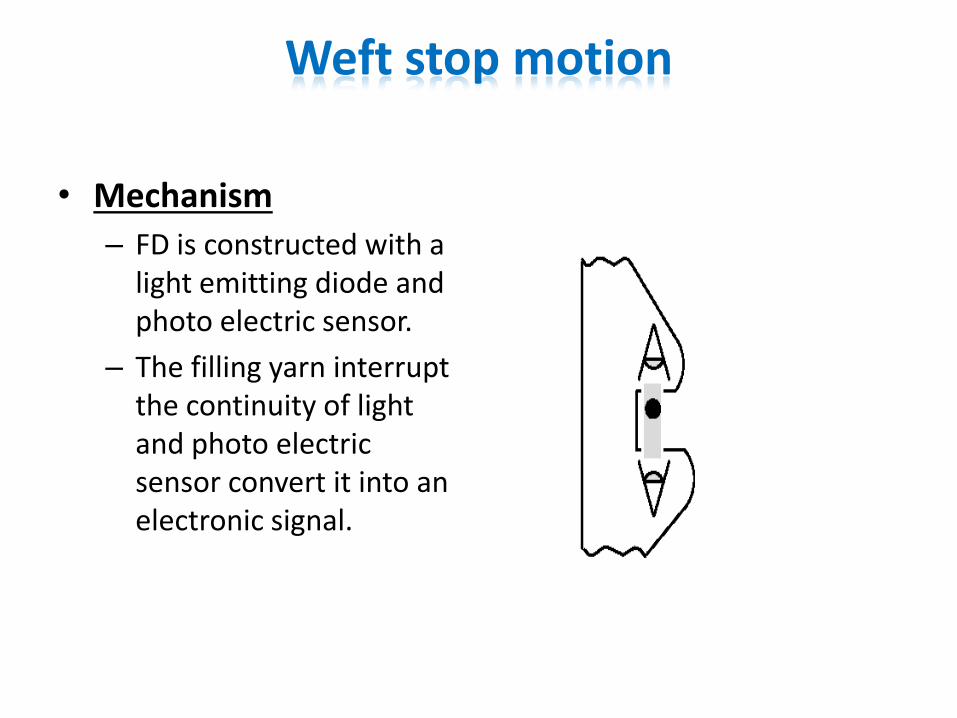
• Mechanism
– FD is constructed with a light emitting diode and photo electric sensor.
– The filling yarn interrupt the continuity of light and photo electric sensor convert it into an electronic signal.
Weft stop motion
Others stop motion
• Bobbin breakage
• Leno breakage
• Catch cord breakage
• Batcher stop
• Machine brake


![Untitled-2 [] Jacquard Electronic Attachment Jacquard Rapier Loom Accessories Electronic Jacquard Accessories ... Textile Machinery . …](https://static.fdocuments.us/doc/165x107/5aa7c0547f8b9a424f8cb782/untitled-2-jacquard-electronic-attachment-jacquard-rapier-loom-accessories-electronic.jpg)


