Air Intrusion vs. Air Leakage: The Dilemma for Low-Sloped...
7
T he majority of low-sloped roofs are constructed as convention- al membrane roofing assem- blies (membrane above insula- tion). Currently, four types of conventional assemblies are typically in use: • Mechanically attached assembly, • Loose-laid, ballasted assembly, • Fully bonded assembly (insulation- fastened and membrane-adhered), and Figure 1A – Billowing of mechanically attached TPO membrane in the field (Photo courtesy of Hans Gerhardt). Figure 1B – Billowing of mechanically attached TPO membrane in the lab. • Adhesive-applied assembly (all com- ponents fully adhered). Approximately one fourth of North American low-slope/commercial buildings are roofed with mechanically attached assemblies (NRCA 2004), and their popular- ity continues to grow. This paper differenti- ates the air intrusion and air leakage per- formance of the mechanically attached assembly. The waterproofing membrane, the key component of mechanically attached roofs, is available in three different types: • Modified bituminous membranes (mod bit), i.e., asphaltic-based, with a width of 3.3 ft (1 m), • Thermosets, including the common- ly used ethylene propylene diene monomer (EPDM), also known as ethylene propylene diene terpoly- mer, and • Thermoplastics, encompassing a wider variety of roofing membranes, the most common of which are polyvinyl chloride (PVC) and thermo- plastic olefin (TPO). Both thermoset and thermoplastic membranes employ different seaming tech- niques due to their different chemical, 4 • I NTERFACE N OVEMBER 2009
Transcript of Air Intrusion vs. Air Leakage: The Dilemma for Low-Sloped...

The majority of low-sloped roofs are constructed as conventional membrane roofing assemblies (membrane above insulation). Currently, four types of conventional assemblies are
typically in use: • Mechanically attached assembly, • Loose-laid, ballasted assembly, • Fully bonded assembly (insulation
fastened and membrane-adhered), and
Figure 1A – Billowing of mechanically attached TPO membrane in the field (Photo courtesy of Hans Gerhardt).
Figure 1B – Billowing of mechanically attached TPO membrane in the lab.
• Adhesive-applied assembly (all components fully adhered).
Approximately one fourth of North American low-slope/commercial buildings are roofed with mechanically attached assemblies (NRCA 2004), and their popularity continues to grow. This paper differentiates the air intrusion and air leakage performance of the mechanically attached assembly.
The waterproofing membrane, the key component of mechanically attached roofs, is available in three different types: • Modified bituminous membranes
(mod bit), i.e., asphaltic-based, with a width of 3.3 ft (1 m),
• Thermosets, including the commonly used ethylene propylene diene monomer (EPDM), also known as ethylene propylene diene terpolymer, and
• Thermoplastics, encompassing a wider variety of roofing membranes, the most common of which are polyvinyl chloride (PVC) and thermoplastic olefin (TPO).
Both thermoset and thermoplastic membranes employ different seaming techniques due to their different chemical,
4 • I N T E R F A C E N O V E M B E R 2 0 0 9

Figure 1C – Billowing of mechanically attached EPDM membrane in the field. (Photo, courtesy of Tom Kelly).
Figure 1D – Billowing of mechanically attached EPDM
membrane in the lab.
physical, and mechanical properties. Typically, they are available in widths from 6 to 12 ft (1.8 to 3.6 m). Membranes are installed in sheets and attached to the structural substrate (such as a steel deck) using mechanical fasteners. The attachment locations are then overlapped as seams, which are joined using different seaming techniques specific to the membrane type. Figure 1 shows the membrane response of the three different mechanically attached assemblies for both field and laboratory conditions.
Although research has been directed to the characterization of individual roof components such as the membrane, relatively little attention has been given to how air movement affects system performance. It has been incorrectly assumed that air movement in roofing assemblies is similar to air movement in wall assemblies. Several factors contribute to this misconception, including existing energy and building-code requirements and the current air-barrier standards, which are all focused on
Figure 1E – Billowing of mechanically
attached mod bit membrane in the lab.
N O V E M B E R 2 0 0 9 I N T E R F A C E • 5
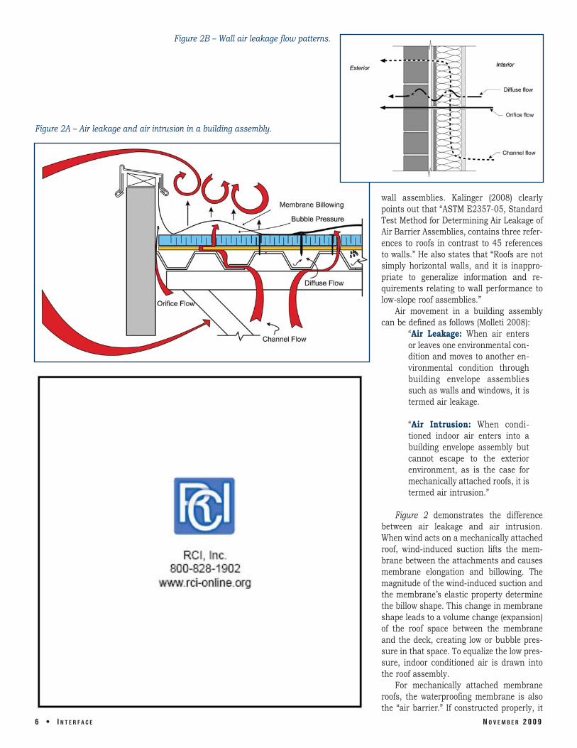
Figure 2B – Wall air leakage flow patterns.
Figure 2A – Air leakage and air intrusion in a building assembly.
wall assemblies. Kalinger (2008) clearly points out that “ASTM E2357-05, Standard Test Method for Determining Air Leakage of Air Barrier Assemblies, contains three references to roofs in contrast to 45 references to walls.” He also states that “Roofs are not simply horizontal walls, and it is inappropriate to generalize information and re quirements relating to wall performance to low-slope roof assemblies.”
Air movement in a building assembly can be defined as follows (Molleti 2008):
“Air Leakage: When air enters or leaves one environmental condition and moves to another en
6 • I N T E R F A C E
vironmental condition through building envelope assemblies such as walls and windows, it is termed air leakage.
“Air Intrusion: When conditioned indoor air enters into a building envelope assembly but cannot escape to the exterior environment, as is the case for mechanically attached roofs, it is termed air intrusion.”
Figure 2 demonstrates the difference between air leakage and air intrusion. When wind acts on a mechanically attached roof, wind-induced suction lifts the membrane between the attachments and causes membrane elongation and billowing. The magnitude of the wind-induced suction and the membrane’s elastic property determine the billow shape. This change in membrane shape leads to a volume change (expansion) of the roof space between the membrane and the deck, creating low or bubble pressure in that space. To equalize the low pressure, indoor conditioned air is drawn into the roof assembly.
For mechanically attached membrane roofs, the waterproofing membrane is also the “air barrier.” If constructed properly, it
N O V E M B E R 2 0 0 9

certainly prevents air leaving or entering a building through the roof. From a material perspective, the membrane is impermeable, a fact that can be proven by permeability data (Bomberg and Kumaran, 1985; CMHC, 1988). However, from an assembly perspective, the question arises whether the interaction between the different roof components caused by wind uplift and resulting in billowing (Figure 1) leads to air leakage through a roofing assembly.
The Dynamic Roofing Facility (DRF) at the National Research Council of Canada (NRC/IRC) has been conducting research on the wind uplift performance of membrane roofing assemblies for the past decade. CSA A123.21-04, Standard Test Method for the Dynamic Wind Uplift Resistance of Mechanically Attached Membrane-Roofing Systems, was developed at DRF and is the only North American test procedure for assessing the wind-load uplift resistance of mechanically attached roofing systems under dynamic wind-load conditions. Several roofing configurations have been evaluated using this test protocol, and an extensive wind uplift database has been created. One of the key observations from this database is that there is no air leakage
Figure 3 – Membrane and insulation pressure distribution during wind uplift tests.
in mechanically attached roofing assem- formance data of mechanically attached blies; there is air intrusion, which will be dis- thermoplastic and thermoset roofing cussed herein. assemblies. In this example, the thermo-
Figure 3 shows typical wind uplift per- plastic membrane sustained a wind uplift
N O V E M B E R 2 0 0 9 I N T E R F A C E • 7

Figure 4 – Membrane and insulation response during wind uplift testing of a mechanically attached roofing assembly.
pressure of 90 psf (4.3 kPa) and resulted in membrane but on top of the insulation. As a low pressure on the insulation of 55 psf previously mentioned, the insulation pres(2.6 kPa). The insulation pressure is mea- sure is caused due to the volume change of sured by a pressure tap installed below the the ballooning membrane and can also be
called “bubble pressure,” as shown in Figure 2. The range of the bubble pressure depends on the airtightness of the subsurface components below the membrane and the pressure equalization time. Regardless of the assembly type, test results indicated that the pressure distribution across the insulation ranges from 40% to 60% of the membrane pressure.
Figure 4 plots the roof-assembly response in terms of membrane pressure, insulation pressure, and membrane deflection for about five wind gusts at a pressure level of 4.3 kPa (90 psf), with each gust having a duration of about eight seconds. Within the eight-second period, the membrane experiences the maximum pressure of 4.3 kPa (90 psf) for two seconds and deflects about nine inches. This deflection or billowing of the membrane creates a low or bubble pressure below the membrane across the insulation, which is 40% to 60% of the membrane pressure.
It should be noted that, unlike the membrane pressure (which holds for the duration of the two-second gust cycle), the insulation pressure does not hold during the gust cycle. As shown in Figure 4, the insulation pressure builds up to 2.3 kPa (50 psf) and drops down without holding for the two-second gust cycle. This pressure drop could be attributed to the involved joints of the steel deck, insulation, and the fastener penetrations.
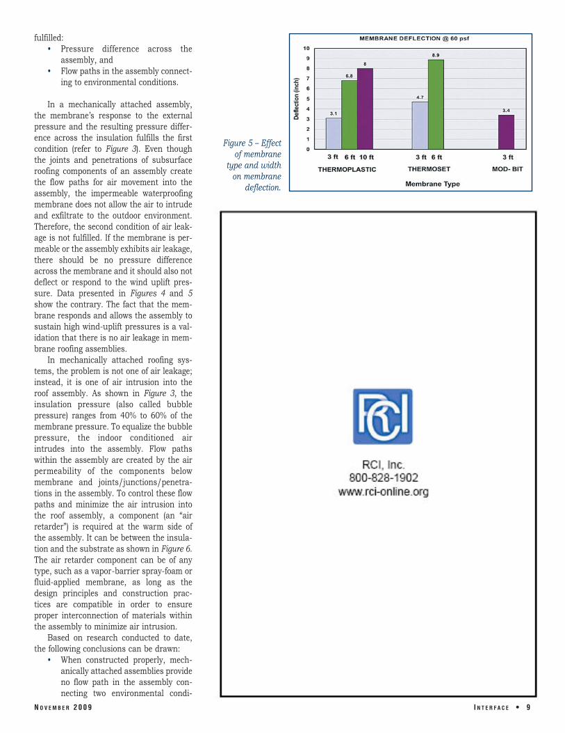
The pressure distribution varies across the insulation, depending on the extent of membrane deflection. The deflection de pends on the membrane elasticity and type, the membrane attachment arrangement, and the airtightness of the subsurface components. Figure 5 compares the membrane deflections for three membrane types of different widths under the same test pressure of 60 psf. It clearly shows that regardless of membrane type, deflection increases with an increase in membrane width. For similar sheet widths, the thermoset membrane had higher deflection compared with the thermoplastic membrane. This is indicative of the elastic nature of the thermoset, and it also verifies the role of elasticity on the membrane deflection (refer to Figure 1).
The foregoing information described the response of mechanically attached roofing assemblies. What remains unanswered is whether or not this response among the different roof components leads to air leakage in these assemblies. In other words, are these systems vulnerable to air leakage? For air leakage to occur, two conditions must be
8 • I N T E R F A C E N O V E M B E R 2 0 0 9
fulfilled: • Pressure difference across the
assembly, and • Flow paths in the assembly connect
ing to environmental conditions.
In a mechanically attached assembly, the membrane’s response to the external pressure and the resulting pressure difference across the insulation fulfills the first condition (refer to Figure 3). Even though the joints and penetrations of subsurface roofing components of an assembly create the flow paths for air movement into the assembly, the impermeable waterproofing membrane does not allow the air to intrude and exfiltrate to the outdoor environment. Therefore, the second condition of air leakage is not fulfilled. If the membrane is permeable or the assembly exhibits air leakage, there should be no pressure difference across the membrane and it should also not deflect or respond to the wind uplift pressure. Data presented in Figures 4 and 5 show the contrary. The fact that the membrane responds and allows the assembly to sustain high wind-uplift pressures is a validation that there is no air leakage in membrane roofing assemblies.
In mechanically attached roofing systems, the problem is not one of air leakage; instead, it is one of air intrusion into the roof assembly. As shown in Figure 3, the insulation pressure (also called bubble pressure) ranges from 40% to 60% of the membrane pressure. To equalize the bubble pressure, the indoor conditioned air intrudes into the assembly. Flow paths within the assembly are created by the air permeability of the components below membrane and joints/junctions/penetra tions in the assembly. To control these flow paths and minimize the air intrusion into the roof assembly, a component (an “air retarder”) is required at the warm side of the assembly. It can be between the insulation and the substrate as shown in Figure 6. The air retarder component can be of any type, such as a vapor-barrier spray-foam or fluid-applied membrane, as long as the design principles and construction practices are compatible in order to ensure proper interconnection of materials within the assembly to minimize air intrusion.
Based on research conducted to date, the following conclusions can be drawn:
• When constructed properly, mech anically attached assemblies provide no flow path in the assembly connecting two environmental condi-
N O V E M B E R 2 0 0 9
Figure 5 – Effect of membrane
type and width on membrane
deflection.
I N T E R F A C E • 9

Sheathing,” Building Research Note No. 227, National Research Council, Ottawa, Canada, April 1985.
CSA A123.21-04, Standard Test Method for the Dynamic Wind Uplift Resistance of Mechanically Attached
tions due to the impermeability of the waterproofing membrane, and therefore, membrane roofs are not prone to “air leakage.”
• Wind uplift testing indicates that membrane billowing results in a pressure difference of 40% to 60% across the insulation. If a membrane is air permeable or an assembly has air leakage, then there would be zero pressure distribution across the insulation. Thus, test data confirm there is no air leakage in membrane roofing assemblies.
• The bubble pressure due to a membrane’s billowing response can cause air intrusion. The airflow paths within the components can allow the air intrusion to occur.
• Installing an air retarder on the deck at the warm side of the assembly can control the air intrusion pro cess. A thorough understanding of design principles and construction practices is required to ensure the compatibility of the air retarder materials with the roofing assembly components.
REFERENCES Air Permeance of Building Materials,
Canada Mortgage and Housing Cor poration (CMHC), Ottawa, Canada, 1988.
American Society of Testing and Materials (ASTM) E2357 – 2005, Standard Test Method for Determining Air Leakage of Air Barrier Assemblies.
M. Bomberg and M.K. Kumaran, “A Test Method to Determine Air Flow Re sistance of Exterior Membranes and
1 0 • I N T E R F A C E
Figure 6 – Installation of air retarder on the deck at the warm side of the assembly.
Membrane-Roofing Systems, Cana dian Standards Association, Cana da, 2004.
Mark S. Graham, “Hurricane Charley: A Preliminary Report,” Professional Roofing, National Roofing Contrac tors Association, p. 73, October 2004.
Peter Kalinger, “The Roof as an Air Barrier,” Proceedings of the RCI 23rd International Convention & Trade Show, Phoenix, Arizona, February 28 - March 4, 2008.
S. Molleti and A. Baskaran, “Devel opment of a New Test Method for Air Intrusion Quantification of Roofing Assemblies,” ASTM Journal of Test ing and Evaluation, 36(3), pp. 230241, 2008.
Bas Baskaran, PhD
Dr. Bas Baskaran is a group leader for the Roofing Sub-Program at the National Research Council of Canada, Institute for Research in Construction (NRC/IRC). At the NRC, he is researching the wind effects on building envelopes through experiments and computer modeling. He also acts as adjunct professor at the University of Ottawa. He is the vice-chairperson for the Roofing Committee on Weather Issues (RICOWI) and a member of RCI, Inc., ASCE, SPRI, and CIB technical committees. He has authored and/or coauthored over 200 research articles in the area of wind effects on buildings. Baskaran received his bachelor’s degree in engineering from Annamalai University, Madras, India. His master’s and doctoral degrees in engineering were from Concordia University, Montreal, Canada. Both research topics focused on the wind effects on buildings and earned best dissertation awards from the Canadian Society of Civil Engineers.
Sudhakar Molleti, PhD
Dr. Sudhakar (Suda) Molleti is a research officer in the roofing subprogram (Performance of Roofing Systems and Insulation [PRSI]) at the National Research Council of Canada, Institute for Research in Construction NRC/IRC). His work focuses on researching the wind-induced effects on low-sloped roofing systems through experiments and finite element modeling; air-intrusion quantification and its impact on roofing system performance; the dimensional stability of low-sloped roofing systems; and calculation of roof cladding wind-design loads
using the NBCC and ASCE design codes. He is a member of the ASTM D08 and CRCA technical committees. Suda received his BS in civil engineering from the Gandhi Institute of Technology and Management, Andhra Pradesh, India. His MS and PhD in engineering were from the University of Ottawa, Ottawa, Canada. His PhD thesis focused on the performance evaluation of mechanically attached roofing systems with emphasis on numerical modeling of table-edge effect and air-intrusion quantification.
N O V E M B E R 2 0 0 9