Air Interface Layer 2 2 - National Chengchi Universityjang/teaching/MobileMgt_files/Air...
68
Air Interface Layer 2
Transcript of Air Interface Layer 2 2 - National Chengchi Universityjang/teaching/MobileMgt_files/Air...

Air Interface Layer 2

Contents
• 1. Medium Access Control Protocol!
• 2. Radio Link Control Protocol!
• 3. Packet Data Convergence Protocol

1. Medium Access Control Protocol
• 1.1 Protocol Architecture!
• 1.2 Timing Advance Commands!
• 1.3 Buffer Status Reporting!
• 1.4 Power Headroom Reporting!
• 1.5 Multiplexing and De-Multiplexing!
• 1.6 Logical Channel Prioritization!
• 1.7 Scheduling of Transmissions on the Air Interface

• Three protocols in data link layer (Layer 2) of LTE air interface!
✓ Medium Access Control (MAC) protocol!
- Schedules all the transmissions that are made on the LTE air interface!
- Controls the low-level operation of the physical layer!
✓ Radio Link Control (RLC) protocol!
- Maintains the data link across the air interface, if necessary by re-transmitting packets that the physical layer has not delivered correctly!
✓ Packet Data Convergence Protocol (PDCP)!
- Maintains the security of the air interface!
- Compresses the headers of IP packets!
- Ensures the reliable delivery of packets after a handover

1.1 Protocol Architecture• Medium access control (MAC)
protocol!
✓ Schedules all the transmissions that are made on the LTE air interface!
✓ Controls the low-level operation of the physical layer!
• There is one MAC entity in the BS and one in the mobile!
• The figure is a high-level block diagram of the mobile’s MAC protocol
MAC:Medium Access Control RLC:Radio Link Control PDCP:Packet Data Convergence Protocol

Figure 10.1 High-level architecture of the mobile’s MAC protocol.

• In the transmitter!
✓ The logical channel prioritization function determines how much data the mobile should transmit from each incoming logical channel in every transmission time interval!
• In response!
✓ The mobile grabs the required data from transmit buffers in the RLC protocol, in the form of MAC Service Data Units (SDUs)!
• The multiplexing function!
✓ Combines the SDUs together, attaches a header and sends the resulting data on a transport channel to the physical layer by way of hybrid ARQ transmission function
Transport block The MAC protocol sends information to the physical layer in the form of transport blocks. The size of each transport block is defined by the downlink control information, while its duration is the 1 ms transmission time interval.

• The hybrid ARQ transmission!
✓ Controls the operation of the physical layer’s hybrid ARQ protocol!
• The output data packets!
✓ Known as MAC Protocol Data Units (PDUs) and are identical to the transport blocks!
• The functions are reversed in the mobile’s receiver
Transport block The MAC protocol sends information to the physical layer in the form of transport blocks. The size of each transport block is defined by the downlink control information, while its duration is the 1 ms transmission time interval.

• BS’s MAC protocol!
✓ Carry out transmissions to different mobiles on the downlink and receive transmissions from different mobiles on the uplink!
✓ The protocol includes a scheduling function !
- Organizes BS’s transmissions on the downlink and mobiles’ transmissions on the uplink!
- Determines the contents of the PDCCH (Physical Downlink Control CHannel) scheduling commands and scheduling grants

• The MAC protocol also sends and receives a number of MAC control elements, which control the low-level operation of the physical layer
Table 10.1 List of MAC control elements

• During discontinuous reception in RRC_CONNECTED, BS can send mobile to sleep using a DRX (Discontinuous Reception) command!
• UE contention resolution identity and C-RNTI (Cell Radio Network Temporary Identifier) control elements are both used by the contention based random access procedure
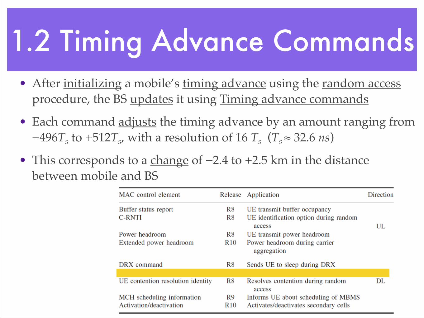
1.2 Timing Advance Commands• After initializing a mobile’s timing advance using the random access
procedure, the BS updates it using Timing advance commands !
• Each command adjusts the timing advance by an amount ranging from −496Ts to +512Ts, with a resolution of 16 Ts (Ts ≈ 32.6 ns)!
• This corresponds to a change of −2.4 to +2.5 km in the distance between mobile and BS

• The mobile expects to receive timing advance commands from the BS at regular intervals!
✓ The maximum permitted interval is a quantity known as timeAlignmentTimer, which can take a value from 500 to 10240 subframes (0.5 to 10.24 seconds)!
✓ If the time elapsed since the previous timing advance command exceeds this value, then the mobile concludes that it has lost timing synchronization with BS

1.3 Buffer Status Reporting• The mobile transmits Buffer
Status Report (BSR) to tell the BS about how much data it has available for transmission!
• There are three types of buffer status report!
✓ Regular BSR!
✓ Periodic BSR!
✓ Padding BSRs!
✓ The most important is the regular BSR

• A mobile sends regular BSR in three situations!
✓ If data become ready for transmission when the transmit buffers were previously empty!
✓ If data become ready for transmission on a logical channel with a higher priority than the buffers were previously storing!
✓ If a timer expires while data are waiting for transmission!
• The mobile expects the BS to reply with a scheduling grant

• If the mobile wishes to send a regular BSR, but does not have the PUSCH (Physical Uplink Shared Channel) resources on which to do so, then it instead sends the BS a scheduling request on the PUCCH (Physical Uplink Control Channel)!
• Two other types of buffer status report!
✓ The mobile transmits periodic BSRs at regular intervals during data transmission on the PUSCH!
✓ Padding BSRs if it has enough spare room during a normal PUSCH transmission

1.4 Power Headroom Reporting
• A mobile’s power headroom [功率餘裕] is the difference between its maximum transmit power and the power requested for its PUSCH transmission !
• The power headroom is usually positive, but it can be negative if the requested power exceeds the power available

• The mobile reports its power headroom to the BS using a power headroom MAC control element!
• It can do so in two situations!
✓ Periodically !
✓ If the downlink path loss has changed significantly since the last report!
• The BS uses the information to support its uplink scheduling procedure, typically by limiting the data rate at which it asks the mobile to transmit

1.5 Multiplexing and De-Multiplexing
• What is the internal structure of a MAC Protocol Data Unit (PDU) and how the way in which it is assembled?!
• In its most general form, a MAC PDU (MAC payload) contains!
✓ Several MAC SDUs!
- Each SDU contains data received from the RLC on a single logical channel!
✓ Several control elements!
✓ Padding!
- Rounds the protocol data unit up to one of the permitted transport block sizes
(MAC PDU)

Figure 10.2 Structure of a MAC PDU.
(MAC PDU)

• Each item in the MAC payload is associated with a sub-header !
✓ The SDU sub-header identifies!
- The size of the SDU!
- The logical channel from which it originated!
✓ The control element sub-header identifies!
- The control element’s size and type
(MAC PDU)

• In the uplink!
✓ The mobile discovers the required PDU size from the BS’s scheduling grant!
✓ Using the prioritization algorithm described below, the mobile!
- Decides how it will fill the available space in the PDU!
- Grabs SDUs from the buffers in the overlying RLC protocol!
- Grabs control elements from the MAC control unit!
✓ The multiplexing function then writes the corresponding sub-headers and assembles the PDU!
• The same technique is used in the downlink, but the prioritization process is rather different

1.6 Logical Channel Prioritization• The BS tells the mobile about the size of every uplink MAC PDU using its
scheduling grant!
✓ The scheduling grant says nothing about what the protocol data unit should contain!
• The mobile therefore runs a prioritization algorithm, to decide how to fill it!
✓ Each logical channel is associated with!
- A priority from 1 (highest priority) to 16!
- A prioritized bit rate (PBR), which runs from zero to 256 kbps and is a target for the long-term average bit rate!
‣ The specifications support an infinite prioritized bit rate, with the interpretation ‘as fast as possible’!
✓ These parameters are all derived from the QoS parameters

• The prioritization algorithm is fully defined by the MAC protocol specification and the principles are as follows!
✓ First, the MAC runs through the logical channels in order of priority and grabs data from channels that have fallen behind their long-term average bit rates!
✓ It then runs through the channels in priority order once again and fills any space in the PDU that remains!
✓ The algorithm also prioritizes the control elements, and the resulting priority order is as follows!
- Data on the common control channel together with any associated C-RNTI (Cell Radio Network Temporary Identifier) control elements!
- Regular or periodic buffer status reports!
- Power headroom reports!
- Data on other logical channels!
- Padding buffer status reports

• Prioritization in the downlink!
✓ It is rather different with uplink, because BS is free to fill up the PDUs in any way that it likes!
✓ In practice, the downlink prioritization algorithm will form part of the proprietary scheduling algorithm that we discuss below

1.7 Scheduling of Transmissions on the Air Interface
• The BS’s scheduling algorithm has to decide the contents of every downlink scheduling command and uplink scheduling grant, on the basis of all the information available to it at the time!
• The following figure shows some of the main inputs and outputs of the algorithm

Figure 10.3 Inputs and outputs for the uplink and downlink scheduling algorithms.

• The information available to the downlink scheduler includes the following!
✓ Each bearer is associated with a buffer occupancy, as well as information about its QoS such as the priority and prioritized bit rate that we introduced earlier!
• To support the scheduling function, the mobile returns!
✓ Hybrid ARQ acknowledgements!
✓ Channel quality indicators!
✓ Rank indications

• The BS also knows the discontinuous reception (DRX) pattern for every mobile in the cell and can receive load information from nearby cells about their own use of the downlink sub-carriers!
• Using this information, the scheduler has to!
✓ Decide how many information bits to send to each mobile!
✓ Whether to send a new transmission or a re-transmission!
✓ How to divide new transmissions amongst the available bearers!
✓ Decide the modulation schemes and coding rates to use!
✓ Decide the number of layers in the case of spatial multiplexing!
✓ Decide the allocation of resource blocks to every mobile

• The uplink scheduler follows the same principles, although some of the inputs and outputs are different!
✓ For example, the BS does not have complete knowledge of uplink buffer occupancy and does not tell the mobiles which logical channels they should use for their uplink transmissions !
✓ In addition, the BS derives its channel quality information from the sounding procedure, instead of from the mobiles’ channel quality indicators

• At a basic level, two extreme scheduling algorithms are available!
✓ (1) A maximum rate scheduler allocates resources to the mobiles with the highest SNRs, which can transmit or receive at the highest data rates!
- This maximizes the throughput of the cell but is grossly unfair, as distant mobiles may not get a chance to transmit or receive at all!
✓ (2) A round-robin scheduler gives the same data rate to every mobile!
- This is fair but grossly inefficient, as distant mobiles with low SNRs will dominate the cell’s use of resources!
✓ In practice, techniques such as proportional fair scheduling try to strike a balance between the two extremes

• 1. Medium Access Control Protocol!
• 2. Radio Link Control Protocol!
• 3. Packet Data Convergence Protocol

2. Radio Link Control Protocol
• 2.1 Protocol Architecture!
• 2.2 Transparent Mode!
• 2.3 Unacknowledged Mode!
• 2.4 Acknowledged Mode

2.1 Protocol Architecture• Radio Link Control (RLC) protocol maintains the layer 2 data link between mobile and BS!
✓ For example by ensuring reliable delivery for data streams that have to reach the receiver correctly!
• The following figure shows the high-level architecture of the RLC!
• The transmitter!
✓ Receives SDUs from higher layers in the form of modified IP packets or signaling messages!
✓ Sends PDUs to MAC protocol on the logical channels!
• The receiver!
✓ The process is reversed

Figure 10.4 High-level architecture of the RLC protocol.

• RLC has three modes of operation!
✓ Transparent Mode (TM) – uni-directional!
✓ Unacknowledged Mode (UM) – uni-directional!
✓ Acknowledged Mode (AM) – bi-directional!
• These are set up on a channel-by-channel basis, so that each logical channel is associated with an RLC object that is configured in one of these modes

2.2 Transparent Mode• Transparent mode handles three types of signaling
message!
✓ System information messages on the broadcast control channel (BCCH)!
✓ Paging messages on the paging control channel (PCCH)!
✓ RRC connection establishment messages on the common control channel (CCCH)
TM:Transparent Mode UM:Unacknowledged Mode AM:Acknowledged Mode

Figure 10.5 Internal architecture of the RLC protocol in transparent mode.

• In the transmitter!
✓ The RLC receives signaling messages directly from RRC protocol, and stores them in a buffer!
✓ The MAC protocol grabs the messages from the buffer as RLC PDUs, without any modification!
• In the receiver!
✓ The RLC passes the received messages directly up to the RRC

2.3 Unacknowledged Mode• Unacknowledged mode handles data streams
on the dedicated traffic channel for which timely delivery is more important than reliability, such as voice over IP and streaming video
TM:Transparent Mode UM:Unacknowledged Mode AM:Acknowledged Mode

• RLC transmitter receives SDUs from PDCP in the form of modified IP packets and stores them in a buffer in the same way as before!
• This time, MAC protocol tells RLC to send it a PDU with a specific size!
• In response, the segmentation and concatenation function cuts up the buffered IP packets and splices [黏接] their ends together, so as to deliver a PDU with the correct size down to the MAC

• As a result, the output PDU size does not bear any resemblance to the size of the input SDU!
• Finally, the RLC adds a header that contains two important pieces of information!
✓ A PDU sequence number!
✓ A description of any segmentation and concatenation that it has done

• PDUs can reach the receiver’s RLC protocol in a different order, because of the underlying hybrid ARQ processes!
✓ To deal with this problem, the hybrid ARQ re-ordering function stores the received PDUs in a buffer, and uses their sequence numbers to send them upwards in the correct order!
• The receiver can then remove the header from every PDU, use the header information to undo the segmentation and concatenation process and reconstruct the original packets

Figure 10.6 Internal architecture of the RLC protocol in unacknowledged mode.

2.4 Acknowledged Mode• Acknowledged mode handles two types of
information!
✓ Data streams on the dedicated traffic channel such as web pages and emails, for which reliability is more important than speed of delivery!
✓ Mobile-specific signaling messages on the dedicated control channel !
• Re-transmits any packets that have not reached the receiver correctly
TM:Transparent Mode UM:Unacknowledged Mode AM:Acknowledged Mode

• The following architecture is bi-directional, in the sense that the same acknowledged mode object handles transmission and reception!
• Two types of PDU!
✓ Data PDUs carry higher-layer data and signaling messages!
✓ Control PDUs carry RLC-specific control information

Figure 10.7 Internal architecture of the RLC protocol in acknowledged mode.

• The transmitter!
✓ Sends data packets in a similar way to the unacknowledged mode RLC!
✓ This time, it stores the transmitted PDUs in a re-transmission buffer, until it knows that they have reached the receiver correctly!
✓ At regular intervals, the transmitter also sets a polling bit in one of the data PDU headers!
✓ This tells the receiver to return a type of control PDU known as a status PDU, which lists the data PDUs it has received and the ones it has missed !
✓ In response, the transmitter discards the data PDUs that have arrived correctly and re-transmits the ones that have not

• If the SINR is falling, then the MAC protocol may request a smaller PDU size for re-transmission than it did first time around!
✓ The PDUs in the re-transmission buffer will then be too large to send!
✓ To solve the problem, the RLC protocol can cut a previously transmitted PDU into smaller segments!
✓ To support this process, the data PDU header includes extra fields, which describe the position of a retransmitted segment within a previously transmitted PDU!
• The receiver can acknowledge each segment individually, using similar fields in the status PDU (type of control PDU)

• The following figure shows that at the start of the sequence, the transmitter sends four data PDUs to the receiver and labels each one with a sequence number !
✓ PDUs 1 and 4 reach the receiver correctly, but PDUs 2 and 3 are lost

Figure 10.8 Operation of transmission, re-segmentation and re-transmission in RLC acknowledged mode.

• The transmitter sets a polling bit in PDU 4 and the receiver replies by returning a status PDU!
• The transmitter can re-transmit PDU 2, but a fall in the SINR means that PDU 3 is now too large!
• In response, the transmitter cuts PDU 3 into two segments and re-transmits them individually!
✓ The first segment of PDU 3 arrives correctly, but the second is lost!
✓ In response to another status PDU, the transmitter can discard the first segment and can re-transmit the second

• 1. Medium Access Control Protocol!
• 2. Radio Link Control Protocol!
• 3. Packet Data Convergence Protocol

3. Packet Data Convergence Protocol
• 3.1 Protocol Architecture!
• 3.2 Header Compression!
• 3.3 Prevention of Packet Loss During Handover

3.1 Protocol Architecture• Packet Data Convergence Protocol (PDCP)
supports data streams that are using RLC acknowledged mode, by ensuring that none of their packets are lost during a handover!
• It also manages three air interface functions!
✓ Header compression!
✓ Ciphering!
✓ Integrity protection

• The PDCP is only used by the dedicated traffic and control channels, for which the underlying RLC protocol is operating in unacknowledged or acknowledged mode!
• There are different architectures for data and signaling

Figure 10.9 Architecture of the PDCP.

• In the user plane, the transmitter!
✓ Receives PDCP SDUs in the form of IP packets!
✓ Adds a PDCP sequence number!
✓ Stores any packets that are using RLC acknowledged mode in a re-transmission buffer !
✓ It then compresses the IP headers, ciphers the information, adds a PDCP header and outputs the resulting PDU

• In the user plane, the receiver reverses the process!
✓ Stores incoming packets in the receive buffer!
✓ Uses the sequence number to deliver them in the correct order to higher layers

• In the control plane!
✓ The signaling messages are protected by an extra security procedure, known as integrity protection!
✓ There is no re-transmission buffer, because the re-transmission function is only used for data !
✓ There are no IP headers to compress

3.2 Header Compression• Headers can make up a large proportion of a slow packet data
stream!
• In the case of voice over IP, for example, the narrowband adaptive multi rate codec has a maximum bit rate of 12.2 kbps and a packet duration of 20 ms, giving a typical packet size of 31 bytes!
• However, the header typically contains 40 or 60 bytes, comprising !
✓ 12 bytes from the Real Time Protocol (RTP)!
✓ 8 bytes from UDP!
✓ Either 20 bytes from IP version 4 or 40 bytes from IP version 6!
✓ Such an overhead is inappropriate across the bottleneck of the air interface

• To solve the problem, the PDCP includes a Robust Header Compression (ROHC) protocol !
✓ The transmitter sends the full header in the first packet, but only sends differences in subsequent packets!
✓ Most of the header stays the same from one packet to the next, so the difference fields are considerably smaller!
✓ The protocol can compress the original 40 and 60 byte headers to as little as 1 and 3 bytes respectively, which greatly reduces the overhead

• Advantage of ROHC protocol!
✓ It is designed to work well even if the underlying rate of packet loss is high!
✓ Suitable for an unreliable data link such as LTE air interface, particularly for real-time data streams, such as voice over IP, that are using RLC unacknowledged mode

3.3 Prevention of Packet Loss During Handover
• When transmitting data streams that are using RLC acknowledged mode!
✓ The PDCP stores each SDU in a re-transmission buffer, until the RLC tells it that the SDU has been successfully received!
• During a handover!
✓ The processes of transmission and reception are briefly interrupted, so there is a risk of packet loss!
• On completion of the handover!
✓ The PDCP solves the problem by re-transmitting any SDUs that it is still storing

• A secondary problem: some of those SDUs may actually have reached the receiver, but the acknowledgements may have been lost instead!
✓ To prevent them from being transmitted twice, the system can use a PDCP status reporting procedure !
• The following figure shows the combined effect of the two procedures

Figure 10.10 PDCP status reporting and prevention of packet loss after a handover.

• Note that the messages in this figure apply only to bearers that are using RLC acknowledged mode!
• As part of the handover procedure, the old eNB !
✓ Sends the new eNB an X2-AP message known as SN Status Transfer, in which it lists the PDCP sequence numbers that it has received on the uplink !
✓ It also forwards any downlink PDCP SDUs that the mobile has not yet acknowledged, as well as any uplink SDUs that it has received out of sequence

• The new eNB!
✓ Send the mobile a PDCP control PDU known as a PDCP Status Report (step 1), in which it lists the sequence numbers that it has just received from the old BS !
• The mobile!
✓ Delete these from its re-transmission buffer, and only has to re-transmit the remainder (step 3)!
✓ At the same time, the mobile can send a PDCP Status Report to the new BS (step 2), in which it lists the PDCP sequence numbers that it has received on the downlink!
• The new BS can delete these in the same way, before beginning its own re-transmission (step 4)