MANUFACTURING TECHNOLOGY UNIT – V Machine Tools. Manufacturing Technology.

UNITED STATES AIR FORCE CIVIL ENGINEERING ADDITIVE
MANUFACTURING APPLICATIONS: TOOLS AND JIGS
THESIS
Bradford L. Shields, Captain, USAF
AFIT-ENV-16-M-182
DEPARTMENT OF THE AIR FORCE AIR UNIVERSITY
AIR FORCE INSTITUTE OF TECHNOLOGY
Wright-Patterson Air Force Base, Ohio
DISTRIBUTION STATEMENT A. APPROVED FOR PUBLIC RELEASE; DISTRIBUTION UNLIMITED.

The views expressed in this thesis are those of the author and do not reflect the official policy or position of the United States Air Force, Department of Defense, or the United States Government. This material is declared a work of the U.S. Government and is not subject to copyright protection in the United States.

AFIT-ENV-16-M-182
UNITED STATES AIR FORCE CIVIL ENGINEERING ADDITIVE MANUFACTURING APPLICATIONS: TOOLS AND JIGS
THESIS
Presented to the Faculty
Department of Systems Engineering and Management
Graduate School of Engineering and Management
Air Force Institute of Technology
Air University
Air Education and Training Command
In Partial Fulfillment of the Requirements for the
Degree of Master of Science in Engineering Management
Bradford L. Shields, B.S., M.B.A.
Captain, USAF
March 2016
DISTRIBUTION STATEMENT A. APPROVED FOR PUBLIC RELEASE; DISTRIBUTION UNLIMITED.

AFIT-ENV-16-M-182
UNITED STATES AIR FORCE CIVIL ENGINEERING ADDITIVE MANUFACTURING APPLICATIONS: TOOLS AND JIGS
Bradford L. Shields, B.S., M.B.A. Captain, USAF
Committee Membership:
Maj Vhance V. Valencia, USAF, PhD Chair
Joseph D. Wander, PhD Member
Alfred E. Thal, Jr. PhD Member

1
AFIT-ENV-16-M-182
Abstract
Additive manufacturing is a technology revolutionizing the manufacturing
industry. By creating three-dimensional objects from the ground up, the technology does
away with the traditional manufacturing methods used to design and create products.
This research examines the application of additive manufacturing (AM) to fabricate tools
and jigs in United States Air Force civil engineering (CE) operations. Within this
research, numerous parts were designed and printed for use within CE operations. After
testing of the parts, a usability survey was conducted to validate the need and potential
for AM within a CE unit.
The results of the part testing and the resultant survey indicate that AM will
definitely impact the daily operations of a CE unit and that a clear need exists for the use
of AM. Further, the research determined that AM has reached a point that the integration
of AM into strategically coordinated units, along with proper education and training, can
be beneficial for the CE career field. Finally, the results indicate that 3D scanning
technology will reach a point within the next 5 years where it can help foster the rapid
build-up of 3D CE asset designs for printing applications. The overall results push
forward the Air Force’s 3D printing capability while providing critical information for
decision-makers on this up-and-coming technology.

2
Dedication
“I can do all things through Christ, who strengthens me” – Philippians 4:13
My thesis is dedicated to my bride and newborn son. I could not have done it
without the constant support at home and the understanding during the late nights of
studying and writing. Also, thanks to my parents for instilling in me a drive to push
through tough times and always give my all in everything.

3
Acknowledgments
I would like to express my sincere appreciation to my past commanders, Lt Col
Chad B. Bondurant and Lt. Col Kenneth B. Herndon who pushed me to always continue
growing in education, professional development, and leadership. I would like to also
thank my advisor, Major Vhance V. Valencia, for the multiple reviews conducted on my
writing and the constant feedback to ensure I produced the best product possible. Thank
you as well to Dr. Thal for feedback and ideas, as well as Dr. Joseph Wander and the Air
Force Civil Engineer Center for sponsoring this research and providing funding. AFIT
has been the opportunity of a lifetime and I have enjoyed the education I have been
provided. Always remember, “You are only here once (YOHO)!”
Bradford L. Shields

4
Table of Contents
Page
Abstract ....................................................................................................................1
Dedication ................................................................................................................2
Acknowledgments....................................................................................................3
Table of Contents .....................................................................................................4
List of Figures ..........................................................................................................7
List of Tables ...........................................................................................................9
I. Introduction ........................................................................................................10
Background.....................................................................................................11
Problem Statement ..........................................................................................14
Research Objective and Investigative Questions ...........................................15
Research Overview .........................................................................................16
Research Limitations ......................................................................................18
II. Literature Review ..............................................................................................20
Chapter Overview ...........................................................................................20
Traditional Manufacturing ..............................................................................20 What is Traditional Manufacturing? ..................................................... 20 Casting or Molding ................................................................................ 21 Forming.................................................................................................. 21 Machining .............................................................................................. 22 Joining.................................................................................................... 22 How are the Four Types of Manufacturing Limited? ............................ 23 Creating a Product from Traditional Manufacturing: Start to Finish .. 23 What Value Does Traditional Manufacturing Create? ......................... 25 Disadvantages of Traditional Manufacturing? ..................................... 26
Additive Manufacturing .................................................................................29 What Is Additive Manufacturing? .......................................................... 29 Categories of 3D Printers ...................................................................... 30 Vat Photopolymerization ....................................................................... 31 Material Jetting ...................................................................................... 32 The Additive Manufacturing Process ..................................................... 33

5
Current State of 3D Printing Industry ................................................... 36
Systems Engineering Processes ......................................................................47 What is Systems Engineering? ............................................................... 47 Waterfall Process Model ........................................................................ 48 “Vee” Process Model ............................................................................ 49 Spiral Process Model ............................................................................. 51 Choosing a Systems Engineering Model ................................................ 52 Systems Engineering Properties: “-ilities” ........................................... 53 Usability .......................................................................................... 54 Usability: Effectiveness ................................................................... 55 Usability: Efficiency ........................................................................ 56 Usability: Safety ............................................................................... 56 Usability: Utility .............................................................................. 57 Usability: Learnability ..................................................................... 57 Usability: Memorability ................................................................... 57
Summary.........................................................................................................58
III. Methodology ....................................................................................................59
Chapter Overview ...........................................................................................59
Systems Engineering Design Methodology ...................................................59 Requirements and Design Constraints................................................... 61 Risk Analysis .......................................................................................... 63 Design/Building – Iteration #1, 2, 3… ................................................... 65 Testing – Iteration #1, 2, 3… ................................................................. 65 Final Handoff, Integration, and Maintenance ....................................... 66 Systems Engineering Application ..................................................................66 Materials and Equipment ................................................................................67 Solidworks .............................................................................................. 67 Measuring Tools .................................................................................... 68 Additive Manufacturing Equipment ....................................................... 68 Post Processing Equipment ................................................................... 70 Procedures and Processes ...............................................................................70 Needs Identification ............................................................................... 72 Design Process ....................................................................................... 72 Product Printing .................................................................................... 73 Product Post Processing ........................................................................ 73 Product Testing ...................................................................................... 74 Usability Survey ..................................................................................... 74

6
Data Analysis ..................................................................................................77 Summary.........................................................................................................77
IV. Analysis and Results .......................................................................................79
Additively Manufactured Part Designs ..........................................................79 EOD Bracket Design.............................................................................. 79 EOD Bracket Survey Results ................................................................. 87 Computer Engineering Microchip Jig Design ....................................... 89 Computer Engineering Microchip Jig Survey Results ........................... 92 Utility Pipe Inspection Autonomous Vehicle Bracket Design ................ 94 Utility Pipe Inspection Autonomous Vehicle Bracket Survey Results . 104 Overall Usability Results ..................................................................... 108 Summary.......................................................................................................109
V. Conclusions and Recommendations ..............................................................110
Investigative Questions Answered ...............................................................110
Conclusions of Research ..............................................................................114
Significance of Research ..............................................................................116
Limitations of Research ................................................................................117
Recommendations for Action .......................................................................118 Duplication of Ex-labs/Print the Fleet ................................................. 119 Global 3D Design Sharepoint .............................................................. 120 Possibilities for Future Research ..................................................................121 Conclusion ....................................................................................................122
Appendix A – Internal Review Board Survey Exemption Package ....................123
References ............................................................................................................128
Vita .......................................................................................................................134

7
List of Figures
Page
Figure 1. Additive Manufacturing Process ...................................................................... 34
Figure 2. Waterfall Process Model .................................................................................. 49
Figure 3. “Vee” Process Model ....................................................................................... 50
Figure 4. Spiral Process Model ........................................................................................ 51
Figure 5. Spiral Process Model ........................................................................................ 60
Figure 6. ProJet™ 1500 Printer, Opened to View Printing Bed (right) .......................... 69
Figure 7. ProJet™ 3500 HD Max Printer ........................................................................ 69
Figure 8. ProJet™ Solvent Washing Basin ...................................................................... 70
Figure 9. ProJet™ Finisher Oven .................................................................................... 71
Figure 10. Northrop Grumman Remotec® Unmanned Ground Vehicle (left) (Cooper,
2011). Arm Assembly on the Northrop Grumman Remotec® UGV (right) ............. 80
Figure 11. Victoreen® Fluke® Biomedical 451P sensor ................................................ 82
Figure 12. Anchor Points and Hook Attachment for Bracket on the EOD UGV ............ 82
Figure 13. EOD Bracket with IdentiFINDER® R400 Attached ..................................... 85
Figure 14. EOD Bracket Design Progression (Six Iterations) ......................................... 86
Figure 15. EOD Bracket with Backpack Sensor Attached .............................................. 86
Figure 16. EOD Bracket with Two Sensors Attached ..................................................... 87
Figure 17. Computer Engineering Jig, Iteration 2 Design ............................................... 91
Figure 18. Computer Engineering Jig in Operational Use ............................................... 91
Figure 19. Autonomous Utility Inspection Vehicle ......................................................... 95
Figure 20 – Prosilica GC1290C Camera (AVT, (n.d.)) .................................................... 97

8
Figure 21. Autonomous Vehicle Front LIDAR and Camera Bracket Iteration #1 .......... 98
Figure 22. Autonomous Vehicle Front LIDAR and Camera Bracket Iteration #2 .......... 99
Figure 23. Front LIDAR and Camera Bracket Testing .................................................... 99
Figure 24. LiDAR Lite™ Range Finder (RobotShop, n.d.) .......................................... 100
Figure 25 – Autonomous Vehicle Rear LIDAR Camera Design ................................... 101
Figure 26. Autonomous Utility Inspection Vehicle Rear LIDAR Test ......................... 101
Figure 27. Autonomous Vehicle Large Battery Receptacle Design (left), Small Battery
Design (right) ........................................................................................................... 103
Figure 28. Autonomous Vehicle Battery Receptacle during Testing ............................ 104
Figure 29. Autonomous Vehicle Battery Receptacle Attached to Robot ...................... 104
Figure A - 1. IRB Exemption Letter (Dated: Nov 18th, 2015) ....................................... 123
Figure A - 2. IRB Memorandum for Exemption ........................................................... 124
Figure A - 3. IRB Memorandum for Exemption (Cont.) ............................................... 125
Figure A - 4. IRB Verbal Statement for Participants ..................................................... 126
Figure A - 5. Additive Manufacturing Survey ............................................................... 127

9
List of Tables
Page
Table 1. 3D Printing Categories (ASTM International, 2015) ......................................... 31
Table 2. Summary of Sensors .......................................................................................... 81
Table 3. EOD Bracket Usability Survey Results ............................................................. 88
Table 4. Computer Engineering Jig Overall Usability Results ........................................ 92
Table 5. UGV Front Camera Overall Usability Results ................................................ 105
Table 6. UGV Rear LIDAR Bracket Overall Usability Results .................................... 105
Table 7. UGV Large Battery Receptacle Bracket Overall Usability Results ...................... 106
Table 8. UGV Small Battery Receptacle Bracket Overall Usability Results ...................... 106
Table 9. Overall Usability Results ................................................................................. 108
10
UNITED STATES AIR FORCE ADDITIVE MANUFACTURING APPLICATIONS FOR CIVIL ENGINEER TOOLS AND JIGS
“If we could make a whole car door in less than a minute without any tooling and change it
by just changing the computer, I think we would revolutionize the way industry works.”
- Mr. Chuck Hull, 1989 on Good Morning America
I. Introduction
An innovative technology rarely influences a drastic change in processes and
procedures across numerous industries like that of the potential impact of Additive
Manufacturing. Additive manufacturing (AM), more commonly known as three-
dimensional (3D) printing, creates a desired product by additively bonding extremely
thin, successive layers together. Deemed a disruptive technology, AM contains the
potential to displace established technology and eventually shake up or create a
completely new industry (Campbell & Ivanova, 2013). AM provides a more flexible and
convenient approach to manufacturing, while ignoring the concept of economies of scale.
Contrary to traditional manufacturing, which relies heavily upon economies of scale, AM
enables customized prints and low-volume production. Historically, traditional
manufacturing companies achieve lower unit costs and make higher profits by focusing
on the production of larger quantities of one product; however, AM’s flexibility in
changing product designs facilitates a consistent unit cost for producing an item. For use
in both deployed and home station operations, the United States Air Force (USAF) civil
engineering (CE) community intends to harness the transformational characteristics of
AM (AFRL, 2011). By gaining a thorough understanding of the potential benefits of
11
AM, the USAF CE community looks to identify, through this research and other research
streams, the potential of AM as a ground-breaking technology capable of solving a
number of the paramount problems accompanying a time of aging infrastructure and
stricter budgets.
Background
USAF civil engineers stationed on Air Force bases throughout the United States
and abroad readily provide the capability for the construction, operation, maintenance,
repair, and disposal of base assets and infrastructure systems. Engineers maintain an
assorted range of infrastructure including, but not limited to, facilities, roads, runways,
water distribution, electrical distribution, and grounds maintenance. Infrastructure
systems requiring maintenance by USAF engineers comprise both large primary bases
and smaller secondary bases, which are often located in remote and austere areas.
The Air Force civil engineer of today maintains an aging infrastructure, which
poses unique and significant challenges. One of the various tests facing Airman
Engineers—and the focus of this research—is the ready supply of unique tools and parts
required for infrastructure maintenance activities. The Air Force’s need for rapidly
deployable engineering units limits accessibility in the event of a unit needing a singular
tool or part. The Air Force’s aging infrastructure, as well as companies’ no longer
carrying parts for older model items, results in engineers retrofitting resources and
affecting the efficiency and reliability of critical assets. Aging infrastructure requires
extra maintenance or new replacement systems. The extra time and money spent

12
repairing degraded assets and purchasing new systems hinders the overall ability of the
civil engineering unit.
The vast amount of time and money spent ordering a part and shipping it to any
location around the world is a byproduct of the traditional manufacturing process.
Traditional manufacturing processes, invented by the likes of John D. Rockefeller,
Andrew Carnegie, and Henry Ford in the height of the industrial revolution in the late
1800s and early 1900s, succeeded based on concepts known as the economies of scope
and of scale (Audretsch, 2009). Economy of scope establishes the fact that the “cost
associated with the producing multiple products simultaneously is often less than the
costs associated with producing each product line independently” (Economies of Scope,
2015). For example, Smith Industries produces all the brakes for Car Company XYZ.
Based on economies of scope, Smith Industries realizes by manufacturing calipers and
rotors, it would cost them less per unit compared to companies solely manufacturing the
rotors or solely the calipers. Economies of scale ascertain that it is cheaper per unit to
produce one thousand parts compared to the production of only one part. By distributing
the overhead costs over all the parts produced, the overall unit cost decreases as the
quantity increases.
The overhead costs include the operation and maintenance of all equipment, as
well as the development costs of equipment to produce the part and the logistics of
shipping the parts around the world. Getting the part to its final location is an entirely
separate issue due to the significant time and costs incurred. The resultant amount of
time and money spent during the production, shipment, and delivery of a part results in
significant losses in efficiency for US Air Force manufacturing needs. The overall

13
process holds the customer hostage by limiting the types of products available on the
market, production capacity of the product, and shipping speed to the customer’s
location. An onsite technology capable of rapidly producing individual designs for
needed parts would greatly reduce the lead time required by the US Air Force for the
maintenance of their infrastructure assets.
An up and coming technology capable of quickly manufacturing distinct three
dimensional designs is additive manufacturing. Additive manufacturing, more
commonly known as 3D printing, is defined by Prince (2014) as the creation of physical
models through the process of additively constructing objects in three dimensions by
bonding material in successive, thin layers. Unlike traditional manufacturing, which
mills or cuts down a block of material to form a product or prototype and wastes a
majority of the material, AM results in a product that is built “from the ground up.” AM
allows more precision and flexibility in the design and structure of manufactured parts,
resulting in less waste, more-efficient designs, and easy changes to prototypes. A single
machine harnesses the capability to print thousands of different tools, parts, and custom
designs.
While AM carries the potential to print items already in production through
traditional methods, the real potential is in the flexibility of developing new solutions to
problems and processes used in situations where parts are hard to find, the location is
austere, or where a solution is needed quickly. For example, AM allows for the creation
of simple new devices resulting in more-efficient and -expedient work. Devices created
for this purpose are referred to as jigs, which are more commonly created with the
purpose of holding a tool in an exact location for the user or acting as a guide for a
14
specific tool when performing a specialized task. The creation of jigs enables a more
efficient process for any user. The amount of research conducted within the DoD in
minimal in regards to the applications for civil engineers. Based on the proven results
from the implementation of 3D printing in other career fields, this technology has the
potential to expose the US Air Force civil engineering community to a broad new range
of jigs previously too impractical to design and produce. Overall, the realization,
understanding, and application of AM will result in the ability to customize and print
tools and parts, leading to a more efficient maintenance process for Air Force facilities
and infrastructure.
Problem Statement
While the use of 3D printers has been proven in other civilian industry career
fields, including automobile maintenance and basic manufacturing, research on possible
applications within the CE operational realm has yet to be conducted. Value, as defined
by The definitive value of including a 3D printer within a CE unit for the printing of
tools, jigs, and parts is still to be determined. The selection of a candidate tool list, based
on the product’s suitability for more efficient manufacture through AM, is a necessary
first step in developing a viable business case analysis for the inclusion of a 3D printer in
CE units. Additionally, it is not certain that current technology has reached a point at
which 3D printers are suitable for this application. The sponsor for this thesis, the Air
Force Civil Engineer Center (AFCEC), determined these problems are valid and warrant
further investigation. AFCEC sponsored this research to explore possible applications of
3D printers in building USAF civil engineering tools and jigs.

15
Research Objective and Investigative Questions
Determining the actual value of AM, which is the overall objective of the
research, consists of establishing the need and subsequent usability of AM within USAF
CE units for devising tools and jigs. The analysis of four specific investigative questions
enables the overall research to provide a more complete analysis.
1. What added value does 3D printing bring to USAF civil engineering?
This question explores the benefits and advantages of 3D printing through
a detailed exploration of current applications, within both the civilian and military
sector, by members who are utilizing additive manufacturing technology and have
similar operations to a USAF civil engineering unit.
2. What attributes make a tool or jig a good candidate to be manufactured using
additive manufacturing?
This question explores the characteristics of a tool or jig that allow more
efficient manufacture of it using 3D printing instead of traditional manufacturing
methods.
3. Can questionnaires about a select few printed tools and jigs be used to illustrate
the value of 3D printing over traditional manufacturing?
This question is designed to estimate how applicable the values found
within the civilian sector for 3D printing are to USAF operations.
4. How is usability defined and measured in the context of designing and printing
jigs?
By surveying users of 3D-printed parts and tools, this investigative question
weighs the benefit of having a 3D printer for the purpose of designing and printing

16
custom jigs within the unit. Defining the term usability both provides both a method
for measuring the term and a validation test for 3D printing within CE units.
Together, the four investigative questions define the goal of the overall thesis
effort. The questions shape the direction of the literature review, the methodology, and
the final analysis. These questions will be referenced later in this thesis in discussion of
the methodology and results.
Research Overview
The organization of the remainder of this thesis follows. Chapter II, the literature
review, outlines the state of 3D printing technologies and how those technologies impact
traditional manufacturing processes. Current machine types being used in industry, as well
as their benefits and limitations, are examined. Additionally, an overview presents
literature concerning past and current applications of 3D printers to manufacture tools
and jigs. The conclusion of the chapter examines current civilian companies who are
comparable to a USAF civil engineering squadron and currently utilize AM. The
analysis of the companies identifies the benefits AM currently brings to their operations.
The in-depth review of civilian firms using 3D printing provides a breakdown of whether
the same benefits and advantages would be experienced within a military CE squadron.
Chapter III lays out the method for measuring the usability and value of AM
within an operational CE unit. The design and printing of jigs, previously defined as
devices designed to hold a tool in an exact location for the user or act as a guide for a tool
when performing a specific task, complements the research on tools. The development of
17
a jig is normally the result of an experienced technician’s realizing that a simple device
has the potential to make a process more efficient. This research identifies several
processes within CE that a jig could expedite or make more capable. Through a detailed
analysis of processes, as well as input from each of the shop leaders within each CE
operations shop, three to five separate processes will be identified as candidates to be
made more efficient through the design and use of a jig. Following a very specific
systems engineering methodology, the designer of each jig works through a process of
identifying the requirements, identifying the stakeholder’s needs, initial design,
development of a prototype, testing of the prototype, and then changes to the initial
design. Each jig design procedure continues through the development, testing, and
modification progression until the design is perfected.
Chapter III concludes by determining how to appropriately measure the value of a
3D printed product to a CE unit. Through a measure of the product’s utility and
durability, as well as the flexibility of the design and print process, the added value and
usability of the part within an operational CE unit will be determined. The importance of
the design and printing of the tools and jigs plays a unique role in proving the usefulness
of AM. While tools with common characteristics may prove to be more efficiently
manufactured through traditional manufacturing methods, successes within industry and
other military organizations proves that additive manufacturing has the potential to solve
unique problems facing the Air Force today. The key to unlocking that potential is to
collaborate with those in industry who are investing in this new technology and to work
diligently to identify every prospective application for additive manufacturing within Air
Force CE operations.

18
If AM is correctly inserted into the right processes, the data looks to prove in
Chapter IV that AM has the ability to make processes more efficient and change how
operations are carried out. Using the data to analyze cost estimates, material quantities,
customizability, and print time for a series of devices generated as examples will
determine the added benefit, if any, that 3D printing technologies confer to the USAF
civil engineering community.
Chapter V discusses the accuracy of information gathered from the usability
survey, as well as performance of the printed tools. Comparison of the data between
current processes and AM processes will identify factors signaling circumstances in
which 3D printing will contribute added value to operations within a CE unit. These
findings illustrate the future possibilities for 3D printing in Air Force civil engineering, as
well as other maintenance and construction applications. In conclusion, the research
evaluates the extent to which current 3D printing technology can benefit the USAF civil
engineering community.
Research Limitations
The strength characteristics and properties of construction materials have been
studied and are well established for all engineering designs; however, the material
properties of 3D printed resources have not been established. The design of all products
within this research is based on the designer’s best judgment for strength. No strength
tests were carried out on the final products. Additionally, research lacks a concrete
decision as to the specific type of 3D printer best suited for the printing of tools.

19
Many tools in use by USAF engineers within operational settings are governed by
occupational safety and health regulations including, but not limited to, the National
Electrical Code (NEC®) or the International Fire Code (IFC); therefore, outside approval
is needed for the use of certain tools in an operational environment. Due to the newness
of the technology, the uncertainty in the material characteristics, and the difficulty in
regulating printed parts, neither one of these authorities has reviewed or approved any
tools or jigs printed via AM to date. If USAF CE were to use AM for uses other than
emergency practices and the printing of prototypes, any tools printed would have to pass
the necessary safety inspections and regulations.

20
II. Literature Review
Chapter Overview
Chapter II outlines all previous research on additive manufacturing with a detailed
focus on additive manufacturing for military construction and the civil engineering
industry. Based on the methodology for the research, the chapter includes an in-depth
review of the methods and processes within traditional manufacturing, as well as the
advantages and disadvantages each process brings to the manufacturing industry. After
developing an understanding of the advantages and disadvantages of traditional and
additive manufacturing, the chapter dives into the systems engineering design process for
product development. In order to measure the success of a systems engineering design,
the chapter concludes by defining usability and outlining its components. Overall, this
chapter covers prior information necessary to fully understand existing research, the
research for this thesis, and conclusions discussed in this document.
Traditional Manufacturing
What is Traditional Manufacturing?
The development of traditional manufacturing methods occurred at the turn of the
20th century when the concept of mass production was first being developed. Although
technology has improved the efficiency and tools used within each of the processes, the
traditional manufacturing process still relies on the original core principles of mass
production. The National Academy of Engineering defines manufacturing as “the human
transformation of materials from one form to another” (NRC, 1998). The transformation
of a material affects both the composition and geometry of the product, depending on the
21
overall design and material being used. Whether a product is made of synthetic or
naturally occurring raw materials, all discrete parts are made using a series of specific
steps. Four different categories of manufacturing are defined: casting or molding,
forming, machining, and joining (Rhoades, 2005). The four manufacturing groups make
up what is commonly known as the traditional manufacturing process.
Casting or Molding
The production of an item through casting or molding requires an object be
transformed from a liquid to a solid. Normally a metal or plastic, the material in liquid
form is poured or injected into a prefabricated mold and allowed to solidify (Rhoades,
2005). Depending on the material, solidification takes place through heating or cooling
the liquid. Once the item is completely solid, it is removed from the mold and post-
processed by completing final touch ups and adding aesthetic details (Rhoades, 2005).
The mold is normally made from a metal with a higher melting temperature than the
liquid being used. Most molds can be used more than once, but some are made to be
disposable and destroyed during removal of the solidified object (Rhoades, 2005). Initial
molds allow for no flexibility or changes in the product and typically take time to create.
Forming
Forming is the process of “applying a force, and sometimes heat, to reshape and
cut a ductile material by stamping, forging, extruding, or rolling” (Rhoades, 2005). The
metal or material being used is plastically deformed to shape it into a desired geometry
(Metal Forming, 2015). The three main types of material forming are called cold
working, warm working, and hot working. The types of forming are based on the
temperature at which the forming occurs. Cold working is done at room temperature and

22
uses the least energy to complete. Higher temperatures change the stress and strain
characteristics of the material, especially metals. As a result, warm and hot forming are
more common in manufacture of custom construction materials and other specialized
manufacturing industries. Each process still uses a vast amount of energy, and the entire
progression takes a great deal time from beginning to end (Metal Forming, 2015).
Machining
Machining is the process of cutting specific features or removing material from a
larger, more generic block of material. The process of machining covers numerous
different types of machining; however, the most common and traditional types are
turning, milling, drilling, and grinding (Machining Processes, 2015). Through the use of
a fast-moving cutting tool, usually computer-controlled, the larger block is carved down
into a desired shape or geometry. Since the object being cut is normally a metal or hard
material, the cutting tool is subject to significant wear and tear. The machine pro-
grammer and the designer must take into account the specific “cutting paths” the machine
is capable of, and compensate for the wearing down of the tool (Rhoades, 2005). The
specific cutting path of the machine limits the possible geometries of the product, and
therefore, does not allow for products to be efficiently produced based on shape or
material optimization.
Joining
Joining is the process of welding, brazing, and mechanically assembling parts to
create a more complex part than would otherwise be possible through the methods of
molding, forming, and machining (Rhoades, 2005). Normally, joining requires special tools
or programming to ensure adjoining features are correctly assembled. It is also very

23
common for parts of a product to go through the process of casting, forming, or
machining, and then be sent to a specialized worker to join the final product together.
Typically, mechanical fasteners, such as bolts, are the cheapest method for assembling
parts; but, depending on the product, it is not always feasible and welding, brazing, or
soldering must occur (Metal Manufacturing: Joining and Assembly Processes, 2015). No
matter the type of assembly required, the process takes time and costs additional money.
How are the Four Types of Manufacturing Limited?
The limited selection of manufacturing processes does not allow for flexible
designs or quick, inexpensive production. Each type of manufacturing has its bottleneck
process that inevitably takes a lengthy amount of time and requires extremely rigid,
geometrically friendly designs that are neither topically optimized nor unique. The
significant constraints of time, resources, and cost limit any company’s ability to
manufacture and provide uniquely designed products to the community. It is due to these
constraints that design companies must consider the limited manufacturing processes at
every aspect of the design and production life cycle.
Creating a Product from Traditional Manufacturing: Start to Finish
The development of a prototype begins with the identification of the stakeholder’s
final product requirements. The requirements drive the initial design of the product.
After the requirements are identified, the constraints of the equipment and manufacturing
process are taken into account. The manufacturing constraints include limited materials
available for use, material properties, and flexibility of product and mold design. Further-
more, during the design process, an analysis of the initial requirements is conducted to
possibly meet other stakeholder requirements and allow for mass production, which will
24
bring down the product’s unit cost (Rhoades, 2005). Too many stakeholders can
sometimes lead to requirements creep and a dilution of the actual requirements from the
initial stakeholder. An example of requirements creep can be seen in the design of the F-
111 fighter aircraft. Three branches of the US military were tasked to develop one jet for
multifunctional use; however, each branch had its own needs. The end result was
millions of dollars spent on an aircraft that only partially met the needs of the three
military branches and the plane was retired soon after production (Richey, 2005).
Once the initial design is created, a prototype is created using modeling clay or
some other easily moldable material. The costs associated with making simple changes
to a product after the initial design can be prohibitive; therefore, the initial design is
heavily analyzed before any product is created or tested. Even creation of a prototype for
testing involves serious manufacturing expenses, which inhibits flexibility in design due
to the cost of making small changes prior to production. Once testing has occurred, the
product is ready for mass production.
The method of choosing a manufacturing process depends on the product being
manufactured and the desired properties of the item. Due to the numerous studies and
evaluations conducted on each process using countless materials, the consistency of the
processes is extremely reliable (Rhoades, 2005). In the event of casting being the process
chosen, molds are developed for the product and assembly techniques are fleshed out.
Forming requires that machinery be calibrated to the specific dimensions of the product.
Machining operations are programmed and tools are chosen to ensure precise cuts. Each
of these processes requires a significant amount of preparation time prior to products
actually rolling off the line. The product design and machine setup stages can take many

25
months or even years but; once complete, the actual product is ready to be produced in
mass quantity. Once produced, the products are shipped, sometimes great distances, to
customers who are willing to purchase them (Rhoades, 2005).
When analyzing a product to compare manufacturing methods, the whole cost of
the product— meaning design, manufacturing, shipping, and storage—must be taken into
account. Based on this “whole cost” approach, Rhoades (2005) suggested that the
manufacturing definition be changed to “the creation of value through the transformation
of materials from one form to another and the delivery of that more valuable product to a
buyer.” With traditional manufacturing methods requiring an immense amount of time
and cost, what benefit do they actually provide?
What Value Does Traditional Manufacturing Create?
The intent of the research is to measure the value of AM. The Library of
Manufacturing defines the value of traditional manufacturing for companies through
certain performance criteria. The performance measures for determining the value of all
manufacturing processes include (Manufacturing Basics, 2015):
1. Meeting performance requirements (i.e., tolerances, strength, weight, etc.)
2. Meeting cost of production requirements
3. Reproducing constant quality during mass production
4. Uniform material properties throughout manufactured components.
To justify all the up-front overhead costs—including designing, tooling, installing, and
calibrating the production lines and equipment—production volumes must be sufficient
to produce a reasonable per-unit cost (Rhoades, 2005). Traditional manufacturing

26
capabilities are perfect for products manufactured in large quantities with little to no
changes in design or functionality.
Disadvantages of Traditional Manufacturing?
With the implementation of computers and automation within the manufacturing
industry, the processes have become more precise, timelines are accelerated, and lower
production costs occur (Rhoades, 2005); however, traditional manufacturing will never
be able to affordably produce customized, low-volume products on an individual basis.
The inability of traditional manufacturing to efficiently produce low volume, highly
customizable products is exactly the reason why new technologies, which have the ability
to efficiently produce low volume, highly customizable products, will be able to compete.
These disadvantages are a result of a lack of design flexibility, extreme up-front
costs, significant labor wage gaps, and a lack of investment. Products in today’s market
require customization based on the customer and efficient use of materials. Traditional
manufacturing techniques are unable to meet these demands.
High-volume production sometimes has hundreds of steps in the cycle and
therefore limits the ability of the manufacturer or designer to make any changes to the
design (Rhoades, 2005). Even with the concept of “extended enterprise supply chains,”
which farms out pieces of a large assembly to smaller factories, the large up-front costs
and time lost prohibits any ability to change even a small part. As a result of the
changing technology and consumer demand, manufacturers have fought to achieve a
balance between scale of production and flexibility. On top of these problems, developed
countries are facing an uphill battle against countries with nonindustrial, low labor rates.

27
The United States, which used to be the manufacturing capital of the world, has
lost 2.5 million manufacturing jobs since the year 2000. Countries such as China, India,
Indonesia, Brazil, Russia, Bangladesh, and Mexico have worker wages equal to 10% of
what a worker in the U.S. would make. Due to this disparity in labor rates, more than
half the vehicles sold in the U.S. are produced elsewhere and 2/3 of all machine tools are
imported (Bonvillian, 2004). Both of these markets used to be owned by the United
States, but are now significantly reliant upon imports. Given all the steps in the
traditional manufacturing process, wages play a huge role in determining whether a
company can make a profit or not.
Another major cost in the overhead of a traditional manufacturing company is the
transportation costs of their product. Data collected by the U.S. Bureau of Transportation
during the most recent comprehensive nationwide freight assessment in 2002 estimates
that 16 billion tons of raw materials and finished goods were transported yearly
throughout the United States at a value of $11 trillion. With an average annual growth of
1.9% in tonnage, this projected that by 2015 approximately 20 billion tons will be
transported on an annual basis. (Statistics, 2015). Based on the data highlights, the cost
per ton of a shipment has been on the rise for the last 20 years, thereby prompting
manufacturers to reassess their logistics. The cost per ton per day of manufactured goods
sitting in port or getting caught in customs becomes extremely costly, especially for
manufacturers making high-value goods; therefore, more and more manufacturers are
shipping lighter loads and using faster, more expensive modes of travel. The average
time to move the equivalent of 1 truckload 1000 miles by air, highway, rail, and water is
2 hours, 2 days, 1 day, and 5 days, respectively (FDOT, 2008). Between 1993 and 2002,

28
the average shipment doubled in distance, causing the ton-miles transported by air to
increase 46% over that time. In contrast, trucking increased 26%, rail 20%, and water
transportation decreased 17% (Statistics, 2015). Even with the increase in air freight, it
remains 12 to 16 times more expensive than water transportation, as well as 6 to 10 times
more expensive than rail or truck. With the increases in transportation tonnage and fuel
costs, the cost of transportation per ton steadily increases and continues to climb. In the
2008, the cost per ton-mile for air, highway, rail, and water freight was $133.23, $42.38,
$3.70, and $1.16, respectively (FDOT, 2008). The continual shift toward the production
of high-value and light-weight goods requires companies to have a production capability
that allows a customizable and flexible design and manufacturing process. With the
Internet and a more efficient supply chain, “just in time” deliveries allow companies to
keep less storage and product inventory; while, also fostering the ability to send products
greater distances in a shorter amount of time.
Overall, the traditional manufacturing process depends on low unit costs. The
world is moving toward “just-in-time” manufacturing, which is the production of parts
just as the customer needs it (Birtchnell, Urry, Cook, & Curry, 2012). Small volumes,
decent wages, and flexible designs do not allow for maximum profit within a manufacturing
company. The loss of time and money is the reason why traditional manufacturing tends
to deny or overlook any production cycle involving one of the limiting factors.
29
Additive Manufacturing
What Is Additive Manufacturing?
As described in Chapter I, additive manufacturing is the process of joining thin
layers of material to build a three-dimensional (3D) object. While researchers feel the
term AM most accurately depicts the overall process, AM is commonly synonymous with
3D printing and rapid prototyping. Originally developed in the mid-1980s by Chuck
Hull, who called it stereolithography, the technology was not viewed as a usable
technology and especially not one that would become a billion-dollar-plus industry
(Birtchnell & Caletrio, 2014). The potential benefits of AM technology over traditional
manufacturing methods were not actually realized for well over two decades after the
initial conception of the technology.
Unlike traditional manufacturing, which cuts down a block of material to form an
object, additive manufacturing creates 3D objects by bonding layer upon layer of
liquefied polymer or powdered metal. The main process of printing an object from the
“ground up” has stayed the same; however, the materials, print speed, and printer
reliability have improved dramatically over the last two decades. The versatility of 3D
printing is allowing people to customize objects never considered before. Depending on
the printer type, which is covered in depth later in this chapter, products can be printed
using materials that include, but are not limited to, polymers, metals, rubber, Kevlar,
carbon fiber, and wax. Along with the different types of materials, different colors can be
customized, including several printers with the capability to print translucent products
(Winnan, 2012). All of this variability has given rise to a growth in the technology and
demand for AM machines. Just as when computers were developed, no one could
30
foresee one in every home. The different types of printers now signify the growing need
for 3D printing within businesses and homes.
Categories of 3D Printers
A large variety of 3D printers exist in today’s industry. Each type of printer is
unique in the way it bonds the material together, the material it uses, the method by
which it creates the support structure, and the overall capability. Based on the AM
technology classification system from the American Society for Testing and Materials
(ASTM International, 2015) (Table 1), a general overview of each type is shown below
regarding each of the printers being used within industry.
ASTM divided AM technologies into seven different categories: powder bed
fusion, binder jetting, directed energy deposition, vat photopolymerization, material
extrusion, material jetting, and sheet lamination (ASTM International, 2015). Table 1
outlines all the different types of additive manufacturing technologies, as well as the
materials they utilize. Whereas each type of printer is available on the market and is
being used by companies within industry, the main two technologies this research focuses
on are vat photopolymerization and binder jetting.

31
Table 1. Metal/Polymer 3D Printing Categories (ASTM International, 2015)
Vat Photopolymerization
Applied to a thin layer of liquefied polymer, ultraviolet light hardens the polymer
by irradiating specified areas of each layer. The liquid resin itself cures as “bullet”

32
shapes and can result in smooth and rounded objects. In post processing, support
structures must be removed and UV curing is required to cure the excess material
between the “bullets,” which increases the part’s strength. However, the parts are
susceptible to aging problems due to light and heat sensitivity. VP is commonly used for
investment casting and the polymer burned off after casting is complete; it also finds
common use in hearing aids and Invisalign® braces (Kuhn & Collier, 2014).
The disadvantage of vat polymerization comes with the type of machine being
used. Some machines use the exact same material for the print and the support material
therefore, post processing becomes more difficult. This can be solved by ensuring the
printer uses a soluble or wax support material; which is easily removed by soaking in
water or heating in an oven during the post processing phase. All printer types have their
advantages and disadvantages based on the type of print being designed and the
requirements being printed.
Material Jetting
Material jetting is another AM process that uses polymers in liquid form to create
a 3D object. The technology is similar to inkjet document printing. However, instead of
jetting drops of ink onto paper, the printer jets liquid photopolymer from multiple print
heads to create each layer. UV light is then applied to cure and bond each successive
layer (Material Jetting, 2015). These layers build up one at a time in an additive process
to create a 3D model. Material jetting is the only type of printer with the capability to use
multiple materials within the same print, which speeds up the post-processing procedure.
When the main print material is different from the support material, the support material
is easily dissolved or melted from the product.
33
The disadvantage of material jetting is the clogging of the print heads if the
printer is not used and maintained properly. The plastic material flowing through the
tubes is liquefied using a melting process within the printer; however, if the material is
allowed to sit too long in the tubes, it can harden and become more difficult to melt
during the next print cycle. Just a few clogged print heads can ruin the entirety of a print.
The Additive Manufacturing Process
Differences among all printers results in a variability of print capability and
material being used, but the main process to print a product remains constant across all
types. Based on the design and material requirements, the additive manufacturing
process will help select the best available method for printing the designed part.
The process to print a product is significantly simpler than the traditional
manufacturing methods. The print moves from the designer who developed the digital
drawing, to the printer, and then on to the final steps of finishing the item. While small
details within each process may be different depending on the material or type of printer,
the overall printing process consists of four basic steps: product design, product printing,
post-processing, and product testing (Figure 1).

34
Figure 1. Additive Manufacturing Process
During the product design phase, the designer identifies the requirements of the
end user and develops the product based around those needs. Using a systems
engineering approach, which is discussed later on in this chapter, a Computer Aided
Design (CAD) drawing of the product is created. The digital object is designed typically
in solid modeling programs such as Solidworks® or Google SketchUp®. Any program
compatible with 3D printers will use the CAD drawing to slice the product into thousands
of thin layers for the printer. Once the drawing has been converted into an image well
suited for the printer, the printer readies itself for the next phase in the printing process.
In the printing process, the object is built layer by layer on the printer’s build
space. Some printers print the object upside down by lowering the build platform into a
material and then bonding the layer of material to the one above. Other printers complete
their print right side up by moving the printer heads upwards as the print builds in the

35
vertical direction. The type of printer selected will determine the tolerances, reliability,
and speed with which the print is created. Normally the speed of a print is determined by
the number of layers required or the vertical height of the object; therefore, laying an
object on its side sometimes results in a faster print. The rule of thumb for most printers
is approximately 1 hour for every vertical inch printed. Some printers have settings that
allow for extremely high-definition prints, down to the thousandth of an inch, to get exact
measurements on every axis of the print. These printers average approximately 4 hours
for every 1 inch in the vertical direction. After the print is complete, it is still not
completely ready for its intended purpose, and the object moves on to post processing.
During post processing, the object is cleaned, support structures are removed, and
the item is cured. Depending on the type of printer being used, the post processing steps
can include different machinery or chemicals necessary to finish the overall product.
Post processing for vat photopolymerization printers begins with rinsing the product
when it comes out of the printer. During the printing process, the printer leaves an inky
residue on the product that must be washed off. The washing procedure is accomplished
by rinsing the product in a bath of specialized chemicals, followed by a bath of cold tap
water. After rinsing, the item is cured through heat or direct UV light. The final step is
breaking away the support material and sanding the piece to finalize the part. Since the
support material for some vat photopolymerization printers is the exact same material as
the printed product, all the support material must be removed by hand. Breaking the
support material is not difficult unless it is inside small areas of the print; to
accommodate this, the designer must realize the type of printer being used and may be
able to design the part to be printed in multiple pieces and later attached. The final step is

36
sanding down the rough areas where the support material was attached. Except where
precision is critical, this is an aesthetic step to provide a visibly pleasing printed product.
Other printers, like those using material jetting, have a less complicated post processing
procedure.
Although the material jetting printer uses liquid polymers to create objects, they
do not require rinsing. The post-processing procedure for material jetting printers
involves heating the object in an oven to melt the support material away from the item.
After all the support material melts away and the product is set out to cool, the item is
ready for use (Material Jetting, 2015). Some residual support material can be rinsed
away using ethanol to completely finalize the product, but it is often not required. As 3D
printing technology continues to evolve, the operations to print and post process an item
will continue to grow easier and more reliable.
Current State of 3D Printing Industry
Additive manufacturing intends on completely changing the way businesses and
society manufactures goods. Described by several researchers as a “disruptive
technology” (Campbell & Ivanova, 2013) and said to have the potential to birth the new
“industrial revolution” (Prince, 2014), additive manufacturing could change the global
market and provide greater benefits for developing countries. Although it was first
developed in the 1980s, AM technology saw significant growth and investment in three
major industries, automotive, aerospace, and medical, after the year 2000 (Bourell,
Campbell, & Gibson, 2012).
37
The automotive industry was the first major industry to integrate AM as an
essential tool in its future operations. Within the automotive industry, AM became a
staple technology due to its ability to introduce products into the market in a more
expedient and predictable manner (Bourell, Campbell, & Gibson, 2012). Those
automotive manufacturers specializing in high-end, low-volume customization of cars
saw the most cost savings when printing their parts versus manufacturing them. Larger
manufacturers used AM to centralize part production for all their models and reduced the
overall overhead costs associated with the production of a vehicle.
The intrigue of AM to the aerospace industry is AM’s ability to print lightweight
objects using internal honeycomb structures while preserving the overall strength
characteristics. With significant funding being poured into the International Space
Station mission and the future endeavors to Mars and other planets, the net weight of the
vehicle and cargo on a mission is crucial in the use of fuel and resources. The National
Academies Press describes the possibilities of AM within the aerospace industry by
saying, “Additive Manufacturing has the potential for aerospace use to reduce costs,
shorten production schedules, and enable the development of new structures” (Press,
2014). As interest in AM grew within the aerospace field, new carbon composite
materials and printable metal have made it possible to incorporate AM into the designs of
future aircraft (Bourell, Campbell, & Gibson, 2012). New research into direct metal
fabrication offers the most promise for AM within the aeronautical technology industry;
however, the additional AM research also unearthed great potential for a variety of
biomedical technologies.

38
Medical technology always has to be on the cutting edge to stay current and offer
the greatest quality of life. Due to the increased investment in AM, the medical career
field saw the potential for AM’s ability to convert 3D medical imaging data into solid
objects. This allows for the creation of personal devices customized to suit the exact
needs of an individual (Bourell, Campbell, & Gibson, 2012). Just as for the automotive
industry, the ability to print high-quality, low-volume objects was extremely cost
efficient compared to sending each design off to a manufacturing firm. The quality of
life for the individual patient increased as well. Governing bodies who oversee and sign
off on new technology within the medical career field are in the process of studying the
advances of AM and understanding their success rate within surgical and other medical
procedures (Gross, Erkal, Lockwood, Chen, & Spence, 2014). The advancements in
biomedical technology due to AM offer great promise to provide comprehensive care for
each individual patient, and effective treatments for some of the world’s most horrific
diseases.
Within all critical fields of study, the fabrication and logistics of designing and
manufacturing unique parts and pieces to certain applications has always come at an
extremely high cost due to the lack of economy of scale and demand for such custom
parts; however, according to Hod Lipson in his book, Fabricated: The New World of 3D
Printing, “3D printing technologies offer a new path forward by blending aspects of mass
and artisan production. They are the metaphorical platypus of the manufacturing world,
combining the digital precision and repeatability of a factory floor with an artisan’s
design freedom” (Lipson & Kurman, 2013). Designs and manufacturing for small
business and customized products are now becoming more readily available without
39
having to be produced in bulk. The original models, typically made from foam or metal
and used to form and fabricate items, are becoming a thing of the past and 3D printing
will help usher in an era of less waste of resources and better fitting designs and parts that
integrate into each of our lives on a daily basis.
In the manufacturing and fabrication of a product, the design and method
selection take the bulk of the time as a prototype is being developed. A new technology
associated with 3D printing is the implementation and configuration of 3D scanners to
scan a desired object and then transfer the object’s features into a Computer-Aided
Design (CAD) model. This technology has allowed 3D printing technology to transition
seamlessly from molds to computer models. The scanning process is, “Scan data is, in
my opinion, the bridge that’s going to span the gulf between the analog physical world
and the binary digital world. Scanned and reproduced physical objects are where the line
begins to blur between original and replica, between copyrighted object and derivative
work. Scanned data, once captured in a design file, can be edited, replicated, and copied.
Someday we will edit the physical world as easily as we edit digital photographs”
(Lipson & Kurman, 2013).
Christopher D. Winnan (2012) believes the additive manufacturing impact to
third-world countries will be the most drastic. He states that, “The possible potential
democratisation of the manufacturing industry is an exciting thought in the context of the
West, but in the developing world, this idea could be even more worthwhile. 3D Printing
could help countries to ‘leapfrog’ into new, distributed forms of production that create
opportunities for better, environmentally sustainable and more just forms of economic

40
development, avoiding some of the pitfalls our own economic model has uncovered”
(Winnan, 2012).
Based on the potential AM possibilities within the areas of automotive,
aeronautical, and medical technologies, as well as the possible economic impacts,
military agencies around the world are exploring 3D printing for their own use within
their operations (McNulty, Arnas, & Campbell, 2012). The potential for a 3D printer to
be used in any location around the world makes the technology well suited for civil
engineering operations at home station and deployed locations. As time goes on, the
impact of AM on actual military operations will continue to increase. Currently, just like
any new technology, AM within the military is very basic and still being used primarily
in testing and research and development (R&D); however, some units have realized the
potential of AM and are integrating them into everyday operations.
Military Applications of Additive Manufacturing
Although AM is still considered a new technology, its disruptive nature and the
potential impact it could have on daily operations has not been overlooked by the United
States military (McNulty, Arnas, & Campbell, 2012). All branches are investing R&D
funds into developing an understanding of how AM can be used to gain an operational
advantage over the enemy or to improve current operations. Each branch, in its own
rightful way, has taken steps to integrate 3D printing technology into daily operations.
The US Army used the 1990s to investigate the new technology of AM, referred
to then as stereolithography; however, due to the then-primitive technology’s
unreliability and minimal utilization in industry, they put little effort into possible
applications (Zimmerman & Allen, 2013). As AM technology grew and the availability

41
of materials increased, the Army realized the impact this technology could have. Due to
the expedient growth in AM and other technologies, the Army developed a plan to stay at
the forefront of what was being developed. In 2002, the Rapid Equipping Force (REF)
was deployed by the Army as a method of “providing rapid engineering solutions to the
growing number of capability gaps presented by soldiers” (Rapid Equipping Force,
2015). The REF was developed to be an “on the ground” workshop located at large
forward operating bases to provide technical expertise, assistance, and solutions to
soldiers complete their mission. In 2012, changes to the REF resulted in the development
of two Expeditionary labs (Ex Labs), which are “easily deployable, custom-
manufacturing shops equipped with state–of-the-art equipment such as 3D printers,
computer numerical control machines, and fabrication tools” (Rapid Equipping Force,
2015).
The development of the Ex Labs represents a rapid integration of 3D printing into
US Military operations and has resulted in multiple custom fabrications and product
solutions being designed and printed in deployed environments (Asclipiadis, 2014). A
faulty wheel design and tire inflation system on the Mine Resistant Ambush Protected
Vehicle (MRAP) in theatre was identified, designed, and printed by the Ex Labs and the
engineers manning the station. The crucial ability to use the equipment and reach back to
engineers at home station locations whose main job is to help with the identification of
requirements, the design of prototypes, and provide any technical expertise to those in
theatre, have proved pivotal in saving time and money compared to alternate options
(Asclipiadis, 2014). Due to the success of the Ex labs, the Army is moving forward to
produce more Ex-lab units and provide better capabilities to their units around the world.

42
The newer assets will include hybrid generators and solar power to help make the Ex-lab
units independent to civil infrastructure (Makers on the Front Lines: The Army REF's Ex
Labs, 2013). Along with identifying possibilities for 3D printing solutions in deployed
environments, the US Army’s REF is developing an online tool to give soldiers the
ability to submit ideas about problems that can be solved or improved using 3D printing.
Army leaders feel the younger generation of soldier will embrace the idea of making an
impact on Army operations by identifying areas where 3D printing could improve the
way the Army operates (Makers on the Front Lines: The Army REF's Ex Labs, 2013).
Altogether, the US Army is moving forward with integrating AM into their operations; as
the technology grows, they will continue to identify, test, and incorporate the technology
as efficiently as possible. Along with the US Army, the US Marine Corps saw the
potential for AM and is working toward identifying areas in which AM could benefit
their operations and processes.
Most recently, the US Marine Corps witnessed the initial success of the Ex Labs
by the Army and decided to procure their own deployable assets for operational use
(Makers on the Front Lines: The Army REF's Ex Labs, 2013). A report issued in 2014
by USMC leadership went in more depth about possible applications for 3D printing use.
Several areas for possible cost and time savings due to 3D printing included inventory
and warehouse space reduction, logistical transportation and shipping cost reduction, and
manufacturing and design costs for training aides (Robert W. Appleton & Company, Inc.,
2014). Most recently, 3D Systems® was contracted by the US Marine Corps to
incorporate the growing capabilities of Additive Manufacturing technology into their
operations. The end goal is to develop quick response teams, which is similar to the

43
Army’s “Ex Labs” and will provide the USMC the skill to “rapidly replace damaged
components in the field, especially under critical circumstances” (3D Systems Supports
USMC War Game involving 3D Printing and Scanning, 2015). During an upcoming
wargame scenario, Marine Corps engineers were expected to use a deployed 3D scanner
to model and create a CAD file for a damaged robot. Once the needed parts were printed,
the USMC engineers were to repair the robot and complete the assigned operation. By
analyzing how quickly a part can be perfected and printed in an operational setting, an
evaluation of the technology will be conducted by 3D Systems® and the USMC. Other
assets within the USMC inventory are being tested using 3D printing technology as well.
A recent contract between Science Applications International Corporation (SAIC)
and the USMC was to upgrade the Marine’s amphibious assault vehicles to “serve as
prototypes for a program to test the underside of the vehicles against roadside bombs”
(Wren, 2015). SAIC won the contract due to their integration of 3D printing into the
parts production phase of the process. Most of the parts created by the 3D printing
technology are actually stronger, lighter, and more efficient than the original parts being
replaced on the vehicle (Wren, 2015). While SAIC has a contract only to create
prototypes using USMC vehicles, they hope to utilize their technology and expertise to
improve the safety of all military vehicles. Due to the close relationship between the US
Navy and US Marine Corps, SAIC also hopes to find potential applications on board the
new generation of Naval vessels.
Vice Admiral Philip H. Cullom, Deputy Chief of Naval Operations (CNO) for
Fleet Operations and Logistics said at the 2014 US Marine Corps Expeditionary Logistics
Wargame (CELW), “It is my strong belief that 3D printing and advanced manufacturing

44
are breakthrough technologies for our maintenance and logistics functions of the future.
We can gain new capabilities to make rapid repairs, print tools and parts where and when
they are needed, carry fewer spares and, ultimately transform our maritime maintenance
and logistics supply chain” (Halterman, 2014). The Navy and Marine Corps have been
working jointly to determine the best way to effectively integrate 3D printing technology
into their contingency operations; however, the Navy is developing onboard applications
for 3D printing as well. The installation of a printer onboard the USS Essex allowed
researchers to test the potential for producing custom made drones specifically designed
for individual mission requirements (Williams, 2015).
Files of designs developed and tested on land were e-mailed to the ship and
printed within a matter of hours. The concept could significantly reduce the inventory
and storage required on board a ship during a tour since the number and types of missions
are unknown at the start of a deployment. Because a Naval vessel is the home, hospital,
and workplace of so many sailors, the potential for a 3D printer is even further increased
with the possibility that medical applications can stem from the same technology. The
same printer generating a mission-specific drone could also be a life saving device by
printing critical surgical tools (Williams, 2015). In an effort similar to the Army’s REF,
the Navy has a group referred to as the Chief of Naval Operations’ Rapid Innovation Cell
(CRIC), whose sole purpose is to help identify emerging technologies and find possible
applications for research and integration. Based on the success of the printer on the USS
Essex and other test prints, the US Navy and the CRIC introduced a concept they call
“Print the Fleet,” which intends on introduce all sailors to 3D printing. Naval leadership
hopes that introducing all sailors to the technology will lead to development of new ideas

45
and identification of additional research opportunities (Tadjdeh, 2014). In total, more
than twenty possible items were identified within the first year through the “Print the
Fleet” program. Those items were then designed using CAD software and printed for
testing purposes. In the end, US Navy leadership understands that 3D printing
technology is still in its infancy and research still must be completed. Capt. Frank
Futcher, who is in charge of developing the US Navy’s official additive manufacturing
strategy and vision, believes the ability to use a 3D printer for larger projects such as
printing an entire helicopter rotor or aircraft wing is not far off (Williams, 2015). He
believes the next step for 3D printing within the Department of Defense is all four
branches to come together to completely understand the overall possibilities for 3D
printing.
For the US Air Force (USAF), the additive manufacturing focus has completely
been in the realm of aircraft operations and maintenance technology. Due to the average
age of the aircraft in the USAF inventory and the maintenance intensity they require, any
time- or cost-saving technology is extremely valuable to the overall operation. In fact,
Air Force leadership has identified 3D printing technology as a strategic priority critical
to the success of Air Force operations in the future (AFRL, 2011). Within the Air Force
Research Laboratory and the Air Force Institute of Technology (AFIT), additive
manufacturing is receiving considerable research funding to find additional applications
within the Air Force; however, to date, only a minute percentage of operational Air Force
units have implemented any sort of additive manufacturing technology within their active
processes. The Air Force has focused its research for additive manufacturing on the
operational side of the house, since it is made up of the most expensive pieces of

46
equipment and is the “tip of the spear” for the Air Force mission. That being said,
research conducted at AFIT previously identified Unit Type Code deployment kits as a
possible application for additive manufacturing.
Air Force Captain Seth Poulsen, a 2015 AFIT graduate, explored the possibility of
including AM machines within Unit Type Code (UTC) kits for downrange deployment.
During his research, he reached out to Air Force CE leadership and conducted surveys to
determine the possible uses for AM within a deployed CE squadron (Poulsen, 2015).
While the results of his study suggested substantial opportunities for possible applications
within CE’s downrange mission, no specific items to print were identified. The study
determined that while it is beneficial to isolate possible areas in which AM could be
advantageous within CE, it could only theoretically conclude that the technology would
prove to be successful. The final recommendation of the research was to fund a pilot
study wherein a 3D printer would be sent downrange in a UTC kit. By getting the
technology into an operational environment, the study stated it would educate airmen on
the printer’s abilities and lead to the identification of actual uses. In the end, the research
provided proof that CE leadership believed there was a unique application for additive
manufacturing within their operations; the technology simply needs to be introduced to
airmen who have the technical skills to find the specific applications.
Overall, the four branches of the United States military are still understanding the
potential of additive manufacturing and what it holds for future operations within their
services. Based on the literature review conducted on the current military applications
for AM, it seems like the implementation of the technology is being carried out four
separate ways by each branch with little cross communication taking place regarding

47
each branch’s implementation successes and failures. To move forward into the new era
of technology, the entirety of the U.S. military must come to understand the value that
additive manufacturing brings to the unique nature of the mission at hand; additionally
each branch must realize that potential value and utilize it best for what that particular
service brings to the fight. The foundation has been laid to identify the requirements for
each service and to determine how to use additive manufacturing to help solve the
problems facing each of the different services.
Systems Engineering Processes
What is Systems Engineering?
Within any design process, implementing a systematic and iterative procedure is
paramount to ensure the final system adequately covers all factors of the design needed
by the customer. This systematic approach or systems thinking is defined as systems
engineering. The most accepted definition of systems engineering comes from the
Systems Engineering Management Guide:
The application of scientific and engineering efforts to (a) transform an
operation need into a description of system performance parameters and a
system configuration through the use of an iterative process of definition,
synthesis, analysis, design, test, and evaluation; (b) integrate related technical
parameters and ensure compatibility of all physical, functional, and program
interfaces in a manner that optimizes the total system definition and design; and
(c) integrate reliability, maintainability, safety, survivability, human

48
engineering, and other such factors into the total engineering effort to meet cost,
schedule, supportability, and technical performance objectives. (DSMC, 1990)
Within the systems engineering approach, important factors for evaluation during a
design include, but are not limited to, user needs, requirements, functionality, design
constraints, and the actual design itself. Different methods and approaches have been
developed to visualize and conceptualize how to systematically carry out the entire
design process of a product. The most applicable and most commonly used systems
engineering methods included the waterfall process model, the “Vee” process model, and
the spiral process model (Valencia & Shields, 2016).
Waterfall Process Model
Shown in Figure 2, the waterfall process model is one of the original systems
engineering models developed. Initially intended for software development, the model
varies between having five and eight steps depending on the size and complexity of the
project. The five main steps used most often include specification of requirements ,
system design, implementation, testing, and maintenance (Blanchard & Fabrycky, 2011).
Originally, the “Pure Waterfall” model showed each of the stages as completely separate,
with no overlap allowed; however, a more updated “Modified Waterfall” model was
developed that allows the stages to overlap when needed (Munassar & Govardhan, 2010).
The model places strong emphasis on early planning in the beginning stages and help
with identifying design flaws in the product prior to production (Munassar & Govardhan,
2010). Where this method differs from other processes is the continuous feedback it
provides throughout the process, both up and down the chain of command. When project
engineers and developers outside software development began trying to use the model,

49
they found several problems with the flexibility and amount of required upfront
information. A new model, the “Vee” process model, was developed to allow for more
flexibility with designs outside software development (Munassar & Govardhan, 2010).
Figure 2. Waterfall Process Model
“Vee” Process Model
Systems engineers developed the “Vee” process model, shown in Figure 3, to
provide more clarification and focus on the user’s needs throughout the design and
execution process. Like the waterfall model, it is a “sequential path of execution of
processes” (Munassar & Govardhan, 2010). By starting the process with the user needs
and ending with a user-validated system, the model helps capture the importance of
understanding what the user desires from the final system.
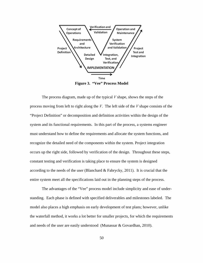
50
Figure 3. “Vee” Process Model
The process diagram, made up of the typical V shape, shows the steps of the
process moving from left to right along the V. The left side of the V shape consists of the
“Project Definition” or decomposition and definition activities within the design of the
system and its functional requirements. In this part of the process, a systems engineer
must understand how to define the requirements and allocate the system functions, and
recognize the detailed need of the components within the system. Project integration
occurs up the right side, followed by verification of the design. Throughout these steps,
constant testing and verification is taking place to ensure the system is designed
according to the needs of the user (Blanchard & Fabrycky, 2011). It is crucial that the
entire system meet all the specifications laid out in the planning steps of the process.
The advantages of the “Vee” process model include simplicity and ease of under-
standing. Each phase is defined with specified deliverables and milestones labeled. The
model also places a high emphasis on early development of test plans; however, unlike
the waterfall method, it works a lot better for smaller projects, for which the requirements
and needs of the user are easily understood (Munassar & Govardhan, 2010).

51
Spiral Process Model
The final model used by systems engineers is the spiral process model, presented
in Figure 4. Originally developed in 1968, the model was “intended to introduce a risk-
driven approach for the development of products or systems” (Blanchard & Fabrycky,
2011). Using the constant feedback provided by the “Vee” process method, the Spiral
model makes the process of requirements, design, and conception cyclical while adding
in a factor of risk. The need for risk analysis was the main component lacking from the
“Vee” process model and the basis for what drove the design of the spiral model. The
Figure 4. Spiral Process Model
spiral has four separate phases: Planning, Risk Analysis, Engineering, and Evaluation
(Munassar & Govardhan, 2010). The phases allow the design team for any prototype
development to continually walk through each process in the chain to ensure it meets all

52
the desired specifications. Based on the spiral design, the angular component represents
the progress of the design, while the radius of the spiral represents cost (Munassar &
Govardhan, 2010). At the end of each cycle, prior to moving to the next cycle, the design
team is mandated to evaluate their prototypes and alternatives, solicit suggestions and
changes from stakeholders, evaluate the inputs, and decide what changes to make.
Software developers and design teams agree the spiral model’s focus on risk
analysis is an advantage, that it works well for large and mission-critical projects, and
that it is iterative and extremely flexible. Disadvantages of the model include that it’s
costly to use, requires highly specific expertise, is incompatible with smaller projects, and
exquisitely dependent on the risk analysis phase (Munassar & Govardhan, 2010). Even
with its liabilities, the process quickly became the model of choice for design teams
walking through a cradle-to-grave design process (Blanchard & Fabrycky, 2011).
Choosing a Systems Engineering Model
After weighing the options, the design team decides which model best fits the
requirements and problem given to them. Each model has a specific set of advantages
and disadvantages and is made for certain types of problem sets. While the waterfall
model, “Vee” model, and spiral model are the most commonly used models within
systems engineering, each can be manipulated to meet the needs of the project
specifications and design team. Based on the type of tool and design required with each
part of the research described in this document, a specific model was identified and
followed until the completion of the design.

53
Systems Engineering Properties: “-ilities”
At the turn of the 20th century, when automobiles, electricity, and the airplane
were all at the forefront of the technological innovations, these inventions were “designed
for first use.” This means that the primary aim of the designer was to create an invention
that would fulfill its primary function at the time it was first turned on and little thought
was given to the indirect consequences of the invention in the future (de Weck, Roos, &
Magee, 2011). This time period was referred to as the epoch of great inventions and
artifacts (de Weck, Roos, & Magee, 2011).
As the innovations and inventions became more common, the focus of the
designers began to change, leading to the epoch of engineering systems. During this time
period, designers placed greater emphasis on understanding the systems engineering
properties that affected the long-term utility of their products (de Weck, Roos, & Magee,
2011). The change in thinking was because the customer began to understand the
concept of downstream life-cycle outcomes and therefore began placing more
responsibility on the designers of the product (Blanchard & Fabrycky, 2011). This
increase in responsibility led designers to consider the product’s systems engineering
properties, commonly referred to as -ilities, more carefully. A technical definition –of
ilities has been stated:
… The desired properties of systems, such as flexibility or maintainability, that
often manifest themselves after a system has been put to its initial use. These
properties are not the primary functional requirements of a system’s performance,
but typically concern wider system impacts with respect to time and stakeholders
than are embodied in those primary functional requirements. The -ilities do not

54
include factors that are always present, including size and weight. (de Weck,
Roos, & Magee, 2011)
The properties most commonly analyzed in products today include: quality, reliability,
safety, flexibility, robustness, durability, scalability, adaptability, usability,
interoperability, sustainability, maintainability, testability, modularity, resilience,
extensibility, agility, manufacturability, repairability, and evolvability (de Weck, Roos, &
Magee, 2011). Each of these -ilities is specifically defined and can be analyzed through
different techniques; however, each -ility’s individual definition is highly dependent on
other -ilities within the list. The main -ility being discussed and analyzed within this
research is usability; however, the definition of usability requires the testing of product
quality, flexibility, durability, adaptability, interoperability, maintainability, testability,
manufacturability, repairability, and evolvability.
Usability
Usability, slightly different from operability, “deals with an individual’s ability to
accomplish specific tasks or achieve broader goals while “using” whatever it is that is
being investigated, improved, or designed — including services that don’t even involve a
“thing” like a doorknob” (Reiss, 2012). The analysis of usability relies both on the
performance of the product, and on the human factors required to operate the product.
Human factors are the “properties of human capability and the cognitive needs and
limitations of humans” (de Weck, Roos, & Magee, 2011). The usability of a computer
program would be zero for a group that had no idea how to use a computer, even if the
program is state of the art.

55
Usability is most commonly analyzed as an -ility for computer interfaces and
programs because there is a definite relationship between the program’s purpose and the
customer’s ability to properly use the program. Within computer program design,
usability analysis is normally broken into six different objectives or goals. The six
measured objectives include the product’s being (Preece, Rogers, & Sharp, 2007)
1. Effective to use (effectiveness)
2. Efficient to use (efficiency)
3. Safe to use (safety)
4. Of good utility (utility)
5. Easy to learn (learnability)
6. Easy to remember how to use (memorability).
The goals related to analyzing the usability of a product are normally operationalized as
questions to help provide an exact method of assessing the numerous aspects of the
interactive product and the customer experience. The more detailed the questions, the
more likely the designer is to find unforeseen problems within the design. Having a clear
definition and understanding of the different usability objectives helps the designer
develop the questions for the analysis.
Usability: Effectiveness
Based on the requirements identified at the beginning of the design process, the
effectiveness of the product determines “how good the product is at doing what it was
designed to do” (Preece, Rogers, & Sharp, 2007). If the designer correctly identified all
the requirements of the user in the beginning and was able to incorporate all those require-
ments into the design, the effectiveness of the product should be simple to determine.

56
Usability: Efficiency
The efficiency of the product is determined by the user’s level of productivity
once the product has been learned (Nielson, 1993). Within the definition of efficiency,
other -ilties like quality, flexibility, maintainability, and durability are subsequently
tested. This is because a product that is hard to maintain or a product that is of poor
quality will result in a lack of efficiency over time for the user.
Usability: Safety
Safety involves multiples tiers of ensuring the product is safe for the customer.
The first part of analyzing safety is determining whether the product will place the
customer into a hazardous or dangerous environment (Preece, Rogers, & Sharp, 2007).
For computer systems that are near hazardous areas like X-rays or chemicals, the
program should allow the user to access it remotely.
The second part of the safety analysis is determining whether the product causes
the user to carry out unwanted actions accidentally or the ease with which a customer can
make an error (Nielson, 1993). This normally occurs due to buttons being too close together,
toggles being too sensitive, or a lack of understanding of all the abilities of the product. By
ensuring proper safeguards are in place to minimize mistakes and quell any fears by the
customer, the safety of the product is addressed (Preece, Rogers, & Sharp, 2007).
Safety can involve analyzing other -ilities including durability, interoperability,
repairability, and flexibility. Understanding the dependency on each of the -ilities will
make for a better quality product overall.

57
Usability: Utility
Utility refers to the “extent to which the product provides the right kind of
functionality so that users can do what they need or want to do” (Preece, Rogers, &
Sharp, 2007). The difference between low utility and high utility is based on the user’s
ability to complete everything needed within the task using the tool provided or needing
to use other tools and devices to complement the product to solve the problem. By
testing utility, one is also looking at flexibility, adaptability, and evolvability.
Usability: Learnability
Learnability is the ease with which the user is able to learn to use the product
(Preece, Rogers, & Sharp, 2007). When designers are looking at a program to design,
they ensure the system is easy enough for the user to have the ability to begin doing
productive work within a reasonable amount of time without extensive, in-depth training
(Nielson, 1993). Learnability is ensured through quality assurance practices by the
owners and the design companies, as well as iterative testing with those who will use the
product.
Usability: Memorability
Finally, memorability deals with the user’s ability to retain the training and skills
necessary to still effectively use the product. If a user is able to return to the system after
an extended period of time and immediately begin using the product efficiently, then the
product is said to have high memorability (Nielson, 1993). A usable system has a higher
memorability if continuous training is not required to stay proficient on the system or
product. In a way, memorability tests quality, testability, interoperability, and agility. By

58
testing a product’s usability through the given objectives, a researcher is able to analyze
how usable a product is for the crowd for whom the product is most intended.
Summary
This literature review provided an overview of the existing literature and current
research relating to the key topics of this research effort. The topics described in this chapter
included a background on the traditional manufacturing process and a deep dive into the
development of additive manufacturing. This led into an introduction of the military
applications currently utilizing additive manufacturing. It closed with a discussion of
systems engineering methodologies, as well as defining usability when it comes to the value
of a manufactured product. The following chapter presents the use of a semantic differential
scale survey to measure usability and determine the value of additively manufactured
products for use in military operations.

59
III. Methodology
Chapter Overview
This chapter provides the methodology used in this research effort. The research
took place in two steps or phases. The first step was identifying areas within engineering
operations that have potential to be made more efficient through the use of a specially
designed, additively manufactured part. Utilizing a systems engineering design
approach, each part requirement was identified and a prototype was created for the use of
the study participants. Once the first phase was finalized, the second phase involved a
semantic differential survey designed to measure the actual usability of the printed part.
Results from the survey to determine whether measuring usability can act as a proxy for
determining the value of additive manufacturing within military operational units are
analyzed in Chapter IV.
Systems Engineering Design Methodology
For each part identified and designed during the research, the evaluation of all
common systems engineering models allowed for the best process to be chosen specific
to the requirements and the desired end-product. In the end, the spiral model, seen in
Chapter II and in Figure 5 below, was determined to be the best fit for each of the parts
being designed. The model’s focus of calculating risk suited the intent of creating a more
efficient design for the end user; and allowed for an iterative design-and-testing process
to weed out unforeseen flaws within the design or requirements.
As this chapter continues, each step within the spiral model will be discussed. In
regard to each specific part designed and printed, Chapter IV will discuss how the design

60
Figure 5. Spiral Process Model
process required stepping through the design drivers, constraints, functionality needs, and
different prototype designs multiple times to address unforeseen challenges. One
difference between the spiral model and the Vee and waterfall models is that the spiral
model dictates the use of prototypes within the iterative design process. The other
models do not require prototypes and focus more on the conceptual design phases
(Blanchard & Fabrycky, 2011). The ability of the spiral model to identify unforeseen
challenges and provide a framework for a work around is a fundamental necessity to
enable the performance of this research.
Overall, each of the steps within the systems engineering model, or whole life
thinking approach, plays a critical role in incorporating the “life cycle” mindset of all

61
systems engineering designs. Through the creation of a culture that thinks holistically,
designs and problem solving approaches become more adaptable than before, thereby
allowing for the improvement of processes and lowering life cycle costs (de Weck, Roos,
& Magee, 2011). As this section walks through the different components of the systems
engineering model, it is important to realize that while the context of interest for this
research is additive manufacturing, the model can be adapted and implemented in many
types of design practices and problem-solving approaches. Within this chapter, each
design step is discussed in broader terms, to provide a comprehensive understanding of its
importance. Chapter IV incorporates the implementation of the design methodology into
the identification, design, printing, and testing of the additively manufactured parts and
tools. The important thing to remember is that the overall systems engineering model
hinges on identifying a majority of the criteria in the beginning, having constant
communication throughout the process, and cooperation among the stakeholders through
each design iteration to accomplish the goal of providing the best possible product in the
end.
Requirements and Design Constraints
The most important step at the beginning of the design process is to ensure it
starts out on the right foot. This is done through the development of specific requirements
from the user. These requirements identify exactly what the end-product is supposed to do
when it comes to solving the problem or meeting the objective. The basics of a
requirement include the actual need of the user, what the product to is intending to
accomplish for the user, and what initial design constraints may factor into the design of

62
the problem. Many users can’t differentiate between an actual need and a requirement
because they are very similar.
To begin, a need or want is simply a broad definition of the overall requirements:
the high-level description, “30,000-foot view”, etc, of the problem without identifying
any specifics. Examples of a need or want include:
The football team needs to get better.
The expanding family wants a house.
The environmental department at a school needs something to securely hold and
shake their glass jars for experiments.
All of these identify an overall goal, but do not address any specifics. This is because the
need addresses only the high-level task.
The next level, which is the identification of the requirements, is more specific.
Requirements delve into the “what” the product must do to accomplish the need, as in the
following examples:
To get better, the football team must acquire a top 30 recruiting class, state-of-the-
art facilities, and depth at key lineman and skill positions.
The expanding family is in need of at least a 3-bedroom, 2-bathroom home with a
2-car garage and fenced backyard for their dog.
The agitator has to carry 4 glass bottles, the necks of the bottles are 3 inches in
diameter, and the unit will spin at 30 revolutions per minute instead of shaking.
Each of these specifics falls under the broad “need,” and each plays an important role in
the overall design of the product by providing specificity. The sooner requirements are
agreed upon by the user and designer, the more smoothly the project will go. Some
63
projects are hindered by requirements that increase during the design’s evolution, causing
delays and frustrations to both the user and the designer.
Even with specific requirements, every project has design constraints that limit
the design in some manner. Clear constraints can be identified quickly and up front in
initial meetings; however, more often than not, constraints are found as the design
progresses and prototypes are tested. Design constraints can range from material type,
color, size, placement, or any other factor that affects the design in some manner. While
constraints do limit the design, a thorough identification and consideration of all
constraints makes for a better product for the end-user.
The foundation for a smooth design and implementation process starts with a
proper analysis of the user’s need, all the requirements, and any constraints limiting the
design. From there, the designer and builder move on to the project’s risk analysis and
the design, construction, and testing phases of the process.
Risk Analysis
Risk analysis is done throughout the project, but it is even more important prior to
the start of the initial design cycle. Risk is defined as the “potential that something will
go wrong as a result of one event or a series of events” (Blanchard & Fabrycky, 2011).
Through the use of certain analysis tools, like discrete event simulation (DES) and
control theory, certain risks can be investigated and mitigated (de Weck, Roos, & Magee,
2011); however, not all risk can be mitigated within a project. There are four basic types
of risks associated with a project (Blanchard & Fabrycky, 2011):
1. Technical Risk: This risk is associated with engineering designs and specific
performance requirements. When constructed, the owner is taking the risk that

64
the contractor is technically capable of providing a usable product. If the designer
contracts out certain designs, then the designer is taking the risk that the designs
will be technically sound and meet all performance requirements. These risks are
ameliorated through design checks, bonding requirements, and experience levels
that ensure specific performance and technical requirements are met.
2. Cost Risk: For any project, there is always a risk that the costs will exceed the
original amount that was bid or estimated. Depending on the type of contract, this
risk could be more to the owner or to the contractor. Detailed plans and cost
estimates are built prior to the project start to mitigate any possible cost overruns.
3. Schedule Risk: Any deadline runs the risk of exceeding the projected completion
date. Contractors can be pressed to not go over their completion date through
incentives or delay penalties written into the contract. Detailed schedules with
Gantt charts and task lists are created to help a project stay on schedule.
4. Programmatic Risk: In a large organization, this type of risk is much more
prevalent. This is the risk of certain events imposed on the project/program,
which are a result of external influences. Either from leadership, external supply
factors, or any other outsides influences, this type of risk can be the most
unforeseen and challenging to plan for (Blanchard & Fabrycky, 2011).
In the end, risk analysis is an identification-and-mitigation process for the risks assumed
to be the most prevalent surrounding a project. Good project managers, designers, and
builders construct Risk Management Plans (RMP) to document the ways they go about
mitigating certain risks. Most RMPs also include a broad plan identifying what the
project manager would do in the event certain risk events took place on their project site.
65
Design/Building – Iteration #1, 2, 3…
A project may include numerous design-and-building processes because the spiral
model allows for prototypes to be passed across design and testing phases multiple times
until a useful product is created and all requirements are satisfied. Within the design-and-
building process, requirements and constraints are taken into account and a product is born.
The first model may look nothing like the final product, but the iterative process stepping
through the design and testing phases allows the designer to create a product and test it for
the user and designer to visually inspect. Once the designer makes any changes from the
previous testing cycle and finishes the iterative design , it is tested once again.
Testing – Iteration #1, 2, 3…
Following any design-and-building process, the testing phase ensures the product
meets the requirements identified within the first step. During this phase, the user and the
designer are able to see the prototype of the product in use. Sometimes visualization of
the actual designed product can result in additional requirements and constraints on the
project due to unforeseen visual or functional problems with the prototype. A part that does
not pass the testing phase is sent back to the design-and-building phase for modifications.
Within the testing phase, the viability of the product must also be verified. For
this research, the process to accomplish this step will be determining the usability of each
product identified and designed. The overall method for verification will be discussed
further in this chapter, while the verification results will be outlined in Chapter IV. All of
the user’s technical and functional specifications must be met for the design to pass the
testing phase and move on to the final handoff and integration.

66
Final Handoff, Integration, and Maintenance
Once through the testing phase, products reach the final handoff and integration
phase. This is very different for all products, as some may just be handed to the customer
and other products may go to a manufacturer for production. Either way, the customer
receives a useable product that must be integrated into his processes. This may involve
training and analysis of existing operations, and requires ensuring that procedures are in
place for its maintenance and care.
Each of these steps, from the identification of requirements to the implementation
and maintenance of the product, is essential to the “life cycle” mindset of systems
engineering design. Thinking holistically can cause designs to become more flexible and
adaptable than before, allowing for improvement of processes and lowering life cycle
costs (de Weck, Roos, & Magee, 2011). This systems engineering design process can be
adapted and implemented into the analysis and thinking of all design practices, to provide
a more efficient model for product development.
Systems Engineering Application
Within this research, the development of useful products capable of solving the
needs within today’s Air Force becomes more streamlined and efficient due to the
successful use of the systems engineering design methodology. Through the
implementation of the spiral model, the research specifically targets unique applications
within the engineering community to provide possible solutions through the use of
additive manufacturing. By seeking out applications, identifying the unit’s specific
requirements, conducting a comprehensive risk analysis, and then working to design,

67
print, and test a successful tool, the research looks to validate the ability of additive
manufacturing technology to provide solutions to unique challenges in the current
resource limited environment. With the systems engineering design methodology
described above, the actual tools used within the research design process will now be
examined further.
Materials and Equipment
The design process itself requires several different tools and pieces of equipment
to ensure an efficient product in the end. For this accounting of this research to be
thorough and repeatable, each tool and piece of equipment used within the research is
identified and described below.
Solidworks
The design of the tools and jigs during the initial design stages utilized Solidworks®
Computer Aided Design (CAD) software. The tutorial within the program is extremely
easy to step through and even basic users can design simple shapes and objects after
completing the how-to videos. When compared to other design software, the Solidworks®
program is easily the simplest to use, especially due to its ability to convert the .SLDWKS
file into an .STL file, which is the file type required for each of the AM printers. The file
type .STL is used by a majority of 3D printers and is the reason why Solidworks® is one of
the main programs used by most additive manufacturing firms. Other types of software
include AutoCAD®, Google® Sketchup, and other proprietary programs.
68
Measuring Tools
For measurements and dimensions during the design process, generic calipers and
measuring tools were used. Standard dimensions, rather than the metric system, were
used during the design process; however, Solidworks® and all 3D printing software have
the ability to switch between U.S. customary/standard units and the metric system units
in order to suit the preferences of the user.
Additive Manufacturing Equipment
The 3D Systems® ProJet™ 3500 and ProJet™ 1500 additive manufacturing
machines were used as the main printers for the tools and jigs printed during the research.
The 1500, seen in Figure 6, is a film transfer photopolymer machine which uses
photopolymer plastic material with ultraviolet (UV) curing inside the printer. The printer
uses the same plastic material as both the main printing material and the support structure
material. Because the support structures were of the same material, they tended to
obstruct the intended design of the product and required more-involved post processing.
The nominal build area for the printer is 10 in × 7 in × 7 in; however, prints tended to fail
approximately 0.5 in from the edge of the print area. While the 1500 did allow for basic
AM techniques to be learned, its print unreliability, large tolerances, and outdated
technology hindered the speed of data collection in the beginning.

69
Figure 6. ProJet™ 1500 Printer, Opened to View Printing Bed (right)
The ProJet™ 3500, seen in Figure 7, is a Multijet printer which passes a heated
material through multiple print heads to build the object layer by layer. It is a newer
printer and much more reliable than the ProJet™ 1500. The 3500 utilizes a clear, liquid
polymer as the main print material and a wax-based substance as the support material,
which melts off during post processing of the product, allowing for less post processing
and more complex designs. The nominal print area for the 3500 is 11 in × 8 in × 8 in.
Figure 7. ProJet™ 3500 HD Max Printer

70
Post Processing Equipment
Post processing equipment used for prints created in the ProJet™ 1500 is much
different from what is used for prints coming from the 3500. The two equipment items
used to post process all prints created within the ProJet™ 1500 are the solvent wash bed
(Figure 8) and the UV curing lamp cabinet. The only post processing equipment needed
for the ProJet™ 3500 is a ProJet™ Finisher oven, seen in Figure 9, which cures the print
at ~70° C (~158°F). The oven melts the support material wax from the print, leaving the
solidified print behind.
Figure 8. ProJet™ Solvent Washing Basin
Procedures and Processes
Now that the overall systems engineering process has been clearly defined, and
the tools and equipment used within this specific research identified, the actual process of
this specific research can be discussed. Through the implementation of the systems
engineering spiral model and the use of additive manufacturing technology, this research
seeks to identify specific applications for the design, printing, and testing of additively
manufactured solutions. By meeting the needs of the end-user, the research looks to
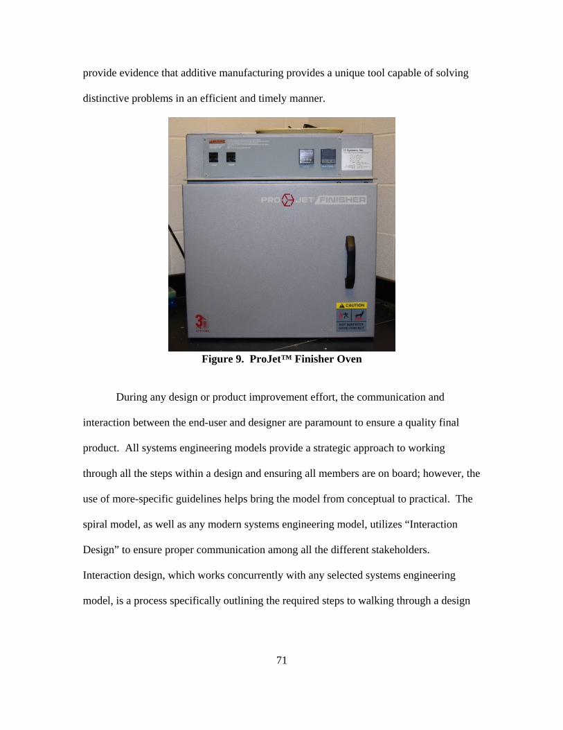
71
provide evidence that additive manufacturing provides a unique tool capable of solving
distinctive problems in an efficient and timely manner.
Figure 9. ProJet™ Finisher Oven
During any design or product improvement effort, the communication and
interaction between the end-user and designer are paramount to ensure a quality final
product. All systems engineering models provide a strategic approach to working
through all the steps within a design and ensuring all members are on board; however, the
use of more-specific guidelines helps bring the model from conceptual to practical. The
spiral model, as well as any modern systems engineering model, utilizes “Interaction
Design” to ensure proper communication among all the different stakeholders.
Interaction design, which works concurrently with any selected systems engineering
model, is a process specifically outlining the required steps to walking through a design

72
or product improvement. The steps of interaction design include the following (Preece,
Rogers, & Sharp, 2007):
1) Identify needs and establish requirements for the user experience.
2) Develop alternative designs that meet those requirements.
3) Build interactive versions of the designs so that they can be communicated
and assessed.
4) Evaluate what is being built through the process and the user experience it
offers
Needs Identification
Certain product attributes make it advantageous for production using AM
processes. These include low-volume production numbers, customizability of the
product, and flexible designs. Tools and products already within the CE inventory can be
rapidly redesigned using AM to reduce material usage, make the tool more efficient
overall, and be ready for any “just in time” applications. Additionally, AM can be used
to design and print jigs and specialty parts needed to solve current CE frustrations. First
one must identify processes within the CE shops that might be made more efficient
through the redesign and printing of an original tool. The design process begins by
determining exact requirements of the part, possible constraints that limit the design, and
the end performance or technical result needed by the user.
Design Process
Once the requirements have been identified, the design process begins. The
Solidworks® tutorial gives explicit instructions for creating shapes, cutting holes, and
designing any product. After opening the Solidworks® design software, one must select

73
U.S. standard dimensions or metric system measurements for the design. Once the initial
design is completed in Solidworks®, it is saved as a .STL file, the format required for the
AM printer. The icon to save a design as a .STL file is located under the “save as” function
within Solidworks®.
Product Printing
The saved .STL file is loaded into the printer software on the connected laptop.
Based on the printer’s settings, this can also be done remotely if the printer is connected
to a network. The diagnostics of the printer and the print polymer levels are tested prior
to starting a print. The diagnostic makes a reliable print more likely; checking the levels
guards against an interrupted job.
Product Post Processing
When the 3D Systems® ProJet™ 3500 finishes printing a design, the print plat-
form is removed from the printer and placed in a freezer for 5~10 minutes. The freezer
separates the build platform from the print and prepares it for the next stage of post
processing. The build platform is removed from the freezer and carefully separated from
the print, which is placed inside the ProJet™ Finisher oven at ~70° C (~158 °F). The
print needs to be rotated every 15~30 minutes until support materials have melted away.
Soaking the print in ethanol for ~5 minutes removes final traces of waxy residue from the
printed piece. If the printed piece has any moving parts, air tool grease or WD-40® does
an excellent job of lubricating the moving parts. Once the waxy residue is gone and parts
are sufficiently lubricated, a Dremel® tool can be used to sand down any remaining
rough edges.

74
Product Testing
After printing and post processing, the tool or part is actually tested in a training
environment. The test must be conducted thoroughly and designed to test both the utility
and the durability of the product—the product must complete its intended task and, unless
it is sacrificial by design, survive intact. All initial requirements for the product must be
analyzed in a scenario simulating an actual operational setting. If any test is failed or if
changes to the design are needed, the product’s design is altered and the process restarts.
Only after the final product is handed over to the user can the design be considered
complete. Following completion of the design and testing of the tool, a usability survey
is given to the user to evaluate the actual usability of the product.
Usability Survey
Usability, as defined by (Reiss, 2012), “deals with an individual’s ability to
accomplish specific tasks or achieve broader goals while ‘using’ whatever it is a person is
investigating, improving, or designing – including services that don’t even involve a
‘thing’ like a doorknob.” Based on the six specific factors defining usability, a 19-
question survey was developed and given to the user after the final printed part was
handed over. The survey includes six different objectives or components defining the
overall concept of usability. Each goal is operationalized using a semantic differential
scale, which utilizes opposite terms along a scale to rate the user’s reaction to the product
(Nielson, 1993). Based on the scale and the rating for each question, overall user
satisfaction with the product determined its usability. The final rating for subjective
satisfaction was calculated from the average overall rating for each objective. The

75
usability objective title was hidden on the survey given to the users and the questions
below were randomized:
1) Quality
a. Overall reaction to the new tool/part
i. Useless 0 1 2 3 4 5 6 7 Useful
ii. Difficult 0 1 2 3 4 5 6 7 Easy
iii. Fragile 0 1 2 3 4 5 6 7 Durable
2) Effective to use (effectiveness)
a. For its desired purpose, the size of the printed part is _________:
i. A Hindrance 0 1 2 3 4 5 6 7 Optimal
b. The installation of the part is _______:
i. Easy 0 1 2 3 4 5 6 7 Difficult
c. The printed part could be effectively used in ____________:
i. Training Only 0 1 2 3 4 5 6 7 Fully Operational Uses
d. Iterative testing process _______ additional unforeseen problems
i. Created 0 1 2 3 4 5 6 7 Solved
3) Efficient to use (efficiency)
a. Compared to original process, the new tool makes the process:
i. Less efficient 0 1 2 3 4 5 6 7 More efficient
b. Due to the part being printed, ______ specialized tools are needed for
installation:
i. Several 0 1 2 3 4 5 6 7 None
c. Tasks when using the tool can be performed in a straight-forward manner:

76
i. Never 1 2 3 4 5 6 7 Always
4) Safe to use (safety)
a. Overall safety of product:
i. Dangerous 0 1 2 3 4 5 6 7 Safe to Use
5) Having good utility (utility)
a. Aside from the primary purpose, there are _______ other possible uses for
tool:
i. No 0 1 2 3 4 5 6 7 Multiple
b. At home station, ___________ other uses within your flight exist for 3D
printed solutions to improve operations:
i. None 0 1 2 3 4 5 6 7 Multiple uses exist
c. In deployed environment, ____________ other uses within your flight
exist for 3D printed solutions to improve operations:
i. None 0 1 2 3 4 5 6 7 Multiple uses exist
6) Easy to learn (learnability)
a. Learning to use the tool was:
i. Difficult 1 2 3 4 5 6 7 Easy
b. Discovering additional uses for the tool is ___________:
i. Difficult 1 2 3 4 5 6 7 Easy
c. A ___________ amount of Supplemental Reading/Training Required prior
to using the tool:
i. Time Intensive 0 1 2 3 4 5 6 7 minimal
7) Easy to remember how to use (memorability)

77
a. Retraining needs to be done __________ to stay proficient on the tool:
i. Often 0 1 2 3 4 5 6 7 Never
b. Advanced technical skills required to use the tool:
i. Expert 0 1 2 3 4 5 6 7 Basic
The Internal Review board exemption package for the survey can be found in
Appendix A.
Data Analysis
To ensure proper evaluation and analysis of the survey results, each designed part
must have at least two surveys filled out by different users. The median survey results
and standard deviation of the overall results to the questions were then tested to prove the
questions consistently garner responses that accurately portray the authentic usability of
the product. These calculations are discussed further in Chapter IV.
Summary
In conclusion, the research being conducted with this thesis took part in two
phases. Phase 1 determined a need, developed a design, and built and tested a product.
This hands-on approach provides a proof of concept for the application of designing and
printing tools and jigs within a CE squadron. Phase 2 acquires and interprets more-
qualitative data through the use of a semantic differential scale “usability” survey. The
intention of the survey, taken by at least two different users for every printed item, is
intended to prove the usability of the actual product. By assaying user opinions of the six
components of usability, the results of the survey will evaluate examples of AM as a

78
technology to provide specialized tools capable of providing unique solutions to some
unsolved problems facing the Air Force today.

79
IV. Analysis and Results
The preceding chapter presented the research methodology utilized within this
thesis. The methodology primarily outlined the process within Phase 1 for designing a
part using a systems engineering methodology and printing the part using additive
manufacturing technology. The processes involved in printing an additively manufactured
part were described in detail, as was the semantic differential survey used to determine
the viability of additive manufacturing within the Air Force civil engineering career field.
The design methodology as described in Chapter III was conducted between January and
December of 2015. Subsequently, the “Usability” survey was conducted during the
months of November and December 2015. The results of each of these phases and an
analysis of these results are presented in this chapter.
Additively Manufactured Part Designs
This section covers the AM applications identified within the research. Overall,
the identification of six separate parts is discussed, including an in-depth analysis of each
design, printing, and testing process. Additionally, the usability results from each
corresponding survey are analyzed. Overall, each part proved unique it its challenges and
design criteria, and the results acknowledge the general usefulness of the designs and the
implementation of the additive manufacturing process within CE operations.
EOD Bracket Design
The design of the Explosive Ordinance Disposal (EOD) bracket evolved from the
career field’s need for a piece of equipment to attach specific hazardous material
(HAZMAT) sensors to the arm of their main unmanned ground vehicle (UGV). EOD

80
technicians utilize the Northrop Grumman Remotec® UGV, for hazardous duty
operations, including field inspection and detonation of explosive devices (Figure 10).
The primary focus of the AM applications discussed in this research is localized to the
robot arm assembly (Figure 10), which is specified in detail using measurements,
drawings, and photographs. 3D Printing Makes Explosive Headway at AFIT and 3D
Printing Handbook: Product Development for the Defense Industry, both provide details
about EOD’s mission, the background of the bracket’s requirements, and in-depth design
analysis of the different prototype iterations.
Figure 10. Northrop Grumman Remotec® Unmanned Ground Vehicle (left)
(Cooper, 2011). Arm Assembly on the Northrop Grumman Remotec® UGV (right)
During the initial requirements meeting, the main purpose and need for the
bracket was described as a quick attachment allowing the EOD technicians to switch
among three sensors. Each sensor was used for a separate and specific type of chemical,
biological, radiological, nuclear, and explosive (CBRNE) threat. EOD technicians at

81
Wright–Patterson AFB typically utilize four different sensors (Table 2) during their
operations.
Table 2. Summary of Sensors
Sensor Function Dimensions (in) (width × depth ×
height)
Weight (lbs)
Victoreen® Fluke® Biomedical 451P
Radiation survey of environment 4 × 8 × 6 2.4
MultiRAE ® PGM® 6248
Multi-threat monitor for radiation and chemical detection
3.8 × 2.6 × 7.6 1.9
identiFINDER® R400
Detects, locates, measures and identifies radionuclides and isotopes
9.8 × 3.7 × 2.9 3.2
Smiths Detection® LCD 3.2E (aka JCAD M40)
Real-time detection of chemical and toxic substances
4.3 × 7.1 × 2.0 1.15
Most EOD operations utilize each sensor on an independent basis, so there was
not a specific design requirement to attach more than one sensor to the UGV. Since
sensors differ in dimensions, weights, and functions, as shown in Table 2, it was important
to understand which sensor characteristics comprise design constraints. The Victoreen®
Fluke® Biomedical 451P sensor (Figure 11) was used as the main target during the
prototype design—being the largest sensor it had the greatest depth requirement. Weight
was not a concerning factor during the initial prototype design. Based on the risk
analysis of the requirements and design, the EOD technicians were counting on the
bracket to securely hold each sensor on the robot. Any malfunction by the bracket could
put EOD personnel in harm’s way to retrieve the failed bracket and sensor; therefore, the
two most important requirements for mitigating the analyzed risk were (1) securing the
bracket to the robot, and (2) securing the sensor in the bracket.

82
As the design process kicked off, the initial design was a solid bracket that attached to the
robot using a bridge piece to be held by the anchor points and the robot’s rotating hook
(Figure 12). Walls on the four sides of the bracket would hold the sensors in place on the
robot. As this was the initial design, satisfactory attachment of the bracket to the robot was
the main consideration. Ensuring each sensor was secure on the bracket would come later
in the design. The first iteration did not make it to the printer because it was excessively large
and did not meet all requirements mandatory for the design to move forward. In iteration
2, the design team had more experience with the 3D printer and understood better how to
design a product to achieve the best results from the print.
Figure 11. Victoreen® Fluke® Biomedical 451P sensor
Figure 12. Anchor Points and Hook Attachment for Bracket on the EOD UGV
Iteration 2 evolved with the notion that an additively manufactured product is
weakest in the z direction (vertical). Knowing this and also understanding that the
bracket had to be built to secure the large sensors, iteration 2 tested the notion of printing
multiple parts that would be assembled prior to the printing process. Using squares
placed at standardized distances across the bracket, walls were designed to slide into and
out of the holes. This conceptually allowed the walls to be moved in and out based on

83
which sensor was being used in the operation. A large hole was also incorporated into
the design for the handle of the largest sensor. As it was the only sensor with a handle, this
hole could carry the sensor instead of requiring the bracket to secure the entire sensor on
top. The hole for the handle turned out to work and was continued in other iterations. On
the other hand, the concept of assembly turned out to be flawed due to tolerances of the
printer, which caused the walls to not fit correctly and not securely attach the sensor to
the bracket; thus, iteration 2 made it past only the printing phase.
Iteration 3 was an assembly in greater depth, based on the design of clips found
on suitcases and backpacks. The design tested the print material’s ability to bend before
locking the piece in place. The elasticity of the material proved to be too little—each
print snapped during assembly. Iteration 3 was scrapped prior to field testing. Failures
based on the assembly design, inspired a new concept that was discussed and integrated
into iteration 4.
The iteration 4 design recognized that additive manufacturing’s potential to
quickly and efficiently print parts and tools for unique situations did not exclude
fabricated components. Elastic bands, available at any retail or home improvement store,
were incorporated into the design of iteration 4. Using a base to attach the bracket to the
robot, 3 connection points were added on either side of the bracket to attach the elastic
bands and secure the sensors on the bracket. Only one piece had to be printed and the
elastic bands allowed for EOD technicians to quickly detach and switch sensors in a
matter of seconds. Iteration 4 was the first prototype taken to EOD for field testing. The
design was successful in that it secured the sensors to the bracket; however, the hook put

84
too much force on the bridge and cracked the bracket. Iterations 5 and 6 retained the elastic
bands and focused on strengthening the bridge for the attachment of the part to the robot.
Iteration 5 moved the bridge slightly lower and added material underneath it to
provide more resistance to the hook. Additionally, the design was refined to decrease use
of material. Unneeded sections of the bracket were cut out, thus requiring less material
for printing. The bridge again failed during the testing of iteration 5. For iteration 6 the
design team explored alternative methods for securing the bracket to the robot.
The method of securing the bracket to the robot had not changed since the
beginning of the initial design. This method was based on how the other EOD
attachments were connected to the robot; however, they were made of steel and had far
superior shear strength than the additively manufactured parts. The printed bracket was
much lighter than any of the other attachments, so the full force of the hook was
unnecessary to hold the bracket down. Using the same elastic bands being utilized to
secure the sensors, the new design called for attached tightly stretched band within the
interior of the bracket, ran it through a hole where the bridge used to be, and then
attached it to one of the connection points on the opposite side of the bracket. The
tightness of the band provided the needed strength to hold the bracket down, but also was
flexible enough to withstand the force of the hook on the elastic strap. This prototype
included a few other small modifications based on last-second needs from EOD. This
print tested successfully in the field and passed an operational test within a controlled
training scenario. Figure 13 shows the bracket being tested with the identiFINDER®
R400 successfully attached to the robot. A look at the progression from iteration 1 to

85
iteration 6 can be seen in Figure 14. Following testing, the bracket was handed over to
the EOD shop for use.
Multiple brackets were printed and given to the EOD shop for use in training and
operations. The design was also sent to multiple other EOD units across the country for
printing and use. EOD technicians quickly reported finding other uses for the bracket
within their training, and are continuing to look for ways to leverage their new tool and
Figure 13. EOD Bracket with IdentiFINDER® R400 Attached

86
Figure 14. EOD Bracket Design Progression (Six Iterations)
3D printing technology within their shop. In Figure , the bracket was set up to carry one of
the unit’s backpack sensors that is normally used to inspect Conex boxes for explosives.
This is important because the weight of the sensor was driving normal EOD operations
and requiring an EOD operator to carry the sensor in to inspect those units. Other units
Figure 15. EOD Bracket with Backpack Sensor Attached

87
found that they could attach multiple sensors to the bracket at the same time, as seen in
Figure 16. In the end, the overall design went through six major iterations and multiple
tests. The first prototype tested (iteration 2) required 551g of material and was extremely
bulky and heavy. In contrast, the iteration 6 design required 240g of material and proved
to be light and efficient. The design of the robot bracket took 10 months, mainly due to
logistics within the research; however, multiple iterations and designs were turned around
in less than 24 hours when the resources and time were available.
Figure 16. EOD Bracket with Two Sensors Attached
EOD Bracket Survey Results
The usability survey was given to the three EOD technicians who had the most
experience using the robot within the Wright–Patterson EOD shop. Their time in service
ranged from 4 to 8 years, and their ranks included airmen and non-commissioned officers
(NCOs). Each technician understood that the survey measured the usability of the
specific EOD bracket and was not based on any other experiences with 3D printing. The

88
results of the usability survey, shown in Table 3, are broken down by each component
and then aggregated into an overall score.
Table 3. EOD Bracket Usability Survey Results (n = 3 Responses)
Objective # of
Questions Evaluator Scores
High Low Mean Standard Deviation Quality 3 7 5 6.44 0.88 Efficiency 3 7 7 7.00 0.00 Effectiveness 4 7 3 6.50 2.82 Utility 3 7 3 5.78 1.86 Learnability 3 7 3 6.11 1.76 Safety 1 7 7 7.00 0.00 Memorability 2 7 5 6.67 0.82 Aggregate 19 6.44 1.28 90% CI Limits 7.00 4.80
As discussed in the methodology chapter, each survey question measured a
certain usability objective and the range of scores was 0 to 7. The EOD bracket received
a perfect score (7.0) for objectives dealing with efficiency and safety. Scores for the
aspects of usability, memorability and effectiveness were also close to perfect, averaging
6.67 and 6.5, respectively. The 6.67 memorability score echoes that the bracket might
require minimal retraining for members after an extended time away from the tool, and
the 6.5 effectiveness score mirrors one technician’s belief that the bracket is a bit more
useful in a training role than in an operational role. The two younger technician’s
viewpoints were not aligned with the more-experienced NCO, who scored the bracket
well for the memorability and effectiveness objectives.
The numerous iterations required to perfect the cracking bridge piece within the
part resulted in a lower quality component score of 6.44. The only quality question
receiving less than optimal scores was the durability component of the bracket. The final
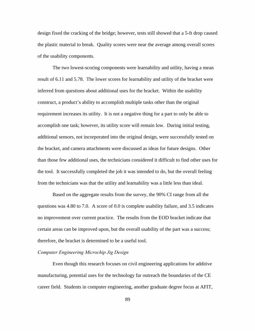
89
design fixed the cracking of the bridge; however, tests still showed that a 5-ft drop caused
the plastic material to break. Quality scores were near the average among overall scores
of the usability components.
The two lowest-scoring components were learnability and utility, having a mean
result of 6.11 and 5.78. The lower scores for learnability and utility of the bracket were
inferred from questions about additional uses for the bracket. Within the usability
construct, a product’s ability to accomplish multiple tasks other than the original
requirement increases its utility. It is not a negative thing for a part to only be able to
accomplish one task; however, its utility score will remain low. During initial testing,
additional sensors, not incorporated into the original design, were successfully tested on
the bracket, and camera attachments were discussed as ideas for future designs. Other
than those few additional uses, the technicians considered it difficult to find other uses for
the tool. It successfully completed the job it was intended to do, but the overall feeling
from the technicians was that the utility and learnability was a little less than ideal.
Based on the aggregate results from the survey, the 90% CI range from all the
questions was 4.80 to 7.0. A score of 0.0 is complete usability failure, and 3.5 indicates
no improvement over current practice. The results from the EOD bracket indicate that
certain areas can be improved upon, but the overall usability of the part was a success;
therefore, the bracket is determined to be a useful tool.
Computer Engineering Microchip Jig Design
Even though this research focuses on civil engineering applications for additive
manufacturing, potential uses for the technology far outreach the boundaries of the CE
career field. Students in computer engineering, another graduate degree focus at AFIT,
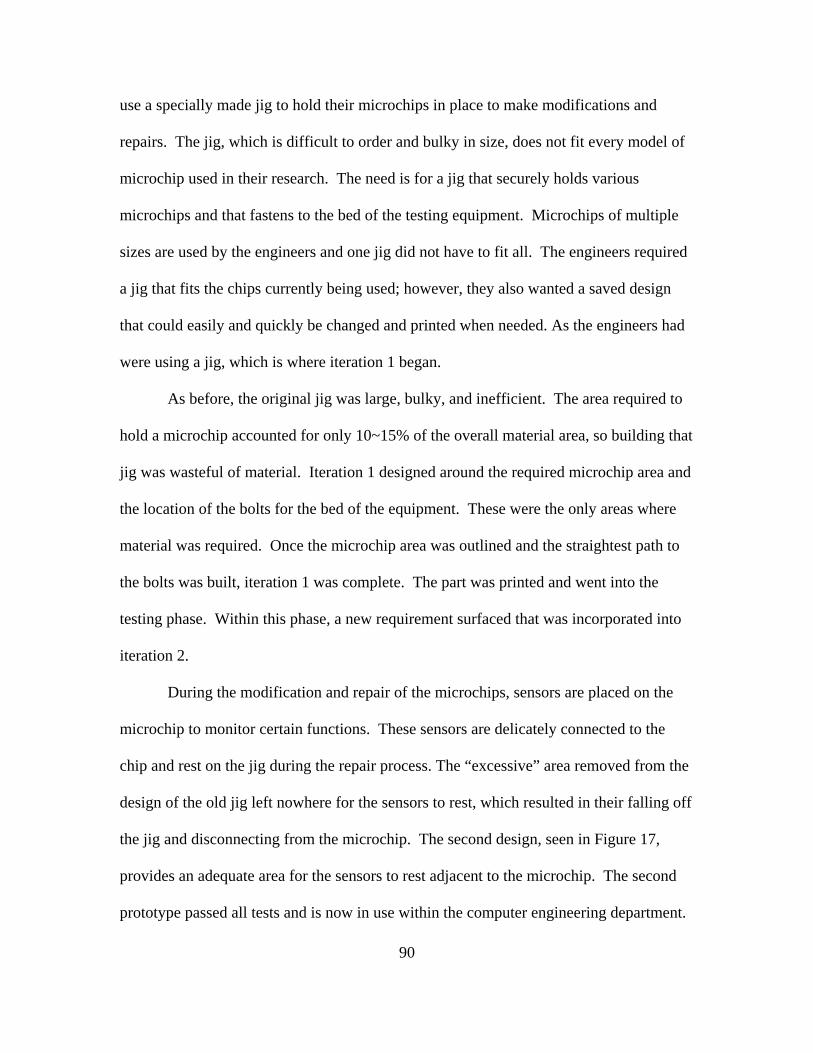
90
use a specially made jig to hold their microchips in place to make modifications and
repairs. The jig, which is difficult to order and bulky in size, does not fit every model of
microchip used in their research. The need is for a jig that securely holds various
microchips and that fastens to the bed of the testing equipment. Microchips of multiple
sizes are used by the engineers and one jig did not have to fit all. The engineers required
a jig that fits the chips currently being used; however, they also wanted a saved design
that could easily and quickly be changed and printed when needed. As the engineers had
were using a jig, which is where iteration 1 began.
As before, the original jig was large, bulky, and inefficient. The area required to
hold a microchip accounted for only 10~15% of the overall material area, so building that
jig was wasteful of material. Iteration 1 designed around the required microchip area and
the location of the bolts for the bed of the equipment. These were the only areas where
material was required. Once the microchip area was outlined and the straightest path to
the bolts was built, iteration 1 was complete. The part was printed and went into the
testing phase. Within this phase, a new requirement surfaced that was incorporated into
iteration 2.
During the modification and repair of the microchips, sensors are placed on the
microchip to monitor certain functions. These sensors are delicately connected to the
chip and rest on the jig during the repair process. The “excessive” area removed from the
design of the old jig left nowhere for the sensors to rest, which resulted in their falling off
the jig and disconnecting from the microchip. The second design, seen in Figure 17,
provides an adequate area for the sensors to rest adjacent to the microchip. The second
prototype passed all tests and is now in use within the computer engineering department.

91
Figure 17. Computer Engineering Jig, Iteration 2 Design
The printed jig and the CAD design, were handed over following final testing.
According to the requirements identified at the beginning of the design, the user is now
able to quickly change the needed dimensions of the jig and reprint the tool. The time
table for the actual tool, seen in Figure 18, from the identification of requirements to
handing off the part, was approximately 1 month. The next section discusses the results
of the usability survey evaluating the computer engineering jig.
Figure 18. Computer Engineering Jig in Operational Use

92
Computer Engineering Microchip Jig Survey Results
The computer engineering jig was used by only two members in the department;
both US Air Force Majors, and both took the usability survey. Their time in service
ranged from 13 to 15 years. The results, seen in Table 4, and discussion are found below.
Table 4. Computer Engineering Jig Overall Usability Results (n = 2 Responses) Objective # of
Questions Evaluator Scores
High Low Mean Quality 3 7 5 6.33 Efficiency 3 7 0 4.50 Effectiveness 4 7 5 6.50 Utility 3 4 0 2.67 Learnability 3 7 3 5.83 Safety 1 7 7 7.00 Memorability 2 7 7 7.00 Aggregate 19 5.53 90% CI Limits 7.00 2.80
The results from the usability survey for this jig appear to be anomalous when
compared to the results from the other printed parts. At first look, it is difficult to
understand the extreme variation in scores; however, when analyzing relevance of the
questions to the job description of the personnel using the part and taking part in the
survey, a clearer picture emerges of why the results are so significantly different.
Engineers with an Air Force Specialty Code (AFSC) designation of 62E are re-
ferred to as developmental engineers, and job descriptions in the developmental engineering
career field differ completely from those within civil engineering. Developmental engineers
typically work in research and development areas and are not subject to many deployments
or operational taskings. Thus, several questions within the usability survey that were

93
directed toward deployments or operational job duties are not relevant to the experience
and duties performed by those taking the survey for the computer engineering jig.
The specific objectives most affected by the difference in job duties include
efficiency, utility, and learnability. Since the part is used within a larger machine for
microchips, the installation of the printed tool still requires the use of other equipment to
ensure proper placement. This resulted in the efficiency metric being skewed by low
answers for the one question.
The utility and learnability of the part were both low due to the specific questions
being asked. The tool was printed for a specific purpose and could not be used for
anything else. Furthermore, because the tool was designed for a research and
development-based career field, applications within their job for 3D printing were not
applicable at home station or within a deployed environment. When the participant was
asked about giving the score of a 4, they answered based on the assumption that 4 would
be interpreted as “Not Applicable” or “not good or bad.” Based on the findings, the
specific questions led to low scores for utility and learnability. AM’s ability to design a
product specifically for one purpose resulted in a decrease in the utility of a part. This
decrease, while it does not mean a poor product, it does skew the actual usability results
as a whole. A lesson here is that future surveys should include a “Not Applicable (N/A)”
choice to allow a person taking the survey can answer in a more reliable manner without
skewing the overall results.
As the objectives with skewed results can be disregarded, the other four usability
components scored well. Markdowns for effectiveness came from the user who regarded
the size of the part not optimal and thought the design process should have identified the

94
unforeseen problem in the first design. When interviewed about the scores, the user did
not answer how the jig was imperfect, but did concede that the problem was an additional
requirement that was not identified during the initial design process. Regarding the size
of the part being a hindrance, the amount of material used in the final design was 60%
less than for the original part, and product weighed almost 43% less. The design team
could find no way to meet all the requirements and shrink the part any further.
Even with the mismatched questions, the jig’s mean score was 5.53, which
identifies an improvement in usability. Due to the small sample size, the variance and
other statistical measures are greatly multiplied and end up skewing the end results. The
90% CI range for the overall usability score is 2.8 to 7.0. This is a larger gap than any
other printed part within the research, so the research concludes that while the literal
result implies a slightly better of “neither usable nor nonusable” product, a more-
qualitative interpretation of the overall results clearly identifies a “completely usable
product.” In the end, the product was deemed extremely useful based on the stakeholder
being pleased with the design and they are currently using it for their computer
engineering operations.
Utility Pipe Inspection Autonomous Vehicle Bracket Design
Among the numerous innovations being researched at AFIT, another researcher is
looking into the possibility of being able to conduct underground utility infrastructure
inspections through the use of completely autonomous vehicles is intriguing for many
aspects within civil engineering. Similar to the current condition of aboveground
infrastructure, much of the infrastructure below the surface is just as degraded and well
beyond its useful life. The ability to conduct accurate inspections and then pinpoint

95
where the next failure will occur has the potential to mitigate millions of dollars in
contingency spending for broken water mains and utility lines. Due to the nature of this
research, the researcher designed a vehicle, seen in Figure 19, to be placed inside utility
pipes and carry out inspections based on specific inspection parameters. Several pieces
of equipment designed to go on the robot were more difficult to attach than originally
expected. The lightweight and customizable benefits provided by additive manufacturing
enabled the researcher to continue their research without compromising their vehicle due
to the equipment limitations. The parts designed and printed for the autonomous vehicle
project are discussed in the following sections. An overview and interpretation of the
usability survey results follow the discussion of the design for the autonomous vehicle
parts.
Figure 19. Autonomous Utility Inspection Vehicle

96
Front Camera Bracket Design
The first piece of equipment designed for the autonomous utility inspection
vehicle was a dual bracket intended to go on the front of the vehicle and hold both a light,
detection, and radar (LIDAR) sensor and a digital video camcorder. The Hokuyo®
URG-04X-UG01 LIDAR sensor, conducts a 270° scan of the pipe and its programmed
algorithm detects any anomalies. Prior to the additive manufacturing bracket design,
attaching the front LIDAR sensor required running a plastic cord (cable tie) through holes
in the base plate of the vehicle, seen in Figure 19; however, the geometry of the sensor
caused it not to sit exactly level, which made it difficult to orient the sensor perfectly level
with the vehicle and limited the reliability and range of the sensor, which is critical to
accuracy of data it generates. The sensor must also be far enough forward of the vehicle
so that its sensor can freely perform the perpendicular 270° scan around the diameter of
the pipe. The digital camcorder, pictured in Figure 19 and Figure 20, provides both light
and a video feed to the inspector. The required tilt of the camera was exactly 39° based
on the focus specifications and the inspector’s need to see approximately 10 inches in
front of the vehicle. The camera has to sit up high for a good picture, but must not block
the scan from the LIDAR sensor below it. These requirements were taken into account as
the additive manufacturing design began taking shape.
From the start of the design, due to the conditions of the inspection, the most
important risk analysis factor was the difficulty of retrieving any item that fell off the
vehicle if the printed bracket failed during an inspection. Based on this, the connection
of the bracket to the vehicle was rated equally important as securing the equipment to the

97
printed part. The main design constraint was the limited number of areas available for
attaching the part to the robot.
Figure 20 – Prosilica GC1290C Camera (AVT, (n.d.))
From a distance, the LIDAR sensor looks like a cube with a lens on the front;
however, the rear of the unit is larger than the front, so it points slightly down when set
on a level surface. The original design, seen in Figure 21, developed a box slightly sloped
from front to back to hold the LIDAR sensor completely level. The rest of the box
surrounded the sensor and fit snug. The design placed the camera on top of the LIDAR
sensor sloped at the required 39° and provided a hole for the camera lens to slide through.
The approximate size of the camera lens was equal to the height and width of the other
parts of the camera; therefore, the design intended the attachment of the lens to take place
prior to placing it into the bracket. This actually held the camera in place and did not
require any other constraints to fasten the camera to the bracket. Iteration 1 worked well
during testing; however, the researcher needed the camera height increased and an area
cut out for cabling to be connected to ports on the right side of the LIDAR sensor.
Iteration #2 took into account those design changes.
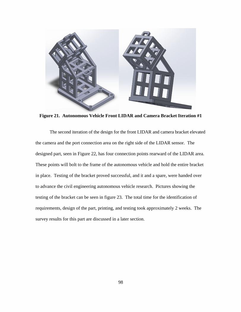
98
Figure 21. Autonomous Vehicle Front LIDAR and Camera Bracket Iteration #1
The second iteration of the design for the front LIDAR and camera bracket elevated
the camera and the port connection area on the right side of the LIDAR sensor. The
designed part, seen in Figure 22, has four connection points rearward of the LIDAR area.
These points will bolt to the frame of the autonomous vehicle and hold the entire bracket
in place. Testing of the bracket proved successful, and it and a spare, were handed over
to advance the civil engineering autonomous vehicle research. Pictures showing the
testing of the bracket can be seen in figure 23. The total time for the identification of
requirements, design of the part, printing, and testing took approximately 2 weeks. The
survey results for this part are discussed in a later section.

99
Figure 22. Autonomous Vehicle Front LIDAR and Camera Bracket Iteration #2
Figure 23. Front LIDAR and Camera Bracket Testing
Rear LIDAR Bracket Design
The autonomous vehicle required a separate LIDAR sensor, the Pulsed Light,
Inc® LIDAR Lite™ unidirectional laser range finder, on the rear of the vehicle for the
purpose of determining specific distance and location measurement. The sensor, seen in
Figure 24, shows four separate connection points; however they are perpendicular to the
base to the vehicle. Again, prior to an additive manufacturing solution, this LIDAR
sensor was cable tied to the base near the rear of the vehicle. Due to the sensor’s having

100
zero requirements for placement on the vehicle, the original location unnecessarily took up
valuable space on the base plate. The design of the LIDAR bracket aimed to free space
for on the robot by strategically removing the sensor from the footprint of the base plate
and hanging it from the rear of the vehicle.
Figure 24. LiDAR Lite™ Range Finder (RobotShop, n.d.)
This component required a single design iteration (Figure 25) and included four
connection points for attaching the bracket to the vehicle and four connection points for
attaching the sensor to the bracket. The testing of the rear LIDAR bracket proved
extremely successful and provided more reliable results from the LIDAR sensor than in
previous tests. Since this design allowed the connection of the sensor to the vehicle
without taking up critical space, the researcher was able to improve the location of certain
other pieces of equipment on the vehicle. The design process for the rear LIDAR camera
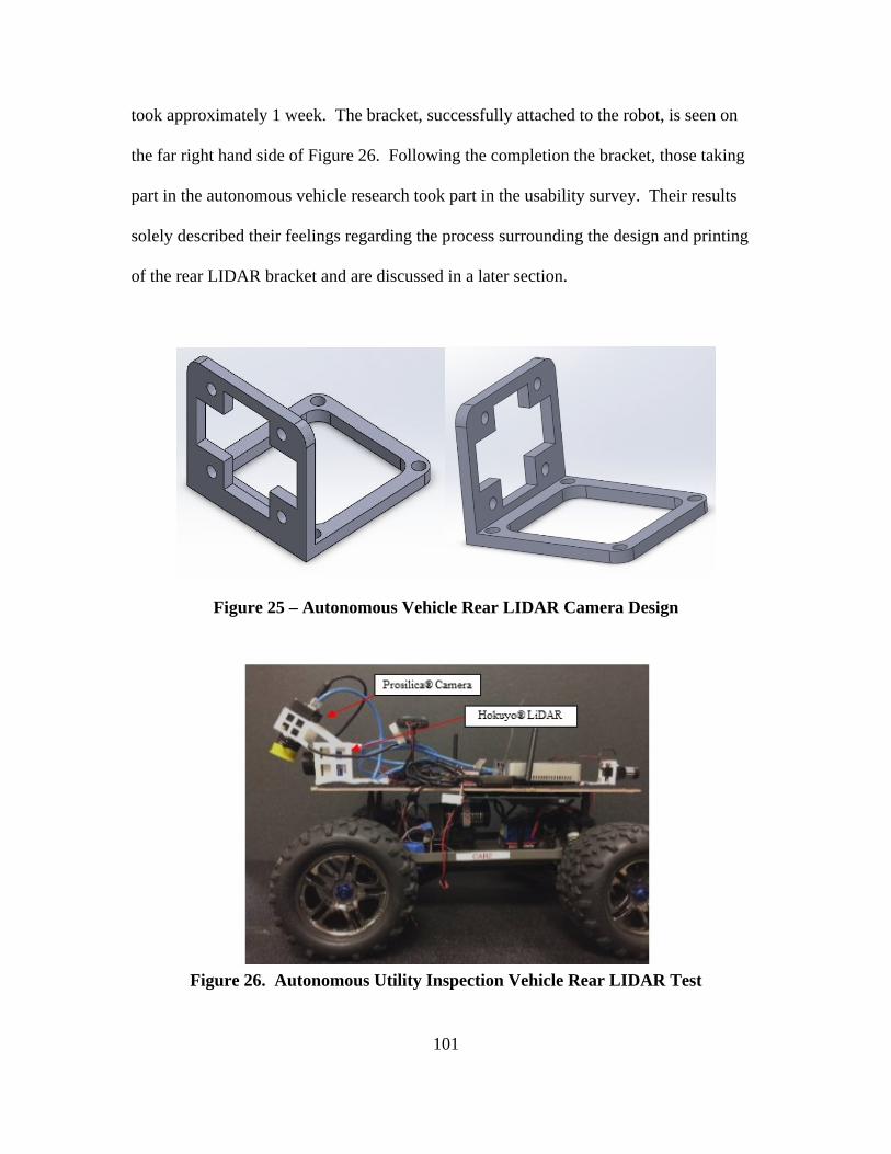
101
took approximately 1 week. The bracket, successfully attached to the robot, is seen on
the far right hand side of Figure 26. Following the completion the bracket, those taking
part in the autonomous vehicle research took part in the usability survey. Their results
solely described their feelings regarding the process surrounding the design and printing
of the rear LIDAR bracket and are discussed in a later section.
Figure 25 – Autonomous Vehicle Rear LIDAR Camera Design
Figure 26. Autonomous Utility Inspection Vehicle Rear LIDAR Test
102
Large and Small Battery Receptacle Design
The autonomous vehicle and all the equipment it carries is powered by numerous
batteries of different shapes and sizes. The two batteries powering all the equipment and
causing limitations for the vehicle have dimensions of 7 in × 3 in × 1.5 in and the other 5
in × 2.5 in × 1.25 in. Prior to an additively manufactured solution, no practical method of
securing the batteries to the vehicle was available. During test runs with the vehicle, the
batteries were simply placed on top without any constraints; however, the batteries
tended to fall off when the vehicle was subjected to rough terrain. The design of the
battery imposed minimal requirements about the placement, except that they be spread
out as widely as possible to distribute their weight. This was taken into account during
the initial design process.
Two long connection pieces beneath the base plate of the autonomous vehicle snap
into place to hold other vehicle pieces in place. The design from that connection piece
was adapted to place two additional battery receptacles on top, the larger one on the left
side of the vehicle and the smaller one on the right. The design, seen in Figure 27,
created a box wherein the batteries are securely held and easily connect to the vehicle. The
orientation of the two designs was due to how each side of vehicle connected to the long
piece of the bracket.

103
Figure 27. Autonomous Vehicle Large Battery Receptacle Design (left), Small
Battery Design (right)
Additional design iterations did not change the design, only strengthened the
walls for more support. Testing of the printed pieces resulted in successful prints and the
two brackets were handed to the student for her research. The design and printing of
each bracket, including the different iterations, took approximately 2 weeks. Following
the design process, those close to the research took part in the usability survey for the two
brackets. While the two brackets were discussed concurrently due to their similar
requirements, each had its own design process; therefore, two separate surveys were
conducted to provide the most accurate results. The attached brackets are seen in Figure
28 and Figure 29.

104
Figure 28. Autonomous Vehicle Battery Receptacle during Testing
Figure 29. Autonomous Vehicle Battery Receptacle Attached to Robot
Utility Pipe Inspection Autonomous Vehicle Bracket Survey Results
Those working on the autonomous vehicle research took part in the usability survey
regarding the design and printing of the four brackets designed specifically for the
autonomous vehicle. Both researchers have at least 14 years’ of experience within the
engineering career field. They both understood that each survey is completely based on the
design and printing of only the specific bracket in question for the autonomous vehicle, and
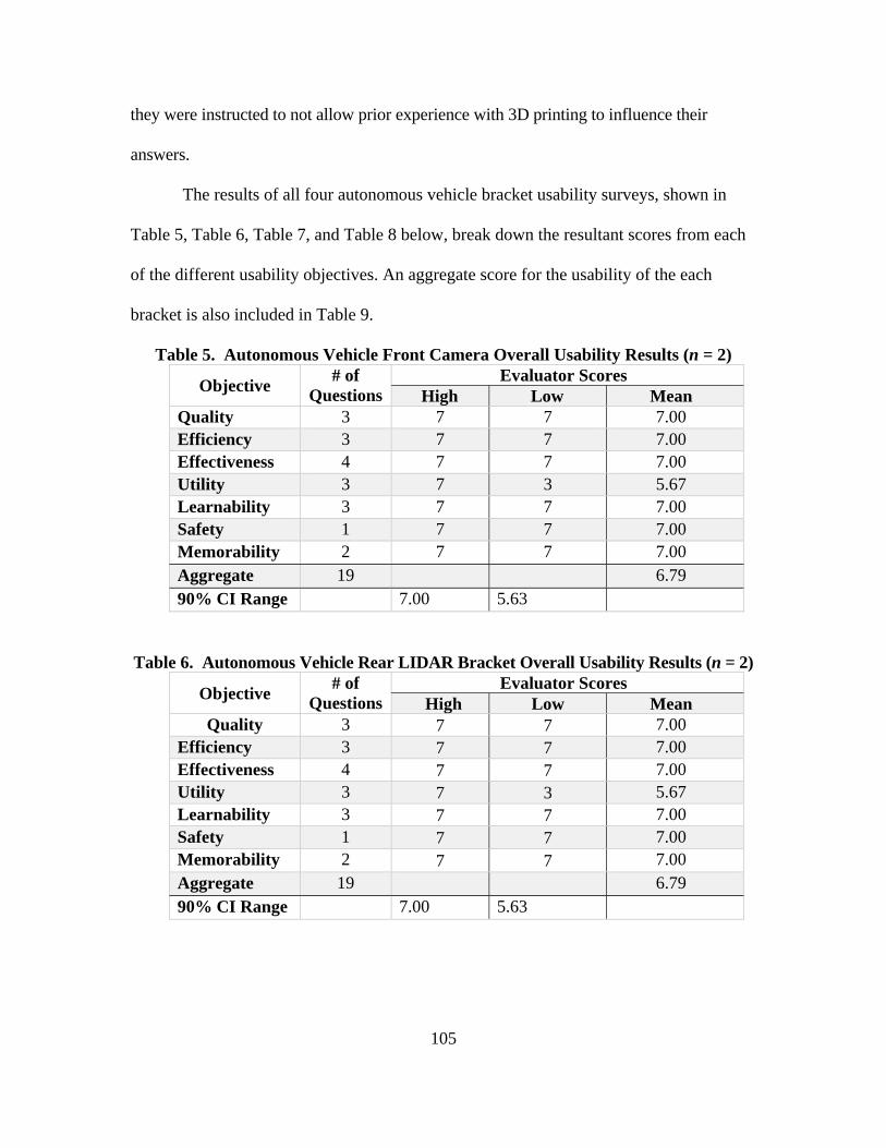
105
they were instructed to not allow prior experience with 3D printing to influence their
answers.
The results of all four autonomous vehicle bracket usability surveys, shown in
Table 5, Table 6, Table 7, and Table 8 below, break down the resultant scores from each
of the different usability objectives. An aggregate score for the usability of the each
bracket is also included in Table 9.
Table 5. Autonomous Vehicle Front Camera Overall Usability Results (n = 2)
Objective # of
QuestionsEvaluator Scores
High Low Mean Quality 3 7 7 7.00 Efficiency 3 7 7 7.00 Effectiveness 4 7 7 7.00 Utility 3 7 3 5.67 Learnability 3 7 7 7.00 Safety 1 7 7 7.00 Memorability 2 7 7 7.00 Aggregate 19 6.79 90% CI Range 7.00 5.63
Table 6. Autonomous Vehicle Rear LIDAR Bracket Overall Usability Results (n = 2)
Objective # of
QuestionsEvaluator Scores
High Low Mean Quality 3 7 7 7.00
Efficiency 3 7 7 7.00 Effectiveness 4 7 7 7.00 Utility 3 7 3 5.67 Learnability 3 7 7 7.00 Safety 1 7 7 7.00 Memorability 2 7 7 7.00 Aggregate 19 6.79 90% CI Range 7.00 5.63
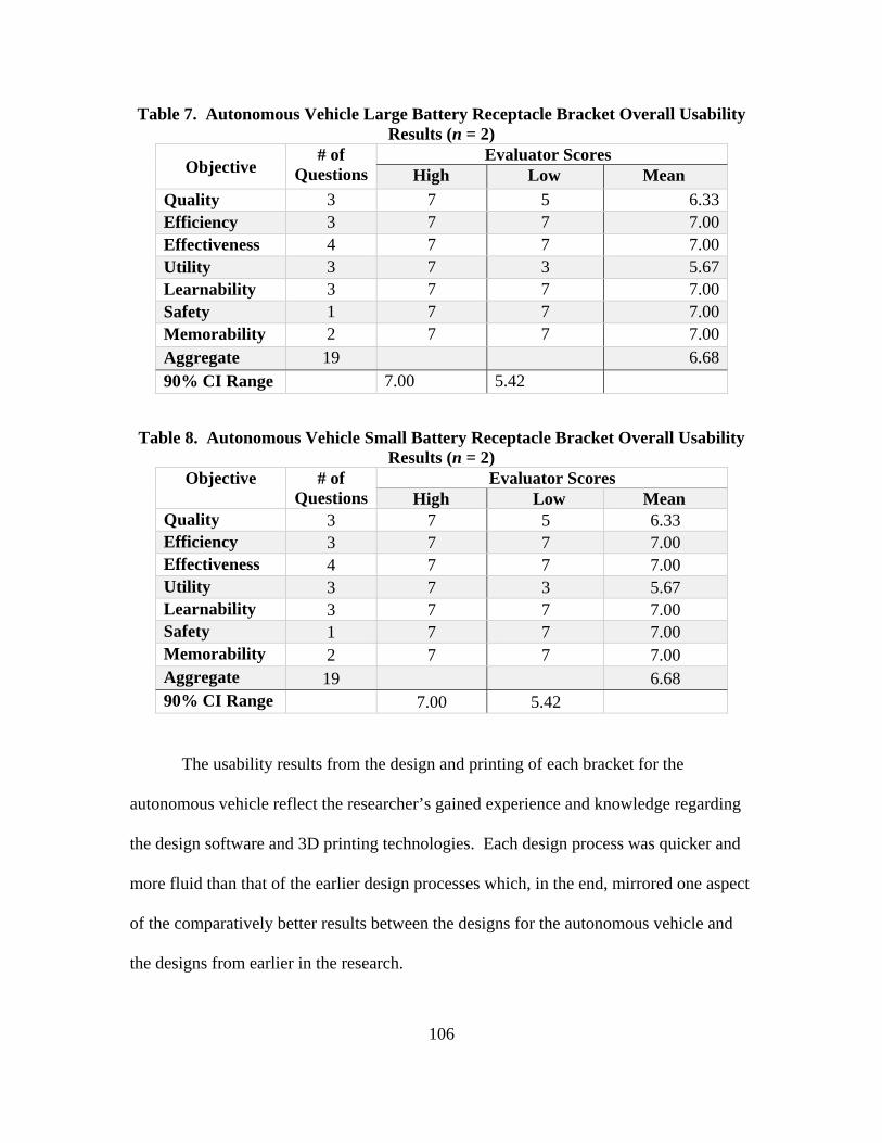
106
Table 7. Autonomous Vehicle Large Battery Receptacle Bracket Overall Usability Results (n = 2)
Objective # of
QuestionsEvaluator Scores
High Low Mean
Quality 3 7 5 6.33Efficiency 3 7 7 7.00Effectiveness 4 7 7 7.00Utility 3 7 3 5.67Learnability 3 7 7 7.00Safety 1 7 7 7.00Memorability 2 7 7 7.00Aggregate 19 6.6890% CI Range 7.00 5.42
Table 8. Autonomous Vehicle Small Battery Receptacle Bracket Overall Usability Results (n = 2)
Objective # of Questions
Evaluator Scores High Low Mean
Quality 3 7 5 6.33 Efficiency 3 7 7 7.00 Effectiveness 4 7 7 7.00 Utility 3 7 3 5.67 Learnability 3 7 7 7.00 Safety 1 7 7 7.00 Memorability 2 7 7 7.00 Aggregate 19 6.68 90% CI Range 7.00 5.42
The usability results from the design and printing of each bracket for the
autonomous vehicle reflect the researcher’s gained experience and knowledge regarding
the design software and 3D printing technologies. Each design process was quicker and
more fluid than that of the earlier design processes which, in the end, mirrored one aspect
of the comparatively better results between the designs for the autonomous vehicle and
the designs from earlier in the research.

107
Six separate usability objectives received a perfect score for every bracket except
the battery receptacles. With each bracket, “utility” was the common component not
receiving a perfect score. Just as in the previous designs, the brackets for the autonomous
vehicle were designed for only one use and the utility component mirrored that finding.
That being said, the results from the EOD bracket and the computer engineering jig
showed that due to similar questions, if usability were low, then the same should be seen
in the results for learnability. Since learnability was a perfect score for all four brackets,
the users of the part were questioned regarding this finding. Both users regarded the
“discovering different uses for the tool” question as being tied more to the other possible
uses for 3D printing, rather than the actual printed tool. This corroborates their answers
on the survey, but reaffirms the possible need for additional questions within the survey
or at least substantial clarification of certain questions.
For the two printed battery receptacles, each one was marked down in the quality
component for not being durable. This finding was expected due to the multiple breaks
that occurred during the testing of the part. The final design weighed additional material
with additional durability and found that the robot could not hold much more weight;
therefore, risk was accepted regarding the durability of the brackets to limit the weight of
the part.
While the scores all came out above 4, which is considered usable, the main test
for usability is that all four brackets are currently being used on the UGV to study
autonomous vehicle utility pipe inspections. This result undeniably proves the
overwhelming usability of these printed parts for the need they were intended to fulfill.
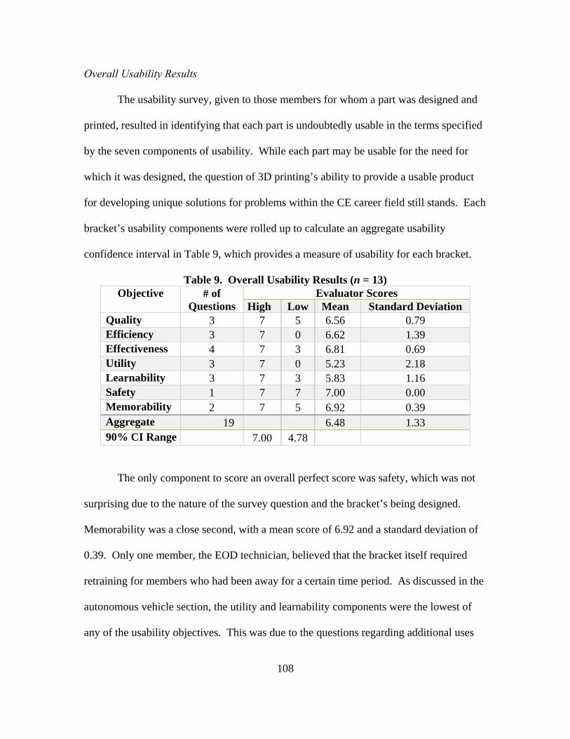
108
Overall Usability Results
The usability survey, given to those members for whom a part was designed and
printed, resulted in identifying that each part is undoubtedly usable in the terms specified
by the seven components of usability. While each part may be usable for the need for
which it was designed, the question of 3D printing’s ability to provide a usable product
for developing unique solutions for problems within the CE career field still stands. Each
bracket’s usability components were rolled up to calculate an aggregate usability
confidence interval in Table 9, which provides a measure of usability for each bracket.
Table 9. Overall Usability Results (n = 13) Objective # of
Questions Evaluator Scores
High Low Mean Standard Deviation Quality 3 7 5 6.56 0.79 Efficiency 3 7 0 6.62 1.39 Effectiveness 4 7 3 6.81 0.69 Utility 3 7 0 5.23 2.18 Learnability 3 7 3 5.83 1.16 Safety 1 7 7 7.00 0.00 Memorability 2 7 5 6.92 0.39 Aggregate 19 6.48 1.33 90% CI Range 7.00 4.78
The only component to score an overall perfect score was safety, which was not
surprising due to the nature of the survey question and the bracket’s being designed.
Memorability was a close second, with a mean score of 6.92 and a standard deviation of
0.39. Only one member, the EOD technician, believed that the bracket itself required
retraining for members who had been away for a certain time period. As discussed in the
autonomous vehicle section, the utility and learnability components were the lowest of
any of the usability objectives. This was due to the questions regarding additional uses

109
for the tool. Since each tool was designed for a specific purpose, these objectives had the
largest variance in responses. In the end, the mean overall response was 6.48, with a
standard deviation of only 1.33. Based on the survey from all 13 users of the designed
and printed brackets, the 90% CI suggests that any bracket designed and printed using
additive manufacturing technology would most likely fall somewhere between a 4.78 and
7.0 on the usability scale. This score interval, along with the fact that every printed part
is currently being used within the intended operation, provides evidence of the usability
of additive manufacturing technology as a capable tool for solving problems within CE.
Summary
This chapter presented the results of the identification, design, and printing of
potential 3D printing applications, as well as the usability surveys that were conducted
for this research. In phase I of the research, specific tools and jigs were identified,
designed, and printed using additive manufacturing technology. Following phase I, phase
II consisted of conducting usability surveys to determine the overall value and ability of
3D printing for solving unique problems within CE. The conclusions and interpretations
taken from the survey were presented to the committee for their final thoughts and
opinions. The final results of this research indicate the interpretations and opinions solely
of the researcher, with advisory input from the committee members, regarding various
topics dealing with additive and traditional manufacturing. In Chapter V of this
document, the answers to the investigative questions posed in this thesis will be derived
from the results and analysis conducted by the researcher. All discussions, including
additional follow-on research, will relate to the overall thesis research objective.

110
V. Conclusions and Recommendations
The objective of this chapter is to develop conclusions from this research and to
propose recommendations for future work exploring AM applications for tools and jigs
within USAF CE operations. This chapter will first evaluate the investigative questions
that guided the research and ascertain answers to these questions based upon the results
presented in Chapter IV. The determining answers to the research questions will then be
rolled up to investigate and answer the overall research objective of this thesis. Finally,
this chapter will confer recommendations for possible actions in response to the results of
this research and discuss future areas of research with regards to the topic of AM within
USAF CE operations.
Investigative Questions Answered
To meet the overall objective of this research, four investigative questions were
analyzed. The results of the overall design process and of the usability survey were
analyzed within the context of these specific questions to reach a final conclusion
regarding the overall thesis research objective. Both the research questions and the
subsequent analysis are discussed below.
1. What added value does 3D printing bring to USAF civil engineering?
This question was meant to explore the benefits and advantages of 3D printing
through a detailed exploration of current applications, within both the civilian and
military sector, by members who are utilizing additive manufacturing technology in have
operational contexts similar to a USAF Civil Engineering Unit’s. Within the detailed
literature review, it is apparent that additive manufacturing is a technology with unknown
111
limitations. Companies are using the equipment in a variety of ways and developing new
uses and methods on a daily basis. All of the branches within the DoD are researching
applications of 3D printing within their respective operations; however, the Air Force is
behind in allowing their technicians to find the best applications for the technology. The
Army’s Ex-Labs and the Navy’s “Print the Fleet” concepts are the epitome of the
expression “need drives innovation.” Each of these branches realizes that introducing
additive manufacturing to their technical experts within an operational environment will
cause the most beneficial applications for the technology to emerge. Searching out needs
and applications for a technology becomes much more difficult when attempted in the
confines of an office or laboratory.
Additive manufacturing is already benefiting certain Army and Navy units
through the identification of specific parts by troops in the trenches. The few parts that
were designed and printed within this research prove there is a potential need and value
within civil engineering for additive manufacturing. As time moves on, an exhaustive
database of designs could be the answer to maintaining our outdated infrastructure. The
“print to fit,” as well as the “just in time” manufacturing could reduce the size of the CE
footprint by doing away with inventories and material control buildings. The value added
to CE through the use of additive manufacturing has been identified through the design,
printing, and implementation of a limited number of parts and tools; however, the real
potential value could be identified through the use of strategically placed printers for
operational use.
2. What attributes make a tool or jig a good candidate to be manufactured using
additive manufacturing?
112
This question looked to explore the characteristics of a tool or jig that was more
efficiently manufactured using 3D printing than traditional manufacturing methods.
Chapter II pointed out the laborious method that accompanied any product through a
traditional manufacturing design process. This process will never go away for those
items that allow for high-volume production with minimum customization, because the
unit cost is unbeatable. Additive manufacturing is a benefit for those products requiring
customization and quick turnaround, and of which a small number is to be produced.
Phase I of the research identified six possible applications where additive
manufacturing provided some sort of solution to a recognized problem. Each of the
needs could have been solved using traditional manufacturing methods. The
requirements would have been identified, the constraints determined, and the design
developed; however, this would have taken a greater amount of time and cost a lot more
money due to the need for only one part, and the design would not have been refined due
to geometric constraints and lack of design iterations. Traditional manufacturing
methods would not have provided the best product for the end user.
On the contrary, additive manufacturing provided quick designs and prints. Even
if AFIT had no printer for this research, 3D printing companies are emerging more and
more to which a person can take a design and have it printed out. The costs were low and
the iterative design process allowed for repeated testing of prototypes until the final
product was exactly the way the end user desired. The design changes were simple and
easy, and most parts were completed in a few weeks or less.
The attributes for benefiting from additive manufacturing extend well beyond the
actual product. If the product is already created, then can additive manufacturing improve

113
the amount of material or design? Is the need for the part dire or can it wait? Speed,
customizability, and the number of parts needed are all attributes that drive whether or
not additive manufacturing provides the most benefits for the creation of the product.
To civil engineering, deployed environments and outdated equipment are
common hurdles dealt with at base level. The ability of a 3D printer to print any design
in a matter of hours could bring a new critical tool to the battlefront and make the
engineer a more flexible and resilient warfighter.
3. Can questionnaires about a select few printed tools and jigs be used to illustrate
the value of 3D printing over traditional manufacturing?
This question sought to establish that it is possible to show that a select few tools
could be printed and the users surveyed, through the use of a questionnaire, to illustrate
the value of additive manufacturing. The usability survey, conducted in phase II of the
research, provided consistent results illustrating the benefits of additive manufacturing
vice traditional manufacturing. As discussed in the answer to investigative question 2,
certain attributes for a product make it more beneficial to be printed using a 3D printer.
This point was further strengthened through the use of the usability survey.
4. How is usability for designing and printing jigs defined and measured?
By surveying users of the 3D printed parts and tools, this investigative question
was intended to explore the benefit of having a 3D printer for the purpose of designing
and printing custom jigs within the unit. Defining the term usability and determining a
method for measuring it offers a validation test for 3D printing within CE units. Within
phase II of the research, the concept of usability was integrated into a survey to determine
the value of 3D printing for CE operations. Usability is a term commonly used within

114
software design to determine of the ease with which a user can operate a certain program
or if the user can comprehend a certain platform interface. Through six objectives or
components, the usability of the product is determined and then either sent back for
changes or sent on for testing.
Usability, as defined within this research, is the facility with which the user is able
to utilize the designed tool for the original need identified. By rating seven different
properties (quality, efficiency, effectiveness, utility, safety, learnability, and
memorability), a survey was conducted to determine the benefit brought to specific units
for whom this research identified a problem and designed a part to solve it. If the overall
consensus is that the 3D printed part provided a useable item for the units, then it will be
determined that the questionnaire, coupled with the design, printing, and testing of the
part, confirms the value and applicability of additive manufacturing within CE units.
Conclusions of Research
The four investigative questions were intended to provide context and shed light
on meeting the overall objective of the research. The overarching objective of the
research outlined in Chapter I was to determine whether 3D printing added significant
value to the CE career field and if the current technology had reached a point capable of
fulfilling the requirements within the career field. Based on the objective and results of
the research, the following conclusions were deduced from the printing design process
and ensuing usability survey results:
1. Additive manufacturing is a technology that will begin affecting a majority of
the processes used on a daily basis. As the technology grows, the capability,

115
reliability, and technical ability of the printers will provide more efficient
options for modernizing the operations within CE.
2. AM technology has reached a point at which the only way to determine and
validate specific career applications is to introduce the technology into an
operational environment and allow the technicians to identify areas for
printing potential. Based on the successes within the Navy and Army with
regards to the implementation of AM into operational units, it can be assumed
that similar successes will be found over time if the Air Force chooses to
strategically integrate AM into their operational portfolio.
3. Successfully introducing AM into an operational CE unit is predicated on
teaching all members about the capability of the technology. Additive
manufacturing is a new technology that is relatively unknown to many within
the engineering career field. To fully identify the possibilities of AM within a
unit, the members of the unit must be educated on how the technology works
and its potential capability. Additionally, the members must be shown
specific examples related to their field of work where AM improved a
process, created a unique part, or created a solution based on a past need. No
educational tool is more effective than allowing users to see something with
which they can relate and visualize. The more members understand the
potential of additive manufacturing, the more possible applications will
surface.
4. Additive manufacturing offers potentially significant value for the CE career
field based on the need for “just in time” manufacturing and rapid prototyping

116
capabilities. Further studies should explore facility maintenance, contingency
basing, and other civil engineer applications.
These statements, deductively constructed from the in depth literature review,
specific part design process, and usability survey results, satisfy the research objective of
this thesis.
Significance of Research
This research is one of the first studies looking to identify potential applications
for additive manufacturing of tools and jigs for civil engineering. As AM is a new
technology and its growth seen on an annual basis is significant, this research provides a
foundation and baseline for additional follow on research. While being a study for Air
Force applications, the resulting conclusions are not specific to Air Force operations and
can be used in the decision making of other branches. Similarly, the conclusions of this
research can guide leadership and decision makers to understand the need to invest in
additive manufacturing and other technologies of the future. It is imperative to continue
funding research into possible applications for AM within home station and deployed
operations. Only through further exploration and proof will the conclusions provide
enough of a basis for a test case for operational civil engineering AM applications.
Within the literature review conducted in Chapter II of this thesis, the current
processes of traditional manufacturing were identified and compared to the rapid process
of additive manufacturing. An additional in-depth review of current military applications
of AM technology illustrates the current state of the technology and its benefits.
117
Companies and militaries around the world are leveraging the potential benefits of AM as
a method for making a leaner, more flexible, and more capable fighting force.
The overall significance of this research proves that “need drives innovation.”
There is a need for better-designed parts and improved processes within the operations of
CE and the Air Force. Decision makers should understand that the true potential for
additive manufacturing will not be determined within a laboratory. The true applications
for deployed and home station operations will be identified once the Airman on the
ground becomes familiar with the technology and understands the process and benefits it
is capable of providing.
Finally, this research is significant in showing leadership that the Air Force is
behind the curve because the Army and Navy are already utilizing AM within operational
environments. Multiple uses through the Army’s Ex-labs and the Navy’s “Print the
Fleet” concept are delivering quantifiable savings of time and money for missions in the
theater of operations. This study provides a basic process for the development and design
of parts within any environment and is a significant step in determining the potential
possibilities for AM within the CE career field.
Limitations of Research
While there is an unequivocal potential need for AM within the CE career field,
several limitations caused the research scope to not encompass all types of tools and
parts. The printing capabilities at AFIT allowed for minimal material variation within the
parts and did not accommodate parts requiring multiple materials. The polymer material
used in the printed tools and parts was brittle, requiring sturdy rather than mose-efficient

118
designs. Having access to multiple printing materials would have garnered a wider range
of tool applications and optimal designs. Industry empolys printers capable of fulfilling
these needs; however, they were not researched in depth and were not available for this
research.
The other limitation is the governing body regulating the use of parts and
equipment within the CE career field. Due to the nature of the work conducted by the
technicians within CE, it is recognized that certain parts are considered off limits for
design and printing based on regulations and codes set forth for safety concerns. This is
not to say that in a deployed environment or emergency situation, AM could not be used
to thwart a problem otherwise restricted based on those codes and regulations.
Recommendations for Action
As a part of the conclusions within this research, several actionable items have
been identified. Each identified item merits possible future research and validation.
Each of the four branches of the DoD is conducting its own research into potential
applications for AM; however, very little joint research has been conducted to leverage
each branch’s knowledge for the betterment of the entire DoD. As a result, the Air Force
has to duplicate efforts of the Army and Navy rather than utilizing the strength of their
personnel to identify potential applications. Finally, a global network must be created for
sharing and distribution of files for 3D printed parts, tools, and brackets. Each of these
topics is discussed further in this section.

119
Duplication of Ex-labs/Print the Fleet
The Army and the Navy are both ahead of the Air Force in integrating AM
technology into operational environments. As discussed before, both believed that if they
put the technology out for the use of their technical experts, then the applications would
identify themselves—and they were correct. Both branches report multiple successes in
terms of cost, time, and logistical savings found through the use of printing specific parts.
Training on CAD software or the capabilities of the 3D printer was not an up-front
requirement—all they technician was asked to do is understand what the technology
could provide in a deployed situation and then look for possible applications. If a
problem could not be solved by the engineer working with CAD and the 3D printer, then
CONUS reachback capability and traditional procurement methods were still available.
Still, solutions were derived from 3D printing for problems brought to Ex-lab engineers
at their deployed location. Similarly, the Navy is experiencing the same success after
making an effort to educate each sailor on 3D printing technology, especially those on a
ship carrying the technology. The Air Force does not have to reinvent the wheel when it
comes to integrating the printers into an operational unit.
Currently, AM does not have a printer that completely fits all the needs within the
Air Force. Each possible application within the Air Force requires the printer to use
various materials, as well as specific print tolerances and sizes. Until a printer is able to
switch among a large number of materials, the Air Force must realize that researching the
technology will require procuring a variety of printers covering the majority of materials
and print sizes. Similar to the Army’s Ex-lab, the Air Force must make different types of
printers available for engineers to use for unique designs and problem solving

120
application. The pilot study would include thoroughly educating one or two engineers on
the CAD and printing equipment, followed by transporting the engineers and the
equipment together in a transportable 3D printing package to a large CONUS or deployed
environment. At those locations, the engineer’s job will be to educate Airmen about the
benefits of the 3D printer and help identify and solve problems through the use of AM
printing technology. This could start with two packages and then over time expand to the
point of having one package covering every region. As time progresses, members will
become more knowledgeable about the technology and the number of applications will
grow. This is the optimum solution without having to commit a significant upfront
investment into the integration of additive manufacturing in operational CE units.
Global 3D Design Sharepoint
To receive the largest benefit from the advantages of AM, its full potential must
be realized and acted upon. The different between traditional manufacturing and additive
manufacturing is that additive manufacturing does not need a mold or cast to create the
part. A design finished by someone at Wright–Patterson AFB could be e-mailed and
printed in Afghanistan within hours. This is why a global 3D design library site could
and should be set up for engineers from around the globe to submit their designs for
parts, tools, and brackets. A majority of printers accept Google Sketchup® as sufficient
design software, so an Air Force-wide license is not required for members to work on
individual designs. Each design would be deposited into specific system folders and then
identified within the comments as to the make, model, and manufacturer that the part is
compatible with. Over time, as the engineers gain experience with the CAD software, the
entire CE inventory could be designed and available through this site. Certain Building

121
Information Modeling (BIM) software could cross reference the available designs and
quickly pull them up for building requirements. This would completely negate a majority
of transportation costs and risks to sending specific parts to deployed environments.
Possibilities for Future Research
Additive manufacturing is a growing technology that is still finding its place in
the world. It is imperative that the Air Force and the DoD maintain their investment in
additive manufacturing research to get on the leading edge of the new technology.
Possibilities for future research into additive manufacturing include the following:
Air Force applications and validity of need for the production of large structures
through the use of additive manufacturing.
Comparison of strength characteristics for traditionally manufactured products
versus additively manufactured products.
Continuing to determine specific applications of additive manufacturing for Air
Force civil engineering tools and jigs.
Development and study of integration protocols for additive manufacturing into
Air Force civil engineering operational units.
A partnership with the Air Force Research Laboratory and America Makes, Inc.
to determine methods to increase print speed while maintaining print reliability.
Specific applicability of metal, composite, and multi-material printers within Air
Force civil engineering.
122
Conclusion
This research has determined that 1) additive manufacturing is a technology
capable of affecting future civil engineering daily operations. 2) AM has reached a point
that the next step in validating its potential is to integrate the technology into a select few
Air Force CE operational units. 3) Successfully integrating the technology into a CE unit
is dependent upon the education of its Airman about the benefits and capabilities of the
technology. 4) 3D scanning is a technology that could rapidly speed up the creation of
accurate designs; however, the technology is approximately 5 years away from being
reliable for the use of creating a global CE database of 3D designs. 5) AM leverages
CE’s need for “just in time” manufacturing and rapid prototyping capabilities within the
facility maintenance operations. This approach to determining the value of 3D printing
for CE operations is untested for this type of research; however, its use in software
development, as well as the committee’s overall approval, validates the approach taken to
reach the overall research conclusion. With declining budgets and increasing demands
on the operations of USAF civil engineers, AM provides a unique tool capable of
providing solutions to the maintenance of outdated equipment and customizable products.
The need has been identified and validated; therefore, there is no better time than now to
invest in and integrate the manufacturing technology of the future into the arsenal of the
civil engineering warfighter.

123
Appendix A – Internal Review Board Survey Exemption Package
Figure A - 1. IRB Exemption Letter (Dated: Nov 18th, 2015)

124
Figure A - 2. IRB Memorandum for Exemption

125
Figure A - 3. IRB Memorandum for Exemption (Cont.)

126
Verbal Statement for Particpants
Hello, I am Capt Brad Shields. I am a Masters Student at the Air Force Institute of
Technology. I am conducting research in collaboration with my advisor, Maj Vhance
Valencia that is being sponsored by the Air Force Civil Engineer Center (AFCEC). You
are being asked to participate in a short survey on the applicability of 3D printing
technology within an operational squadron. Participation in the survey is voluntary,
anonymous, and there is no penalty for non-participation. If you choose to participate in
the survey, no PII will be collected. I will hand out the survey forms and you can choose
to participate after looking over the survey content. There are several assumptions that
need to be mentioned prior to starting the survey. This survey is focused on validating
the potential use of 3D printing technology to solve current operational problems within a
squadron. Those participating in the survey need to have a working understanding of the
original problem, as well as the problem solution using the 3D printed part. Please
indicate whether the printed part actually solved the problem or made it more difficult to
accomplish the mission. Please let me know if you have any questions at this time.
Thank you for your time.
Figure A - 4. IRB Verbal Statement for Participants
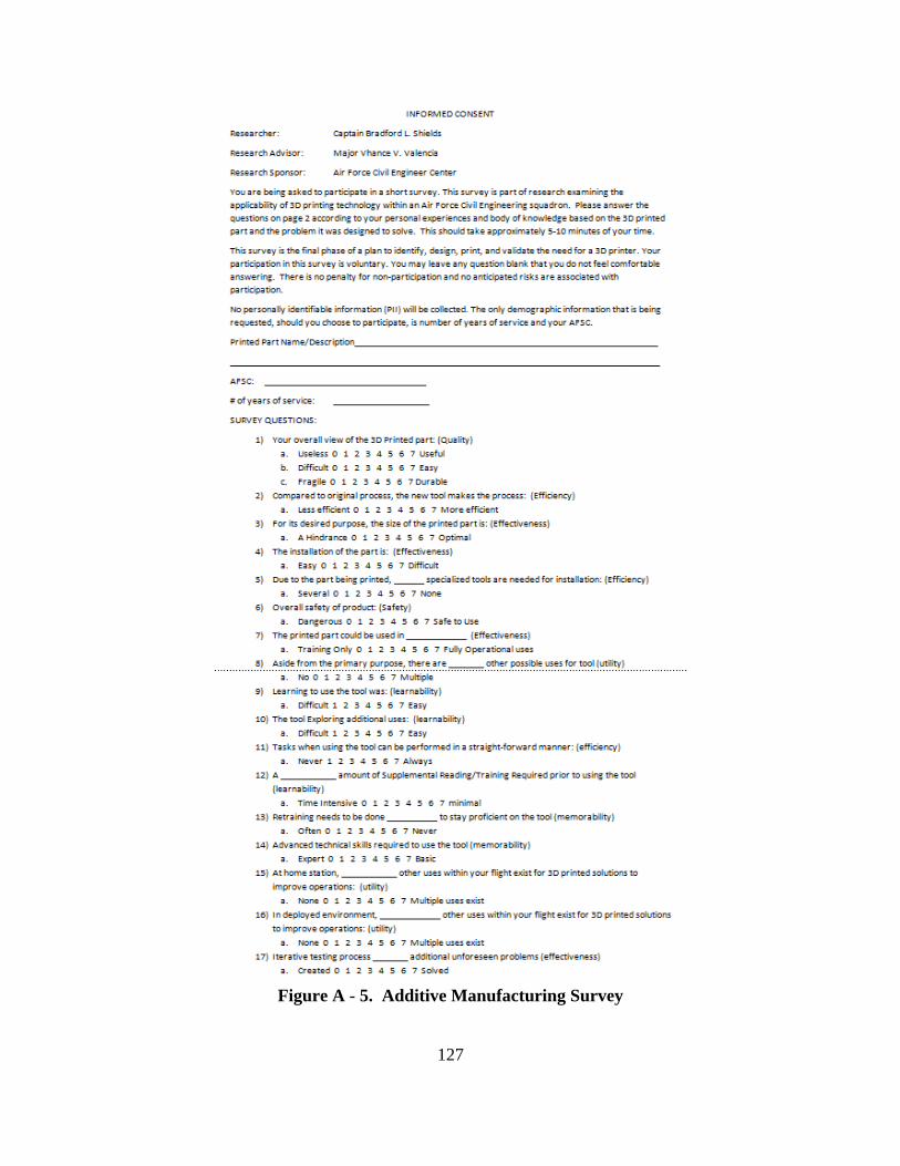
127
Figure A - 5. Additive Manufacturing Survey
128
References
MakerBot® Industries LLC. (2015). Retrieved from www.makerbot.com
3D Systems Supports USMC War Game involving 3D Printing and Scanning. (2015, August 27). Retrieved from Naval-Technology Online: http://www.naval-technology.com/news/news3d-systems-supports-usmcs-wargame-involving-3d-printing-and-scanning-4354841
AFRL. (2011). Air Force Science & Technology Plan . Wright-Patterson AFB, OH: Air Force Research Laboratory.
Asclipiadis, M. A. (2014, July 9). Rapid Equipping Force uses 3-D Printing on the Frontline. Retrieved from Army.mil: http://www.army.mil/article/129635
ASTM International. (2015, May 20). Standard Terminology for Additive Manufacturing Technologies (F2792-12a). West Conshohocken, PA.
Audretsch, D. B. (2009). The Entrepreneurial Society. The Journal of Technology Transfer, 245-254.
AVT. ((n.d.)). Prosilica Cameras. Retrieved from https://www.alliedvision.com/en/digital-industrial-camera-solutions.html
Birtchnell, T., & Caletrio, J. (2014). Elite Mobilities. New York, NY: Routledge.
Birtchnell, T., Urry, J., Cook, C., & Curry, A. (2012). Freight Miles: The Impacts of 3D Printing on Transport and Society. London, UK: Economic & Social Research Council.
Blanchard, B., & Fabrycky, W. (2011). Systems Engineering and Analysis. Englewood Cliffs, N.J.: Prentice-Hall.
Bonvillian, W. (2004). Meeting the new challenge to U.S. economic competitiveness. Issues in Science and Technology, Vol 21.1, 75-82.
Bourell, D., Campbell, I., & Gibson, I. (2012). Additive Manufacturing: Rapid Prototyping Comes of Age. Rapid Prototyping Journal, 255-258.
Brown, R., Davis, J., Dobson, M., & Mallicoat, D. (2014, May-June). 3D Printing, How Much Will It Improve the DoD Supply Chain of the Future? Defense Acquisition, Technology and Logistics, 6-10.

129
Campbell, T. A., & Ivanova, O. S. (2013). Additive Manufacturing as a Disruptive Technology: Implications of Three-Dimensional Printing. Technology and Innovation, 15, 67-79.
Cooper, J. (2011, August 5). Langley EOD: Serving at home, overseas. Peninsula Warrior.
de Weck, O. L., Roos, D., & Magee, C. L. (2011). Engineering Systems: Meeting Human Needs in a Complex Technological World. Cambridge, MA: Massachusetts Institute of Technology.
DSMC. (1990). Systems Engineering Management Guide. Washington, DC: Defense Systems Management College, Superintendent of Documents.
Economies of Scope. (2015, Jul 17). Retrieved from Investing Answers : http://www.investinganswers.com/financial-dictionary/economics/economies-scope-1009
FDOT. (2008). The Effect of Rising Fuel Costs on Goods Movement Mode Choice and Infrastructure Needs. Tampa Bay, FL: Florida Department of Transportation.
FLIR. (2015). identiFINDER Radiation Detection. Retrieved February 26, 2015, from FLIR.com: http://www.flir.com/threatdetection/display/?id=63333
Fluke Biomedical. (2015). 451P Pressurized μR Ion Chamber Radiation Survey Meter. Retrieved February 23, 2015, from Fluke Biomedical: http://www.flukebiomedical.com/biomedical/usen/radiation-safety/survey-meters/451p-pressurized-ion-chamber-radiation-detector-survey-meter.htm?PID=54793
Garrett, B. (2014). 3D Printing: New Economic Paradigms and Strategic Shifts. Global Policy, 5(1), 70-75.
Gross, B. C., Erkal, J. L., Lockwood, S. Y., Chen, C., & Spence, D. M. (2014). Evaluation of 3D Printing and Its Potential Impact on Biotechnology and the Chemical Sciences. Analytical Chemistry, Vol. 86, 3240-3253.
Halterman, T. (2014, August 28). 3D Systems Shows Marines the Way Forward at Expeditionary Logistics Test. Retrieved from 3D Printer World: http://www.3dprinterworld.com/article/3d-systems-shows-marines-way-forward-expeditionary-logistics-test

130
Hart, B. (2012, March 06). Will 3D Printing Change the World? Retrieved November 15th, 2014, from Forbes Online: http://www.forbes.com/sites/gcaptain/2012/03/06/will-3d-printing-change-the-world/
Kostoff, R. N., Boylan, R., & Simone, G. R. (2004). Disruptive Technology Roadmaps. Technological Forecasting & Social Change, 71, 141-159.
Kuhn, H. H., & Collier, K. (2014, May 12). Additive Manufacturing Processes and Materials. Youngstown, OH, US: America Makes.
Lipson, H., & Kurman, M. (2013). Fabricated: The New World of 3D Printing. Indianapolis, IN: John Wiley & Sons, Inc. .
Machining Processes. (2015). Retrieved June 5, 2015, from Michigan Technological University: http://www.mfg.mtu.edu/cyberman/machining.html
Makers on the Front Lines: The Army REF's Ex Labs. (2013, October 23). Retrieved from Defense Industry Daily, LLC: http://www.defenseindustrydaily.com/makers-on-the-front-lines-the-army-refs-ex-labs-018510/
Manufacturing Basics. (2015). Retrieved June 6, 2015, from The Library of Manufacturing: http://thelibraryofmanufacturing.com/index.html
Material Jetting. (2015, Sept 3). Retrieved from D.R.E.A.M.S: Virgina Tech Design, Research, and Education for Additive Manufacturing Systems: http://www.me.vt.edu/dreams/material-jetting/
McNulty, C. M., Arnas, N., & Campbell, T. A. (2012, September). Toward the Printed World: Additive Manufacturing and Implications for National Security. Institute for National Strategic Studies, National Defense University, Washington D.C.
Metal Forming. (2015). Retrieved June 12, 2015, from The Library of Manufacturing Processes: http://thelibraryofmanufacturing.com/forming_basics.html
Metal Manufacturing: Joining and Assembly Processes. (2015). Retrieved June 6, 2015, from Penn State University: Strength of Materials: http://www.esm.psu.edu/courses/emch213d/links/manufacturing/metals/joining_and_assembly_processes.php

131
Munassar, N. M., & Govardhan, A. (2010). A Comparison Between Five Models of Software Engineering. International Journal of Computer Science, 94-101.
Nielson, J. (1993). Usability Engineering. Cambridge, MA: Academic Press, Inc.
NRC. (1998). Visionary Manufacturing Challenges for 2020. Washington, DC: National Academy Press.
Parsons, D. (2013, May). 3D Printing Provides Fast, Practical Fixes. National Defense.
Poulsen, S. (2015). A Delphi Study of Additive Manufacturing Applicability for United States Air Force Civil Engineer Contingency Operations. Dayton, OH: Air Force Insititute of Technology.
Preece, J., Rogers, Y., & Sharp, H. (2007). Interactive Design: Beyond Human-Computer Interaction. West Sussex, England: John Wiley & Sons, Inc. .
Press, N. A. (2014). 3D Printing in Space. Washington, DC: Aeronautics and Space Engineering Board.
Prince, J. D. (2014). 3D Printing: An Industrial Revolution. Journal of Electronic Resources in Medicial Libraries, 11(1), 39-45.
RAE Systems. (2015). MultiRAE PRO - Wireless Portable Multi-Threat Monitor for Radiation and Chemical Detection (PGM-6248) by RAE Systems. Retrieved February 25, 2015, from RAE Gas Detection: http://www.raegasdetection.com/index.cfm/product/244/multirae-pro.cfm
Rapid Equipping Force. (2015, October 13). Retrieved from United States Army: http://www.ref.army.mil/exlab.html
Reiss, E. (2012). Usable Usability. Indianapolis, IN: John Wiley & Sons, Inc.
Rhoades, L. J. (2005). The Transformation of Manufacturing in the 21st Century. The Bridge: A National Academy of Engineering Published Journal, 13-20.
Richey, K. P. (2005). F-111 Systems Engineering Case Study. Dayton, OH: Air Force Institute of Technology.

132
Robert W. Appleton & Company, Inc. (2014). Additive Manufacturing Overview for the United States Marine Corps. Sterling Heights: Robert W. Appleton & Company, Inc.
RobotShop. (n.d.). Retrieved January 1, 2016, from http://www.robotshop.com/en/lidar-lite-2-laser-rangefinder-pulsedlight.html
Shields, B., Meeks, M., & Valencia, V. (2015). 3D Printing Makes Explosive Headway at AFIT. Civil Engineer Magazine, 23(1), 34-35.
Smiths Detection. (2015). LCD 3.2E Handheld CWA & TIC Detector. Retrieved February 26, 2015, from Smiths Detection: http://www.smithsdetection.com/index.php/products-solutions/chemical-agents-detection/59-chemical-agents-detection/lcd-3-2e.html?lang=en#.VO-X4co5AkI
Smyth, C. (2013). Functional Design for 3D Printing: Designing 3D printed things for everyday use. Middletown, DE: Self-Published.
Statistics, B. o. (2015, November 17). Growth in the Nation's Freight Shipments - Highlights. Retrieved from United States Department of Transportation: http://www.rita.dot.gov/bts/sites/rita.dot.gov.bts/files/publications/freight_shipments_in_america/html/entire.html
Tadjdeh, Y. (2014). 3D Printing Promises to Revolutionize Defense, Aerospace Industries. National Defense, 20-23.
Tadjdeh, Y. (2014, October). Navy Beefs Up 3D Printing Efforts. National Defense, 24-26.
Tadjdeh, Y. (2014). Navy Beefs Up 3D Printing Efforts with New 'Print the Fleet' Program. National Defense Magazine.
Tan, A. (2014, Summer). Advanced Ordnance Teaching Materials. The Journal of ERW and Mine Action, 39-42.
U.S. Air Force. (2006, September 1). Explosive Ordnance Disposal - 3E8X1. Retrieved February 25, 2015, from U.S. Air Force Homepage: http://www.af.mil/AboutUs/FactSheets/Display/tabid/224/Article/104600/explosive-ordnance-disposal-3e8x1.aspx
133
Valencia, V. V., & Shields, B. L. (2016). 3D Printing Handbook: Product Development for the Defense Industry. Wright-Patterson AFB, OH: Air Force Institute of Technology.
Williams, M. (2015, July 29). The US Navy is 3D Printing Custom Drones on its Ships. Retrieved from PC World: http://www.pcworld.com/article/2954732/the-us-navy-is-3dprinting-custom-drones-on-its-ships.html
Winnan, C. D. (2012). 3D Printing: The Next Technology Gold Rush. Lexington, KY: CreateSpace Independent Publishing Platform.
Wohlers, T. (2011). Wohlers Reprot 2011-Annual Worldwide Progress Report. Fort Collins: Wohlers Associates.
Wren, D. (2015, April 5). 3-D Printing Technology Opens New Opportunities for Defence Contractor SAIC. Retrieved from The Post and Courier: Business: http://www.postandcourier.com/article/20150405/PC05/150409767/1505/3-d-printing-technology-opens-new-opportunities-for-defense-contractor-saic
Zimmerman, B. A., & Allen, E. E. (2013). Analysis of the potential impact of additive manufacturing on Army logistics. Monterey: Naval Postgraduate School.

134
Vita
Captain Bradford Shields, an officer in the United States Air Force, completed his
Bachelor of Science degree in Civil Engineering at North Carolina State University in
2011. He received his United States Air Force commission in May 2011, after
completing Air Force Reserve Officer Training at North Carolina State. Captain Shields’
first Air Force assignment was at Luke AFB, AZ, where he worked as a Project
Programmer, an Executive Officer, and as the Operations Engineering Chief. In 2014, he
entered the Graduate School of Engineering and Management at AFIT, where he is
currently earning a Master’s degree in Engineering Management. While attending AFIT,
he also completed his Master’s in Business Administration from American Military
University with a perfect 4.0 GPA. His follow-on assignment is to the Kunsan Air Base,
Republic of Korea. Captain Bradford Shields can be contacted at:

135
REPORT DOCUMENTATION PAGE Form Approved OMB No. 074-0188
The public reporting burden for this collection of information is estimated to average 1 hour per response, including the time for reviewing instructions, searching existing data sources, gathering and maintaining the data needed, and completing and reviewing the collection of information. Send comments regarding this burden estimate or any other aspect of the collection of information, including suggestions for reducing this burden to Department of Defense, Washington Headquarters Services, Directorate for Information Operations and Reports (0704-0188), 1215 Jefferson Davis Highway, Suite 1204, Arlington, VA 22202-4302. Respondents should be aware that notwithstanding any other provision of law, no person shall be subject to an penalty for failing to comply with a collection of information if it does not display a currently valid OMB control number.
PLEASE DO NOT RETURN YOUR FORM TO THE ABOVE ADDRESS. 1. REPORT DATE (DD-MM-YYYY)
03-24-2016 2. REPORT TYPE
Master’s Thesis 3. DATES COVERED (From – To) Sept 2014 – March 2016
TITLE AND SUBTITLE
United States Air Force Additive Manufacturing Applications for Civil Engineering Tools and Jigs
5a. CONTRACT NUMBER
5b. GRANT NUMBER
5c. PROGRAM ELEMENT NUMBER
6. AUTHOR(S)
Shields, Bradford L., Captain, USAF
5d. PROJECT NUMBER
5e. TASK NUMBER
5f. WORK UNIT NUMBER
7. PERFORMING ORGANIZATION NAMES(S) AND ADDRESS(S) Air Force Institute of Technology Graduate School of Engineering and Management (AFIT/ENV) 2950 Hobson Way, Building 640 WPAFB OH 45433-8865
8. PERFORMING ORGANIZATION REPORT NUMBER
AFIT-ENV-16-M-182
9. SPONSORING/MONITORING AGENCY NAME(S) AND ADDRESS(ES) AFCEC/CXA 139 Barnes Dr., Ste 1 (850)283-6240 and [email protected] ATTN: Dr. Joe Wander
10. SPONSOR/MONITOR’S ACRONYM(S)
AFCEC
11. SPONSOR/MONITOR’S REPORT NUMBER(S)
12. DISTRIBUTION/AVAILABILITY STATEMENT DISTRUBTION STATEMENT A. APPROVED FOR PUBLIC RELEASE; DISTRIBUTION UNLIMITED.
13. SUPPLEMENTARY NOTES This material is declared a work of the U.S. Government and is not subject to copyright protection in the United States.
14. ABSTRACT Additive manufacturing is a technology taking the manufacturing revolutionizing the manufacturing industry. By
creating three dimensional objects from the ground up, the technology does away with the traditional manufacturing methods used to design and create all products. This research examines the application of additive manufacturing (AM) with regards to tools and jigs in United States Air Force civil engineering (CE) operations.
After testing the parts, a usability survey was conducted to determine the value of AM. The results of the overall research indicated that AM will definitely impact the daily operations of a CE unit and a clear need exists for the use of AM. Further, the research determined that AM has reached a point where the integration of AM into strategically coordinated units, along with proper education and training, can be beneficial for the CE career field. Finally, the results indicate that 3D scanning technology will reach a point within the next 5 years where it can help foster the rapid build-up of 3D CE asset designs for printing applications. The overall results push forward the Air Force’s 3D printing knowledge while providing critical information for decision makers on this up and coming technology. 15. SUBJECT TERMS (Fill in with pertinent terminology related to the topic of your thesis.)
16. SECURITY CLASSIFICATION OF:
17. LIMITATION OF ABSTRACT
UU
18. NUMBER OF PAGES 139
19a. NAME OF RESPONSIBLE PERSON Vhance V. Valencia, AFIT/ENV
REPORT b. ABSTRACT
U
THIS PAGE
19b. TELEPHONE NUMBER (Include area code) (937) 255-6565, ext 4826 ([email protected])
REPORT DOCUMENTATION PAGE Form Approved OMB No. 074-0188
Standard Form 298 (Rev. 8-98) Prescribed by ANSI Std. Z39-18