Air Cooler Mobile OK-ELH 2-7 with hydraulic motor · (Calculation also in simulation software...
10
E 5.808.2 / 08.16 1 Operation Data Fluids l Oils (mineral oils, synthetic oils, high viscosity oils, biological oils, phosphate ester) l Water-glycol (cooling fluids) Viscosity 2,000 mm²/s (standard) Temperature range l Minimum / maximum ambient temperature: - 20 °C bis + 40 °C (standard) l Minimum / maximum temperature of the medium: + 20 °C to + 130 °C Please contact the technical sales department in the event of deviating temperatures. Notice! Fan at max. speed (max. volume of air) must be avoided when operating a cooler at which the temperature difference between the medium inlet at the cooler and the ambient temperature can be greater than 50 °C. Quick changes in the temperature of the cooling element material can lead to a significant reduction in service life or to direct damage of the cooling element due to thermal shock. Please contact the technical sales department to receive information about controlled fan drives. Pressure resistance of the cooling element l Dynamic operating pressure: 16 bar l Static operating pressure: 21 bar Fan Axial fan in suction version (standard) Axial fan in pushing version on request (note: approx. 10 % less cooling capacity) Motor* l Hydraulic motor reversible with drain port l max. outlet side pressure: 120 bar l max. drain pressure: 2 bar l max. peak pressure: 6.3/14 cm³/U = 300 bar, 22 cm³/U = 200 bar l Operating fluid: Mineral oil to DIN 51524/25 DIN 51511 Fluid viscosity range: 10 - 600 mm²/s (recommended 30 - 45 mm²/s) Fluid temperature range: up to 90 °C Filtration : ISO/DIS 4406, Code 19/16, β25 > 75 Noise levels See technical data The noise levels are only reference values as the acoustic properties of a room, connections and reflection have an effect on the noise level. Accessories l Integrated pressure bypass valve (IBP) or integrated thermal pressure bypass valve (IBT) (cannot be retrofitted, also see options) l Thermostats l Air filter grid or air filter mat l Vibration damper Air Cooler Mobile OK-ELH 2-7 with hydraulic motor General The OK-ELH air cooler series is designed specifically for mobile hydraulic applications where high performance and efficiency are required and physical size is minimized to allow easy installation. Product Features These coolers use a combination of high performance cooling elements and hydraulic motors to give long trouble free operation in arduous mobile hydraulic applications. l Compact, efficient, high performance l Cooling range 4 - 55 kW l Hydraulic Motors from 6.3 to 22 cm³/r Application Field For transmission cooling and hydraulic systems in all mobile machines and vehicles, such as l Mobile cranes l Concrete mixers and pump trucks l Road paving machines l Construction machines (excavators, wheel loaders) l Agricultural machines l Municipal machines Symbol * The motor oil flow Q can be calculated at nominal motor oil operating pressure as follows: V g = motor displacement [cm³/ U] n = fan speed [rpm] η vol = volumetric efficiency = 90 % at motor oil operating pressure of 150 bar (Calculation also in simulation software “KULI” possible) V g x n Q = –––––––– [l /min] 10 3 x η vol
-
Upload
hoangkhanh -
Category
Documents
-
view
214 -
download
1
Transcript of Air Cooler Mobile OK-ELH 2-7 with hydraulic motor · (Calculation also in simulation software...

E 5.
808.
2 / 08
.16
1
Operation DataFluids l Oils (mineral oils, synthetic oils, high viscosity oils,
biological oils, phosphate ester) l Water-glycol (cooling fluids)
Viscosity 2,000 mm²/s (standard)Temperature range l Minimum / maximum ambient temperature:
- 20 °C bis + 40 °C (standard) l Minimum / maximum temperature of the medium:
+ 20 °C to + 130 °CPlease contact the technical sales department in the event of deviating temperatures.Notice!Fan at max. speed (max. volume of air) must be avoided when operating a cooler at which the temperature difference between the medium inlet at the cooler and the ambient temperature can be greater than 50 °C. Quick changes in the temperature of the cooling element material can lead to a significant reduction in service life or to direct damage of the cooling element due to thermal shock.Please contact the technical sales department to receive information about controlled fan drives.
Pressure resistance of the cooling element
l Dynamic operating pressure: 16 bar l Static operating pressure: 21 bar
Fan Axial fan in suction version (standard)Axial fan in pushing version on request (note: approx. 10 % less cooling capacity)
Motor* l Hydraulic motor reversible with drain port
l max. outlet side pressure: 120 bar l max. drain pressure: 2 bar l max. peak pressure: 6.3/14 cm³/U = 300 bar, 22 cm³/U = 200 bar l Operating fluid: Mineral oil to DIN 51524/25 DIN 51511
Fluid viscosity range: 10 - 600 mm²/s (recommended 30 - 45 mm²/s) Fluid temperature range: up to 90 °C Filtration : ISO/DIS 4406, Code 19/16, β25 > 75
Noise levels See technical dataThe noise levels are only reference values as the acoustic properties of a room, connections and reflection have an effect on the noise level.
Accessories l Integrated pressure bypass valve (IBP) or integrated thermal pressure bypass valve (IBT) (cannot be retrofitted, also see options)
l Thermostats l Air filter grid or air filter mat l Vibration damper
Air Cooler MobileOK-ELH 2-7 with hydraulic motor
GeneralThe OK-ELH air cooler series is designed specifically for mobile hydraulic applications where high performance and efficiency are required and physical size is minimized to allow easy installation.
Product FeaturesThese coolers use a combination of high performance cooling elements and hydraulic motors to give long trouble free operation in arduous mobile hydraulic applications.
l Compact, efficient, high performance l Cooling range 4 - 55 kW l Hydraulic Motors from 6.3 to 22 cm³/r
Application FieldFor transmission cooling and hydraulic systems in all mobile machines and vehicles, such as
l Mobile cranes l Concrete mixers and pump trucks l Road paving machines l Construction machines (excavators, wheel loaders)
l Agricultural machines l Municipal machines
Symbol
* The motor oil flow Q can be calculated at nominal motor oil operating pressure as follows:
Vg = motor displacement [cm³/ U] n = fan speed [rpm] ηvol = volumetric efficiency = 90 % at motor oil operating pressure of 150 bar
(Calculation also in simulation software “KULI” possible)
Vg x nQ = –––––––– [l /min] 103 x ηvol

E 5.
808.
2 / 08
.16
2
OptionsIntegrated pressure bypass valve (IBP) / Integrated thermal pressure bypass valve (IBT)The bypass channel is integrated in the cooling element. If a particular pressure is exceeded, the IBP opens the bypass channel, thereby protecting the cooling element from too high a pressure. Furthermore, the IBT only opens the cooling element path once a particular temperature has been reached.
ATEXThe OK-ELH is also available for operation in gas and dust explosive areas.
Corrosion protection CPLThe CPL version (corrosion protection level) is for aggressive ambient condi- tions, such as industrial atmospheres, high humidity or high salt content, which place great demands on the corrosion resistance and robustness of the materials used.
Thermal bypass Hydraulic motor / variable speed The thermo valve is a pre-controlled pressure valve with temperature-dependent pressure control and is mounted on the hydraulic motor in place of the existing cover plate. The pressure setting of the valve automatically changes dependent on the temperature and thus controls the motor speed. In addition to the actual temperature-controlled pressure setting, a mechanical maximum pressure control and a recharging valve are fitted as a non-return valve. The switching temperature values can be set from 40 to 70 °C and the pressure can be controlled up to 100 °C: please contact our sales for the dimensioning of the thermo-bypass. All the standard hydraulic motors can be used with the thermo-bypass. The minimum oil pressure at which the thermo control starts to work is 8 bar, i. e. a maximum residual power consumption corresponding to 8 bars is to be foreseen also in by-pass phase.
Dimension
Ø 4
6
100 36
Ø 3
0
4
130 52
PT T
P (T)
49
P
LG 1/4
Symbol Thermal bypass
L
P T
p = f( )

E 5.
808.
2 / 08
.16
3
DesignOK-ELH 2-4
Air cooler with1 Hydraulic motor2 Finger grid3 Fan housing4 Axial fan5 Heat exchanger
3
4
5
2
1
E 5.
808.
2 / 08
.16
4
DesignOK-ELH 5 OK-ELH 6 OK-ELH 7
3
3
4
4
5
5
2
2
1
1
OK-ELH 6-7
OK-ELH 5
Air cooler with1 Hydraulic motor2 Finger grid3 Axial fan4 Fan housing5 Heat exchanger
Air cooler with1 Hydraulic motor2 Finger grid3 Axial fan4 Fan housing5 Heat exchanger

E 5.
808.
2 / 08
.16
5
Technical DataOK-ELH 2-7
Type
of c
oole
r
P/N
Mot
or d
ispl
acem
ent [
cm3/
r]
Ope
ratin
g sp
eed
rang
e [r
pm]
Flui
d flo
w [
l/min
] 1)
Air
flow
[m³/h
] 1)
Con
tinuo
us m
otor
ope
ratin
g pr
essu
re [b
ar]
Req
uire
d pr
essu
re
for m
ax. s
peed
[bar
] 2)
Mot
or o
il flo
w a
t 1,5
00 rp
m [l
/min
]
Noi
se le
vel a
t 1,0
00 rp
m [d
B(A
)]
(at 1
m d
ista
nce)
Volu
me
[l] 3)
Wei
ght [
kg] 4)
OK-ELH 2 3118399 6.3 1,500 - 3,000 180 420 250 20 10.5 69 2.0 11
OK-ELH 2 3118400 14.0 1,500 - 3,000 180 420 250 20 23.0 69 2.0 11
OK-ELH 3 3103131 6.3 1,500 - 3,000 250 740 250 20 10.5 69 2.2 13
OK-ELH 3 3103134 14.0 1,500 - 3,000 250 740 250 20 23.0 69 2.2 13
OK-ELH 3 3103523 22.0 1,500 - 3,000 250 740 150 20 36.6 69 2.2 13
OK-ELH 4 3106813 6.3 1,500 - 3,000 250 1,500 250 50 10.5 70 3.0 18
OK-ELH 4 3106816 14.0 1,500 - 3,000 250 1,500 250 30 23.0 70 3.0 18
OK-ELH 4 3106817 22.0 1,500 - 3,000 250 1,500 150 20 36.6 70 3.0 18
OK-ELH 5 3098892 6.3 1,500 - 3,000 250 1,700 250 70 10.5 70 5.2 24
OK-ELH 5 3103135 14.0 1,500 - 3,000 250 1,700 250 30 23.0 70 5.2 24
OK-ELH 5 3107149 22.0 1,500 - 3,000 250 1,700 150 20 36.6 70 5.2 24
OK-ELH 6 3128565 6.3 1,000 - 3,000 250 3,300 250 150 10.5 72 4.6 43
OK-ELH 6 3128566 14.0 1,000 - 3,000 250 3,300 250 70 23.0 72 4.6 43
OK-ELH 6 3128567 22.0 1,000 - 3,000 250 3,300 150 50 36.6 72 4.6 43
OK-ELH 7 3189345 14.0 1,000 - 2,000 250 7,800 250 220 23.0 77 5.2 50
OK-ELH 7 3189359 22.0 1,000 - 2,000 250 7,800 150 140 36.6 77 5.2 50
1) Max. flow rate at 1,500 1/min2) at 34 mm²/s4) Fluid in cooling element3) Unfilled

E 5.
808.
2 / 08
.16
6
Hea
t dis
sipa
tion
at Δ
T =
40 °C
[kW
]
Tolerance: ± 5 %Oil flow [l/min]
Spec
ific
heat
dis
sipa
tion
[kW
/K]
60
56
52
48
44
40
36
32
28
24
20
16
12
8
4
0
1.5
1.4
1.3
1.2
1.1
1.0
0.9
0.8
0.7
0.6
0.5
0.4
0.3
0.2
0.1
00 20 40 60 80 100 120 140 160 180 200 220 240 260 280 300 320
Cooling Capacity and Pressure Difference ΔpOK-ELH 2-7
Pressure difference Δp
Cooling capacity:Dependent on the oil flow rate and the temperature difference ΔT between oil inlet and air inlet.
Note: The values are measured at ΔT = 40 °C. For smaller ΔT values, the values can change. You can also use our cooler calculation software for designing. Please contact our technical sales department.
For other viscosities, the pressure loss must be multiplied by the conversion factor K:
Viscosity (mm²/s) 10 15 22 30 46 68 100 150
Factor K 0.35 0.5 0.75 1.0 1.4 1.9 2.5 3.5
2.4
2.2
2.0
1.8
1.6
1.4
1.2
1.0
0.8
0.6
0.4
0.2
0.00 20 40 60 80 100 120 140 160 180 200 220 240 260 280 300 320
Oil flow [l/min]
Pres
sure
dro
p [b
ar]
measured at 30 mm²/sTolerance: ± 5 %
OK-ELH 4
OK-ELH 3
OK-ELH 6
OK-ELH 7
OK-ELH 5
OK-ELH 7 2,000 rpm
OK-ELH 6 3,000 rpm
OK-ELH 7 1,000 rpm
OK-ELH 5 3,000 rpm
OK-ELH 5 1,500 rpmOK-ELH 4 1,500 rpm
OK-ELH 3 3,000 rpm
OK-ELH 3 1,500 rpm
OK-ELH 2 1,500 rpm
OK-ELH 2 3,000 rpm
OK-ELH 4 3,000 rpm
OK-ELH 6 1,000 rpm
OK-ELH 2
E 5.
808.
2 / 08
.16
7
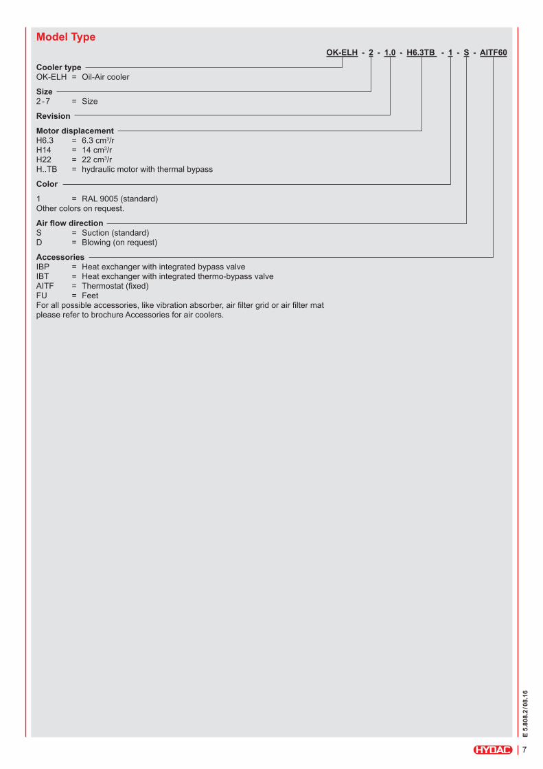
Model Type OK-ELH - 2 - 1.0 - H6.3TB - 1 - S - AITF60
Cooler typeOK-ELH = Oil-Air cooler
Size2 - 7 = Size
Revision
Motor displacement H6.3 = 6.3 cm3/r H14 = 14 cm3/r H22 = 22 cm3/r H..TB = hydraulic motor with thermal bypass
Color
1 = RAL 9005 (standard) Other colors on request.
Air flow directionS = Suction (standard) D = Blowing (on request)
Accessories IBP = Heat exchanger with integrated bypass valve IBT = Heat exchanger with integrated thermo-bypass valve AITF = Thermostat (fixed) FU = Feet For all possible accessories, like vibration absorber, air filter grid or air filter mat please refer to brochure Accessories for air coolers.

E 5.
808.
2 / 08
.16
8
DimensionsOK-ELH 2-4
[mm]A ±5
B ± 10
6.3 cc
B ± 10
14 cc
B ± 10
22 cc
C ± 5
E1 ± 5
E2 ± 5
E3 ± 5
E4 ± 2
E5 ± 2
F ø / slot
Z1
Z3
OK-ELH 2 313 270 283 283 384 199 57 324 288 80 14 x10 G1" M22x1.5
OK-ELH 3 356 279 292 292 420 230 63 370 329 100 14 x10 G1" M22x1.5 1)
OK-ELH 4 450 294 306 306 500 300 80 445 421 150 19 x10 G1" M22x1.5 2)
1) OK-ELH 3 and OK-ELH 4 have two connections M22x1.5.
[mm]A ±5
B ± 10
6.3 cc
B ± 10
14 cc
B ± 10
22 cc
C ± 5
E1 ± 5
E2 ± 5
E3 ± 5
E4 ± 5
E5 ± 5
F ø / slot
Z1
Z3
OK-ELH 5 460 311 323 338 602 350 55 495 200 2) 580 2) 12 G1-1/4" M22x1.5 2)
1) The cooling element has two connections M22x1.5.2) OK-ELH 5 has the front fixing holes in the lateral sides.
Drain portM12x1.5depth 13
(4x) M6depth 13
A/2
A
A/2
A (1 : 2.5)
E1
E2
E4A
(6x) Ø F
Ø 15
Ø 3
5
E3 B
Z3E5 E5
ROTATION
C
Z1 (2x)
AIR
AIR
HYDAC
HYDAC
OK-ELH 5
Drain portM12x1.5depth 13
4xM6 depth 5
A/2 A/2
A (1 : 2.5)
E1
E2
E4
E1A
(4x) Ø F
Ø 15
Ø 3
5
E3 B
A
Z1 (2x)Z3ROTATION
C
E5
AIR
AIR
HYDAC

E 5.
808.
2 / 08
.16
9
Note:We recommend maintaining a minimum distance to ensure an unimpeded air inlet and air outlet. This is half the height of the cooling element (A/2). Anything below the minimum distance can influence the cooling capacity and the noise emissions.
[mm]A ±5
B1 ± 10
6.3 cc
B1 ± 10
14 cc
B1 ± 10
22 cc
B2 ± 5
C ± 5
D1 ±2
D2 ±2
D3 ±2
E1 ± 5
E2 ± 5
E3 ± 5
F ø / slot
Z1
Z3
OK-ELH 6 638 378 391 405 67 598 255 482 295 497 80 98 9 G1-1/4" M22x1.5
[mm]A ±5
B1 ± 10
6.3 cc
B1 ± 10
14 cc
B1 ± 10
22 cc
B2 ± 5
C ± 5
D1 ±2
D2 ±2
D3 ±2
E1 ± 5
E2 ± 5
E3 ± 5
F ø / slot
Z1
Z3
OK-ELH 7 726 – 444 459 42 706 410 560 450 597 75 73 9x20 G1-1/4" M22x1.5
OK-ELH 6
Drain portM12x1.5depth 13
B2
A
Z3
A/2A/2
A (1 : 2.5)
E1
E2
D2
C
E3
A
(4x) Ø F
Ø 15
Z1 (3x)Top fixing points M8 (2x)
Ø 3
5
D1D3
B1
Plug
ROTATION
AIR
AIR
4xM6 depth 13
OK-ELH 7

E 5.
808.
2 / 08
.16
10
NoteThe information in this brochure relates to the operating conditions.For applications and operating conditions not described, please contact the relevant technical department.Subject to technical modifications.
Industriegebiet 66280 Sulzbach/Saar Germany
Tel.: +49 6897 509-01 Fax: +49 6897 509-454
E-mail: [email protected] Internet: www.hydac.com
Via Sceresa, Zona Industriale 3 6805 Mezzovico Switzerland
Tel.: +41 91 9355-700 Fax: +41 91 9355-701
E-mail: [email protected] Internet: www.hydac.com
HYDAC COOLING GMBH
HYDAC AG Mezzovico Branch