Air-Cooled Split System Condensing Units - Daikin...
46
Installation and Maintenance Manual IM 914-7 Group: Applied Air Systems Part Number: IM 914 Date: November 2015 Air-Cooled Split System Condensing Units for Remote DX Coils and Air Handlers Models RCS015D to 140D R-410A Refrigerant
Transcript of Air-Cooled Split System Condensing Units - Daikin...

Installation and Maintenance Manual IM 914-7Group: Applied Air SystemsPart Number: IM 914Date: November 2015
Air-Cooled Split System Condensing Units for Remote DX Coils and Air Handlers
Models RCS015D to 140D R-410A Refrigerant

IM 914-7 • AIR-COOLED CONDENSING UNIT 2 www.DaikinApplied.com
Table of ConTenTs
Table of ConTenTs
Introduction . . . . . . . . . . . . . . . . . . . . . . . . . . . . . . . . . 3Mechanical Installation . . . . . . . . . . . . . . . . . . . . . . . . 4
Low Ambient Capability . . . . . . . . . . . . . . . . . . . . . . 4Receiving Inspection . . . . . . . . . . . . . . . . . . . . . . . . 4Codes and Regulations . . . . . . . . . . . . . . . . . . . . . . 4Unit Placement . . . . . . . . . . . . . . . . . . . . . . . . . . . . 4Clearances . . . . . . . . . . . . . . . . . . . . . . . . . . . . . . . 4Rigging and Handling . . . . . . . . . . . . . . . . . . . . . . . 5Spring Isolation and Corner Weights . . . . . . . . . . . 6Refrigerant Piping . . . . . . . . . . . . . . . . . . . . . . . . . . 7
Electrical Installation . . . . . . . . . . . . . . . . . . . . . . . . . 14Field Power Wiring . . . . . . . . . . . . . . . . . . . . . . . . 14Controls . . . . . . . . . . . . . . . . . . . . . . . . . . . . . . . . . 15
Wiring Diagrams . . . . . . . . . . . . . . . . . . . . . . . . . . . . . 16Unit Options . . . . . . . . . . . . . . . . . . . . . . . . . . . . . . . . 23
Optional Low Ambient Compressor Operation . . . 23Optional Hot-Gas Bypass (HGBP) . . . . . . . . . . . . 23Optional Vandal Guards . . . . . . . . . . . . . . . . . . . . 24
Check, Test, and Start Procedures . . . . . . . . . . . . . . 25Servicing Control Panel Components . . . . . . . . . . 25Refrigerant Piping Checkout . . . . . . . . . . . . . . . . . 26Electrical Checkout . . . . . . . . . . . . . . . . . . . . . . . . 26Compressor Startup . . . . . . . . . . . . . . . . . . . . . . . 26Crankcase Heaters . . . . . . . . . . . . . . . . . . . . . . . . 26Condenser Fan Blades . . . . . . . . . . . . . . . . . . . . . 27Scroll Compressor Rotational Direction . . . . . . . . . 27Thermostatic Expansion Valve . . . . . . . . . . . . . . . 27Oil Levels . . . . . . . . . . . . . . . . . . . . . . . . . . . . . . . 28System Adjustment . . . . . . . . . . . . . . . . . . . . . . . . 28Liquid Line Sight Glass and Moisture Indicator . . . 28Refrigerant Charging . . . . . . . . . . . . . . . . . . . . . . . 28
Operation . . . . . . . . . . . . . . . . . . . . . . . . . . . . . . . . . . . 29Condenser Fan Arrangement . . . . . . . . . . . . . . . . 29
Maintenance . . . . . . . . . . . . . . . . . . . . . . . . . . . . . . . . 30Servicing Control Panel Components . . . . . . . . . . 30Unit Storage . . . . . . . . . . . . . . . . . . . . . . . . . . . . . 30Scroll Compressor Piping . . . . . . . . . . . . . . . . . . . 31All-Aluminum Condenser Coils . . . . . . . . . . . . . . . 32Cleaning Option E Coated Coils . . . . . . . . . . . . . . 33Servicing Refrigerant Sensors or Switches . . . . . . 34Control Panel Components . . . . . . . . . . . . . . . . . . 34
Service and Warranty Procedure . . . . . . . . . . . . . . . 39Replacement Parts . . . . . . . . . . . . . . . . . . . . . . . . 39
Limited Product Warranty . . . . . . . . . . . . . . . . . . . . . 41RCS Condensing Equipment Warranty Registration Form . . . . . . . . . . . . . . . . . . . 42Quality Assurance Survey Report . . . . . . . . . . . . . . 44

InTroduCTIon
www.DaikinApplied.com 3 IM 914-7 • AIR-COOLED CONDENSING UNIT
InTroduCTIon
Daikin air-cooled condensing units are complete, self-contained automatic refrigerating units. Every unit is completely assembled, factory wired, and tested. Each unit consists of air cooled condensers, Copeland Compliant Scroll® hermetic compressor, and internal refrigerant piping, ready to be piped to a field-supplied evaporator and liquid line accessories.
The electrical control center includes all equipment protection and operating controls necessary for automatic operation, except staging control for the steps of capacity in the unit. Condenser fan motors are three-phase and are started by their own contactors with inherent overload protection. The compressor has both current sensing and thermal overload protection.
This equipment is to be installed by qualified personnel who are experienced with this type of equipment and familiar with local codes and regulations. Carefully read all instructions and take into account any special considerations prior to installing the unit. Give this manual to the owner and explain its provisions.
Unit Nameplate The unit nameplate is located on both the interior and exterior of the main controls. It includes the unit model number, serial number, unit performance, and electrical characteristics.
Important Message to the Owner Read these instructions carefully and keep them near the product for future reference. Although these instructions are addressed primarily to the installer, useful maintenance information is included. Have the installer acquaint you with the operation of the product and periodic maintenance requirements.
Recognize Safety Symbols, Words, and Labels It is the owner’s and installer’s responsibility to read and comply with all safety information and instructions, as well as the accompanying hazard identification symbols (see below).
Failing to follow safety information increases the risk of property damage and/or product damage, serious personal injury, or death. Improper installation, operation or maintenance can void the warranty.
Hazard Identification Information The following symbols and labels are used throughout this manual to indicate immediate or potential hazards.
WARNINGWarnings indicate potentially hazardous situations, which can result in property damage, severe personal injury, or death if not avoided.
CAUTIONCautions indicate potentially hazardous situations, which can result in personal injury or equipment damage if not avoided.
DANGERDangers indicate a hazardous situation which will result in death or serious injury if not avoided
Agency Listed
Nomenclature
US
RCS – 080 – D
Rooftop Condensing System
Nominal capacity (tons) 015, 020, 025, 030, 035, 040, 045, 050, 062, 072, 080, 092, 100, 110, 120, 125, 140
Design vintage

IM 914-7 • AIR-COOLED CONDENSING UNIT 4 www.DaikinApplied.com
MeChanICal InsTallaTIon
MeChanICal InsTallaTIon
Low Ambient Capability Low head pressure may lead to poor, erratic refrigerant feed control at the thermostatic expansion valve. The units have automatic control of the condenser fans which should provide adequate head pressure control down to:
1. 50°F (10°C) as standard.
2. 0°F (-17°C) with option (see Optional Low Ambient Compressor Operation on page 23) provided the unit is not exposed to windy conditions.
NOTE: The system designer is responsible for assuring the condensing unit is not exposed to excessive wind or air recirculation.
Receiving Inspection CAUTION
Sharp edges on sheet metal and fasteners can cause personal injury. This equipment must be installed, operated, and serviced only by an experienced installation company and fully trained personnel.
When the equipment is received, all items should be carefully checked against the bill of lading to be sure all crates and cartons have been received. If the unit has become dirty during shipment (winter road chemicals are of particular concern), clean it when received.
All units should be inspected carefully for damage when received. Report all shipping damage to the carrier and file a claim. In most cases, equipment ships F.O.B. factory and claims for freight damage should be filed by the consignee. Before unloading the unit, check the unit nameplate to make sure the voltage complies with the power supply available.
Codes and Regulations IMPORTANT
The United States Environmental Protection Agency (EPA)regulations cover introduction and disposal of refrigerants in this unit. Failure to follow those regulations can harm the environment and lead to substantial fines. Because regulation scan change, a certified technician should perform any work done on this unit. If you have any questions, please contact the local office of the EPA.
This product is designed and manufactured to permit installation in accordance with National Codes. System design should, where applicable, follow information presented in accepted industry guides such as the ASHRAE Handbooks. It is the installer’ s responsibility to install the product in accordance with National Codes and/or prevailing local code sand regulations. The manufacturer disclaims all responsibility for equipment installed in violation of any code or regulations
Unit Placement RCS units are for outdoor applications and can be mounted either on a roof or at ground level. The foundation must be strong enough to support the unit weight.
For roof mounted applications, install the unit on a steel channel or I-beam frame to support the unit above the roof.
For ground level applications, install the unit on a substantial base that will not settle. A one-piece concrete slab with footings extended below the frost line is recommended. Be sure the foundation is level within 1/2ʺ (13mm) over its length and width.
Clearances Do not block the flow of air to and from the condenser coil(see Figure 1, Figure 2, and Figure 3). Restricting airflow or allowing air recirculation will result in a decrease in unit performance and efficiency because discharge pressures are increased. There must be no obstruction above the unit that would deflect discharge air downward where it could be recirculated back to the inlet of the condenser coil.
The condenser fans are propeller type and will not operate with ductwork.
Install the unit with enough side clearance for air entrance to the coil and for servicing. Provide service access to the compressors, electrical control panel and piping components. Do not allow debris to accumulate near the unit where it could be drawn into the condenser coil. Keep condenser coils and fan discharge free of snow or other obstructions to permit adequate airflow for proper operation.
Figure 1: RCS Service Clearances
MeChanICal InsTallaTIon
www.DaikinApplied.com 5 IM 914-7 • AIR-COOLED CONDENSING UNIT
Figure 2: RCS Side-by-Side Service Clearances
Figure 3: RCS Pit Service Clearances Rigging and Handling WARNING
Use all lifting points. Improper lifting can cause severe personal injury and property damage.
Lifting brackets with 2ʺ (51 mm) diameter holes are provided on the sides of the unit.
Use spreader bars (Figure 4), 96ʺ to 100ʺ (2438 to 2540 mm) wide, to prevent damage to the unit cabinet. Avoid twisting or uneven lifting of the unit. The cable length from the bracket to the hook should always be longer than the distance between the outer lifting points.
Figure 4: RCS Lifting Points
*Condenser coil replacement issimplified if the following access
can be if the need arises:015D-025D – 61ʺ030D-062D – 83ʺ072D-100D – 106ʺ110D-140D – 38ʺ

IM 914-7 • AIR-COOLED CONDENSING UNIT 6 www.DaikinApplied.com
MeChanICal InsTallaTIon
Spring Isolation and Corner Weights The sum of the corner weights (Table 1) exceeds the total weight by about 10% to allow a safety factor in spring selections.
Figure 5: Spring Mounting Hole Locations
Table 1: Corner Weights (refer to Figure 5)
Unit Size
Weight #1 (lbs)
Weight #2 (lbs)
Weight #3 (lbs)
Weight #4 (lbs)
015 408 571 399 559020 427 583 434 593025 445 563 455 575030 540 706 492 644035 624 770 593 731040 632 776 600 737045 632 729 630 726050 617 732 615 730062 654 766 652 764072 872 1048 882 1060080 846 1029 919 1118085 866 1034 939 1134092 903 1083 978 1173100 903 1083 978 1173110 1075 1321 1031 1266120 1144 1377 1275 1535125 1389 1645 1344 1592130 1413 1671 1369 1620140 1422 1678 1407 1661

MeChanICal InsTallaTIon
www.DaikinApplied.com 7 IM 914-7 • AIR-COOLED CONDENSING UNIT
Refrigerant Piping IMPORTANT
A qualified Architect or Systems HVAC Design Engineer familiar with refrigerant piping design, as well as local codes and regulations, must provide refrigerant piping design. The following manufacturer recommendations serve as a general guide and should not replace a qualified professional’s refrigerant piping system design
All field piping, wiring, and procedures must be performed in accordance with ASHRAE, EPA, and industry standards. Proper refrigerant piping can make the difference between a reliable system and an inefficient, problematic system.
The primary concerns related to piping are refrigerant pressure drop, a solid liquid feed to the expansion valves, continuous oil return, and properly sized refrigerant specialties.
Insulate the suction line to reduce excessive superheat buildup. Insulate the liquid line when located in areas above ambient temperature to prevent loss of subcooling and consequent liquid flashing.
The recommended source for refrigerant piping techniques and sizing is Daikin AG31-011 Refrigerant Piping Design Guide. Regarding hot gas bypass for RCS Condensing Units with micro-channel condensers; hot gas bypass installation must be in accordance with page 23 and page 24 in this manual.
Although conflicting piping recommendations can be found in different sources, Daikin offers the following recommendations for these controversial issues.
The use of double risers for vertical gas risers is generally not required and should be used only as a last resort to maintain the minimum refrigerant flow to carry oil up the vertical risers. Slightly downsizing the vertical riser is a preferable option to providing double risers.
Slope the refrigerant lines 1ʺ per 10 feet of horizontal run in the direction of refrigerant flow to assist oil return.
Resist using hot gas bypass for applications when operation in ambient temperature below 40 degrees is expected. This recommendation helps to maintain adequate condensing pressures and liquid refrigerant at the expansion valve when condenser capacities are at their maximum.
Pressure drops in the refrigerant lines should be maintained at or below the ASHRAE recommendations and line lengths should be made as short as possible. Exceeding these recommendations will decrease performance and could impact reliability.
Small traps should be provided at the base of each major vertical gas riser to assist in the collection of oil. If vertical risers exceed more than 25 feet, install a small trap at the midpoint and at a maximum of 20 foot intervals.
Use caution in sizing the liquid line in applications where the evaporator is above the outdoor section. The weight of the liquid refrigerant in the vertical column will decrease the pressure at the top of the riser (approximately 0.5 psi per foot of vertical rise) allowing some of the refrigerant to flash to a gas. Adequate refrigerant subcooling is needed at the outdoor section to prevent large volumes of refrigerant gas at the expansion valve.
The piping systems should always extend above the highest component in the refrigeration system before dropping down to make the final refrigerant connections to components. This practice will hinder the draining of condensed refrigerant to the lower component when normal shutdown procedures do not occur (such as a power failure). NOTE: Do not run refrigerant lines underground.
Special care is needed for applications where the evaporator is above the condensing unit. Check valves should be installed to prevent liquid line refrigerant from condensing, draining back to the condenser and causing high pressure trips when the compressors start up.

IM 914-7 • AIR-COOLED CONDENSING UNIT 8 www.DaikinApplied.com
MeChanICal InsTallaTIon
Piping Locations NOTE: Piping locations are symmetrical on both sides
Figure 6: Refrigerant Piping Connection Locations Example (040 Shown)
Table 2: 015D – 140D Connection Locations
Component CircuitConnection Location (refer to Figure 6)
015D 020D 025D 030D 035D 040D 045D 050D 062DS1 Suction line #1 Ckt.1 32.1 32.1 32.1 29.3 29.3 29.3 29.4 29.4 29.4S2 Suction line #2 Ckt.2 32.1 32.1 32.1 29.3 29.3 29.3 29.4 29.4 29.4L1 Liquid line #1 Ckt.1 16.7 16.7 16.7 12.9 12.9 12.9 12.0 12.0 12.0L2 Liquid line #2 Ckt.2 16.7 16.7 16.7 12.9 12.9 12.9 12.0 12.0 12.0
HG1 HGBP line #1 Ckt.1 24.0 24.0 24.0 25.4 25.4 25.4 25.9 25.9 25.9HG2 HGBP line #2 Ckt.2 24.0 24.0 24.0 25.4 25.4 25.4 25.9 25.9 25.9
Component CircuitConnection Location (refer to Figure 6)
072D 080D 092D 100D 110D 120D 125D 140DS1 Suction line #1 Ckt.1 32.3 32.3 32.3 32.3 32.4 32.4 32.4 32.4S2 Suction line #2 Ckt.2 32.3 32.3 32.3 32.3 32.4 32.4 32.4 32.4L1 Liquid line #1 Ckt.1 13.5 11.2 11.2 11.2 20.8 20.8 20.8 20.8L2 Liquid line #2 Ckt.2 13.5 11.2 11.2 11.2 20.8 20.8 20.8 20.8
HG1 HGBP line #1 Ckt.1 25.9 28.1 28.1 28.1 25.9 25.9 25.9 25.9HG2 HGBP line #2 Ckt.2 25.9 28.1 28.1 28.1 25.9 25.9 25.9 25.9

MeChanICal InsTallaTIon
www.DaikinApplied.com 9 IM 914-7 • AIR-COOLED CONDENSING UNIT
Piping Connections/Sizes
Figure 7: Refrigerant Piping Connections Example (080D Shown)
Table 3: 015D – 140D Connection Sizes
Component Circuit (Figure 7)Figure 7 Tubing
015D 020D 025D 030D 035D 040D 045D 050D 062DS1 Suction line #1 Ckt.1 1.12 1.38 1.62 1.62 1.62 1.62 1.62 2.12 2.12S2 Suction line #2 Ckt.2 1.12 1.38 1.62 1.62 1.62 1.62 1.62 2.12 2.12L1 Liquid line #1 Ckt.1 0.62 0.62 0.88 0.88 0.88 0.88 0.88 0.88 0.88L2 Liquid line #2 Ckt.2 0.62 0.62 0.88 0.88 0.88 0.88 0.88 0.88 0.88
HG1 HGBP line #1 Ckt.1 0.88 0.88 0.88 0.88 0.88 0.88 0.88 0.88 0.88HG2 HGBP line #2 Ckt.2 0.88 0.88 0.88 0.88 0.88 0.88 0.88 0.88 0.88
Component Circuit (Figure 7)Figure 7 Tubing
072D 080D 092D 100D 110D 120D 125D 140DS1 Suction line #1 Ckt.1 2.12 2.12 2.12 2.62 2.62 2.62 2.62 2.62S2 Suction line #2 Ckt.2 2.12 2.12 2.12 2.62 2.62 2.62 2.62 2.62L1 Liquid line #1 Ckt.1 0.88 1.12 1.12 1.12 1.12 1.12 1.12 1.12L2 Liquid line #2 Ckt.2 0.88 1.12 1.12 1.12 1.12 1.12 1.12 1.12
HG1 HGBP line #1 Ckt.1 0.88 0.88 0.88 0.88 0.88 0.88 0.88 0.88HG2 HGBP line #2 Ckt.2 0.88 0.88 0.88 0.88 0.88 0.88 0.88 0.88
Piping Circuitry Figure 8: Circuit Schematic

IM 914-7 • AIR-COOLED CONDENSING UNIT 10 www.DaikinApplied.com
MeChanICal InsTallaTIon
Pumpdown The pumpdown capacity of RCS units is less than the system charge. If the low side of the refrigeration circuit must be opened, then the low side operating charge must first be reclaimed.
Holding Charge DANGER
Before applying heat to remove brazed piping caps and plugs, always vent piping to atmosphere. Failure to do so will cause hazardous pressures, explosion, severe personal injuries, or death.
The RCS unit ships with a nitrogen holding charge. At the time the unit is received, a visual inspection of the unit piping should be made to be sure no breakage occurred or that the fittings did not loosen during shipping. A pressure test on the RCS units should indicate a positive pressure in the unit. If no pressure is evident, the unit must be leak tested and the leak repaired. Note and report this to the Daikin sales representative and freight carrier (if the loss is due to shipping damage).
Vent to atmosphere by opening gauge ports at the compressors and liquid line shutoff valves. Make sure manual valves are not back seated to shut off the gauge ports.
Leak Testing WARNING
Do not use oxygen or air to build up pressure. Explosion hazard can cause severe personal injury or death.
If loss of the nitrogen holding charge occurs, the unit should be checked for leaks prior to charging the complete system. If the full charge was lost, leak testing can be done by charging the refrigerant into the unit build the pressure to approximately 10 psig and adding sufficient dry nitrogen to bring the pressure to a maximum of 125 psig The unit should then be leak tested with a halide or electronic leak detector. After making any necessary repair, the system should be evacuated as described.
Evacuation CAUTION
Before replacing refrigerant sensors or protective devices, see “Refrigerant Charge” on page 13 for an important warning to prevent an abrupt loss of the entire charge.
CAUTIONTo service liquid line components, the manual shutoff valve is closed and refrigerant is pumped into the condenser. The pounds of refrigerant in the system may exceed the capacity of the condenser, depending on the amount of refrigerant in the liquid lines. Suitable means of containing the refrigerant is required.
After determining the unit is tight and there are no refrigerant leaks, evacuate the system. Use a vacuum pump with a pumping capacity of approximately 3 cu.ft./min. and the ability to reduce the vacuum in the unit to at least 1 mm (1000 microns).
1. Connect a mercury manometer or an electronic gauge (or other type of micron gauge) to the unit at a point remote from the vacuum pump. For readings below 1 millimeter, use an electronic or other micron gauge.
2. Use the triple evacuation method which is particularly helpful if the vacuum pump is unable to obtain the desired 1 mm of vacuum. The system is first evacuated to approximately 29ʺ (740 mm) of mercury. Then add enough refrigerant vapor to the system to bring the pressure up to 0 pounds (0 microns).
3. Evacuate the system again to 29ʺ (740 mm) of vacuum. Repeat his procedure three times. This method is most effective by holding system pressure at 0 pounds (0 microns) for a minimum of 1 hour between evacuations. The first pulldown removes about 90% of the noncondensables; the second removes about 90% of that remaining from the first pulldown. After the third pulldown, only 1/10 of 1% of noncondensables remains.
Table 6 on page 12 shows the relationship between pressure, microns, atmospheres, and the boiling point of water.

MeChanICal InsTallaTIon
www.DaikinApplied.com 11 IM 914-7 • AIR-COOLED CONDENSING UNIT
Table 4: Approximate R-410A Refrigerant Charge per Circuit, 015D to 140D
Unit SizeRCS Operating Charge
Circuit #1 Circuit #2015D 8.35 8.45020D 9.05 8.95025D 8.0 8.2030D 9.6 10.0035D 10.4 11.1040D 10.8 11.5045D 12.6 13.0050D 12.6 13.0062D 12.7 13.2072D 15.1 16.2080D 19.0 20.5092D 19.2 20.7100D 19.2 20.7110D 29.1 31.6120D 29.1 34.7125D 32.3 34.7140D 32.3 37.1
Table 5: Weight of Refrigerant in Copper Lines (Pounds per 100 feet of Type L Tubing)
O .D . line size Vol . per 100 ft in cubic feet
Weight of refrigerant, lbs ./100 feetLiquid @110°F
(Subcool to 15°F)Hot gas@127°F cond . (Superheat to 85°F)
Suction gas (superheat to 10°F)
R-410A R-410A 40°F, R-410A3/8ʺ 0.054 3.22 0.36 0.1311/2ʺ 0.100 5.97 0.67 0.2435/8ʺ 0.162 9.67 1.08 0.3947/8ʺ 0.336 20.06 2.24 0.816
1-1/8ʺ 0.573 34.21 3.82 1.391-3/8ʺ 0.872 52.06 5.81 2.111-5/8ʺ 1.237 73.85 8.24 3.002-1/8ʺ 2.147 128.18 14.30 5.222-5/8ʺ 3.312 197.73 22.06 8.053-1/8ʺ 4.728 282.26 31.49 11.493-5/8ʺ 6.398 381.96 42.61 15.554-1/8ʺ 8.313 496.29 55.36 20.20

IM 914-7 • AIR-COOLED CONDENSING UNIT 12 www.DaikinApplied.com
MeChanICal InsTallaTIon
Table 6: Pressure - Vacuum Equivalents
Absolute pressure above zero Vacuum below 1 atmosphere Approximate fraction of 1 atmosphere
H2O boiling point at each pressure (0°F)Microns PSIA Mercury, in . (mm)
0 0 760.00 (29.921) — —50 0.001 759.95 (29,920) 1/15,200 –50
100 0.002 759.90 (29.920) 1/7,600 –40150 0.003 759.85 (29.920) 1/5,100 –33200 0.004 759.80 (29.910) 1/3,800 –28300 0.006 759.70 (29.910) 1/2,500 –21500 0.009 759.50 (29.900) 1/1,520 –12
1,000 0.019 759.00 (29.880) 1/760 12000 0.039 758.00 (29.840) 1/380 154,000 0.078 756.00 (29.760) 1/189 296000 0.117 754.00 (29.690) 1/127 398,000 0.156 752.00 (29.600) 1/95 4610,000 0.193 750.00 (29.530) 1/76 5215,000 0.290 745.00 (29.330) 1/50 6320,000 0.387 740.00 (29.130) 1/38 7230,000 0.580 730.00 (28.740) 1/25 8450,000 0.967 710.00 (27.950) 1/15 101100,000 1.930 660.00 (25.980) 2/15 125200,000 3.870 560.00 (22.050) 1/4 152500,000 9.670 260.00 (10.240) 2/3 192760,000 14.697 0 1 atmosphere 212
Charging the System CAUTION
Adding refrigerant to the suction always risks liquid-related damage to the compressor.
CAUTIONUnits must be charged only with R-410A . Field mixing or changing of refrigerants can compromise performance and damage equipment.
RCS units are leak tested at the factory and shipped with a nitrogen holding charge. If the holding charge has been lost due to shipping damage, charge the system with enough refrigerant to raise the unit pressure to 30 psig after first repairing the leaks and evacuating the system.
1. After all refrigerant piping is complete and the system is evacuated, it can be charged as described in the paragraphs following. Connect the refrigerant drum to the gauge port on the liquid shutoff valve and purge the charging line between the refrigerant cylinder and the valve. Then open the valve to the mid position.
2. If the system is under a vacuum, stand the refrigerant drum with the connection up, open the drum, and break the vacuum with refrigerant gas.
3. With a system gas pressure higher than the equivalent of a freezing temperature, invert the charging cylinder and elevate the drum above the condenser. With the drum in this position and the valves open, liquid refrigerant flows into the condenser. Approximately 75% of the total requirement estimated for the unit can be charged in this manner.
4. After 75% of the required charge enters the condenser, reconnect the refrigerant drum and charging line to the suction side of the system. Again, purge the connecting line, stand the drum with the connection side up, and place the service valve in the open position.
Important: At this point, interrupt the charging procedure and do prestart checks before attempting to complete the refrigerant charge. NOTE: Stamp the total operating charge per circuit on the
unit nameplate for future reference.
Carefully and slowly add refrigerant to the suction to prevent damage. Adjust the char ng tank hand valve so that liquid leaves the tank but vapor enters the compressor.
Table 7: Acceptable Refrigerant Oils
Polyolester [POE] OilsCopeland ULtra 22 CC
Mobil EAL™ Arctic 22 CCICI EMKARATE RL™ 32CL
Note: Do not use mineral oils with R-410A.

MeChanICal InsTallaTIon
www.DaikinApplied.com 13 IM 914-7 • AIR-COOLED CONDENSING UNIT
Refrigerant Charge Each unit is designed for use with R-410A. The total charge per circuit is the sum of the following values:
• Condenser section charge - Refer to manufacturer’s data, see Table 4 on page 11.
• Evaporator coil charge - Refer to manufacturer’s data. • Charge for length of unit piping to the evaporator coil -
see Table 4. • Charge for length of interconnecting piping between the
RCS unit (installed by field) - see Table 5 on page 11. The exact charge for a one piece RCS is on the unit nameplate. Approximate values are shown in Table 4.
Field Charging Procedure Under normal (summertime) operating conditions, the superheat at the compressor should be between 8ºF and 14ºF and subcooling measured at the condenser outlet should be 15ºF (nominal).
With all compressors operating at full capacity, a 25ºF-35ºF temperature difference should exist between the entering condenser air and the temperature corresponding to the compressor saturated discharge pressure.
The recommended method for field charging would be to recover, evacuate and re-charge the system to the value on the unit nameplate. If this method is not practical or verification of charge is the purpose, then unit charge can best evaluated by the amount of subcooling.
Follow Table 8 for acceptable subcooling levels. To calculate subcooling: take the difference between the liquid temperature leaving the condenser and the temperature corresponding to the compressor saturated discharge pressure. It is important not to use the saturation pressure at the condenser outlet as this will lead to an overcharged state . When charging at ambients below 75ºF it is strongly recommended to recover, evacuate and re-charge the unit to the value on the unit nameplate.
Table 8: Typical Subcooling Operating Values
Outdoor Ambient Subcooling Range (see notes)75–85ºF 5–10ºF85–95ºF 10–15ºF95–105ºF 15–20ºF
1. All compressors in circuit operating at full capacity 2. All condenser fans operating 3. Speedtrol condenser fan motor(s) operating at 100% (if option present) 4. Hot Gas Bypass not operating 5. MHGRH and liquid subcooling should not be operating
These units contain a microchannel condenser and the internal volume of the refrigeration system is less than that compared to a typical fin-tube condenser. Unit refrigerant charge can be as much as 40% less with microchannel and is much more sensitive to charge levels. Caution should be exercised not to overcharge the unit.
Refrigeration Service Valves (Standard) RCS units have the following:
One liquid line charging/evacuation valve is provided per refrigeration circuit, located at end of condensing section opposite condenser control box.
Optional valves— one discharge valve for each refrigerant circuit; located between the compressors and condenser. One suction valve for each refrigerant circuit; located between the compressors and the evaporator.
Before attempting to start the compressors, all refrigeration service valves must be fully opened and backseated.

IM 914-7 • AIR-COOLED CONDENSING UNIT 14 www.DaikinApplied.com
eleCTrICal InsTallaTIon
eleCTrICal InsTallaTIon
Field Power Wiring Wiring must comply with all applicable codes and ordinances. The warranty is voided if wiring is not in accordance with these specifications. An open fuse, tripped circuit breaker, or Manual Motor Protector (MMP) indicates a short, ground, or overload. Before replacing a fuse, circuit breaker, MMP, or restarting a compressor or fan motor, identify the trouble and correct.
According to the National Electrical Code, a disconnecting means shall be located within sight of and readily accessible from the air conditioning equipment. The unit can be ordered with an optional factory mounted disconnect switch. This switch is not fused. Power leads must be over-current protected at the point of distribution. The maximum allowable overcurrent protection (MROPD) appears on the unit nameplate.
In compliance with the National Electrical Code, an electrically isolated 115 V circuit is provided in the unit to supply the factory mounted service receptacle outlet. This circuit is powered in one of two ways.
1. Field connected, 15 amp, 115 volt power supply.
2. Select the factory powered option when the unit is ordered.
Leads are brought into the RCS unit through a 7/8ʺ knockout in the bottom of the main control panel, near the power wire entry point (Figure 9). Several appropriately sized hubs are provided to allow the field to expand the pilot holes as required.
Figure 9: RCS 080D - 100D Field Wiring
Table 9: Recommended 3-Phase Power Wiring to Ensure Disconnects and Power Blocks Mate with Power Wiring
Wire gauge Qty ./pole Insulation
rating (°C)No . of
conduitsConduit (trade
size, in .)
For MCA up to
(amps)10 1 75 1 1/2 358 1 75 1 3/4 506 1 75 1 1 654 1 75 1 1-1/4 853 1 75 1 1-1/4 1002 1 75 1 1-1/4 1151 1 75 1 1-1/4 130
1/0 1 75 1 1-1/2 1502/0 1 75 1 2 1753/0 1 75 1 2 2004/0 1 75 1 2 230250 1 75 1 2-1/2 255300 1 75 1 2-1/2 285350 1 75 1 3 310400 1 75 1 3 335500 1 75 1 3 3803/0 2 75 2 2 4004/0 2 75 2 2 460250 2 75 2 2-1/2 510300 2 75 2 2-1/2 570350 2 75 2 3 620400 2 75 2 3 670500 2 75 2 3 760250 3 75 3 2-1/2 765300 3 75 3 2-1/2 855350 3 75 3 3 930
1. All wire sizes assume separate conduit for each set of parallel conductors. 2. All wire sizes based on NEC Table 310-16 for 75°C THW wire (copper). Canadian
electrical code wire ampacities may vary. 3. All wire sizes assume no voltage drop for short power leads.

eleCTrICal InsTallaTIon
www.DaikinApplied.com 15 IM 914-7 • AIR-COOLED CONDENSING UNIT
Controls The primary requirements for condensing unit controls are to maintain proper entering and leaving temperatures. Details vary with each job and are related to design saturated suction temperatures and conditioned air temperature.
Recommended Temperature Control If the project design conditions are:
1. 74-84 EDB and 62-70 EWB
2. 52-57 LAT off the DX coil
3. 42-48 SST
4. Constant volume space or return air temperature control
Then:
1. Compressors can be sequenced to maintain design space temperatures ± about 1.5 degrees dB. If excessive cycling occurs, then:
a. The sensor location is suspect or air changes are unusually high.
b. Consider widening the space temperature control range beyond ± 1.5 degrees.
2. A warning should be generated if LAT drops more than seven degrees below design.
3. HGBP is desired and allows even lower LAT limits.
To minimize compressor cycling, the controls must include (at minimum) three minute anti-cycling timers on the condensing unit. Suggested programmable controls include additional time delay logic.
1. Minimum OFF time for a stage is five minutes
2. Minimum ON time for a stage is five minutes (unless an alarm occurs).
For additional control information and compressor staging, refer to IM 919-1.

IM 914-7 • AIR-COOLED CONDENSING UNIT 16 www.DaikinApplied.com
WIrIng dIagraMs
WIrIng dIagraMs
Figure 10: Typical RCS D Vintage Controls Wiring Diagram (115V Field Connections, No Speedtrol)

WIrIng dIagraMs
www.DaikinApplied.com 17 IM 914-7 • AIR-COOLED CONDENSING UNIT
Figure 10 continued: Typical RCS D Vintage Controls Wiring Diagram (115V Field Connections, No Speedtrol)

IM 914-7 • AIR-COOLED CONDENSING UNIT 18 www.DaikinApplied.com
WIrIng dIagraMs
Figure 11: Typical RCS D Vintage Controls Wiring Diagram (24V Field Connections with Speedtrol)

WIrIng dIagraMs
www.DaikinApplied.com 19 IM 914-7 • AIR-COOLED CONDENSING UNIT
Figure 11 continued: Typical RCS D Vintage Controls Wiring Diagram (24V Field Connections with Speedtrol)

IM 914-7 • AIR-COOLED CONDENSING UNIT 20 www.DaikinApplied.com
WIrIng dIagraMs
Figure 12: Typical RCS D Vintage Power Wiring Diagram (No Speedtrol with GFI and Phase Voltage Option)

WIrIng dIagraMs
www.DaikinApplied.com 21 IM 914-7 • AIR-COOLED CONDENSING UNIT
Figure 13: Typical RCS D Vintage Power Wiring Diagram (with Speedtrol)

IM 914-7 • AIR-COOLED CONDENSING UNIT 22 www.DaikinApplied.com
WIrIng dIagraMs
Figure 14: Typical RCS D Vintage Power Wiring Diagram (with New Powered Receptacle Option and No Speedtrol)

unIT opTIons
www.DaikinApplied.com 23 IM 914-7 • AIR-COOLED CONDENSING UNIT
unIT opTIons
Optional Low Ambient Compressor Operation The SpeedTrol throttling range is 250 to 400 psig, fixed. The SpeedTrol fan motor is a three-phase motor, identical to the unit voltage (208 V to 575 V) and is controlled by a variable frequency drive (Figure 15). The variable frequency drive receives a signal from a pressure transducer and varies the condenser fan speed accordingly.
The pressure transducer is calibrated to provide a 1.0 to 5.0 V (dc) signal with a 8 to 30 V (dc) input, starting at 1.0 V (dc) @ 250 psig and up to 5.0 V (dc) @ 400 psig. In order to maintain an acceptable condensing pressure, the VFD will modulate the motor down to a minimum of 23 Hz, and will not allow operation below this frequency level. At (or above) 400 psig the VFD will operate the motor at 60 Hz. The control band between the two frequencies (23 Hz and 60 Hz) is a linear relationship with the condensing pressure as shown in (Figure 16).
The VFDs and pressure transducers are located in the control box mounted in the condensing section. Each refrigerant circuit is independent and has its own respective VFD and pressure transducer. The SpeedTrol option operates independently of the main unit controller.
Figure 15: R-410A SpeedTrol
Figure 16: SpeedTrol Operating Characteristics
Optional Hot-Gas Bypass (HGBP) CAUTION
Do not touch the hot gas line during valve checkout. Place your hand near it to feel the heat, or use gloves. The hot gas line can become hot enough in a short time to cause personal injury.
Hot-gas bypass (Figure 17) provides protection against low suction pressure. It also helps keep the unit operating at light load without excessive cycling. The hot-gas bypass valve is shipped loose in a kit.
The system consists of a pressure regulating valve that starts to modulate open at 100 psig (32°F). The valve is fully open at 90 psig (26°F). The factory settings can be modified in the field as the valve is adjustable. NOTE: The regulating valve opening point can be determined
by slowly reducing the system load or reducing the required discharge air temperature setting while observing the suction pressure. When the bypass valve starts to open, the refrigerant line on the evaporator side of the valve will begin to feel warm as your hand approaches the copper tube.
Notes on installation: 1. Daikin provides a capped “T” on the discharge line for
field installations.
2. The field must pipe the hot gas bypass line, including the regulating valve, from the discharge “T” to the suction line.
3. The regulating valve suction port (equalizer line) must be connected to the suction line at any convenient point before the compressor.
Hot-Gas Bypass (HGBP) Installation The “D” vintage, R-410A, RCS units, with microchannel condenser coils require any hot-gas bypass to be injected into the suction line. Injecting hot-gas ahead of the refrigerant distributor will drive refrigerant out of the evaporator. The microchannel condenser coils do not have sufficient volume to accept this charge without raising the head pressure to unacceptable levels.
Bypass to Suction Line Locate the main expansion valve bulb downstream of the bypass connection as illustrated in Figure 17, with at least 3 feet of suction line, preferably with an elbow between the two locations. Locate the HGBP valve close to the discharge line takeoff. Tap the HGBP valve equalizer line into the suction line at any convenient point. The line downstream of the HGBP valve is at the suction pressure and therefore will not be subject to storing condensed refrigerant. However, if the hot gas line downstream of the bypass valve is below the connection to the suction line, then a trap and bleed (see Figure 18) should be provided for oil return during low flow periods.

IM 914-7 • AIR-COOLED CONDENSING UNIT 24 www.DaikinApplied.com
unIT opTIons
Follow all manufacturer’s procedures included in the instructions provided with the valve.
Figure 17 (piping schematic only) illustrates the general location of the discharge bypass valves in the system. Daikin recommends that recognized piping references, such as equipment manufacturers’ literature and the ASHRAE Handbook, be consulted for assistance.
Daikin is not responsible for system design, any damage arising from faulty system design, or for misapplication of its products.
Figure 17: Hot-Gas Bypass (HGBP) Diagram
Figure 18: Hot-Gas Bypass Trap and Bleed
Optional Vandal Guards Vandal Guards add a protective screen over the condensing unit openings. The screen is constructed of 12 gauge wire that has been PVC coated. The screening has a minimum spacing of 5/8ʺ.
Vandal Guard kits are also available from the parts department for field installation.
• 403909511 - RCS015D, 020D & 025D • 403909512 - RCS030D, 035D & 040D • 403909514 - RCS045D, 050D, 060D, 062D, & 068D • 403909515 - RCS070D, 072D & 075D • 403909507 - RCS080D, 085D, 090D, 100D & 105D • 403909509 - RCS110D, 120D, 125D, 130D & 140D
Figure 19: Optional Vandal Guards

CheCk, TesT, and sTarT proCedures
www.DaikinApplied.com 25 IM 914-7 • AIR-COOLED CONDENSING UNIT
CheCk, TesT, and sTarT proCedures
DANGERMoving machinery and electrical power hazards. Will cause severe personal injury or death. Disconnect and lock off al power before servicing equipment.
WARNINGSharp edges are inherent to sheet metal parts, screws, clips, and similar items. Can cause personal injury. Exercise caution when servicing equipment.
DANGERHazardous voltage. Will cause equipment damage, severe personal injury, or death Disconnect and tag out all electrical power before servicing this equipment. All start-up and service work must be performed only by trained, experienced technicians familiar with the hazards of working on this type of equipment. Bond the equipment frame to the building electrical ground through grounding terminal or other approved means.
Check, test, and start procedures must be performed only by qualified personnel who are experienced with this type of equipment and familiar with local codes and regulations.
To obtain full warranty coverage, complete the following Check, Test, and Start Procedures, sign the RCS Condensing Equipment Warranty Registration Form and the that are supplied with the unit and return them to Daikin. These forms are included on page 42 through page 44 of this manual can also be used.
A representative of the owner or the operator of the equipment should be present during start-up to receive instructions in the operation, care, and maintenance of the unit.
If the unit has a factory mounted disconnect switch, use the switch’s bypass mechanism to open the main control panel door without de-energizing the control panel.
Servicing Control Panel Components
DANGERHazardous voltage. Will cause severe injury or death. Disconnect electric power before servicing equipment. More than one disconnect may be required to de-energize the unit.
Always inspect units for multiple disconnects to ensure all power is removed from the control panel and its components before servicing.
Before Start-up 1. Verify that the unit is completely and properly installed.
2. Verify that all construction debris is removed.
3. Verify that all electrical work is complete and properly terminated.
4. Verify that all electrical connections in the unit control panel and compressor terminal box are tight, and that the proper voltage is connected.
5. Verify all nameplate electrical data is compatible with the power supply.
6. Verify the phase voltage imbalance is no greater than 10%.
7. Manually rotate all fans and verify that they rotate freely.
8. Verify that all setscrews and fasteners on the fan assemblies are still tight.
9. Before attempting to operate the unit, review the control layout description to become familiar with the control locations.
10. Review the equipment and service literature, the sequences of operation, and the wiring diagrams to become familiar with the functions and purposes of the controls and devices.
11. Determine which optional controls are included with the unit.
12. Confirm that the remote evaporator and indoor fan are operational.

IM 914-7 • AIR-COOLED CONDENSING UNIT 26 www.DaikinApplied.com
CheCk, TesT, and sTarT proCedures
Refrigerant Piping Checkout 1. Check all exposed brazed joints on the unit, as well as
any field-installed piping, for evidence of leaks. Joints can become damaged during shipping or when the unit was installed.
2. Check that all refrigerant valves are either opened or closed as required for proper operation of the unit.
3. A thorough leak test must be done using an approved electronic leak detector. Check all valve stem packing for leaks. Replace all refrigerant valve caps and tighten.
4. Check all refrigerant lines to see that they will not vibrate against each other or against other unit components and are properly supported.
5. Check all flare connections and all refrigerant threaded connectors.
6. Look for any signs of refrigerant leaks around the condenser coils and for damage during shipping or installation.
7. Leak detector is applied externally to refrigerant joints at the factory. Do not confuse this residue with an oil leak.
8. Connect refrigerant service gauges to each refrigerant circuit before starting unit.
Electrical Checkout 1. Open all electrical disconnects and check all power
wiring connections. Start at the power block and check all connections through components to and including the compressor terminals. These should be checked again after 3 months of operati and at least annually thereafter.
2. Check all control wiring and tighten all screw connections. Check plug-in relays for proper seating and that retaining clips are installed.
3. Apply power to the unit.
4. Check at the power block or disconnect for the proper voltage and for the proper voltage between phases. Check power for proper phasing using a phase sequence meter before starting unit.
5. Check for 120 V (ac) at the control transformer and at TB1A1 and TB1A5
6. Check between TB1E28 and TB1E30 for 24 V (ac) control voltage.
Compressor Startup CAUTION
Electrical power must be applied to the compressor crankcase heaters 24 hours before starting unit to expel refrigerant from the oil, otherwise compressor damage may occur.
CAUTIONLow ambient temperature hazard. Can cause compressor damage. Do not attempt to start up and check out the refrigeration system when the outdoor air temperature is below 50°F unless the unit is specially equipped for low ambient operation.
There should be adequate building load (at least 50 percent of the unit full load capacity) to properly check the operation of the unit’s refrigerant circuits.
Record all operating parameters required by the RCS Condensing Equipment Warranty Registration Form on page 42 Return this information within 10 working days to Daikin as instructed on the form to register the start-up date with the Daikin Warranty Department.
Confirm that the remote evaporator and indoor fan are operational.
The unit is shipped with refrigeration service valves closed. Backseat (open) the discharge and liquid line valves. Connect service gauges and crack the valves off the backseat position (one turn forward). Verify that the unit has not lost its refrigerant charge.
Check the compressor oil level before startup. The oil level should be at or slightly above the center of the sight glass.
Crankcase Heaters The scroll compressors are equipped with externally mounted band heaters located at the oil sump level. The function of the heater is to keep the temperature in the crankcase high enough to prevent refrigerant from migrating to the crankcase and condensing in the oil during off-cycle.
Verify that the crankcase heaters are operating. These should operate for at least 24 hours before starting the compressors.

CheCk, TesT, and sTarT proCedures
www.DaikinApplied.com 27 IM 914-7 • AIR-COOLED CONDENSING UNIT
Condenser Fan Blades Verify that the condenser fan blades are positioned properly and that the screws are tight (see Figure 22). The fan blade must be correctly positioned within its orifice for proper airflow across the condenser coils.
Figure 20: Condenser Fan Blade Positioning
Scroll Compressor Rotational DirectionScroll compressors only compress in one rotational direction. Three-phase compressors rotate in either direction depending upon phasing of the power to L1, L2, and L3. Since there is a 50/50 chance of connecting power to cause rotation in the reverse direction, verify that the compressor rotates in the proper direction after the system is installed. If the compressor is rotating properly, suction pressure drops and discharge pressure rises when the compressor is energized. If the compressor is rotating in reverse, the sound level is louder and current draw is reduced substantially. After several minutes of operation, the compressor’s internal protector trips.
All three-phase compressors are wired the same internally. Therefore, once the correct phasing is determined for a specific system or installation, connecting properly phased power leads to the same terminals should maintain proper rotation direction.
Thermostatic Expansion Valve The field provided and installed expansion valve performs one specific function. It keeps the evaporator supplied with the proper amount of refrigerant to satisfy the load conditions.
The sensing bulb of the expansion valve should be installed in the closest straight and horizontal run of suction line from the evaporator. The bulb is insulated to reduce the effect of surrounding ambient temperatures and should be held on by clamps around the suction line. If the bulb must be removed, simply slit the insulation on each side of the bulb, remove the clamps, and then remove the capillary tubing that runs along the suction line from the valve.
The power element should be removable from the valve body without removing the valve from the line. NOTE: Before adjusting superheat, check that the unit
charge is correct, the liquid line sight glass is full with no bubbles, and that the circuit is operating under stable, full load conditions.
Expansion Valve Superheat Adjustment It is important that the expansion valve superheat setting be adjusted to be between 8°F (-13°C) and 14°F (-10°C). Insufficient superheat will cause liquid floodback to the compressor which may result in slugging. Excessive superheat will reduce system capacity and shorten compressor life.
Turn the adjustment stem clockwise to increase superheat. Not exceeding one turn, adjust the stem and then observe the superheat. Allow up to 30 minutes for the system to rebalance at the final superheat setting.
On refrigeration circuits with multiple expansion valves, the superheat adjustment should be approximately the same for all valves in the circuit.
Checking Superheat Following are recommendations for checking superheat:
1. Close the air handler doors. Running the unit with its doors open will affect expansion valve and system operation considerably.
2. For units with one expansion valve per circuit, check the pressure and temperature at the compressor suction valve.
3. For units with multiple expansion valves per circuit, check the pressure at the compressor, and check the temperature at the suction header that is fed by the valve.

IM 914-7 • AIR-COOLED CONDENSING UNIT 28 www.DaikinApplied.com
CheCk, TesT, and sTarT proCedures
Oil Levels Allow 15 minutes of unit run time then check the oil level in the compressor sightglass. If low oil level is accompanied by heavy foaming visible in the oil sightglass, it is possible that excess liquid refrigerant is returning to the compressor. Check the suction superheat and adjust the expansion valve for 8°F (13°C) and 14°F (-10°C) of superheat. If proper superheat is obtained, sightglass foaming is not a concern. After the compressors have shut down, check the oil level again. Add oil as necessary if low.
System Adjustment To maintain peak performance at full load operation, the system superheat and liquid subcooling can require adjustment. Read the following subsections closely to determine if adjustment is required.
Liquid Line Sight Glass and Moisture Indicator The color of the moisture indicator is an indication of the dryness of the system and is extremely important when the system has been serviced. Immediately after the system has been opened for service, the element can indicate a wet condition. It is recommended that the equipment operate for about 12 hours to allow the system to reach equilibrium before deciding if the system requires a change of drier cores.
Bubbles in the sight glass at constant full load indicates a shortage of refrigerant, a plugged filter drier, or a restriction in the liquid line. However, it is not unusual to see bubbles in the sight glass during changing load conditions.
Refrigerant Charging Liquid line subcooling at the liquid shut-off valve should be between 15°F and 20°F at full load. If the unit is at steady full load operation and bubbles are visible in the sight glass, then check liquid subcooling.
The entire charging procedure, including checking the subcooling and superheat values, must be done with all compressors running on the refrigerant circuit. The ambient temperature must be above 75°F and preferably above 85°F. Charging the circuit while the refrigerant circuit is not fully loaded will result in overcharging. Properly charged, unloaded refrigerant circuits may operate with subcooling as low as 0°F.
Table 10: R-410A Fan Cycling Setpoints in °F with No Controls
RPS/RCS/RDT Control ID Degrees °F NotesCut Out Cut In Differential015D TC12 65 70 5 TC12 Controls 1 Fan020D TC12 65 70 5 TC12 Controls 1 Fan025D TC12 55 60 5 TC12 Controls 1 Fan030D TC12 70 75 5 TC12 Controls 1 Fan035D TC12 65 70 5 TC12 Controls 1 Fan040D TC12 60 65 5 TC12 Controls 1 Fan045D TC12 60 65 5 TC12 Controls 1 Fan050D TC12 60 65 5 TC12 Controls 1 Fan062D TC12 65 70 5 TC12 Controls 1 Fan072D TC12 65 70 5 TC12 Controls 1 Fan
PC13/PC23 90 125 35 PC13/PC23 Controls 1 Fan*080D TC12 70 75 5 TC12 Controls 1 Fan
PC13/PC23 90 125 35 PC13/PC23 Controls 1 Fan*092D TC12 55 60 5 TC12 Controls 1 Fan
TC14 80 85 5 TC14 Controls 1 FanPC13/PC23 90 125 35 PC13/PC23 Controls 1 Fan*
100D TC12 55 60 5 TC12 Controls 1 FanTC14 80 85 5 TC14 Controls 1 Fan
PC13/PC23 90 125 35 PC13/PC23 Controls 1 Fan*110D TC12 60 65 5 TC12 Controls 1 Fan
TC14 85 90 5 TC14 Controls 1 FanPC13/PC23 90 125 35 PC13/PC23 Controls 1 Fan*
120D TC12 60 65 5 TC12 Controls 1 FanTC14 80 85 5 TC14 Controls 1 Fans
PC13/PC23 90 125 35 PC13/PC23 Controls 1 Fan*125D TC12 60 65 5 TC12 Controls 1 Fan
TC14 80 85 5 TC14 Controls 1 FanPC13/PC23 90 125 35 PC13/PC23 Controls 1 Fan*
140D TC12 50 55 5 TC12 Controls 1 FanTC14 75 80 5 TC14 Controls 2 Fans
PC13/PC23 90 125 35 PC13/PC23 Controls 1 Fan** PC13/23 Cut in = 450 psig (125 degree sat.), cut out = 275 psig (90 degree sat.). PC13/23 setpoints are fixed.

operaTIon
www.DaikinApplied.com 29 IM 914-7 • AIR-COOLED CONDENSING UNIT
operaTIon
Condenser Fan Arrangement Table 11 below shows the condenser fan numbering conventions and locations for each unit size.
Table 11: Condenser Fan Arrangement Unit size Refrigerant circuit Arrangement Unit size Refrigerant circuit Arrangement
015, 015, 025, 026
1
2075, 079, 090, 091
1
2
020, 021, 042
1
2100, 101
1
2
045
1
2110
1
2
050, 051, 060
1
2120
1
2
062, 063
1
2125
1
2
070, 071, 080, 081
1
2140
1
2

IM 914-7 • AIR-COOLED CONDENSING UNIT 30 www.DaikinApplied.com
MaInTenanCe
MaInTenanCe
DANGERMoving machinery and electrical power hazards. Will cause severe personal injury or death. Disconnect and lockout power before servicing equipment.
WARNINGSharp edges are inherent to sheet metal parts, screws, clips, and similar items. Can cause personal injury. Exercise caution when servicing equipment.
DANGERHazardous voltage. Will cause severe injury or death. Disconnect electric power before servicing equipment. More than one disconnect may be required to de-energize the unit.
Servicing Control Panel Components Installation and maintenance must be performed only by qualified personnel who are experienced with this type of equipment and familiar with local codes and regulations.
Disconnect all electric power to the unit when servicing control panel components. Before servicing, always inspect units for multiple disconnects to ensure all power is removed from the control panel and its components.
Planned Maintenance Preventive maintenance is the best way to avoid unnecessary expense and inconvenience. Have this system inspected at regular intervals by a qualified service technician. The required frequency of inspections depends upon the total operating time and the indoor and outdoor environmental conditions. Routine maintenance should cover the following items:
• Tighten all wire connections. • Clean condenser coils with cold water, if necessary.
Usually any fouling is only matted on the entering air face of the coil and can be removed by brushing.
• Check each circuit’s refrigerant sightglass when the circuit is operating under steady-state, full load conditions. The sightglass should then be full and clear. If it is not, check for refrigerant leaks.
NOTE: A partially full sight glass is not uncommon at part load conditions.
• Check for proper superheat. • Check the power and control voltages. • Check the running amperage of all motors. • Check all operating temperatures and pressures. • Check and adjust all temperature and pressure controls
as needed. • Check the operation of all safety controls. • Check the condenser fans and tighten their setscrews. • Lubricate the door latch mechanisms.
Unit Storage Location The RCS unit is an outdoor unit. However, the schedule may dictate storage either on the ground or in its final position at the site. If the unit is stored on the ground, additional precautions should be taken as follows:
• Make sure that the unit is level (no twists or uneven ground surface).
• Provide proper drainage around the unit to prevent flooding of the equipment.
• Provide adequate protection from vandalism, mechanical contact, etc. The condenser fins are particularly vulnerable to damage by even light contact with ground based objects.
• Make sure all doors are securely closed.
Preparation Control Box Once a month, open the control box and verify that no moisture or debris is accumulating in the unit.
Cooling circuits The steps below are necessary only if the unit has been started.
1. Provide that each circuit is properly pumped down.
2. Turn off the compressor MMP(s).
3. Close all the refrigerant service valves on each circuit.
4. Tag the valves as a warning for the technician who restarts the units.
Restart After extended storage, perform a complete start up. Inevitable accumulations of dirt, insect nests, etc. can contribute to problems if not cleaned out thoroughly prior to start up. In addition, thermal cycling tends to loosen mechanical and electrical connections. Following the startup procedure helps discover these and other issues that may have developed during the storage interval.

MaInTenanCe
www.DaikinApplied.com 31 IM 914-7 • AIR-COOLED CONDENSING UNIT
Scroll Compressor Piping When replacing an individual scroll compressor on tandem or trio assemblies, three refrigerant lines must be disconnected and re-assembled:
1. TPTL Oil Equalization Line
a. This line (Figure 21) contains the oil sight glass.
b. This line connects to each compressor at “rota-lock” fittings (Figure 22).
c. This line should be disconnected and re-used.
2. Suction Line
a. This is the largest diameter piping.
b. This line is brazed to each compressor.
3. Discharge Line
a. This is the tubing that connects near the top of the compressor.
b. This line is brazed to each compressor.
Preferred Replacement 1. Drain the oil.
2. Disconnect the TPTL line.
3. Cut out the failed compressor at the suction and discharge tubes.
Make the cuts in the straight portions of the replacement tubes and as near the compressor as possible.
4. Braze couplings on the cut end of the original tubes so that they fit snugly into place.
5. Replace the TPTL oil equalization line.
6. Cut the new suction and discharge tubes to fit between the compressor and the couplings.
7. Assemble the new tubes but do not braze until everything fits snugly.
8. Braze tubes into place.
Alternative Replacement 1. Drain the oil.
2. Disconnect the TPTL line.
3. Cut out the failed compressor at the suction and discharge tubes.
4. Remove the compressor.
5. Un-sweat the cut suction and discharge stubs from their fittings and completely clean the old braze joint.
6. Place the new compressor into position.
7. Replace the TPTL oil equalization line.
8. Place the entire replacement discharge and suction tubes into position so that the tubes fit snugly into place.
9. Braze the tubes into place.
Figure 21: Oil Equalization Line
Figure 22: Oil Equalization Line with Rota-Lock Fittings
Figure 23: Suction Tubes
Figure 24: Discharge Tubes
IM 914-7 • AIR-COOLED CONDENSING UNIT 32 www.DaikinApplied.com
MaInTenanCe
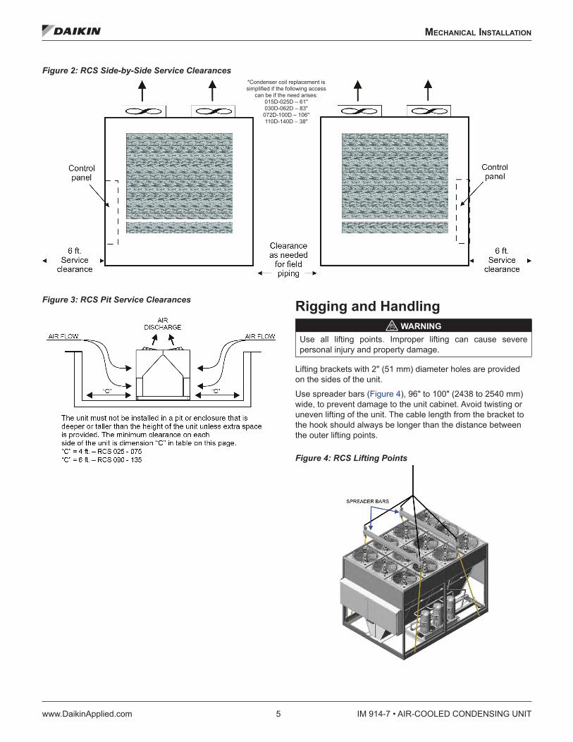
All-Aluminum Condenser Coils The condenser coils are an all-aluminum design including the connections, micro-channels, fins (an oven brazing process brazes the fins to the micro-channel flat tube), and headers (Figure 25), which eliminates the possibility of corrosion normally found between dissimilar metals of standard coils.
During the condensing process, refrigerant in the coil passes through the micro-channel flat tubes, resulting in higher efficiency heat transfer from the refrigerant to the airstream.
Figure 25: Micro-Channel Coil Cross-Section
Figure 26: Aluminum/Copper Connection
Connecting the Condenser Coil to Copper Tubing
CAUTIONPotential equipment damage. If a standard copper brazing process is performed at this joint, the process will damage the aluminum connection. If a leak is found at a copper aluminum joint, it is recommended that the entire microchannel coil module be replaced. Do not attempt to repair the copper aluminum joint on site.
Figure 26 shows the aluminum condenser coil connection to the copper tubing in the unit. Because of the low melting point of aluminum (1220°F compared to 1984°F for copper), this brazed joint is performed with a low temperature brazing process.
Micro-Channel aluminum coil cleaning recommendations
1. Use a high pressure sprayer (water only). Do not exceed 900 psig. A wide spray nozzle is best.
2. Direct spray to the coil and do not exceed a 45º angle.
3. Nozzle must be a minimum of 12ʺ from the coil face.
4. Do not directly spray the aluminum-to-copper connection joint.
5. Do not use chemical or strong detergent cleaners. If a mild detergent soap is used, the coil must be thoroughly rinsed with water. Any detergent left on the coil surfaces will promote corrosion.

MaInTenanCe
www.DaikinApplied.com 33 IM 914-7 • AIR-COOLED CONDENSING UNIT
Cleaning Option E Coated Coils WARNING
Prior to cleaning the unit, turn off and lock out the main power switch to the unit and open all access panels.
The following cleaning procedures are recommended as part of the routine maintenance activities for Option E Coated Coils. Documented routine cleaning of Option E Coated Coils is required to maintain warranty coverage.
Remove Surface Loaded Fibers Surface loaded fibers or dirt should be removed prior to water rinse to prevent further restriction of airflow. If unable to back wash the side of the coil opposite that of the coils entering air side, then surface loaded fibers or dirt should be removed with a vacuum cleaner. If a vacuum cleaner is not available, a soft non-metallic bristle brush may be used. In either case, the tool should be applied in the direction of the fins. Coil surfaces can be easily damaged (fin edges bent over) if the tool is applied across the fins. NOTE: Use of a water stream, such as a garden hose,
against a surface loaded coil will drive the fibers and dirt into the coil. This will make cleaning efforts more difficult. Surface loaded fibers must be completely removed prior to using low velocity clean water rinse.
Periodic Clean Water Rinse A monthly clean water rinse is recommended for coils that are applied in coastal or industrial environments to help to remove chlorides, dirt and debris. An elevated water temperature (not to exceed 130ºF) will reduce surface tension, increasing the ability to remove chlorides and dirt. Pressure washer PSI must not exceed 900 psig and the nozzel should remain at leat 1 foot from the coil to avoid damaging fin edges.
Routine Quarterly Cleaning of Option E Coated Coil Surfaces Quarterly cleaning is essential to extend the life of an Option E Coated Coil and is required to maintain warranty coverage. Coil cleaning shall be part of the unit’s regularly scheduled maintenance procedures. Failure to clean an Option E Coated Coil will void the warranty and may result in reduced efficiency and durability in the environment.
For routine quarterly cleaning, first clean the coil with the below approved coil cleaner (see approved products list under Recommended Coil Cleaners section, Table 12). After cleaning the coils with the approved cleaning agent, use the approved chloride remover (under the Recommended Chloride Remover section) to remove soluble salts and revitalize the unit.
Table 12: Option E Coated Coil Recommended Cleaning Agents
Cleaning Agent Reseller Part Number
Enviro-Coil Concentrate
Hydro-Balance CorpP.O. Box 730Prosper, TX 75078800-527-5166
H-EC01
Enviro-Coil Concentrate Home Depot H-EC01
Chloride Remover
Chlor*Rid Int’l, Inc.P.O. Box 908Chandler AZ 85244800-422-3217
Chlor*Rid DTS

IM 914-7 • AIR-COOLED CONDENSING UNIT 34 www.DaikinApplied.com
MaInTenanCe
Servicing Refrigerant Sensors or Switches The Daikin Condensing Unit includes the following refrigerant sensors or switches.
1. Low refrigerant pressure sensing, operating switch, automatic reset
a. Disables their associated compressors on a drop in suction pressure. Units with Fantrol, setpoint = 70 psig. Units with optional 0° low ambient, setpoint = 25 psig (low ambient).
b. Enables their associated compressors on a rise in suction pressure. Units with Fantrol, setpoint = 120 psig. Units with optional 0° low ambient, setpoint = 60 psig.
2. High refrigerant pressure, protective switch, manual reset, reset by breaking control power to the S1 control switch.
a. All R-410A high pressure switches disable their associated compressors on a rise in discharge pressure to 650 psig.
b. The switches have a differential of 150 psig.
The low pressure and optional 0° low ambient sensors/ switches sense refrigerant pressure through Shrader fittings that contain cores. The cores are stop valves that do not allow refrigerant to flow through the Shrader unless the device is in place. Therefore the low pressure and SpeedTrol sensors/ switches can be replaced without reclaiming the refrigerant.
The Shrader that serves the high pressure switch does not contain a core in order to maximize the functionality of the safety. Therefore it cannot be replaced unless the refrigerant has already been reclaimed.
Control Panel Components The following motor control protection is provided.
Table 13: RoofPak Individual Motor Control and Protection
Motor Type Short Circuit Overload On-OffCompressor < 100
Amps MMP Internal Contactor
Compressor > 100 Amps CB Internal Contactor
Condenser Fans MMP VFD ContactorEAF, One Fan CB* OL ContactorEAF, 2-3 Fans CB* Contactor
SAF & RAF with VFD No Bypass In Bypass
CB*CB
VFDOL
ContactorContactor
MMP = manual motor protectoInternal = vendor motor protectCB = circuit breaker [* FB with MD4OL = over load relay
Manual Motor Protector (MMP)The manual motor protector (MMP) provides coordinated branch circuit, short circuit protection, a disconnecting means,a motor controller, and coordinated motor overload protection. A short circuit indicator with manual reset is mounted alongside of each MMP as a means to differentiate between a short circuit and overload trip conditions.
The MMP trip points are factory set. Do not change unless the motor ampacity changes or the MMP is replaced with a new device with incorrect setpoint adjustment. Any other non-authorized trip point or setpoint adjustment voids all or portions of the unit’s warranty. Authorized setpoint adjustments accomplished as follows
1. For motors with a 1.15 service factor, rotate the arrow onthe dial to correspond to the motor FLA.
2. For motors with a 1.0 service factor, multiply the motor FLA by 0.9; then rotate the arrow on the dial to correspond to that value.
To reset a tripped MMP, clear the trip by rotating the knob counterclockwise to the OFF (O) position; then rotate knob clockwise to the ON (I) position. See Figure 27.
WARNINGIf an overload or a fault current interruption occurs, check circuits to determine the cause of the interruption. If a fault condition exits, examine the controller. If damaged, replace it to reduce the risk of fire or electrical shock.

MaInTenanCe
www.DaikinApplied.com 35 IM 914-7 • AIR-COOLED CONDENSING UNIT
Other MMP Features: • Three-position rotary operator: OFF (O)-TRIP-ON (I)
(Figure 27). • Lockout—tagoutable rotary operator: turn the rotary
operator to OFF (O), slide out the extension arm, and insert a lockout pin.
• Ambient compensated –20°C to +40°C. • Single-phase sensitivity: if one phase exceeds setpoint,
all three phases open. • Trip test: insert a 9/64” screw driver in the test slot (Figure
27 to simulate a trip.
Figure 27: Manual Motor Protector
Thermal Overload Relay Designed to provide current-dependent protection for loads with normal starting against impermissibility high temperature rises due to overload, phase asymmetry or phase failure. Increase in motor current beyond set point as a result to overload or phase failure will trip the overload and disconnect the motor.
The Relay trip points are factory set. Do not change unless the motor ampacity changes or the Relay is replaced with a new device with incorrect set point adjustment. Any other non-authorized trip points or set points adjustment voids all or portions of the unit’s warranty. Authorized set point adjustment is accomplishment as follows:
1. For motors with 1.15 service factor, rotate the arrow on the dial to correspond to the motor FLA (See Figure 28).
2. For motors with a 1.0 service factor, multiply the motor FLA with 0.9; then rotate the arrow on the dial to correspond to that value.
To reset a tripped Relay, push the blue RESET button. To disconnect, push the Red stop Button (See Figure 28).
Other relay features: • Three connection systems options, Screw type, spring
loaded and ring cable lug connection. • Switch position indicator to indicate a trip and TEST
function for wiring. • Large rotary button to adjust current to Motor RLA. • Selector switch for manual/and automatic RESET.
Figure 28: Overload Relay

IM 914-7 • AIR-COOLED CONDENSING UNIT 36 www.DaikinApplied.com
MaInTenanCe
Circuit Breaker Circuit breakers are installed upstream of all VFDs to provide short circuit protection. These breakers are not adjustable.
To reset a tripped circuit breaker: Clear the trip by rotating the lever down to the OFF position (see Figure 30). Then rotate lever up to the ON position (see Figure 30).
Breakers, like MMPs, have three distinct modes of operation which are clearly indicated by the handle position. The positions are ON (usually up, OFF (usually down), and TRIPPED (midway). Some circuit breakers may have a push-to-test button.
1. Press the handle or rotate the lever to the OFF position.
2. Press the handle or rotate the lever the opposite direction to the ON position.
Reset After Tripping Information
CAUTIONIf a breaker is tripped, the handle/lever will be halfway between the OFF and ON positions. To reset a tripped circuit breaker:
WARNINGIf a circuit breaker has tripped due to an overload or a fault current (short circuit), prior to resetting, the connected wiring circuits must be checked to determine the cause of the interruption.
Figure 29: Circuit Breaker
Field Wiring Terminals All field wiring terminals are spring clamp type, which offer several advantages over traditional screw-type terminals:
• Spring connections do not require torquing • Spring connections resist failure due to vibration • Easily identifiable terminal markers • Combination spring release and square test ports Wire
connections require inserting (“1” in Figure 30 a stripped wire a round port and clamping the stripped wire by inserting a flat-bladed screw driver in the adjacent square port (“2” in Figure 30).
Figure 30: Terminal Connectors

MaInTenanCe
www.DaikinApplied.com 37 IM 914-7 • AIR-COOLED CONDENSING UNIT
Phase Voltage Monitor (PVM) The phase voltage monitor (Figure 31) is designed to protect three-phase loads from damaging power conditions. A microprocessor-based voltage and phase sensing circuit constantly monitors the three-phase voltages to detect harmful power line conditions. When a harmful condition is detected, its output relay is deactivated after a specified trip delay (Trip Delay). The output relay reactivates after power line conditions return to an acceptable level for a specified amount of time (Restart Delay). The trip and restart delays prevent nuisance tripping due to rapidly fluctuating power line conditions.
There are two LEDs on the face of the PVM (“1” in Figure 31) to indicate the following:
Table 14: LED Indication
Status LED IndicatorNormal operation, no faults, relay energized Green LED: steady ON
Loss of input phase (relay de-energized) Red LED: flash twice, OFF, flash twice, OFF, etc.
Voltage unbalance (relay de-energized) Red LED: flash twice, OFF, flash twice, OFF, etc.
High or low voltage (relay de-energized) Red LED: steady ON
Phase reversal (relay de-energized) Red LED: pulse ON, OFF, ON, OFF, etc.
Restart delay (fault cleared, PVM pending restart, relay de-energized)
Green LED: pulse ON, OFF, ON, OFF, etc.
Other features: • Standard 2% to 8% variable voltage unbalance (“3” in
Figure 31). • Standard 1 to 500 second variable restart delay (“2” in
Figure 31). • Standard 1 to 30 second trip delay (“4” in Figure
31) (except loss of phase, which trips at 1 second nonadjustable).
Figure 31: Phase Voltage Monitor
Through-the-door Disconnect DANGER
Hazardous voltage. May cause severe injury or death. Disconnect electric powe before servicing equipment. More than one disconnect may be required to de-energize the unit.
CAUTIONMolded case switches do not provide over-current protection. This device may automatically open the circuit at levels above the ampere rating of the switch.
The optional “through-the-door” disconnect is a molded case switch with similar features of the circuit breaker. The “through-the-door” feature provides a safety interlock that disables power when the control panel door is opened. Opening the through-the-door disconnect without performing a proper machine shut-down is not recommended except in emergencies.
The through-the-door disconnect also provides for locking out power to the unit. To lock out power to the unit, rotate the handle to the “Reset/Lock” position and insert a padlock or locking device through the base of the handle. Do not lockout the handle with the Interlock in bypass mode.
Figure 32: Through-the-door Handle Disconnect

IM 914-7 • AIR-COOLED CONDENSING UNIT 38 www.DaikinApplied.com
MaInTenanCe
Controlled Shut-down/Interlock Bypass To access the control panel while power is active, for troubleshooting or performing a controlled shut-down, the through-the-door disconnect’s interlock feature can be bypassed. The control panel door can be opened without disabling power to the control panel.
1. Insert a flat blade screwdriver into the slotted “release” located on the end of the disconnect faceplate (Figure 33).
2. Turn the release counter-clockwise and pull the door open.
3. To shut down an operating unit (no emergency condition present):
a. Use the pump down switch to turn off the unit.
b. The controls will then shut the liquid line solenoids, pump the refrigerant into the condenser, and turn off the compressors.
Figure 33: Interlock Bypass
Pressure Sensors The MicroTech III controller uses 0 to 5ʺ W.C. static pressure transducers for measuring duct static pressure. As the duct static pressure varies from 0-5ʺ W.C., the transducer output will vary from 4-20mA. The transducer output signal is 420mA however the signal entering the VFD is converted to a DC signal via a 500 Ohm resistor across the output signal at the transducer.
If building static pressure control is provided, a -0.25ʺ W.C. to 0.25ʺ W.C. static pressure transducer is used. As the building static pressure varies from -0.25ʺ W.C. to 0.25ʺ W.C., the transducer output will vary from 4-20mA. The transducer output signal is 4-20mA however the signal entering the VFD is converted to a DC signal via a 500 Ohm resistor across the output signal at the transducer.
Troubleshooting Pressure Transducers Use the following procedure to troubleshoot a suspect sensor:
If the duct static pressure always reads 0ʺ WC on the unit keypad/display and the VFD speed is continuously ramping to 100%, check the following:
If the unit has two duct static pressure sensors (SPS1 and SPS2), verify that they both function properly per the following procedure. Also check for faulty wiring connections at the VFD analog inputs.
The controller displays and controls to the lower of the two readings. If a sensor is defective and inputs 0 volts to the VFD, the static pressure reading on the keypad/display reads 0 and the controller attempts to increase the 0 value to set point by ramping the VFD up.
If a second sensor (SPS2) is not installed or the pressure tubing to it is not connected, make sure the 2nd DSP Sensor= parameter in the Unit Configuration menu of the keypad/ display is set to “No” so that the controller ignores the second static pressure analog input.
If a second sensor (SPS2) is installed, make sure the 2nd DSP Sensor= parameter in the Unit Configuration menu of the keypad/display is set to “Yes.”
Check the 24 V (dc) power supply to the sensor, verify that there is 24 V (dc) between the suspect transducer “+” and “-” terminals.
Using an accurate manometer or gauge, measure the same pressure that the suspect transducer is sensing. To do this, tap into the transducer high and low pressure tubing or locate the measurement device taps next to the transducer taps.
If the suspect sensor is measuring duct static pressure, verify that the high and low pressure taps are properly installed. An improper pressure tap installation can cause severe fluctuations in the sensed pressure. Refer to the model-specific installation manual for pressure tap installation guidelines.
Measure the DC voltage output from the transducer across the sensor “S” and “-” terminals.
If the measured voltage and pressure do not match, there may be a wiring problem, the factory 500 ohm resistor across “S” and “-” or the transducer may be defective. Check the transducer input circuit wiring and connections for defects. If the measured voltage and pressure match, the VFD parameters and/or ModBus communication between the controller and the VFD will need to be verified.
Remove powers from the controller by opening system switch S1. If available, swap a similar good transducer with the suspect transducer or try installing a new transducer. Restore power by closing S1 and verify whether the suspect transducer is defective.

servICe and WarranTy proCedure
www.DaikinApplied.com 39 IM 914-7 • AIR-COOLED CONDENSING UNIT
servICe and WarranTy proCedure
Replacement Parts When writing to Daikin for service or replacement parts, provide the model number, serial number, and unit part number of the unit as stamped on the serial plate attached to the unit. For questions regarding wiring diagrams, it will be necessary to provide the number on the specific diagram. If replacement parts are required, include the date of unit installation, the date of failure, an explanation of the malfunction, and a description of the replacement parts required.
Scroll Compressor Daikin Condensing Units use the following Copeland Scroll Compressors.
1. Single compressors, one per refrigerant circuit.
2. Tandem compressors, basically two compressors specifically manufactured by Copeland into a single assembly.
3. Trio compressors, basically three single compressors factory piped in parallel with equalization lines.
All Daikin Condensing Units include a first-year parts only warranty. The warranty period extends 12 months from startup or 18 months from date of shipment, whichever comes first. Labor to install these parts is not included with this warranty. Compressors are considered a part and are included in this standard warranty.
Scroll service replacement compressors for Daikin Condensing Units can be obtained from the following two sources:
• Daikin Service Parts maintains a stock of replacement compressors.
• Copeland Refrigeration has stocking wholesalers throughout the U.S. who maintain a limited stock of replacement scroll compressors. The stock of single compressors is much better than the stock of tandem (or tandem/trio ready) single compressors. Trios are almost never in wholesaler stock and are not recommended for use on Daikin Condensing Units due to piping interference. Copeland does offer quick ship options though their wholesalers.
Both sources can be used at the customer’s discretion.
In Warranty Limitation 1. RCS 050D to 068D—Only the failed portion of the
tandem may need replacement.
2. RCS 070D to 140D—Only the failed portion of the trio may need replacement.
Always remember that only a “tandem or trio ready” compressor with oil equalizer lines can be used to replace a portion of the tandem or trio.
All Compressors The decision to replace the failed portion of the tandem or trio, as opposed to replacing the entire tandem or trio, must be decided based on the following.
1. In warranty: Warranty only covers replacement of the failed portion of the tandem or trio. Either source may be used.
2. Out of warranty: The customer decides whether to replace the entire tandem/trio or just a portion and either source may be used.
When replacing an “in warranty” compressor through a Copeland Wholesaler, take the failed compressor to the wholesaler for an over-the-counter or an advanced replacement exchange. Credit is issued by Copeland on the returned motor compressor upon receipt and factory inspection of the inoperative motor compressor. In this transaction, be certain that the motor compressor is definitely defective. If a motor compressor is received from the field that tests satisfactorily, a service charge plus a transportation charge will be charged against its original credit value.
If there was a delay in the startup of the equipment and the first-year warranty (Copeland) has expired on the compressor, within the 18-month-from-shipment warranty, order the replacement compressor through the Daikin Parts Department (Minneapolis).
1. Contact the Daikin Parts Department for compressor availability.
2. Send a completed parts order form to the Daikin Parts Department.
3. The Parts Department processes the order and the compressors are shipped from our Dayton, OH warehouse via ground transportation. If next-day air is required, indicate this on the parts order form and a freight charge will be billed to your account. Air freight costs are not covered under the Daikin warranty.
4. After the failed compressor is replaced, return it to Daikin with a Return Goods Tag attached (received by mail). It must be attached to the compressor. The Return Goods Tag has instructions on where to send the compressor. If the compressor is not returned, you will be billed for the replacement compressor.
IM 914-7 • AIR-COOLED CONDENSING UNIT 40 www.DaikinApplied.com
servICe and WarranTy proCedure
On Daikin equipment that includes the extended 2nd -5th year compressor warranty option, the replacement compressor must be ordered through the Daikin Parts Department (Minneapolis).
1. Contact the Daikin Parts Department for compressor availability.
2. Send the Daikin Parts Department a completed parts order form.
3. The Parts Department will process the order and the compressors will be shipped from our Dayton, OH warehouse via ground transportation. If next-day air is required, you will need to indicate this on the parts order form and a freight charge will be billed to your account. Air freight costs are not covered under the Daikin warranty.
4. After the failed compressor has been replaced, it must be returned to with a Return Goods Tag attached. You will receive the tag in the mail and it must be attached to the compressor. The Return Goods Tag will have instructions on where to send the compressor. If the compressor is not returned, you will be billed for the replacement compressor.
5. Consideration may be given at this time to a compressor teardown analysis depending on the history of failures.
In-Warranty Return Material Procedure Material other than compressors may not be returned except by permission of authorized factory service personnel of Daikin at Minneapolis, Minnesota.
A “return goods” tag will be sent to be included with the returned material. Enter the information as called for on the tag in order to expedite handling at out factories and issuance of credits. All parts shall be returned to the factory designated on the return goods tag, transportation charges prepaid.
The return of the part does not constitute an order for replacement. A purchase order for the replacement part must be entered through your nearest Daikin representative. The order should include the component’s part number and description and the model and serial numbers of the unit involved.
If it is determined that the failure of the returned part is due to faulty material or workmanship within the standard warranty period, credit will be issued on the customer’s purchase order.

lIMITed produCT WarranTy
www.DaikinApplied.com 41 IM 914-7 • AIR-COOLED CONDENSING UNIT
lIMITed produCT WarranTy
North AmericaDaikin (“Company”) warrants to contractor, purchaser and any owner of the product (collectively “Owner”) that Company, at its option, will repair or replace defective parts in the event any product manufactured by Company, including products sold under the brand names McQuay Air Conditioning, AAF Air Conditioning, AAF HermanNelson and McQuay Service, and used in the United States or Canada, proves defective in material or workmanship within twelve (12) months from initial startup or eighteen (18) months from the date shipped by Company, whichever occurs first. Authorized replaced parts are warranted for the duration of the original warranty. All shipments of such parts will be made FOB factory, freight prepaid and allowed. Company reserves the right to select carrier and method of shipment.
In addition, labor to repair or replace warranty parts is provided during Company normal working hours on products with rotary screw compressors, centrifugal compressors and on absorption chillers. Warranty labor is not provided for any other products.
Company’s liability to Owner under this warranty shall not exceed the lesser of the cost of correcting defects in the products sold or the original purchase price of the products.
PRODUCT STARTUP ON ABSORPTION, CENTRIFUGAL AND SCREW COMPRESSOR PRODUCTS IS MANDATORY and must be performed by Daikin Service or a Company authorized service representative.
It is Owner’s responsibility to complete and return the Registration and Startup Forms accompanying the product to Company within ten (10) days of original startup. If this is not done, the ship date and the startup date will be deemed the same for warranty period determination, and this warranty shall expire twelve (12) months from that date.
Exceptions 1. If free warranty labor is available as set forth above, such
free labor does not include diagnostic visits, inspections, travel time and related expenses, or unusual access time or costs required by product location.
2. Refrigerants, fluids, oils and expendable items such as filters are not covered by this warranty.
3. This warranty shall not apply to products or parts which (a) have been opened, disassembled, repaired, or altered by anyone other than Company or its authorized service representative; or (b) have been subjected to misuse, negligence, accidents, damage, or abnormal use or service; or (c) have been operated, installed, or startup has been provided in a manner contrary to Company’s printed instructions, or (d) were manufactured or furnished by others and which are not an integral part of a product manufactured by Company; or (e) have not been fully paid for by Owner.
Assistance To obtain assistance or information regarding this warranty, please contact your local sales representative or Daikin Service office.
Sole Remedy/Disclaimer THIS WARRANTY CONSTITUTES THE OWNER’S SOLE REMEDY. IT IS GIVEN IN LIEU OF ALL OTHER WARRANTIES. THERE IS NO IMPLIED WARRANTY OF MERCHANTABILITY OR FITNESS FOR A PARTICULAR PURPOSE. IN NO EVENT AND UNDER NO CIRCUMSTANCE SHALL COMPANY BE LIABLE FOR INCIDENTAL, INDIRECT, SPECIAL, CONTINGENT OR CONSEQUENTIAL DAMAGES, WHETHER THE THEORY BE BREACH OF THIS OR ANY OTHER WARRANTY, NEGLIGENCE OR STRICT LIABILITY IN TORT.
No person (including any agent, sales representative, dealer or distributor) has the authority to expand the Company’s obligation beyond the terms of this express warranty or to state that the performance of the product is other than that published by Company.
For additional consideration, Company will provide an extended warranty(ies) on certain products or components thereof. The terms of the extended warranty(ies) are shown on a separate extended warranty statement.

IM 914-7 • AIR-COOLED CONDENSING UNIT 42 www.DaikinApplied.com
rCs CondensIng equIpMenT WarranTy regIsTraTIon forM
rCs CondensIng equIpMenT WarranTy regIsTraTIon forM
13F-4155 (03/15) ©2015 Daikin Applied • (800) 432-1342 • www.DaikinApplied.com
RCS CondensingEquipment Warranty Registration FormTo comply with the terms of Daikin Applied Warranty, complete and return this form within 10 days to the Warranty Department of Daikin Applied.
Check, test, and start procedure for Rooftop roof mounted air conditioners with or without heat recovery and roof mounted air handlers.
GENERAL INFORMATION
Job Name: ____________________________________________________________ GOI No.: _______________________________
Installation address: _____________________________________________________________________________________________
City: _________________________________________________________________ State: _________________________________
Purchasing contractor: ___________________________________________________________________________________________
City: _________________________________________________________________ State: _________________________________
Name of person doing start-up: ____________________________________________________________________________________
Company name: ________________________________________________________________________________________________
Address: ______________________________________________________________________________________________________
City/State/Zip: __________________________________________________________________________________________________
UNIT INFORMATION
Unit model number: ____________________________________________________ Unit serial number: ______________________
Compressor 1 model number: ____________________________________________ Serial number: __________________________
Compressor 2 model number: ____________________________________________ Serial number: __________________________
Compressor 3 model number: ____________________________________________ Serial number: __________________________
Compressor 4 model number: ____________________________________________ Serial number: __________________________
Compressor 5 model number: ____________________________________________ Serial number: __________________________
Compressor 6 model number: ____________________________________________ Serial number: __________________________

rCs CondensIng equIpMenT WarranTy regIsTraTIon forM
www.DaikinApplied.com 43 IM 914-7 • AIR-COOLED CONDENSING UNIT
RCS Equipment Warranty Registration Form (continued)
13F-4155 (03/15) 2
Select Yes or No. If not applicable to the type of unit, select N/A.
I. INITIAL CHECK A. Is any shipping damage visible? . . . . . . . . . . . . . . . . . . . . . . . . . . . . . . . . . . . . . . . . Yes No N/A
B. Tightened all setscrews?. . . . . . . . . . . . . . . . . . . . . . . . . . . . . . . . . . . . . . . . . . . . Yes No N/A
C. Have the shipping spacers been removed from the compressor springs and have the neoprene spacers been installed on each compressor mounting bolt? . . . . . . . . . . . . . . . . . . . . . . . . . Yes No N/A
D. Electrical service corresponds to unit nameplate?. . . . . . . . . . . . . . . . . . . . . . . . . . . . . . . Yes No N/A
Volts _____________ Hertz _____________ Phase _____________
E. Is the main disconnect adequately fused and are fuses installed? . . . . . . . . . . . . . . . . . . . . . . Yes No N/A
F. Are crankcase heaters operating, and have they been operating 24 hours prior to start-up? . . . . . . . . . Yes No N/A
G. Are all electrical power connections tight? (Check compressor electrical box.) . . . . . . . . . . . . . . . . Yes No N/A
H. Has the field piping been piped per ASHRAE recommendations?. . . . . . . . . . . . . . . . . . . . . . . Yes No N/A
II. START-UP COMPRESSOR OPERATION A. Has each circuit been field leak tested?
Circuit #1. . . . . . . . . . . . . . . . . . . . . . . . . . . . . . . . . . . . . . . . . . . . . . . . . . . . Yes No N/ACircuit #2. . . . . . . . . . . . . . . . . . . . . . . . . . . . . . . . . . . . . . . . . . . . . . . . . . . . Yes No N/A
B. Refrigerant charge per circuit: . . . . . . . . . . . . . . . . . . . . . . . . . . . . . . . Circuit 1 ________ Circuit 2 ________
C. Are compressors rotating in the right direction?. . . . . . . . . . . . . . . . . . . . . . . . . . . . . . . . Yes No N/A
D. Do condenser fans rotate in the right direction? . . . . . . . . . . . . . . . . . . . . . . . . . . . . . . . . Yes No N/A
E. Ambient temperature. . . . . . . . . . . . . . . . . . . . . . . . . . . . . . . . . . . . . . . . . . . . . . . . . _____________°F
F. Compressor lockout timers function? . . . . . . . . . . . . . . . . . . . . . . . . . . . . . . . . . . . . . Yes No N/A
G. FanTrol functions: . . . . . . . . . . . . . . . . . . . . . TC12 _____________ TC13 _____________ TC14 _____________
H. Does unit start up and perform per sequence of operation? . . . . . . . . . . . . . . . . . . . . . . . . . Yes No N/A
III. PERFORMANCE DATA A. Compressor voltage across each phase: . . . . . . . L1–2_____________ V L2–3 _____________ V L1–3 _____________ V
B. Compressor amperage of fully loaded compressor . Compressor #1 — Phase 1________ Phase 2 ________ Phase 3 _______
Compressor #2 — Phase 1________ Phase 2 ________ Phase 3 _______
Compressor #3 — Phase 1________ Phase 2 ________ Phase 3 _______
Compressor #4 — Phase 1________ Phase 2 ________ Phase 3 _______
Compressor #5 — Phase 1________ Phase 2 ________ Phase 3 _______
Compressor #6 — Phase 1________ Phase 2 ________ Phase 3 _______
C. Low pressure cut-out: . . . . . . . . . . . . . . . . . . . . . . . . . . . . . Circuit 1 __________ psig Circuit 2 __________ psig
Low pressure cut-in: . . . . . . . . . . . . . . . . . . . . . . . . . . . . . .Circuit 1 __________ psig Circuit 2 __________ psig
D. High pressure cut-out: . . . . . . . . . . . . . . . . . . . . . . . . . . . . .Circuit 1 __________ psig Circuit 2 __________ psig
E. Discharge pressure, one compressor: . . . . . . . . . . . . . . . . . . . . . Circuit 1 __________ psig Circuit 2 __________ psig
Discharge pressure, fully loaded, 2–3 compressors: . . . . . . . . . . . . . Circuit 1 __________ psig Circuit 2 __________ psig

IM 914-7 • AIR-COOLED CONDENSING UNIT 44 www.DaikinApplied.com
rCs CondensIng equIpMenT WarranTy regIsTraTIon forM
RCS Equipment Warranty Registration Form (continued)
13F-4155 (03/15) 3
Select Yes or No. If not applicable to the type of unit, select N/A.
F. Suction pressure, one compressor: . . . . . . . . . . . . . . . . . . . . . .Circuit 1 __________ psig Circuit 2 __________ psig
Suction pressure, fully loaded, 2–3 compressors: . . . . . . . . . . . . . . .Circuit 1 __________ psig Circuit 2 __________ psig
Liquid press, fully loaded, 2–3 compressors (at liquid line shutoff valve): . . . Circuit 1 __________ psig Circuit 2 __________ psig
Liquid temperature, fully loaded, 2–3 compressors: . . . . . . . . . . . . . .Circuit 1 __________ psig Circuit 2 __________ psig
Circuit 1 Circuit 2
G. Suction line temperature: . . . . . . . . . . . . . . . . . . . . . . . . . . . . . . . . . . . . ____________ °F ____________°F
H. Superheat: . . . . . . . . . . . . . . . . . . . . . . . . . . . . . . . . . . . . . . . . . . . . ____________ °F ____________°F
I. Subcooling:. . . . . . . . . . . . . . . . . . . . . . . . . . . . . . . . . . . . . . . . . . . . ____________ °F ____________°F
J. Is the liquid in the line sightglass clear and dry?. . . . . . . . . . . . . . . . . . . . . . . . . . . . . . . . Yes No N/A
K. Does the hot gas bypass valve function properly?. . . . . . . . . . . . . . . . . . . . . . . . . . . . . . . Yes No N/A
L. At what suction pressure does the hot gas bypass valve open?. . . . . . . . Circuit 1 __________ psig Circuit 2 __________ psig
M. Record discharge air temperature at discharge of unit: . . . . . . . . . . . . . . . . . . . . . . . . . . . . . . . . ___________ °F
N. Are all control lines secure to prevent excessive vibration and wear?. . . . . . . . . . . . . . . . . . . . . Yes No N/A
O. Are all gauges shut off and valve caps and packings tight after start-up? . . . . . . . . . . . . . . . . . . . Yes No N/A
Thank you for completing this form. Please sign and date below.
Signature _____________________________________________________________ Startup date: ___________________________
Return completed form by mail to: Daikin Warranty Department, 13600 Industrial Park Boulevard, Minneapolis, MN 55441
or by email to: [email protected] Please fill out the Daikin Applied “Quality Assurance Survey Report” and list any additional comments that could affect the operation of this unit; e.g., shipping damage, failed components, adverse installation applications, etc. If additional comment space is needed, write the comment(s) on a separate sheet, attach it to the Survey Report and return it to the Warranty Department of Daikin Applied with the completed Equipment Warranty Registration form.

IM 914-7 • AIR-COOLED CONDENSING UNIT 45 www.DaikinApplied.com
qualITy assuranCe survey reporT
qualITy assuranCe survey reporT
Quality Assurance Survey Report
To whom it may concern:Please review the items below upon receiving and installing our product. Select N/A on any item that does not apply to the product.
Job Name: _____________________________________________________________________ Daikin Applied G.O. No. ______________
Installation address: ____________________________________________________________________________________________________
City: ___________________________________________________________________________ State: _______________________________
Purchasing contractor: __________________________________________________________________________________________________
City: ___________________________________________________________________________ State: _______________________________
Name of person doing start-up (print): ___________________________________________________________________________________
Company name: ______________________________________________________________________________________
Address: ____________________________________________________________________________________________
City/State/Zip: _______________________________________________________________________________________
Unit model number: ____________________________________________________ Unit serial number: __________________________
1. Is there any shipping damage visible? . . . . . . . . . . . . . . . . . . . . . . . . . . . . . . . . . . . . . . . . . . . . . . . . . . . . . . . . . . . . . . . . . . Yes No N/A
Location on unit ____________________________________________________________________________________
2. How would you rate the overall appearance of the product; i.e., paint, fi n damage, etc.? Excellent Good Fair Poor
3. Did all sections of the unit fi t together properly? . . . . . . . . . . . . . . . . . . . . . . . . . . . . . . . . . . . . . . . . . . . . . . . . . . . . . . . . . . Yes No N/A4. Did the cabinet have any air leakage? . . . . . . . . . . . . . . . . . . . . . . . . . . . . . . . . . . . . . . . . . . . . . . . . . . . . . . . . . . . . . . . . . . Yes No N/A
Location on unit ___________________________________________________________________________________
5. Were there any refrigerant leaks? . . . . . . . . . . . . . . . . . . . . . . . . . . . . . . . . . . . . . . . . . . . . . . . . . . . . . . . . . . . . . . . . . . . . . Yes No N/A
From where did it occur? . . . . . . . . . . . . . . . . . . . . . . . . . . . . . . . . . . . Shipping Workmanship Design
6. Does the refrigerant piping have excessive vibration? . . . . . . . . . . . . . . . . . . . . . . . . . . . . . . . . . . . . . . . . . . . . . . . . . . . . . . Yes No N/A
Location on unit ___________________________________________________________________________________
7. Did all of the electrical controls function at start-up? . . . . . . . . . . . . . . . . . . . . . . . . . . . . . . . . . . . . . . . . . . . . . . . . . . . . . . . Yes No N/A
Comments _______________________________________________________________________________________
8. Did the labeling and schematics provide adequate information? . . . . . . . . . . . . . . . . . . . . . . . . . . . . . . . . . . . . . . . . . . . . . . Yes No N/A
9. How would you rate the serviceability of the product? Excellent Good Fair Poor
10. How would you rate the overall quality of the product? Excellent Good Fair Poor
11. How does the quality of Daikin Applied products rank in relation to competitive products? Excellent Good Fair Poor
Comments _______________________________________________________________________________________
Please list any additional comments which could affect the operation of this unit; i.e., shipping damage, failed components, adverse installation applications, etc. If additional comment space is needed, write the comment(s) on a separate sheet, attach the sheet to this completed Quality Assurance Survey Report, and return it to the Warranty Department with the completed preceding “Equipment Warranty Registration Form”.
13-4160 (05/14) ©2014 Daikin Applied • (800) 432-1342 • www.DaikinApplied.com
IM 914-7 (11/15) ©2015 Daikin Applied | (800) 432–1342 | www.DaikinApplied.com
Daikin Applied Training and DevelopmentNow that you have made an investment in modern, efficient Daikin equipment, its care should be a high priority. For training information on all Daikin HVAC products, please visit us at www.DaikinApplied.com and click on Training, or call 540-248-9646 and ask for the Training Department.
Warranty
All Daikin equipment is sold pursuant to its standard terms and conditions of sale, including Limited Product Warranty. Consult your local Daikin Applied representative for warranty details. To find your local Daikin Applied representative, go to www.DaikinApplied.com.
Aftermarket Services
To find your local parts office, visit www.DaikinApplied.com or call 800-37PARTS (800-377-2787). To find your local service office, visit www.DaikinApplied.com or call 800-432-1342.
This document contains the most current product information as of this printing. For the most up-to-date product information, please go to www.DaikinApplied.com.
Products manufactured in an ISO Certified Facility.