Air Cooled Split System Condensing Unit Group: Applied...
40
© 2008 Daikin Applied Model RCS 025C to 135C R-22/R-407C Refrigerant Installation and Maintenance Manual IM 903 Air Cooled Split System Condensing Unit for Rooftop Systems and Air Handlers Group: Applied Systems Part Number: IM 903 Date: January 2008 US
Transcript of Air Cooled Split System Condensing Unit Group: Applied...

© 2008 Daikin Applied
Model RCS 025C to 135C
R-22/R-407C Refrigerant
Installation and Maintenance Manual IM 903
Air Cooled Split System Condensing Unitfor Rooftop Systems and Air Handlers
Group: Applied Systems
Part Number: IM 903
Date: January 2008
US

Contents
Introduction . . . . . . . . . . . . . . . . . . . . . . . . . . . . . . . 3Hazard Identification Information. . . . . . . . . . . . . . 3Agency Listed . . . . . . . . . . . . . . . . . . . . . . . . . . . . 3Nomenclature . . . . . . . . . . . . . . . . . . . . . . . . . . . . 3Condenser Fan Arrangement . . . . . . . . . . . . . . . . 4Refrigeration Piping . . . . . . . . . . . . . . . . . . . . . . . . 5
Mechanical Installation . . . . . . . . . . . . . . . . . . . . . . 7Receiving Inspection . . . . . . . . . . . . . . . . . . . . . 7Unit Placement . . . . . . . . . . . . . . . . . . . . . . . . . 7Clearances. . . . . . . . . . . . . . . . . . . . . . . . . . . . . 7Restricted Air Flow. . . . . . . . . . . . . . . . . . . . . . . 9Case 1, Building/Wall on One Side of Unit . . . . 9Case 2, Open Screening Walls . . . . . . . . . . . . 10Case 3, Pit/Solid Wall Installation . . . . . . . . . . 11
Rigging and Handling . . . . . . . . . . . . . . . . . . . . . 12Refrigerant Piping . . . . . . . . . . . . . . . . . . . . . . . . 13
Pumpdown. . . . . . . . . . . . . . . . . . . . . . . . . . . . 14Holding Charge . . . . . . . . . . . . . . . . . . . . . . . . 14Leak Testing . . . . . . . . . . . . . . . . . . . . . . . . . . 15Evacuation. . . . . . . . . . . . . . . . . . . . . . . . . . . . 15Charging the System . . . . . . . . . . . . . . . . . . . . 17Refrigerant Charge . . . . . . . . . . . . . . . . . . . . . 18Subcooling. . . . . . . . . . . . . . . . . . . . . . . . . . . . 18Refrigeration Service Valves . . . . . . . . . . . . . . 18
Electrical Installation . . . . . . . . . . . . . . . . . . . . . . 19Field Power Wiring . . . . . . . . . . . . . . . . . . . . . . . 19
Wiring Diagrams . . . . . . . . . . . . . . . . . . . . . . . . . . 20Unit Options. . . . . . . . . . . . . . . . . . . . . . . . . . . . . . 24
SpeedTrol™ . . . . . . . . . . . . . . . . . . . . . . . . . . . . 24Check, Test, and Start Procedures . . . . . . . . . . . 25
Servicing Control Panel Components . . . . . . . . . 25Before Start-up . . . . . . . . . . . . . . . . . . . . . . . . . . 25Compressor Startup . . . . . . . . . . . . . . . . . . . . . . 26Scroll Compressor RotationalDirection (025C to 105C). . . . . . . . . . . . . . . . . . . 26
Expansion Valve Superheat Adjustment . . . . . 26R-407C Superheat. . . . . . . . . . . . . . . . . . . . . . 26Checking Superheat . . . . . . . . . . . . . . . . . . . . 26
Oil Pressure (115C to 135C only) . . . . . . . . . . . . 27Refrigerant Piping Checkout . . . . . . . . . . . . . . . . 27Electrical Checkout . . . . . . . . . . . . . . . . . . . . . . . 27
Operation . . . . . . . . . . . . . . . . . . . . . . . . . . . . . . . . 28Hot Gas Bypass (Optional) . . . . . . . . . . . . . . . . . 28System Adjustment . . . . . . . . . . . . . . . . . . . . . . . 28Liquid Line Sight Glass and Moisture Indicator. . 28Refrigerant Charging. . . . . . . . . . . . . . . . . . . . . . 28Thermostatic Expansion Valve . . . . . . . . . . . . . . 28Crankcase Heaters . . . . . . . . . . . . . . . . . . . . . . . 28
Maintenance . . . . . . . . . . . . . . . . . . . . . . . . . . . . . 29Servicing Control Panel Components . . . . . . . . . 29Planned Maintenance . . . . . . . . . . . . . . . . . . . . . 29Unit Storage . . . . . . . . . . . . . . . . . . . . . . . . . . . . 29
Location. . . . . . . . . . . . . . . . . . . . . . . . . . . . . . 29Preparation . . . . . . . . . . . . . . . . . . . . . . . . . . . 29Restart. . . . . . . . . . . . . . . . . . . . . . . . . . . . . . . 29
Refrigerant Charge . . . . . . . . . . . . . . . . . . . . . . . 29Servicing Refrigerant Sensors or Switches. . . . . 30Control Panel Components . . . . . . . . . . . . . . . . . 30
Manual Motor Protector (MMP). . . . . . . . . . . . 30Other MMP features:. . . . . . . . . . . . . . . . . . . . 30Disconnect . . . . . . . . . . . . . . . . . . . . . . . . . . . 31Terminals . . . . . . . . . . . . . . . . . . . . . . . . . . . . 32Phase Voltage Monitor (PVM). . . . . . . . . . . . . 32
Service and Warranty Procedure . . . . . . . . . . . . 33Replacement Parts . . . . . . . . . . . . . . . . . . . . . . . 33Scroll Compressor (025C to 105C) . . . . . . . . . . . 33Reciprocating Compressors (115C to 135C) . . . 33All Compressors . . . . . . . . . . . . . . . . . . . . . . . . . 34
In-Warranty Return Material Procedure . . . . . 34Limited Product Warranty (North America) . . . . 35
Exceptions . . . . . . . . . . . . . . . . . . . . . . . . . . . . . 35Assistance. . . . . . . . . . . . . . . . . . . . . . . . . . . . . . 35Sole Remedy/Disclaimer. . . . . . . . . . . . . . . . . . . 35
RCS Rooftop Equipment Warranty Registration Form . . . . . . . . . . . . . . . . . . . . . . . . . . . . . . . . . . . . 36Quality Assurance Survey Report. . . . . . . . . . . . 38

Introduction
IntroductionThe Condensing Unit for Applied Rooftop and Air Handler Systems• The Daikin RCS air cooled, remote condenser offers a
wide selection of nominal capacities from 25 to 135 tons.
• Units are designed for quiet and energy efficient operation meeting ASHRAE 90.1 efficiency requirements.
• Dual circuits with scroll compressors from 25 to 105 tons with multiple stages for maximum capacity control.
• Dual circuits with Copeland Discus™ compressors (from 110 to 135 tons) with multiple steps of unloading for maximum capacity control.
• The RCS unit can be matched to a Daikin Vision®, Skyline®, or Destiny® air handling unit. No need for an estimated balance point.
• Using Daikin Select Tools a complete system can be designed and selected. Capacity, electrical information, and dimensional drawings are right at your fingertips.
Hazard Identification Information
Agency Listed
Nomenclature
DANGER
Dangers indicate a hazardous situation which will result in death or serious injury if not avoided.
WARNING
Warnings indicate potentially hazardous situations, which can result in property damage, severe personal injury, or death if not avoided.
CAUTION
Cautions indicate potentially hazardous situations, which can result in personal injury or equipment damage if not avoided.
US
Rooftop Condensing System Design vintage
R C S – 025 – C
Nominal capacity (tons)025, 030, 040, 050, 060, 070, 075, 090, 105, 115, 125, 135
Daikin IM 903 3

Introduction
Condenser Fan Arrangement
Table 1 shows the condenser fan numbering conventions and locations for each unit size.
Table 1: Condenser Fan ArrangementUnit size Refrigerant circuit Arrangement Unit size Refrigerant circuit Arrangement
025C030C
1 or 2
075C080C090C 1
2
040C
1
2
105C
1
2
045C050C
1
2
115C
1
2
060C070C
1
2
125C135C
1
2
11
12
13
11 13
23
12
2221
24 14
11
21
12
22
11 12
21 22
11 12
21 22
23 13
4 Daikin IM 903

Introduction
Refrigeration Piping
The various available configurations for unit refrigeration piping are shown in the following diagrams:
Figure 1: Circuit Schematic
Figure 2: Condenser Piping, Scroll Compressors, 1 to 3 Compressors Per Circuit are Provided (025C to 105C)
Air Handler
Condenser
A - Compressor (1, 2, or 3 per circuit) †B - Discharge line †C - Condenser coil †D - Evaporator coil *E - Manual shutoff valve †F - Filter-drier (optional) •G - Liquid line solenoid valve (optional) •H - Sightglass (optional) •I - Liquid line •*†J - Suction line •*†K - Thermal expansion valve •*L - Distributor*M - Hot gas bypass and solenoid valve (optional) •*†N - Hot gas bypass lines (optional) •*†• = Field installed* = Supplied on Air Handlers† = Supplied on RCS units
Compressor #1
Compressor #3
Compressor #2
Compressor #4
1
2
3
4
Discharge linesCircuit #1Circuit #2
Liquid linesCircuit #1Circuit #2
Optionalhot gasbypasslinesCircuit #1Circuit #2 Suction
linesCircuit #1Circuit #2
Legend1 - Discharge shut-off valve—Circuit #12 - Liquid shut-off valve—Circuit #13 - Liquid shut-off valve—Circuit #24 - Discharge shut-off valve—Circuit #2
Daikin IM 903 5

Introduction
Figure 3: Condenser Piping, 4 Reciprocating Compressors (115C to 135C)
Legend1 - Discharge Line Service Valve2 - Discharge Muffler3 - High Pressure Relief Valve4 - Liquid Line Manual Shut-off Valve5 - Suction Line Service Valve
6 Daikin IM 903

Mechanical Installation
Mechanical InstallationThe installation of this equipment shall be in accordance with the regulations of authorities having jurisdiction and all applicable codes. It is the responsibility of the installer to determine and follow the applicable codes. Low head pressure may lead to poor, erratic refrigerant feed control at the thermostatic expansion valve. The units have automatic control of the condenser fans which should provide adequate head pressure control down to 50°F (10°C) provided the unit is not exposed to windy conditions. The system designer is responsible for assuring the condensing unit is not exposed to excessive wind or air recirculation.
Receiving Inspection
When the equipment is received, all items should be carefully checked against the bill of lading to be sure all crates and cartons have been received. If the unit has become dirty during shipment (winter road chemicals are of particular concern), clean it when received.
All units should be inspected carefully for damage when received. Report all shipping damage to the carrier and file a claim. In most cases, equipment ships F.O.B. factory and claims for freight damage should be filed by the consignee.
Before unloading the unit, check the unit nameplate to make sure the voltage complies with the power supply available.
Unit Placement
RCS units are for outdoor applications and can be mounted either on a roof or at ground level. For roof mounted applications, install the unit on a steel channel or I-beam frame to support the unit above the roof. For ground level applications, install the unit on a substantial base that will not settle. A one-piece concrete slab with footings extended below the frost line is recommended. Be sure the foundation is level within 1/2" (13mm) over its length and width. The foundation must be strong enough to support the units weight.
Clearances
Do not block the flow of air to and from the condenser coil. Restricting airflow or allowing air recirculation will result in a decrease in unit performance and efficiency because discharge pressures are increased. There must be no obstruction above
the unit that would deflect discharge air downward where it could be recirculated back to the inlet of the condenser coil. The condenser fans are propeller type and will not operate with ductwork.
Install the unit with enough side clearance for air entrance to the coil and for servicing. Provide service access to the compressors, electrical control panel and piping components. Do not allow debris to accumulate near the unit where it could be drawn into the condenser coil. Keep condenser coils and fan discharge free of snow or other obstructions to permit adequate airflow for proper operation.
Figure 4: RCS 025C - 030C Service Clearances
Figure 5: RCS 025C - 030C Side by Side Service Clearances
CAUTION
Sharp edges on sheet metal and fasteners can cause personal injury.This equipment must be installed, operated, and serviced only by an experienced installation company and fully trained personnel.
Daikin IM 903 7
Mechanical Installation
Figure 6: RCS 040C - 135C Service Clearances
Figure 7: RCS 040C - 135C Side by Side Service Clearances
Figure 8: RCS 025C - 135C Pit Service Clearances
8 Daikin IM 903

Mechanical Installation
Restricted Air Flow
The clearances required for design-life operation of RCS air-cooled units are described in the previous section. Occasionally, these clearances cannot be maintained due to site restrictions, such as units being too close together, or a fence or wall restricting airflow, or both.
The condenser section is configured as shown in Figure 9. This configuration allows inlet air for the condenser coil to come in from either side. The controls sequence should be such that the circuit located away from the wall is the lead circuit.
Figure 9: Coil and Fan Arrangement (RCS 040C - 135C)
The following sections discuss the most common situations of condenser air restriction and give capacity and power adjustment factors for each.
Case 1, Building/Wall on One Side of Unit
The existence of a screening wall, or the wall of a building, in close proximity to an air-cooled unit is common in both rooftop and ground level applications. Hot air recirculation on the coils adjoining the wall will increase compressor discharge pressure, decreasing capacity and increasing power consumption. Only the compressor(s) connected to these coils will be affected.
When close to a wall, place condensing unit on the north or east-side of them. Have prevailing winds blowing parallel to the unit’s long axis. The worst case is to have wind blowing hot discharge air into the wall.
Figure 10: Unit Adjacent to Wall
Figure 11: Adjustment Factors
Daikin IM 903 9
Mechanical Installation
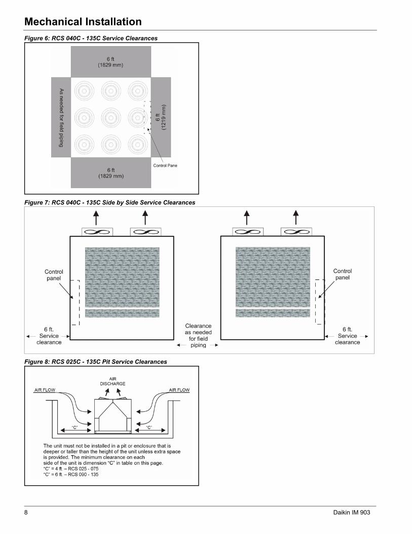
Case 2, Open Screening Walls
Decorative screening walls are often used to help conceal a unit either on grade or on a rooftop. These walls should be designed such that the combination of their open area and distance from the unit do not require performance adjustment. It is assumed that the wall height is equal to or less than the unit height when mounted on its base support. This is usually satisfactory for concealment. If the wall height is greater than the unit height, see “Case 3, Pit/Solid Wall Installation” on page 11.
The distance from the ends of the unit to the end walls must be sufficient for service, opening control panel doors, and pulling evaporator tubes, as applicable.
If each side wall is a different distance from the unit, the distances can be averaged, providing either wall is not less than 8 feet (2.4 meters) from the unit. For example, do not average 4 feet and 20 feet to equal 12 feet.
Figure 12: Opening Screening Walls
Figure 13: Wall Free Area vs. Distance
10 Daikin IM 903

Mechanical Installation
Figure 14: Pit InstallationCase 3, Pit/Solid Wall Installation
Pit installations can cause operating problems and great care should be exercised if they are to be used on an installation. Recirculation and restriction can both occur. A solid wall surrounding a unit is substantially the same as a pit and the data presented here should be used.
Steel grating is sometimes used to cover a pit to prevent accidental falls or trips into the pit. The grating material and installation design must be strong enough to prevent such accidents, yet provide abundant open area or serious recirculation problems will occur. Have any pit installation reviewed by Daikin application engineers prior to installation for air-flow characteristics. The installation design engineer must approve the work to avoid an unreasonable risk of accident and is responsible for final design criteria.
Figure 15: Pit Adjustment Factor
Daikin IM 903 11

Mechanical Installation
Rigging and Handling
Lifting brackets with 2" (51 mm) diameter holes are provided on the sides of the unit.
Use spreader bars, 96" to 100" (2438 to 2540 mm) wide, to prevent damage to the unit cabinet. Avoid twisting or uneven lifting of the unit. The cable length from the bracket to the hook should always be longer than the distance between the outer lifting points.
Figure 16: 025C to 040C Lifting Points
Figure 17: 050C to 135C Lifting Points
WARNING
Use all lifting points. Improper lifting can cause severe personal injury and property damage.
4 Lifting Points
025C - 030C: A Min. = 33.9" (861 mm)
A
A
4 Lifting Points
040C: A Min. = 85.6" (2174 mm)
12 Daikin IM 903

Mechanical Installation
Refrigerant Piping
All field piping, wiring, and procedures must be performed in accordance with ASHRAE, EPA, and industry standards. Proper refrigerant piping can make the difference between a reliable system and an inefficient, problematic system.
The primary concerns related to piping are refrigerant pressure drop, a solid liquid feed to the expansion valves, continuous oil return and properly sized refrigerant specialties.
Insulate the suction line to reduce excessive superheat build-up. Insulate the liquid line, where located in areas above ambient temperature, to prevent loss of subcooling and consequent liquid flashing.
The recommended source for refrigerant piping techniques and sizing is the Daikin AG31-011 Refrigerant Piping Design Guide.
Although conflicting piping recommendations can be found in different sources, Daikin offers the following recommendations for these controversial issues.
The use of double risers for vertical gas risers is generally not required and should be used only as a last resort to maintain the minimum refrigerant flow to carry oil up the vertical risers. Slightly downsizing the vertical riser is a preferable option to providing double risers.
Slope the refrigerant lines 1" per 10 feet of horizontal run in the direction of refrigerant flow to assist oil return.
Resist using hot gas bypass for applications when operation in ambient temperature below 40 degrees is expected. This recommendation helps to maintain adequate condensing pressures and liquid refrigerant at the expansion valve when condenser capacities are at their maximum.
Pressure drops in the refrigerant lines should be maintained at or below the ASHRAE recommendations and line lengths should be made as short as possible. Exceeding these recommendations will decrease performance and could impact reliability.
Small traps should be provided at the base of each major vertical gas riser to assist in the collection of oil. If vertical risers exceed more than 25 feet, install a small trap at the midpoint and at a maximum of 20 foot intervals.
Use caution in sizing the liquid line in applications where the evaporator is above the outdoor section. The weight of the liquid refrigerant in the vertical column will decrease the pressure at the top of the riser (approximately 0.5 psi per foot
of vertical rise) allowing some of the refrigerant to flash to a gas. Adequate refrigerant subcooling is needed at the outdoor section to prevent large volumes of refrigerant gas at the expansion valve.
The piping systems should always extend above the highest component in the refrigeration system before dropping down to make the final refrigerant connections to components. This practice will hinder the draining of condensed refrigerant to the lower component when normal shutdown procedures do not occur (such as a power failure).
Note: Do not run refrigerant lines underground.
Figure 18: 025C to 030C Refrigerant Piping Connections
Figure 19: 040C Refrigerant Piping Connections
� �
� � �
� � �
� �
� �
� �
� �
� � �
� � �
� �
� �
� �
Daikin IM 903 13

Mechanical Installation
Figure 20: 045C to 135C Refrigerant Piping Connections
Pumpdown
The pumpdown capacity of RCS units is given in the Table 4 on page 16. Care should be exercised to include all equipment and lines when calculating the system charge relative to the unit’s pumpdown capacity.
Holding Charge
The RCS unit ships with a nitrogen holding charge. At the time the unit is received, a visual inspection of the unit piping should be made to be sure no breakage occurred or that the fittings did not loosen during shipping. A pressure test on the RCS units should indicate a positive pressure in the unit. If no pressure is evident, the unit must be leak tested and the leak
repaired. Note and report this to the Daikin sales representative and freight carrier (if the loss is due to shipping damage).
Vent to atmosphere by opening gauge ports at the compressors and liquid line shutoff valves. Make sure manual valves are not back seated to shut off the gauge ports.
Table 2: Connection Sizes and Locations, Figure 18 and Figure 19
Component circuit
Connection sizes
Connection locations
025C030C to
040C
RCS 025 to 030 RCS 040
X (in.) Y (in.) X (in.) Y (in.)
S1 Suction line Ckt.1 1 5/8 1 5/8 67.60 6.25 59.50 19.30S2 Suction line Ckt.2 1 3/8 1 5/8 28.00 6.25 34.60 19.30L1 Liquid line Ckt.1 7/8 7/8 75.00 6.25 70.50 25.00L2 Liquid line Ckt.2 7/8 7/8 21.00 6.25 23.50 25.00
HG1 HGBP line Ckt.1 7/8 7/8 60.80 6.25 64.60 6.60HG2 HGBP line Ckt.2 7/8 7/8 35.50 6.25 29.50 6.00
Table 3: Connection Sizes and Locations, Figure 20
Component circuit
Connection sizes Connection locations
050C to 075C
090C105C to
135C
RCS 045 to 075C 080 to 135C
X (in.) Y (in.) X (in.) Y (in.)
S1 Suction line Ckt.1 2 1/8 2 1/8 2 5/8 21. 7.0 5.7 11.7S2 Suction line Ckt.2 2 1/8 2 1/8 2 5/8 16.5 7.0 5.7 7.5L1 Liquid line Ckt.1 7/8 1-1/8 1 1/8 81.5 29.1 29.1 81.4L2 Liquid line Ckt.2 7/8 1 1/8 1 1/8 10.3 29.1 29.1 10.4
HG1 HGBP line Ckt.1 7/8 7/8 7/8 52.1 10.4 10.4 52.1HG2 HGBP line Ckt.2 7/8 7/8 7/8 40.9 4.7 4.7 40.9
DANGER
Before applying heat to remove brazed piping caps and plugs, always vent piping to atmosphere. Failure to do so will cause hazardous pressures, explosion, severe personal injuries, or death.
14 Daikin IM 903

Mechanical Installation
Leak Testing
In the case of loss of the nitrogen holding charge, the unit should be checked for leaks prior to charging the complete system. If the full charge was lost, leak testing can be done by charging the refrigerant into the unit to build the pressure to approximately 10 psig and adding sufficient dry nitrogen to bring the pressure to a maximum of 125 psig. The unit should then be leak tested with halide or electronic leak detector. After making any necessary repair, the system should be evacuated as described in the following paragraphs.
Evacuation
After determining the unit is tight and there are no refrigerant leaks, evacuate the system. Use a vacuum pump with a pumping capacity of approximately 3 cu.ft./min. and the ability to reduce the vacuum in the unit to at least 1 mm (1000 microns).
1 Connect a mercury manometer or an electronic or other type of micron gauge to the unit at a point remote from the vacuum pump. For readings below 1 millimeter, use an electronic or other micron gauge.
2 Use the triple evacuation method, which is particularly helpful if the vacuum pump is unable to obtain the desired
1 mm of vacuum. The system is first evacuated to approximately 29" (740 mm) of mercury. Then add enough refrigerant vapor to the system to bring the pressure up to 0 pounds (0 microns).
3 Evacuate the system again to 29" (740 mm) of vacuum. Repeat his procedure three times. This method is most effective by holding system pressure at 0 pounds (0 microns) for a minimum of 1 hour between evacuations. The first pulldown removes about 90% of the noncondensables; the second removes about 90% of that remaining from the first pulldown. After the third pulldown, only 1/10 of 1% of noncondensables remains.
Table 6 on page 17 shows the relationship between pressure, microns, atmospheres, and the boiling point of water.
WARNING
Do not use oxygen or air to build up pressure. Explosion hazard can cause severe personal injury or death.
CAUTION
Before replacing refrigerant sensors or protective devices, see “Refrigerant Charge” on page 18 for an important warning to prevent an abrupt loss of the entire charge.
CAUTION
To service liquid line components, the manual shutoff valve is closed and refrigerant is pumped into the condenser. The pounds of refrigerant in the system may exceed the capacity of the condenser, depending on the amount of refrigerant in the liquid lines. Suitable means of containing the refrigerant is required.
Daikin IM 903 15

Mechanical Installation
* Condenser pumpdown capacity is the total charge for both circuits and is based on volume between condenser entrance and liquid linesolenoid at 90°F, 90% full at the condenser.
Table 4: Approximate R-22 Refrigerant Charge per Circuit, 025C to 135C
Unit size
Base chargelbs per circuit
Condenser pumpdown capacity*
(lbs)Circuit #1 Circuit #2
025C 23 22 72030C 23 21 72040C 33 32 106045C 34 33 108050C 34 33 108060C 35 34 108070C 39 39 134075C 39 39 134080C 40 41 140090C 46 47 160105C 50 51 208115C 59 60 208125C — 60 208135C — 60 208
Table 5: Weight of Refrigerant in Copper Lines (Pounds per 100 feet of Type L Tubing)
O.D. line sizeVol. per 100 ftin cubic feet
Weight of refrigerant, lbs./100 feet
Liquid @100°F Hot gas@120°F cond. Suction gas (superheat to 85°F)
R-22 R-407C R-22 R-407C30°F 40°F
R-22 R-407C R-22 R-407C
3/8" 0.054 3.84 3.64 0.20 0.46 0.052 0.047 0.077 0.0711/2" 0.100 7.12 6.74 0.37 0.85 0.096 0.088 0.143 0.1325/8" 0.162 11.53 10.92 0.61 1.38 0.156 0.142 0.232 0.2147/8" 0.336 23.92 22.65 1.26 2.87 0.324 0.294 0.480 0.444
1 1/8" 0.573 40.80 38.62 2.14 4.89 0.552 0.501 0.819 0.7561 3/8" 0.872 62.09 58.77 3.26 7.44 0.840 0.763 1.247 1.1511 5/8" 1.237 88.07 83.37 4.63 10.55 1.191 1.082 1.769 1.6332 1/8" 2.147 152.87 144.71 8.03 18.31 2.068 1.879 3.070 2.8342 5/8" 3.312 235.81 223.23 12.38 28.25 3.189 2.898 4.736 4.3723 1/8" 4.728 336.63 318.67 17.68 40.33 4.553 4.137 6.761 6.2413 5/8” 6.398 455.54 431.23 23.92 54.57 6.161 5.598 9.149 8.4454 1/8" 8.313 591.89 560.30 31.08 70.91 8.005 7.274 11.888 10.973
16 Daikin IM 903

Mechanical Installation
Charging the System
RCS units are leak tested at the factory and shipped with a nitrogen holding charge. If the holding charge has been lost due to shipping damage, charge the system with enough refrigerant to raise the unit pressure to 30 psig after first repairing the leaks and evacuating the system.
1 After all refrigerant piping is complete and the system is evacuated, it can be charged as described in the paragraphs following. Connect the refrigerant drum to the gauge port on the liquid shutoff valve and purge the charging line between the refrigerant cylinder and the valve. Then open the valve to the mid position.
2 If the system is under a vacuum, stand the refrigerant drum with the connection up, open the drum, and break the vacuum with refrigerant gas.
3 With a system gas pressure higher than the equivalent of a freezing temperature, invert the charging cylinder and elevate the drum above the condenser. With the drum in this position and the valves open, liquid refrigerant flows into the condenser. Approximately 75% of the total requirement estimated for the unit can be charged in this manner.
4 Refrigerant charging with Zeotropes—R-407C is a zeotropic mixture. During initial charging or “topping” off a system, it is important to remove the refrigerant from the charging cylinder in the liquid phase. Many of the cylinders for the newer refrigerants use a dip tube so that in the upright position liquid is drawn from the cylinder. DO NOT vapor charge out of a cylinder unless the entire cylinder is to be charged into the system. Refer to charging instructions provided by the refrigerant manufacturer.
Table 6: Pressure - Vacuum Equivalents
Absolute pressure above zero Vacuum below 1 atmosphere Approximate fractionof 1 atmosphere
H2O boiling point at each pressure (oF)Microns PSIA Mercury (mm) Mercury (in)
0 0 760.00 29.921 — —
50 0.001 759.95 29,920 1/15,200 –50
100 0.002 759.90 29.920 1/7,600 –40
150 0.003 759.85 29.920 1/5,100 –33
200 0.004 759.80 29.910 1/3,800 –28
300 0.006 759.70 29.910 1/2,500 –21
500 0.009 759.50 29.900 1/1,520 –12
1,000 0.019 759.00 29.880 1/760 1
2000 0.039 758.00 29.840 1/380 15
4,000 0.078 756.00 29.760 1/189 29
6000 0.117 754.00 29.690 1/127 39
8,000 0.156 752.00 29.600 1/95 46
10,000 0.193 750.00 29.530 1/76 52
15,000 0.290 745.00 29.330 1/50 63
20,000 0.387 740.00 29.130 1/38 72
30,000 0.580 730.00 28.740 1/25 84
50,000 0.967 710.00 27.950 1/15 101
100,000 1.930 660.00 25.980 2/15 125
200,000 3.870 560.00 22.050 1/4 152
500,000 9.670 260.00 10.240 2/3 192
760,000 14.697 0 0 1 atmosphere 212
Daikin IM 903 17

Mechanical Installation
5 After 75% of the required charge enters the condenser, reconnect the refrigerant drum and charging line to the suction side of the system. Again, purge the connecting line, stand the drum with the connection side up, and place the service valve in the open position.
Important: At this point, interrupt the charging procedure and do prestart checks before attempting to complete the refrigerant charge.
Note: Stamp the total operating charge per circuit on the unit nameplate for future reference.
Take special care to add refrigerant slowly enough to the suction to prevent damage. Adjust the charging tank hand valve so liquid leaves the tank but vapor enters the compressor.
This is especially true with R-407C because the charge must be drawn from the liquid portion of the tank.
Refrigerant Charge
Each unit is designed for use with R-22 or R-407C. The total charge per circuit is the sum of the following values:
• Condenser section charge. Refer to manufacturer’s data., seeTable 4 on page 16.
• Evaporator coil charge, see Table 4 on page 16.
• Charge for length of unit piping to the evaporator coil, seeTable 4 on page 16.
• Charge for length of interconnecting piping between theRCS unit (installed by field), see Table 5 on page 16.
The exact charge for a one piece RCS is on the unit nameplate.
Note: The total operating charge per circuit should not exceed the pumpdown capacity per circuit shown in Tables 4 to 5 on page 16.
Subcooling
When field charging the unit, use the following to properly charge the unit:
• All compressors on each circuit operate at full capacity.
• Allowable subcooling ranges are between 13°F to 20°F.
• Be sure to measure pressure and temperature at the samelocation when finding/calculating subcooling. Compare theactual temperature and pressures to the saturated liquidtemperature. R-407C example: A pressure of 250 psi ismeasured at the condenser outlet. From the R-407C chart,250 psig is approximately 108°F saturated liquidtemperature. If the actual refrigerant temperature is 98°F, theliquid is subcooled 10°F.
• Ambient temperature must be between 60°F and 105°F.
• Hot Gas Bypass NOT operating (only if unit is supplied withoption).
• SpeedTrol motors operating at 100% (only if unit is suppliedwith option).
If any one of the above items is not followed, subcooling readings will not be accurate and the potential exists for over or undercharging of the refrigerant circuit.
Refrigeration Service Valves
The unit is shipped with all refrigeration service valves closed. RCS units have the following:
Sizes 025 to 105—One discharge valve per refrigerant circuit, located between the compressors and condenser.
Sizes 115 to 135—One service valve is provided on the discharge and suction of each compressor.
All Units—One liquid valve is provided per refrigeration circuit, located at end of condensing section opposite condenser control box.
Before attempting to start the compressors, all refrigeration service valves should be fully opened and backseated.
CAUTION
Adding refrigerant to the suction always risks liquid-related damage to the compressor.
CAUTION
Units purchased for R-22 operation must be charged only with R-22. Units purchased for R-407C operation must be charged only with R-407C. Field mixing or changing of refrigerants can compromise performance and damage equipment.
Table 7: Acceptable Refrigerant OilsPolyolester [POE] oils
Note: Do not use mineral oils with R-407C.
Copeland ULtra 22 CCMobil EAL™ Arctic 22 CC
ICI EMKARATE RL™ 32CL
18 Daikin IM 903
Electrical Installation
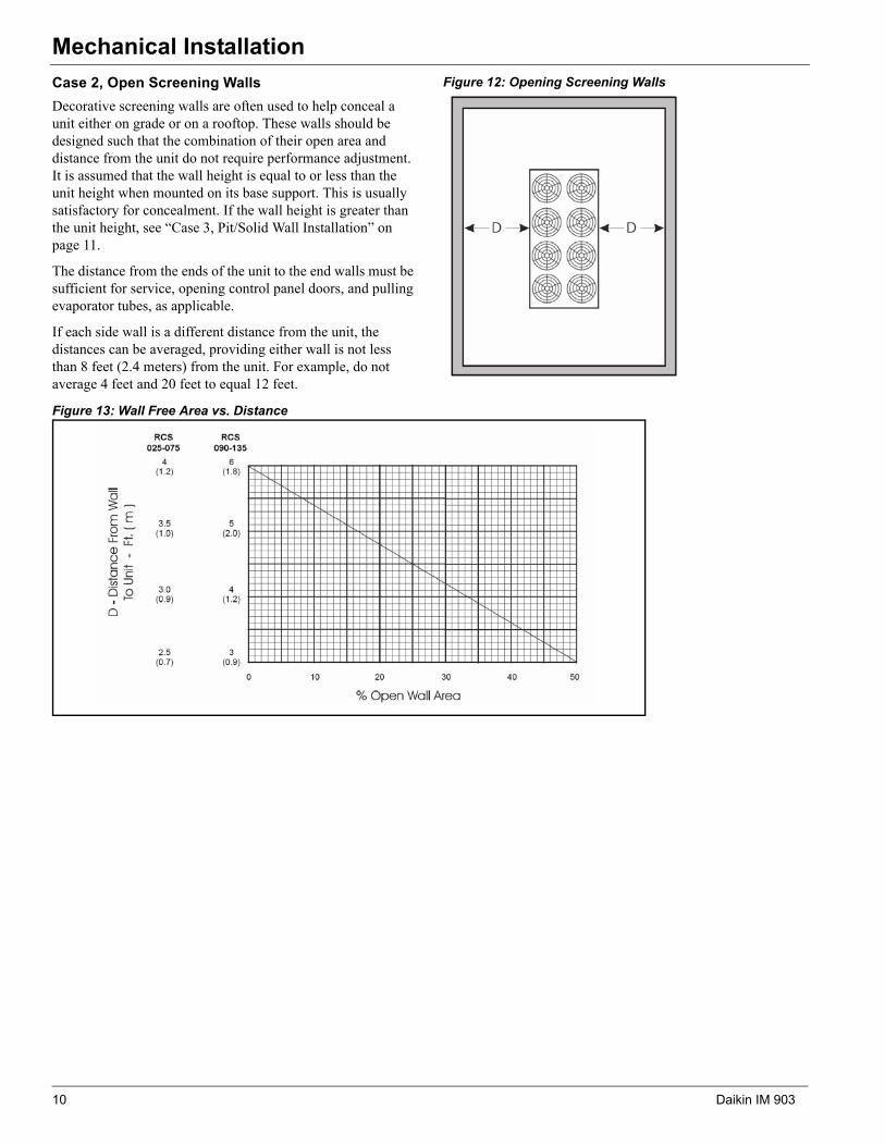
Electrical InstallationField Power Wiring
Wiring must comply with all applicable codes and ordinances. The warranty is voided if wiring is not in accordance with these specifications. An open fuse, tripped circuit breaker, or Manual Motor Protector (MMP) indicates a short, ground, or overload. Before replacing a fuse, circuit breaker, MMP, or restarting a compressor or fan motor, identify the trouble and correct.
According to the National Electrical Code, a disconnecting means shall be located within sight of and readily accessible from the air conditioning equipment. The unit can be ordered with an optional factory mounted disconnect switch. This switch is not fused. Power leads must be over-current protected at the point of distribution. The maximum allowable overcurrent protection (MROPD) appears on the unit nameplate.
In compliance with the National Electrical Code, an electrically isolated 115 V circuit is provided in the unit to supply the factory mounted service receptacle outlet and optional unit lights. This circuit is powered by a field connected 15 A, 115 V power supply. Leads are brought into the RCS unit through a 7/8" knockout in the bottom of the main control panel, near the power wire entry point.
Figure 21: RCS 025C–030C Power Wiring Connections
Figure 22: RCS 040C and 135C Power Wiring Connections
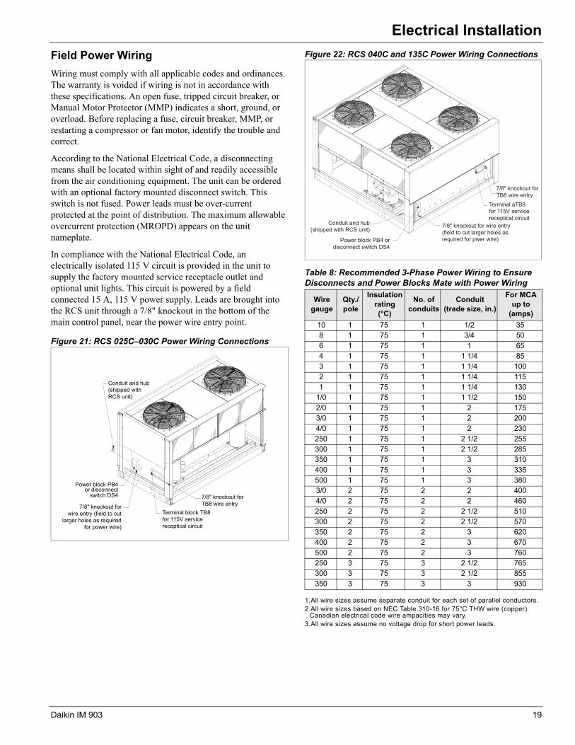
1.All wire sizes assume separate conduit for each set of parallel conductors.2.All wire sizes based on NEC Table 310-16 for 75°C THW wire (copper).
Canadian electrical code wire ampacities may vary.3.All wire sizes assume no voltage drop for short power leads.
Conduit and hub(shipped withRCS unit)
Terminal block TB8for 115V servicereceptical circuit
7/8" knockout forTB8 wire entry
switch DS4or disconnect
Power block PB4
7/8" knockout forwire entry (field to cut
larger holes as requiredfor power wire)
Table 8: Recommended 3-Phase Power Wiring to Ensure Disconnects and Power Blocks Mate with Power Wiring
Wire gauge
Qty./pole
Insulation rating (°C)
No. of conduits
Conduit (trade size, in.)
For MCA up to
(amps)
10 1 75 1 1/2 358 1 75 1 3/4 506 1 75 1 1 654 1 75 1 1 1/4 853 1 75 1 1 1/4 1002 1 75 1 1 1/4 1151 1 75 1 1 1/4 130
1/0 1 75 1 1 1/2 1502/0 1 75 1 2 1753/0 1 75 1 2 2004/0 1 75 1 2 230250 1 75 1 2 1/2 255300 1 75 1 2 1/2 285350 1 75 1 3 310400 1 75 1 3 335500 1 75 1 3 3803/0 2 75 2 2 4004/0 2 75 2 2 460250 2 75 2 2 1/2 510300 2 75 2 2 1/2 570350 2 75 2 3 620400 2 75 2 3 670500 2 75 2 3 760250 3 75 3 2 1/2 765300 3 75 3 2 1/2 855350 3 75 3 3 930
Power block PB4 ordisconnect switch DS4
7/8" knockout forTB8 wire entry
Terminal aTB8for 115V servicereceptical circuit
7/8" knockout for wire entry(field to cut larger holes asrequired for pwer wire)
Conduit and hub(shipped with RCS unit)
Daikin IM 903 19

Wiring Diagrams
Wiring DiagramsFigure 23: RCS 025C Typical Controls Power Wiring Diagram
200/ H200
1. Field wiring
3. Shielded wire/cable
4. Main control boxterminals
5. Auxilliary box terminals
6. Field terminals
7. Plug connector
8. Wire/harness number
General Notes
2. Factory wiring
9. Wire nut/IDWN7
20 Daikin IM 903
Wiring Diagrams
Daikin IM 903 21

Wiring Diagrams
Figure 24: RCS 025C Typical Power Wiring Diagram
22 Daikin IM 903

Wiring Diagrams
Daikin IM 903 23

Unit Options
fan speed accordingly. When the pressure rises, SpeedTrol increases the fan speed; when the pressure falls, SpeedTrol decreases the fan speed. The SpeedTrol controller's throttling range is 140 to 200 psig (1212 to 1318 kPa) fixed.
The SpeedTrol fan motor is a single phase, 208/240-volt, thermally protected motor specially designed for variable speed application. Units with 460-volt power have a transformer mounted inside the condenser fan compartment to step the voltage down to 230 volts for the SpeedTrol motor. A portion of a typical SpeedTrol power circuit schematic is shown in Figure 25.
Unit Options
SpeedTrol™
Daikin's SpeedTrol system of head pressure control operates in conjunction with FanTrol by modulating the motor speed of the last condenser fan of each refrigeration circuit in response to condenser pressure. By varying the speed of the last condenser fan of each refrigeration circuit, the SpeedTrol option allows mechanical cooling operation in ambient temperatures down to 0°F (-18°C) provided the unit is not exposed to windy conditions. The system designer is responsible for assuring the condensing section is not exposed to excessive wind or air circulation. SpeedTrol controllers SC11 and SC21 sense refrigerant head pressure and vary the
Figure 25: SpeedTrol Schematic
HCF11-1
HCF11-2
HCF11-3
HCF21-1
HCF21-2
HCF21-3
H739-2
H741-2
HCF11-S1
HCF11-S3
HCF21-S1
HCF21-S3
H738-2
H740-2
832
865
MTR
MTR
24V
24V
L3
L2
L1
L3
L2
L1
L1
M1
12
L1
M1
12
21
21
1111111
1111111
3-2 3-1
T3L3
T1L1
T3L3
T1L1
L2
L1
T2
T1
L2
L1
T2
T1
COND-FAN11+NB
COND-FAN21+NB
+NBSC11
+NBSC21
C11
C21
M11
M21
F11
F12
4L14
764-1
4L13 762-1
4L14
759-1
4L13 757-1
24 Daikin IM 903

Check, Test, and Start Procedures
Check, Test, and Start ProceduresTo obtain full warranty coverage, complete and sign the check, test, and start form supplied with the unit and return it to Daikin Applied.
A representative of the owner or the operator of the equipment should be present during start-up to receive instructions in the operation, care, and maintenance of the unit.
If the unit has a factory mounted disconnect switch, use the switch’s bypass mechanism to open the main control panel door without de-energizing the control panel.
Servicing Control Panel Components
Always inspect units for multiple disconnects to ensure all power is removed from the control panel and its components before servicing.
Before Start-up1 Verify that the unit is completely and properly installed.
2 Verify that all construction debris is removed.
3 Verify that all electrical work is complete and properly terminated.
4 Verify that all electrical connections in the unit control panel and compressor terminal box are tight, and that the proper voltage is connected.
5 Verify all nameplate electrical data is compatible with the power supply.
6 Verify the phase voltage imbalance is no greater than 10%.
7 Manually rotate all fans and verify that they rotate freely.
8 Verify that all setscrews and fasteners on the fan assemblies are still tight.
9 Before attempting to operate the unit, review the control layout description to become familiar with the control locations.
10 Review the equipment and service literature, the sequences of operation, and the wiring diagrams to become familiar with the functions and purposes of the controls and devices.
11 Determine which optional controls are included with the unit.
DANGER
Hazardous voltage. Will cause equipment damage, severe personal injury, or death.Disconnect and tag out all electrical power before servicing this equipment.All start-up and service work must be performed only by trained, experienced technicians familiar with the hazards of working on this type of equipment.Bond the equipment frame to the building electrical ground through grounding terminal or other approved means.
DANGER
Hazardous voltage. Will cause severe injury or death.Disconnect electric power before servicing equipment. More than one disconnect may be required to de-energize the unit.
Daikin IM 903 25

Check, Test, and Start Procedures
Compressor Startup
There should be adequate building load (at least 50 percent of the unit full load capacity) to properly check the operation of the unit’s refrigerant circuits.
Record all operating parameters required by the “Compressorized Equipment Warranty Form”. Return this information within 10 working days to Daikin Applied as instructed on the form to register the start-up date with the Daikin Warranty Department.
With the supply and return fans operational, prepare for compressor operation.
The unit is shipped with refrigeration service valves closed. Backseat (open) the discharge (suction on sizes 115 to 135), and liquid line valves. Connect service gauges and crack the valves off the backseat position (one turn forward). Verify that the unit has not lost its refrigerant charge.
Verify that the crankcase heaters are operating. These should operate for at least 24 hours before starting the compressors.
Verify that the condenser fan blades are positioned properly and that the screws are tight (see Figure 26). The fan blade must be correctly positioned within its orifice for proper airflow across the condenser coils.
Figure 26: Condenser Fan Blade Positioning
Scroll Compressor RotationalDirection (025C to 105C)
Scroll compressors only compress in one rotational direction. Three-phase compressors rotate in either direction depending
upon phasing of the power to L1, L2, and L3. Since there is a 50/50 chance of connecting power to cause rotation in the reverse direction, verify that the compressor rotates in the proper direction after the system is installed. If the compressor is rotating properly, suction pressure drops and discharge pressure rises when the compressor is energized. If the compressor is rotating in reverse, the sound level is louder and current draw is reduced substantially. After several minutes of operation, the compressor’s internal protector trips.
All three-phase compressors are wired the same internally. Therefore, once the correct phasing is determined for a specific system or installation, connecting properly phased power leads to the same terminals should maintain proper rotation direction.
Expansion Valve Superheat Adjustment
It is very important that the expansion valve superheat setting be adjusted to be between 10°F (-12°C) and 13°F (-11°C). Insufficient superheat will cause liquid floodback to the compressor which may result in slugging. Excessive superheat will reduce system capacity and shorten compressor life.
Turn the adjustment stem clockwise to increase superheat. Not exceeding one turn, adjust the stem and then observe the superheat. Allow up to 30 minutes for the system to rebalance at the final superheat setting.
On refrigeration circuits with multiple expansion valves, the superheat adjustment should be approximately the same for all valves in the circuit.
R-407C Superheat
Due to refrigerant glide, when measuring and/or adjusting TEV superheat, it is important to use SATURATED VAPOR (Dew Point) TABLES. Example: The Pressure/Temperature (P/T) chart shows that the saturated vapor temperature, at the dew point, of R-407C for 79 psig is approximately 51°F. If the actual refrigerant temperature is 60°F, the superheat is 9°F.
Checking Superheat
Following are recommendations for checking superheat:
1 Close the unit section doors. Running the unit with its doors open will affect expansion valve and system operation considerably.
2 For units with one expansion valve per circuit, check the pressure and temperature at the compressor suction valve.
3 For units with multiple expansion valves per circuit, check the pressure at the compressor, and check the temperature at the suction header that is fed by the valve.
CAUTION
Electrical power must be applied to the compressor crankcase heaters 24 hours before starting unit to expel refrigerant from the oil, otherwise compressor damage may occur.
CAUTION
Low ambient temperature hazard. Can cause compressor damage.Do not attempt to start up and check out the refrigeration system when the outdoor air temperature is below 50°F unless the unit is specially equipped for low ambient operation.
1.21"
26 Daikin IM 903

Check, Test, and Start Procedures
Oil Pressure (115C to 135C only)
When the compressor has operated long enough to stabilize conditions, proper oil pressure should be maintained. The actual oil pressure value varies from compressor to compressor and depends upon the temperature, oil viscosity, compressor size, and the amount of clearance in the compressor bearings. Oil pressure values from 20 to 60 psi (138-414 kPa) (over suction pressure) are not uncommon.
The oil level in the compressor sightglass can vary widely and depends upon the same factors listed above. In fact, it is not unusual for two compressors that serve the same circuit to have very different oil levels. Therefore, it is recommended that oil pressure, not sightglass level, be used to judge whether there is enough oil in a refrigerant circuit. If the oil pressure is low, add additional. Refer to page 18 to find acceptable refrigerant oils.
Note: If low oil level is accompanied by heavy foaming visible in the oil sightglass, it is possible that excess liquid refrigerant is returning to the compressor depending on the rotation of the crank shaft. Check the suction superheat and adjust the expansion valve for 10°F (-12°C) to 13°F (-11°C) of superheat. If proper superheat is obtained, sightglass foaming is not a concern.
Refrigerant Piping Checkout
1. Check all exposed brazed joints on the unit, as well as anyfield-installed piping, for evidence of leaks. Joints can havebeen damaged during shipping or when the unit was installed.
2. Check that all refrigerant valves are either opened or closedas required for proper operation of the unit.
3. A thorough leak test must be done using an approvedelectronic leak detector. Check all valve stem packing forleaks. Replace all refrigerant valve caps and tighten.
4. Check all refrigerant lines to see that they will not vibrateagainst each other or against other unit components and areproperly supported.
5. Check all flare connections and all refrigerant threadedconnectors.
6. Look for any signs of refrigerant leaks around the condensercoils and for damage during shipping or installation.
7. Leak detector is applied externally to refrigerant joints at thefactory. Do not confuse this residue with an oil leak.
8. Connect refrigerant service gauges to each refrigerant circuitbefore starting unit.
Electrical Checkout
1 Open all electrical disconnects and check all power wiring connections. Start at the power block and check all connections through all components to and including the compressor terminals. These should be checked again after 3 months of operation and at least annually thereafter.
2 Check all control wiring and tighten all screw connections. Check plug-in relays for proper seating and that retaining clips are installed.
3 Apply power to the unit.
4 Check at the power block or disconnect for the proper voltage and for the proper voltage between phases. Check power for proper phasing using a phase sequence meter before starting unit.
5 Check for 120 V (ac) at the control transformer and at TB1A1 and TB1A5.
6 Check between TB1E28 and TB1E30 for 24 V (ac) control voltage.
CAUTION
Electrical power must be applied to the compressor crankcase heaters 24 hours before starting the unit to drive off refrigerant from the oil or compressor damage can occur.
Daikin IM 903 27

Operation
OperationHot Gas Bypass (Optional)
This option allows the system to operate at lower loads without excessive on/off compressor cycling. The hot gas bypass option is required to be on both refrigerant circuits because of the lead/lag feature of the controller.
This option allows passage of discharge gas into the evaporator inlet (between the TX valve and the evaporator) which generates a false load to supplement the actual chilled water or air handler load.
Note: The hot gas bypass valve cannot generate a 100% false load.
The valve that is supplied can provide a load of approximately 10 tons. The system load added to the ten tons of the hot gas bypass valve has to exceed the compressor capacity for stage 1 compressors to produce stable system operation. This requires 3-6 tons of system load.
The MicroTech II controls solenoid valves in the hot gas bypass lines that are energized whenever their circuit is operating with only one compressor running. The hot gas bypass valve is regulated by the evaporator pressure and the remote adjustable bulb. The pressure regulating valve is factory set to begin opening at 58 psig (32°F for R-22).
System Adjustment
To maintain peak performance at full load operation, the system superheat and liquid subcooling can require adjustment. Read the following subsections closely to determine if adjustment is required.
Liquid Line Sight Glass and Moisture Indica-tor
The color of the moisture indicator is an indication of the dryness of the system and is extremely important when the system has been serviced. Immediately after the system has been opened for service, the element can indicate a wet condition. It is recommended that the equipment operate for about 12 hours to allow the system to reach equilibrium before deciding if the system requires a change of drier cores.
Bubbles in the sight glass at constant full load indicates a shortage of refrigerant, a plugged filter drier, or a restriction in
the liquid line. However, it is not unusual to see bubbles in the sight glass during changing load conditions.
Refrigerant Charging
Liquid line subcooling at the liquid shut-off valve should be between 15°F and 20°F at full load. If the unit is at steady full load operation and bubbles are visible in the sight glass, then check liquid subcooling.
Thermostatic Expansion Valve
The expansion valve performs one specific function. It keeps the evaporator supplied with the proper amount of refrigerant to satisfy the load conditions.
The sensing bulb of the expansion valve is installed in the closest straight run of suction line from the evaporator. The bulb is held on by clamps around the suction line and is insulated to reduce the effect of surrounding ambient temperatures. In case the bulb must be removed, simply slit the insulation on each side of the bulb, remove the clamps and then remove the capillary tubing that runs along the suction line from the valve.
The power element is removable from the valve body without removing the valve from the line.
Note: Before adjusting superheat, check that unit charge is correct and liquid line sight glass is full with no bubbles and that the circuit is operating under stable, full load conditions.
The suction superheat for the suction leaving the evaporator is set at the factory for 8°F to 12°F at full load. To have full rated unit performance, the superheat must be about 8°F at 95°F outdoor ambient temperature.
Crankcase Heaters
The scroll compressors are equipped with externally mounted band heaters located at the oil sump level. The function of the heater is to keep the temperature in the crankcase high enough to prevent refrigerant from migrating to the crankcase and condensing in the oil during off-cycle.
WARNING
Be careful during valve checkout. The hot gas line can become hot enough to cause personal injury.
CAUTION
Electrical power must be applied to the compressor crankcase heaters 24 hours before starting the unit to drive off refrigerant from the oil or compressor damage can occur.
28 Daikin IM 903

Maintenance
MaintenanceInstallation and maintenance must be performed only by qualified personnel who are experienced with this type of equipment and familiar with local codes and regulations.
Servicing Control Panel Components
Disconnect all electric power to the unit when servicing control panel components. Before servicing, always inspect units for multiple disconnects to ensure all power is removed from the control panel and its components.
Planned Maintenance
Preventive maintenance is the best way to avoid unnecessary expense and inconvenience. Have this system inspected at regular intervals by a qualified service technician. The required frequency of inspections depends upon the total operating time and the indoor and outdoor environmental conditions. Routine maintenance should cover the following items:
• Tighten all wire connections.
• Clean condenser coils with cold water, if necessary. Usuallyany fouling is only matted on the entering air face of the coiland can be removed by brushing.
• Check each circuit’s refrigerant sightglass when the circuit isoperating under steady-state, full load conditions. Thesightglass should then be full and clear. If it is not, check forrefrigerant leaks.
Note: A partially full sight glass is not uncommon at part load conditions.
• Check for proper superheat.
• Check the power and control voltages.
• Check the running amperage of all motors.
• Check all operating temperatures and pressures.
• Check and adjust all temperature and pressure controls asneeded.
• Check the operation of all safety controls.
• Check the condenser fans and tighten their setscrews.
• Lubricate the door latch mechanisms.
Unit Storage
Location
The RCS unit is an outdoor unit. However, the schedule may dictate storage either on the ground or in its final position at the site. If the unit is stored on the ground, additional precautions should be taken as follows:
• Make sure that the unit is level (no twists or uneven groundsurface).
• Provide proper drainage around the unit to prevent floodingof the equipment.
• Provide adequate protection from vandalism, mechanicalcontact, etc. The condenser fins are particularly vulnerableto damage by even light contact with ground based objects.
• Make sure all doors are securely closed.
Preparation
Control Box
Once a month, open the control box and verify that no moisture or debris is accumulating in the unit.
Cooling circuits
The steps below are necessary only if the unit has been started.
1 Provide that each circuit is properly pumped down.
2 Turn off the compressor MMP.
3 Close all the refrigerant service valves on each circuit.
4 Tag the valves as a warning for the technician who restarts the units.
Restart
After extended storage, perform a complete start up. Inevitable accumulations of dirt, insect nests, etc. can contribute to problems if not cleaned out thoroughly prior to start up. In addition, thermal cycling tends to loosen mechanical and electrical connections. Following the startup procedure helps discover these and other issues that may have developed during the storage interval.
Refrigerant Charge
The unit nameplate references proper charge for each refrigerant circuit in case a full charge must be added to the unit. Verify these values using pages 14–16.
DANGER
Moving machinery and electrical power hazards. Will cause severe personal injury or death.Disconnect and lock off all power before servicing equipment.
WARNING
Sharp edges are inherent to sheet metal parts, screws, clips, and similar items. Can cause personal injury.Exercise caution when servicing equipment.
DANGER
Hazardous voltage. Will cause severe injury or death.Disconnect electric power before servicing equipment. More than one disconnect may be required to de-energize the unit.
WARNING
Potential severe loss of charge may occur if the high refrigerant pressure switch is replaced before reclaiming the refrigerant. Replace switch after reclaiming refrigerant.
Daikin IM 903 29
Maintenance
Servicing Refrigerant Sensors or Switches
The Daikin Rooftop unit includes the following refrigerant sensors or switches.
1 Low refrigerant pressure sensing, operating switch, automatic reset.
a Disables their associated compressors on a drop in suction pressure to approximately 35 psig.
b Enables their associated compressors on a rise in suction pressure to approximately 60 psig.
2 SpeedTrol™ high refrigerant pressure sensor (not available on sizes 025C to 030C), see page 24 for more information.
3 High refrigerant pressure, protective switch, manual reset, reset by breaking control power to the S1 control switch.
a Scroll compressor units (sizes 025C to 105C) = 425 psig
b Reciprocating compressor units (sizes 025C to 135C) = 400 psig
c The switches have a differential of 100 psig.
4 High pressure relief, protective valve on sizes 115C to 135C only and located on the condenser headers.
The low pressure and SpeedTrol sensors/ switches sense refrigerant pressure through shrader fittings that contain cores. The cores are stop valves that do not allow refrigerant to flow through the shrader unless the device is in place. Therefore the low pressure and SpeedTrol sensors/switches can be replaced without reclaiming the refrigerant.
The Shrader that serves the high pressure switch does not contain a core in order to maximize the functionality of the safety. Therefore it cannot be replaced unless the refrigerant has already been reclaimed.
Control Panel Components
Manual Motor Protector (MMP)
The manual motor protector (MMP) provides coordinated branch circuit, short circuit protection, a disconnecting means, a motor controller, and coordinated motor overload protection. A short circuit indicator with manual reset is mounted along side of each MMP as a means to differentiate between a short circuit and overload trip conditions.
The MMP trip points are factory set. Do not change unless the motor ampacity changes or the MMP is replaced with a new device with incorrect setpoint adjustment. Any other non-authorized trip point or setpoint adjustment voids all or portions of the unit’s warranty. Authorized setpoint adjustment is accomplished as follows
1 For motors with a 1.15 service factor, rotate the arrow on the dial to correspond to the motor FLA.
2 For motors with a 1.0 service factor, multiply the motor FLA by 0.9; then rotate the arrow on the dial to correspond to that value.
To reset a tripped MMP, clear the trip by rotating the knob counterclockwise to the OFF position; then rotate knob clockwise to the ON position.
Other MMP features:
• Three-position rotary operator: OFF-TRIP-ON.
• Lockout—tagoutable rotary operator: turn the rotaryoperator to OFF, slide out the extension arm, and insert alockout pin.
• Ambient compensated –20°F to +60°F.
• Single-phase sensitivity: if one phase exceeds setpoint, allthree phases open.
• Trip test: insert a 9/64" screw driver in the test slot tosimulate a trip.
WARNING
If an overload or a fault current interruption occurs, check circuits to determine the cause of the interruption. If a fault condition exits, examine the controller. If damaged, replace it to reduce the risk of fire or electrical shock.
30 Daikin IM 903

Maintenance
Disconnect
The optional disconnect is a “through-the-door” molded case switch with similar features of the circuit breaker. The “through-the-door” feature provides a safety interlock that disables power when an inexperienced person opens the control panel door. This is not the normal recommended method to access the control panel or to disable power to an operating unit.
Depending on the desired operating state of the unit, four different recommended methods can be utilized to access the control panel or to disable power.
1 Recommended method to access the controls through the “release” method (defeats the mechanical interlock and allows the control panel door to open without disconnecting power - switch is in the power “On” position):
a Obtain a small standard head screwdriver.
b Insert the head of the screwdriver into the slotted “release” located on the right hand side of the disconnect faceplate (Figure 27). Turn the release counter-clockwise.
c Pull open the door after the mechanical interlock is released.
2 Recommended normal method to turn off an operating unit (no emergency condition present):
a Follow the “release” method described above.
b Use the pump down switch to turn off the unit.
c The controls will then shut the liquid line solenoids, pump the refrigerant into the condenser, and turn off the compressors.
3 Recommended method to “lock off” power while the disconnect is off:
a Rotate the handle to the “Reset Lock” position.
b Manually push in the lockout mechanism into the slot on the faceplate.
c Insert a padlock into the lockout hole located on the disconnect handle.
d Test rotate the handle to insure that power “lockout” is provided.
4 Recommended normal method to “restore” power to a unit that is locked out:
a Unlock and remove the padlock when it is safe (doors are shut, no personnel are within reach of the condensing unit or are inside the air handler).
b Shut the control panel door and ensure the interlock mechanism is operable.
c Rotate the handle to the “On” position.
Figure 27: Through-the-Door Handle Disconnect
DANGER
Hazardous voltage. Will cause severe injury or death.Disconnect electric power before servicing equipment. More than one disconnect may be required to de-energize the unit.
CAUTION
Molded case switches do not provide over-current protection. This device may automatically open the circuit at levels above the ampere rating of the switch.
Daikin IM 903 31
Maintenance
Terminals
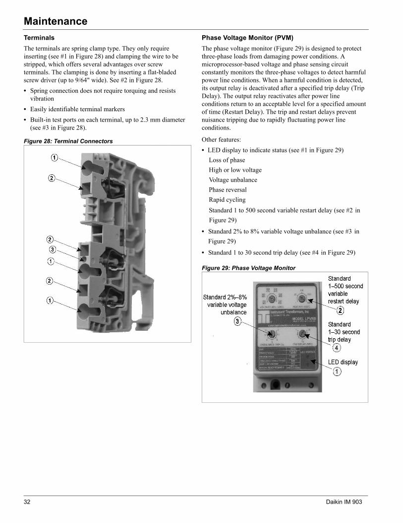
The terminals are spring clamp type. They only require inserting (see #1 in Figure 28) and clamping the wire to be stripped, which offers several advantages over screw terminals. The clamping is done by inserting a flat-bladed screw driver (up to 9/64" wide). See #2 in Figure 28.
• Spring connection does not require torquing and resistsvibration
• Easily identifiable terminal markers
• Built-in test ports on each terminal, up to 2.3 mm diameter(see #3 in Figure 28).
Figure 28: Terminal Connectors
Phase Voltage Monitor (PVM)
The phase voltage monitor (Figure 29) is designed to protect three-phase loads from damaging power conditions. A microprocessor-based voltage and phase sensing circuit constantly monitors the three-phase voltages to detect harmful power line conditions. When a harmful condition is detected, its output relay is deactivated after a specified trip delay (Trip Delay). The output relay reactivates after power line conditions return to an acceptable level for a specified amount of time (Restart Delay). The trip and restart delays prevent nuisance tripping due to rapidly fluctuating power line conditions.
Other features:
• LED display to indicate status (see #1 in Figure 29)
Loss of phase
High or low voltage
Voltage unbalance
Phase reversal
Rapid cycling
Standard 1 to 500 second variable restart delay (see #2 inFigure 29)
• Standard 2% to 8% variable voltage unbalance (see #3 inFigure 29)
• Standard 1 to 30 second trip delay (see #4 in Figure 29)
Figure 29: Phase Voltage Monitor
32 Daikin IM 903

Service and Warranty Procedure
Service and Warranty ProcedureReplacement Parts
When writing to Daikin for service or replacement parts, provide the model number, serial number, and unit part number of the unit as stamped on the serial plate attached to the unit. For questions regarding wiring diagrams, it will be necessary to provide the number on the specific diagram. If replacement parts are required, include the date of unit installation, the date of failure, an explanation of the malfunction, and a description of the replacement parts required.
Scroll Compressor (025C to 105C)
Daikin Rooftops use the following Copeland Scroll Compressors.
1 Single compressors, one per refrigerant circuit.
2 Tandem compressors, basically two compressors specifically manufactured by Copeland into a single assembly.
3 Trio compressors, basically three single compressors factory piped in parallel with equalization lines.
All Daikin Rooftop products include a first-year parts only warranty. The warranty period extends 12 months from startup or 18 months from date of shipment, whichever comes first. Labor to install these parts is not included with this warranty. Compressors are considered a part and are included in this standard warranty.
Scroll service replacement compressors for Daikin Rooftop Units can be obtained from the following two sources:
• Daikin Service Parts maintains a stock of replacement compressors.
• Copeland Refrigeration has stocking wholesalers throughout the U.S. who maintain a limited stock of replacement scroll compressors. The stock of single compressors is much better than the stock of tandems “tandem/trio ready”, single compressors. Trios are almost never in wholesaler stock and are not recommended for use on Daikin Rooftops due to piping interference. Copeland does offer quick ship options though their wholesalers.
Both sources can be used, at the customer’s discretion, within the first year warranty and with the following limitations.
1 RCS 025C to 030C (with single and tandem compressors).
a If any part of the tandem fails then the entire tandem must be replaced. Both sources are acceptable.
b Single compressor. No limitations.
c Circuit #1 tandem - If any part of the tandem fails then the entire tandem must be replaced. Both sources are acceptable.
d Circuit #2 tandem–Each of the tandem’s compressors have a rotalock and only the failed portion of the tandem may need replacement.
2 RCS 040C to 060C—Each of the tandem’s compressors have a rotalock and only the failed portion of the tandem may need replacement.
3 RCS 070C to 105C—Each of the trio compressors have a rotalock and only the failed portion of the trio may need replacement.
4 Only a “tandem or trio ready” compressor, with oil equalizer lines, can be used to replace a portion of the tandem or trio.
Reciprocating Compressors (115C to 135C)
Daikin Rooftops use Copeland Discus™ compressors mounted in “tandem.”
Tandem compressors are basically two single compressors factory piped in parallel with equalization lines.
All Daikin Rooftop products include a first year parts only warranty. The warranty period extends 12 months from start-up or 18 months from date of shipment, whichever comes first. Labor to install these parts is not included with this warranty. Compressors are considered a part and are included in this standard warranty.
If the equipment experiences a compressor failure within the first year parts warranty period or is a “dead” on arrival (DOA) compressor at start-up, the failed compressor is covered under the first year parts warranty. To receive a replacement compressor:
1 Notify the local (Copeland) wholesaler of the failure and provide the compressor model and serial number.
2 The customer/contractor picks up the replacement compressor from the wholesaler.
3 After removing the failed compressor from the equipment, return it to the local wholesaler for credit on the replacement compressor.
4 Consideration may be given at this time to a compressor teardown analysis, depending on the history of failures.
Daikin IM 903 33
Service and Warranty Procedure
All Compressors
The decision to replace the failed portion of the tandem or trio, as opposed to replacing the entire tandem or trio, must be decided based on the following.
1 The entire tandem must be replaced if the individual portions do not include rotalocks and rotalocks are not available on the RCS 025 to 030 (tandems and the RCS circuit #1 tandem).
2 In warranty: Warranty only covers replacement of the failed portion of the tandem or trio. Either source may be used.
3 Out of warranty: The customer decides whether to replace the entire tandem/trio or just a portion and either source may be used.
When replacing an “in warranty” compressor through a Copeland Wholesaler, take the failed compressor to the wholesaler for an over-the-counter or an advanced replacement exchange. Credit is issued by Copeland on the returned motor compressor upon receipt and factory inspection of the inoperative motor compressor. In this transaction, be certain that the motor compressor is definitely defective. If a motor compressor is received from the field that tests satisfactorily, a service charge plus a transportation charge will be charged against its original credit value.
If there was a delay in the startup of the equipment and the first-year warranty (Copeland) has expired on the compressor, within the 18-month-from-shipment warranty, order the replacement compressor through the Daikin Parts Department (Minneapolis).
1 Contact the Daikin Parts Department for compressor availability.
2 Send a completed parts order form to the Daikin Parts Department.
3 The Parts Department processes the order and the compressors are shipped from our Dayton, OH warehouse via ground transportation. If next-day air is required, indicate this on the parts order form and a freight charge will be billed to your account. Air freight costs are not covered under the Daikin warranty.
4 After the failed compressor is replaced, return it to Daikin International with a Return Goods Tag attached, which you will receive in the mail. It must be attached to the compressor. The Return Goods Tag has instructions on where to send the compressor. If the compressor is not returned, you will be billed for the replacement compressor.
5 Consideration may be given at this time to a compressor teardown analysis, depending on the history of failures.
On Daikin equipment that includes the extended 2nd -5th year compressor warranty option, the replacement compressor must be ordered through the Daikin Parts Department (Minneapolis).
1 Contact the Daikin Parts Department for compressor availability.
2 Send the Daikin Parts Department a completed parts order form.
3 The Parts Department will process the order and the compressors will be shipped from our Dayton, OH warehouse via ground transportation. If next-day air is required, you will need to indicate this on the parts order form and a freight charge will be billed to your account. Air freight costs are not covered under the Daikin warranty.
4 After the failed compressor has been replaced, it must be returned to Daikin Applied with a Return Goods Tag attached. You will receive the tag in the mail and it must be attached to the compressor. The Return Goods Tag will have instructions on where to send the compressor. If the compressor is not returned, you will be billed for the replacement compressor.
5 Consideration may be given at this time to a compressor teardown analysis, depending on the history of failures.
In-Warranty Return Material Procedure
Material other than compressors may not be returned except by permission of authorized factory service personnel of Daikin Applied at Minneapolis, Minnesota.
A “return goods” tag will be sent to be included with the returned material. Enter the information as called for on the tag in order to expedite handling at out factories and issuance of credits. All parts shall be returned to the factory designated on the return goods tag, transportation charges prepaid.
The return of the part does not constitute an order for replacement. A purchase order for the replacement part must be entered through your nearest Daikin representative. The order should include the component's part number and description and the model and serial numbers of the unit involved.
If it is determined that the failure of the returned part is due to faulty material or workmanship within the standard warranty period, credit will be issued on the customer's purchase order.
34 Daikin IM 903

Limited Product Warranty (North America)
Limited Product Warranty (North America)Daikin Apllied (“Company”) warrants to contractor, purchaser and any owner of the product (collectively “Owner”) that Company, at its option, will repair or replace defective parts in the event any product manufactured by Company, including products sold under the brand names Daikin Air Conditioning, AAF Air Conditioning, AAF HermanNelson and Daikin Applied, and used in the United States or Canada, proves defective in material or workmanship within twelve (12) months from initial startup or eighteen (18) months from the date shipped by Company, whichever occurs first. Authorized replaced parts are warranted for the duration of the original warranty. All shipments of such parts will be made FOB factory, freight prepaid and allowed. Company reserves the right to select carrier and method of shipment.
In addition, labor to repair or replace warranty parts is provided during Company normal working hours on products with rotary screw compressors, centrifugal compressors and on absorption chillers. Warranty labor is not provided for any other products.
Company’s liability to Owner under this warranty shall not exceed the lesser of the cost of correcting defects in the products sold or the original purchase price of the products.
PRODUCT STARTUP ON ABSORPTION, CENTRIFUGAL AND SCREW COMPRESSOR PRODUCTS IS MANDATORY and must be performed by Daikin Service or a Company authorized service representative.
It is Owner’s responsibility to complete and return the Registration and Startup Forms accompanying the product to Company within ten (10) days of original startup. If this is not done, the ship date and the startup date will be deemed the same for warranty period determination, and this warranty shall expire twelve (12) months from that date.
Exceptions1 If free warranty labor is available as set forth above, such
free labor does not include diagnostic visits, inspections, travel time and related expenses, or unusual access time or costs required by product location.
2 Refrigerants, fluids, oils and expendable items such as filters are not covered by this warranty.
3 This warranty shall not apply to products or parts which (a) have been opened, disassembled, repaired, or altered byanyone other than Company or its authorized servicerepresentative; or (b) have been subjected to misuse,negligence, accidents, damage, or abnormal use or service;or (c) have been operated, installed, or startup has beenprovided in a manner contrary to Company’s printedinstructions, or (d) were manufactured or furnished byothers and which are not an integral part of a productmanufactured by Company; or (e) have not been fully paidfor by Owner.
Assistance
To obtain assistance or information regarding this warranty, please contact your local sales representative or Daikin Service office.
Sole Remedy/Disclaimer
THIS WARRANTY CONSTITUTES THE OWNER’S SOLE REMEDY. IT IS GIVEN IN LIEU OF ALL OTHER WARRANTIES. THERE IS NO IMPLIED WARRANTY OF MERCHANTABILITY OR FITNESS FOR A PARTICULAR PURPOSE. IN NO EVENT AND UNDER NO CIRCUMSTANCE SHALL COMPANY BE LIABLE FOR INCIDENTAL, INDIRECT, SPECIAL, CONTINGENT OR CONSEQUENTIAL DAMAGES, WHETHER THE THEORY BE BREACH OF THIS OR ANY OTHER WARRANTY, NEGLIGENCE OR STRICT LIABILITY IN TORT.
No person (including any agent, sales representative, dealer or distributor) has the authority to expand the Company’s obligation beyond the terms of this express warranty or to state that the performance of the product is other than that published by Company.
For additional consideration, Company will provide an extended warranty(ies) on certain products or components thereof. The terms of the extended warranty(ies) are shown on a separate extended warranty statement.
Daikin IM 903 35

RCS Rooftop Equipment Warranty Registration Form
RCS Rooftop Equipment Warranty Registration FormTo comply with the terms of Daikin Warranty, complete and return this Equipment Warranty Registration Form within 10 days to Daikin Warranty Department
Check, test, and start procedure for RoofPak roof mounted air conditioners with or without heat recovery and roof mounted air handlers.
Job Name: _______________________________________________________________________ Daikin G.O. No.: _________________
Installation address: __________________________________________________________________________________________________
City: _____________________________________________________________________________ State: __________________________
Purchasing contractor: ________________________________________________________________________________________________
City:______________________________________________________________________________ State: __________________________
Name of person doing start-up (print) ____________________________________________________________________________________
Company name _____________________________________________________________________________________
Address ___________________________________________________________________________________________
City/State/Zip _______________________________________________________________________________________
Unit model number:_________________________________________________ Unit serial number:________________________________
Compressor #1 model number: _______________________________________ Serial number:____________________________________
Compressor #2 model number: _______________________________________ Serial number:____________________________________
Compressor #3 model number: _______________________________________ Serial number:____________________________________
Compressor #4 model number: _______________________________________ Serial number:____________________________________
Compressor #5 model number: _______________________________________ Serial number:____________________________________
Compressor #6 model number: _______________________________________ Serial number:____________________________________
Circle Yes or No. If not applicable to the type of unit, circle N/A.
I. INITIAL CHECK
A. Is any shipping damage visible? . . . . . . . . . . . . . . . . . . . . . . . . . . . . . . . . . . . . . . . . . . . . . . . . . . . . . . . . . . . . . . . . . . . Yes No N/A
B. Tightened all setscrews?. . . . . . . . . . . . . . . . . . . . . . . . . . . . . . . . . . . . . . . . . . . . . . . . . . . . . . . . . . . . . . . . . . . . . . . . . Yes No N/A
C. Have the shipping spacers been removed from the compressor springs and have the neoprene spacers beeninstalled on each compressor mounting bolt? (Only applies to 115C–135C units with compressor spring isolators.)
Yes No N/A
D. Electrical service corresponds to unit nameplate? . . . . . . . . . . . . . . . . . . . . . . . . . . . . . . . . . . . . . . . . . . . . . . . . . . . . . Yes No N/A
Volts __________ Hertz __________ Phase __________
E. Is the main disconnect adequately fused and are fuses installed?. . . . . . . . . . . . . . . . . . . . . . . . . . . . . . . . . . . . . . . . . Yes No N/A
F. Are crankcase heaters operating, and have they been operating 24 hours prior to start-up? . . . . . . . . . . . . . . . . . . . . Yes No N/A
G. Are all electrical power connections tight? (Check compressor electrical box.) . . . . . . . . . . . . . . . . . . . . . . . . . . . . . . . Yes No N/A
H. Has the field piping been piped per ASHRAE recommendations?: . . . . . . . . . . . . . . . . . . . . . . . . . . . . . . . . . . . . . . . . Yes No N/A
II. START-UP COMPRESSOR OPERATION
A. Has each circuit been field leak tested?
Circuit 1. . . . . . . . . . . . . . . . . . . . . . . . . . . . . . . . . . . . . . . . . . . . . . . . . . . . . . . . . . . . . . . . . . . . . . . . . . . . . . . . . . . . . . Yes No N/A
Circuit 2. . . . . . . . . . . . . . . . . . . . . . . . . . . . . . . . . . . . . . . . . . . . . . . . . . . . . . . . . . . . . . . . . . . . . . . . . . . . . . . . . . . . . . Yes No N/A
B. Refrigerant charge per circuit: Circuit 1 ________ Circuit 2 ________
C. Backseat discharge, suction (sizes 115C –135C only), and liquid line valves? . . . . . . . . . . . . . . . . . . . . . . . . . . . . . . . Yes No N/A
D. Are compressors rotating in the right direction? . . . . . . . . . . . . . . . . . . . . . . . . . . . . . . . . . . . . . . . . . . . . . . . . . . . . . . . Yes No N/A
E. Do condenser fans rotate in the right direction? . . . . . . . . . . . . . . . . . . . . . . . . . . . . . . . . . . . . . . . . . . . . . . . . . . . . . . . Yes No N/A
F. Ambient temperature: ____________ °F
G. Oil safety control time delay (sizes 115C–135C only): Compressor #1 sec. _______ Compressor #3 sec. _______
Compressor #2 sec. _______ Compressor #4 sec. _______
H. Compressor lockout timers function? . . . . . . . . . . . . . . . . . . . . . . . . . . . . . . . . . . . . . . . . . . . . . . . . . . . . . . . . . . . . . . . Yes No N/A
I. FanTrol functions: TC12 ________ TC13 ________ TC14 ________
J. Part winding start time functions (sizes 115C–135C only):
Compressor: TD1 __________ TD2 __________ TD3__________ TD4 __________
K. Does unit start up and perform per sequence of operation?. . . . . . . . . . . . . . . . . . . . . . . . . . . . . . . . . . . . . . . . . . . . . . Yes No N/A
36 Daikin IM 903
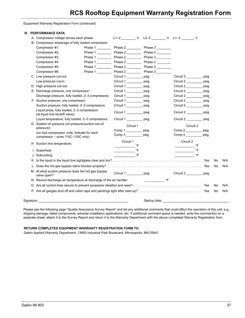
RCS Rooftop Equipment Warranty Registration Form
Equipment Warranty Registration Form (continued)
III. PERFORMANCE DATA
A. Compressor voltage across each phase: L1–2 ________ V L2–3 ________ V L1–3 _______ V
B. Compressor amperage of fully loaded compressor:
Compressor #1: Phase 1 ________ Phase 2 ________ Phase 3 ________
Compressor #2: Phase 1 ________ Phase 2 ________ Phase 3 ________
Compressor #3: Phase 1 ________ Phase 2 ________ Phase 3 ________
Compressor #4: Phase 1 ________ Phase 2 ________ Phase 3 ________
Compressor #5: Phase 1 ________ Phase 2 ________ Phase 3 ________
Compressor #6: Phase 1 ________ Phase 2 ________ Phase 3 ________
C. Low pressure cut-out: Circuit 1 _________ psig Circuit 2 _________ psig
Low pressure cut-in: Circuit 1 _________ psig Circuit 2 _________ psig
D. High pressure cut-out: Circuit 1 _________ psig Circuit 2 _________ psig
E. Discharge pressure, one compressor: Circuit 1 _________ psig Circuit 2 _________ psig
Discharge pressure, fully loaded, 2–3 compressors: Circuit 1 _________ psig Circuit 2 _________ psig_
F. Suction pressure, one compressor: Circuit 1 _________ psig Circuit 2 _________ psig
Suction pressure, fully loaded, 2–3 compressors: Circuit 1 _________ psig Circuit 2 _________ psig
Liquid press, fully loaded, 2–3 compressors(at liquid line shutoff valve):
Circuit 1 _________ psig Circuit 2 _________ psig
Liquid temperature, fully loaded, 2–3 compressors: Circuit 1 _________ psig Circuit 2 _________ psig
G. System oil pressure (oil pressure-suction-net oilpressure):
Circuit 1Comp 1 _________ psigComp 3 _________ psig
Circuit 2Comp 2 _________ psigComp 4 _________ psig
(on four-compressor units, indicate for eachcompressor – sizes 115C–135C only)
H. Suction line temperature:Circuit 1
____________°FCircuit 2
___________ °F
I. Superheat: ____________°F ___________ °F
J. Subcooling: ____________°F ___________ °F
K. Is the liquid in the liquid line sightglass clear and dry? . . . . . . . . . . . . . . . . . . . . . . . . . . . . . . . . . . . . . . . . . . . . . . . . . . Yes No N/A
L. Does the hot gas bypass valve function properly? . . . . . . . . . . . . . . . . . . . . . . . . . . . . . . . . . . . . . . . . . . . . . . . . . . . . . Yes No N/A
M. At what suction pressure does the hot gas bypassvalve open?
Circuit 1 _________ psig Circuit 2 _________ psig
N. Record discharge air temperature at discharge of the air handler: ___________ °F
O. Are all control lines secure to prevent excessive vibration and wear? . . . . . . . . . . . . . . . . . . . . . . . . . . . . . . . . . . . . . . Yes No N/A
P. Are all gauges shut off and valve caps and packings tight after start-up? . . . . . . . . . . . . . . . . . . . . . . . . . . . . . . . . . . . Yes No N/A
Signature: __________________________________________________ Startup date: _____________________________________
Please see the following page “Quality Assurance Survey Report” and list any additional comments that could affect the operation of this unit; e.g., shipping damage, failed components, adverse installation applications, etc. If additional comment space is needed, write the comment(s) on a separate sheet, attach it to the Survey Report and return it to the Warranty Department with the above completed Warranty Registration form.
RETURN COMPLETED EQUIPMENT WARRANTY REGISTRATION FORM TO:Daikin Applied Warranty Department, 13600 Industrial Park Boulevard, Minneapolis, MN 55441
Daikin IM 903 37

Quality Assurance Survey Report
Quality Assurance Survey ReportQuality Assurance Survey ReportTo whom it may concern:
Please review the items below upon receiving and installing our product. Mark N/A on any item that does not apply to the product.
Job Name: _____________________________________________________ Daikin G.O. no. __________________________________ Installation Address: ___________________________________________________________________________________________________ City: __________________________________________________________ State: __________________________________________ Purchasing Contractor: _________________________________________________________________________________________________ City: ____________________________________________________ State: __________________________________________ Name of person doing start-up (print): _____________________________________________________________________________________
1. Is there any shipping damage visible? . . . . . . . . . . . . . . . . . . . . . . . . . . . . . . . . . . . . . . . . . . . . . . . . . . . . . . . . . . . Yes No N/A
Location on unit ___________________________________________________________________________
2. How would you rate the overall appearance of the product; i.e., paint, fin damage, etc.?
Excellent Good Fair Poor
3. Did all sections of the unit fit together properly? . . . . . . . . . . . . . . . . . . . . . . . . . . . . . . . . . . . . . . . . . . . . . . . . . . . Yes No N/A
4. Did the cabinet have any air leakage? . . . . . . . . . . . . . . . . . . . . . . . . . . . . . . . . . . . . . . . . . . . . . . . . . . . . . . . . . . . Yes No N/A
Location on unit ___________________________________________________________________________
5. Were there any refrigerant leaks? . . . . . . . . . . . . . . . . . . . . . . . . . . . . . . . . . . . . . . . . . . . . . . . . . . . . . . . . . . . . . . Yes No N/A
Shipping Workmanship Design
6. Does the refrigerant piping have excessive vibration?. . . . . . . . . . . . . . . . . . . . . . . . . . . . . . . . . . . . . . . . . . . . . . . Yes No N/A
Location on unit ___________________________________________________________________________
7. Did all of the electrical controls function at start-up? . . . . . . . . . . . . . . . . . . . . . . . . . . . . . . . . . . . . . . . . . . . . . . . . Yes No N/A
Comments _______________________________________________________________________________
8. Did the labeling and schematics provide adequate information? . . . . . . . . . . . . . . . . . . . . . . . . . . . . . . . . . . . . . . . Yes No N/A
9. How would you rate the serviceability of the product?
Excellent Good Fair Poor
10. How would you rate the overall quality of the product?
Good Fair PoorExcellent
11. How does the quality of Daikin products rank in relation to competitive products?
Excellent Good Fair Poor
Comments:
Please list any additional comments which could affect the operation of this unit; i.e., shipping damage, failed components, adverse installation applications, etc. If additional comment space is needed, write the comment(s) on a separate sheet, attach the sheet to this completed Quality Assurance Survey Report, and return it to the Warranty Department with the completed preceding “Equipment Warranty Registration Form”.
____________________________________________________________________________________________________________________________________________________________________________________________________________________________________________________________________________________________________________________________________________________________________________________________________________________________________________________________________________________________________________________________________________________________________________________________________________________________________________________________________________________________________________________________________________________________________________________________________________________________________________________________________________________________________________________________________________________________________________________________________________________________________________________________________________________________________________________________________________________________________________________
RETURN COMPLETED QUALITY ASSURANCE SURVEY REPORT TO:Daikin Applied Warranty Department, 13600 Industrial Park Boulevard, Minneapolis, MN 55441
38 Daikin IM 903


© 2007 Daikin IApplied • www.DaikinApplied.com • 800-432-1342
Daikin Training and Development
Now that you have made an investment in modern, efficient Daikin equipment, its care should be a high priority. For training information on all Daikin HVAC products, please visit us at www.DaikinApllied.com and click on training, or call 540-248-9646 and ask for the Training Department.
Warranty
All Daikin equipment is sold pursuant to its standard terms and conditions of sale, including Limited Product Warranty. Consult your local Daikin Representative for warranty details. Refer to Form 933-43285Y. To find your local Daikin Representative, go to www.DaikinApplied.com.
This document contains the most current product information as of this printing. For the most up-to-date product information, please go to www.DaikinApplied.com.