AIR-COOLED SCROLL CHILLERS - aireclima.com · 2 YORK INTERNATIONAL YORK INTERNATIONAL 3 FORM...
114
29302A FORM 150.62-EG2 (103) AIR-COOLED SCROLL CHILLERS STYLE C YCAL0043 – YCAL0377 10-110 Tons 35 – 390 kW 50 Hz R-22 R-407C
Transcript of AIR-COOLED SCROLL CHILLERS - aireclima.com · 2 YORK INTERNATIONAL YORK INTERNATIONAL 3 FORM...

29302A
FORM 150.62-EG2 (103)
AIR-COOLEDSCROLL CHILLERS
STYLE C
YCAL0043 – YCAL037710-110 Tons35 – 390 kW
50 Hz
R-22 R-407C

YORK INTERNATIONAL2 YORK INTERNATIONAL 3
FORM 150.62-EG2
TABLE OF CONTENTS INTRODUCTION...................................................................................................3 SPECIFICATION...................................................................................................4 OPTIONS AND ACCESSORIES...........................................................................7 SELECTION DATA..............................................................................................11 DESIGN PARAMETERS.....................................................................................13 WATER PRESSURE DROP ...............................................................................14 RATINGS – R-22 (ENGLISH UNITS)..................................................................16 RATINGS – R-22 (SI UNITS) ..............................................................................26 RATINGS – R-407C (ENGLISH UNITS) .............................................................32 RATINGS – R-407C (SI UNITS) .........................................................................42 PART LOAD RATINGS – R-22 (ENGLISH UNITS).............................................48 PART LOAD RATINGS – R-22 (SI UNITS) .........................................................50 PART LOAD RATINGS – R-407C (ENGLISH UNITS) ........................................52 PART LOAD RATINGS – R-407C (SI UNITS) ....................................................54 PHYSICAL DATA – (ENGLISH UNITS)...............................................................56 PHYSICAL DATA – (SI UNITS) ...........................................................................58 DIMENSIONS – YCAL0014 - YCAL0124 (ENGLISH UNITS).............................60 DIMENSIONS – YCAL0014 - YCAL0124 (SI UNITS) .........................................74 WEIGHT DISTRIBUTION ...................................................................................88 ISOLATOR SELECTIONS...................................................................................90 ELECTRICAL DATA ............................................................................................94 POWER WIRING ..............................................................................................104 CONTROL WIRING ..........................................................................................106 APPLICATION DATA.........................................................................................108 GUIDE SPECIFICATIONS ................................................................................109
�� � � ���� � � �� � �
����������
������� ��������
������ ������
���� ������ � ���������������
������� ����
������������ � ������� � ����
� � ���� ���������� ����
������������
���������������
������������
�����������������
��

YORK INTERNATIONAL2 YORK INTERNATIONAL 3
FORM 150.62-EG2
29302A
YORK Millennium® Air-Cooled Scroll Chillers provide chilled water for all air conditioning applica-tions using central station air handling or terminal units. They are completely self-contained and are designed for outdoor (roof or ground level) installation. Each unit includes hermetic scroll compressors, a liquid cooler, air cooled condenser, and a weather resistant microprocessor control center, all mounted on a formed steel base.
Introduction

YORK INTERNATIONAL4 YORK INTERNATIONAL 5
FORM 150.62-EG2
Specification
GENERAL
The 35 - 440 kW YCAL models are shipped complete from the factory ready for installation and use.
The unit is pressure-tested, evacuated, and fully charged with either Refrigerant-22 (HCFC-22) or Chlorine-free Refrigerant-407C (HFC-407C) and includes an initial oil charge. After assembly, a complete operational test is performed with water flowing through the cooler to assure that the refrigeration circuit operates correctly.
The unit structure is heavy-gauge, galvanized steel. This galvanized steel is coated with baked-on powder paint, which, when subjected to ASTM B117 500 hour, salt spray testing, yields a minimum ASTM 1654 rating of “6”. Units are designed in accordance with NFPA 70 (National Electric Code), ASHRAE/ANSI 15 Safety code for mechanical refrigeration, ASME and rated in accordance with ARI Standard 550/590-98.
COMPRESSORS
The chiller has suction-gas cooled, hermetic, scroll com-pressors. The YCAL compressors incorporate a compli-ant scroll design in both the axial and radial direction. All rotating parts are statically and dynamically balanced. A large internal volume and oil reservoir provides greater liquid tolerance. Compressor crankcase heaters are also included for extra protection against liquid migration.
COOLER
The cooler is equipped with a heater controlled by a separate thermostat. The heater provides freeze
protection for the cooler down to -20oF (-29°C) ambient. The cooler is covered with 3/4" flexible, closed-cell, foam insulation (K=0.25).
The water baffles are constructed of galvanized steel to resist corrosion. The removable heads allow access to the internally enhanced, seamless, copper tubes. Vent and drain connections are included.
Water inlet and outlet connections are grooved for compatibility with field supplied victaulic connections.
CONDENSER
Coils – Fin and tube condenser coils of seamless, internally-enhanced, high-condensing-coefficient, corrosion resistant copper tubes are arranged in staggered rows, mechanically expanded into aluminum fins. Integral subcooling is included. The design working pressure of the coil is 450 PSIG (31 bar).
Fans – The condenser fans are composed of corrosion-resistant aluminum hub and glass-fiber-reinforced polypropylene composite blades molded into a low noise airfoil section. The are designed for maximum efficiency and are statically and dynamically balanced for vibration free operation. They are directly driven by independent motors, and positioned for vertical air discharge. The fan guards are constructed of heavy-gauge, rust-resistant, coated steel. All blades are statically and dynamically balanced for vibration-free operation.
Motors – The fan motors are Totally Enclosed Air-Over, squirrel-cage type, current protected. They feature ball bearings that are double-sealed and permanently lubricated.

YORK INTERNATIONAL4 YORK INTERNATIONAL 5
FORM 150.62-EG2
MILLENNIUM CONTROL CENTER
All controls are contained in a NEMA 3R/12 (and equivalent to IP55*) cabinet with hinged outer door and includes:
Liquid Crystal Display with Light Emitting Diode backlighting for outdoor viewing: Two display lines Twenty characters per line
Color coded 12-button non-tactile keypad with sections for:
DISPLAY/PRINT of typical information: Chilled liquid temperatures Ambient temperature System pressures (each circuit) Operating hours and starts (each compressor) Print calls up to the liquid crystal display: Operating data for the systems History of fault shutdown data for up to the last six fault shutdown conditions An RS-232 port, in conjunction with this press-to-print button, is provided to permit the capability of hard copy print-outs via a separate printer (by others).
ENTRY section to: ENTER setpoints or modify system values
SETPOINTS updating can be performed to: Chilled liquid temperature setpoint and range Remote reset temperature range Set daily schedule/holiday for start/stop Manual override for servicing Low and high ambient cutouts Number of compressors Low liquid temperature cutout Low suction pressure cutout High discharge pressure cutout Anti-recycle timer (compressor start cycle time) Anti-coincident timer (delay compressor starts) UNIT section to: Set time Set unit options
UNIT ON/OFF switch
The microprocessor control center is capable of displaying the following:
• Return and leaving liquid temperature • Low leaving liquid temperature cutout setting • Low ambient temperature cutout setting • Outdoor air temperature • English or Metric data • Suction pressure cutout setting • Each system suction pressure (optional on 0014
- 0060 models and standard on 0064 - 0124 models)
• Discharge pressure (optional) • Liquid Temperature Reset via a YORK ISN DDC or
Building Automation System (by others) via: - a pulse width modulated (PWM) input as stan-
dard - a 4-20 milliamp or 0 -10 VDC input, or contact closure with the optional B.A.S. interface option • Anti-recycle timer status for each system • Anti-coincident system start timer condition • Compressor run status • No cooling load condition • Day, date and time • Daily start/stop times • Holiday status • Automatic or manual system lead/lag control • Lead system definition • Compressor starts & operating hours (each compressor) • Status of hot gas valves, evaporator heater and fan operation • Run permissive status • Number of compressors running • Liquid solenoid valve status • Load & unload timer status • Water pump status

YORK INTERNATIONAL6 YORK INTERNATIONAL 7
FORM 150.62-EG2
Provisions are included for: pumpdown at shutdown; optional remote chilled water temperature reset and two steps of demand load limiting from an external building automation system. Unit alarm contacts are standard.
The operating program is stored in non-volatile memory (EPROM) to eliminate chiller failure due to AC powered failure/battery discharge. Programmed setpoints are retained in lithium battery-backed RTC memory for 5 years minimum.
POWER PANEL
Each panel contains: • Compressor power terminals • Compressor motor starting contactors per l.E.C.** • Control power terminals to accept incoming for 115-1-60 control power • Fan contactors & overload current protection
The power wiring is routed through liquid-tight conduit to the compressors and fans.
* Intensity of Protection European Standard** International Electrotechnical Commission

YORK INTERNATIONAL6 YORK INTERNATIONAL 7
FORM 150.62-EG2
Options and Accessories
POWER OPTIONS:
COMPRESSOR POWER CONNECTIONS – Single-point (YCAL0043-0087) or multiple-point (YCAL0107-0377) ter-minal block connection(s) are provided as standard. The following power connections are available as options. (See electrical data for specific voltage and options availability.) (Factory-mounted.)
SINGLE-POINT SUPPLY TERMINAL BLOCK – (Available on YCAL0087 - 0253 models (standard on YCAL0043 - 0087 models)). Includes enclosure, terminal-block and interconnecting wiring to the compressors. Separate external protection must be supplied, by others, in the incoming compressor-power wiring. (Do not include this option if either the Single-Point Non-Fused Disconnect Switch or Single-Point Circuit Breaker options have been included.)
SINGLE-POINT OR MULTIPLE-POINT SUPPLY TERMINAL BLOCK(S) WITH INDIVIDUAL SYSTEM BREAKERS - (Available on YCAL0287-0377 models) Includes single- or dual-point terminal block connection(s) with factory interconnecting wiring from the terminal block to factory supplied system circuit breakers.
SINGLE-POINT NON-FUSED DISCONNECT SWITCH (Available on YCAL0043-0253 models) OR MULTIPLE-POINT NON-FUSED DISCONNECT SWITHCHES (Available on YCAL0287-0377 models) – Unit-mounted disconnect switch(es) with external, lockable handle (in compliance with Article 440-14 of N.E.C.), can be sup-plied to isolate the unit power voltage for servicing. Separate external fusing must be supplied, by others in the power wiring, which must comply with the National Electrical Code and/or local codes.
SINGLE-POINT NON-FUSED DISCONNECT SWITCH WITH INDIVIDUAL SYSTEM BREAKERS - (Available on YCAL0287-0377 models) Includes unit-mounted disconnect switch with external, lockable handles (in compliance with Article 440-14 of N.E.C.) to isolate unit power voltage for servicing. Factory interconnect-ing wiring is provided from the disconnect switch to factory supplied system circuit breakers.
SINGLE-POINT CIRCUIT BREAKER – (Available on YCAL0043-0253 models) – A unit mounted circuit breaker with external, lockable handle (in compliance with N.E.C. Article 440-14), can be supplied to isolate the power voltage for servicing. (This option includes the Single-Point Power connection.)
CONTROL TRANSFORMER – Converts unit power volt-age to 115-1-60 (0.5 or 1.0 KVA capacity). Factory mount-ing includes primary and secondary wiring between the transformer and the control panel. (Factory-mounted.)
POWER FACTOR CORRECTION CAPACITORS – Will correct unit compressor power factors to a 0.90-0.95. (Factory-mounted.)
CONTROL OPTIONS:
AMBIENT KIT (LOW) – (Available on YCAL0043-0253 models only [standard on YCAL0287-0377 models]) Units will operate to 25°F (-4°C). This accessory includes all necessary components to permit chiller operation to 0°F (-18°C). (This option includes the Discharge Pressure Transducer / Readout Capability option.) For proper head pressure control in applications below 25°F (-4°C) where wind gusts may exceed 5 mph, it is recommended that Optional Condenser Louvered Enclosure Panels also be included. (Factory-mounted.)
AMBIENT KIT (HIGH) – Required if units are to operate when the ambient temperature is above 115°F (46°C). Includes sun shield panels and discharge pressure transducers. (This option includes the Discharge Pres-sure Transducer / Readout Capability option.) (Field-mounted.)
BUILDING AUTOMATION SYSTEM INTERFACE – The factory addition of a Printed Circuit Board to accept a 4-20 milliamp, 0-10VDC or contact closure input to reset the leaving chiller liquid temperature from a Building Automation System. (Only one of following options can be offered on a unit at a time: BAS, Remote Control Panel or Multi-unit Sequence Control.) (Factory-mounted.) - (The standard unit capabilities include remote start-
stop, remote water temperature reset via a PWM input signal or up to two steps of demand (load) limiting depending on model.)
- (The standard control panel can be directly connected to a YORK Building Automated System via the standard on-board RS485 communication port.)
LANGUAGE LCD AND KEYPAD DISPLAY – Spanish, French, German, and Italian unit LCD controls and keypad display available. Standard language is English.
DISCHARGE PRESSURE TRANSDUCERS AND READ-OUT CAPABILITY – (Available on YCAL0043-0253 models only [standard on YCAL0287-0377 models]) The addition of pressure transducers allows models to sense and display
YORK INTERNATIONAL8 YORK INTERNATIONAL 9
FORM 150.62-EG2
discharge pressure. This is recommended for brine chilling applications. (This option is included with either the low or high ambient kits.) (Factory-mounted.)
SUCTION PRESSURE TRANSDUCERS AND READOUT CAPABILITY – (Available on YCAL0043-0217 models only [standard on YCAL0237-377 models.]) The addition of suc-tion transducers allows models to sense and display suction pressure. (Factory-mounted.)
MOTOR CURRENT MODULE – Capable of monitoring compressor motor current. Provides extra protection against compressor reverse rotation, phase-loss and phase imbalance. Option consists of one module per electrical system. (Factory-mounted.)
REMOTE CONTROL PANEL AND WALL ADAPTOR–(Available on YCAL0043-0253 models only)(Only one of following options can be offered on a unit at a time: BAS, Remote Control Panel,Optiview Remote Graphic Panel or Multi-unit Sequence Control.) (Field-mounted.)
OPTIVIEW REMOTE CONTROL PANEL - Graphical interface panel to remotely control and monitor up to 8 different units. (Refer to form 201.18-SG4 for detailed information)
MULTI-UNIT SEQUENCING – A separate Sequencing Control Center is provided to handle sequencing control of up to eight chillers in parallel based on mixed liquid temperature (interconnecting wiring by others). (Only one of following options can be offered on a unit at a time: BAS, Remote Control Panel or Multi-unit Sequence Control.) (Factory-mounted.)
COMPRESSOR, PIPING, EVAPORATOR OPTIONS:
LOW TEMPERATURE BRINE – (For brine chilling applications below 30°F (-1°C) LCWT. Standard units will operate down to 30°F (-1°C)). Option includes resized thermal expansion valves. (Factory-mounted)
CHICAGO CODE RELIEF VALVES – Unit will be provided with relief valves to meet Chicago code requirements. (Factory-mounted.)
SERVICE ISOLATION VALVE – Service suction and discharge (ball type) isolation valves are added to unit per system. This option also includes a system high pressure relief valve in compliance with ASHRAE 15. (Factory-mounted.)
HOT GAS BY-PASS – Permits continuous, stable opera-tion at capacities below the minimum step of compressor unloading to as low as 5% capacity (depending on both
the unit and operating conditions) by introducing an artificial load on the cooler. Hot gas by-pass is installed on only refrigerant system #1 on two-circuited units. (Factory-mounted.)
DX COOLER 300 (21 bar) PSIG DWP WATERSIDE – The waterside will be of 300 PSIG (21 bar) instead of the standard 150 PSIG DWP. 300 PSIG R.F. flanges are included on the DX cooler nozzles. (Factory-mounted.) The companion flanges will be field-supplied by others.
FLANGES (WELD TYPE) – Consists of 150 lb. (standard 150 psi [10.5 bar] cooler) R.F. flanges to convert to flanged cooler-connections and includes companion flanges. (300 lb. flanges included on optional DX cooler 300 PSIG DWP waterside) (Field-mounted.)
FLANGES (VICTAULIC TYPE) – Consists of (2) Flange adapter for grooved end pipe (standard 150 psi [10.5 bar] cooler). (Not available on optional DX cooler 300 PSIG DWP waterside.) (Field-mounted.)
FLOW SWITCH – The flow switch or its equivalent must be furnished with each unit.
150 psig (10.5 bar) DWP – For standard units. Johnson Controls model F61MG-1C Vapor-proof SPDT, NEMA 4X switch (150 PSIG [10.5 bar] DWP), -20°F to 250°F (-29°C to 121°C), with 1" NPT connection for upright mounting in horizontal pipe. (Field-mounted.)
300 psig (21 bar) DWP – For units with optional 300 PSIG (21 bar) DX cooler. McDonnell & Miller model FS7-4W Vapor-proof SPDT, NEMA 4X switch (300 PSIG (21 bar) DWP), -20°F to 300°F (-29°C to 149°C), with 11⁄4 inch MPT connection for upright mounting in horizontal pipe. (Field-mounted.)
DIFFERENTIAL PRESSURE SWITCH – Alternative to an above mentioned flow switch. Pretempco model DPS300A-P40PF-82582-5 (300 psi max. working pres-sure), SPDT 5 amp 125/250VAC switch, Range 0 - 40 PSID, deadband 0.5 - 0.8 psi, with 1/4” NPTE Pressure Connections.
REMOTE DX COOLER – A split system arrangement with the cooler, leaving & return water sensors, liquid line solenoid valves, filter driers, sightglasses & TXVs shipped loose for field connection to the air-cooled condensing section. The DX cooler and outdoor section will have a nitrogen holding charge. Interconnecting rigid piping, wiring and refrigerant are by others. Includes YORK Service start-up. See Form 150.62-NM1.1 (200) for other application information. (This option includes the Crankcase Heater option.)(Field-mounted.)
Options and Accessories (Cont.)

YORK INTERNATIONAL8 YORK INTERNATIONAL 9
FORM 150.62-EG2
CONDENSER AND CABINET OPTIONS:
Condenser coil protection against corrosive environments is available by choosing any of the following options. For additional application recommendations, refer to FORM 150.12-ES1. (Factory-mounted.)
PRE-COATED CONDENSER COILS – The air-cooled condenser coils are constructed of black epoxy-coated aluminum fins. This can provide corrosion resistance comparable to copper-fin coils in typical seashore loca-tions. Either these or the post-coated coils (below), are recommended for units being installed at the seashore or where salt spray may hit the unit.
POST-COATED CONDENSER COILS – The unit is built with dipped-cured coated condenser coils. This is another choice for seashore and other corrosive appli-cations (with the exception of strong alkalies, oxidizers and wet bromine, chlorine and fluorine in concentrations greater than 100 ppm).
COPPER FIN CONDENSER COILS – The unit con-structed with condenser coils which have copper fins. (This is not recommended for units in areas where they may be exposed to acid rain.)
ENCLOSURE PANELS (UNIT) – Tamperproof Enclosure Panels prevent unauthorized access to units. Enclosure Panels can provide an aesthetically pleasing alternative to expensive fencing. Additionally, for proper head pressure control, YORK recommends the use of Condenser Louvered Panels for winter applications where wind gustss may exceed five miles per hour. The following types of enclosure panels are available:
WIRE PANELS (Full Unit) – Consists of welded wire-mesh guards mounted on the exterior of the unit.
Prevents unauthorized access, yet provides free air flow. (Factory-mounted.)
WIRE/LOUVERED PANELS – Consists of welded wire-mesh panels on the bottom part of unit and louvered panels on the condenser section of the unit. (Factory- mounted).
LOUVERED PANELS (Condenser Coil Only) – Louvered panels are mounted on the sides and ends of the condenser coils for protection. (Factory-mounted.)
LOUVERED PANELS (Full Unit) – Louvered panels surround the front, back, and sides of the unit. They prevent unauthorized access and visually screen unit components. Unrestricted air flow is permitted through generously sized louvered openings. This option is applicable for any outdoor design ambient temperature up to 115°F (46°). (Factory-mounted.)
SOUND ATTENUATION – One or both of the following sound attenuation options are recommended for residential or other similar sound sensitive locations:
COMPRESSOR ACOUSTIC SOUND BLANKET – Each compressor is individually enclosed by an acoustic sound blanket. The sound blankets are made with one layer of acoustical absorbent textile fiber of 5/8" (15mm) thickness; one layer of anti-vibrating heavy material thickness of 1/8" (3mm). Both are closed by two sheets of welded PVC, reinforced for temperature and UV resistance. (Factory-mounted.)
LOW SOUND FANS – Lower RPM, 8-pole fan motors are used with steeper-pitch fans. (Factory-mounted.)
VIBRATION ISOLATORS – Level adjusting, spring type 1" (25.4mm) or seismic deflection or neoprene pad isolators for mounting under unit base rails. (Field-mounted.)

YORK INTERNATIONAL10 YORK INTERNATIONAL 11
FORM 150.62-EG2
This page intentionally left blank.

YORK INTERNATIONAL10 YORK INTERNATIONAL 11
FORM 150.62-EG2
GUIDE TO SELECTION
Capacity ratings for YORK YCAL Packaged Air-Cooled Liquid Chillers, shown on pages 16 through 39 cover the majority of design applications for these units. For unusual applications or uses beyond the scope of this catalog, please consult your nearest YORK Office or representative.
SELECTION RULES
1. Ratings – Ratings may be interpolated, but must not be extrapolated. The Ratings given on pages 16 through 39 and the DESIGN PARAMETERS given on page 11 indicate the limits of application for these chillers.
2. Cooler Water – Ratings are based upon 2.4 GPM per ton which is equal to a 10°F chilled water range and a 0.0001 fouling factor for the cooler at sea level. Tables on pages 16 through 39 give capacity, compressor kW required, cooler GPM and unit EER.
3. Condenser – Ratings are given in terms of air on condenser in degrees Fahrenheit.
4. Copper Fin Condenser Ratings – Since the thermal conductivity of copper is slightly higher than aluminum, apply the following corrections to the standard ratings. Tons x 0.97 and compressor kW x 0.99.
5. Performance Data Correction Factors – Ratings are based on 0.0001 cooler fouling factor, 10°F chilled water range and at sea level. For operation at different conditions, apply the appropriate
METHOD OF SELECTION
To select of YORK Packaged Air-Cooled Liquid Chiller,the following data must be known:
1. Design Capacity in tons refrigeration (TR). 2. Entering and Leaving Liquid Temperatures. 3. Outside ambient air temperature in degrees F. 4. GPM of chilled liquid.
Determine capacity requirements from the following formula: GPM = TR x 24 RANGE (°F)
EXAMPLE – WATER CHILLING
1. GIVEN: Provide a capacity of 50 Tons at 42°F leav-ing water 10°F range, 0.0001FF, 85°F air on the condenser, at sea level and 50 Hz.
2. FIND: Unit Size Compressor kW Input Unit EER
Selection Data
FOULING FACTOR 0.0001 0.00025
ALTITUDE TEMP TONS COMPR TONS COMPR SPLIT kW kW 8 0.994 0.999 0.991 0.998
SEA LEVEL 10 1.000 1.000 0.993 0.999 12 1.005 1.001 0.999 0.999 14 1.008 1.002 1.005 1.000 8 0.990 1.010 0.984 1.009
2000 FT. 10 0.995 1.010 0.990 1.009
12 0.999 1.011 0.995 1.010 14 1.004 1.015 0.998 1.011 8 0.983 1.021 0.977 1.020 10 0.989 1.024 0.983 1.021 4000 FT.
12 0.994 1.025 0.988 1.024 14 0.997 1.026 0.993 1.025 8 0.978 1.035 0.973 1.034
6000 FT. 10 0.982 1.037 0.978 1.035 12 0.987 1.037 0.980 1.036 14 0.992 1.038 0.986 1.037
correction factor from the following table. 6. Ethylene Glycol Correction Factors – The
following factors are to be applied to the standard ratings for units cooling ethylene glycol.
7. Propylene Glycol Correction Factors – The following factors are to be applied to the standard
ETHYLENE GLYCOL % WEIGHT TONS COMPR GPM°F/TON PRESS FREEZE PT kW DROP 10 0.985 0.997 24.1 1.034 26 20 0.981 0.996 24.9 1.062 16 30 0.974 0.995 26.1 1.096 5 40 0.966 0.991 27.5 1.134 -10 50 0.957 0.989 29.1 1.172 -32
PROPYLENE GLYCOL % WEIGHT TONS COMPR GPM°F/TON PRESS FREEZE PT kW DROP 10 0.983 0.996 24.2 1.048 27 20 0.974 0.995 24.4 1.086 19 30 0.961 0.990 25.1 1.134 8 40 0.946 0.98 26.0 1.186 -5 50 0.928 0.984 27.2 1.247 -25

YORK INTERNATIONAL12 YORK INTERNATIONAL 13
FORM 150.62-EG2
3. From the Ratings on pages 16 - 46:
SELECT: YCAL0197 (English Units) 54.3 Tons 49.0 Compressor kW 11.7 Unit EER 4. Calculate Compressor kW at 50 Tons: kW = 50 x 49.0kW = 45.1kW 54.3 5. Calculate GPM: GPM = 50 Tons x 24 = 120 GPM 10°F Range 6. From Page 14, read 4.9 ft of water cooler pressure
drop for GPM: 7. A YCAL0197 is suitable.
EXAMPLE – Brine Chilling
1. GIVEN: Provide a capacity of 35 tons cooling 30% by weight Ethylene Glycol from 50°F to 40°F, 0.00025FF, 95°F air on the condenser, 50 Hz and 4000 ft. alti- tude.
2. DETERMINE: Unit Size kW Input Ethylene Glycol GPM Cooler Pressure Drop 3. See Ethylene Glycol correction factors, for 30% by
weight Ethylene Glycol. READ: .974 Tons factor .995 Compr. kW factor 26.1 Gal./°F/Tons factor
4. See Performance Data Correction Factors for 0.00025 fouling factor and 4000 ft. altitude.
READ: .983 Tons factor 1.021 kW factor
5. From RATINGS on pages 16 - 46:
SELECT: YCAL0147 (English Units) 37.0 Tons 38.8 Compressor kW
6. Determine YCAL0147 brine cooling capacity and Compressor kW requirement: A. Tons = 37.0 x .974 x .983 = 35.4 B. Compr. kW = 38.8 x .995 x 1.021 = 39.4 7. Determine average full load Compressor kW at 35 tons: 35 tons x (39.4 kW) = 39.0 Compressor kW 35.4 tons 8. Determine Ethylene Glycol GPM:
GPM = Tons x Gal. °F/min/Ton factor Range
GPM = 35.0 x 26.1 10
GPM = 91.4 9. Determine Cooler Pressure Drop: A. See Ethylene Glycol correction factors for
30% by weight Ethylene Glycol.
READ: 1.096 Pressure Drop Factor
B. See page 14 at 91.4 GPM for the YCAL0147.
READ: 6.8 Ft. H2O Pressure Drop
C. Cooler Pressure Drop = 6.8 x 1.096 or 7.5 Ft. H2O
10. YCAL0147 is suitable.

YORK INTERNATIONAL12 YORK INTERNATIONAL 13
FORM 150.62-EG2
Design ParametersENGLISH UNITS
NOTES:1. For leaving brine temperature below 40°F (4.4°C), contact your nearest YORK Office for application requirements.2. For leaving water temperature higher than 55°F (12.8°C), contact the nearest YORK Office for application guidelines.3. The evaporator is protected against freezing to -20°F (-28.8°C) with an electric heater as standard.4. For operation at temperatures below 25°F (-3.9°C), the optional Low Ambient Kit will need to be installed on the system (for YCAL0043-0253
models only).5. For operation at temperatures above 115°F (46.1°C), the optional High Ambient Kit will need to be installed on the system.
SI UNITS
YCALLEAVING WATER
TEMPERATURE (°F) COOLER FLOW (GPM3) AIR ON CONDENSER (°F)MIN1 MAX2 MIN MAX MIN4 MAX5
0043 40 55 25 60 0 1250057 40 55 25 60 0 1250073 40 55 30 70 0 1250087 40 55 35 170 0 1250107 40 55 35 170 0 1250117 40 55 60 325 0 1250133 40 55 60 325 0 1250147 40 55 60 325 0 1250157 40 55 60 325 0 1250173 40 55 60 325 0 1250197 40 55 100 350 0 1250217 40 55 100 350 0 1250237 40 55 100 350 0 1250253 40 55 100 400 0 1250287 40 55 100 350 0 1250317 40 55 100 400 0 1250347 40 55 100 400 0 1250377 40 55 138 525 0 125
YCALLEAVING WATER
TEMPERATURE (°C) COOLER FLOW (l/s3) AIR ON CONDENSER (°C)MIN1 MAX2 MIN MAX MIN4 MAX5
0043 4.4 12.8 1.6 3.8 -17.7 51.70057 4.4 12.8 1.6 3.8 -17.7 51.70073 4.4 12.8 1.9 4.4 -17.7 51.70087 4.4 12.8 2.2 10.7 -17.7 51.70107 4.4 12.8 2.2 10.7 -17.7 51.70117 4.4 12.8 3.8 20.5 -17.7 51.70133 4.4 12.8 3.8 20.5 -17.7 51.70147 4.4 12.8 3.8 20.5 -17.7 51.70157 4.4 12.8 3.8 20.5 -17.7 51.70173 4.4 12.8 3.8 20.5 -17.7 51.70197 4.4 12.8 6.3 22.1 -17.7 51.70217 4.4 12.8 6.3 22.1 -17.7 51.70237 4.4 12.8 6.3 22.1 -17.7 51.70253 4.4 12.8 6.3 25.2 -17.7 51.70287 4.4 12.8 6.3 22.1 -17.7 51.70317 4.4 12.8 6.3 25.2 -17.7 51.70347 4.4 12.8 6.3 25.2 -17.7 51.70377 4.4 12.8 8.7 33.1 -17.7 51.7
YORK INTERNATIONAL14 YORK INTERNATIONAL 15
FORM 150.62-EG2
Water Pressure Drop
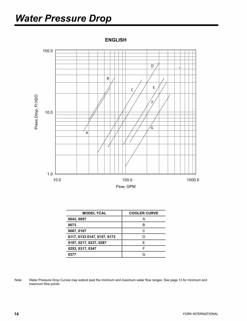
Note: Water Pressure Drop Curves may extend past the minimum and maximum water flow ranges. See page 13 for minimum and maximum flow points.
ENGLISH
MODEL YCAL COOLER CURVE0043, 0057 A0073 B0087, 0107 C0117, 0133 0147, 0157, 0173 D0197, 0217, 0237, 0287 E0253, 0317, 0347 F0377 G
���
����
�����
���� ����� ������
���������
������������������
A
B
C
D
E
F
G
YORK INTERNATIONAL14 YORK INTERNATIONAL 15
FORM 150.62-EG2
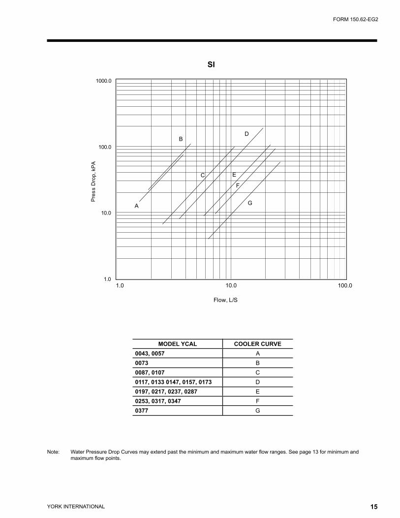
Note: Water Pressure Drop Curves may extend past the minimum and maximum water flow ranges. See page 13 for minimum and maximum flow points.
SI
���
����
�����
������
���������������
���������
��� ���� �����
�
�
�
�
�
�
�
MODEL YCAL COOLER CURVE0043, 0057 A0073 B0087, 0107 C0117, 0133 0147, 0157, 0173 D0197, 0217, 0237, 0287 E0253, 0317, 0347 F0377 G

YORK INTERNATIONAL16 YORK INTERNATIONAL 17
FORM 150.62-EG2
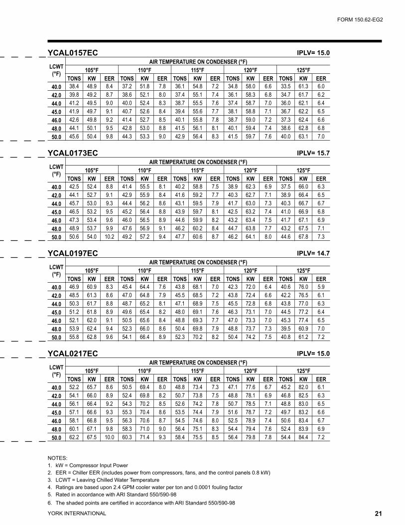
NOTES:1. kW = Compressor Input Power2. EER = Chiller EER (includes power from compressors, fans, and the control panels 0.8 kW)3. LCWT = Leaving Chilled Water Temperature4. Ratings are based upon 2.4 GPM cooler water per ton and 0.0001 fouling factor5. Rated in accordance with ARI Standard 550/590-986. The shaded points are certified in accordance with ARI Standard 550/590-98
Ratings - R-22 (English Units)YCAL0043EC IPLV= 12.9
LCWT(°F)
AIR TEMPERATURE ON CONDENSER (°F)75°F 80°F 85°F 90°F 95°F 100°F
TONS KW EER TONS KW EER TONS KW EER TONS KW EER TONS KW EER TONS KW EER40.0 11.3 8.7 11.8 11.0 9.2 11.0 10.8 9.7 10.3 10.5 10.3 9.6 10.2 10.9 9.0 10.0 11.5 8.442.0 11.8 8.8 12.2 11.4 9.2 11.4 11.2 9.7 10.7 10.9 10.3 10.0 10.6 10.9 9.3 10.4 11.5 8.744.0 12.2 8.8 12.6 11.9 9.3 11.8 11.6 9.8 11.0 11.3 10.3 10.3 11.0 10.9 9.6 10.8 11.6 9.045.0 12.4 8.8 12.8 12.1 9.3 12.0 11.8 9.8 11.2 11.5 10.4 10.5 11.2 11.0 9.8 11.0 11.6 9.146.0 12.6 8.8 13.0 12.3 9.3 12.2 12.0 9.8 11.4 11.7 10.4 10.7 11.5 11.0 10.0 11.2 11.6 9.348.0 13.1 8.9 13.5 12.8 9.3 12.6 12.4 9.9 11.8 12.1 10.4 11.0 11.9 11.0 10.3 11.6 11.7 9.650.0 13.6 8.9 13.9 13.2 9.4 13.0 12.9 9.9 12.2 12.6 10.5 11.4 12.3 11.1 10.6 12.0 11.7 9.9
YCAL0057EC IPLV= 13.5
LCWT(°F)
AIR TEMPERATURE ON CONDENSER (°F)75.0 80.0 85.0 90.0 95.0 100.0
TONS KW EER TONS KW EER TONS KW EER TONS KW EER TONS KW EER TONS KW EER40.0 15.6 12.5 12.2 15.2 13.2 11.4 14.9 14.0 10.6 14.4 14.9 9.8 14.1 15.8 9.1 13.7 16.7 8.442.0 16.1 12.6 12.6 15.8 13.3 11.7 15.4 14.1 10.9 15.0 15.0 10.1 14.6 15.9 9.4 14.2 16.8 8.744.0 16.6 12.6 12.9 16.3 13.4 12.1 15.9 14.2 11.2 15.5 15.1 10.4 15.1 16.0 9.7 14.7 16.9 8.945.0 16.9 12.7 13.1 16.6 13.4 12.3 16.2 14.3 11.4 15.8 15.1 10.6 15.4 16.0 9.8 14.9 16.9 9.146.0 17.3 12.7 13.4 16.8 13.5 12.4 16.5 14.3 11.6 16.1 15.2 10.7 15.6 16.1 9.9 15.2 17.0 9.248.0 17.9 12.8 13.7 17.4 13.6 12.7 17.0 14.4 11.9 16.6 15.2 11.0 16.2 16.1 10.2 15.7 17.1 9.550.0 18.5 12.9 14.1 18.1 13.7 13.2 17.6 14.5 12.2 17.2 15.3 11.4 16.7 16.2 10.5 16.3 17.2 9.8
YCAL0073EC IPLV= 13.7
LCWT(°F)
AIR TEMPERATURE ON CONDENSER (°F)75°F 80°F 85°F 90°F 95°F 100°F
TONS KW EER TONS KW EER TONS KW EER TONS KW EER TONS KW EER TONS KW EER40.0 19.3 15.6 12.6 18.9 16.4 11.8 18.5 17.3 11.0 18.0 18.2 10.3 17.6 19.3 9.6 17.1 20.4 8.942.0 20.0 15.7 12.9 19.6 16.5 12.1 19.1 17.4 11.4 18.7 18.3 10.6 18.2 19.4 9.9 17.7 20.5 9.144.0 20.7 15.8 13.3 20.3 16.6 12.5 19.8 17.5 11.7 19.4 18.4 10.9 18.9 19.5 10.2 18.4 20.6 9.445.0 21.1 15.9 13.5 20.6 16.7 12.7 20.2 17.6 11.9 19.7 18.5 11.1 19.2 19.5 10.3 18.7 20.6 9.646.0 21.4 15.9 13.7 21.0 16.7 12.9 20.5 17.6 12.1 20.1 18.5 11.3 19.6 19.6 10.5 19.0 20.7 9.748.0 22.2 16.0 14.1 21.7 16.8 13.3 21.2 17.7 12.4 20.8 18.7 11.6 20.2 19.7 10.8 19.7 20.8 10.050.0 23.0 16.2 14.5 22.5 17.0 13.6 22.0 17.8 12.8 21.5 18.8 11.9 20.9 19.8 11.1 20.4 20.9 10.3
YCAL0087EC IPLV= 14.8
LCWT(°F)
AIR TEMPERATURE ON CONDENSER (°F)75°F 80°F 85°F 90°F 95°F 100°F
TONS KW EER TONS KW EER TONS KW EER TONS KW EER TONS KW EER TONS KW EER40.0 24.7 18.9 13.6 24.1 20.1 12.6 23.6 21.3 11.7 23.0 22.6 10.9 22.5 24.0 10.1 21.9 25.5 9.342.0 25.6 19.1 14.0 25.0 20.2 13.0 24.4 21.5 12.1 23.9 22.8 11.2 23.3 24.1 10.4 22.7 25.6 9.644.0 26.5 19.2 14.4 25.9 20.4 13.4 25.3 21.6 12.4 24.7 22.9 11.5 24.1 24.3 10.7 23.5 25.8 9.945.0 26.9 19.3 14.6 26.3 20.4 13.6 25.7 21.7 12.6 25.2 23.0 11.7 24.6 24.4 10.8 23.9 25.8 10.046.0 27.4 19.4 14.8 26.8 20.5 13.8 26.2 21.7 12.8 25.6 23.0 11.9 25.0 24.4 11.0 24.4 25.9 10.248.0 28.3 19.5 15.2 27.7 20.7 14.2 27.1 21.9 13.2 26.5 23.2 12.2 25.9 24.6 11.3 25.2 26.1 10.550.0 29.3 19.7 15.6 28.7 20.8 14.6 28.0 22.0 13.5 27.4 23.3 12.6 26.7 24.7 11.7 26.1 26.2 10.8

YORK INTERNATIONAL16 YORK INTERNATIONAL 17
FORM 150.62-EG2
NOTES:1. kW = Compressor Input Power2. EER = Chiller EER (includes power from compressors, fans, and the control panels 0.8 kW)3. LCWT = Leaving Chilled Water Temperature4. Ratings are based upon 2.4 GPM cooler water per ton and 0.0001 fouling factor5. Rated in accordance with ARI Standard 550/590-986. The shaded points are certified in accordance with ARI Standard 550/590-98
YCAL0043EC IPLV= 12.9
LCWT(°F)
AIR TEMPERATURE ON CONDENSER (°F)105°F 110°F 115°F 120°F 125°F
TONS KW EER TONS KW EER TONS KW EER TONS KW EER TONS KW EER40.0 9.7 12.2 7.8 9.4 12.9 7.2 9.2 13.7 6.7 8.9 14.5 6.2 8.5 15.3 5.642.0 10.1 12.2 8.1 9.8 12.9 7.5 9.5 13.7 6.9 9.2 14.5 6.4 8.8 15.4 5.844.0 10.5 12.3 8.4 10.2 13.0 7.7 9.9 13.7 7.2 9.5 14.5 6.6 9.2 15.4 6.145.0 10.7 12.3 8.5 10.4 13.0 7.9 10.1 13.8 7.3 9.7 14.6 6.7 9.4 15.4 6.246.0 10.9 12.3 8.6 10.6 13.0 8.0 10.2 13.8 7.4 9.9 14.6 6.8 9.5 15.4 6.348.0 11.3 12.3 8.9 11.0 13.1 8.3 10.6 13.8 7.7 10.3 14.6 7.1 9.9 15.5 6.550.0 11.7 12.4 9.2 11.4 13.1 8.6 11.0 13.9 7.9 10.7 14.7 7.3 10.3 15.5 6.7
YCAL0057EC IPLV= 13.5
LCWT(°F)
AIR TEMPERATURE ON CONDENSER (°F)105°F 110°F 115°F 120°F 125°F
TONS KW EER TONS KW EER TONS KW EER TONS KW EER TONS KW EER40.0 13.2 17.7 7.8 12.8 18.7 7.2 12.4 19.8 6.6 12.0 20.9 6.1 11.6 22.1 5.642.0 13.7 17.8 8.0 13.3 18.8 7.4 12.9 19.9 6.8 12.4 21.0 6.3 12.0 22.2 5.844.0 14.3 17.9 8.3 13.8 18.9 7.6 13.3 20.0 7.0 12.9 21.2 6.5 12.5 22.3 5.945.0 14.6 18.0 8.4 14.0 19.0 7.7 13.8 20.1 7.2 13.1 21.2 6.6 12.7 22.4 6.046.0 14.7 18.0 8.5 14.4 19.1 7.9 13.8 20.1 7.2 13.4 21.3 6.7 12.9 22.5 6.148.0 15.3 18.1 8.8 14.9 19.2 8.1 14.4 20.3 7.5 13.9 21.4 6.9 13.4 22.6 6.350.0 15.8 18.2 9.0 15.3 19.3 8.3 14.9 20.4 7.7 14.4 21.5 7.1 13.8 22.7 6.5
YCAL0073EC IPLV= 13.7
LCWT(°F)
AIR TEMPERATURE ON CONDENSER (°F)105°F 110°F 115°F 120°F 125°F
TONS KW EER TONS KW EER TONS KW EER TONS KW EER TONS KW EER40.0 16.6 21.5 8.2 16.1 22.8 7.5 15.6 24.1 7.0 15.0 25.4 6.4 14.4 26.9 5.842.0 17.2 21.6 8.5 16.6 22.9 7.8 16.1 24.2 7.2 15.6 25.6 6.6 14.9 27.0 6.044.0 17.9 21.7 8.7 17.2 23.0 8.0 16.7 24.3 7.4 16.1 25.7 6.8 15.6 27.1 6.245.0 18.2 21.8 8.9 17.6 23.0 8.2 17.0 24.4 7.5 16.4 25.7 6.9 15.9 27.2 6.346.0 18.5 21.8 9.0 17.9 23.1 8.3 17.4 24.4 7.7 16.8 25.8 7.0 16.1 27.3 6.448.0 19.2 22.0 9.3 18.6 23.2 8.6 17.9 24.5 7.9 17.3 25.9 7.2 16.7 27.4 6.650.0 19.8 22.1 9.6 19.2 23.3 8.8 18.6 24.6 8.1 18.0 26.1 7.5 17.3 27.5 6.9
YCAL0087EC IPLV= 14.8
LCWT(°F)
AIR TEMPERATURE ON CONDENSER (°F)105°F 110°F 115°F 120°F 125°F
TONS KW EER TONS KW EER TONS KW EER TONS KW EER TONS KW EER40.0 21.3 27.0 8.6 20.7 28.6 7.9 20.1 30.4 7.3 19.4 32.2 6.7 18.7 34.1 6.142.0 22.1 27.2 8.9 21.5 28.8 8.2 20.8 30.5 7.5 20.2 32.4 6.9 19.4 34.3 6.344.0 22.9 27.3 9.1 22.3 29.0 8.4 21.6 30.7 7.7 20.9 32.5 7.1 20.2 34.4 6.545.0 23.3 27.4 9.3 22.7 29.0 8.5 22.0 30.8 7.9 21.3 32.6 7.2 20.5 34.5 6.646.0 23.7 27.5 9.4 23.1 29.1 8.7 22.4 30.9 8.0 21.6 32.7 7.3 20.9 34.6 6.748.0 24.5 27.6 9.7 23.9 29.3 8.9 23.1 31.0 8.2 22.4 32.9 7.5 21.6 34.8 6.950.0 25.4 27.8 10.0 24.7 29.4 9.2 23.9 31.2 8.4 23.2 33.0 7.8 22.4 35.0 7.1

YORK INTERNATIONAL18 YORK INTERNATIONAL 19
FORM 150.62-EG2
Ratings - R-22 (English Units)
NOTES:1. kW = Compressor Input Power2. EER = Chiller EER (includes power from compressors, fans, and the control panels 0.8 kW)3. LCWT = Leaving Chilled Water Temperature4. Ratings are based upon 2.4 GPM cooler water per ton and 0.0001 fouling factor5. Rated in accordance with ARI Standard 550/590-986. The shaded points are certified in accordance with ARI Standard 550/590-98
YCAL0107EC IPLV= 14.7
LCWT(°F)
AIR TEMPERATURE ON CONDENSER (°F)75°F 80°F 85°F 90°F 95°F 100°F
TONS KW EER TONS KW EER TONS KW EER TONS KW EER TONS KW EER TONS KW EER40.0 29.6 24.4 13.0 29.0 25.7 12.2 28.3 27.1 11.3 27.6 28.7 10.5 26.9 30.3 9.8 26.1 32.0 9.042.0 30.7 24.6 13.4 30.0 25.9 12.5 29.3 27.3 11.7 28.6 28.8 10.8 27.8 30.5 10.0 27.1 32.2 9.344.0 31.7 24.8 13.8 31.0 26.1 12.9 30.3 27.5 12.0 29.6 29.0 11.1 28.8 30.7 10.3 28.0 32.4 9.645.0 32.3 24.9 14.0 31.6 26.2 13.1 30.8 27.6 12.2 30.1 29.1 11.3 29.3 30.8 10.5 28.5 32.5 9.746.0 32.8 25.0 14.2 32.1 26.3 13.2 31.4 27.7 12.3 30.6 29.2 11.5 29.8 30.9 10.6 29.0 32.6 9.848.0 34.0 25.2 14.5 33.2 26.5 13.6 32.5 27.9 12.7 31.7 29.4 11.8 30.8 31.1 10.9 30.0 32.8 10.150.0 35.1 25.4 14.9 34.3 26.7 14.0 33.6 28.1 13.0 32.7 29.6 12.1 31.9 31.3 11.2 31.0 33.0 10.4
YCAL0117EC IPLV= 15.3
LCWT(°F)
AIR TEMPERATURE ON CONDENSER (°F)75°F 80°F 85°F 90°F 95°F 100°F
TONS KW EER TONS KW EER TONS KW EER TONS KW EER TONS KW EER TONS KW EER40.0 33.9 24.1 13.7 33.1 25.5 12.8 32.3 27.1 11.9 31.6 28.7 11.1 30.8 30.4 10.3 30.0 32.3 9.542.0 35.1 24.2 14.1 34.4 25.7 13.2 33.6 27.2 12.3 32.8 28.8 11.4 32.0 30.5 10.6 31.1 32.4 9.844.0 36.4 24.3 14.6 35.6 25.8 13.6 34.8 27.3 12.7 34.0 28.9 11.8 33.1 30.6 11.0 32.2 32.5 10.245.0 37.1 24.4 14.9 36.3 25.8 13.9 35.4 27.4 12.9 34.6 29.0 12.0 33.8 30.7 11.2 32.8 32.5 10.346.0 37.8 24.4 15.1 36.9 25.9 14.1 36.1 27.4 13.1 35.2 29.1 12.2 34.2 30.8 11.3 33.4 32.6 10.548.0 39.1 24.6 15.5 38.3 26.0 14.5 37.4 27.6 13.5 36.5 29.2 12.6 35.5 30.9 11.7 34.7 32.7 10.950.0 40.5 24.7 16.0 39.6 26.2 15.0 38.7 27.7 13.9 37.8 29.3 13.0 36.8 31.1 12.0 35.8 32.9 11.2
YCAL0133EC IPLV= 14.7
LCWT(°F)
AIR TEMPERATURE ON CONDENSER (°F)75°F 80°F 85°F 90°F 95°F 100°F
TONS KW EER TONS KW EER TONS KW EER TONS KW EER TONS KW EER TONS KW EER40.0 37.2 27.8 13.4 36.5 29.3 12.5 35.7 31.0 11.7 34.8 32.7 10.9 33.9 34.6 10.1 33.0 36.6 9.442.0 38.6 27.9 13.8 37.8 29.5 12.9 37.0 31.1 12.1 36.1 32.9 11.3 35.2 34.8 10.4 34.2 36.8 9.744.0 40.0 28.1 14.2 39.2 29.6 13.3 38.3 31.3 12.4 37.4 33.0 11.6 36.5 34.9 10.8 35.5 37.0 10.045.0 40.7 28.2 14.5 39.9 29.7 13.5 39.0 31.4 12.6 38.0 33.1 11.8 37.1 35.0 11.0 36.1 37.1 10.246.0 41.4 28.3 14.7 40.6 29.8 13.7 39.6 31.5 12.8 38.7 33.2 12.0 37.8 35.1 11.1 36.8 37.1 10.348.0 42.9 28.5 15.1 42.0 30.0 14.2 41.0 31.6 13.2 40.1 33.4 12.3 39.0 35.3 11.5 38.0 37.3 10.650.0 44.4 28.7 15.6 43.4 30.2 14.6 42.5 31.8 13.6 41.5 33.6 12.7 40.4 35.5 11.8 39.3 37.5 11.0
YCAL0147EC IPLV= 14.5
LCWT(°F)
AIR TEMPERATURE ON CONDENSER (°F)75°F 80°F 85°F 90°F 95°F 100°F
TONS KW EER TONS KW EER TONS KW EER TONS KW EER TONS KW EER TONS KW EER40.0 40.6 31.4 13.2 39.8 33.1 12.3 38.9 34.8 11.5 38.0 36.8 10.8 37.0 38.8 10.0 36.0 41.0 9.342.0 42.1 31.6 13.6 41.2 33.3 12.7 40.3 35.1 11.9 39.3 37.0 11.1 38.4 39.0 10.3 37.4 41.2 9.644.0 43.6 31.9 14.0 42.7 33.5 13.1 41.7 35.3 12.3 40.8 37.2 11.4 39.7 39.2 10.6 38.7 41.5 9.945.0 44.4 32.0 14.2 43.4 33.6 13.3 42.5 35.4 12.4 41.5 37.3 11.6 40.4 39.4 10.8 39.3 41.6 10.046.0 45.1 32.1 14.4 44.2 33.7 13.5 43.2 35.5 12.6 42.2 37.4 11.8 41.1 39.5 11.0 40.1 41.7 10.248.0 46.7 32.4 14.8 45.7 34.0 13.9 44.7 35.7 13.0 43.7 37.6 12.1 42.6 39.7 11.3 41.5 41.9 10.550.0 48.3 32.6 15.2 47.3 34.2 14.3 46.3 35.9 13.4 45.2 37.8 12.5 44.1 39.9 11.6 42.9 42.1 10.8

YORK INTERNATIONAL18 YORK INTERNATIONAL 19
FORM 150.62-EG2
NOTES:1. kW = Compressor Input Power2. EER = Chiller EER (includes power from compressors, fans, and the control panels 0.8 kW)3. LCWT = Leaving Chilled Water Temperature4. Ratings are based upon 2.4 GPM cooler water per ton and 0.0001 fouling factor5. Rated in accordance with ARI Standard 550/590-986. The shaded points are certified in accordance with ARI Standard 550/590-98
YCAL0107EC IPLV= 14.7
LCWT(°F)
AIR TEMPERATURE ON CONDENSER (°F)105°F 110°F 115°F 120°F 125°F
TONS KW EER TONS KW EER TONS KW EER TONS KW EER TONS KW EER40.0 25.3 33.8 8.3 24.5 35.7 7.6 23.6 37.7 7.0 22.8 39.9 6.4 21.8 42.1 5.842.0 26.3 34.0 8.6 25.4 35.9 7.9 24.5 38.0 7.2 23.6 40.1 6.6 22.7 42.3 6.044.0 27.2 34.2 8.8 26.3 36.2 8.1 25.4 38.2 7.4 24.5 40.4 6.8 23.6 42.6 6.245.0 27.7 34.3 8.9 26.8 36.3 8.2 25.9 38.3 7.6 25.0 40.5 6.9 24.0 42.8 6.346.0 28.2 34.4 9.1 27.3 36.4 8.4 26.4 38.5 7.7 25.4 40.6 7.0 24.4 42.9 6.448.0 29.1 34.7 9.3 28.2 36.6 8.6 27.3 38.7 7.9 26.3 40.9 7.2 25.3 43.2 6.650.0 30.1 34.9 9.6 29.2 36.8 8.8 28.3 38.9 8.1 27.3 41.1 7.4 26.3 43.4 6.8
YCAL0117EC IPLV= 15.3
LCWT(°F)
AIR TEMPERATURE ON CONDENSER (°F)105°F 110°F 115°F 120°F 125°F
TONS KW EER TONS KW EER TONS KW EER TONS KW EER TONS KW EER40.0 29.1 34.2 8.8 28.2 36.2 8.1 27.4 38.4 7.5 26.5 40.6 6.9 25.6 42.9 6.342.0 30.2 34.3 9.1 29.4 36.3 8.4 28.4 38.5 7.7 27.5 40.7 7.1 26.6 43.1 6.644.0 31.3 34.4 9.4 30.4 36.5 8.7 29.5 38.6 8.0 28.5 40.8 7.4 27.6 43.2 6.845.0 31.9 34.5 9.6 31.0 36.5 8.8 30.0 38.7 8.1 29.1 40.9 7.5 28.1 43.3 6.946.0 32.5 34.5 9.7 31.5 36.6 9.0 30.6 38.7 8.3 29.6 41.0 7.6 28.6 43.4 7.048.0 33.6 34.7 10.0 32.6 36.7 9.3 31.7 38.9 8.5 30.7 41.1 7.9 29.7 43.5 7.350.0 34.9 34.8 10.4 33.8 36.9 9.6 32.8 39.0 8.8 31.8 41.3 8.1 30.7 43.7 7.5
YCAL0133EC IPLV= 14.7
LCWT(°F)
AIR TEMPERATURE ON CONDENSER (°F)105°F 110°F 115°F 120°F 125°F
TONS KW EER TONS KW EER TONS KW EER TONS KW EER TONS KW EER40.0 32.1 38.8 8.7 31.1 41.0 8.0 30.1 43.4 7.4 29.0 45.9 6.8 27.9 48.5 6.242.0 33.3 38.9 9.0 32.3 41.2 8.3 31.2 43.6 7.6 30.2 46.1 7.0 29.0 48.7 6.444.0 34.5 39.1 9.2 33.4 41.4 8.5 32.4 43.8 7.9 31.3 46.3 7.2 30.2 49.0 6.645.0 35.1 39.2 9.4 34.0 41.5 8.7 33.0 43.9 8.0 31.9 46.4 7.4 30.7 49.1 6.746.0 35.7 39.3 9.5 34.6 41.6 8.8 33.5 44.0 8.1 32.5 46.5 7.5 31.3 49.2 6.948.0 37.0 39.5 9.8 35.8 41.7 9.1 34.8 44.2 8.4 33.6 46.7 7.7 32.5 49.4 7.150.0 38.3 39.7 10.1 37.2 41.9 9.4 35.9 44.4 8.6 34.8 46.9 8.0 33.6 49.6 7.3
YCAL0147EC IPLV= 14.5
LCWT(°F)
AIR TEMPERATURE ON CONDENSER (°F)105°F 110°F 115°F 120°F 125°F
TONS KW EER TONS KW EER TONS KW EER TONS KW EER TONS KW EER40.0 35.0 43.4 8.6 33.9 45.8 7.9 32.8 48.5 7.3 31.6 51.2 6.7 30.4 54.1 6.142.0 36.3 43.6 8.8 35.1 46.1 8.2 34.0 48.7 7.5 32.7 51.5 6.9 31.5 54.4 6.344.0 37.6 43.8 9.1 36.4 46.3 8.4 35.2 49.0 7.7 34.1 51.7 7.1 32.7 54.7 6.545.0 38.3 43.9 9.3 37.1 46.5 8.6 35.9 49.1 7.9 34.7 51.9 7.2 33.3 54.8 6.646.0 38.9 44.0 9.4 37.8 46.6 8.7 36.5 49.2 8.0 35.3 52.0 7.4 34.0 55.0 6.748.0 40.3 44.3 9.7 39.1 46.8 9.0 37.9 49.5 8.2 36.6 52.3 7.6 35.3 55.3 7.050.0 41.7 44.5 10.0 40.5 47.0 9.2 39.2 49.7 8.5 37.9 52.6 7.8 36.5 55.6 7.2

YORK INTERNATIONAL20 YORK INTERNATIONAL 21
FORM 150.62-EG2
Ratings - R-22 (English Units)
NOTES:1. kW = Compressor Input Power2. EER = Chiller EER (includes power from compressors, fans, and the control panels 0.8 kW)3. LCWT = Leaving Chilled Water Temperature4. Ratings are based upon 2.4 GPM cooler water per ton and 0.0001 fouling factor5. Rated in accordance with ARI Standard 550/590-986. The shaded points are certified in accordance with ARI Standard 550/590-98
YCAL0157EC IPLV= 15.0
LCWT(°F)
AIR TEMPERATURE ON CONDENSER (°F)75°F 80°F 85°F 90°F 95°F 100°F
TONS KW EER TONS KW EER TONS KW EER TONS KW EER TONS KW EER TONS KW EER40.0 44.5 34.9 13.2 43.4 36.9 12.3 42.6 39.0 11.5 41.6 41.2 10.6 40.5 43.7 9.9 39.5 46.2 9.142.0 46.1 35.2 13.6 45.1 37.1 12.7 44.1 39.3 11.8 43.1 41.5 11.0 42.0 43.9 10.2 40.9 46.5 9.444.0 47.6 35.4 13.9 46.7 37.4 13.0 45.6 39.5 12.1 44.6 41.8 11.3 43.5 44.2 10.5 42.3 46.8 9.745.0 48.5 35.6 14.1 47.5 37.5 13.2 46.4 39.7 12.3 45.4 41.9 11.5 44.2 44.3 10.6 43.1 46.9 9.846.0 49.4 35.7 14.3 48.3 37.7 13.4 47.2 39.8 12.5 46.1 42.1 11.6 45.0 44.5 10.8 43.8 47.1 10.048.0 51.1 36.0 14.7 50.0 38.0 13.8 48.8 40.1 12.8 47.7 42.3 11.9 46.6 44.8 11.1 45.4 47.4 10.350.0 52.8 36.3 15.1 51.7 38.3 14.1 50.5 40.4 13.2 49.4 42.6 12.3 48.1 45.1 11.4 46.6 47.6 10.5
YCAL0173EC IPLV= 15.7
LCWT(°F)
AIR TEMPERATURE ON CONDENSER (°F)75°F 80°F 85°F 90°F 95°F 100°F
TONS KW EER TONS KW EER TONS KW EER TONS KW EER TONS KW EER TONS KW EER40.0 49.1 36.9 13.9 48.0 39.1 12.9 47.0 41.5 12.0 45.9 44.0 11.1 44.8 46.6 10.3 43.7 49.5 9.542.0 50.8 37.2 14.3 49.7 39.4 13.3 48.7 41.7 12.3 47.5 44.3 11.4 46.4 46.9 10.6 45.3 49.7 9.844.0 52.6 37.4 14.7 51.5 39.7 13.7 50.3 42.0 12.7 49.2 44.5 11.8 48.1 47.2 10.9 46.9 50.0 10.145.0 53.5 37.6 14.9 52.4 39.8 13.8 51.2 42.2 12.9 50.0 44.7 11.9 48.9 47.4 11.1 47.7 50.2 10.346.0 54.4 37.7 15.1 53.3 39.9 14.0 52.1 42.3 13.1 50.8 44.8 12.1 49.8 47.5 11.2 48.5 50.3 10.448.0 56.3 38.0 15.5 55.1 40.3 14.4 53.9 42.6 13.4 52.7 45.1 12.5 51.5 47.8 11.6 50.2 50.7 10.750.0 58.2 38.4 15.9 57.0 40.6 14.8 55.7 42.9 13.8 54.5 45.4 12.8 53.2 48.1 11.9 51.9 51.0 11.0
YCAL0197EC IPLV= 14.7
LCWT(°F)
AIR TEMPERATURE ON CONDENSER (°F)75°F 80°F 85°F 90°F 95°F 100°F
TONS KW EER TONS KW EER TONS KW EER TONS KW EER TONS KW EER TONS KW EER40.0 54.9 43.6 13.1 53.6 46.0 12.2 52.4 48.7 11.3 51.1 51.5 10.5 49.6 54.4 9.7 48.3 57.6 9.042.0 56.8 43.9 13.5 55.6 46.3 12.5 54.3 49.0 11.7 52.9 51.8 10.8 51.5 54.8 10.0 50.0 57.9 9.344.0 58.9 44.2 13.8 57.5 46.7 12.9 56.2 49.3 12.0 54.8 52.1 11.2 53.3 55.1 10.3 51.9 58.3 9.645.0 59.9 44.4 14.0 58.5 46.8 13.1 57.1 49.5 12.2 55.7 52.3 11.3 54.2 55.3 10.5 52.8 58.5 9.746.0 60.9 44.5 14.2 59.4 47.0 13.3 58.1 49.6 12.4 56.7 52.4 11.5 55.2 55.4 10.6 53.7 58.6 9.848.0 63.0 44.9 14.6 61.6 47.3 13.7 60.1 50.0 12.7 58.7 52.8 11.8 57.1 55.8 10.9 55.5 59.0 10.150.0 65.2 45.2 15.0 63.7 47.7 14.0 62.2 50.3 13.1 60.7 53.1 12.1 59.1 56.2 11.3 57.4 59.4 10.4
YCAL0217EC IPLV= 15.0
LCWT(°F)
AIR TEMPERATURE ON CONDENSER (°F)75°F 80°F 85°F 90°F 95°F 100°F
TONS KW EER TONS KW EER TONS KW EER TONS KW EER TONS KW EER TONS KW EER40.0 60.6 47.4 13.4 59.5 49.9 12.6 58.1 52.6 11.7 56.7 55.6 10.9 55.3 58.7 10.1 53.8 62.1 9.442.0 63.0 47.7 13.9 61.6 50.3 13.0 60.2 53.0 12.1 58.8 55.9 11.3 57.3 59.1 10.4 55.7 62.4 9.744.0 65.2 48.1 14.3 63.8 50.6 13.3 62.2 53.3 12.4 60.9 56.3 11.6 59.3 59.4 10.8 57.7 62.8 10.045.0 66.3 48.3 14.5 64.9 50.8 13.5 63.3 53.5 12.6 61.9 56.4 11.8 60.4 59.6 10.9 58.8 63.0 10.146.0 67.5 48.5 14.7 66.1 51.0 13.7 64.6 53.7 12.8 63.0 56.6 11.9 61.4 59.8 11.1 59.8 63.1 10.348.0 69.9 48.8 15.1 68.3 51.3 14.1 66.8 54.0 13.2 65.0 56.9 12.2 63.5 60.1 11.4 61.8 63.5 10.650.0 72.3 49.2 15.5 70.7 51.7 14.5 69.1 54.4 13.5 67.4 57.3 12.6 65.6 60.5 11.7 64.0 63.9 10.9
YORK INTERNATIONAL20 YORK INTERNATIONAL 21
FORM 150.62-EG2
NOTES:1. kW = Compressor Input Power2. EER = Chiller EER (includes power from compressors, fans, and the control panels 0.8 kW)3. LCWT = Leaving Chilled Water Temperature4. Ratings are based upon 2.4 GPM cooler water per ton and 0.0001 fouling factor5. Rated in accordance with ARI Standard 550/590-986. The shaded points are certified in accordance with ARI Standard 550/590-98
YCAL0157EC IPLV= 15.0
LCWT(°F)
AIR TEMPERATURE ON CONDENSER (°F)105°F 110°F 115°F 120°F 125°F
TONS KW EER TONS KW EER TONS KW EER TONS KW EER TONS KW EER40.0 38.4 48.9 8.4 37.2 51.8 7.8 36.1 54.8 7.2 34.8 58.0 6.6 33.5 61.3 6.042.0 39.8 49.2 8.7 38.6 52.1 8.0 37.4 55.1 7.4 36.1 58.3 6.8 34.7 61.7 6.244.0 41.2 49.5 9.0 40.0 52.4 8.3 38.7 55.5 7.6 37.4 58.7 7.0 36.0 62.1 6.445.0 41.9 49.7 9.1 40.7 52.6 8.4 39.4 55.6 7.7 38.1 58.8 7.1 36.7 62.2 6.546.0 42.6 49.8 9.2 41.4 52.7 8.5 40.1 55.8 7.8 38.7 59.0 7.2 37.3 62.4 6.648.0 44.1 50.1 9.5 42.8 53.0 8.8 41.5 56.1 8.1 40.1 59.4 7.4 38.6 62.8 6.850.0 45.6 50.4 9.8 44.3 53.3 9.0 42.9 56.4 8.3 41.5 59.7 7.6 40.0 63.1 7.0
YCAL0173EC IPLV= 15.7
LCWT(°F)
AIR TEMPERATURE ON CONDENSER (°F)105°F 110°F 115°F 120°F 125°F
TONS KW EER TONS KW EER TONS KW EER TONS KW EER TONS KW EER40.0 42.5 52.4 8.8 41.4 55.5 8.1 40.2 58.8 7.5 38.9 62.3 6.9 37.5 66.0 6.342.0 44.1 52.7 9.1 42.9 55.9 8.4 41.6 59.2 7.7 40.3 62.7 7.1 38.9 66.4 6.544.0 45.7 53.0 9.3 44.4 56.2 8.6 43.1 59.5 7.9 41.7 63.0 7.3 40.3 66.7 6.745.0 46.5 53.2 9.5 45.2 56.4 8.8 43.9 59.7 8.1 42.5 63.2 7.4 41.0 66.9 6.846.0 47.3 53.4 9.6 46.0 56.5 8.9 44.6 59.9 8.2 43.2 63.4 7.5 41.7 67.1 6.948.0 48.9 53.7 9.9 47.6 56.9 9.1 46.2 60.2 8.4 44.7 63.8 7.7 43.2 67.5 7.150.0 50.6 54.0 10.2 49.2 57.2 9.4 47.7 60.6 8.7 46.2 64.1 8.0 44.6 67.8 7.3
YCAL0197EC IPLV= 14.7
LCWT(°F)
AIR TEMPERATURE ON CONDENSER (°F)105°F 110°F 115°F 120°F 125°F
TONS KW EER TONS KW EER TONS KW EER TONS KW EER TONS KW EER40.0 46.9 60.9 8.3 45.4 64.4 7.6 43.8 68.1 7.0 42.3 72.0 6.4 40.6 76.0 5.942.0 48.5 61.3 8.6 47.0 64.8 7.9 45.5 68.5 7.2 43.8 72.4 6.6 42.2 76.5 6.144.0 50.3 61.7 8.8 48.7 65.2 8.1 47.1 68.9 7.5 45.5 72.8 6.8 43.8 77.0 6.345.0 51.2 61.8 8.9 49.6 65.4 8.2 48.0 69.1 7.6 46.3 73.1 7.0 44.5 77.2 6.446.0 52.1 62.0 9.1 50.5 65.6 8.4 48.8 69.3 7.7 47.0 73.3 7.0 45.3 77.4 6.548.0 53.9 62.4 9.4 52.3 66.0 8.6 50.4 69.8 7.9 48.8 73.7 7.3 39.5 60.9 7.050.0 55.8 62.8 9.6 54.1 66.4 8.9 52.3 70.2 8.2 50.4 74.2 7.5 40.8 61.2 7.2
YCAL0217EC IPLV= 15.0
LCWT(°F)
AIR TEMPERATURE ON CONDENSER (°F)105°F 110°F 115°F 120°F 125°F
TONS KW EER TONS KW EER TONS KW EER TONS KW EER TONS KW EER40.0 52.2 65.7 8.6 50.5 69.4 8.0 48.8 73.4 7.3 47.1 77.6 6.7 45.2 82.0 6.142.0 54.1 66.0 8.9 52.4 69.8 8.2 50.7 73.8 7.5 48.8 78.1 6.9 46.8 82.5 6.344.0 56.1 66.4 9.2 54.3 70.2 8.5 52.6 74.2 7.8 50.7 78.5 7.1 48.8 83.0 6.545.0 57.1 66.6 9.3 55.3 70.4 8.6 53.5 74.4 7.9 51.6 78.7 7.2 49.7 83.2 6.646.0 58.1 66.8 9.5 56.3 70.6 8.7 54.5 74.6 8.0 52.5 78.9 7.4 50.6 83.4 6.748.0 60.1 67.1 9.8 58.3 71.0 9.0 56.4 75.1 8.3 54.4 79.4 7.6 52.4 83.9 6.950.0 62.2 67.5 10.0 60.3 71.4 9.3 58.4 75.5 8.5 56.4 79.8 7.8 54.4 84.4 7.2

YORK INTERNATIONAL22 YORK INTERNATIONAL 23
FORM 150.62-EG2
YCAL0237EC IPLV= 15.2
LCWT(°F)
AIR TEMPERATURE ON CONDENSER (°F)75°F 80°F 85°F 90°F 95°F 100°F
TONS KW EER TONS KW EER TONS KW EER TONS KW EER TONS KW EER TONS KW EER40.0 66.4 52.9 13.4 64.9 55.9 12.4 63.5 59.1 11.5 62.0 62.6 10.7 60.5 66.3 9.9 58.8 70.2 9.242.0 68.8 53.3 13.7 67.3 56.3 12.8 65.7 59.6 11.9 64.2 63.0 11.0 62.6 66.8 10.2 61.0 70.7 9.444.0 71.2 53.7 14.1 69.7 56.8 13.1 68.1 60.0 12.2 66.4 63.5 11.3 64.8 67.2 10.5 63.1 71.2 9.745.0 72.4 54.0 14.3 70.9 57.0 13.3 69.2 60.2 12.4 67.5 63.7 11.5 65.9 67.4 10.7 64.2 71.4 9.846.0 73.6 54.2 14.5 72.1 57.2 13.5 70.4 60.5 12.6 68.8 63.9 11.7 67.1 67.7 10.8 65.3 71.6 10.048.0 76.2 54.6 14.9 74.5 57.7 13.9 72.8 60.9 12.9 71.1 64.4 12.0 69.3 68.1 11.1 67.5 72.1 10.350.0 78.7 55.1 15.3 77.0 58.1 14.2 75.3 61.4 13.2 73.5 64.9 12.3 71.6 68.6 11.4 69.8 72.6 10.5
YCAL0253EC IPLV=15.7
LCWT(°F)
AIR TEMPERATURE ON CONDENSER (°F)75°F 80°F 85°F 90°F 95°F 100°F
TONS KW EER TONS KW EER TONS KW EER TONS KW EER TONS KW EER TONS KW EER40.0 72.4 58.5 13.3 70.9 62.1 12.4 68.9 65.7 11.4 67.7 69.8 10.6 66.0 74.1 9.8 64.2 78.6 9.042.0 75.0 59.0 13.7 73.4 62.6 12.7 71.8 66.4 11.8 70.0 70.4 10.9 68.3 74.6 10.1 66.5 79.2 9.344.0 77.7 59.6 14.0 75.9 63.1 13.0 74.3 66.9 12.1 72.5 70.9 11.2 70.7 75.2 10.3 68.8 79.8 9.545.0 79.0 59.8 14.2 77.2 63.4 13.2 75.5 67.2 12.2 73.7 71.2 11.3 71.9 75.5 10.5 70.0 80.1 9.746.0 80.3 60.1 14.4 78.6 63.7 13.4 76.8 67.5 12.4 75.0 71.5 11.5 73.1 75.8 10.6 71.2 80.3 9.848.0 83.0 60.7 14.8 81.2 64.2 13.7 79.3 68.1 12.7 77.5 72.1 11.8 75.6 76.4 10.9 73.6 81.0 10.150.0 85.8 61.2 15.1 83.8 64.8 14.1 82.0 68.6 13.0 80.0 72.7 12.1 78.0 77.0 11.2 76.0 81.6 10.3
YCAL0287EC IPLV=15.0
LCWT(°F)
AIR TEMPERATURE ON CONDENSER (°F)75°F 80°F 85°F 90°F 95°F 100°F
TONS KW EER TONS KW EER TONS KW EER TONS KW EER TONS KW EER TONS KW EER40.0 81.2 70.7 12.7 79.4 74.6 11.8 77.5 78.7 10.9 75.6 83.2 10.1 73.6 88.0 9.4 71.5 93.1 8.642.0 84.0 71.4 13.0 82.1 75.3 12.1 80.2 79.5 11.2 78.2 84.1 10.4 76.2 88.9 9.6 74.1 94.0 8.944.0 86.8 72.2 13.3 84.9 76.2 12.4 82.9 80.4 11.5 80.9 84.9 10.6 78.8 89.8 9.8 76.6 95.0 9.145.0 88.3 72.6 13.4 86.3 76.6 12.5 84.3 80.8 11.6 82.2 85.4 10.8 80.1 90.3 10.0 77.9 95.5 9.246.0 89.7 73.0 13.6 87.7 77.0 12.6 85.7 81.2 11.8 83.6 85.8 10.9 81.5 90.7 10.1 79.3 95.9 9.348.0 92.7 73.8 13.9 90.6 77.8 12.9 88.6 82.1 12.0 86.4 86.7 11.1 84.2 91.7 10.3 81.9 97.0 9.550.0 95.7 74.7 14.2 93.6 78.7 13.2 91.5 83.0 12.3 89.3 87.7 11.4 87.0 92.6 10.6 84.6 98.0 9.7
NOTES:1. kW = Compressor Input Power2. EER = Chiller EER (includes power from compressors, fans, and the control panels 0.8 kW)3. LCWT = Leaving Chilled Water Temperature4. Ratings are based upon 2.4 GPM cooler water per ton and 0.0001 fouling factor5. Rated in accordance with ARI Standard 550/590-986. The shaded points are certified in accordance with ARI Standard 550/590-98
Ratings - R-22 (English Units)

YORK INTERNATIONAL22 YORK INTERNATIONAL 23
FORM 150.62-EG2
YCAL0237EC IPLV= 15.2
LCWT(°F)
AIR TEMPERATURE ON CONDENSER (°F)105°F 110°F 115°F 120°F 125°F
TONS KW EER TONS KW EER TONS KW EER TONS KW EER TONS KW EER40.0 57.2 74.4 8.5 55.4 78.8 7.8 53.6 83.4 7.1 51.7 88.2 6.5 49.6 93.2 5.942.0 59.2 74.9 8.7 57.4 79.3 8.0 55.5 83.9 7.3 53.6 88.8 6.7 51.5 93.9 6.144.0 61.3 75.3 9.0 59.5 79.8 8.2 57.5 84.4 7.6 55.5 89.3 6.9 53.4 94.5 6.345.0 62.4 75.6 9.1 60.5 80.0 8.4 58.5 84.7 7.7 56.5 89.6 7.0 45.5 74.1 6.846.0 63.5 75.8 9.2 61.6 80.3 8.5 59.6 85.0 7.8 57.5 89.9 7.1 46.4 74.3 6.948.0 65.6 76.3 9.5 63.7 80.8 8.7 61.6 85.5 8.0 59.5 90.5 7.3 48.0 74.7 7.150.0 67.8 76.8 9.7 65.8 81.3 9.0 63.7 86.1 8.2 61.5 91.1 7.5 49.7 75.1 7.3
YCAL0253EC IPLV=15.7
LCWT(°F)
AIR TEMPERATURE ON CONDENSER (°F)105°F 110°F 115°F 120°F 125°F
TONS KW EER TONS KW EER TONS KW EER TONS KW EER TONS KW EER40.0 62.4 83.3 8.3 60.5 88.3 7.6 58.6 93.5 7.0 56.4 99.0 6.4 54.4 104.7 5.842.0 64.6 83.9 8.5 62.7 88.9 7.9 60.7 94.2 7.2 58.6 99.7 6.6 56.2 105.5 6.044.0 66.9 84.5 8.8 64.9 89.6 8.1 62.8 94.9 7.4 60.6 100.4 6.8 40.8 64.8 6.845.0 68.0 84.8 8.9 66.0 89.9 8.2 63.8 95.2 7.5 61.7 100.8 6.9 41.6 65.0 6.946.0 69.2 85.1 9.0 67.1 90.2 8.3 65.0 95.5 7.6 62.7 101.1 7.0 42.3 65.2 7.148.0 71.5 85.8 9.3 69.4 90.9 8.5 67.2 96.2 7.8 64.8 101.8 7.2 43.8 65.5 7.350.0 73.9 86.4 9.5 71.7 91.5 8.7 69.4 96.9 8.0 66.9 102.5 7.3 45.3 65.8 7.5
YCAL0287EC IPLV=15.0
LCWT(°F)
AIR TEMPERATURE ON CONDENSER (°F)105°F 110°F 115°F 120°F 125°F
TONS KW EER TONS KW EER TONS KW EER TONS KW EER TONS KW EER40.0 69.3 98.6 7.9 66.9 104.4 7.3 64.4 110.6 6.6 61.8 117.2 6.0 50.6 94.7 6.042.0 71.8 99.6 8.1 69.4 105.4 7.5 66.9 111.7 6.8 54.7 90.1 6.8 39.1 66.7 6.444.0 74.3 100.5 8.4 71.9 106.5 7.7 69.3 112.8 7.0 56.7 90.9 7.0 40.7 67.2 6.645.0 75.6 101.0 8.5 73.1 107.0 7.7 70.6 113.3 7.1 57.8 91.3 7.1 41.4 67.4 6.746.0 76.9 101.6 8.6 74.4 107.5 7.8 71.8 113.9 7.2 58.8 91.7 7.2 42.2 67.7 6.948.0 79.5 102.6 8.8 77.0 108.6 8.0 74.4 115.0 7.4 61.0 92.4 7.4 43.8 68.2 7.150.0 82.2 103.7 9.0 79.7 109.7 8.2 77.0 116.1 7.5 63.1 93.2 7.6 45.4 68.6 7.3
NOTES:1. kW = Compressor Input Power2. EER = Chiller EER (includes power from compressors, fans, and the control panels 0.8 kW)3. LCWT = Leaving Chilled Water Temperature4. Ratings are based upon 2.4 GPM cooler water per ton and 0.0001 fouling factor5. Rated in accordance with ARI Standard 550/590-986. The shaded points are certified in accordance with ARI Standard 550/590-98

YORK INTERNATIONAL24 YORK INTERNATIONAL 25
FORM 150.62-EG2
Ratings - R-22 (English Units)
NOTES:1. kW = Compressor Input Power2. EER = Chiller EER (includes power from compressors, fans, and the control panels 0.8 kW)3. LCWT = Leaving Chilled Water Temperature4. Ratings are based upon 2.4 GPM cooler water per ton and 0.0001 fouling factor5. Rated in accordance with ARI Standard 550/590-986. The shaded points are certified in accordance with ARI Standard 550/590-98
YCAL0317EC IPLV= 14.3
LCWT(°F)
AIR TEMPERATURE ON CONDENSER (°F)75°F 80°F 85°F 90°F 95°F 100°F
TONS KW EER TONS KW EER TONS KW EER TONS KW EER TONS KW EER TONS KW EER40.0 92.5 76.8 12.9 90.5 81.0 12.0 88.5 85.5 11.2 86.4 90.4 10.4 84.2 95.5 9.6 81.9 101.1 8.942.0 95.7 77.6 13.2 93.7 81.8 12.3 91.6 86.3 11.5 89.4 91.1 10.7 87.2 96.3 9.9 84.8 101.9 9.144.0 99.0 78.3 13.5 96.9 82.5 12.6 94.7 87.1 11.8 92.5 91.9 11.0 90.2 97.1 10.2 87.8 102.7 9.445.0 100.7 78.7 13.7 98.5 82.9 12.8 96.3 87.4 11.9 94.1 92.3 11.1 91.8 97.6 10.3 89.3 103.2 9.546.0 102.4 79.1 13.9 100.2 83.3 13.0 98.0 87.8 12.1 95.7 92.7 11.2 93.3 98.0 10.4 90.9 103.6 9.648.0 105.9 79.9 14.2 103.6 84.1 13.3 101.3 88.6 12.4 99.0 93.5 11.5 96.5 98.8 10.7 94.0 104.5 9.950.0 109.4 80.7 14.6 107.1 84.9 13.6 104.7 89.5 12.7 102.3 94.4 11.8 99.8 99.7 11.0 97.2 105.4 10.2
YCAL0347EC IPLV= 14.5
LCWT(°F)
AIR TEMPERATURE ON CONDENSER (°F)75°F 80°F 85°F 90°F 95°F 100°F
TONS KW EER TONS KW EER TONS KW EER TONS KW EER TONS KW EER TONS KW EER40.0 99.7 83.7 12.8 97.5 88.4 12.0 95.2 93.4 11.1 92.9 98.8 10.3 90.6 104.5 9.5 88.1 110.7 8.842.0 103.2 84.6 13.2 100.9 89.3 12.3 98.5 94.3 11.4 96.2 99.7 10.6 93.7 105.5 9.8 91.2 111.7 9.044.0 106.7 85.5 13.5 104.3 90.2 12.6 101.9 95.3 11.7 99.5 100.7 10.8 97.0 106.5 10.0 94.4 112.8 9.345.0 108.5 86.0 13.6 106.0 90.7 12.7 103.6 95.8 11.8 101.1 101.2 11.0 98.6 107.1 10.2 96.0 113.3 9.446.0 110.3 86.4 13.8 107.8 91.2 12.9 105.4 96.3 12.0 102.8 101.7 11.1 100.3 107.6 10.3 97.6 113.9 9.548.0 114.0 87.3 14.1 111.4 92.1 13.2 108.9 97.2 12.2 106.3 102.8 11.4 103.6 108.7 10.5 100.9 115.0 9.750.0 117.7 88.3 14.5 115.1 93.1 13.5 112.5 98.3 12.5 109.8 103.8 11.6 107.1 109.8 10.8 104.3 116.1 10.0
YCAL0377EC IPLV= 14.7
LCWT(°F)
AIR TEMPERATURE ON CONDENSER (°F)75°F 80°F 85°F 90°F 95°F 100°F
TONS KW EER TONS KW EER TONS KW EER TONS KW EER TONS KW EER TONS KW EER40.0 108.4 91.0 12.9 105.9 96.1 12.0 103.4 101.5 11.2 100.9 107.3 10.4 98.3 113.4 9.6 95.7 120.0 8.942.0 112.1 92.0 13.3 109.5 97.1 12.3 107.0 102.6 11.5 104.4 108.4 10.6 101.7 114.6 9.8 99.0 121.2 9.144.0 115.9 93.0 13.6 113.3 98.2 12.6 110.6 103.7 11.7 108.0 109.5 10.9 105.2 115.8 10.1 102.5 122.4 9.345.0 117.8 93.5 13.7 115.2 98.7 12.8 112.5 104.2 11.9 109.8 110.1 11.0 107.0 116.4 10.2 104.2 123.1 9.446.0 119.8 94.1 13.9 117.1 99.2 12.9 114.4 104.7 12.0 111.6 110.7 11.2 108.8 117.0 10.3 105.9 123.7 9.548.0 123.8 95.1 14.2 121.0 100.3 13.2 118.2 105.9 12.3 115.3 111.9 11.4 112.4 118.3 10.6 109.5 125.0 9.850.0 127.9 96.1 14.5 125.0 101.4 13.5 122.1 107.1 12.6 119.1 113.2 11.7 116.2 119.5 10.8 113.2 126.3 10.0
YORK INTERNATIONAL24 YORK INTERNATIONAL 25
FORM 150.62-EG2
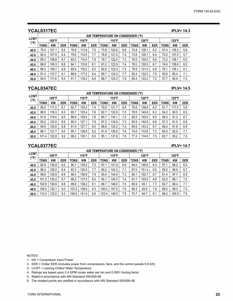
NOTES:1. kW = Compressor Input Power2. EER = Chiller EER (includes power from compressors, fans, and the control panels 0.8 kW)3. LCWT = Leaving Chilled Water Temperature4. Ratings are based upon 2.4 GPM cooler water per ton and 0.0001 fouling factor5. Rated in accordance with ARI Standard 550/590-986. The shaded points are certified in accordance with ARI Standard 550/590-98
YCAL0317EC IPLV= 14.3
LCWT(°F)
AIR TEMPERATURE ON CONDENSER (°F)105°F 110°F 115°F 120°F 125°F
TONS KW EER TONS KW EER TONS KW EER TONS KW EER TONS KW EER40.0 79.4 107.1 8.2 76.8 113.6 7.5 73.8 120.6 6.8 70.8 128.1 6.2 67.4 136.2 5.642.0 82.4 107.9 8.4 79.6 114.5 7.7 76.8 121.5 7.0 73.6 129.1 6.4 70.0 137.0 5.744.0 85.3 108.8 8.7 82.5 115.4 7.9 79.7 122.4 7.3 76.5 130.0 6.6 73.2 138.1 6.045.0 86.8 109.3 8.8 84.1 115.8 8.1 81.2 122.9 7.4 78.0 130.5 6.7 74.6 138.6 6.046.0 88.3 109.7 8.9 85.6 116.2 8.2 82.6 123.3 7.5 79.5 131.0 6.8 76.1 139.1 6.148.0 91.4 110.7 9.1 88.6 117.2 8.4 85.7 124.3 7.7 82.4 132.0 7.0 55.9 85.4 7.150.0 94.5 111.6 9.4 91.7 118.2 8.6 88.7 125.3 7.9 85.5 133.0 7.2 57.7 85.9 7.3
YCAL0347EC IPLV= 14.5
LCWT(°F)
AIR TEMPERATURE ON CONDENSER (°F)105°F 110°F 115°F 120°F 125°F
TONS KW EER TONS KW EER TONS KW EER TONS KW EER TONS KW EER40.0 85.5 117.2 8.1 82.7 124.2 7.4 79.8 131.7 6.8 76.6 139.6 6.2 61.7 117.0 5.942.0 88.5 118.3 8.3 85.7 125.4 7.6 82.7 132.9 7.0 79.5 140.8 6.3 54.2 90.5 6.544.0 91.6 119.4 8.5 88.8 126.5 7.8 85.7 134.1 7.2 82.5 142.0 6.5 56.3 91.2 6.745.0 93.2 120.0 8.6 90.3 127.1 7.9 87.2 134.6 7.3 83.9 142.6 6.6 57.3 91.5 6.846.0 94.8 120.6 8.8 91.9 127.7 8.0 88.8 135.3 7.4 85.5 143.3 6.7 58.4 91.8 6.948.0 98.1 121.7 9.0 95.1 128.9 8.2 91.9 136.5 7.6 74.6 113.8 7.3 60.5 92.5 7.150.0 101.4 122.9 9.2 98.3 130.1 8.5 95.1 137.8 7.8 77.3 114.8 7.5 62.7 93.2 7.3
YCAL0377EC IPLV= 14.7
LCWT(°F)
AIR TEMPERATURE ON CONDENSER (°F)105°F 110°F 115°F 120°F 125°F
TONS KW EER TONS KW EER TONS KW EER TONS KW EER TONS KW EER40.0 92.9 126.9 8.2 90.1 134.2 7.5 87.1 141.9 6.9 84.0 149.9 6.3 57.1 96.2 6.542.0 96.2 128.2 8.4 93.3 135.5 7.7 90.2 143.3 7.1 87.0 151.4 6.5 59.2 96.9 6.744.0 99.6 129.5 8.6 96.5 136.9 7.9 93.4 144.6 7.3 90.1 152.7 6.7 61.4 97.7 6.945.0 101.2 130.2 8.7 98.2 137.5 8.0 95.1 145.3 7.4 91.7 153.5 6.8 62.5 98.1 7.046.0 102.9 130.8 8.8 99.9 138.2 8.1 96.7 146.0 7.5 65.9 93.1 7.7 63.7 98.4 7.148.0 106.5 132.1 9.0 103.3 139.6 8.3 100.0 147.5 7.6 68.3 93.9 7.9 66.0 99.3 7.350.0 110.0 133.5 9.2 106.8 141.0 8.5 103.4 149.0 7.8 70.7 94.7 8.1 68.2 100.0 7.5

YORK INTERNATIONAL26 YORK INTERNATIONAL 27
FORM 150.62-EG2
Ratings - R-22 (SI Units)
NOTES:1. kWo = Unit kW Cooling Capacity Output2. kWi = Compressor kW Input3. COP = Coefficient of Performance (Based upon compressor and fan input kW)4. LCWT = Leaving Chilled Water Temperature5. Ratings based upon 0.15L/s cooler water per kW
YCAL0043EC COP = 3.79
LCWT(°C)
AIR TEMPERATURE ON - CONDENSER (C)25°C 30°C 35°C 40°C 45°C 50°C
kWo kWi COP kWo kWi COP kWo kWi COP kWo kWi COP kWo kWi COP kWo kWi COP5.0 40.1 8.9 3.4 38.3 9.8 3.0 36.7 10.9 2.7 35.0 12.1 2.4 33.3 13.4 2.1 31.2 14.8 1.86.0 41.5 9.0 3.5 39.7 9.9 3.1 37.9 10.9 2.8 36.2 12.1 2.4 34.4 13.4 2.1 32.3 14.9 1.87.0 42.9 9.0 3.6 41.0 9.9 3.2 39.2 10.9 2.9 37.4 12.1 2.5 35.5 13.4 2.2 33.4 14.9 1.98.0 44.3 9.0 3.8 42.3 9.9 3.3 40.6 11.0 3.0 38.7 12.2 2.6 36.8 13.5 2.3 34.6 14.9 2.09.0 45.7 9.1 3.9 43.7 10.0 3.4 41.8 11.0 3.0 40.0 12.2 2.7 38.0 13.5 2.3 35.7 15.0 2.0
10.0 47.2 9.1 4.0 45.1 10.0 3.5 43.2 11.1 3.1 41.3 12.3 2.7 39.2 13.6 2.4 36.9 15.0 2.111.0 48.7 9.2 4.1 46.6 10.1 3.6 44.6 11.1 3.2 42.6 12.3 2.8 40.5 13.6 2.5 38.1 15.1 2.1
YCAL0057EC COP = 3.96
LCWT(°C)
AIR TEMPERATURE ON - CONDENSER (C)25°C 30°C 35°C 40°C 45°C 50°C
kWo kWi COP kWo kWi COP kWo kWi COP kWo kWi COP kWo kWi COP kWo kWi COP5.0 55.2 12.8 3.5 52.8 14.2 3.1 50.3 15.8 2.7 47.7 17.5 2.4 45.1 19.4 2.0 42.3 21.4 1.86.0 57.0 12.9 3.6 54.5 14.3 3.2 52.0 15.9 2.8 49.3 17.6 2.4 46.6 19.5 2.1 43.8 21.5 1.87.0 58.5 13.0 3.7 56.3 14.4 3.3 53.8 16.0 2.9 51.2 17.7 2.5 48.1 19.6 2.2 45.2 21.7 1.98.0 60.3 13.0 3.8 58.0 14.5 3.4 55.4 16.1 2.9 52.5 17.8 2.6 49.6 19.7 2.2 46.7 21.8 1.99.0 62.1 13.1 3.9 59.9 14.6 3.5 57.1 16.2 3.0 54.3 17.9 2.6 51.4 19.8 2.3 48.2 21.9 2.0
10.0 64.5 13.2 4.0 61.3 14.6 3.5 58.8 16.2 3.1 55.9 18.0 2.7 53.1 19.9 2.3 49.7 22.0 2.011.0 66.4 13.3 4.1 63.2 14.7 3.6 60.6 16.3 3.2 57.6 18.1 2.8 54.6 20.0 2.4 51.5 22.1 2.1
YCAL0073EC COP = 4.03
LCWT(°C)
AIR TEMPERATURE ON - CONDENSER (C)25°C 30°C 35°C 40°C 45°C 50°C
kWo kWi COP kWo kWi COP kWo kWi COP kWo kWi COP kWo kWi COP kWo kWi COP5.0 68.4 16.0 3.6 65.8 17.5 3.2 62.9 19.3 2.9 59.8 21.3 2.5 56.4 23.6 2.1 52.8 26.1 1.86.0 70.6 16.1 3.7 67.9 17.6 3.3 65.0 19.4 2.9 61.8 21.4 2.6 58.4 23.7 2.2 54.8 26.2 1.97.0 72.9 16.2 3.9 70.1 17.7 3.4 67.1 19.5 3.0 63.8 21.5 2.6 60.1 23.8 2.3 56.6 26.3 1.98.0 75.2 16.3 4.0 72.3 17.8 3.5 69.2 19.6 3.1 65.9 21.6 2.7 62.0 23.9 2.3 58.5 26.4 2.09.0 77.6 16.4 4.1 74.6 17.9 3.6 71.4 19.7 3.2 68.0 21.7 2.8 64.3 24.0 2.4 60.4 26.5 2.1
10.0 80.0 16.5 4.2 76.9 18.0 3.7 73.6 19.8 3.3 70.1 21.8 2.9 66.4 24.1 2.5 62.0 26.6 2.111.0 82.5 16.6 4.3 79.3 18.1 3.8 75.9 19.9 3.4 72.3 21.9 2.9 68.5 24.2 2.5 63.9 26.7 2.2
YCAL0087EC COP = 4.35
LCWT(°C)
AIR TEMPERATURE ON - CONDENSER (C)25°C 30°C 35°C 40°C 45°C 50°C
kWo kWi COP kWo kWi COP kWo kWi COP kWo kWi COP kWo kWi COP kWo kWi COP5.0 87.5 19.5 3.9 84.1 21.6 3.4 80.5 24.1 3.0 76.8 26.8 2.6 72.9 29.7 2.2 68.7 33.0 1.96.0 90.3 19.6 4.0 86.7 21.8 3.5 83.1 24.2 3.1 79.3 26.9 2.7 75.3 29.9 2.3 71.0 33.2 2.07.0 93.2 19.7 4.1 89.5 21.9 3.6 85.8 24.3 3.2 81.9 27.0 2.7 77.7 30.0 2.4 73.2 33.3 2.08.0 96.1 19.8 4.2 92.3 22.0 3.7 88.5 24.5 3.2 84.4 27.2 2.8 80.2 30.2 2.4 75.6 33.5 2.19.0 99.1 20.0 4.4 95.2 22.2 3.8 91.2 24.6 3.3 87.1 27.3 2.9 82.7 30.3 2.5 77.9 33.6 2.1
10.0 102.1 20.1 4.5 98.2 22.3 3.9 94.0 24.7 3.4 89.7 27.5 3.0 85.2 30.5 2.6 80.4 33.8 2.211.0 105.3 20.3 4.6 101.1 22.4 4.0 96.9 24.9 3.5 92.5 27.6 3.0 87.8 30.6 2.6 82.8 34.0 2.3

YORK INTERNATIONAL26 YORK INTERNATIONAL 27
FORM 150.62-EG2
NOTES:1. kWo = Unit kW Cooling Capacity Output2. kWi = Compressor kW Input3. COP = Coefficient of Performance (Based upon compressor and fan input kW)4. LCWT = Leaving Chilled Water Temperature5. Ratings based upon 0.15L/s cooler water per kW
YCAL0107EC COP = 4.32
LCWT(°C)
AIR TEMPERATURE ON - CONDENSER (C)25°C 30°C 35°C 40°C 45°C 50°C
kWo kWi COP kWo kWi COP kWo kWi COP kWo kWi COP kWo kWi COP kWo kWi COP5.0 105.0 25.0 3.8 100.8 27.5 3.3 96.2 30.4 2.9 91.2 33.5 2.5 85.9 37.0 2.2 80.3 40.9 1.86.0 108.4 25.2 3.9 103.9 27.7 3.4 99.3 30.5 3.0 94.2 33.7 2.6 88.8 37.2 2.2 83.0 41.1 1.97.0 111.7 25.4 4.0 107.2 27.9 3.5 102.4 30.7 3.1 97.2 33.9 2.7 91.7 37.4 2.3 85.8 41.3 1.98.0 115.2 25.6 4.1 110.6 28.0 3.6 105.6 30.9 3.1 100.3 34.1 2.7 94.6 37.7 2.3 88.6 41.6 2.09.0 118.8 25.8 4.2 114.0 28.2 3.7 108.8 31.1 3.2 103.4 34.3 2.8 97.7 37.9 2.4 91.5 41.8 2.1
10.0 122.4 25.9 4.3 117.4 28.4 3.8 112.1 31.3 3.3 106.6 34.5 2.9 100.7 38.1 2.5 94.5 42.0 2.111.0 126.1 26.1 4.4 120.9 28.6 3.9 115.5 31.5 3.4 109.8 34.7 2.9 103.8 38.3 2.5 97.5 42.3 2.2
YCAL0117EC COP = 4.47
LCWT(°C)
AIR TEMPERATURE ON - CONDENSER (C)25°C 30°C 35°C 40°C 45°C 50°C
kWo kWi COP kWo kWi COP kWo kWi COP kWo kWi COP kWo kWi COP kWo kWi COP5.0 120.4 24.7 4.0 115.5 27.4 3.5 110.3 30.5 3.1 104.9 33.9 2.7 99.4 37.5 2.3 93.7 41.6 2.06.0 124.2 24.8 4.1 119.3 27.6 3.6 114.0 30.6 3.2 108.5 34.0 2.7 102.9 37.7 2.4 97.0 41.7 2.17.0 128.4 24.9 4.2 123.1 27.7 3.7 117.6 30.7 3.2 112.1 34.1 2.8 106.1 37.8 2.5 100.1 41.8 2.18.0 132.6 25.0 4.3 127.2 27.8 3.8 121.7 30.8 3.3 115.6 34.2 2.9 109.6 37.9 2.5 103.6 42.0 2.29.0 136.8 25.2 4.5 131.2 27.9 3.9 125.3 30.9 3.4 119.5 34.3 3.0 113.2 38.0 2.6 106.8 42.1 2.2
10.0 141.1 25.3 4.6 135.5 28.0 4.0 129.4 31.1 3.5 123.3 34.4 3.1 116.7 38.1 2.7 110.3 42.2 2.311.0 145.5 25.4 4.7 139.6 28.1 4.1 133.5 31.2 3.6 127.0 34.6 3.2 120.6 38.3 2.8 113.7 42.4 2.4
YCAL0133EC COP = 4.31
LCWT(°C)
AIR TEMPERATURE ON - CONDENSER (C)25°C 30°C 35°C 40°C 45°C 50°C
kWo kWi COP kWo kWi COP kWo kWi COP kWo kWi COP kWo kWi COP kWo kWi COP5.0 132.3 28.4 3.9 127.1 31.4 3.4 121.4 34.7 3.0 115.6 38.4 2.6 109.4 42.5 2.3 102.5 47.0 2.06.0 136.6 28.6 4.0 131.1 31.5 3.5 125.4 34.8 3.1 119.3 38.6 2.7 113.0 42.7 2.3 106.1 47.2 2.07.0 140.9 28.7 4.1 135.3 31.7 3.6 129.6 35.0 3.2 123.2 38.7 2.8 116.6 42.9 2.4 109.7 47.4 2.18.0 145.5 28.9 4.2 139.7 31.8 3.7 133.6 35.1 3.3 127.3 38.9 2.9 120.3 43.0 2.5 113.4 47.6 2.19.0 150.1 29.1 4.3 144.1 32.0 3.8 137.8 35.3 3.4 131.3 39.0 2.9 124.3 43.2 2.6 117.0 47.8 2.2
10.0 154.8 29.3 4.4 148.6 32.2 3.9 142.0 35.5 3.5 135.4 39.2 3.0 128.4 43.4 2.6 120.8 48.0 2.311.0 159.6 29.4 4.6 153.1 32.3 4.0 146.5 35.6 3.6 139.5 39.4 3.1 132.3 43.6 2.7 124.6 48.2 2.3
YCAL0147EC COP = 4.26
LCWT(°C)
AIR TEMPERATURE ON - CONDENSER (C)25°C 30°C 35°C 40°C 45°C 50°C
kWo kWi COP kWo kWi COP kWo kWi COP kWo kWi COP kWo kWi COP kWo kWi COP5.0 144.2 32.2 3.8 138.6 35.3 3.4 132.5 38.9 3.0 126.0 43.0 2.6 119.1 47.5 2.2 111.5 52.5 1.96.0 148.9 32.4 3.9 143.1 35.5 3.5 136.8 39.1 3.1 130.2 43.2 2.7 122.9 47.7 2.3 115.2 52.7 2.07.0 153.6 32.6 4.0 147.6 35.7 3.6 141.2 39.3 3.1 134.4 43.4 2.7 127.0 48.0 2.4 119.4 53.0 2.08.0 158.5 32.8 4.1 152.3 35.9 3.7 145.7 39.5 3.2 138.7 43.6 2.8 131.2 48.2 2.4 123.3 53.2 2.19.0 163.5 33.0 4.2 157.1 36.1 3.8 150.3 39.7 3.3 143.0 43.8 2.9 135.4 48.4 2.5 127.2 53.5 2.2
10.0 168.6 33.2 4.3 161.9 36.3 3.9 154.9 39.9 3.4 147.5 44.0 3.0 139.7 48.6 2.6 131.3 53.8 2.211.0 173.8 33.4 4.5 166.9 36.5 4.0 159.6 40.1 3.5 152.0 44.2 3.1 144.0 48.9 2.7 135.5 54.0 2.3

YORK INTERNATIONAL28 YORK INTERNATIONAL 29
FORM 150.62-EG2
NOTES:1. kWo = Unit kW Cooling Capacity Output2. kWi = Compressor kW Input3. COP = Coefficient of Performance (Based upon compressor and fan input kW)4. LCWT = Leaving Chilled Water Temperature5. Ratings based upon 0.15L/s cooler water per kW
Ratings - R-22 (SI Units)YCAL0157EC COP = 4.39
LCWT(°C)
AIR TEMPERATURE ON - CONDENSER (C)25°C 30°C 35°C 40°C 45°C 50°C
kWo kWi COP kWo kWi COP kWo kWi COP kWo kWi COP kWo kWi COP kWo kWi COP5.0 157.8 35.8 3.8 151.2 39.5 3.4 145.1 43.8 2.9 138.2 48.5 2.6 130.6 53.7 2.2 122.7 59.5 1.96.0 162.8 36.0 3.9 156.4 39.8 3.5 149.8 44.0 3.0 142.7 48.8 2.6 135.0 54.0 2.3 126.9 59.8 1.97.0 168.0 36.3 4.0 161.4 40.0 3.5 154.5 44.3 3.1 147.2 49.0 2.7 139.4 54.3 2.3 131.0 60.1 2.08.0 173.3 36.5 4.1 166.5 40.3 3.6 159.4 44.5 3.2 151.8 49.3 2.8 143.8 54.6 2.4 135.2 60.4 2.19.0 178.6 36.8 4.2 171.6 40.5 3.7 164.3 44.8 3.3 156.5 49.6 2.8 148.3 54.9 2.5 139.4 60.7 2.1
10.0 184.1 37.1 4.3 176.9 40.8 3.8 169.3 45.1 3.3 161.3 49.8 2.9 152.9 55.2 2.5 143.8 61.1 2.211.0 189.6 37.4 4.4 182.2 41.1 3.9 174.4 45.3 3.4 166.1 50.1 3.0 157.0 55.4 2.6 148.2 61.4 2.2
YCAL0173EC COP = 4.60
LCWT(°C)
AIR TEMPERATURE ON - CONDENSER (C)25°C 30°C 35°C 40°C 45°C 50°C
kWo kWi COP kWo kWi COP kWo kWi COP kWo kWi COP kWo kWi COP kWo kWi COP5.0 174.1 37.9 4.0 167.3 42.1 3.5 160.4 46.8 3.1 153.2 52.0 2.7 145.5 57.7 2.3 137.2 63.9 2.06.0 179.7 38.1 4.1 172.7 42.3 3.6 165.6 47.0 3.2 158.2 52.2 2.7 150.2 58.0 2.4 141.7 64.3 2.07.0 185.3 38.4 4.2 177.8 42.6 3.7 170.8 47.3 3.2 163.2 52.5 2.8 155.0 58.3 2.4 146.3 64.6 2.18.0 191.1 38.7 4.3 183.7 42.9 3.8 176.2 47.6 3.3 168.3 52.8 2.9 159.9 58.6 2.5 150.9 64.9 2.19.0 196.8 38.9 4.4 189.3 43.2 3.9 181.6 47.8 3.4 173.6 53.1 3.0 164.9 58.9 2.6 155.6 65.2 2.2
10.0 202.9 39.2 4.5 195.1 43.4 4.0 187.2 48.1 3.5 178.8 53.4 3.0 169.9 59.2 2.6 160.3 65.6 2.311.0 209.1 39.5 4.6 201.1 43.7 4.1 192.8 48.4 3.6 184.2 53.7 3.1 175.0 59.5 2.7 165.2 65.9 2.3
YCAL0197EC COP = 4.31 AIR TEMPERATURE ON - CONDENSER (C)
LCWT 25°C 30°C 35°C 40°C 45°C 50°C(°C) kWo kWi COP kWo kWi COP kWo kWi COP kWo kWi COP kWo kWi COP kWo kWi COP5.0 194.6 44.7 3.8 186.6 49.4 3.3 178.0 54.6 2.9 168.8 60.4 2.5 159.1 66.8 2.2 149.1 73.8 1.96.0 200.8 45.0 3.9 192.5 49.6 3.4 183.7 54.9 3.0 174.1 60.7 2.6 164.5 67.2 2.2 154.2 74.2 1.97.0 206.9 45.2 4.0 198.5 50.0 3.5 189.6 55.2 3.1 179.7 61.1 2.7 169.8 67.5 2.3 158.8 74.6 2.08.0 213.8 45.6 4.1 204.8 50.3 3.6 195.4 55.5 3.1 185.6 61.4 2.7 175.2 67.9 2.4 164.2 75.0 2.09.0 220.4 45.9 4.2 211.2 50.5 3.7 201.4 55.8 3.2 191.4 61.8 2.8 180.8 68.3 2.4 169.8 75.4 2.1
10.0 227.1 46.2 4.3 217.7 50.9 3.8 207.7 56.2 3.3 197.3 62.1 2.9 186.5 68.7 2.5 175.1 75.8 2.111.0 234.0 46.5 4.4 224.2 51.2 3.9 214.0 56.5 3.4 203.4 62.4 2.9 192.2 69.0 2.5 180.7 76.2 2.2
YCAL0217EC COP = 4.39 AIR TEMPERATURE ON - CONDENSER (C)
LCWT 25°C 30°C 35°C 40°C 45°C 50°C(°C) kWo kWi COP kWo kWi COP kWo kWi COP kWo kWi COP kWo kWi COP kWo kWi COP5.0 215.7 48.5 3.9 207.1 53.4 3.4 198.0 58.9 3.0 188.1 65.1 2.6 177.5 72.0 2.3 166.0 79.6 1.96.0 222.7 48.9 4.0 213.8 53.7 3.5 204.3 59.2 3.1 194.2 65.4 2.7 183.4 72.4 2.3 171.7 80.0 2.07.0 229.7 49.2 4.1 219.8 54.0 3.6 210.8 59.5 3.2 200.5 65.8 2.8 189.4 72.7 2.4 177.5 80.4 2.08.0 237.0 49.5 4.2 227.5 54.3 3.7 217.5 59.8 3.3 206.8 66.1 2.8 195.5 73.1 2.5 183.2 80.8 2.19.0 244.2 49.8 4.3 234.4 54.6 3.8 224.2 60.1 3.4 213.3 66.4 2.9 201.7 73.4 2.5 189.4 81.2 2.2
10.0 251.9 50.2 4.4 241.7 55.0 3.9 231.0 60.5 3.4 219.9 66.8 3.0 208.0 73.8 2.6 195.4 81.6 2.211.0 259.6 50.6 4.5 249.1 55.3 4.0 237.6 60.8 3.5 226.6 67.1 3.1 214.4 74.2 2.7 201.6 82.0 2.3

YORK INTERNATIONAL28 YORK INTERNATIONAL 29
FORM 150.62-EG2
NOTES:1. kWo = Unit kW Cooling Capacity Output2. kWi = Compressor kW Input3. COP = Coefficient of Performance (Based upon compressor and fan input kW)4. LCWT = Leaving Chilled Water Temperature5. Ratings based upon 0.15L/s cooler water per kW
YCAL0237EC COP = 4.46
LCWT(°C)
AIR TEMPERATURE ON - CONDENSER (C)25°C 30°C 35°C 40°C 45°C 50°C
kWo kWi COP kWo kWi COP kWo kWi COP kWo kWi COP kWo kWi COP kWo kWi COP5.0 235.7 54.3 3.9 226.0 60.0 3.4 216.4 66.5 3.0 205.8 73.8 2.6 194.5 81.7 2.2 182.2 90.5 1.96.0 243.1 54.7 4.0 233.1 60.4 3.5 223.3 66.9 3.0 212.4 74.2 2.6 200.7 82.2 2.3 188.3 91.0 1.97.0 250.7 55.1 4.1 240.8 60.8 3.6 230.3 67.3 3.1 219.2 74.6 2.7 207.3 82.7 2.3 194.3 91.5 2.08.0 258.4 55.4 4.2 248.2 61.2 3.7 237.4 67.8 3.2 226.0 75.1 2.8 213.7 83.2 2.4 200.4 92.1 2.09.0 266.4 55.9 4.3 255.7 61.7 3.7 244.7 68.2 3.3 232.9 75.5 2.8 220.4 83.7 2.4 206.9 92.6 2.1
10.0 274.5 56.3 4.4 263.5 62.1 3.8 251.9 68.6 3.3 239.9 76.0 2.9 227.0 84.1 2.5 213.3 93.1 2.111.0 282.8 56.7 4.5 271.4 62.5 3.9 259.6 69.1 3.4 247.1 76.4 3.0 233.9 84.6 2.6 219.8 93.6 2.2
YCAL0253EC COP = 4.59
LCWT(°C)
AIR TEMPERATURE ON - CONDENSER (C)25°C 30°C 35°C 40°C 45°C 50°C
kWo kWi COP kWo kWi COP kWo kWi COP kWo kWi COP kWo kWi COP kWo kWi COP5.0 257.3 60.2 3.8 246.9 66.9 3.4 236.1 74.4 2.9 224.5 82.7 2.5 212.5 91.7 2.2 198.9 101.6 1.86.0 265.1 60.6 3.9 254.7 67.4 3.4 243.5 74.9 3.0 231.8 83.2 2.6 219.3 92.3 2.2 205.7 102.3 1.97.0 273.5 61.1 4.0 262.6 67.9 3.5 251.1 75.4 3.1 239.1 83.7 2.6 226.1 92.9 2.3 212.2 102.9 1.98.0 281.9 61.6 4.1 270.0 68.3 3.6 258.8 75.9 3.1 246.4 84.3 2.7 233.1 93.5 2.3 218.7 103.6 2.09.0 290.4 62.1 4.2 278.6 68.9 3.7 266.6 76.5 3.2 253.8 84.9 2.8 240.1 94.1 2.4 225.4 104.2 2.0
10.0 299.1 62.6 4.3 287.0 69.4 3.8 274.7 77.0 3.3 261.4 85.4 2.8 247.3 94.7 2.4 232.1 104.9 2.111.0 308.0 63.2 4.4 295.3 70.0 3.9 282.7 77.6 3.4 269.1 86.0 2.9 254.6 95.3 2.5 238.9 105.5 2.1
YCAL0287EC COP = 4.39
LCWT(°C)
AIR TEMPERATURE ON - CONDENSER (C)25°C 30°C 35°C 40°C 45°C 50°C
kWo kWi COP kWo kWi COP kWo kWi COP kWo kWi COP kWo kWi COP kWo kWi COP5.0 287.8 72.6 3.7 275.9 80.0 3.2 263.4 88.4 2.8 249.8 98.0 2.4 234.5 108.6 2.0 186.0 91.8 1.96.0 296.6 73.3 3.7 284.4 80.8 3.3 271.6 89.2 2.8 257.6 98.8 2.5 242.2 109.6 2.1 192.3 92.5 2.07.0 305.6 74.0 3.8 293.0 81.5 3.3 279.9 90.1 2.9 265.7 99.7 2.5 250.1 110.5 2.1 198.7 93.2 2.08.0 314.8 74.7 3.9 301.9 82.3 3.4 288.4 90.9 3.0 274.0 100.6 2.6 258.1 111.5 2.2 205.4 93.9 2.19.0 324.1 75.5 4.0 310.9 83.1 3.5 297.1 91.8 3.0 282.3 101.6 2.6 266.2 112.5 2.2 212.0 94.6 2.1
10.0 333.6 76.2 4.0 320.1 83.9 3.6 306.0 92.6 3.1 290.9 102.5 2.7 274.5 113.5 2.3 218.8 95.3 2.211.0 343.4 77.0 4.1 329.5 84.7 3.6 315.0 93.5 3.2 299.6 103.5 2.7 282.9 114.6 2.3 168.7 66.7 2.3
YCAL0317EC COP = 4.19
LCWT(°C)
AIR TEMPERATURE ON - CONDENSER (C)25°C 30°C 35°C 40°C 45°C 50°C
kWo kWi COP kWo kWi COP kWo kWi COP kWo kWi COP kWo kWi COP kWo kWi COP5.0 328.1 78.9 3.7 315.0 86.9 3.3 301.3 95.9 2.9 286.3 106.3 2.5 269.0 118.2 2.1 249.3 131.8 1.86.0 338.3 79.5 3.8 324.9 87.5 3.4 310.8 96.7 2.9 295.5 107.0 2.5 278.2 119.0 2.2 258.5 132.6 1.87.0 348.8 80.2 3.9 334.9 88.2 3.4 320.5 97.4 3.0 304.6 107.8 2.6 287.6 119.8 2.2 267.1 133.4 1.98.0 359.4 80.9 4.0 345.2 88.9 3.5 330.5 98.1 3.1 314.5 108.7 2.7 297.0 120.6 2.3 276.7 134.4 1.99.0 370.3 81.6 4.1 355.7 89.7 3.6 340.6 98.9 3.1 324.4 109.5 2.7 306.5 121.5 2.3 286.2 135.3 2.0
10.0 381.5 82.3 4.2 366.5 90.4 3.7 351.0 99.7 3.2 334.3 110.4 2.8 316.3 122.4 2.4 295.4 136.2 2.011.0 392.9 83.1 4.3 377.4 91.2 3.8 361.5 100.5 3.3 344.6 111.2 2.9 326.0 123.4 2.5 305.5 137.2 2.1

YORK INTERNATIONAL30 YORK INTERNATIONAL 31
FORM 150.62-EG2
Ratings - R-22 (SI Units)
NOTES:1. kWo = Unit kW Cooling Capacity Output2. kWi = Compressor kW Input3. COP = Coefficient of Performance (Based upon compressor and fan input kW)4. LCWT = Leaving Chilled Water Temperature5. Ratings based upon 0.15L/s cooler water per kW
YCAL0347EC COP = 4.25
LCWT(°C)
AIR TEMPERATURE ON - CONDENSER (C)25°C 30°C 35°C 40°C 45°C 50°C
kWo kWi COP kWo kWi COP kWo kWi COP kWo kWi COP kWo kWi COP kWo kWi COP5.0 353.5 86.0 3.7 339.0 94.9 3.3 324.0 105.0 2.8 307.8 116.4 2.5 289.9 129.2 2.1 227.1 113.4 1.96.0 364.4 86.8 3.8 349.5 95.8 3.3 334.1 105.9 2.9 317.6 117.4 2.5 299.5 130.3 2.1 235.0 114.2 1.97.0 375.5 87.6 3.9 360.2 96.6 3.4 344.4 106.9 3.0 327.5 118.4 2.6 309.0 131.3 2.2 243.0 115.0 2.08.0 386.9 88.5 4.0 371.2 97.5 3.5 354.9 107.8 3.0 337.6 119.4 2.6 318.4 132.4 2.3 251.0 115.8 2.09.0 398.5 89.3 4.0 382.3 98.4 3.6 365.6 108.8 3.1 348.0 120.4 2.7 328.9 133.5 2.3 259.4 116.7 2.1
10.0 410.3 90.2 4.1 393.7 99.3 3.6 376.5 109.8 3.2 358.6 121.5 2.7 339.1 134.6 2.4 267.8 117.5 2.111.0 422.4 91.0 4.2 405.3 100.3 3.7 387.8 110.7 3.2 369.4 122.5 2.8 349.4 135.8 2.4 232.7 90.6 2.3
YCAL0377EC COP = 4.32
LCWT(°C)
AIR TEMPERATURE ON - CONDENSER (C)25°C 30°C 35°C 40°C 45°C 50°C
kWo kWi COP kWo kWi COP kWo kWi COP kWo kWi COP kWo kWi COP kWo kWi COP5.0 384.0 93.5 3.7 368.1 103.2 3.3 351.8 114.0 2.9 334.7 126.1 2.5 316.1 139.4 2.1 209.0 93.4 2.06.0 395.8 94.4 3.8 379.4 104.1 3.3 362.7 115.1 2.9 345.1 127.2 2.5 326.0 140.7 2.2 216.0 94.0 2.17.0 407.8 95.3 3.9 391.0 105.1 3.4 373.8 116.1 3.0 355.7 128.4 2.6 336.5 141.9 2.2 223.1 94.7 2.18.0 420.2 96.3 4.0 402.8 106.1 3.5 385.2 117.2 3.0 366.6 129.6 2.6 347.0 143.1 2.3 230.3 95.4 2.29.0 432.7 97.2 4.1 414.9 107.2 3.6 396.7 118.4 3.1 377.8 130.8 2.7 357.6 144.4 2.3 237.7 96.1 2.3
10.0 445.6 98.2 4.1 427.2 108.3 3.6 408.6 119.5 3.2 389.1 132.0 2.8 368.5 145.8 2.4 245.2 96.8 2.311.0 458.6 99.2 4.2 439.7 109.3 3.7 420.6 120.7 3.2 400.7 133.3 2.8 379.5 147.1 2.4 252.8 97.5 2.4

YORK INTERNATIONAL30 YORK INTERNATIONAL 31
FORM 150.62-EG2

YORK INTERNATIONAL32 YORK INTERNATIONAL 33
FORM 150.62-EG2
Ratings - R-407C (English Units)
NOTES:1. kW = Compressor Input Power2. EER = Chiller EER (includes power from compressors, fans, and the control panels 0.8 kW)3. LCWT = Leaving Chilled Water Temperature4. Ratings are based upon 2.4 GPM cooler water per ton and 0.0001 fouling factor5. Rated in accordance with ARI Standard 550/590-986. The shaded points are certified in accordance with ARI Standard 550/590-98
YCAL0043EB IPLV= 12.4 AIR TEMPERATURE ON CONDENSER (°F)
LCWT(°F)
75°F 80°F 85°F 90°F 95°F 100°FTONS KW EER TONS KW EER TONS KW EER TONS KW EER TONS KW EER TONS KW EER
40.0 11.1 9.0 11.3 10.8 9.6 10.5 10.5 10.1 9.7 10.2 10.8 9.0 9.9 11.4 8.3 9.5 12.1 7.742.0 11.5 9.0 11.7 11.2 9.6 10.9 10.9 10.2 10.1 10.6 10.8 9.3 10.3 11.5 8.6 9.9 12.2 7.944.0 12.0 9.1 12.2 11.7 9.6 11.3 11.4 10.2 10.5 11.0 10.8 9.7 10.7 11.5 9.0 10.3 12.2 8.345.0 12.2 9.1 12.4 11.9 9.6 11.5 11.6 10.2 10.7 11.2 10.8 9.9 10.9 11.5 9.1 10.5 12.2 8.446.0 12.5 9.1 12.6 12.2 9.6 11.7 11.8 10.2 10.9 11.5 10.9 10.1 11.1 11.5 9.3 10.7 12.3 8.648.0 13.0 9.1 13.1 12.6 9.7 12.2 12.3 10.3 11.3 11.9 10.9 10.4 11.5 11.6 9.6 11.2 12.3 8.950.0 13.5 9.2 13.5 13.1 9.7 12.6 12.7 10.3 11.7 12.4 10.9 10.8 12.0 11.6 10.0 11.6 12.3 9.2
YCAL0057EB IPLV= 12.8 AIR TEMPERATURE ON CONDENSER (°F)
LCWT(°F)
75°F 80°F 85°F 90°F 95°F 100°FTONS KW EER TONS KW EER TONS KW EER TONS KW EER TONS KW EER TONS KW EER
40.0 15.3 13.3 11.4 14.8 14.1 10.5 14.4 15.0 9.7 14.0 16.0 8.9 13.5 16.9 8.2 13.1 18.0 7.542.0 15.8 13.5 11.6 15.3 14.4 10.7 14.9 15.3 9.9 14.4 16.2 9.1 14.0 17.3 8.4 13.5 18.3 7.744.0 16.4 13.5 12.0 15.9 14.4 11.1 15.5 15.3 10.2 15.0 16.3 9.4 14.5 17.3 8.7 14.0 18.4 8.045.0 16.7 13.6 12.3 16.2 14.4 11.3 15.8 15.3 10.4 15.3 16.3 9.6 14.8 17.3 8.8 14.3 18.4 8.146.0 17.0 13.6 12.5 16.6 14.5 11.5 16.1 15.4 10.6 15.6 16.3 9.8 15.1 17.4 9.0 14.6 18.5 8.248.0 17.7 13.6 12.9 17.2 14.5 11.9 16.7 15.4 11.0 16.2 16.4 10.1 15.7 17.4 9.3 15.2 18.5 8.550.0 18.3 13.7 13.3 17.8 14.6 12.3 17.3 15.5 11.4 16.8 16.5 10.5 16.3 17.5 9.6 15.8 18.6 8.8
YCAL0073EB IPLV= 13.3 AIR TEMPERATURE ON CONDENSER (°F)
LCWT(°F)
75°F 80°F 85°F 90°F 95°F 100°FTONS KW EER TONS KW EER TONS KW EER TONS KW EER TONS KW EER TONS KW EER
40.0 19.2 16.3 12.1 18.7 17.2 11.2 18.1 18.3 10.3 17.6 19.4 9.5 17.0 20.5 8.7 16.4 21.8 8.042.0 19.9 16.4 12.5 19.4 17.3 11.5 18.8 18.4 10.7 18.3 19.5 9.8 17.7 20.7 9.0 17.1 21.9 8.344.0 20.7 16.5 12.8 19.9 17.8 11.6 19.6 18.5 11.0 19.0 19.6 10.2 18.4 20.8 9.3 17.8 22.0 8.645.0 21.1 16.6 13.0 20.3 17.9 11.8 19.9 18.6 11.2 19.3 19.7 10.3 18.7 20.9 9.5 18.1 22.1 8.746.0 21.4 16.7 13.2 20.7 17.9 12.0 20.1 19.0 11.1 19.7 19.7 10.5 19.1 20.9 9.7 18.5 22.2 8.948.0 22.2 16.8 13.6 21.5 18.0 12.4 20.9 19.0 11.5 20.3 20.2 10.6 19.8 21.1 10.0 19.2 22.3 9.250.0 23.0 17.1 13.8 22.4 18.1 12.9 21.7 19.1 11.9 21.1 20.3 11.0 20.4 21.5 10.1 19.7 22.8 9.3
YCAL0087EB IPLV= 14.2 AIR TEMPERATURE ON CONDENSER (°F)
LCWT(°F)
75°F 80°F 85°F 90°F 95°F 100°FTONS KW EER TONS KW EER TONS KW EER TONS KW EER TONS KW EER TONS KW EER
40.0 23.7 19.5 12.7 23.0 20.7 11.7 22.4 22.1 10.8 21.7 23.5 9.9 21.0 24.9 9.1 20.4 26.5 8.342.0 24.6 19.6 13.2 23.9 20.9 12.1 23.3 22.2 11.2 22.6 23.6 10.3 21.9 25.1 9.4 21.2 26.6 8.644.0 25.5 19.7 13.6 24.8 21.0 12.5 24.1 22.3 11.6 23.4 23.7 10.6 22.7 25.2 9.7 22.0 26.8 8.945.0 26.0 19.8 13.8 25.3 21.0 12.8 24.6 22.3 11.7 23.9 23.8 10.8 23.2 25.3 9.9 22.4 26.9 9.146.0 26.5 19.8 14.0 25.8 21.1 13.0 25.1 22.4 11.9 24.3 23.8 11.0 23.6 25.3 10.1 22.9 26.9 9.248.0 27.4 19.9 14.5 26.7 21.2 13.4 26.0 22.5 12.3 25.3 24.0 11.3 24.5 25.5 10.4 23.7 27.1 9.550.0 28.4 20.0 14.9 27.7 21.3 13.8 27.0 22.7 12.7 26.2 24.1 11.7 25.4 25.6 10.7 24.6 27.2 9.8

YORK INTERNATIONAL32 YORK INTERNATIONAL 33
FORM 150.62-EG2
NOTES:1. kW = Compressor Input Power2. EER = Chiller EER (includes power from compressors, fans, and the control panels 0.8 kW)3. LCWT = Leaving Chilled Water Temperature4. Ratings are based upon 2.4 GPM cooler water per ton and 0.0001 fouling factor5. Rated in accordance with ARI Standard 550/590-986. The shaded points are certified in accordance with ARI Standard 550/590-98
YCAL0043EB IPLV=12.4 AIR TEMPERATURE ON CONDENSER (°F)
LCWT(°F)
105°F 110°F 115°F 120°F 125°FTONS KW EER TONS KW EER TONS KW EER TONS KW EER TONS KW EER
40.0 9.2 12.9 7.0 8.9 13.7 6.5 8.5 14.5 5.9 8.2 15.3 5.5 7.9 16.2 5.042.0 9.6 12.9 7.3 9.2 13.7 6.7 8.9 14.5 6.2 8.6 15.4 5.7 8.3 16.2 5.244.0 10.0 13.0 7.6 9.6 13.8 7.0 9.3 14.6 6.4 8.9 15.4 5.9 8.6 16.3 5.445.0 10.2 13.0 7.7 9.8 13.8 7.1 9.5 14.6 6.5 9.1 15.5 6.0 8.8 16.4 5.546.0 10.4 13.0 7.9 10.0 13.8 7.2 9.7 14.6 6.6 9.3 15.5 6.1 9.0 16.4 5.648.0 10.8 13.1 8.2 10.4 13.9 7.5 10.0 14.7 6.9 9.7 15.6 6.3 9.3 16.5 5.850.0 11.2 13.1 8.5 10.8 13.9 7.8 10.4 14.8 7.1 10.1 15.6 6.6 9.7 16.6 6.0
YCAL0057EB IPLV=12.8 AIR TEMPERATURE ON CONDENSER (°F)
LCWT(°F)
105°F 110°F 115°F 120°F 125°FTONS KW EER TONS KW EER TONS KW EER TONS KW EER TONS KW EER
40.0 12.6 19.1 6.9 12.2 20.3 6.3 11.8 21.5 5.8 11.4 22.7 5.3 11.0 24.1 4.942.0 13.0 19.4 7.0 12.6 20.6 6.5 12.2 21.9 5.9 11.8 23.1 5.4 11.4 24.5 5.044.0 13.6 19.5 7.3 13.1 20.7 6.7 12.7 21.9 6.1 12.2 23.2 5.6 11.8 24.6 5.245.0 13.8 19.6 7.4 13.4 20.7 6.8 12.9 22.0 6.3 12.5 23.3 5.7 6.4 10.9 5.646.0 14.1 19.6 7.6 13.6 20.8 6.9 13.2 22.0 6.4 12.7 23.3 5.8 6.6 10.9 5.748.0 14.7 19.7 7.8 14.2 20.9 7.2 13.7 22.1 6.6 13.2 23.5 6.1 6.8 11.0 5.950.0 15.2 19.8 8.1 14.7 21.0 7.4 14.2 22.2 6.8 13.8 23.6 6.3 7.1 11.0 6.2
YCAL0073EB IPLV=13.3 AIR TEMPERATURE ON CONDENSER (°F)
LCWT(°F)
105°F 110°F 115°F 120°F 125°FTONS KW EER TONS KW EER TONS KW EER TONS KW EER TONS KW EER
40.0 15.9 23.1 7.4 15.3 24.4 6.8 14.7 25.8 6.2 14.2 27.1 5.7 13.6 28.6 5.242.0 16.5 23.2 7.6 15.9 24.5 7.0 15.3 25.9 6.4 14.8 27.3 5.9 14.2 28.8 5.444.0 17.2 23.3 7.9 16.6 24.7 7.2 16.0 26.1 6.6 15.4 27.5 6.1 14.8 29.0 5.645.0 17.5 23.4 8.0 16.9 24.8 7.3 16.3 26.2 6.7 15.7 27.6 6.2 15.1 29.1 5.746.0 17.8 23.5 8.1 17.2 24.9 7.5 16.6 26.3 6.9 16.0 27.7 6.3 15.4 29.2 5.848.0 18.5 23.6 8.4 17.9 25.0 7.7 17.3 26.4 7.1 16.6 27.9 6.5 16.0 29.4 6.050.0 19.1 24.2 8.5 18.6 25.2 8.0 17.9 26.6 7.3 17.3 28.1 6.7 16.7 29.6 6.2
YCAL0087EB IPLV=14.2 AIR TEMPERATURE ON CONDENSER (°F)
LCWT(°F)
105°F 110°F 115°F 120°F 125°FTONS KW EER TONS KW EER TONS KW EER TONS KW EER TONS KW EER
40.0 19.7 28.2 7.6 19.0 30.0 7.0 18.4 31.9 6.4 17.8 34.0 5.8 17.2 36.1 5.342.0 20.5 28.3 7.9 19.8 30.1 7.2 19.1 32.1 6.6 18.5 34.1 6.0 17.8 36.3 5.544.0 21.3 28.5 8.2 20.6 30.3 7.5 19.9 32.2 6.8 19.2 34.3 6.2 18.5 36.4 5.745.0 21.7 28.6 8.3 21.0 30.4 7.6 20.3 32.3 6.9 19.6 34.3 6.3 18.9 36.5 5.846.0 22.1 28.6 8.4 21.4 30.4 7.7 20.7 32.4 7.0 19.9 34.4 6.4 19.2 36.6 5.948.0 23.0 28.8 8.7 22.2 30.6 8.0 21.5 32.5 7.3 20.7 34.6 6.6 20.0 36.8 6.150.0 23.8 28.9 9.0 23.1 30.8 8.2 22.3 32.7 7.5 21.5 34.7 6.9 20.7 36.9 6.3

YORK INTERNATIONAL34 YORK INTERNATIONAL 35
FORM 150.62-EG2
Ratings - R-407C (English Units)
NOTES:1. kW = Compressor Input Power2. EER = Chiller EER (includes power from compressors, fans, and the control panels 0.8 kW)3. LCWT = Leaving Chilled Water Temperature4. Ratings are based upon 2.4 GPM cooler water per ton and 0.0001 fouling factor5. Rated in accordance with ARI Standard 550/590-986. The shaded points are certified in accordance with ARI Standard 550/590-98
YCAL0087EB IPLV= 14.2 AIR TEMPERATURE ON CONDENSER (°F)
LCWT(°F)
75°F 80°F 85°F 90°F 95°F 100°FTONS KW EER TONS KW EER TONS KW EER TONS KW EER TONS KW EER TONS KW EER
40.0 23.7 19.5 12.7 23.0 20.7 11.7 22.4 22.1 10.8 21.7 23.5 9.9 21.0 24.9 9.1 20.4 26.5 8.342.0 24.6 19.6 13.2 23.9 20.9 12.1 23.3 22.2 11.2 22.6 23.6 10.3 21.9 25.1 9.4 21.2 26.6 8.644.0 25.5 19.7 13.6 24.8 21.0 12.5 24.1 22.3 11.6 23.4 23.7 10.6 22.7 25.2 9.7 22.0 26.8 8.945.0 26.0 19.8 13.8 25.3 21.0 12.8 24.6 22.3 11.7 23.9 23.8 10.8 23.2 25.3 9.9 22.4 26.9 9.146.0 26.5 19.8 14.0 25.8 21.1 13.0 25.1 22.4 11.9 24.3 23.8 11.0 23.6 25.3 10.1 22.9 26.9 9.248.0 27.4 19.9 14.5 26.7 21.2 13.4 26.0 22.5 12.3 25.3 24.0 11.3 24.5 25.5 10.4 23.7 27.1 9.550.0 28.4 20.0 14.9 27.7 21.3 13.8 27.0 22.7 12.7 26.2 24.1 11.7 25.4 25.6 10.7 24.6 27.2 9.8
YCAL0107EB IPLV= 14.2 AIR TEMPERATURE ON CONDENSER (°F)
LCWT(°F)
75°F 80°F 85°F 90°F 95°F 100°FTONS KW EER TONS KW EER TONS KW EER TONS KW EER TONS KW EER TONS KW EER
40.0 28.2 24.8 12.3 27.5 26.3 11.3 26.7 27.9 10.4 25.8 29.6 9.6 25.0 31.4 8.8 24.2 33.3 8.042.0 29.2 25.2 12.5 28.4 26.7 11.5 27.5 28.4 10.6 26.7 30.1 9.7 25.8 31.9 8.9 24.9 33.8 8.244.0 30.3 25.4 12.9 29.5 26.9 11.9 28.6 28.5 10.9 27.7 30.3 10.0 26.8 32.1 9.2 25.9 34.0 8.445.0 30.9 25.5 13.1 30.0 27.0 12.1 29.1 28.6 11.1 28.2 30.4 10.2 27.3 32.2 9.4 26.4 34.1 8.646.0 31.4 25.6 13.3 30.6 27.1 12.3 29.7 28.8 11.3 28.8 30.5 10.4 27.8 32.3 9.5 26.9 34.3 8.748.0 32.6 25.8 13.7 31.7 27.3 12.6 30.8 29.0 11.6 29.8 30.7 10.7 28.9 32.6 9.8 27.9 34.5 9.050.0 33.8 26.1 14.0 32.8 27.6 13.0 31.9 29.2 12.0 30.9 31.0 11.0 30.0 32.8 10.1 29.0 34.7 9.3
YCAL0117EB IPLV= 14.4 AIR TEMPERATURE ON CONDENSER (°F)
LCWT(°F)
75°F 80°F 85°F 90°F 95°F 100°FTONS KW EER TONS KW EER TONS KW EER TONS KW EER TONS KW EER TONS KW EER
40.0 32.2 25.5 12.4 31.3 27.1 11.5 30.4 28.8 10.6 29.5 30.7 9.8 28.6 32.6 9.0 27.7 34.6 8.342.0 33.5 25.5 12.9 32.6 27.2 11.9 31.7 28.9 11.0 30.7 30.7 10.2 29.8 32.7 9.3 28.8 34.7 8.644.0 34.8 25.6 13.4 33.9 27.2 12.4 32.9 29.0 11.4 32.0 30.8 10.5 31.0 32.7 9.7 30.0 34.8 8.945.0 35.5 25.6 13.6 34.6 27.3 12.6 33.6 29.0 11.7 32.6 30.8 10.7 31.6 32.8 9.9 30.6 34.8 9.146.0 36.2 25.7 13.9 35.2 27.3 12.9 34.2 29.0 11.9 33.2 30.9 10.9 32.2 32.8 10.1 31.2 34.9 9.348.0 37.6 25.7 14.4 36.6 27.4 13.3 35.6 29.1 12.3 34.5 30.9 11.3 33.5 32.9 10.4 32.5 35.0 9.650.0 39.0 25.8 14.9 38.0 27.4 13.8 36.9 29.2 12.7 35.9 31.0 11.8 34.8 33.0 10.8 33.7 35.1 10.0
YCAL0133EB IPLV= 14.1 AIR TEMPERATURE ON CONDENSER (°F)
LCWT(°F)
75°F 80°F 85°F 90°F 95°F 100°FTONS KW EER TONS KW EER TONS KW EER TONS KW EER TONS KW EER TONS KW EER
40.0 35.6 28.9 12.4 34.6 30.6 11.5 33.7 32.5 10.6 32.6 34.5 9.8 31.6 36.7 9.0 30.6 38.9 8.242.0 37.0 29.0 12.8 36.0 30.8 11.9 35.0 32.7 11.0 33.9 34.7 10.1 32.9 36.8 9.3 31.8 39.1 8.544.0 38.4 29.2 13.3 37.4 31.0 12.3 36.4 32.8 11.4 35.3 34.8 10.5 34.2 37.0 9.6 33.1 39.3 8.945.0 39.0 29.6 13.3 38.1 31.0 12.5 37.0 32.9 11.5 36.0 34.9 10.6 34.9 37.1 9.8 33.7 39.4 9.046.0 39.8 29.6 13.6 38.8 31.1 12.7 37.7 33.0 11.7 36.7 35.0 10.8 35.5 37.2 10.0 34.4 39.5 9.248.0 41.3 29.7 14.0 40.2 31.5 13.0 39.0 33.4 12.0 37.9 35.5 11.1 36.9 37.3 10.3 35.7 39.6 9.550.0 42.9 29.9 14.5 41.7 31.6 13.4 40.6 33.6 12.4 39.4 35.6 11.5 38.2 37.8 10.5 37.1 39.8 9.8

YORK INTERNATIONAL34 YORK INTERNATIONAL 35
FORM 150.62-EG2
NOTES:1. kW = Compressor Input Power2. EER = Chiller EER (includes power from compressors, fans, and the control panels 0.8 kW)3. LCWT = Leaving Chilled Water Temperature4. Ratings are based upon 2.4 GPM cooler water per ton and 0.0001 fouling factor5. Rated in accordance with ARI Standard 550/590-986. The shaded points are certified in accordance with ARI Standard 550/590-98
YCAL0087EB IPLV= 14.2 AIR TEMPERATURE ON CONDENSER (°F)
LCWT(°F)
105°F 110°F 115°F 120°F 125°FTONS KW EER TONS KW EER TONS KW EER TONS KW EER TONS KW EER
40.0 19.7 28.2 7.6 19.0 30.0 7.0 18.4 31.9 6.4 17.8 34.0 5.8 17.2 36.1 5.342.0 20.5 28.3 7.9 19.8 30.1 7.2 19.1 32.1 6.6 18.5 34.1 6.0 17.8 36.3 5.544.0 21.3 28.5 8.2 20.6 30.3 7.5 19.9 32.2 6.8 19.2 34.3 6.2 18.5 36.4 5.745.0 21.7 28.6 8.3 21.0 30.4 7.6 20.3 32.3 6.9 19.6 34.3 6.3 18.9 36.5 5.846.0 22.1 28.6 8.4 21.4 30.4 7.7 20.7 32.4 7.0 19.9 34.4 6.4 19.2 36.6 5.948.0 23.0 28.8 8.7 22.2 30.6 8.0 21.5 32.5 7.3 20.7 34.6 6.6 20.0 36.8 6.150.0 23.8 28.9 9.0 23.1 30.8 8.2 22.3 32.7 7.5 21.5 34.7 6.9 20.7 36.9 6.3
YCAL0107EB IPLV= 14.2 AIR TEMPERATURE ON CONDENSER (°F)
LCWT(°F)
105°F 110°F 115°F 120°F 125°FTONS KW EER TONS KW EER TONS KW EER TONS KW EER TONS KW EER
40.0 23.3 35.2 7.4 22.5 37.2 6.7 21.6 39.2 6.2 20.8 41.3 5.7 20.0 43.4 5.242.0 24.1 35.8 7.5 23.2 37.8 6.8 22.3 39.9 6.3 21.5 42.0 5.7 20.7 44.2 5.344.0 25.0 36.0 7.7 24.1 38.1 7.1 23.2 40.2 6.5 22.4 42.3 5.9 21.5 44.5 5.545.0 25.5 36.1 7.9 24.6 38.2 7.2 23.7 40.3 6.6 22.8 42.5 6.0 22.0 44.7 5.646.0 26.0 36.3 8.0 25.1 38.3 7.3 24.2 40.5 6.7 23.3 42.6 6.1 22.4 44.8 5.648.0 27.0 36.5 8.2 26.1 38.6 7.6 25.1 40.7 6.9 24.2 42.9 6.4 16.4 28.1 6.450.0 28.0 36.8 8.5 27.1 38.9 7.8 26.1 41.0 7.1 25.2 43.3 6.6 16.9 28.5 6.5
YCAL0117EB IPLV= 14.4 AIR TEMPERATURE ON CONDENSER (°F)
LCWT(°F)
105°F 110°F 115°F 120°F 125°FTONS KW EER TONS KW EER TONS KW EER TONS KW EER TONS KW EER
40.0 26.8 36.8 7.6 25.9 39.0 7.0 25.0 41.4 6.4 24.1 43.9 5.9 23.3 46.5 5.442.0 27.9 36.9 7.9 27.0 39.1 7.2 26.0 41.5 6.6 25.1 44.0 6.1 24.3 46.6 5.644.0 29.0 37.0 8.2 28.1 39.3 7.5 27.1 41.7 6.9 26.2 44.2 6.3 25.3 46.8 5.845.0 29.6 37.0 8.3 28.6 39.3 7.7 27.7 41.7 7.0 26.7 44.2 6.4 25.8 46.9 5.946.0 30.2 37.1 8.5 29.2 39.4 7.8 28.2 41.8 7.2 27.3 44.3 6.6 26.3 47.0 6.048.0 31.4 37.2 8.8 30.4 39.5 8.1 29.4 41.9 7.4 28.4 44.5 6.8 27.4 47.1 6.250.0 32.7 37.3 9.1 31.6 39.6 8.4 30.6 42.1 7.7 29.5 44.6 7.1 28.5 47.3 6.5
YCAL0133EB IPLV= 14.1 AIR TEMPERATURE ON CONDENSER (°F)
LCWT(°F)
105°F 110°F 115°F 120°F 125°FTONS KW EER TONS KW EER TONS KW EER TONS KW EER TONS KW EER
40.0 29.6 41.3 7.6 28.5 43.7 6.9 27.5 46.3 6.4 26.5 48.9 5.8 25.5 51.6 5.442.0 30.8 41.5 7.8 29.7 43.9 7.2 28.6 46.5 6.6 27.6 49.2 6.0 26.6 51.9 5.544.0 32.0 41.7 8.1 30.9 44.1 7.5 29.8 46.7 6.8 28.7 49.4 6.3 27.7 52.2 5.845.0 32.6 41.8 8.3 31.5 44.2 7.6 30.4 46.9 7.0 29.3 49.5 6.4 28.3 52.3 5.946.0 33.3 41.8 8.4 32.1 44.4 7.7 31.0 47.0 7.1 29.9 49.7 6.5 28.8 52.5 6.048.0 34.6 42.1 8.7 33.4 44.6 8.0 32.2 47.2 7.3 31.1 50.0 6.7 30.0 52.8 6.250.0 35.9 42.3 9.0 34.7 44.8 8.3 33.5 47.5 7.6 32.4 50.2 7.0 31.2 53.1 6.4

YORK INTERNATIONAL36 YORK INTERNATIONAL 37
FORM 150.62-EG2
Ratings - R-407C (English Units)
NOTES:1. kW = Compressor Input Power2. EER = Chiller EER (includes power from compressors, fans, and the control panels 0.8 kW)3. LCWT = Leaving Chilled Water Temperature4. Ratings are based upon 2.4 GPM cooler water per ton and 0.0001 fouling factor5. Rated in accordance with ARI Standard 550/590-986. The shaded points are certified in accordance with ARI Standard 550/590-98
YCAL0147EB IPLV= 14.1 AIR TEMPERATURE ON CONDENSER (°F)
LCWT(°F)
75°F 80°F 85°F 90°F 95°F 100°FTONS KW EER TONS KW EER TONS KW EER TONS KW EER TONS KW EER TONS KW EER
40.0 39.0 32.3 12.4 38.0 34.1 11.5 36.9 36.2 10.6 35.8 38.4 9.8 34.6 40.8 9.0 33.5 43.2 8.242.0 40.5 32.5 12.7 39.4 34.4 11.8 38.3 36.5 10.9 37.2 38.7 10.1 36.0 41.0 9.3 34.8 43.5 8.544.0 42.0 32.8 13.1 40.9 34.7 12.2 39.8 36.7 11.3 38.6 38.9 10.4 37.4 41.3 9.6 36.2 43.7 8.845.0 42.8 32.9 13.3 41.7 34.8 12.4 40.5 36.9 11.5 39.3 39.0 10.6 38.1 41.4 9.7 36.9 43.9 8.946.0 43.3 33.5 13.3 42.4 35.0 12.6 41.3 37.0 11.6 40.1 39.2 10.7 38.8 41.5 9.9 37.6 44.0 9.148.0 45.0 33.7 13.7 43.8 35.6 12.7 42.5 37.8 11.8 41.3 40.0 10.8 40.3 41.8 10.2 39.0 44.3 9.450.0 46.7 33.9 14.2 45.5 35.9 13.2 44.2 37.9 12.2 42.9 40.2 11.2 41.5 42.7 10.3 40.5 44.6 9.7
YCAL0157EB IPLV= 14.6 AIR TEMPERATURE ON CONDENSER (°F)
LCWT(°F)
75°F 80°F 85°F 90°F 95°F 100°FTONS KW EER TONS KW EER TONS KW EER TONS KW EER TONS KW EER TONS KW EER
40.0 42.6 36.1 12.3 41.4 38.2 11.3 40.3 40.6 10.5 39.1 43.1 9.6 37.8 45.7 8.8 36.7 48.3 8.242.0 44.2 36.3 12.7 43.5 38.5 11.7 41.8 40.8 10.8 40.6 43.3 10.0 39.3 46.0 9.2 38.1 48.8 8.444.0 45.9 36.5 13.1 44.7 38.7 12.1 43.5 41.1 11.2 42.2 43.6 10.3 40.9 46.3 9.5 39.6 49.1 8.745.0 46.6 36.9 13.2 45.5 38.9 12.3 44.3 41.2 11.3 43.0 43.7 10.5 41.6 46.4 9.6 40.3 49.2 8.846.0 47.5 37.0 13.4 46.4 39.0 12.5 45.1 41.4 11.5 43.8 43.8 10.6 42.4 46.5 9.8 41.1 49.4 9.048.0 49.3 37.2 13.8 48.0 39.5 12.8 46.6 41.9 11.8 45.3 44.4 10.9 44.0 46.8 10.1 42.6 49.7 9.350.0 51.1 37.5 14.2 49.8 39.7 13.2 48.4 42.1 12.2 47.0 44.7 11.2 45.5 47.4 10.3 44.2 50.0 9.5
YCAL0173EB IPLV= 15.4 AIR TEMPERATURE ON CONDENSER (°F)
LCWT(°F)
75°F 80°F 85°F 90°F 95°F 100°FTONS KW EER TONS KW EER TONS KW EER TONS KW EER TONS KW EER TONS KW EER
40.0 47.2 37.9 13.0 46.0 40.3 12.0 44.7 42.9 11.1 43.4 45.5 10.2 42.1 48.4 9.4 40.8 51.4 8.642.0 49.0 38.1 13.4 47.7 40.6 12.4 46.4 43.1 11.5 45.1 45.8 10.5 43.7 48.6 9.7 42.4 51.7 8.944.0 50.8 38.4 13.9 49.5 40.8 12.8 48.2 43.4 11.8 46.8 46.0 10.9 45.5 48.9 10.0 44.0 51.9 9.245.0 51.8 38.5 14.1 50.5 40.9 13.0 49.1 43.5 12.0 47.7 46.1 11.1 46.3 49.0 10.2 44.9 52.1 9.346.0 52.7 38.6 14.3 51.4 41.0 13.2 50.0 43.6 12.2 48.6 46.3 11.2 47.2 49.1 10.3 45.7 52.2 9.548.0 54.6 38.8 14.8 53.3 41.3 13.6 51.9 43.9 12.6 50.4 46.6 11.6 49.0 49.4 10.7 47.5 52.5 9.850.0 56.6 39.1 15.2 55.2 41.5 14.1 53.8 44.1 13.0 52.3 46.9 12.0 50.8 49.8 11.0 49.2 52.8 10.1
YCAL0197EB IPLV= 13.9 AIR TEMPERATURE ON CONDENSER (°F)
LCWT(°F)
75°F 80°F 85°F 90°F 95°F 100°FTONS KW EER TONS KW EER TONS KW EER TONS KW EER TONS KW EER TONS KW EER
40.0 52.3 45.2 12.1 50.8 47.9 11.1 49.3 50.9 10.2 47.8 54.1 9.4 46.2 57.4 8.6 44.7 60.9 7.942.0 54.3 45.4 12.5 52.8 48.3 11.5 51.2 51.2 10.6 49.6 54.4 9.7 48.1 57.7 8.9 46.5 61.2 8.244.0 56.3 45.8 12.9 54.8 48.5 11.9 53.2 51.5 10.9 51.6 54.7 10.1 49.9 58.1 9.2 48.3 61.6 8.545.0 57.4 45.9 13.1 55.8 48.7 12.1 54.2 51.7 11.1 52.6 54.9 10.2 50.9 58.2 9.4 49.2 61.8 8.646.0 58.3 46.4 13.2 56.7 49.2 12.1 55.0 52.2 11.2 53.5 55.1 10.4 51.8 58.4 9.5 50.1 62.0 8.748.0 60.5 46.7 13.6 58.8 49.5 12.5 57.1 52.5 11.6 55.4 55.7 10.6 53.6 59.2 9.8 51.9 62.7 9.050.0 62.7 47.0 14.0 61.0 49.8 12.9 59.3 52.8 11.9 57.5 56.0 11.0 55.7 59.4 10.1 53.9 63.1 9.3

YORK INTERNATIONAL36 YORK INTERNATIONAL 37
FORM 150.62-EG2
NOTES:1. kW = Compressor Input Power2. EER = Chiller EER (includes power from compressors, fans, and the control panels 0.8 kW)3. LCWT = Leaving Chilled Water Temperature4. Ratings are based upon 2.4 GPM cooler water per ton and 0.0001 fouling factor5. Rated in accordance with ARI Standard 550/590-986. The shaded points are certified in accordance with ARI Standard 550/590-98
YCAL0147EB IPLV= 14.1 AIR TEMPERATURE ON CONDENSER (°F)
LCWT(°F)
105°F 110°F 115°F 120°F 125°FTONS KW EER TONS KW EER TONS KW EER TONS KW EER TONS KW EER
40.0 32.3 45.8 7.6 31.2 48.4 6.9 30.0 51.1 6.3 28.8 53.9 5.8 27.7 56.7 5.342.0 33.6 46.1 7.8 32.4 48.7 7.2 31.2 51.5 6.6 30.1 54.3 6.0 28.9 57.2 5.544.0 35.0 46.3 8.1 33.7 49.0 7.4 32.5 51.8 6.8 31.3 54.7 6.2 30.1 57.6 5.745.0 35.6 46.5 8.2 34.4 49.2 7.5 33.1 52.0 6.9 31.9 54.9 6.3 30.7 57.8 5.846.0 36.3 46.6 8.3 35.1 49.4 7.7 33.8 52.2 7.0 32.6 55.1 6.4 31.4 58.0 5.948.0 37.7 46.9 8.6 36.4 49.7 7.9 35.1 52.5 7.3 33.9 55.4 6.7 32.6 58.4 6.150.0 39.2 47.2 8.9 37.8 50.0 8.2 36.5 52.9 7.5 35.2 55.8 6.9 33.9 58.9 6.3
YCAL0157EB IPLV= 14.6 AIR TEMPERATURE ON CONDENSER (°F)
LCWT(°F)
105°F 110°F 115°F 120°F 125°FTONS KW EER TONS KW EER TONS KW EER TONS KW EER TONS KW EER
40.0 35.5 51.2 7.5 34.1 54.7 6.8 33.0 57.6 6.3 31.8 61.4 5.7 30.6 65.1 5.242.0 36.8 51.8 7.7 35.5 54.9 7.0 34.3 58.3 6.4 33.0 61.8 5.9 31.9 65.4 5.444.0 38.2 52.1 8.0 36.9 55.2 7.3 35.6 58.6 6.7 34.4 62.1 6.1 33.1 65.8 5.645.0 39.0 52.2 8.1 37.6 55.4 7.4 36.3 58.7 6.8 35.0 62.3 6.2 25.2 45.2 5.946.0 39.7 52.4 8.2 38.4 55.6 7.5 37.0 58.9 6.9 35.7 62.5 6.3 25.7 45.3 6.148.0 41.2 52.7 8.5 39.9 55.9 7.8 38.5 59.3 7.1 37.1 62.8 6.5 26.7 45.6 6.350.0 42.8 53.1 8.8 41.4 56.3 8.0 39.9 59.7 7.3 38.5 63.2 6.7 27.8 45.9 6.5
YCAL0173EB IPLV= 15.4 AIR TEMPERATURE ON CONDENSER (°F)
LCWT(°F)
105°F 110°F 115°F 120°F 125°FTONS KW EER TONS KW EER TONS KW EER TONS KW EER TONS KW EER
40.0 39.4 54.6 7.9 38.1 58.1 7.2 36.9 61.8 6.6 35.6 65.7 6.0 34.4 69.9 5.542.0 41.0 54.9 8.1 39.7 58.4 7.4 38.3 62.1 6.8 37.0 66.0 6.2 35.8 70.2 5.744.0 42.6 55.2 8.4 41.2 58.7 7.7 39.8 62.4 7.0 38.5 66.3 6.4 37.1 70.6 5.945.0 43.4 55.4 8.5 42.0 58.8 7.8 40.6 62.5 7.1 39.2 66.5 6.5 37.8 70.7 6.046.0 44.3 55.5 8.7 42.8 59.0 8.0 41.4 62.7 7.3 39.9 66.7 6.6 38.6 70.9 6.148.0 46.0 55.8 9.0 44.5 59.3 8.2 43.0 63.0 7.5 41.5 67.0 6.9 40.0 71.2 6.350.0 47.7 56.1 9.3 46.1 59.6 8.5 44.6 63.3 7.8 43.0 67.3 7.1 41.1 72.9 6.3
YCAL0197EB IPLV= 13.9 AIR TEMPERATURE ON CONDENSER (°F)
LCWT(°F)
105°F 110°F 115°F 120°F 125°FTONS KW EER TONS KW EER TONS KW EER TONS KW EER TONS KW EER
40.0 43.1 64.5 7.3 41.6 68.3 6.6 40.1 72.2 6.1 38.6 76.2 5.6 31.2 63.6 5.342.0 44.9 64.9 7.5 43.3 68.7 6.9 41.7 72.7 6.3 40.2 76.7 5.8 32.3 64.3 5.544.0 46.6 65.3 7.8 45.0 69.2 7.1 43.4 73.1 6.5 41.8 77.2 6.0 33.7 64.6 5.745.0 47.5 65.5 7.9 45.9 69.4 7.2 44.3 73.4 6.6 42.7 77.5 6.1 34.4 64.8 5.846.0 48.3 66.1 7.9 46.8 69.6 7.3 45.1 73.6 6.7 43.5 77.8 6.2 35.1 65.0 5.948.0 50.2 66.5 8.2 48.4 70.4 7.5 46.7 74.5 6.9 45.1 78.7 6.3 36.4 65.8 6.050.0 52.1 66.9 8.5 50.3 70.8 7.8 48.6 74.9 7.1 46.9 79.2 6.5 37.9 66.1 6.2

YORK INTERNATIONAL38 YORK INTERNATIONAL 39
FORM 150.62-EG2
Ratings - R-407C (English Units)
NOTES:1. kW = Compressor Input Power2. EER = Chiller EER (includes power from compressors, fans, and the control panels 0.8 kW)3. LCWT = Leaving Chilled Water Temperature4. Ratings are based upon 2.4 GPM cooler water per ton and 0.0001 fouling factor5. Rated in accordance with ARI Standard 550/590-986. The shaded points are certified in accordance with ARI Standard 550/590-98
YCAL0217EB IPLV= 14.3 AIR TEMPERATURE ON CONDENSER (°F)
LCWT(°F)
75°F 80°F 85°F 90°F 95°F 100°FTONS KW EER TONS KW EER TONS KW EER TONS KW EER TONS KW EER TONS KW EER
40.0 58.4 48.4 12.7 56.8 51.2 11.7 55.2 54.4 10.8 53.5 57.7 10.0 50.9 63.1 8.7 50.1 65.0 8.442.0 60.6 48.7 13.1 59.0 51.6 12.1 57.3 54.8 11.2 55.6 58.1 10.3 53.0 63.3 9.1 52.0 65.4 8.644.0 62.9 49.2 13.5 61.2 52.0 12.5 59.5 55.2 11.5 57.7 58.6 10.6 55.2 63.4 9.4 53.4 67.3 8.645.0 64.1 49.4 13.7 62.3 52.3 12.7 60.6 55.4 11.7 58.8 58.8 10.8 56.3 63.5 9.6 54.4 67.4 8.846.0 65.3 49.6 13.9 63.5 52.5 12.9 61.7 55.6 11.9 59.8 59.0 10.9 57.4 63.6 9.8 55.5 67.5 9.048.0 67.7 50.0 14.3 65.8 52.9 13.2 64.0 56.1 12.2 62.1 59.5 11.2 59.7 63.9 10.1 57.7 67.8 9.350.0 69.8 50.9 14.5 67.9 53.9 13.4 66.0 57.1 12.4 64.4 59.9 11.6 62.0 64.2 10.5 60.0 68.1 9.6
YCAL0237EB IPLV= 14.8 AIR TEMPERATURE ON CONDENSER (°F)
LCWT(°F)
75°F 80°F 85°F 90°F 95°F 100°FTONS KW EER TONS KW EER TONS KW EER TONS KW EER TONS KW EER TONS KW EER
40.0 63.7 54.2 12.5 61.9 57.5 11.6 60.1 61.1 10.6 58.3 64.9 9.8 56.5 69.0 8.9 54.6 73.3 8.242.0 66.1 54.6 12.9 64.3 57.9 11.9 62.4 61.5 11.0 60.6 65.3 10.1 58.3 70.1 9.1 56.8 73.7 8.544.0 68.6 55.0 13.3 66.7 58.3 12.3 64.8 61.9 11.3 62.9 65.8 10.4 60.6 70.5 9.4 58.6 74.8 8.645.0 69.8 55.2 13.5 68.0 58.5 12.5 66.0 62.2 11.5 64.1 66.0 10.6 61.8 70.7 9.6 59.8 75.0 8.846.0 71.1 55.4 13.7 69.2 58.8 12.7 67.3 62.4 11.7 65.2 66.2 10.7 63.0 70.8 9.7 60.9 75.2 8.948.0 73.7 55.8 14.1 71.7 59.2 13.0 69.7 62.9 12.0 67.7 66.7 11.0 65.4 71.2 10.1 63.3 75.6 9.250.0 76.2 56.5 14.5 74.2 59.9 13.3 72.1 63.6 12.3 70.0 67.5 11.3 67.8 71.7 10.4 65.7 76.1 9.5
YCAL0253EB IPLV= 15.1 AIR TEMPERATURE ON CONDENSER (°F)
LCWT(°F)
75°F 80°F 85°F 90°F 95°F 100°FTONS KW EER TONS KW EER TONS KW EER TONS KW EER TONS KW EER TONS KW EER
40.0 69.6 60.1 12.5 67.6 63.9 11.5 65.7 68.0 10.5 63.6 72.3 9.7 61.6 76.8 8.8 59.6 81.7 8.142.0 72.2 60.5 12.9 70.2 64.3 11.8 68.2 68.4 10.9 66.1 72.7 10.0 64.1 77.3 9.1 62.0 82.2 8.444.0 74.9 60.9 13.3 72.9 64.8 12.2 70.8 68.9 11.2 68.7 73.2 10.3 66.5 77.8 9.4 64.4 82.7 8.645.0 76.3 61.1 13.5 74.2 65.0 12.4 72.1 69.1 11.4 69.9 73.4 10.5 67.8 78.1 9.6 65.6 83.0 8.846.0 77.7 61.4 13.7 75.6 65.3 12.6 73.4 69.4 11.6 71.2 73.7 10.6 69.0 78.3 9.7 66.8 83.2 8.948.0 80.5 61.8 14.1 78.3 65.7 13.0 76.1 69.9 11.9 73.9 74.2 10.9 71.6 78.9 10.0 69.3 83.8 9.250.0 83.3 62.3 14.5 81.1 66.2 13.3 78.9 70.4 12.3 76.5 74.8 11.3 74.2 79.4 10.3 71.8 84.4 9.5
YCAL0287EB IPLV= 14.0 AIR TEMPERATURE ON CONDENSER (°F)
LCWT(°F)
75°F 80°F 85°F 90°F 95°F 100°FTONS KW EER TONS KW EER TONS KW EER TONS KW EER TONS KW EER TONS KW EER
40.0 76.0 73.3 11.5 74.0 77.6 10.6 72.0 82.3 9.7 69.8 87.4 8.9 67.5 92.9 8.2 65.0 98.9 7.442.0 78.8 74.1 11.8 76.8 78.4 10.9 74.6 83.1 10.0 72.4 88.2 9.2 70.0 93.7 8.4 67.5 99.7 7.644.0 81.7 74.8 12.1 79.6 79.2 11.2 77.4 84.0 10.3 75.0 89.1 9.4 72.6 94.6 8.6 70.0 100.6 7.945.0 83.2 75.2 12.2 81.0 79.6 11.3 78.8 84.4 10.4 76.4 89.5 9.6 73.9 95.1 8.8 71.3 101.1 8.046.0 84.7 75.6 12.4 82.5 80.1 11.5 80.2 84.8 10.6 77.8 90.0 9.7 75.2 95.5 8.9 72.6 101.6 8.148.0 87.6 76.5 12.7 85.4 80.9 11.7 83.0 85.7 10.8 80.5 90.9 10.0 78.0 96.5 9.1 75.2 102.6 8.350.0 90.7 77.3 13.0 88.4 81.8 12.0 85.9 86.6 11.1 83.4 91.8 10.2 80.7 97.5 9.3 78.0 103.5 8.5

YORK INTERNATIONAL38 YORK INTERNATIONAL 39
FORM 150.62-EG2
NOTES:1. kW = Compressor Input Power2. EER = Chiller EER (includes power from compressors, fans, and the control panels 0.8 kW)3. LCWT = Leaving Chilled Water Temperature4. Ratings are based upon 2.4 GPM cooler water per ton and 0.0001 fouling factor5. Rated in accordance with ARI Standard 550/590-986. The shaded points are certified in accordance with ARI Standard 550/590-98
YCAL0217EB IPLV= 14.3 AIR TEMPERATURE ON CONDENSER (°F)
LCWT(°F)
105°F 110°F 115°F 120°F 125°FTONS KW EER TONS KW EER TONS KW EER TONS KW EER TONS KW EER
40.0 48.3 68.9 7.7 45.7 74.9 6.7 43.9 79.0 6.1 42.2 83.2 5.6 40.6 87.5 5.242.0 50.2 69.3 7.9 48.4 73.4 7.2 46.6 77.5 6.6 44.1 83.6 5.9 43.1 86.1 5.644.0 52.2 69.8 8.2 50.3 73.9 7.5 48.5 78.1 6.9 46.7 82.4 6.3 44.9 86.8 5.845.0 52.6 71.4 8.1 51.3 74.2 7.6 49.4 78.4 7.0 47.6 82.7 6.4 45.8 87.2 5.846.0 53.6 71.5 8.2 51.7 75.7 7.5 50.4 78.7 7.1 48.5 83.1 6.5 46.7 87.5 5.948.0 55.8 71.8 8.5 53.8 76.0 7.8 51.9 80.4 7.1 50.0 84.8 6.5 48.1 89.3 6.050.0 58.0 72.2 8.8 56.0 76.4 8.1 54.0 80.8 7.4 52.0 85.3 6.8 50.1 89.9 6.2
YCAL0237EB IPLV= 14.8 AIR TEMPERATURE ON CONDENSER (°F)
LCWT(°F)
105°F 110°F 115°F 120°F 125°FTONS KW EER TONS KW EER TONS KW EER TONS KW EER TONS KW EER
40.0 52.8 77.8 7.5 50.5 83.5 6.7 49.1 87.6 6.2 47.0 93.8 5.6 37.7 77.6 5.442.0 54.8 78.3 7.7 52.9 83.1 7.1 51.1 88.1 6.5 49.2 93.4 5.9 39.6 77.1 5.744.0 57.0 78.8 8.0 55.0 83.6 7.3 53.1 88.7 6.7 51.2 94.0 6.1 41.1 78.0 5.845.0 57.8 79.6 8.0 56.0 83.9 7.4 54.1 89.0 6.8 52.1 94.3 6.2 42.0 78.2 5.946.0 58.9 79.8 8.2 56.8 84.7 7.5 54.8 89.9 6.8 53.1 94.7 6.3 42.8 78.4 6.048.0 61.2 80.3 8.4 59.0 85.2 7.7 57.0 90.4 7.0 54.9 95.8 6.4 44.3 79.4 6.250.0 63.5 80.8 8.7 61.3 85.7 8.0 59.2 90.9 7.3 57.1 96.4 6.6 46.1 79.8 6.4
YCAL0253EB IPLV= 15.1 AIR TEMPERATURE ON CONDENSER (°F)
LCWT(°F)
105°F 110°F 115°F 120°F 125°FTONS KW EER TONS KW EER TONS KW EER TONS KW EER TONS KW EER
40.0 57.6 86.8 7.4 55.7 92.4 6.7 53.8 98.3 6.1 52.0 104.6 5.6 35.0 67.8 5.642.0 59.9 87.4 7.6 57.9 92.9 7.0 55.9 98.9 6.3 54.0 105.2 5.8 36.1 69.0 5.744.0 62.2 87.9 7.9 60.1 93.5 7.2 58.0 99.4 6.6 56.0 105.9 6.0 37.6 69.1 5.945.0 63.4 88.2 8.0 61.3 93.8 7.3 59.1 99.8 6.7 57.0 106.2 6.1 38.3 69.2 6.146.0 64.6 88.5 8.1 62.4 94.1 7.4 60.2 100.1 6.8 58.1 106.4 6.2 39.1 69.3 6.248.0 67.0 89.1 8.4 64.7 94.7 7.7 62.5 100.7 7.0 60.3 107.1 6.4 40.7 69.5 6.450.0 69.5 89.7 8.6 67.1 95.4 7.9 64.8 101.4 7.2 62.5 107.8 6.5 42.3 69.8 6.6
YCAL0287EB IPLV= 14.0 AIR TEMPERATURE ON CONDENSER (°F)
LCWT(°F)
105°F 110°F 115°F 120°F 125°FTONS KW EER TONS KW EER TONS KW EER TONS KW EER TONS KW EER
40.0 62.4 105.4 6.7 59.7 112.6 6.0 56.7 120.4 5.4 53.6 128.8 4.8 33.0 72.9 5.042.0 64.9 106.3 6.9 62.0 113.4 6.2 59.0 121.2 5.6 55.8 129.7 4.9 34.4 73.2 5.244.0 67.3 107.2 7.1 64.4 114.4 6.4 61.4 122.1 5.7 50.1 99.3 5.7 35.9 73.6 5.445.0 68.6 107.7 7.2 65.7 114.8 6.5 62.6 122.6 5.8 51.2 99.6 5.8 36.7 73.7 5.546.0 69.8 108.2 7.3 66.9 115.3 6.6 63.8 123.0 5.9 52.2 99.9 5.9 37.4 73.9 5.648.0 72.4 109.1 7.5 69.4 116.2 6.8 66.2 124.0 6.1 54.3 100.5 6.1 39.0 74.3 5.850.0 75.0 110.1 7.7 71.9 117.2 7.0 68.7 125.0 6.3 56.4 101.1 6.3 40.6 74.7 6.0

YORK INTERNATIONAL40 YORK INTERNATIONAL 41
FORM 150.62-EG2
Ratings - R-407C (English Units)
NOTES:1. kW = Compressor Input Power2. EER = Chiller EER (includes power from compressors, fans, and the control panels 0.8 kW)3. LCWT = Leaving Chilled Water Temperature4. Ratings are based upon 2.4 GPM cooler water per ton and 0.0001 fouling factor5. Rated in accordance with ARI Standard 550/590-986. The shaded points are certified in accordance with ARI Standard 550/590-98
YCAL0317EB IPLV= 13.2 AIR TEMPERATURE ON CONDENSER (°F)
LCWT(°F)
75°F 80°F 85°F 90°F 95°F 100°FTONS KW EER TONS KW EER TONS KW EER TONS KW EER TONS KW EER TONS KW EER
40.0 86.4 79.3 11.7 84.2 83.9 10.8 81.8 89.0 10.0 79.4 94.5 9.2 76.8 100.6 8.4 74.0 107.2 7.642.0 89.7 79.8 12.1 87.4 84.5 11.2 85.0 89.6 10.3 82.5 95.1 9.5 79.8 101.2 8.7 77.0 107.8 7.944.0 93.0 80.5 12.4 90.7 85.1 11.5 88.3 90.2 10.6 85.7 95.7 9.8 82.9 101.8 8.9 80.0 108.4 8.145.0 94.8 80.8 12.6 92.4 85.5 11.7 89.9 90.5 10.8 87.3 96.1 9.9 84.5 102.1 9.1 81.5 108.8 8.346.0 96.5 81.1 12.8 94.1 85.8 11.9 91.6 90.9 11.0 88.9 96.4 10.1 86.1 102.5 9.2 83.1 109.1 8.448.0 100.1 81.8 13.2 97.6 86.5 12.2 95.0 91.6 11.3 92.2 97.1 10.4 89.3 103.2 9.5 86.3 109.8 8.750.0 103.6 82.6 13.5 101.1 87.2 12.6 98.4 92.4 11.6 95.6 97.9 10.7 92.6 104.0 9.8 89.5 110.6 8.9
YCAL0347EB IPLV= 13.5 AIR TEMPERATURE ON CONDENSER (°F)
LCWT(°F)
75°F 80°F 85°F 90°F 95°F 100°FTONS KW EER TONS KW EER TONS KW EER TONS KW EER TONS KW EER TONS KW EER
40.0 93.0 88.2 11.4 90.6 93.4 10.6 88.1 99.0 9.8 85.5 105.1 9.0 82.8 111.7 8.2 79.8 118.9 7.542.0 96.5 89.0 11.8 94.0 94.3 10.9 91.4 99.9 10.0 88.7 106.0 9.2 85.9 112.6 8.4 82.9 119.8 7.744.0 100.0 89.9 12.1 97.5 95.2 11.2 94.8 100.8 10.3 92.0 106.9 9.5 89.1 113.6 8.7 86.0 120.8 7.945.0 101.9 90.3 12.3 99.2 95.6 11.3 96.5 101.3 10.5 93.7 107.4 9.6 90.8 114.1 8.8 87.6 121.3 8.046.0 103.7 90.8 12.4 101.0 96.1 11.5 98.3 101.8 10.6 95.4 107.9 9.8 92.4 114.6 8.9 89.2 121.8 8.248.0 107.4 91.7 12.7 104.6 97.1 11.8 101.8 102.8 10.9 98.9 108.9 10.0 95.7 115.6 9.2 92.5 122.9 8.450.0 111.2 92.7 13.1 108.3 98.0 12.1 105.4 103.8 11.2 102.3 110.0 10.3 99.2 116.7 9.4 95.9 124.0 8.6
YCAL0377EB IPLV= 13.7 AIR TEMPERATURE ON CONDENSER (°F)
LCWT(°F)
75°F 80°F 85°F 90°F 95°F 100°FTONS KW EER TONS KW EER TONS KW EER TONS KW EER TONS KW EER TONS KW EER
40.0 101.4 97.4 11.4 98.7 103.0 10.5 96.0 109.1 9.7 93.2 115.6 9.0 90.3 122.6 8.2 87.2 130.1 7.542.0 105.1 98.4 11.7 102.4 104.1 10.8 99.6 110.2 10.0 96.7 116.7 9.2 93.7 123.7 8.4 90.5 131.3 7.744.0 108.9 99.5 12.0 106.1 105.3 11.1 103.2 111.4 10.3 100.2 117.9 9.4 97.1 124.9 8.7 93.9 132.5 7.945.0 110.8 100.0 12.1 108.0 105.8 11.2 105.0 112.0 10.4 102.0 118.5 9.6 98.9 125.5 8.8 95.6 133.1 8.046.0 112.8 100.6 12.3 109.9 106.4 11.4 106.9 112.5 10.5 103.8 119.1 9.7 100.6 126.1 8.9 97.3 133.8 8.148.0 116.8 101.7 12.6 113.8 107.5 11.7 110.7 113.7 10.8 107.5 120.4 9.9 104.2 127.5 9.1 100.7 135.2 8.450.0 120.9 102.8 12.9 117.8 108.7 12.0 114.6 115.0 11.0 111.2 121.7 10.2 107.9 128.7 9.4 104.3 136.4 8.6

YORK INTERNATIONAL40 YORK INTERNATIONAL 41
FORM 150.62-EG2
NOTES:1. kW = Compressor Input Power2. EER = Chiller EER (includes power from compressors, fans, and the control panels 0.8 kW)3. LCWT = Leaving Chilled Water Temperature4. Ratings are based upon 2.4 GPM cooler water per ton and 0.0001 fouling factor5. Rated in accordance with ARI Standard 550/590-986. The shaded points are certified in accordance with ARI Standard 550/590-98
YCAL0317EB IPLV= 13.2 AIR TEMPERATURE ON CONDENSER (°F)
LCWT(°F)
105°F 110°F 115°F 120°F 125°FTONS KW EER TONS KW EER TONS KW EER TONS KW EER TONS KW EER
40.0 71.0 114.5 6.9 67.8 122.5 6.2 64.4 131.3 5.5 60.8 141.0 4.9 56.9 151.5 4.242.0 73.9 115.1 7.1 70.7 123.1 6.4 67.2 131.9 5.7 63.5 141.5 5.1 42.7 93.3 5.044.0 76.9 115.7 7.4 73.6 123.7 6.6 70.1 132.5 5.9 66.3 142.1 5.3 44.7 93.4 5.245.0 78.4 116.0 7.5 75.1 124.0 6.7 71.5 132.8 6.0 67.7 142.4 5.4 45.7 93.5 5.346.0 79.9 116.4 7.6 76.5 124.4 6.9 73.0 133.1 6.1 69.1 142.7 5.5 46.8 93.6 5.448.0 83.0 117.1 7.9 79.6 125.1 7.1 75.9 133.8 6.4 72.0 143.4 5.7 48.8 93.8 5.750.0 86.2 117.9 8.1 82.6 125.9 7.3 78.9 134.6 6.6 74.9 144.1 5.9 50.9 94.1 5.9
YCAL0347EB IPLV= 13.5 AIR TEMPERATURE ON CONDENSER (°F)
LCWT(°F)
105°F 110°F 115°F 120°F 125°FTONS KW EER TONS KW EER TONS KW EER TONS KW EER TONS KW EER
40.0 76.7 126.8 6.8 73.4 135.4 6.1 69.8 144.9 5.4 66.0 155.1 4.8 45.1 100.7 4.942.0 79.7 127.7 7.0 76.3 136.3 6.3 72.7 145.7 5.6 68.8 156.0 5.0 47.1 100.9 5.144.0 82.8 128.7 7.2 79.3 137.3 6.5 75.6 146.7 5.8 71.6 156.8 5.2 49.1 101.3 5.345.0 84.3 129.2 7.3 80.8 137.8 6.6 77.0 147.1 5.9 73.1 157.3 5.3 50.2 101.4 5.446.0 85.9 129.8 7.4 82.3 138.3 6.7 78.5 147.6 6.0 63.4 123.9 5.7 51.2 101.6 5.548.0 89.1 130.8 7.6 85.4 139.3 6.9 81.6 148.7 6.2 66.0 124.6 5.9 53.4 102.1 5.750.0 92.3 131.8 7.8 88.6 140.4 7.1 84.7 149.7 6.4 68.5 125.3 6.1 55.6 102.5 6.0
YCAL0377EB IPLV= 13.7 AIR TEMPERATURE ON CONDENSER (°F)
LCWT(°F)
105°F 110°F 115°F 120°F 125°FTONS KW EER TONS KW EER TONS KW EER TONS KW EER TONS KW EER
40.0 84.0 138.4 6.8 80.5 147.4 6.2 76.8 157.1 5.5 72.8 167.7 4.9 49.9 107.9 5.142.0 87.2 139.5 7.0 83.6 148.5 6.4 79.8 158.2 5.7 75.8 168.6 5.1 52.1 108.3 5.344.0 90.4 140.7 7.2 86.8 149.7 6.5 83.0 159.3 5.9 78.9 169.7 5.3 54.3 108.8 5.545.0 92.1 141.4 7.3 88.4 150.2 6.6 84.5 159.9 6.0 58.1 102.4 6.2 55.4 109.1 5.646.0 93.8 142.0 7.4 90.0 150.9 6.7 86.1 160.5 6.1 59.3 102.7 6.3 56.5 109.3 5.748.0 97.2 143.3 7.6 93.4 152.1 6.9 89.4 161.7 6.3 61.6 103.3 6.6 58.8 109.9 5.950.0 100.6 144.6 7.8 96.8 153.4 7.1 92.7 162.9 6.5 64.0 103.9 6.8 61.1 110.5 6.1

YORK INTERNATIONAL42 YORK INTERNATIONAL 43
FORM 150.62-EG2
NOTES:1. kWo = Unit kW Cooling Capacity Output2. kWi = Compressor kW Input3. COP = Coefficient of Performance (Based upon compressor and fan input kW)4. LCWT = Leaving Chilled Water Temperature5. Ratings based upon 0.15L/s cooler water per kW
Ratings - R-407C (SI Units)
YCAL0043EB COP =3.6 AIR TEMPERATURE ON - CONDENSER (C)
LCWT(°C)
25°C 30°C 35°C 40°C 45°C 50°CkWo kWi COP kWo kWi COP kWo kWi COP kWo kWi COP kWo kWi COP kWo kWi COP
5.0 39.4 9.2 3.3 37.4 10.3 2.9 35.4 11.5 2.5 33.3 12.8 2.1 31.1 14.2 1.8 29.1 15.7 1.66.0 40.8 9.3 3.4 38.8 10.3 3.0 36.7 11.5 2.6 34.5 12.8 2.2 32.3 14.2 1.9 30.2 15.7 1.67.0 42.3 9.3 3.5 40.2 10.3 3.1 38.0 11.5 2.7 35.7 12.8 2.3 33.5 14.3 2.0 31.3 15.8 1.78.0 43.8 9.3 3.6 41.6 10.4 3.2 39.3 11.5 2.7 37.0 12.9 2.4 34.7 14.3 2.0 32.5 15.9 1.79.0 45.3 9.3 3.7 43.1 10.4 3.3 40.7 11.6 2.8 38.4 12.9 2.4 36.0 14.4 2.1 33.7 15.9 1.8
10.0 46.9 9.4 3.9 44.6 10.4 3.4 42.2 11.6 2.9 39.7 13.0 2.5 37.3 14.4 2.2 34.9 16.0 1.911.0 48.5 9.4 4.0 46.1 10.5 3.5 43.6 11.7 3.0 41.1 13.0 2.6 38.6 14.5 2.2 36.2 16.1 1.9
YCAL0057EB COP =3.8 AIR TEMPERATURE ON - CONDENSER (C)
LCWT(°C)
25°C 30°C 35°C 40°C 45°C 50°CkWo kWi COP kWo kWi COP kWo kWi COP kWo kWi COP kWo kWi COP kWo kWi COP
5.0 53.8 13.8 3.2 51.0 15.4 2.8 48.1 17.2 2.4 45.3 19.2 2.1 42.5 21.3 1.8 39.9 23.6 1.56.0 55.7 13.9 3.4 52.8 15.5 2.9 49.9 17.3 2.5 46.9 19.2 2.1 44.1 21.4 1.8 41.4 23.7 1.67.0 57.7 13.9 3.5 54.7 15.5 3.0 51.6 17.3 2.6 48.6 19.3 2.2 45.7 21.5 1.9 42.9 23.8 1.68.0 59.7 13.9 3.6 56.6 15.6 3.1 53.5 17.4 2.7 50.4 19.4 2.3 47.4 21.5 2.0 44.5 23.9 1.79.0 61.7 14.0 3.7 58.5 15.6 3.2 55.3 17.4 2.7 52.2 19.4 2.3 49.1 21.6 2.0 46.1 24.0 1.7
10.0 63.8 14.1 3.8 60.5 15.7 3.3 57.3 17.5 2.8 54.0 19.5 2.4 50.8 21.7 2.1 47.7 24.1 1.811.0 65.9 14.1 3.9 62.6 15.8 3.4 59.2 17.6 2.9 55.8 19.6 2.5 52.6 21.8 2.1 49.4 24.2 1.8
YCAL0073EB COP =3.9 AIR TEMPERATURE ON - CONDENSER (C)
LCWT(°C)
25°C 30°C 35°C 40°C 45°C 50°CkWo kWi COP kWo kWi COP kWo kWi COP kWo kWi COP kWo kWi COP kWo kWi COP
5.0 67.1 17.2 3.4 64.6 18.5 3.0 61.0 20.6 2.6 57.3 22.9 2.2 53.7 25.3 1.9 50.0 27.8 1.66.0 70.3 16.8 3.6 66.8 18.6 3.1 63.2 20.7 2.7 59.4 23.0 2.3 55.6 25.4 2.0 51.9 28.0 1.77.0 72.1 17.3 3.6 69.1 18.8 3.2 65.4 20.8 2.8 61.5 23.1 2.4 57.7 25.6 2.0 53.9 28.2 1.78.0 74.6 17.3 3.7 70.8 19.2 3.2 67.6 21.0 2.9 63.7 23.3 2.4 59.7 25.7 2.1 55.8 28.3 1.89.0 77.3 17.4 3.8 73.4 19.3 3.3 69.9 21.1 2.9 65.9 23.4 2.5 61.8 25.9 2.2 57.9 28.5 1.9
10.0 80.0 17.5 4.0 75.9 19.4 3.4 71.8 21.5 3.0 67.6 23.9 2.5 64.0 26.0 2.2 60.0 28.7 1.911.0 82.7 17.6 4.1 78.6 19.4 3.5 74.3 21.6 3.1 70.0 24.0 2.6 65.7 26.5 2.2 62.1 28.9 2.0
YCAL0087EB COP =4.2 AIR TEMPERATURE ON - CONDENSER (C)
LCWT(°C)
25°C 30°C 35°C 40°C 45°C 50°CkWo kWi COP kWo kWi COP kWo kWi COP kWo kWi COP kWo kWi COP kWo kWi COP
5.0 83.9 20.0 3.7 79.8 22.4 3.2 75.5 25.0 2.7 71.1 27.9 2.3 66.8 31.2 2.0 62.8 34.9 1.76.0 86.8 20.1 3.8 82.5 22.5 3.3 78.1 25.1 2.8 73.7 28.0 2.4 69.2 31.3 2.0 65.0 35.0 1.77.0 89.7 20.2 3.9 85.4 22.6 3.4 80.9 25.2 2.9 76.3 28.2 2.5 71.7 31.5 2.1 67.3 35.2 1.88.0 92.7 20.3 4.0 88.3 22.7 3.5 83.6 25.4 3.0 78.9 28.3 2.5 74.2 31.6 2.2 69.7 35.3 1.89.0 95.8 20.4 4.1 91.2 22.8 3.6 86.5 25.5 3.1 81.6 28.4 2.6 76.8 31.8 2.2 72.1 35.5 1.9
10.0 98.9 20.5 4.2 94.2 22.9 3.7 89.4 25.6 3.1 84.4 28.6 2.7 79.4 31.9 2.3 74.5 35.6 1.911.0 101.5 20.9 4.3 97.3 23.1 3.8 92.3 25.7 3.2 87.3 28.7 2.8 82.1 32.0 2.4 77.1 35.8 2.0

YORK INTERNATIONAL42 YORK INTERNATIONAL 43
FORM 150.62-EG2
NOTES:1. kWo = Unit kW Cooling Capacity Output2. kWi = Compressor kW Input3. COP = Coefficient of Performance (Based upon compressor and fan input kW)4. LCWT = Leaving Chilled Water Temperature5. Ratings based upon 0.15L/s cooler water per kW
YCAL0107EB COP =4.2 AIR TEMPERATURE ON - CONDENSER (C)
LCWT(°C)
25°C 30°C 35°C 40°C 45°C 50°CkWo kWi COP kWo kWi COP kWo kWi COP kWo kWi COP kWo kWi COP kWo kWi COP
5.0 99.6 25.7 3.5 94.4 28.6 3.0 89.0 31.8 2.6 84.1 34.9 2.2 78.7 38.6 1.9 73.4 42.3 1.66.0 103.0 25.9 3.6 97.7 28.8 3.1 92.2 32.0 2.7 86.6 35.5 2.3 81.0 39.2 1.9 75.6 43.0 1.77.0 106.5 26.0 3.7 101.0 28.9 3.2 95.4 32.2 2.7 89.7 35.7 2.3 84.0 39.4 2.0 78.4 43.3 1.78.0 110.1 26.2 3.8 104.4 29.1 3.3 98.6 32.4 2.8 92.8 35.9 2.4 86.9 39.6 2.1 81.3 43.6 1.89.0 113.7 26.4 3.9 107.9 29.3 3.4 102.0 32.6 2.9 96.0 36.1 2.5 90.0 39.9 2.1 84.2 43.9 1.8
10.0 117.4 26.7 4.0 111.5 29.5 3.5 105.4 32.8 3.0 99.2 36.4 2.5 93.1 40.2 2.2 87.2 44.2 1.911.0 121.2 26.9 4.1 115.1 29.8 3.5 108.9 33.0 3.0 102.6 36.6 2.6 96.3 40.4 2.2 90.2 44.5 1.9
YCAL0117EB COP =4.2 AIR TEMPERATURE ON - CONDENSER (C)
LCWT(°C)
25°C 30°C 35°C 40°C 45°C 50°CkWo kWi COP kWo kWi COP kWo kWi COP kWo kWi COP kWo kWi COP kWo kWi COP
5.0 114.4 26.1 3.6 108.6 29.2 3.1 102.7 32.6 2.7 96.8 36.4 2.3 91.0 40.5 2.0 85.4 45.0 1.76.0 118.4 26.2 3.7 112.5 29.3 3.2 106.5 32.7 2.8 100.4 36.5 2.4 94.4 40.6 2.0 88.6 45.1 1.87.0 122.6 26.3 3.9 116.5 29.3 3.3 110.3 32.8 2.9 104.1 36.6 2.5 97.9 40.7 2.1 91.9 45.3 1.88.0 126.9 26.3 4.0 120.6 29.4 3.5 114.2 32.8 3.0 107.8 36.6 2.6 101.5 40.8 2.2 95.3 45.4 1.99.0 131.3 26.4 4.1 124.8 29.5 3.6 118.3 32.9 3.1 111.7 36.7 2.6 105.1 41.0 2.3 98.8 45.5 1.9
10.0 135.7 26.5 4.2 129.1 29.5 3.7 122.4 33.0 3.2 115.6 36.8 2.7 108.9 41.1 2.3 102.4 45.7 2.011.0 140.3 26.5 4.4 133.5 29.6 3.8 126.6 33.1 3.3 119.6 36.9 2.8 112.7 41.2 2.4 106.1 45.8 2.1
YCAL0133EB COP =4.1 AIR TEMPERATURE ON - CONDENSER (C)
LCWT(°C)
25°C 30°C 35°C 40°C 45°C 50°CkWo kWi COP kWo kWi COP kWo kWi COP kWo kWi COP kWo kWi COP kWo kWi COP
5.0 126.3 29.6 3.6 120.0 33.0 3.1 113.4 36.8 2.7 106.8 40.9 2.3 100.1 45.4 2.0 93.7 50.1 1.76.0 130.7 29.8 3.7 124.2 33.1 3.2 116.6 37.4 2.7 110.6 41.1 2.4 103.8 45.5 2.0 97.2 50.3 1.77.0 135.2 29.9 3.8 128.6 33.3 3.3 121.6 37.0 2.9 114.6 41.2 2.5 107.6 45.8 2.1 100.8 50.6 1.88.0 139.4 30.3 3.9 133.0 33.4 3.4 125.9 37.2 2.9 118.7 41.4 2.5 111.5 46.0 2.2 104.5 50.9 1.99.0 144.2 30.4 4.0 137.0 33.8 3.5 130.3 37.4 3.0 122.8 41.6 2.6 115.5 46.2 2.2 108.3 51.1 1.9
10.0 149.1 30.6 4.1 141.8 33.9 3.6 134.2 37.8 3.1 127.1 41.8 2.7 119.5 46.4 2.3 112.2 51.4 2.011.0 154.2 30.7 4.3 146.6 34.1 3.7 138.9 37.9 3.2 131.0 42.2 2.7 123.2 46.9 2.4 116.1 51.6 2.0
YCAL0147EB COP =4.1 AIR TEMPERATURE ON - CONDENSER (C)
LCWT(°C)
25°C 30°C 35°C 40°C 45°C 50°CkWo kWi COP kWo kWi COP kWo kWi COP kWo kWi COP kWo kWi COP kWo kWi COP
5.0 138.3 33.1 3.6 131.4 36.8 3.1 124.2 40.9 2.7 116.8 45.4 2.3 109.3 50.2 2.0 101.9 55.2 1.76.0 143.0 33.4 3.7 136.0 37.0 3.2 128.6 41.1 2.8 120.9 45.6 2.4 113.3 50.5 2.0 105.8 55.6 1.77.0 147.9 33.6 3.8 140.7 37.2 3.3 133.0 41.3 2.8 125.2 45.9 2.4 117.4 50.8 2.1 109.7 55.9 1.88.0 151.9 34.3 3.8 145.3 37.5 3.4 137.6 41.6 2.9 129.6 46.2 2.5 121.6 51.1 2.1 113.6 56.3 1.89.0 157.1 34.5 3.9 149.3 38.2 3.4 142.3 41.8 3.0 134.1 46.4 2.6 125.8 51.4 2.2 117.8 56.7 1.9
10.0 162.6 34.7 4.0 154.5 38.4 3.5 146.0 42.7 3.0 138.7 46.7 2.7 130.2 51.7 2.3 122.0 57.0 2.011.0 168.1 34.9 4.2 159.7 38.6 3.6 151.2 42.8 3.1 142.4 47.5 2.7 133.7 52.7 2.3 126.3 57.4 2.0

YORK INTERNATIONAL44 YORK INTERNATIONAL 45
FORM 150.62-EG2
NOTES:1. kWo = Unit kW Cooling Capacity Output2. kWi = Compressor kW Input3. COP = Coefficient of Performance (Based upon compressor and fan input kW)4. LCWT = Leaving Chilled Water Temperature5. Ratings based upon 0.15L/s cooler water per kW
Ratings - R-407C (SI Units)
YCAL0157EB COP =4.3 AIR TEMPERATURE ON - CONDENSER (C)
LCWT(°C)
25°C 30°C 35°C 40°C 45°C 50°CkWo kWi COP kWo kWi COP kWo kWi COP kWo kWi COP kWo kWi COP kWo kWi COP
5.0 151.0 37.0 3.5 143.5 41.2 3.1 135.7 45.8 2.6 127.7 51.0 2.3 119.9 56.8 1.9 112.3 63.0 1.66.0 156.2 37.2 3.7 148.5 41.4 3.2 140.5 46.1 2.7 132.3 51.3 2.3 124.2 57.0 2.0 116.3 63.3 1.77.0 161.6 37.5 3.8 153.6 41.6 3.3 145.3 46.3 2.8 137.0 51.5 2.4 128.6 57.3 2.0 120.5 63.7 1.78.0 166.5 37.9 3.8 158.8 41.9 3.3 150.3 46.6 2.9 141.7 51.8 2.5 133.1 57.6 2.1 124.7 64.0 1.89.0 172.1 38.1 3.9 163.6 42.4 3.4 155.4 46.9 3.0 146.6 52.1 2.5 137.8 57.9 2.2 129.1 64.3 1.9
10.0 177.8 38.4 4.1 169.2 42.6 3.5 160.1 47.4 3.0 151.5 52.4 2.6 142.4 58.3 2.2 133.6 64.7 1.911.0 183.7 38.6 4.2 174.7 42.9 3.6 165.5 47.7 3.1 156.1 53.0 2.7 146.7 59.0 2.3 138.1 65.1 2.0
YCAL0173EB COP =4.5 AIR TEMPERATURE ON - CONDENSER (C)
LCWT(°C)
25°C 30°C 35°C 40°C 45°C 50°CkWo kWi COP kWo kWi COP kWo kWi COP kWo kWi COP kWo kWi COP kWo kWi COP
5.0 167.3 39.0 3.8 159.3 43.5 3.3 150.9 48.5 2.8 142.4 54.1 2.4 134.0 60.4 2.0 126.0 67.5 1.76.0 173.0 39.2 3.9 164.8 43.7 3.3 156.2 48.7 2.9 147.4 54.3 2.5 138.8 60.7 2.1 130.4 67.8 1.87.0 178.9 39.4 4.0 170.4 44.0 3.4 161.7 48.9 3.0 152.6 54.6 2.5 143.6 60.9 2.2 134.9 68.1 1.88.0 184.9 39.6 4.1 176.2 44.2 3.5 167.2 49.2 3.1 157.9 54.9 2.6 148.6 61.2 2.2 139.6 68.4 1.99.0 190.9 39.8 4.2 182.0 44.4 3.6 172.8 49.5 3.1 163.3 55.1 2.7 153.7 61.5 2.3 142.6 70.2 1.9
10.0 197.1 40.0 4.3 188.0 44.7 3.7 178.5 49.8 3.2 168.8 55.4 2.8 158.9 61.8 2.4 149.2 69.0 2.011.0 202.6 40.6 4.4 194.1 44.9 3.8 184.4 50.0 3.3 174.4 55.7 2.9 164.3 62.1 2.4 152.9 70.4 2.0
YCAL0197EB COP =4.1 AIR TEMPERATURE ON - CONDENSER (C)
LCWT(°C)
25°C 30°C 35°C 40°C 45°C 50°CkWo kWi COP kWo kWi COP kWo kWi COP kWo kWi COP kWo kWi COP kWo kWi COP
5.0 185.3 46.4 3.5 175.6 51.7 3.0 165.8 57.6 2.6 155.8 64.0 2.2 145.9 70.8 1.9 136.4 78.1 1.66.0 191.7 46.7 3.6 181.8 52.0 3.1 171.6 57.9 2.7 161.4 64.3 2.3 151.2 71.3 1.9 141.5 78.6 1.77.0 198.1 47.0 3.7 188.0 52.3 3.2 177.6 58.2 2.7 167.0 64.7 2.3 156.7 71.6 2.0 146.7 79.1 1.78.0 204.2 47.5 3.8 193.8 52.9 3.3 183.7 58.5 2.8 172.3 65.4 2.4 162.3 72.1 2.1 152.0 79.6 1.89.0 211.1 47.8 3.9 200.4 53.1 3.3 189.3 59.2 2.9 178.3 65.7 2.5 167.4 72.9 2.1 156.9 80.5 1.8
10.0 218.2 48.1 4.0 207.1 53.4 3.4 195.8 59.4 3.0 184.5 66.1 2.5 173.3 73.3 2.2 162.5 80.9 1.911.0 225.4 48.4 4.1 213.9 53.8 3.5 202.4 59.8 3.0 190.8 66.4 2.6 179.3 73.7 2.2 168.2 81.4 1.9
YCAL0217EB COP =4.2 AIR TEMPERATURE ON - CONDENSER (C)
LCWT(°C)
25°C 30°C 35°C 40°C 45°C 50°CkWo kWi COP kWo kWi COP kWo kWi COP kWo kWi COP kWo kWi COP kWo kWi COP
5.0 207.0 49.7 3.7 196.6 55.2 3.2 182.8 63.2 2.6 174.5 68.3 2.3 163.2 75.6 2.0 149.4 85.1 1.66.0 214.0 50.0 3.8 203.3 55.6 3.3 189.5 63.3 2.7 180.6 68.7 2.4 169.1 76.1 2.0 157.8 83.8 1.77.0 221.3 50.4 3.9 210.2 56.0 3.4 196.5 63.5 2.8 184.7 70.5 2.4 175.1 76.6 2.1 163.6 84.4 1.88.0 228.7 50.8 4.0 217.2 56.4 3.4 203.5 63.7 2.9 191.4 70.7 2.5 179.3 78.3 2.1 169.4 85.0 1.99.0 236.3 51.2 4.1 224.4 56.8 3.5 210.7 63.9 3.0 198.3 71.0 2.6 185.9 78.6 2.2 173.9 86.7 1.9
10.0 243.0 52.1 4.1 231.9 57.2 3.6 218.1 64.2 3.1 205.3 71.3 2.6 192.6 79.0 2.2 180.2 87.1 1.911.0 251.1 52.4 4.2 238.5 58.1 3.7 225.5 64.5 3.2 212.4 71.7 2.7 199.4 79.4 2.3 186.8 87.6 2.0

YORK INTERNATIONAL44 YORK INTERNATIONAL 45
FORM 150.62-EG2
NOTES:1. kWo = Unit kW Cooling Capacity Output2. kWi = Compressor kW Input3. COP = Coefficient of Performance (Based upon compressor and fan input kW)4. LCWT = Leaving Chilled Water Temperature5. Ratings based upon 0.15L/s cooler water per kW
YCAL0237EB COP =4.3 AIR TEMPERATURE ON - CONDENSER (C)
LCWT(°C)
25°C 30°C 35°C 40°C 45°C 50°CkWo kWi COP kWo kWi COP kWo kWi COP kWo kWi COP kWo kWi COP kWo kWi COP
5.0 225.7 55.7 3.6 214.3 62.0 3.1 201.1 70.0 2.6 190.5 77.1 2.3 178.6 85.8 1.9 166.1 96.2 1.66.0 233.4 56.0 3.7 221.6 62.4 3.2 208.3 70.3 2.7 197.2 77.5 2.3 185.0 86.3 2.0 173.3 95.8 1.77.0 241.2 56.4 3.8 229.1 62.8 3.3 215.6 70.6 2.8 204.0 78.0 2.4 191.5 86.8 2.1 179.3 96.4 1.78.0 249.2 56.8 3.9 236.8 63.2 3.4 223.1 70.9 2.9 210.1 79.0 2.5 197.2 87.9 2.1 185.5 97.0 1.89.0 257.4 57.2 4.0 244.6 63.7 3.5 230.7 71.3 3.0 217.3 79.4 2.5 204.1 88.3 2.2 191.2 98.1 1.8
10.0 265.2 57.8 4.1 252.1 64.4 3.5 238.5 71.7 3.0 224.7 79.8 2.6 211.1 88.8 2.2 197.8 98.6 1.911.0 273.8 58.2 4.2 260.3 64.8 3.6 246.4 72.1 3.1 232.3 80.3 2.7 218.2 89.3 2.3 204.5 99.2 1.9
YCAL0253EB COP =4.4 AIR TEMPERATURE ON - CONDENSER (C)
LCWT(°C)
25°C 30°C 35°C 40°C 45°C 50°CkWo kWi COP kWo kWi COP kWo kWi COP kWo kWi COP kWo kWi COP kWo kWi COP
5.0 246.5 61.8 3.6 233.9 69.0 3.1 221.0 77.0 2.6 208.1 86.0 2.2 195.5 96.2 1.9 183.7 107.6 1.66.0 254.9 62.2 3.7 242.0 69.4 3.2 228.7 77.5 2.7 215.4 86.5 2.3 202.4 96.7 2.0 190.0 108.1 1.77.0 263.5 62.6 3.8 250.2 69.9 3.3 236.5 77.9 2.8 222.8 87.0 2.4 209.4 97.2 2.0 196.5 108.7 1.78.0 272.1 63.0 3.9 258.5 70.3 3.4 244.5 78.4 2.9 230.4 87.5 2.4 216.5 97.7 2.1 203.0 109.2 1.89.0 280.9 63.4 4.0 267.0 70.8 3.4 252.7 78.9 3.0 238.1 88.1 2.5 223.7 98.3 2.1 209.8 109.8 1.8
10.0 289.9 63.8 4.1 275.7 71.2 3.5 260.9 79.4 3.0 246.0 88.6 2.6 231.1 98.9 2.2 216.7 110.5 1.911.0 299.0 64.3 4.2 284.5 71.7 3.6 269.4 80.0 3.1 254.0 89.2 2.7 238.7 99.5 2.2 190.5 89.3 2.0
YCAL0287EB COP =4.1 AIR TEMPERATURE ON - CONDENSER (C)
LCWT(°C)
25°C 30°C 35°C 40°C 45°C 50°CkWo kWi COP kWo kWi COP kWo kWi COP kWo kWi COP kWo kWi COP kWo kWi COP
5.0 269.5 75.4 3.3 256.2 83.7 2.9 241.7 93.3 2.4 225.7 104.5 2.0 207.8 117.6 1.7 162.3 101.2 1.56.0 278.3 76.1 3.4 264.7 84.4 2.9 249.8 94.1 2.5 233.4 105.3 2.1 215.1 118.4 1.7 168.5 101.7 1.67.0 287.4 76.8 3.5 273.3 85.2 3.0 258.1 94.9 2.6 241.3 106.1 2.2 222.7 119.2 1.8 174.8 102.2 1.68.0 296.7 77.5 3.5 282.2 86.0 3.1 266.5 95.7 2.6 249.3 107.0 2.2 230.4 120.0 1.8 181.2 102.7 1.79.0 306.1 78.3 3.6 291.2 86.8 3.1 275.1 96.6 2.7 257.6 107.8 2.3 238.2 120.9 1.9 187.7 103.2 1.7
10.0 315.7 79.1 3.7 300.4 87.6 3.2 283.9 97.5 2.7 265.9 108.7 2.3 246.2 121.8 1.9 194.3 103.8 1.811.0 325.5 79.9 3.8 309.8 88.5 3.3 292.8 98.3 2.8 274.4 109.7 2.4 254.3 122.7 2.0 151.9 72.3 1.9
YCAL0317EB COP =3.9 AIR TEMPERATURE ON - CONDENSER (C)
LCWT(°C)
25°C 30°C 35°C 40°C 45°C 50°CkWo kWi COP kWo kWi COP kWo kWi COP kWo kWi COP kWo kWi COP kWo kWi COP
5.0 306.4 81.4 3.4 291.6 90.4 2.9 275.3 100.9 2.5 256.9 113.3 2.1 236.3 128.1 1.7 213.2 145.3 1.46.0 316.9 81.9 3.5 301.6 90.9 3.0 285.0 101.4 2.6 266.3 113.8 2.2 245.4 128.5 1.8 221.9 145.8 1.47.0 327.6 82.5 3.6 312.0 91.5 3.1 294.9 102.0 2.7 275.8 114.4 2.2 254.5 129.1 1.8 230.6 146.3 1.58.0 338.5 83.1 3.7 322.5 92.1 3.2 304.9 102.6 2.7 285.5 115.0 2.3 263.7 129.7 1.9 239.5 146.9 1.59.0 349.6 83.7 3.8 333.2 92.7 3.3 315.2 103.3 2.8 295.3 115.7 2.4 273.2 130.3 2.0 248.5 147.5 1.6
10.0 361.0 84.4 3.9 344.1 93.4 3.4 325.7 104.0 2.9 305.3 116.4 2.4 282.8 131.0 2.0 257.7 148.1 1.611.0 372.3 85.2 3.9 355.2 94.1 3.4 336.4 104.7 3.0 315.6 117.1 2.5 292.5 131.8 2.1 266.9 149.0 1.7

YORK INTERNATIONAL46 YORK INTERNATIONAL 47
FORM 150.62-EG2
Ratings - R-407C (SI Units)
YCAL0347EB COP =3.9 AIR TEMPERATURE ON - CONDENSER (C)
LCWT(°C)
25°C 30°C 35°C 40°C 45°C 50°CkWo kWi COP kWo kWi COP kWo kWi COP kWo kWi COP kWo kWi COP kWo kWi COP
5.0 329.8 90.6 3.3 313.9 100.6 2.9 296.5 112.1 2.4 277.3 125.6 2.1 255.6 141.4 1.7 196.8 125.7 1.56.0 340.8 91.4 3.4 324.4 101.4 2.9 306.6 113.0 2.5 286.9 126.4 2.1 264.8 142.3 1.8 204.3 126.2 1.57.0 352.0 92.2 3.5 335.1 102.3 3.0 316.8 113.8 2.6 296.6 127.4 2.2 274.2 143.1 1.8 212.1 126.8 1.68.0 363.4 93.0 3.6 346.0 103.2 3.1 327.3 114.8 2.6 306.5 128.3 2.2 283.7 144.0 1.9 219.9 127.4 1.69.0 375.1 93.9 3.6 357.2 104.1 3.2 337.9 115.7 2.7 316.8 129.2 2.3 293.4 144.9 1.9 227.9 128.0 1.7
10.0 387.0 94.8 3.7 368.5 105.0 3.2 348.8 116.7 2.8 327.1 130.2 2.3 303.3 145.9 2.0 236.1 128.7 1.711.0 399.1 95.7 3.8 380.1 106.0 3.3 359.8 117.7 2.8 337.7 131.2 2.4 313.5 146.9 2.0 208.5 99.0 1.9
YCAL0377EB COP =4.0 AIR TEMPERATURE ON - CONDENSER (C)
LCWT(°C)
25°C 30°C 35°C 40°C 45°C 50°CkWo kWi COP kWo kWi COP kWo kWi COP kWo kWi COP kWo kWi COP kWo kWi COP
5.0 359.2 100.1 3.3 341.9 110.9 2.8 323.5 123.1 2.4 303.3 137.3 2.1 280.8 153.6 1.7 185.0 104.0 1.66.0 371.0 101.1 3.4 353.2 111.9 2.9 334.2 124.2 2.5 313.5 138.3 2.1 290.4 154.7 1.8 192.0 104.4 1.77.0 383.0 102.1 3.4 364.7 113.0 3.0 345.1 125.3 2.6 323.9 139.4 2.2 300.6 155.7 1.8 199.0 104.9 1.78.0 395.3 103.1 3.5 376.4 114.1 3.1 356.3 126.4 2.6 334.6 140.5 2.2 310.7 156.8 1.9 206.2 105.4 1.89.0 407.9 104.1 3.6 388.4 115.1 3.1 367.7 127.6 2.7 345.5 141.7 2.3 321.1 157.9 1.9 213.6 105.9 1.9
10.0 420.7 105.1 3.7 400.5 116.3 3.2 379.4 128.7 2.8 356.6 142.9 2.3 331.8 159.0 2.0 221.1 106.5 1.911.0 433.8 106.2 3.8 413.0 117.4 3.3 391.3 129.9 2.8 367.9 144.1 2.4 342.7 160.1 2.0 228.7 107.0 2.0

YORK INTERNATIONAL46 YORK INTERNATIONAL 47
FORM 150.62-EG2

YORK INTERNATIONAL48 YORK INTERNATIONAL 49
FORM 150.62-EG2
Part Load Ratings - R-22 (English Units)
YCAL0043EC%
DISPL.AMBIENT
DEG F TONS COMPRkW EER
100.0 95.0 11.0 10.9 9.650.0 69.0 6.2 4.0 14.0
IPLV:12.9 EER
YCAL0073EC%
DISPL.AMBIENT
DEG F TONS COMPRkW EER
100.0 95.0 18.9 19.5 10.250.0 68.3 10.5 7.1 14.9
IPLV:13.7 EER
YCAL0107EC%
DISPL.AMBIENT
DEG F TONS COMPRkW EER
100.0 95.0 28.8 30.7 10.366.7 78.8 21.1 15.8 13.633.3 57.8 10.9 6.4 16.9
IPLV:14.7 EER
YCAL0133EC%
DISPL.AMBIENT
DEG F TONS COMPRkW EER
100.0 95.0 36.5 34.9 10.878.2 83.5 29.4 23.4 12.250.0 67.6 19.8 12.4 15.728.2 55.0 10.9 6.3 17.0
IPLV:14.7 EER
YCAL0157EC%
DISPL.AMBIENT
DEG F TONS COMPRkW EER
100.0 95.0 43.5 44.2 10.576.5 83.5 35.1 29.2 12.150.0 67.8 23.8 15.5 15.626.5 55.0 13.4 7.2 18.6
IPLV:15.0 EER
YCAL0197EC%
DISPL.AMBIENT
DEG F TONS COMPRkW EER
100.0 95.0 53.3 55.1 10.385.5 87.8 47.0 42.3 11.566.7 78.6 38.8 28.1 13.352.2 68.6 29.8 21.0 14.733.3 58.9 21.3 11.3 17.418.8 55.0 11.6 6.3 17.3
IPLV:14.7 EER
YCAL0057EC%
DISPL.AMBIENT
DEG F TONS COMPRkW EER
100.0 95.0 15.1 16.0 9.750.0 68.5 8.5 5.5 14.7
IPLV:13.5 EER
YCAL0087EC%
DISPL.AMBIENT
DEG F TONS COMPRkW EER
100.0 95.0 24.1 24.3 10.750.0 67.8 13.2 8.4 16.1
IPLV:14.8 EER
YCAL0117EC%
DISPL.AMBIENT
DEG F TONS COMPRkW EER
100.0 95.0 33.1 30.6 11.075.0 82.4 26.1 19.2 12.650.0 67.9 18.1 10.6 16.225.0 55.0 9.0 4.6 18.2
IPLV:15.3 EER
YCAL0147EC%
DISPL.AMBIENT
DEG F TONS COMPRkW EER
100.0 95.0 39.7 39.2 10.675.0 82.5 31.4 24.9 12.450.0 67.6 21.6 14.1 15.325.0 55.0 10.9 6.3 16.9
IPLV:14.5 EER
YCAL0173EC%
DISPL.AMBIENT
DEG F TONS COMPRkW EER
100.0 95.0 48.1 47.2 10.975.0 82.5 38.1 29.4 13.150.0 67.8 26.3 16.4 16.425.0 55.0 13.4 7.0 19.2
IPLV:15.7 EER
YCAL0217EC%
DISPL.AMBIENT
DEG F TONS COMPRkW EER
100.0 95.0 59.3 59.4 10.883.3 87.1 51.5 44.1 12.166.7 78.4 42.9 30.9 13.750.0 67.9 32.6 22.1 15.333.3 58.7 23.4 12.9 17.216.7 55.0 11.6 6.3 17.5
IPLV:15.0 EER

YORK INTERNATIONAL48 YORK INTERNATIONAL 49
FORM 150.62-EG2
YCAL0237EC%
DISPL.AMBIENT
DEG F TONS COMPRkW EER
100.0 95.0 64.8 67.2 10.584.3 87.7 57.0 51.3 11.866.7 78.7 47.1 34.2 13.851.0 68.8 36.5 25.9 15.033.3 58.3 25.2 13.6 17.817.7 55.0 13.3 6.8 18.8
IPLV:15.2 EER
YCAL0287EC%
DISPL.AMBIENT
DEG F TONS COMPRkW EER
100.0 95.0 78.8 89.8 9.881.8 86.9 68.2 62.7 11.959.1 75.1 52.7 38.4 14.140.9 64.1 38.2 21.9 16.318.2 55.0 17.7 8.9 17.7
IPLV:15.0 EER
YCAL0347EC%
DISPL.AMBIENT
DEG F TONS COMPRkW EER
100.0 95.0 97.0 106.5 10.085.2 87.9 85.5 80.7 11.466.7 79.3 71.6 54.4 13.551.9 70.2 56.9 37.1 14.733.3 59.2 39.2 20.2 15.918.5 55.0 21.1 10.7 16.4
IPLV:14.5 EER
YCAL0253EC%
DISPL.AMBIENT
DEG F TONS COMPRkW EER
100.0 95.0 70.7 75.2 10.383.3 87.2 61.5 55.0 11.966.7 78.7 51.5 37.5 13.950.0 68.1 39.0 26.9 15.433.3 59.1 28.4 14.6 18.916.7 55.0 14.2 6.9 19.8
IPLV:15.7 EER
YCAL0317EC%
DISPL.AMBIENT
DEG F TONS COMPRkW EER
100.0 95.0 90.2 97.1 10.283.3 87.3 78.6 71.9 11.666.7 79.0 66.1 50.1 13.350.0 69.1 51.3 32.7 14.633.3 59.0 36.1 18.2 15.716.7 55.0 17.9 8.6 16.2
IPLV:14.3 EER
YCAL0377EC%
DISPL.AMBIENT
DEG F TONS COMPRkW EER
100.0 95.0 105.2 115.8 10.183.3 87.4 92.0 85.2 11.766.7 79.3 77.7 58.7 13.750.0 69.5 60.5 38.7 15.133.3 59.3 42.6 22.2 16.116.7 55.0 21.1 10.7 16.4
IPLV:14.7 EER

YORK INTERNATIONAL50 YORK INTERNATIONAL 51
FORM 150.62-EG2
Part Load Ratings - R-22 (SI Units)
YCAL0043EC%
DISPL.AMBIENT
DEG C KW COMPRkW COP
100.0 35.0 38.8 10.9 2.850.0 20.6 22.0 4.0 4.1
IPLV:3.79 COP
YCAL0073EC%
DISPL.AMBIENT
DEG C KW COMPRkW COP
100.0 35.0 66.4 19.5 3.050.0 20.2 36.9 7.1 4.4
IPLV:4.03 COP
YCAL0107EC%
DISPL.AMBIENT
DEG C KW COMPRkW COP
100.0 35.0 101.4 30.7 3.066.7 26.0 74.0 15.8 4.033.3 14.3 38.5 6.4 5.0
IPLV:4.32 COP
YCAL0133EC%
DISPL.AMBIENT
DEG C KW COMPRkW COP
100.0 35.0 128.2 34.9 3.278.2 28.6 103.6 23.4 3.650.0 19.8 69.6 12.4 4.628.2 12.8 38.4 6.3 5.0
IPLV:4.31 COP
YCAL0157EC%
DISPL.AMBIENT
DEG C KW COMPRkW COP
100.0 35.0 152.9 44.2 3.176.5 28.6 123.6 29.2 3.650.0 19.9 83.7 15.5 4.626.5 12.8 47.0 7.2 5.5
IPLV:4.39 COP
YCAL0197EC% AMBIENT COMPR
DISPL. DEG C KW kW COP100.0 35.0 187.6 55.1 3.085.5 31.0 165.1 42.3 3.466.7 25.9 136.3 28.1 3.952.2 20.3 104.9 21.0 4.333.3 15.0 74.8 11.3 5.118.8 12.8 40.7 6.3 5.1
IPLV:4.31 COP
YCAL0057EC%
DISPL.AMBIENT
DEG C KW COMPRkW COP
100.0 35.0 53.2 16.0 2.850.0 20.3 29.7 5.5 4.3
IPLV: 3.96 COP
YCAL0087EC%
DISPL.AMBIENT
DEG C KW COMPRkW COP
100.0 35.0 84.9 24.3 3.150.0 19.9 46.4 8.4 4.7
IPLV:4.35 COP
YCAL0117EC%
DISPL.AMBIENT
DEG C KW COMPRkW COP
100.0 35.0 116.3 30.6 3.275.0 28.0 91.9 19.2 3.750.0 19.9 63.7 10.6 4.725.0 12.8 31.8 4.6 5.3
IPLV:4.47 COP
YCAL0147EC%
DISPL.AMBIENT
DEG C KW COMPRkW COP
100.0 35.0 139.8 39.2 3.175.0 28.0 110.6 24.9 3.650.0 19.8 75.9 14.1 4.525.0 12.8 38.3 6.3 5.0
IPLV:4.26 COP
YCAL0173EC%
DISPL.AMBIENT
DEG C KW COMPRkW COP
100.0 35.0 169.1 47.2 3.275.0 28.1 133.9 29.4 3.850.0 19.9 92.4 16.4 4.825.0 12.8 47.3 7.0 5.6
IPLV:4.60 COP
YCAL0217EC% AMBIENT COMPR
DISPL. DEG C KW kW COP100.0 35.0 208.7 59.4 3.283.3 30.6 181.1 44.1 3.666.7 25.8 150.9 30.9 4.050.0 20.0 114.5 22.1 4.533.3 14.8 82.3 12.9 5.116.7 12.8 40.9 6.3 5.1
IPLV:4.39 COP

YORK INTERNATIONAL50 YORK INTERNATIONAL 51
FORM 150.62-EG2
YCAL0237EC%
DISPL.AMBIENT
DEG C KW COMPRkW COP
100.0 35.0 227.9 67.2 3.184.3 31.0 200.4 51.3 3.566.7 25.9 165.8 34.2 4.051.0 20.5 128.5 25.9 4.433.3 14.6 88.5 13.6 5.217.7 12.8 46.9 6.8 5.5
IPLV:4.46 COP
YCAL0287EC%
DISPL.AMBIENT
DEG F TONS COMPRkW EER
100.0 35.0 277.1 89.8 2.981.8 30.5 239.9 62.7 3.559.1 23.9 185.2 38.4 4.140.9 17.8 134.4 21.9 4.818.2 12.8 62.2 8.9 5.2
IPLV:4.39 COP
YCAL0347EC%
DISPL.AMBIENT
DEG F TONS COMPRkW EER
100.0 35.0 341.0 106.5 2.985.2 31.1 300.6 80.7 3.366.7 26.3 251.8 54.4 4.051.9 21.2 200.3 37.1 4.333.3 15.1 137.8 20.2 4.718.5 12.8 74.3 10.7 4.8
IPLV:4.25 COP
YCAL0253EC%
DISPL.AMBIENT
DEG C KW COMPRkW COP
100.0 35.0 248.6 75.2 3.083.3 30.7 216.2 55.0 3.566.7 26.0 181.2 37.5 4.150.0 20.0 137.1 26.9 4.533.3 15.1 100.0 14.6 5.616.7 12.8 50.1 6.9 5.8
IPLV:4.59 COP
YCAL0317EC%
DISPL.AMBIENT
DEG F TONS COMPRkW EER
100.0 35.0 317.3 97.1 3.083.3 30.7 276.4 71.9 3.466.7 26.1 232.4 50.1 3.950.0 20.6 180.4 32.7 4.333.3 15.0 127.1 18.2 4.616.7 12.8 62.9 8.6 4.7
IPLV:4.19 COP
YCAL0377EC%
DISPL.AMBIENT
DEG F TONS COMPRkW EER
100.0 35.0 370.1 115.8 3.083.3 30.8 323.4 85.2 3.466.7 26.3 273.2 58.7 4.050.0 20.8 212.8 38.7 4.433.3 15.2 149.8 22.2 4.716.7 12.8 74.2 10.7 4.8
IPLV:4.32 COP

YORK INTERNATIONAL52 YORK INTERNATIONAL 53
FORM 150.62-EG2
Part Load Ratings - R-407C (English Units)
YCAL0043EB%
DISPL.AMBIENT
DEG F TONS COMPRkW EER
100.0 95.0 10.7 11.5 9.050.0 68.7 6.0 4.0 13.4
IPLV:12.4 EER
YCAL0073EB%
DISPL.AMBIENT
DEG F TONS COMPRkW EER
100.0 95.0 18.4 20.8 9.350.0 69.3 10.5 7.3 14.5
IPLV:13.3 EER
YCAL0107EB%
DISPL.AMBIENT
DEG F TONS COMPRkW EER
100.0 95.0 26.8 32.1 9.266.7 79.9 20.1 16.4 12.633.3 59.3 10.9 6.5 16.5
IPLV:14.2 EER
YCAL0133EB%
DISPL.AMBIENT
DEG F TONS COMPRkW EER
100.0 95.0 34.2 37.0 9.678.2 84.2 28.0 24.7 11.150.0 69.0 19.4 12.8 14.928.2 55.0 10.9 6.4 16.8
IPLV:14.1 EER
YCAL0157EB%
DISPL.AMBIENT
DEG F TONS COMPRkW EER
100.0 95.0 40.9 46.3 9.576.5 84.3 33.6 30.6 11.150.0 69.3 23.4 15.9 15.026.5 55.0 13.1 7.1 18.6
IPLV: 14.6 EER
YCAL0197EB%
DISPL.AMBIENT
DEG F TONS COMPRkW EER
100.0 95.0 49.9 58.1 9.285.5 88.2 44.3 44.4 10.466.7 79.5 37.1 29.4 12.352.2 69.7 28.9 21.6 13.933.3 58.9 19.9 11.3 16.318.8 55.0 10.8 6.3 16.2
IPLV:13.9 EER
YCAL0057EB%
DISPL.AMBIENT
DEG F TONS COMPRkW EER
100.0 95.0 14.5 17.3 8.750.0 69.7 8.4 5.8 14.0
IPLV:12.8 EER
YCAL0087EB%
DISPL.AMBIENT
DEG F TONS COMPRkW EER
100.0 95.0 22.7 25.2 9.750.0 69.0 12.9 8.5 15.6
IPLV:14.2 EER
YCAL0117EB%
DISPL.AMBIENT
DEG F TONS COMPRkW EER
100.0 95.0 31.0 32.7 9.775.0 83.0 24.8 20.5 11.450.0 68.9 17.5 11.1 15.225.0 55.0 9.0 4.7 17.7
IPLV:14.4 EER
YCAL0147EB%
DISPL.AMBIENT
DEG F TONS COMPRkW EER
100.0 95.0 37.4 41.3 9.675.0 83.3 30.1 26.0 11.450.0 69.2 21.3 14.5 14.825.0 55.0 10.9 6.4 16.8
IPLV:14.1 EER
YCAL0173EB%
DISPL.AMBIENT
DEG F TONS COMPRkW EER
100.0 95.0 45.5 48.9 10.075.0 83.2 36.5 30.6 12.150.0 69.1 25.8 16.7 15.925.0 55.0 13.2 6.8 19.3
IPLV:15.4 EER
YCAL0217EB%
DISPL.AMBIENT
DEG F TONS COMPRkW EER
100.0 95.0 55.2 63.4 9.483.3 88.0 48.8 46.2 11.166.7 79.8 41.2 32.0 12.750.0 69.1 31.4 22.3 14.633.3 58.9 22.0 12.8 16.216.7 55.0 10.8 6.2 16.3
IPLV:14.3 EER

YORK INTERNATIONAL52 YORK INTERNATIONAL 53
FORM 150.62-EG2
YCAL0237EB%
DISPL.AMBIENT
DEG F TONS COMPRkW EER
100.0 95.0 60.6 70.5 9.484.3 88.4 53.9 53.4 10.866.7 79.8 45.3 35.4 12.951.0 69.7 35.1 26.2 14.233.3 59.0 24.3 13.4 17.317.7 55.0 13.1 6.5 19.1
IPLV:14.8 EER
YCAL0287EB%
DISPL.AMBIENT
DEG F TONS COMPRkW EER
100.0 95.0 72.6 94.6 8.681.8 87.4 63.4 66.3 10.559.1 76.0 49.6 39.8 12.940.9 65.0 36.3 22.4 15.218.2 55.0 16.7 8.8 16.7
IPLV:14.0 EER
YCAL0347EB%
DISPL.AMBIENT
DEG F TONS COMPRkW EER
100.0 95.0 89.1 113.6 8.785.2 88.3 79.2 86.0 10.066.7 80.0 66.8 57.4 12.051.9 71.0 53.5 39.1 13.233.3 60.0 37.1 20.3 15.018.5 55.0 20.2 10.1 16.4
IPLV:13.5 EER
YCAL0253EB%
DISPL.AMBIENT
DEG F TONS COMPRkW EER
100.0 95.0 66.5 77.8 9.483.3 87.7 58.4 57.0 11.066.7 79.7 49.6 38.8 13.150.0 68.8 37.5 27.1 14.833.3 59.0 26.6 13.9 18.416.7 55.0 13.1 6.5 19.1
IPLV:15.1 EER
YCAL0317EB%
DISPL.AMBIENT
DEG F TONS COMPRkW EER
100.0 95.0 82.9 101.8 8.983.3 87.7 72.9 74.9 10.466.7 79.7 61.7 51.7 12.150.0 70.0 48.3 33.8 13.433.3 59.4 33.8 18.6 14.516.7 55.0 16.7 8.7 14.9
IPLV:13.2 EER
YCAL0377EB%
DISPL.AMBIENT
DEG F TONS COMPRkW EER
100.0 95.0 97.1 124.9 8.783.3 87.8 85.5 91.8 10.166.7 79.9 72.7 63.0 12.050.0 70.3 57.2 40.8 13.733.3 60.1 40.6 21.9 15.616.7 55.0 20.2 10.1 16.4
IPLV:13.7 EER

YORK INTERNATIONAL54 YORK INTERNATIONAL 55
FORM 150.62-EG2
Part Load Ratings - R-407C (SI Units)
YCAL0043EB%
DISPL.AMBIENT
DEG C KW COMPRkW COP
100.0 35.0 37.5 11.5 2.650.0 20.4 21.1 4.0 3.9
IPLV:3.62 COP
YCAL0073EB%
DISPL.AMBIENT
DEG C KW COMPRkW COP
100.0 35.0 64.6 20.8 2.750.0 20.7 36.9 7.3 4.3
IPLV:3.91 COP
YCAL0107EB%
DISPL.AMBIENT
DEG C KW COMPRkW COP
100.0 35.0 94.3 32.1 2.766.7 26.6 70.5 16.4 3.733.3 15.2 38.2 6.5 4.9
IPLV:4.16 COP
YCAL0133EB%
DISPL.AMBIENT
DEG C KW COMPRkW COP
100.0 35.0 120.3 37.0 2.878.2 29.0 98.6 24.7 3.350.0 20.6 68.2 12.8 4.428.2 12.8 38.4 6.4 4.9
IPLV:4.13 COP
YCAL0157EB%
DISPL.AMBIENT
DEG C KW COMPRkW COP
100.0 35.0 143.7 46.3 2.876.5 29.0 118.0 30.6 3.350.0 20.7 82.2 15.9 4.426.5 12.8 46.2 7.1 5.5
IPLV:4.29 COP
YCAL0197EB%
DISPL.AMBIENT
DEG C KW COMPRkW COP
100.0 35.0 175.6 58.1 2.785.5 31.2 155.7 44.4 3.066.7 26.4 130.4 29.4 3.652.2 21.0 101.7 21.6 4.133.3 15.0 70.0 11.3 4.818.8 12.8 37.8 6.3 4.7
IPLV:4.07 COP
YCAL0057EB%
DISPL.AMBIENT
DEG C KW COMPRkW COP
100.0 35.0 51.1 17.3 2.550.0 20.9 29.5 5.8 4.1
IPLV:3.75 COP
YCAL0087EB%
DISPL.AMBIENT
DEG C KW COMPRkW COP
100.0 35.0 79.9 25.2 2.950.0 20.6 45.3 8.5 4.6
IPLV:4.17 COP
YCAL0117EB%
DISPL.AMBIENT
DEG C KW COMPRkW COP
100.0 35.0 109.1 32.7 2.875.0 28.3 87.2 20.5 3.350.0 20.5 61.7 11.1 4.525.0 12.8 31.6 4.7 5.2
IPLV:4.22 COP
YCAL0147EB%
DISPL.AMBIENT
DEG C KW COMPRkW COP
100.0 35.0 131.5 41.3 2.875.0 28.5 105.8 26.0 3.350.0 20.6 74.9 14.5 4.325.0 12.8 38.3 6.4 4.9
IPLV:4.12 COP
YCAL0173EB%
DISPL.AMBIENT
DEG C KW COMPRkW COP
100.0 35.0 159.8 48.9 2.975.0 28.4 128.4 30.6 3.550.0 20.6 90.8 16.7 4.725.0 12.8 46.5 6.8 5.7
IPLV:4.50 COP
YCAL0217EB%
DISPL.AMBIENT
DEG C KW COMPRkW COP
100.0 35.0 194.2 63.4 2.883.3 31.1 171.6 46.2 3.266.7 26.6 145.0 32.0 3.750.0 20.6 110.4 22.3 4.333.3 14.9 77.3 12.8 4.816.7 12.8 38.0 6.2 4.8
IPLV:4.18 COP

YORK INTERNATIONAL54 YORK INTERNATIONAL 55
FORM 150.62-EG2
YCAL0237EB%
DISPL.AMBIENT
DEG C KW COMPRkW COP
100.0 35.0 213.2 70.5 2.884.3 31.3 189.7 53.4 3.266.7 26.6 159.2 35.4 3.851.0 21.0 123.4 26.2 4.233.3 15.0 85.4 13.4 5.117.7 12.8 46.2 6.5 5.6
IPLV:4.33 COP
YCAL0287EB%
DISPL.AMBIENT
DEG F TONS COMPRkW EER
100.0 35.0 255.3 94.6 2.581.8 30.8 223.1 66.3 3.159.1 24.4 174.3 39.8 3.840.9 18.3 127.7 22.4 4.518.2 12.8 58.6 8.8 4.9
IPLV:4.10 COP
YCAL0347EB%
DISPL.AMBIENT
DEG F TONS COMPRkW EER
100.0 35.0 313.4 113.6 2.685.2 31.3 278.6 86.0 2.966.7 26.6 234.9 57.4 3.551.9 21.7 188.1 39.1 3.933.3 15.5 130.4 20.3 4.418.5 12.8 71.1 10.1 4.8
IPLV:3.94 COP
YCAL0253EB%
DISPL.AMBIENT
DEG C KW COMPRkW COP
100.0 35.0 233.9 77.8 2.883.3 30.9 205.5 57.0 3.266.7 26.5 174.4 38.8 3.850.0 20.5 132.0 27.1 4.333.3 15.0 93.5 13.9 5.416.7 12.8 46.1 6.5 5.6
IPLV:4.42 COP
YCAL0317EB%
DISPL.AMBIENT
DEG F TONS COMPRkW EER
100.0 35.0 291.6 101.8 2.683.3 31.0 256.3 74.9 3.066.7 26.5 217.0 51.7 3.650.0 21.1 169.9 33.8 3.933.3 15.2 118.8 18.6 4.216.7 12.8 58.7 8.7 4.4
IPLV:3.86 COP
YCAL0377EB%
DISPL.AMBIENT
DEG F TONS COMPRkW EER
100.0 35.0 341.5 124.9 2.583.3 31.0 300.6 91.8 3.066.7 26.6 255.6 63.0 3.550.0 21.3 201.1 40.8 4.033.3 15.6 142.7 21.9 4.616.7 12.8 71.0 10.1 4.8
IPLV:4.01 COP

YORK INTERNATIONAL56 YORK INTERNATIONAL 57
FORM 150.62-EG2
Physical Data - (English Units)
Model Number YCAL0043 0057 0073 0087 0107 0117 0133 0147 0157
General Unit DataNominal Tons, R-22 11.0 15.1 18.9 24.1 28.8 33.1 36.5 39.7 43.5
Nominal Tons, R-407C 10.7 14.5 18.4 22.7 26.8 31.0 34.2 37.4 40.9
Number of Refrigerant Circuits 1 1 1 1 1 2 2 2 2
Refrigerant Charge
R-22, ckt1 / ckt2, lbs 32 38 58 65 69 45/45 54/45 54/54 60/54
R-407C, ckt1 / ckt2, lbs 32 38 58 65 69 45/45 54/54 52/52 60/54
Oil Charge, ckt1 / ckt2, gallons 2.2 2.2 2.2 2.2 3.3 2.2/2.2 2.2/2.2 2.2/2.2 2.2/2.2
Shipping Weight
Aluminum Fin Coils, lbs 2472 2488 2857 2933 3279 4689 4752 4822 4906
Copper Fin Coils, lbs 2622 2638 3007 3083 3429 4989 5052 5122 5206
Operating Weight
Aluminum Fin Coils, lbs 2548 2564 2940 3036 3381 4931 4994 5064 5148
Copper Fin Coils, lbs 2762 2778 3275 3371 3717 5300 5363 5433 5517
Compressors, scroll typeCompressors per circuit 2 2 2 2 3 2 2 2 2
Compressors per unit 2 2 2 2 3 4 4 4 4
Nominal Tons per compressor 7.5 10 13 15 13 10 / 10 13 / 10 13 / 13 15 / 13
CondenserTotal Face Area ft2 47.2 47.2 66.1 66.1 66.1 128.0 128.0 128.0 128.0
Number of Rows 2 2 2 3 3 2 2 2 2
Fins per Inch 13 13 13 13 13 13 13 13 13
Condenser FansNumber of Fans total 2 2 2 2 2 4 4 4 4
Fan hp/kw 2 / 1.4 2 / 1.4 2 / 1.4 2 / 1.4 2 / 1.4 2 / 1.4 2 / 1.4 2 / 1.4 2 / 1.4
Fan RPM 950 950 950 950 950 950 950 950 950
Number of Blades 3 3 3 3 3 3 3 3 3
Total Chiller CFM 16257 16257 23500 23500 23500 47360 47360 47360 47360
Evaporator, Direct ExpansionDiameter x Length 8”x6’ 8”x6’ 8”x6.5’ 8”x7’ 8”x7’ 10”x8’ 10”x8’ 10”x8’ 10”x8’
Water Volume, gallons 9.2 9.2 10.0 12.3 12.3 29.1 29.1 29.1 29.1
Maximum Water Side Pressure, PSIG 150 150 150 150 150 150 150 150 150
Maximum Refrigerant Side Pressure, PSIG 350 350 350 350 350 350 350 350 350
Minimum Chiller Water Flow Rate, gpm 25 25 30 35 60 60 60 60 60
Maximum Chiller Water Flow Rate, gpm 60 60 70 170 170 300 300 300 300
Water Connections, inches 3 3 3 4 4 6 6 6 6

YORK INTERNATIONAL56 YORK INTERNATIONAL 57
FORM 150.62-EG2
Model Number YCAL0173 0197 0217 0237 0253 0287 0317 0347 0377
General Unit DataNominal Tons, R-22 48.1 53.3 59.3 64.8 70.7 78.8 90.2 97.0 105.2
Nominal Tons, R-407C 45.5 49.9 55.2 60.6 66.5 72.6 82.9 89.1 97.1
Number of Refrigerant Circuits 2 2 2 2 2 2 2 2 2
Refrigerant Charge
R-22, ckt1 / ckt2, lbs 72/72 75/62 75/75 92/83 100/100 121/101 121/121 152/136 152/152
R-407C, ckt1 / ckt2, lbs 57/57 67/57 67/67 88/67 88/88 106/88 106/106 132/119 132/132
Oil Charge, ckt1 / ckt2, gallons 2.2/2.2 3.3/3.3 3.3/3.3 3.3/3.3 3.3/3.3 6.3/4.2 6.3/6.3 6.3/6.3 6.3/6.3
Shipping Weight
Aluminum Fin Coils, lbs 4994 5866 6045 6217 6448 6822 6950 7977 8232
Copper Fin Coils, lbs 5294 6166 6425 6597 6828 7652 7999 8919 9174
Operating Weight
Aluminum Fin Coils, lbs 5236 6208 6386 6558 6779 7073 7201 8466 8721
Copper Fin Coils, lbs 5605 6651 6829 7001 7222 7902 8030 9407 9662
Compressors, scroll typeCompressors per circuit 2 3 3 3 3 3 / 2 3 3 3
Compressors per unit 4 6 6 6 6 5 6 6 6
Nominal Tons per compressor 15 / 15 13 / 10 13 / 13 15 / 13 15 / 15 20 / 25 20 / 20 25 / 20 25 / 25
CondenserTotal Face Area ft2 128.0 149.3 149.3 149.3 149.3 167.9 167.9 190.5 190.5
Number of Rows 3 2 3 3 3 3 3 3 3
Fins per Inch 13 13 13 13 13 13 13 13 13
Condenser FansNumber of Fans total 4 4 4 4 4 6 6 6 6
Fan hp/kw 2 / 1.4 2 / 1.7 2 / 1.7 2 / 1.7 2 / 1.7 2 / 1.8 2 / 1.8 2 / 1.8 2 / 1.8
Fan RPM 950 950 950 950 950 950 950 950 950
Number of Blades 3 3 3 3 3 3 3 3 3
Total Chiller CFM 46080 55253 55253 54550 53760 78652 78652 79712 79712
Evaporator, Direct ExpansionDiameter x Length 10”x8’ 12”x8’ 12”x8’ 12”x8’ 12”x8’ 12”x8’ 12”x8’ 12”x8’ 14”x8’
Water Volume, gallons 29.1 41.2 41.2 41.2 39.9 41.2 39.9 39.9 49.5
Maximum Water Side Pressure, PSIG 150 150 150 150 150 150 150 150 150
Maximum Refrigerant Side Pressure, PSIG 350 350 350 350 350 350 350 350 350
Minimum Chiller Water Flow Rate, gpm 60 100 100 100 100 100 100 100 125
Maximum Chiller Water Flow Rate, gpm 300 350 350 350 385 350 385 385 525
Water Connections, inches 6 6 6 6 6 6 6 6 6

YORK INTERNATIONAL58 YORK INTERNATIONAL 59
FORM 150.62-EG2
Physical Data - (SI Units)
Model Number YCAL0043 0057 0073 0087 0107 0117 0133 0147 0157
General Unit DataNominal kW, R-22 38.7 53.1 66.5 84.8 101.3 116.4 128.4 139.6 153.0
Nominal kW, R-407C 37.6 51.0 64.7 79.8 94.3 109.0 120.3 131.5 143.8
Number of Refrigerant Circuits 1 1 1 1 1 2 2 2 2
Refrigerant Charge
R-22, ckt1 / ckt2, kg 14.5 17.3 24.4 29.5 31.4 20.5/20.5 24.5/24.5 24.5/24.5 27.3/24.5
R-407C, ckt1 / ckt2, kg 14.5 17.3 24.4 29.5 31.4 20.5/20.5 24.5/24.5 23.5/23.5 27.3/24.5
Oil Charge, ckt1 / ckt2, liters 8.3 8.3 8.3 8.3 12.5 8.3/8.3 8.3/8.3 8.3/8.3 8.3/8.3
Shipping Weight
Aluminum Fin Coils, kg 1121 1129 1296 1330 1487 2127 2155 2187 2225
Copper Fin Coils, kg 1189 1197 1364 1398 1555 2263 2292 2323 2361
Operating Weight
Aluminum Fin Coils, kg 1156 1163 1334 1377 1534 2237 2265 2297 2335
Copper Fin Coils, kg 1253 1260 1486 1529 1686 2404 2433 2464 2502
Compressors, scroll typeCompressors per circuit 2 2 2 2 3 2 2 2 2
Compressors per unit 2 2 2 2 3 4 4 4 4
Nominal kWo per compressor 26 35 46 53 46 35/35 46/35 46/46 53/46
CondenserTotal Face Area meters2 4 4 6 6 6 12 12 12 12
Number of Rows 2 2 2 3 3 2 2 2 2
Fins per m 512 512 512 512 512 512 512 512 512
Condenser FansNumber of Fans total 2 2 2 2 2 4 4 4 4
Fan hp/kw 2 / 1.4 2 / 1.4 2 / 1.4 2 / 1.4 2 / 1.4 2 / 1.4 2 / 1.4 2 / 1.4 2 / 1.4
Fan RPM 950 950 950 950 950 950 950 950 950
Number of Blades 3 3 3 3 3 3 3 3 3
Total Chiller Airflow l/s 7672 7672 11091 11091 11091 22351 22351 22351 22351
Evaporator, Direct ExpansionDiameter x Length 203x1829 203x1830 203x1981 210x2134 210x2134 248x2438 248x2438 248x2438 248x2438
Water Volume, liters 34.9 34.9 37.7 46.7 46.7 110.3 110.3 110.3 110.3
Maximum Water Side Pressure, bar 10 10 10 10 10 10 10 10 10
Maximum Refrigerant Side Pressure, bar 24 24 24 24 24 24 24 24 24
Minimum Chiller Water Flow Rate, l/s 1.6 1.6 1.9 2.2 3.8 3.8 3.8 3.8 3.8
Maximum Chiller Water Flow Rate, l/s 3.8 3.8 4.4 10.7 10.7 18.9 18.9 18.9 18.9
Water Connections, inches 3 3 3 4 4 6 6 6 6

YORK INTERNATIONAL58 YORK INTERNATIONAL 59
FORM 150.62-EG2
Model Number YCAL0173 0197 0217 0237 0253 0287 0317 0347 0377
General Unit DataNominal kW, R-22 165.3 189.6 216.6 230.0 244.4 277.1 317.2 341.1 370.0
Nominal kW, R-407C 156.5 177.3 202.6 218.1 238.8 255.3 291.6 313.4 341.5
Number of Refrigerant Circuits 2 2 2 2 2 2 2 2 2
Refrigerant Charge
R-22, ckt1 / ckt2, kg 33/33 34/28 34/34 42/38 46/46 55/46 55/55 69/62 69/69
R-407C, ckt1 / ckt2, kg 27/27 35/37 35/35 42/38 40/40 48/40 48/48 60/54 60/60
Oil Charge, ckt1 / ckt2, liters 13/13 12/11.4 12.0/12.0 20/12 20/20 24/16 24/24 24/24 24/24
Shipping Weight
Aluminum Fin Coils, kg 1986 2130 2281 2292 2549 3101 3159 3626 3742
Copper Fin Coils, kg 2303 2377 2463 2609 2919 3478 3536 4054 4170
Operating Weight
Aluminum Fin Coils, kg 2096 2286 2437 2448 2612 3215 3273 3848 3964
Copper Fin Coils, kg 2413 2533 2619 2765 2982 3592 3650 4276 4392
Compressors, scroll typeCompressors per circuit 2 3 3 3 3 3 / 2 3 3 3
Compressors per unit 4 6 6 6 6 5 6 6 6
Nominal kWo per compressor 53/53 46/35 46/46 53/46 53/53 70/88 70/70 70/88 88/88
CondenserTotal Face Area meters2 12 14 14 14 14 16 16 18 18
Number of Rows 3 2 2 3 3 3 3 3 3
Fins per m 512 512 512 512 512 512 512 512 512
Condenser FansNumber of Fans total 4 4 4 4 4 6 6 6 6
Fan hp/kw 2 / 1.4 2 / 1.7 2 / 1.7 2 / 1.7 2 / 1.7 2 / 1.8 2 / 1.8 2 / 1.8 2 / 1.8
Fan RPM 950 950 950 950 950 950 950 950 950
Number of Blades 3 3 3 3 3 3 3 3 3
Total Chiller Airflow l/s 21747 26076 26076 25744 25371 37100 37100 37600 37600
Evaporator, Direct ExpansionDiameter x Length 248x2438 309x2438 309x2438 309x2438 315x2438 309x2438 315x2438 315x2438 370x2438
Water Volume, liters 110.3 156.1 156.1 156.1 151.1 156.1 151.1 151.1 187.4
Maximum Water Side Pressure, bar 10 10 10 10 10 10 10 10 10
Maximum Refrigerant Side Pressure, bar 24 24 24 24 24 24 24 24 24
Minimum Chiller Water Flow Rate, l/s 3.8 6.3 6.3 6.3 6.3 6.3 6.3 6.3 7.9
Maximum Chiller Water Flow Rate, l/s 18.9 22.1 22.1 22.1 24.3 22.1 24.3 24.3 33.1
Water Connections, inches 6 6 6 6 6 6 6 6 6

YORK INTERNATIONAL60 YORK INTERNATIONAL 61
FORM 150.62-EG2
��
�����������
������
�����������
������
������
������
������
������
�����������
����������������������������������������������
��������
�����������������������������������������
��
�������
�������
��������
�����������
��������������
���������������
Dimensions - YCAL0043-YCAL0057 (English)
NOTE: Placement on a level surface of free of obstructions (including snow, for winter operation) or air circulation ensures rated performance, reliable
operation, and ease of maintenance. Site restrictions may compromise minimum clearances indicated below, resulting in unpredictable airflow patterns and possible diminished performance. YORK’s unit controls will optimize operation without nuisance high-pressure safety cutouts; however, the system designer must consider potential performance degradation. Access to the unit control center assumes the unit is no higher than on spring isolators. Recommended minimum clearances: Side to wall – 6'; rear to wall – 6'; control panel to end wall – 4'0"; top – no obstructions allowed; distance between adjacent units – 10'. No more than one adjacent wall may be higher than the unit.
LD04868

YORK INTERNATIONAL60 YORK INTERNATIONAL 61
FORM 150.62-EG2
���
�������
������
������
�������
������
��������
��������
��
��
��
�������
���
��
������� ���
��������� ��������
���������
�
��
���������
�����������������
�������������������
��
�����������������������
�
�
������
���
�
��������
���������
��������
�������������������������
�����������
LD04869
ALUMINUM COPPER
YCALCenter of Gravity (in)
X Y Z0043 44.8 24.1 28.30057 44.8 24.1 28.3
YCALCenter of Gravity (in)
X Y Z0043 45.4 24.2 28.80057 45.4 24.2 28.8

YORK INTERNATIONAL62 YORK INTERNATIONAL 63
FORM 150.62-EG2
��
������������������������
������
������
������
��
�����������
������������
������
�����������
�������
��������
��������
�����������������������
����������������������������
�����������
�����������������������
�������������
�����������
��������������
���������������
Dimensions - YCAL0073-YCAL0107 (English)
NOTE: Placement on a level surface of free of obstructions (including snow, for winter operation) or air circulation ensures rated performance, reliable
operation, and ease of maintenance. Site restrictions may compromise minimum clearances indicated below, resulting in unpredictable airflow patterns and possible diminished performance. YORK’s unit controls will optimize operation without nuisance high-pressure safety cutouts; however, the system designer must consider potential performance degradation. Access to the unit control center assumes the unit is no higher than on spring isolators. Recommended minimum clearances: Side to wall – 6'; rear to wall – 6'; control panel to end wall – 4'0''; top – no obstructions allowed; distance between adjacent units – 10'. No more than one adjacent wall may be higher than the unit.
LD04857
* Refers to Model YCAL0024 ** Refers to Model YCAL0030 and YCAL0034

YORK INTERNATIONAL62 YORK INTERNATIONAL 63
FORM 150.62-EG2
�������
������
������
�������
������
���
��������
���������������������������������������
��
��
��
�������
���
��������������
�������������������������������������� ��������������������
��������� ��������
���������
�
��
���������
�����������������
�������������������
���������������
�����������������������
�
�
������
���
�
��������
���������
��������
�������������������������
�����������
LD04858
* Refers to Model YCAL0073 ** Refers to Model YCAL0087 and YCAL0107
ALUMINUM COPPER
YCALCenter of Gravity (in)
X Y Z0073 45.0 24.4 35.30087 45.0 24.4 34.90107 45.0 25.5 33.8
YCALCenter of Gravity (in)
X Y Z0073 45.8 24.5 36.20087 45.8 24.5 35.80107 45.7 25.5 34.7

YORK INTERNATIONAL64 YORK INTERNATIONAL 65
FORM 150.62-EG2
Dimensions - YCAL0117-YCAL0157 (English)
NOTE: Placement on a level surface of free of obstructions (including snow, for winter operation) or air circulation ensures rated performance, reliable
operation, and ease of maintenance. Site restrictions may compromise minimum clearances indicated below, resulting in unpredictable airflow patterns and possible diminished performance. YORK’s unit controls will optimize operation without nuisance high-pressure safety cutouts; however, the system designer must consider potential performance degradation. Access to the unit control center assumes the unit is no higher than on spring isolators. Recommended minimum clearances: Side to wall – 6'; rear to wall – 6'; control panel to end wall – 4'0''; top – no obstructions allowed; distance between adjacent units – 10'. No more than one adjacent wall may be higher than the unit.
LD04872
����������������������������������� ������������������������������������������������
�������
����������������������������������������
��������
�������
� �
��������
�����������
������
�������������
���������
��
����
��
��
������
�������������
��

YORK INTERNATIONAL64 YORK INTERNATIONAL 65
FORM 150.62-EG2
LD04873
�
���������
������������������������������������
�
�������
�
��������
���������������
�������
�������
����
�������������
���������
���
������� ��
�������
�
�����������������
����������
�
�
���
������
��������������������
������� ������
�����������
�������������
������
������ �������
� �
� �
ALUMINUM COPPER
YCALCenter of Gravity (in.)
X Y Z0117 58.7 40.2 41.20133 58.3 40.4 39.70147 58.4 40.2 39.50157 58.4 40.4 39.5
YCALCenter of Gravity (in.)
X Y Z0117 58.3 40.2 40.30133 58.4 40.4 40.10147 58.5 40.2 39.9
0157 58.5 40.4 39.9

YORK INTERNATIONAL66 YORK INTERNATIONAL 67
FORM 150.62-EG2
Dimensions - YCAL0173-YCAL0253(English)
NOTE: Placement on a level surface of free of obstructions (including snow, for winter operation) or air circulation ensures rated performance, reliable
operation, and ease of maintenance. Site restrictions may compromise minimum clearances indicated below, resulting in unpredictable airflow patterns and possible diminished performance. YORK’s unit controls will optimize operation without nuisance high-pressure safety cutouts; however, the system designer must consider potential performance degradation. Access to the unit control center assumes the unit is no higher than on spring isolators. Recommended minimum clearances: Side to wall – 6'; rear to wall – 6'; control panel to end wall – 4'0"; top – no obstructions allowed; distance between adjacent units – 10'. No more than one adjacent wall may be higher than the unit.
LD04876
���
�����������������������������������������
�������
��������
��������
���������
��
��
��������
��
�������������������������������������
�������������
� �
��������
����������������������������������������������������������������������
��

YORK INTERNATIONAL66 YORK INTERNATIONAL 67
FORM 150.62-EG2
LD04877
������������������������������������
����
����
������� �������
��� ���
������������������������������������ ��
�������������������������
���
�������
���
������������������������������
�������
���
���������
������
������
��
�
�
�
�
���������
�������
��
������������������������������������������
�������������
������
������
�
�������
�����������
����������
�
� �
� �
ALUMINUM COPPER
YCALCenter of Gravity (in.)
X Y Z0173 58.5 40.2 39.40197 56.5 45.8 39.40217 56.6 45.4 39.40237 56.6 45.7 39.50253 56.6 45.4 39.0
YCALCenter of Gravity (in.)
X Y Z0173 58.6 40.2 39.80197 56.7 45.7 40.00217 56.8 45.5 40.00237 56.8 45.7 40.10253 56.8 45.5 39.6

YORK INTERNATIONAL68 YORK INTERNATIONAL 69
FORM 150.62-EG2
NOTE: Placement on a level surface of free of obstructions (including snow, for winter operation) or air circulation ensures rated performance, reliable
operation, and ease of maintenance. Site restrictions may compromise minimum clearances indicated below, resulting in unpredictable airflow patterns and possible diminished performance. YORK’s unit controls will optimize operation without nuisance high-pressure safety cutouts; however, the system designer must consider potential performance degradation. Access to the unit control center assumes the unit is no higher than on spring isolators. Recommended minimum clearances: Side to wall – 6'; rear to wall – 6'; control panel to end wall – 4'0"; top – no obstructions allowed; distance between adjacent units – 10'. No more than one adjacent wall may be higher than the unit.
Dimensions - YCAL0287-YCAL0317 (English)
��������
�������
��������
�
�����������������������������������������
�
�������
�����������������������
��
�����������������������������������
��
�����������
���������
��
�������� ������
��
������������������������������������
������
�������
��
��

YORK INTERNATIONAL68 YORK INTERNATIONAL 69
FORM 150.62-EG2
ALUMINUM COPPER
YCALCenter of Gravity (in.)
X Y Z0287 70.9 44.1 42.10317 70.9 44.1 42.1
YCALCenter of Gravity (in.)
X Y Z0287 70.4 44.1 44.40317 70.4 44.1 44.4
���
�����������������������������������������
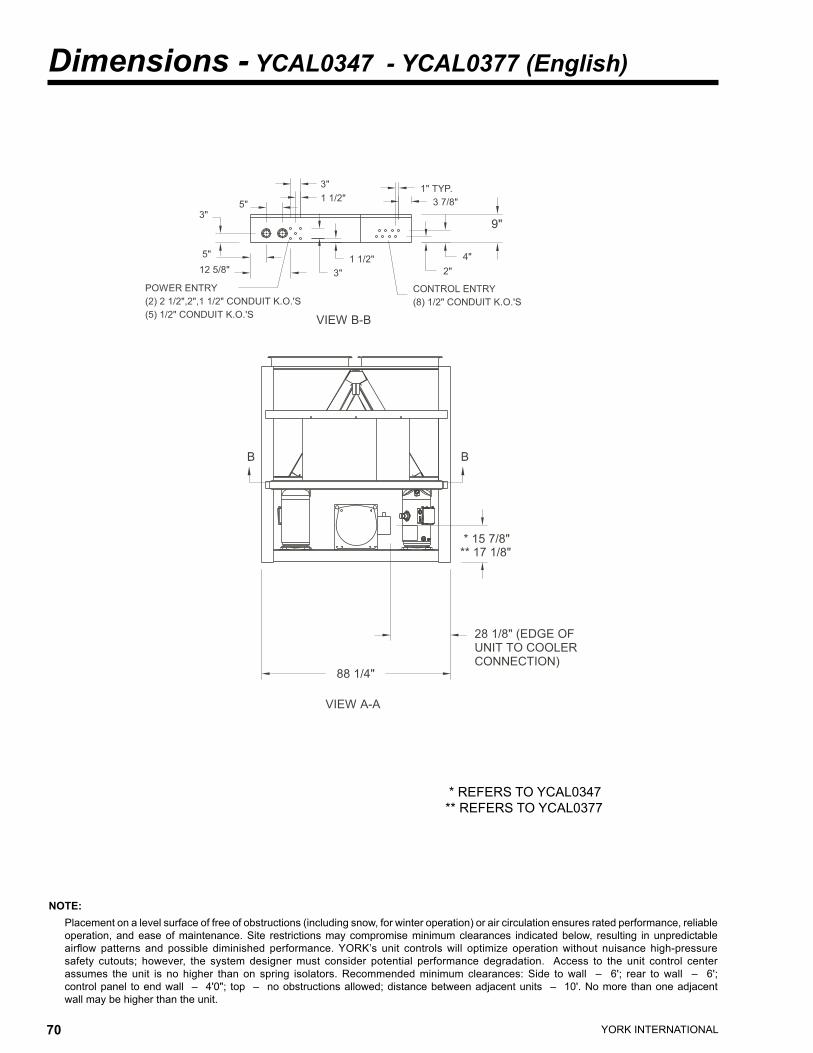
YORK INTERNATIONAL70 YORK INTERNATIONAL 71
FORM 150.62-EG2
Dimensions - YCAL0347 - YCAL0377 (English)
NOTE: Placement on a level surface of free of obstructions (including snow, for winter operation) or air circulation ensures rated performance, reliable
operation, and ease of maintenance. Site restrictions may compromise minimum clearances indicated below, resulting in unpredictable airflow patterns and possible diminished performance. YORK’s unit controls will optimize operation without nuisance high-pressure safety cutouts; however, the system designer must consider potential performance degradation. Access to the unit control center assumes the unit is no higher than on spring isolators. Recommended minimum clearances: Side to wall – 6'; rear to wall – 6'; control panel to end wall – 4'0"; top – no obstructions allowed; distance between adjacent units – 10'. No more than one adjacent wall may be higher than the unit.
��������
�������
��������
�
�����������������������������������������
�
��������������������
�����������������������
��
�����������������������������������
��
�����������
���������
�������� ������
��
������������������������������������
������
�������
��
��
��
* REFERS TO YCAL0347** REFERS TO YCAL0377

YORK INTERNATIONAL70 YORK INTERNATIONAL 71
FORM 150.62-EG2
ALUMINUM COPPER
YCALCenter of Gravity (in.)
X Y Z0347 79.5 44.1 40.70377 79.5 44.1 40.7
YCALCenter of Gravity (in.)
X Y Z0347 79.5 44.1 42.70377 79.5 44.1 42.7
* REFERS TO YCAL0347** REFERS TO YCAL0377
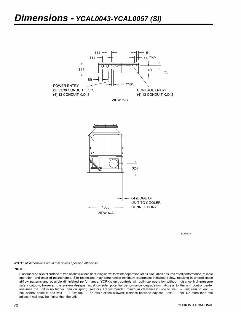
YORK INTERNATIONAL72 YORK INTERNATIONAL 73
FORM 150.62-EG2
NOTE: Placement on a level surface of free of obstructions (including snow, for winter operation) or air circulation ensures rated performance, reliable
operation, and ease of maintenance. Site restrictions may compromise minimum clearances indicated below, resulting in unpredictable airflow patterns and possible diminished performance. YORK’s unit controls will optimize operation without nuisance high-pressure safety cutouts; however, the system designer must consider potential performance degradation. Access to the unit control center assumes the unit is no higher than on spring isolators. Recommended minimum clearances: Side to wall – 2m; rear to wall – 2m; control panel to end wall – 1.2m; top – no obstructions allowed; distance between adjacent units – 3m. No more than one adjacent wall may be higher than the unit.
Dimensions - YCAL0043-YCAL0057 (SI)
LD04870
��
�������
���
�������
��
���
���
��
���
�����������
������������������������������������������
��������
�������������������������������������
��
���
����
��������
�����������
��������������
�����������
NOTE: All dimensions are in mm unless specified otherwise.

YORK INTERNATIONAL72 YORK INTERNATIONAL 73
FORM 150.62-EG2
���
����
��
��
����
���
���
����
��
��
���
���
���
��
��� ����
��� ����
�����
�
��
���������
�����������������
�������������������
��
�����������������������
�
�
������
���
�
��������
�������
��������
�������������������������
�����������
LD04871
ALUMINUM COPPER
YCALCenter of Gravity (mm)
X Y Z0043 1138 612 7190057 1138 611 719
YCALCenter of Gravity (mm)
X Y Z0043 1153 615 7310057 1153 615 731

YORK INTERNATIONAL74 YORK INTERNATIONAL 75
FORM 150.62-EG2
NOTE: Placement on a level surface of free of obstructions (including snow, for winter operation) or air circulation ensures rated performance, reliable
operation, and ease of maintenance. Site restrictions may compromise minimum clearances indicated below, resulting in unpredictable airflow patterns and possible diminished performance. YORK’s unit controls will optimize operation without nuisance high-pressure safety cutouts; however, the system designer must consider potential performance degradation. Access to the unit control center assumes the unit is no higher than on spring isolators. Recommended minimum clearances: Side to wall – 2m; rear to wall – 2m; control panel to end wall – 1.2m; top – no obstructions allowed; distance between adjacent units – 3m. No more than one adjacent wall may be higher than the unit.
Dimensions - YCAL0073-YCAL0107 (SI)
LD04859
* Refers to Model YCAL0024 ** Refers to Model YCAL0030 and YCAL0034
��
���������������
���
���
��
��
�������
�����
���
�������
����
��������
��������
���������������������
������������������������
�����������
���������������������
�������������
�����������
��������������
�����������
NOTE: All dimensions are in mm unless specified otherwise.

YORK INTERNATIONAL74 YORK INTERNATIONAL 75
FORM 150.62-EG2
����
��
��
����
���
���
���
�����������������������������
��
��
���
���
���
��������������
�������������������������� �����������������
��� ����
�����
�
��
���������
�����������������
�������������������
�������������
�����������������������
�
�
������
���
�
��������
�������
��������
�������������������������
�����������
LD04860
* Refers to Model YCAL0073 ** Refers to Model YCAL0087 and YCAL0107
ALUMINUM COPPER
YCALCenter of Gravity (mm)
X Y Z0073 1143 619 8970087 1144 620 8870107 1143 646 860
YCALCenter of Gravity (mm)
X Y Z0073 1162 623 9200087 1163 623 9090107 1160 647 882

YORK INTERNATIONAL76 YORK INTERNATIONAL 77
FORM 150.62-EG2
NOTE: Placement on a level surface of free of obstructions (including snow, for winter operation) or air circulation ensures rated performance, reliable
operation, and ease of maintenance. Site restrictions may compromise minimum clearances indicated below, resulting in unpredictable airflow patterns and possible diminished performance. YORK’s unit controls will optimize operation without nuisance high-pressure safety cutouts; however, the system designer must consider potential performance degradation. Access to the unit control center assumes the unit is no higher than on spring isolators. Recommended minimum clearances: Side to wall – 2m; rear to wall – 2m; control panel to end wall – 1.2m; top – no obstructions allowed; distance between adjacent units – 3m. No more than one adjacent wall may be higher than the unit.
Dimensions - YCAL0117-YCAL0173 (SI)
LD04874
��������������������������� ������������������������������������������
���
������������������������������������
��������
����
� �
��������
�����������
��
�������������
�����
���
�����
��
��
��
���������
���
NOTE: All dimensions are in mm unless specified otherwise.

YORK INTERNATIONAL76 YORK INTERNATIONAL 77
FORM 150.62-EG2
�
���������
������������������������������������
�
���
�
����
���������������
����
����
����
�������������
���
���
���� ���
��
�
�����������
����������
�
�
����
��
��������������������
��� ��
�����������
�������������
������
��� ����
� �
� �
LD04875
ALUMINUM COPPER
YCALCenter of Gravity (mm)
X Y Z0117 1490 1021 10470133 1481 1026 10090147 1483 1021 10040157 1484 1025 10030173 1485 1021 1001
YCALCenter of Gravity (mm)
X Y Z0117 1482 1021 10230133 1483 1026 10180147 1485 1021 10130157 1486 1025 10120173 1487 1021 1010

YORK INTERNATIONAL78 YORK INTERNATIONAL 79
FORM 150.62-EG2
Dimensions -YCAL0197-YCAL0253 (SI)
NOTE: Placement on a level surface of free of obstructions (including snow, for winter operation) or air circulation ensures rated performance, reliable
operation, and ease of maintenance. Site restrictions may compromise minimum clearances indicated below, resulting in unpredictable airflow patterns and possible diminished performance. YORK’s unit controls will optimize operation without nuisance high-pressure safety cutouts; however, the system designer must consider potential performance degradation. Access to the unit control center assumes the unit is no higher than on spring isolators. Recommended minimum clearances: Side to wall – 2m; rear to wall – 2m; control panel to end wall – 1.2m; top – no obstructions allowed; distance between adjacent units – 3m. No more than one adjacent wall may be higher than the unit.
LD04878
����
�������������������������������������
���
��������
����
�����
���
���
����
��
����������������������������������
���������
� �
��������
�����������������������������������������������������������
���
NOTE: All dimensions are in mm unless specified otherwise.

YORK INTERNATIONAL78 YORK INTERNATIONAL 79
FORM 150.62-EG2
����
��� ����
��� ����
������������������������������������ ��
�������������������������
����
���
����
���������������������������
����
���
���
��
��
��
�
�
�
�
���������
��
���
�������������
���
������
�
����
�����������
����������
�
� �
� �
LD04879
ALUMINUM COPPER
YCALCenter of Gravity (mm)
X Y Z0197 1435 1162 10010217 1437 1154 10020237 1438 1161 10030253 1437 1154 991
YCALCenter of Gravity (mm)
X Y Z0197 1440 1162 10160217 1442 1154 10170237 1443 1160 10180253 1442 1154 1006

YORK INTERNATIONAL80 YORK INTERNATIONAL 81
FORM 150.62-EG2
Dimensions - YCAL0287-YCAL0317 (SI)
NOTE: Placement on a level surface of free of obstructions (including snow, for winter operation) or air circulation ensures rated performance, reliable
operation, and ease of maintenance. Site restrictions may compromise minimum clearances indicated below, resulting in unpredictable airflow patterns and possible diminished performance. YORK’s unit controls will optimize operation without nuisance high-pressure safety cutouts; however, the system designer must consider potential performance degradation. Access to the unit control center assumes the unit is no higher than on spring isolators. Recommended minimum clearances: Side to wall – 2m; rear to wall – 2m; control panel to end wall – 1.2m; top – no obstructions allowed; distance between adjacent units – 3m. No more than one adjacent wall may be higher than the unit.
NOTE: All dimensions are in mm unless specified otherwise.
��������
����
��������
�
�������������������������������������
�
���
���������������������
��
���������������������������
���
�����������
������
��
���� ��
��
����������������������������������
��
�������
���
���

YORK INTERNATIONAL80 YORK INTERNATIONAL 81
FORM 150.62-EG2
ALUMINUM COPPER
YCALCenter of Gravity (mm)
X Y Z0287 1801 1120 1069
YCALCenter of Gravity (mm)
X Y Z0287 1788 1120 1128
�����������������������������������������

YORK INTERNATIONAL82 YORK INTERNATIONAL 83
FORM 150.62-EG2
NOTE: Placement on a level surface of free of obstructions (including snow, for winter operation) or air circulation ensures rated performance, reliable
operation, and ease of maintenance. Site restrictions may compromise minimum clearances indicated below, resulting in unpredictable airflow patterns and possible diminished performance. YORK’s unit controls will optimize operation without nuisance high-pressure safety cutouts; however, the system designer must consider potential performance degradation. Access to the unit control center assumes the unit is no higher than on spring isolators. Recommended minimum clearances: Side to wall – 2m; rear to wall – 2m; control panel to end wall – 1.2m; top – no obstructions allowed; distance between adjacent units – 3m. No more than one adjacent wall may be higher than the unit.
NOTE: All dimensions are in mm unless specified otherwise.
Dimensions - YCAL0347 - YCAL0377 (SI)
������������
* Refers to Model YCAL0347 ** Refers to Model YCAL0377

YORK INTERNATIONAL82 YORK INTERNATIONAL 83
FORM 150.62-EG2
ALUMINUM COPPER
YCALCenter of Gravity (mm)
X Y Z0317 1801 1120 10690347 2019 1120 10330377 2019 1120 1033
YCALCenter of Gravity (mm)
X Y Z0317 1788 1120 11280347 2019 1120 10850377 2019 1120 1085
����������������������������������������
* Refers to Model YCAL0347 ** Refers to Model YCAL0377

YORK INTERNATIONAL84 YORK INTERNATIONAL 85
FORM 150.62-EG2
Weight DistributionALUMINUM FIN COILS
SI Units
English Units
YCALAluminum Fin Coil Weight Distribution (lbs)
A B C D E F G H Total0043 668 524 760 596 --- --- --- --- 2,548
0057 672 527 765 600 --- --- --- --- 2,564
0073 776 615 864 685 --- --- --- --- 2,940
0087 758 680 842 755 --- --- --- --- 3,036
0107 882 789 903 807 --- --- --- --- 3,381
0117 1,261 1,200 1,266 1,204 --- --- --- --- 4,931
0133 1,283 1,223 1,274 1,214 --- --- --- --- 4,994
0147 1,292 1,235 1,297 1,239 --- --- --- --- 5,064
0157 1,318 1,263 1,311 1,256 --- --- --- --- 5,148
0173 1,333 1,280 1,338 1,284 --- --- --- --- 5,236
0197 1,655 1,466 1,637 1,450 --- --- --- --- 6,208
0217 1,688 1,501 1,692 1,505 --- --- --- --- 6,386
0237 1,742 1,552 1,727 1,538 --- --- --- --- 6,558
0253 1,792 1,593 1,797 1,597 --- --- --- --- 6,779
0287 1,573 836 1,129 1,573 836 1,126 --- --- 7,073
0317 1,615 840 1,146 1,615 840 1,144 --- --- 7,201
0347 1,360 1,162 880 829 1,360 1,162 882 832 8,466
0377 1,401 1,199 909 856 1,399 1,197 906 854 8,721
YCALAluminum Fin Coil Weight Distribution (kg)
A B C D E F G H Total0043 303 238 345 270 --- --- --- --- 1,156
0057 305 239 347 272 --- --- --- --- 1,163
0073 352 279 392 311 --- --- --- --- 1,333
0087 344 309 382 343 --- --- --- --- 1,377
0107 400 358 410 366 --- --- --- --- 1,534
0117 572 544 574 546 --- --- --- --- 2,236
0133 582 555 578 551 --- --- --- --- 2,265
0147 586 560 588 562 --- --- --- --- 2,297
0157 598 573 595 570 --- --- --- --- 2,335
0173 605 581 607 583 --- --- --- --- 2,375
0197 751 665 742 658 --- --- --- --- 2,816
0217 766 681 768 683 --- --- --- --- 2,897
0237 790 704 783 698 --- --- --- --- 2,975
0253 813 723 815 724 --- --- --- --- 3,075
0287 715 380 513 715 380 512 --- --- 3,215
0317 734 382 521 734 382 520 --- --- 3,273
0347 618 528 400 377 618 528 401 378 3,848
0377 637 545 413 389 636 544 412 388 3,964

YORK INTERNATIONAL84 YORK INTERNATIONAL 85
FORM 150.62-EG2
COPPER FIN COILSEnglish Units
SI Units
Copper Fin Coil Weight Distribution (lbs)YCAL A B C D E F G H Total0043 718 581 809 654 --- --- --- --- 2,762
0057 722 584 814 658 --- --- --- --- 2,778
0073 854 704 941 776 --- --- --- --- 3,275
0087 830 776 912 853 --- --- --- --- 3,371
0107 954 885 974 904 --- --- --- --- 3,717
0117 1,354 1,292 1,358 1,296 --- --- --- --- 5,300
0133 1,375 1,315 1,366 1,307 --- --- --- --- 5,363
0147 1,384 1,327 1,389 1,332 --- --- --- --- 5,433
0157 1,410 1,355 1,403 1,348 --- --- --- --- 5,517
0173 1,426 1,372 1,430 1,377 --- --- --- --- 5,605
0197 1,766 1,577 1,747 1,561 --- --- --- --- 6,651
0217 1,799 1,612 1,803 1,616 --- --- --- --- 6,829
0237 1,852 1,662 1,838 1,649 --- --- --- --- 7,001
0253 1,903 1,704 1,907 1,708 --- --- --- --- 7,222
0287 1,760 933 1,258 1,760 933 1258 --- --- 7,902
0317 1,800 937 1,278 1,800 937 1278 --- --- 8,030
0347 1,511 1,291 979 922 1,511 1,291 979 922 9,407
0377 1,553 1,327 1,001 948 1,553 1,327 1,005 948 9,662
YCALCopper Fin Coil Weight Distribution (kg)
A B C D E F G H Total
0043 326 263 367 297 --- --- --- --- 1,253
0057 327 265 369 299 --- --- --- --- 1,260
0073 387 319 427 352 --- --- --- --- 1,486
0087 377 352 414 387 --- --- --- --- 1,529
0107 433 402 442 410 --- --- --- --- 1,686
0117 614 586 616 588 --- --- --- --- 2,404
0133 624 597 620 593 --- --- --- --- 2,432
0147 628 602 630 604 --- --- --- --- 2,464
0157 640 615 637 612 --- --- --- --- 2,502
0173 647 622 649 624 --- --- --- --- 2,542
0197 801 715 793 708 --- --- --- --- 3,017
0217 816 731 818 733 --- --- --- --- 3,098
0237 840 754 833 748 --- --- --- --- 3,176
0253 863 773 865 775 --- --- --- --- 3,276
0287 800 424 572 800 424 572 --- --- 3,592
0317 818 426 581 818 426 581 --- --- 3,650
0347 687 587 445 419 687 587 445 419 4,276
0377 706 603 455 431 706 603 457 431 4,392

YORK INTERNATIONAL86 YORK INTERNATIONAL 87
FORM 150.62-EG2
Isolator Selections - (Aluminum Coils)
1” DEFLECTION ISOLATOR SELECTION - VMC TYPEAluminum Fin, 1” Isolator Selections
VMC Type CP-x-xxYCAL A B C D E F G H0043 CP-1-27 CP-1-26 CP-1-28 CP-1-27 --- --- --- ---
0057 CP-1-27 CP-1-26 CP-1-28 CP-1-27 --- --- --- ---
0073 CP-1-28 CP-1-27 CP-1-28 CP-1-28 --- --- --- ---
0087 CP-1-28 CP-1-27 CP-1-28 CP-1-28 --- --- --- ---
0107 CP-1-28 CP-1-28 CP-1-31 CP-1-28 --- --- --- ---
0117 CP-2-27 CP-2-27 CP-2-27 CP-2-27 --- --- --- ---
0133 CP-2-27 CP-2-27 CP-2-27 CP-2-27 --- --- --- ---
0147 CP-2-27 CP-2-27 CP-2-27 CP-2-27 --- --- --- ---
0157 CP-2-27 CP-2-27 CP-2-27 CP-2-27 --- --- --- ---
0173 CP-2-27 CP-2-27 CP-2-27 CP-2-27 --- --- --- ---
0197 CP-2-28 CP-2-28 CP-2-28 CP-2-28 --- --- --- ---
0217 CP-2-28 CP-2-28 CP-2-28 CP-2-28 --- --- --- ---
0237 CP-2-28 CP-2-28 CP-2-28 CP-2-28 --- --- --- ---
0253 CP-2-28 CP-2-28 CP-2-28 CP-2-28 --- --- --- ---
0287 CP-2-31 CP-2-26 CP-2-27 CP-2-31 CP-2-26 CP-2-27 --- ---
0317 CP-2-31 CP-2-26 CP-2-27 CP-2-31 CP-2-26 CP-2-27 --- ---
0347 CP-2-28 CP-2-27 CP-2-26 CP-2-26 CP-2-28 CP-2-27 CP-2-26 CP-2-26
0377 CP-2-28 CP-2-27 CP-2-26 CP-2-26 CP-2-28 CP-2-27 CP-2-26 CP-2-26
Aluminum Fin, Seismic Isolator Selections
YCALVMC Model # AEQM-xxxx
A B C D E F G H0043 AEQM-97 AEQM-96 AEQM-98 AEQM-97 --- --- --- ---
0057 AEQM-97 AEQM-96 AEQM-98 AEQM-97 --- --- --- ---
0073 AEQM-98 AEQM-97 AEQM-98 AEQM-98 --- --- --- ---
0087 AEQM-98 AEQM-97 AEQM-98 AEQM-98 --- --- --- ---
0107 AEQM-98 AEQM-98 AEQM-99 AEQM-98 --- --- --- ---
0117 AEQM-1300 AEQM-1300 AEQM-1300 AEQM-1300 --- --- --- ---
0133 AEQM-1300 AEQM-1300 AEQM-1300 AEQM-1300 --- --- --- ---
0147 AEQM-1300 AEQM-1300 AEQM-1300 AEQM-1300 --- --- --- ---
0157 AEQM-1600 AEQM-1300 AEQM-1600 AEQM-1300 --- --- --- ---
0173 AEQM-1600 AEQM-1300 AEQM-1600 AEQM-1300 --- --- --- ---
0197 AEQM-1625 AEQM-1600 AEQM-1625 AEQM-1600 --- --- --- ---
0217 AEQM-1625 AEQM-1600 AEQM-1625 AEQM-1600 --- --- --- ---
0237 AEQM-1625 AEQM-1600 AEQM-1625 AEQM-1600 --- --- --- ---
0253 AEQM-1625 AEQM-1600 AEQM-1625 AEQM-1600 --- --- --- ---
0287 AEQM-1625 AEQM-1000 AEQM-1300 AEQM-1625 AEQM-1000 AEQM-1300 --- ---
0317 AEQM-1625 AEQM-1000 AEQM-1300 AEQM-1625 AEQM-1000 AEQM-1300 --- ---
0347 AEQM-1600 AEQM-1600 AEQM-1000 AEQM-1000 AEQM-1600 AEQM-1300 AEQM-1000 AEQM-1000
0377 AEQM-1600 AEQM-1600 AEQM-1000 AEQM-1000 AEQM-1600 AEQM-1300 AEQM-1000 AEQM-1000
SEISMIC ISOLATOR SELECTION - VMC TYPE

YORK INTERNATIONAL86 YORK INTERNATIONAL 87
FORM 150.62-EG2
NEOPRENE ISOLATOR SELECTION - VMC TYPEAluminum Fin, Neoprene Isolator Selections
YCALVMC Type RD
A B C D E F G H0043 -3 Grn -2 Gray -3 Gray -3 Grn --- --- --- ---
0057 -3 Grn -2 Gray -3 Gray -3 Grn --- --- --- ---
0073 -3 Gray -3 Grn -3 Gray -3 Grn --- --- --- ---
0087 -3 Gray -3 Grn -3 Gray -3 Grn --- --- --- ---
0107 -3 Gray -3 Grn -3 Gray -3 Grn --- --- --- ---
0117 -4 Blk -4 Blk -4 Blk -4 Blk --- --- --- ---
0133 -4 Blk -4 Blk -4 Blk -4 Blk --- --- --- ---
0147 -4 Blk -4 Blk -4 Blk -4 Blk --- --- --- ---
0157 -4 Blk -4 Blk -4 Blk -4 Blk --- --- --- ---
0173 -4 Blk -4 Blk -4 Blk -4 Blk --- --- --- ---
0197 -4 Red -4 Red -4 Red -4 Red --- --- --- ---
0217 -4 Red -4 Red -4 Red -4 Red --- --- --- ---
0237 -4 Red -4 Red -4 Red -4 Red --- --- --- ---
0253 -4 Red -4 Red -4 Red -4 Red --- --- --- ---
0287 -4 Red -3 Gray -3 Gray -4 Red -3 Gray -3 Gray --- ---
0317 -4 Red -3 Gray -3 Gray -4 Red -3 Gray -3 Gray --- ---
0347 -4 Blk -4 Blk -3 Gray -3 Gray -4 Blk -4 Blk -3 Gray -3 Gray
0377 -4 Blk -4 Blk -3 Gray -3 Gray -4 Blk -4 Blk -3 Gray -3 Gray

YORK INTERNATIONAL88 YORK INTERNATIONAL 89
FORM 150.62-EG2
Copper Fin, 1” Isolator Selections
YCALVMC Type CP-x-xx
A B C D E F G H0043 CP-1-27 CP-1-26 CP-1-28 CP-1-27 --- --- --- ---
0057 CP-1-27 CP-1-26 CP-1-28 CP-1-27 --- --- --- ---
0073 CP-1-28 CP-1-27 CP-1-31 CP-1-28 --- --- --- ---
0087 CP-1-28 CP-1-27 CP-1-31 CP-1-28 --- --- --- ---
0107 CP-1-31 CP-1-28 CP-1-31 CP-1-28 --- --- --- ---
0117 CP-2-27 CP-2-27 CP-2-27 CP-2-27 --- --- --- ---
0133 CP-2-27 CP-2-27 CP-2-27 CP-2-27 --- --- --- ---
0147 CP-2-27 CP-2-27 CP-2-27 CP-2-27 --- --- --- ---
0157 CP-2-27 CP-2-27 CP-2-27 CP-2-27 --- --- --- ---
0173 CP-2-27 CP-2-27 CP-2-27 CP-2-27 --- --- --- ---
0197 CP-2-28 CP-2-28 CP-2-28 CP-2-28 --- --- --- ---
0217 CP-2-28 CP-2-28 CP-2-28 CP-2-28 --- --- --- ---
0237 CP-2-31 CP-2-28 CP-2-31 CP-2-28 --- --- --- ---
0253 CP-2-31 CP-2-28 CP-2-31 CP-2-28 --- --- --- ---
0287 CP-2-31 CP-2-26 CP-1-27 CP-2-31 CP-2-26 CP-1-27 --- ---
0317 CP-2-31 CP-2-26 CP-1-27 CP-2-31 CP-2-26 CP-1-27 --- ---
0347 CP-2-28 CP-1-27 CP-2-26 CP-2-26 CP-2-28 CP-1-27 CP-2-26 CP-2-26
0377 CP-2-28 CP-1-27 CP-2-26 CP-2-26 CP-2-28 CP-1-27 CP-2-26 CP-2-26
Copper Fin, Seismic Isolator Selections
YCALVMC Model # AEQM-xxxx
A B C D E F G H0043 AEQM-97 AEQM-96 AEQM-98 AEQM-97 --- --- --- ---
0057 AEQM-97 AEQM-96 AEQM-98 AEQM-97 --- --- --- ---
0073 AEQM-98 AEQM-97 AEQM-99 AEQM-98 --- --- --- ---
0087 AEQM-98 AEQM-97 AEQM-99 AEQM-98 --- --- --- ---
0107 AEQM-99 AEQM-98 AEQM-99 AEQM-98 --- --- --- ---
0117 AEQM-1600 AEQM-1600 AEQM-1600 AEQM-1300 --- --- --- ---
0133 AEQM-1600 AEQM-1600 AEQM-1600 AEQM-1300 --- --- --- ---
0147 AEQM-1600 AEQM-1600 AEQM-1600 AEQM-1600 --- --- --- ---
0157 AEQM-1600 AEQM-1600 AEQM-1600 AEQM-1600 --- --- --- ---
0173 AEQM-1600 AEQM-1600 AEQM-1600 AEQM-1600 --- --- --- ---
0197 AEQM-1625 AEQM-1600 AEQM-1625 AEQM-1600 --- --- --- ---
0217 AEQM-1625 AEQM-1625 AEQM-1625 AEQM-1625 --- --- --- ---
0237 AEQM-1625 AEQM-1625 AEQM-1625 AEQM-1625 --- --- --- ---
0253 AEQM-1625 AEQM-1625 AEQM-1625 AEQM-1625 --- --- --- ---
0287 AEQM-1625 AEQM-1000 AEQM-1600 AEQM-1625 AEQM-1000 AEQM-1600 --- ---
0317 AEQM-1625 AEQM-1000 AEQM-1600 AEQM-1625 AEQM-1000 AEQM-1600 --- ---
0347 AEQM-1625 AEQM-1600 AEQM-1300 AEQM-1000 AEQM-1625 AEQM-1600 AEQM-1300 AEQM-1000
0377 AEQM-1625 AEQM-1600 AEQM-1300 AEQM-1000 AEQM-1625 AEQM-1600 AEQM-1300 AEQM-1000
Isolator Selections - (Copper Coils)
1” DEFLECTION ISOLATOR SELECTION - VMC TYPE
SEISMIC ISOLATOR SELECTION - VMC TYPE

YORK INTERNATIONAL88 YORK INTERNATIONAL 89
FORM 150.62-EG2
Copper Fin, Neoprene Isolator Selections
YCALVMC Type RD
A B C D E F G H0043 -3 Grn -3 Grn -3 Gray -3 Grn --- --- --- ---
0057 -3 Grn -3 Grn -3 Gray -3 Grn --- --- --- ---
0073 -3 Gray -3 Gray -3 Gray -3 Gray --- --- --- ---
0087 -3 Gray -3 Gray -3 Gray -3 Gray --- --- --- ---
0107 -3 Gray -3 Gray -3 Gray -3 Gray --- --- --- ---
0117 -4 Blk -4 Blk -4 Blk -4 Blk --- --- --- ---
0133 -4 Blk -4 Blk -4 Blk -4 Blk --- --- --- ---
0147 -4 Blk -4 Blk -4 Blk -4 Blk --- --- --- ---
0157 -4 Blk -4 Blk -4 Blk -4 Blk --- --- --- ---
0173 -4 Blk -4 Blk -4 Blk -4 Blk --- --- --- ---
0197 -4 Red -4 Red -4 Red -4 Red --- --- --- ---
0217 -4 Red -4 Red -4 Red -4 Red --- --- --- ---
0237 -4 Red -4 Red -4 Red -4 Red --- --- --- ---
0253 -4 Red -4 Red -4 Red -4 Red --- --- --- ---
0287 -4 Red -3 Gray -4 Blk -4 Red -3 Gray -4 Blk --- ---
0317 -4 Red -3 Gray -4 Blk -4 Red -3 Gray -4 Blk --- ---
0347 -4 Red -4 Blk -3 Gray -3 Gray -4 Red -4 Blk -3 Gray -3 Gray
0377 -4 Red -4 Blk -3 Gray -3 Gray -4 Red -4 Blk -3 Gray -3 Gray
NEOPRENE ISOLATOR SELECTION - VMC TYPE

YORK INTERNATIONAL90 YORK INTERNATIONAL 91
FORM 150.62-EG2
Isolator Selections
DIMENSIONS
TYPE CP 1
TYPE CP 2
LD03839
LD03840
ISOLATOR SPRING IDENTIFICATION TABLE1" DEFLECTION SEISMIC
MODEL PART- # COLOR MODEL PART # COLORCP-1-26 308439-26 PURPLE AEQM-96 301055-96 BLACKCP-1-27 308439-27 ORANGE AEQM-97 301055-97 WHITECP-1-28 308439-28 GREEN AEQM-98 301055-98 GRAYCP-1-31 308439-31 GRAY AEQM-99 301055-99 BLUECP-2-25 308439-25 RED AEQM-1000 30106-1000 GREENCP-2-26 308692-26 PURPLE AEQM-1300 30106-1300 YELLOWCP-2-27 308962-27 ORANGE AEQM-1600 301060-1600 GRAYCP-2-28 308692-28 GREEN AEQM-1625 301060-1625 REDCP-2-31 308692-31 GRAY AEQM-1628 301060-1628 GRAY/GREEN

YORK INTERNATIONAL90 YORK INTERNATIONAL 91
FORM 150.62-EG2
DIMENSIONS
LD04045
TYPE AEQM
MODEL # A B C D E F G H JAEQM-97 7 5-1/2 4-1/2 2-1/2 5/8 1/4 7-1/4 5/8 3/8AEQM-98 7 5-1/2 4-1/2 2-1/2 5/8 1/4 7-1/4 5/8 3/8AEQM-99 7 5-1/2 4-1/2 2-1/2 5/8 1/4 7-1/4 5/8 3/8
AEQM-1000 8-1/2 6-1/2 6 4-1/2 3/4 3/8 8-3/8 7/8 1/2AEQM-1300 8-1/2 6-1/2 6 4-1/2 3/4 3/8 8-3/8 7/8 1/2AEQM-1600 8-1/2 6-1/2 6 4-1/2 3/4 3/8 8-3/8 7/8 1/2AEQM-1625 8-1/2 6-1/2 6 4-1/2 3/4 3/8 8-3/8 7/8 1/2AEQM-1628 8-1/2 6-1/2 6 4-1/2 3/4 3/8 8-3/8 7/8 1/2

YORK INTERNATIONAL92 YORK INTERNATIONAL 93
FORM 150.62-EG2
LEGEND ACR-LINE ACROSS THE LINE START C.B. CIRCUIT BREAKER D.E. DUAL ELEMENT FUSE DISC SW DISCONNECT SWITCH FACT MOUNT CB FACTORY MOUNTED CIRCUIT BREAKER FLA FULL LOAD AMPS HZ HERTZ MAX MAXIMUM MCA MINIMUM CIRCUIT AMPACITY MIN MINIMUM MIN NF MINIMUM NON FUSED RLA RATED LOAD AMPS S.P. WIRE SINGLE POINT WIRING UNIT MTD SERV SW UNIT MOUNTED SERVICE (NON-FUSED DISCONNECT SWITCH) LRA LOCKED ROTOR AMPS
VOLTAGE CODE-50=380/415-3-50
Electrical Data
1. Minimum Circuit Ampacity (MCA) is based on 125% of the rated load amps for the largest motor plus 100% of the rated load amps for all other loads included in the circuit, per N.E.C. Article 430-24. If the optional Factory Mounted Control Transformer is provided, add the following MCA values to the electrical tables for the system providing power to the transformer: -17, add 2.5 amps; -28, add 2.3 amps; -40, add 1.5 amps, -46, add 1.3 amps; -58, add 1 amps.
2. The minimum recommended disconnect switch is based on 115% of the rated load amps for all loads included in the circuit, per N.E.C. Article 440.
3. Minimum fuse size is based upon 150% of the rated load amps for the largest motor plus 100% of the rated load amps for all other loads included in the circuit to avoid nuisance trips at start-up due to lock rotor amps. It is not recommended in applications where brown outs, frequent starting and stopping of the unit, and/or operation at ambient temperatures in excess of 95ºF (35ºC) is anticipated.
4. Maximum fuse size is based upon 225% of the rated load amps for the largest motor plus 100% of the rated load amps for all other loads included in the circuit, per N.E.C. Article 440-22.
5. Circuit breakers must be UL listed and CSA certified and maximum size is based on 225% of the rated load amps for the largest motor plus 100% of the rated load amps for all other loads included in the circuit. Exception: YCAL0014 and YCAL0020 must have the optional factory overloads installed to use a standard circuit breaker. Otherwise, an HACR-type circuit breakers must be used. Maximum HACR circuit breaker rating is based on 225% of the rated load amps for the largest motor plus 100% of the rated load amps for all other loads included in the circuit.
6. The “INCOMING WIRE RANGE” is the minimum and maximum wire size that can be accommodated by the unit wiring lugs. The (2) preceding the wire range indicates the number of termination points available per phase of the wire range specified. Actual wire size and number of wires per phase must be determined based on the National Electrical Code, using copper connectors only. Field wiring must also comply with local codes.
7. A ground lug is provided for each compressor system to accommodate a field grounding conductor per N.E.C. Table 250-95. A control circuit grounding lug is also supplied.
8. The supplied disconnect is a “Disconnecting Means” as defined in the N.E.C. 100, and is intended for isolating the unit for the available power supply to perform maintenance and troubleshooting. This disconnect is not intended to be a Load Break Device.
9. Field Wiring by others which complies to the National Electrical Code & Local Codes.
NOTES:

YORK INTERNATIONAL92 YORK INTERNATIONAL 93
FORM 150.62-EG2
INTENTIONALLY LEFT BLANK

YORK INTERNATIONAL94 YORK INTERNATIONAL 95
FORM 150.62-EG2
Electrical DataYCAL0043 - YCAL0253
SINGLE POINT ON YCAL0043-0107 MODELS; DUAL POINT ON YCAL0117-0253 MODELS (See Fig. 1 or 2)(One or Two Field Provided Power Supply Circuits to the chiller. Field connections to Factory Provided Terminal Block(s) per system)
OVER CURRENT PROTECTION, UNIT VOLTAGE UNIT VOLTAGE CONTROL POWER MCA SEE NOTE B NF DISC Sw NOTE A MIN MAXMODELS w/oCONTROL TRANS 115-1-60/50 15A 10A 15A 30 A / 240VMODLES W.CONTROL TRANS. -50 380/415-3-50 15A 10A 15A 30 A / 480V
A. Minimum #14 AWG, 75°C, Copper Recommended
B. Minimum and Maximum Over Current Protection, Dual Element Fuse or Circuit Breaker
MODEL YCAL VOLT HZ
SYSTEM #1 FIELD SUPPLIED WIRING SYSTEM #1 COMPRESSOR & FAN
MCA1MIN N/F
DISC SW2
D.E. FUSE CKT. BKR.5 INCOMING (LUGS) WIRE
RANGE6
COMPR. #1 COMPR. #2 COMPR. #3 FANS
MIN3 MAX4 MIN MAX RLA LRA RLA LRA RLA LRA QTY FLA(EA)
0043 380/415 50 35 60 40 45 40 45 # 10 - # 1 12.0 99 12.0 99 — — 2 4.00057 380/415 50 46 60 50 60 50 60 # 10 - # 1 16.6 127 16.6 127 — — 2 4.00073 380/415 50 53 60 60 70 60 70 # 10 - # 1 19.9 167 19.9 167 — — 2 4.00087 380/415 50 62 100 70 80 70 80 # 10 - # 1 23.9 198 23.9 198 — — 2 4.00107 380/415 50 73 100 80 90 80 90 # 10 - # 1 19.9 167 19.9 167 19.9 167 2 4.00117 380/415 50 46 60 50 60 50 60 # 10 - # 1 16.6 127 16.6 127 — — 2 4.00133 380/415 50 53 60 60 70 60 70 # 10 - # 1 19.9 167 19.9 167 — — 2 4.00147 380/415 50 53 60 60 70 60 70 # 10 - # 1 19.9 167 19.9 167 — — 2 4.00157 380/415 50 62 100 70 80 70 80 # 10 - # 1 23.9 198 23.9 198 — — 2 4.00173 380/415 50 62 100 70 80 70 80 # 10 - # 1 23.9 198 23.9 198 — — 2 4.00197 380/415 50 73 100 80 90 80 90 # 10 - # 1 19.9 167 19.9 167 19.9 167 2 4.00217 380/415 50 73 100 80 90 80 90 # 10 - # 1 19.9 167 19.9 167 19.9 167 2 4.00237 380/415 50 86 100 100 100 100 100 # 10 - # 1 23.9 198 23.9 198 23.9 198 2 4.00253 380/415 50 86 100 100 100 100 100 # 10 - # 1 23.9 198 23.9 198 23.9 198 2 4.0
VOLTAGE RANGEVOLTAGE CODE UNIT POWER MIN. MAX.
-50 380/415-3-50 342 440

YORK INTERNATIONAL94 YORK INTERNATIONAL 95
FORM 150.62-EG2
MODEL YCAL VOLT HZ
SYSTEM #2 FIELD SUPPLIED WIRING SYSTEM #2 COMPRESSOR & FAN
MCA1MIN N/F
DISC SW2
D.E. FUSE CKT. BKR.5 INCOMING (LUGS) WIRE
RANGE6
COMPR. #1 COMPR. #2 COMPR. #3 FANSMIN3 MAX4 MIN MAX RLA LRA RLA LRA RLA LRA QTY FLA
(EA)0043 380/415 50 — — — — — — — — — — — — — — —0057 380/415 50 — — — — — — — — — — — — — — —0073 380/415 50 — — — — — — — — — — — — — — —0087 380/415 50 — — — — — — — — — — — — — — —0107 380/415 50 — — — — — — — — — — — — — — —0117 380/415 50 46 60 50 60 50 60 # 10 - # 1 16.6 127 16.6 127 — — 2 4.00133 380/415 50 46 60 50 60 50 60 # 10 - # 1 16.6 127 16.6 127 — — 2 4.00147 380/415 50 53 60 60 70 60 70 # 10 - # 1 19.9 167 19.9 167 — — 2 4.00157 380/415 50 53 60 60 70 60 70 # 10 - # 1 19.9 167 19.9 167 — — 2 4.00173 380/415 50 62 100 70 80 70 80 # 10 - # 1 23.9 198 23.9 198 — — 2 4.00197 380/415 50 62 100 70 70 70 70 # 10 - # 1 16.6 127 16.6 127 16.6 127 2 4.00217 380/415 50 73 100 80 90 80 90 # 10 - # 1 19.9 167 19.9 167 19.9 167 2 4.00237 380/415 50 73 100 80 90 80 90 # 10 - # 1 19.9 167 19.9 167 19.9 167 2 4.00253 380/415 50 86 100 100 100 100 100 # 10 - # 1 23.9 198 23.9 198 23.9 198 2 4.0
YCAL0043 - YCAL0253SINGLE POINT ON YCAL0043-0107 MODELS; DUAL POINT ON YCAL0117-0253 MODELS (See Fig. 1 or 2)
(One or Two Field Provided Power Supply Circuits to the chiller. Field connections to Factory Provided Terminal Block(s) per system)

YORK INTERNATIONAL96 YORK INTERNATIONAL 97
FORM 150.62-EG2
See Notes on page 94.
YCAL0043 - YCAL0253SINGLE POINT POWER SUPPLY CONNECTIONS (see Fig. 1)
(SINGLE POINT STANDARD ON YCAL0043-0107 MODELS; OPTIONAL ON YCAL0117-0253 MODELS. DISCONNECT AND BREAKERS OPTIONAL ON ALL MODELS)
MODEL YCAL VOLT HZ
SINGLE POINT FIELD SUPPLIED WIRING
MCA1 MIN N/F DISC SW2
D.E. FUSE CKT. BKR.5 INCOMING (LUGS) WIRE RANGE6
FACTORY SUPPLIED OPTIONALMIN3 MAX4 MIN MAX SINGLE
POINT DISCONNECT BREAKER
0043 380/415 50 35 60 40 45 40 45 # 10 - # 1 # 14 - 2 # 14 - 20057 380/415 50 46 60 50 60 50 60 # 10 - # 1 # 14 - 2 # 14 - 20073 380/415 50 53 60 60 70 60 70 # 10 - # 1 # 14 - 2 # 14 - 20087 380/415 50 62 100 70 70 70 70 # 10 - # 1 # 14 - 1/0 # 14 - 1/00107 380/415 50 73 100 80 90 80 90 # 10 - # 1 # 14 - 1/0 # 14 - 1/00117 380/415 50 87 100 100 100 100 100 # 10 - # 1 # 14 - 1/0 # 14 - 1/00133 380/415 50 94 150 100 110 100 110 # 10 - # 1 # 2 - 4/0 # 14 - 1/00147 380/415 50 101 150 110 110 110 110 # 10 - # 1 # 2 - 4/0 # 2 - 4/00157 380/415 50 110 150 125 125 125 125 # 10 - # 1 # 2 - 4/0 # 2 - 4/00173 380/415 50 118 150 125 125 125 125 # 10 - 3/0 # 2 - 4/0 # 2 - 4/00197 380/415 50 131 150 150 150 150 150 # 10 - 3/0 # 2 - 4/0 # 2 - 4/00217 380/415 50 141 200 150 150 150 150 # 10 - 3/0 # 6 - 350 # 2 - 4/00237 380/415 50 154 200 175 175 175 175 # 10 - 3/0 # 6 - 350 # 4 - 3000253 380/415 50 166 200 175 175 175 175 # 10 - 3/0 # 6 - 350 # 4 - 300

YORK INTERNATIONAL96 YORK INTERNATIONAL 97
FORM 150.62-EG2
YCAL0043- YCAL0253SINGLE POINT POWER SUPPLY CONNECTIONS (see Fig. 1)
(SINGLE POINT STANDARD ON YCAL0043-0107 MODELS; OPTIONAL ON YCAL0117-0253 MODELS. DISCONNECT AND BREAKERS OPTIONAL ON ALL MODELS)
SYSTEM #1 COMPRESSOR & FAN SYSTEM #2 FIELD SUPPLIED WIRING
COMPR. #1 COMPR. #2 COMPR. #3 FANS COMPR. #1 COMPR. #2 COMPR. #3 FANS
RLA LRA RLA LRA RLA LRA QTY FLA(EA) RLA LRA RLA LRA RLA LRA QTY FLA
(EA)12.0 99 12.0 99 — — 2 4.0 — — — — — — — —16.6 127 16.6 127 — — 2 4.0 — — — — — — — —19.9 167 19.9 167 — — 2 4.0 — — — — — — — —23.9 198 23.9 198 — — 2 4.0 — — — — — — — —19.9 167 19.9 167 19.9 167 2 4.0 — — — — — — — —16.6 127 16.6 127 — — 2 4.0 16.6 127 16.6 127 — — 2 4.019.9 167 19.9 167 — — 2 4.0 16.6 127 16.6 127 — — 2 4.019.9 167 19.9 167 — — 2 4.0 19.9 167 19.9 167 — — 2 4.023.9 198 23.9 198 — — 2 4.0 19.9 167 19.9 167 — — 2 4.023.9 198 23.9 198 — — 2 4.0 23.9 198 23.9 198 — — 2 4.019.9 167 19.9 167 19.9 167 2 4.0 16.6 127 16.6 127 16.6 127 2 4.019.9 167 19.9 167 19.9 167 2 4.0 19.9 167 19.9 167 19.9 167 2 4.023.9 198 23.9 198 23.9 198 2 4.0 19.9 167 19.9 167 19.9 167 2 4.023.9 198 23.9 198 23.9 198 2 4.0 23.9 198 23.9 198 23.9 198 2 4.0

YORK INTERNATIONAL98 YORK INTERNATIONAL 99
FORM 150.62-EG2
See Notes on page 94.
Electrical DataYCAL0287 - YCAL0377
MULTIPLE POINT POWER SUPPLY CONNECTIONS (see Fig. 3)(Two Field Provided Power Supply Circuits to the chiller. Field connections to Factory Provided Terminal Blocks (standard), Non-Fused Disconnect Switches
(optional), or Individual System Circuit Breakers (optional) per electrical system)
MODEL YCAL VOLT HZ
SYSTEM #1 FIELD SUPPLIED WIRING SYSTEM #1 COMPRESSOR & FAN
MCA1
MIN N/F
DISC SW2
D.E. FUSE CKT. BKR.5 INCOMING (LUGS) WIRE RANGE6 COMPR. #1 COMPR. #2 COMPR. #3 FANSTERMINAL
BLOCK (std)
NF DISC.
SWITCHES (opt)
CIR BREAKERS
(opt)MIN3 MAX4 MIN MAX RLA LRA RLA LRA RLA LRA QTY FLA
(EA)
0287 380/415 50 118 150 150 150 150 150 # 14 - 2/0 # 6 - 350 # 6 - 350 32.6 215 32.6 215 32.6 215 3 3.80317 380/415 50 118 150 150 150 150 150 # 14 - 2/0 # 6 - 350 # 6 - 350 32.6 215 32.6 215 32.6 215 3 3.80347 380/415 50 156 200 175 200 175 200 # 6 - 400 # 6 - 350 # 6 - 350 44.2 270 44.2 270 44.2 270 3 3.80377 380/415 50 156 200 175 200 175 200 # 6 - 400 # 6 - 350 # 6 - 350 44.2 270 44.2 270 44.2 270 3 3.8

YORK INTERNATIONAL98 YORK INTERNATIONAL 99
FORM 150.62-EG2
YCAL0287 - YCAL0377MULTIPLE POINT POWER SUPPLY CONNECTIONS (see Fig. 3)
(Two Field Provided Power Supply Circuits to the chiller. Field connections to Factory Provided Terminal Blocks (standard), Non-Fused Disconnect Switches (optional), or Individual System Circuit Breakers (optional) per electrical system)
SYSTEM #2 FIELD SUPPLIED WIRING SYSTEM #2 COMPRESSOR & FAN
MCA1MIN N/F
DISC SW2
D.E. FUSE CKT. BKR.5 INCOMING (LUGS) WIRE RANGE6
COMPR. #1 COMPR. #2 COMPR. #3 FANSTERMINAL
BLOCK (std)
NF DISC. SWITCHES
(opt)
CIR BREAKERS
(opt)MIN3 MAX4 MIN MAX RLA LRA RLA LRA RLA LRA QTY FLA(EA)
111 150 150 150 150 150 # 6 - 400 # 6 - 350 # 6 - 350 44.2 270 44.2 270 — — 3 3.8118 150 150 150 150 150 # 14 - 2/0 # 6 - 350 # 6 - 350 32.6 215 32.6 215 32.6 215 3 3.8118 200 175 200 175 200 # 14 - 2/0 # 6 - 350 # 6 - 350 32.6 215 32.6 215 32.6 215 3 3.8156 200 175 200 175 200 # 6 - 400 # 6 - 350 # 6 - 350 44.2 270 44.2 270 44.2 270 3 3.8

YORK INTERNATIONAL100 YORK INTERNATIONAL 101
FORM 150.62-EG2
See Notes on page 74.
Electrical DataYCAL0287 - YCAL0377
SINGLE POINT POWER SUPPLY CONNECTIONS WITH INDIVIDUAL SYSTEM CIRCUIT BREAKERS (see Fig. 4)(One Field Provided Power Supply Circuit to the chiller. Field connections to Factory Provided Teminal Block (optional) or Non-Fused Disconnect Switch
(optional). Includes Individual Branch Circuit Protection (Breakers) per electrical system)
See Notes on page 94.
MODEL YCAL VOLT HZ
SINGLE POINT FIELD SUPPLIED WIRING
MCA1 MIN N/F DISC SW2
D.E. FUSE CKT. BKR.5INCOMING (LUGS) WIRE
RANGE6
TERMINAL BLOCK (opt)
NF DISC. SWITCH (opt)MIN3 MAX4 MIN MAX
0287 380/415 50 221 250 250 250 250 250 # 6 - 400 # 6 - 3500317 380/415 50 227 400 250 250 250 250 # 6 - 400 (2) 3/0-5000347 380/415 50 265 400 300 300 300 300 2/0 - 500 (2) 3/0-5000377 380/415 50 300 400 300 300 300 300 2/0 - 500 (2) 3/0-500

YORK INTERNATIONAL100 YORK INTERNATIONAL 101
FORM 150.62-EG2
YCAL0287 - YCAL0377SINGLE POINT POWER SUPPLY CONNECTIONS WITH INDIVIDUAL SYSTEM CIRCUIT BREAKERS (see Fig. 4)
(One Field Provided Power Supply Circuit to the chiller. Field connections to Factory Provided Teminal Block (optional) or Non-Fused Disconnect Switch (optional). Includes Individual Branch Circuit Protection (Breakers) per electrical system)
SYSTEM #1 COMPRESSOR & FAN SYSTEM #2 FIELD SUPPLIED WIRING
COMPR. #1 COMPR. #2 COMPR. #3 FANS COMPR. #1 COMPR. #2 COMPR. #3 FANS
RLA LRA RLA LRA RLA LRA QTY FLA(EA) RLA LRA RLA LRA RLA LRA QTY FLA(EA)
32.6 215 32.6 215 32.6 215 3 3.8 44.2 270 44.2 270 — — 3 3.832.6 215 32.6 215 32.6 215 3 3.8 32.6 215 32.6 215 32.6 215 3 3.844.2 270 44.2 270 44.2 270 3 3.8 32.6 215 32.6 215 32.6 215 3 3.844.2 270 44.2 270 44.2 270 3 3.8 44.2 270 44.2 270 44.2 270 3 3.8

YORK INTERNATIONAL102 YORK INTERNATIONAL 103
FORM 150.62-EG2
Power Wiring
�������������������������������������������������� �������������������������
������
����������� �������������
��������
������
��������
������
��� ��� ��� ��� ��� ���
���
���
����������
�
�
����
�� ��
����
��������������������������������
������������������������
�����������������������������������
������������������������
�����������
���������������������
����������� ������������������������ �������������
��������
������
��������
������
��� ��� ������ ��� ��� ��� ��� ������ ��� ���
���
���
���
���
���
���
����������
�
�
����
�
�
����
�� ���� ��
����
��������������������������������
���������������������
�����������������������������������
������������������������
�����������
���������������������
������������������������������������������ ��������������������������
����������������������������������������������������
����������� �������������
���������������
����������������
������������������
��� ��� ���
���
����������
�
�
����
�� ��
����
��������������������������������
������������������������
�����������������������������������
������������������������
�����������
���������������������
����������� ������������������������ �������������
���������������
����������������
������������������
��� ��� ������ ��� ���
���
���
���
����������
�
�
����
�
�
����
�� ���� ��
����
��������������������������������
���������������������
�����������������������������������
������������������������
�����������
���������������������

YORK INTERNATIONAL102 YORK INTERNATIONAL 103
FORM 150.62-EG2
�������������������������������������������������� ��������������������������
�������������������������������������������������������
����������� �������������
����������������
��������������
���
�������������������
����������������
��������������
���
�������������������
��� ��� ��� ��� ��� ���
���
���
����������
�
�
����
�� ��
����
��������������������������������
������������������������
���������������������������
��������������������������������
�����������
���������������������
����������� ������������������������ �������������
����������������
��������������
���
�������������������
����������������
��������������
���
�������������������
��� ��� ������ ��� ��� ��� ��� ������ ��� ���
���
���
���
���
���
���
����������
�
�
����
�
�
����
�� ���� ��
����
��������������������������������
���������������������
���������������������������
��������������������������������
�����������
���������������������
������������������������������������������ ����������������������������
�����������������������������������������������������������������������
����������� �������������
�����������������
����������������
��� ��� ���
���
����������
�
�
����
�� ��
����
��������������������������������
������������������������
�����������������������������������
������������������������
�����������
���������������������
�������
��������
�������
��������
����������� ������������������������ �������������
�����������������
����������������
��� ��� ������ ��� ���
���
���
���
����������
�
�
����
�
�
����
�� ���� ��
����
��������������������������������
����������������������
�����������������������������������
������������������������
�����������
���������������������
�������
��������
�������
��������

YORK INTERNATIONAL104 YORK INTERNATIONAL 105
FORM 150.62-EG2
����
��
��
��
��
��
��
������� �����������������
���������
����������������
�
������������������������������������������
Control Wiring

YORK INTERNATIONAL104 YORK INTERNATIONAL 105
FORM 150.62-EG2
LD03611
LD03819
INTENTIONALLY LEFT BLANK
YORK INTERNATIONAL106 YORK INTERNATIONAL 107
FORM 150.62-EG2
Application DataUNIT LOCATION
The YCAL chillers are designed for outdoor installation. When selecting a site for installation, be guided by the following conditions:
1. For outdoor locations of the unit, select a place having an adequate supply of fresh air for the condenser.
2. Avoid locations beneath windows or between structures where normal operating sounds may be objectionable.
3. Installation sites may be either on a roof, or at ground level. (See FOUNDATION.)
4. The condenser fans are the propeller-type, and are not recommended for use with duct work in the condenser air stream.
5. When it is desirable to surround the unit(s), it is recommended that the screening be able to pass the required chiller CFM without exceeding 0.1" of water external static pressure.
6. Protection against corrosive environments is avail-able by supplying the units with either copper fin, cured phenolic, or epoxy coating on the condenser coils. The phenolic or epoxy coils should be offered with any units being installed at the seashore or where salt spray may hit the unit.
In installations where winter operation is intended and snow accumulations are expected, additional height must be provided to ensure normal condenser air flow.
Recommended clearances for units are given in DIMENSIONS. When the available space is less, the unit(s) must be equipped with the discharge pressure transducer option to permit high pressure unloading in the event that air recirculation were to occur.
FOUNDATION
The unit should be mounted on a flat and level founda-tion, ground or roof, capable of supporting the entire operating weight of the equipment. Operating weights are given in the PHYSICAL DATA tables.
ROOF LOCATIONS – Choose a spot with adequate structural strength to safely support the entire weight
of the unit and service personnel. Care must be taken not to damage the roof during installation. If the roof is “bonded”, consult the building contractor or architect for special installation requirements. Roof installations should incorporate the use of spring-type isolators to minimize the transmission of vibration into the building structure.
GROUND LEVEL INSTALLATIONS – It is important that the units be installed on a substantial base that will not settle, causing strain on the liquid lines and resulting in possible leaks. A one-piece concrete slab with footers extending below the frost line is highly recommended. Additionally, the slab should not be tied to the main building foundation as noises will telegraph.
Mounting holes (11/16" diameter) are provided in the steel channel for bolting the unit to its foundation. See DIMENSIONS.
For ground level installations, precautions should be taken to protect the unit from tampering by or injury to unauthorized persons. Screws on access panels will prevent casual tampering; however, further safety precautions, such as unit enclosure options, a fenced-in enclosure, or locking devices on the panels may be advisable. Check local authorities for safety regulations.
CHILLED LIQUID PIPING
The chilled liquid piping system should be laid out so that the circulating pump discharges into the cooler. The inlet and outlet cooler liquid connections are given in DIMENSIONS.
Hand stop valves are recommended for use in all lines to facilitate servicing. Drain connections should be provided at all low points to permit complete drainage of the cooler and system piping. Additionally, a strainer (40 mesh) is recommended for use on the INLET line to the cooler.
Pressure gauge connections are recommended for installation in the inlet and outlet water lines. Gauges are not furnished with the unit and are to be furnished by other suppliers.
The chilled liquid lines that are exposed to outdoor ambients should be wrapped with a supplemental heater cable and covered with insulation. As an alternative, ethylene glycol should be added to protect against freeze-up during low ambient periods.
A flow switch is available as an accessory on all units.

YORK INTERNATIONAL106 YORK INTERNATIONAL 107
FORM 150.62-EG2
Guide SpecificationsPART 1 – GENERAL
1.01 SCOPE
A. The requirements of the General Conditions, Supplementary Conditions, Division 1, and Draw-ings apply to all Work herein.
B. Provide Microprocessor controlled, multiple-scroll compressor, air-cooled, liquid chillers of the scheduled capacities as shown and indicated on the Drawings, including but not limited to:
1. Chiller package 2. Electrical power and control connections 4. Chilled water connections
1.02 QUALITY ASSURANCE
A. Products shall be Designed, Tested, Rated and Certified in accordance with, and installed in compliance with applicable sections of the following Standards and Codes:
1. ANSI/ASHRAE Standard 15 – Safety Code for Mechanical Refrigeration
2. ASHRAE 90.1– Energy Efficiency compliance. 3. ANSI/NFPA Standard 70 – National Electrical Code (N.E.C.). 4. ASME Boiler & Pressure Vessel Code, Sec-
tion VIII, Division 1. 5. ARI Standard 550/590 – Positive Displacement
Compressors and Air Cooled Rotary Screw Water-Chilling Packages.
6. Conform to Intertek Testing Services, formerly ETL, for construction of chillers. 7. Manufactured in facility registered to ISO 9002.
B. Factory Test: Chiller shall be pressure-tested, evacuated and fully charged with refrigerant and oil, and shall be factory operational run tested with water flowing through the vessel.
C. Warranty: Manufacturer shall Warrant all equipment and material of its manufacture against defects in workmanship and material for a period of one year from date of initial start-up or eighteen (18) months from date of shipment, whichever occurs first.
1.03 DELIVERY AND HANDLING
A. Unit shall be delivered to job site fully assembled,
and charged with refrigerant and oil by the Manu-facturer.
B. Unit shall be stored and handled per Manufacturer’s instructions.
PART 2 - PRODUCTS
2.01 CHILLER MATERIALS AND COMPONENTS
A. General: Install and commission, as shown on the schedules and plans, factory assembled, charged, and tested air cooled scroll compressor chiller(s) as specified herein. Chiller shall be designed, selected, and constructed using a refrigerant with Flamma-bility rating of “1”, as defined by ANSI/ASHRAE STANDARD - 34 Number Designation and Safety Classification of Refrigerants. Chiller shall include, but is not limited to: a complete system with a single refrigerant circuit 35 tons (123kW) and below, and not less than two refrigerant circuits above 35 tons (123kW), scroll compressors, direct expansion type evaporator, air-cooled condenser, refrigerant, lubrication system, interconnecting wiring, safety and operating controls including capacity control-ler, control center, motor starting components, and special features as specified herein or required for safe, automatic operation.
B. Cabinet: External structural members shall be con-structed of heavy gauge, galvanized steel coated with baked on powder paint which, when subject to ASTM B117, 500 hour, 5% salt spray test, yields minimum ASTM 1654 rating of “6”.
2.02 COMPRESSORS
Compressors: Shall be hermetic, scroll-type, including: 1. Compliant design for axial and radial sealing 2. Refrigerant flow through the compressor with 100%
suction cooled motor. 3. Large suction side free volume and oil sump to pro-
vide liquid handling capability. 4. Compressor crankcase heaters to provide extra
liquid migration protection. 5. Annular discharge check valve and reverse vent
assembly to provide low pressure drop, silent shut-down and reverse rotation protection.
6. Initial Oil charge. 7. Oil Level sightglass. 8. Vibration isolator mounts for compressors. 9. Brazed-type connections for fully hermetic refrigerant
circuits.

YORK INTERNATIONAL108 YORK INTERNATIONAL 109
FORM 150.62-EG2
2.03 REFRIGERANT CIRCUIT COMPONENTS
Each refrigerant circuit shall include: liquid line shutoff valve with charging port, low side pressure relief device, filter-drier, solenoid valve, sight glass with moisture indicator, thermostatic expansion valves, and flexible, closed-cell foam insulated suction line.
2.04 HEAT EXCHANGERS
A. Evaporator: 1. Direct expansion type with refrigerant inside
high efficiency copper tubes, chilled liquid forced over the tubes by galvanized steel baffles.
2. Constructed, tested, and stamped in accor- dance with applicable sections of ASME pressure vessel code for minimum 350 PSIG (24 bar) refrigerant side design working pres sure and 150 PSIG (10 bar) water side design working pressure.
3. Shell covered with 3⁄4" (19mm), flexible, closed cell insulation, thermal conductivity of 0.26k ([BTU/HR-Ft2 -°F]/in.) maximum. Water nozzles with grooves for mechanical couplings, and in sulated by Contractor after pipe installation.
4. Provide vent and drain fittings, and thermostati cally controlled heaters to protect to -20°F (29°C) ambient in off-cycle.
B. Air Cooled Condenser: 1. Coils: Internally enhanced, seamless copper
tubes, mechanically expanded into aluminumalloy fins with full height collars. Subcooling coilan integral part of condenser. Design workingpressure shall be 450 PSIG (31 bar).
2. Fans: Shall be dynamically and statically bal-anced, direct drive, corrosion resistant glass fiber reinforced composite blades molded into low noise, full airfoil cross section, providing vertical air discharge from extended orifices for efficiency and low sound. Each fan in its own compartment to prevent cross flow during fancycling. Guards of heavy gauge, PVC (polyvinylchloride) coated or galvanized steel.
3. Fan Motors: High efficiency, direct drive, 6 pole,3 phase, insulation class “F”, current protected,Totally Enclosed Air-Over (TEAO), rigidmounted, with double sealed, permanently lu-bricated, ball bearings.
2.05 CONTROLS
A. General: Automatic start, stop, operating, and protection sequences across the range of scheduled
conditions and transients.B. Microprocessor Enclosure: Rain and dust tight
NEMA 3R/12 (IP55) powder painted steel cabinet with hinged, latched, and gasket sealed door.
C. Microprocessor Control Center: 1. Automatic control of compressor start/stop, anti-
coincidence and anti-recycle timers, automatic pumpdown shutdown, condenser fans, evapora-tor pump, evaporator heater, unit alarm contacts, and chiller operation from 0°F to 125°F (-18°C to 52°C) ambient. Automatic reset to normal chiller operation after power failure.
2. Remote water temperature reset via a Pulse Width Modulated (PWM) input signal or up to two steps of demand (load) limiting.
3. Software stored in non-volatile memory, with programmed setpoints retained in lithium bat- tery backed real time clock (RTC) memory for minimum 5 years.
4. Forty character liquid crystal display, descrip- tions in English (or Spanish, French, Italian, or German), numeric data in English (or Metric) units. Sealed keypad with sections for Setpoints, Display/Print, Entry, Unit Options & clock, and On/Off Switch.
5. Programmable Setpoints (within Manufacturerlimits): display language; chilled liquid tempera-ture setpoint and range, remote reset tempera-ture range, set daily schedule/holiday for start/stop, manual override for servicing, low and highambient cutouts, number of compressors, lowliquid temperature cutout, low suction pressurecutout, high discharge pressure cutout, anti-re-cycle timer (compressor start cycle time), andanti-coincident timer (delay compressor starts).
6. Display Data: Return and leaving liquid tem- peratures, low leaving liquid temperature cut- out setting, low ambient temperature cutout set- ting, outdoor air temperature, English or metric data, suction pressure cutout setting, each sys- tem suction pressure (optional on YCAL0014 0060 models), discharge pressure (optional), liquid temperature reset via a YORK ISN DDC or Building Automation System (by others) via PWM input as standard or a 4-20milliamp or 0- 10 VDC input or contact closure with optional BAS interface, anti-recycle timer status for each compressor, anti-coincident system start timer condition, compressor run status, no cooling load condition, day, date and time, daily start/ stop times, holiday status, automatic or manual system lead/lag control, lead system definition,
Guide Specifications

YORK INTERNATIONAL108 YORK INTERNATIONAL 109
FORM 150.62-EG2
compressor starts/operating hours (each), sta- tus of hot gas valves, evaporator heater and fan operation, run permissive status, number of compressors running, liquid solenoid valve status, load & unload timer status, water pump status.
7. System Safeties: Shall cause individual com pressor systems to perform auto shut down; manual reset required after the third trip in 90 minutes. Includes: high discharge pressure, low suction pressure, high pressure switch, and motor protector. Compressor motor protector shall protect against damage due to high input current or thermal overload of windings.
8. Unit Safeties: Shall be automatic reset and cause compressors to shut down if low ambi- ent, low leaving chilled liquid temperature, un- der voltage, and flow switch operation. Contrac- tor shall provide flow switch and wiring per chiller manufacturer requirements.
9. Alarm Contacts: Low ambient, low leaving chilled liquid temperature, low voltage, low battery, and (per compressor circuit): high dis- charge pressure, and low suction pressure.
D. Manufacturer shall provide any controls not listed above, necessary for automatic chiller operation. Mechanical Contractor shall provide field control wiring necessary to interface sensors to the chiller control system.
2.06 POWER CONNECTION AND DISTRIBU-TION
A. Power Panels: 1. NEMA 3R/12 (IP55) rain/dust tight, powder
painted steel cabinets with hinged, latched, and gasket sealed outer doors. Provide main power connection(s), control power connections, com- pressor and fan motor start contactors, current overloads, and factory wiring.
2. Power supply shall enter unit at a single loca-tion, be 3 phase of scheduled voltage, and connect to individual terminal blocks per com- pressor. Separate disconnecting means and/or external branch circuit protection (by Con-tractor) required per applicable local or national codes.
B. Exposed compressor, control and fan motor power wiring shall be routed through liquid tight conduit.
2.07 ACCESSORIES AND OPTIONS
Some accessories and options supercede standard product features. Your YORK representative will be pleased to provide assistance.A. Microprocessor controlled, Factory installed
Across-the-Line type compressor motor starters as standard.
B. Outdoor Ambient Temperature Control 1. Low Ambient Control: Permits unit operation to
0°F ambient. Standard unit controls to 25°Fambient. Low Ambient Control standard on YCAL0090-0124 models.
2. High Ambient Control: Permits unit operationabove 115°F ambient.
C. Power Supply Connections: 1. Single Point Power Supply: Single point Termi-
nalBlock for field connection and interconnect-ing wiring for compressors. Separate external protection must be supplied, by others, which must comply with the National Electric Code and/or local codes. Single Point Power Supply option available on YCAL0087-0253 models and standard on YCAL0043-0087 models
2. Single Point or Multiple Point Power Supply with individual System Circuit Breakers: Single or Multiple Point Terminal Block(s) for field con-nection and factory interconnecting wiring to factory supplied system breakers. Available on YCAL 0287-0377 models.
3. Single Point or Multiple Point Disconnect: Single or Dual point Non-Fused Disconnect(s) and lockable external handle ( in compliance with Article 440-14 of N.E.C.) can be supplied to isolate the unit power voltage for servicing. Separate external fusing must be supplied by others, in the incoming power wiring, which must comply with the National Electric Code and/or local codes.
4. Single Point Disconnect with Individual System Breakers: Single Point Terminal Block with Non-Fused Disconnect and lockable external handle (in compliance with Article 440-14 of N.E.C.) can be supplied to isolate power voltage for servicing. Factory interconnecting wiring from disconnect to factory supplied circuit breakers. Available on YCAL0287-0377 models.
5 Single Point Circuit Breaker: Single Point Ter-minal Block with Circuit Breaker and lockable external handle (in accordance with Article 440-14 of the N. E. C.) can be supplied to isolate power voltage for servicing. Incoming power must comply with the National Electric Code and/or local codes. Single Point Circuit Break-

YORK INTERNATIONAL110 YORK INTERNATIONAL 111
FORM 150.62-EG2
ers available on YCAL0043-0157.D. Pressure Transducers and Readout Capability 1. Discharge Pressure Transducers: Permits unit
to sense and display discharge pressure. Standard on YCAL0287-0377 models.
2. Suction Pressure Transducers: Permits unit to sense and display suction pressure. This cap- ability is standard on YCAL0237-0377 models.
E. Control Power Transformer: Converts unit power voltage to 120-1-60 (500 VA capacity). Factory- mounting includes primary and secondary wiring between the transformer and the control panel.
F. Motor Current Module: Capable of monitoring compressor motor current. Provides extra protec-tion against compressor reverse rotation, phase-loss and phase imbalance. Option consists of one module per electrical system. (Factory-mounted.)
G. Power Factor Correction Capacitors: Provided to correct unit compressor factors to a 0.90-0.95.
H. Condenser Coil Environmental Protection: 1.. Pre-Coated Fin: Epoxy coated aluminum fin
stock to guard from corrosive agents and insu late against galvanic potential. For mild sea shore or industrial locations.
2. Copper Fin: Provide copper fins in lieu of alumi num.
3. Post-Coated-Dipped: Dipped-cured coating on condenser coils for seashore and other corro- sive applications (with the exception of strong alkalis, oxidizers, and wet bromine, chlorine and fluorine in concentrations greater than 100ppm).
I. Protective Chiller Panels (Factory or Field Mounted
1. Louvered Panels (condenser coils only): Painted steel as per remainder of unit cabinet, over external condenser coil faces.
2. Wire Panels (full unit): Heavy gauge, welded wire-mesh, coated to resist corrosion, to pro- tect condenser coils from incidental damage and restrict unauthorized access to internal components.
3. Louvered Panels (full unit): Painted steel as per remainder of unit cabinet, to protect condenser coils from incidental damage, visually screen internal components, and prevent unauthorized access to internal components.
4. Louvered/Wire Panels: Louvered steel panels on external condenser coil faces, painted as per remainder of unit cabinet. Heavy gauge, welded wire-mesh, coated to resist corrosion, around base of machine to restrict unauthorized access.
J. Flow Switch (Field-mounted): Vapor proof SPDT, NEMA 4X switch ( ___150 PSIG or ___300 PSIG), -20°F to 250°F.
K. Differential Pressure Switch: Alternative to an above mentioned flow switch. Pretempco model DPS300A-P40PF-82582-5 (300 psi max. working pressure) SPDT 5 amp 125/250VAC switch, Range 0 - 40 PSID, deadband 0.5 - 0.8 psi, with 1/4” NPTE Pressure Connections.
L. Evaporator options:
1. Provide 11⁄2" cooler insulation in lieu of standard 3⁄4".
2. Provide DX Cooler with 300 PSIG water-side design working pressure in lieu of standard 150 PSIG.
3. Provide Raised Face Flanges for field installa-tion on cooler nozzles and field piping:a. 150 PSIG, welded Flanges.b. 300 PSIG, welded Flanges.
M. Service Isolation valves: Service suction and dis charge (ball type) isolation valves are added to unit per system. This option also includes a system high pressure relief valve in compliance with ASHRAE 15. (Factory-mounted.)
N. Remote Cooler: Manufacturer shall provide sepa-rately: chiller less evaporator, leaving and return water sensors, and liquid line components (solenoid valves, filter driers, sight glasses, and TXVs), as discrete elements of a complete factory system. Contractor shall be field erect system and provide interconnecting refrigerant piping and wiring in accordance with Manufacturer recommendations, and project plans and schedules. Where not otherwise specified, Contractor provided system piping shall be in accordance with applicable sections of ASHRAE Handbook.
O. Hot Gas By-Pass: Permits continuous, stable operation at capacities below the minimum step of unloading to as low as 5% capacity (depending on both the unit & operating conditions) by introducing an artificial load on the cooler. Hot gas by-pass is installed on only one refrigerant circuit.
Guide Specifications

YORK INTERNATIONAL110 YORK INTERNATIONAL 111
FORM 150.62-EG2
P. Microprocessor Membrane Keypad Graphics on in lieu of Standard English:
1. French language. 2. German language. 3. Spanish language. 4. Italian language.
Q. Thermal Storage: Leaving chilled liquid setpoint range for charge cycle from 25°F to 20°F minimum, with automatic reset of the leaving brine temperature up to 40°F above the setpoint.
R. Low Temperature Process Brine: Leaving chilled liquid setpoint range 20°F to 50°F.
S. Chicago Code Relief Valves to meet Chicago Code requirements.
T. Building Automation System (EMS) Reset Interface: Chiller to accept 4 to 20mA, 0 to 10 VDC, or discrete contact closure input to reset the leaving chilled liquid temperature.
U. Remote Control Panel (Field-mounted): Auxiliary panel for remote user interface for functions normally made at the unit control center. Available on YCAL0014-0080 models.
V. OptiView Remote Control Panel (Field-mounted): Graphical interface panel to remotely control and monitor up to 8 different units.
W. Multi-Unit Sequencing Panel (Field-mounted): Separate Sequencing control center is provided to permit control of up to eight chillers in parallel based on mixed liquid temperature.
X. Sound Reduction (Factory-mounted):1. Low speed, reduced noise fans2. Compressor Acoustic Sound Blankets
Y. Vibration Isolation (Field-mounted):1. Neoprene Pad Isolators.2. 1 Inch Deflection Spring Isolators: Level
adjustable, spring and cage type isolators for mounting under the unit base rails.
3. 2 Inch Deflection Seismic Isolators: Level adjustable, restrained mounts in rugged welded steel housing with vertical and horizontal
limit stops. Housings shall be designed to withstand a minimum 1.0g accelerated force in all directions to 2 inches.
PART 3 - EXECUTION
3.01 INSTALLATION
A. General: Rig and Install in full accordance with Manufacturers requirements, Project drawings, and Contract documents.
B. Location: Locate chiller as indicated on drawings, including cleaning and service maintenance clear-ance per Manufacturer instructions. Adjust and level chiller on support structure.
C. Components: Installing Contractor shall provide and install all auxiliary devices and accessories for fully operational chiller.
D. Electrical: Coordinate electrical requirements and connections for all power feeds with Electrical Con-tractor (Division 16).
E. Controls: Coordinate all control requirements and connections with Controls Contractor.
F. Finish: Installing Contractor shall paint damaged and abraded factory finish with touch-up paint matching factory finish.

YORK INTERNATIONAL112 YORK INTERNATIONAL 113
FORM 150.62-EG2

YORK INTERNATIONAL112 YORK INTERNATIONAL 113
FORM 150.62-EG2

Form 150.62-EG1 (102)Supersedes: 150.62-EG1 (1001)
XXX 3M 102 7.36Codes: DXL, ET