Air Conditioning Technical Data - Intelligent Comfort Group Ltd. Daikin/1. VRV/2. Outdoor...
51
Air Conditioning Technical Data VRV IV heat recovery EEDEN15-200_4 REYQ-T
Transcript of Air Conditioning Technical Data - Intelligent Comfort Group Ltd. Daikin/1. VRV/2. Outdoor...
Air Conditioning
Technical DataVRV IV heat recovery
EEDEN15-200_4
REYQ-T


• VRV Systems • REYQ-T 1
• Outdoor Unit • REYQ-T
TABLE OF CONTENTSREYQ-T
1 Features . . . . . . . . . . . . . . . . . . . . . . . . . . . . . . . . . . . . . . . . . . . . . . . . . . . . . . . . . . . . . 2
2 Specifications . . . . . . . . . . . . . . . . . . . . . . . . . . . . . . . . . . . . . . . . . . . . . . . . . . . . . . . 3
Technical Specifications . . . . . . . . . . . . . . . . . . . . . . . . . . . . . . . . . . . . . . . . . . . . . 3
Electrical Specifications . . . . . . . . . . . . . . . . . . . . . . . . . . . . . . . . . . . . . . . . . . . . . . 4
Technical Specifications . . . . . . . . . . . . . . . . . . . . . . . . . . . . . . . . . . . . . . . . . . . . . 6
Technical Specifications . . . . . . . . . . . . . . . . . . . . . . . . . . . . . . . . . . . . . . . . . . . . . 7
Technical Specifications . . . . . . . . . . . . . . . . . . . . . . . . . . . . . . . . . . . . . . . . . . . . . 8
Electrical Specifications . . . . . . . . . . . . . . . . . . . . . . . . . . . . . . . . . . . . . . . . . . . . . . 9
Electrical Specifications . . . . . . . . . . . . . . . . . . . . . . . . . . . . . . . . . . . . . . . . . . . . . . 9
Electrical Specifications . . . . . . . . . . . . . . . . . . . . . . . . . . . . . . . . . . . . . . . . . . . . . . 9
Technical Specifications . . . . . . . . . . . . . . . . . . . . . . . . . . . . . . . . . . . . . . . . . . . . 10
Electrical Specifications . . . . . . . . . . . . . . . . . . . . . . . . . . . . . . . . . . . . . . . . . . . . . 11
3 Options . . . . . . . . . . . . . . . . . . . . . . . . . . . . . . . . . . . . . . . . . . . . . . . . . . . . . . . . . . . . . 12
4 Combination table . . . . . . . . . . . . . . . . . . . . . . . . . . . . . . . . . . . . . . . . . . . . . . . . . 13
5 Capacity tables . . . . . . . . . . . . . . . . . . . . . . . . . . . . . . . . . . . . . . . . . . . . . . . . . . . . 14
Capacity Table Legend . . . . . . . . . . . . . . . . . . . . . . . . . . . . . . . . . . . . . . . . . . . . . 14
Integrated Heating Capacity Correction Factor . . . . . . . . . . . . . . . . . . . . . 15
Capacity Correction Factor . . . . . . . . . . . . . . . . . . . . . . . . . . . . . . . . . . . . . . . . . . 16
6 Dimensional drawings . . . . . . . . . . . . . . . . . . . . . . . . . . . . . . . . . . . . . . . . . . . . 21
7 Centre of gravity . . . . . . . . . . . . . . . . . . . . . . . . . . . . . . . . . . . . . . . . . . . . . . . . . . . 22
8 Piping diagrams . . . . . . . . . . . . . . . . . . . . . . . . . . . . . . . . . . . . . . . . . . . . . . . . . . . 23
9 Wiring diagrams . . . . . . . . . . . . . . . . . . . . . . . . . . . . . . . . . . . . . . . . . . . . . . . . . . . 24
Wiring Diagrams - Single Phase . . . . . . . . . . . . . . . . . . . . . . . . . . . . . . . . . . . 24
10 External connection diagrams . . . . . . . . . . . . . . . . . . . . . . . . . . . . . . . . . . . 28
11 Sound data . . . . . . . . . . . . . . . . . . . . . . . . . . . . . . . . . . . . . . . . . . . . . . . . . . . . . . . . . 30
Sound Power Spectrum . . . . . . . . . . . . . . . . . . . . . . . . . . . . . . . . . . . . . . . . . . . . . 30
Sound Pressure Spectrum . . . . . . . . . . . . . . . . . . . . . . . . . . . . . . . . . . . . . . . . . . 34
12 Installation . . . . . . . . . . . . . . . . . . . . . . . . . . . . . . . . . . . . . . . . . . . . . . . . . . . . . . . . . . 38
Installation Method . . . . . . . . . . . . . . . . . . . . . . . . . . . . . . . . . . . . . . . . . . . . . . . . . . 38
Fixation and Foundation of Units . . . . . . . . . . . . . . . . . . . . . . . . . . . . . . . . . . . . 39
Refrigerant Pipe Selection . . . . . . . . . . . . . . . . . . . . . . . . . . . . . . . . . . . . . . . . . . 40
13 Operation range . . . . . . . . . . . . . . . . . . . . . . . . . . . . . . . . . . . . . . . . . . . . . . . . . . . 48
• Outdoor Unit • REYQ-T
1
• VRV Systems • REYQ-T2
1 Features
Outdoor Uni VRV Systems REYQ-T VRV IV heat Best efficiency & comfort solution
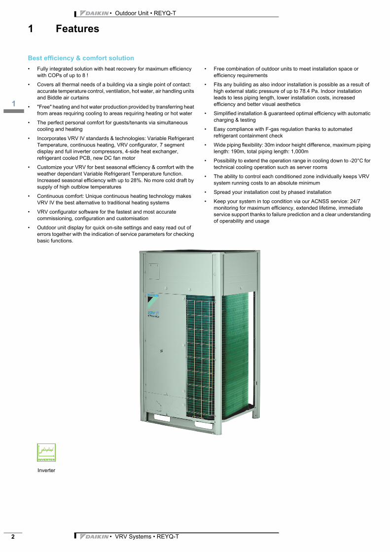
• Fully integrated solution with heat recovery for maximum efficiency with COPs of up to 8 !
• Covers all thermal needs of a building via a single point of contact: accurate temperature control, ventilation, hot water, air handling units and Biddle air curtains
• "Free" heating and hot water production provided by transferring heat from areas requiring cooling to areas requiring heating or hot water
• The perfect personal comfort for guests/tenants via simultaneous cooling and heating
• Incorporates VRV IV standards & technologies: Variable Refrigerant Temperature, continuous heating, VRV configurator, 7 segment display and full inverter compressors, 4-side heat exchanger, refrigerant cooled PCB, new DC fan motor
• Customize your VRV for best seasonal efficiency & comfort with the weather dependant Variable Refrigerant Temperature function. Increased seasonal efficiency with up to 28%. No more cold draft by supply of high outblow temperatures
• Continuous comfort: Unique continuous heating technology makes VRV IV the best alternative to traditional heating systems
• VRV configurator software for the fastest and most accurate commissioning, configuration and customisation
• Outdoor unit display for quick on-site settings and easy read out of errors together with the indication of service parameters for checking basic functions.
• Free combination of outdoor units to meet installation space or efficiency requirements
• Fits any building as also indoor installation is possible as a result of high external static pressure of up to 78.4 Pa. Indoor installation leads to less piping length, lower installation costs, increased efficiency and better visual aesthetics
• Simplified installation & guaranteed optimal efficiency with automatic charging & testing
• Easy compliance with F-gas regulation thanks to automated refrigerant containment check
• Wide piping flexibility: 30m indoor height difference, maximum piping length: 190m, total piping length: 1,000m
• Possibility to extend the operation range in cooling down to -20°C for technical cooling operation such as server rooms
• The ability to control each conditioned zone individually keeps VRV system running costs to an absolute minimum
• Spread your installation cost by phased installation
• Keep your system in top condition via our ACNSS service: 24/7 monitoring for maximum efficiency, extended lifetime, immediate service support thanks to failure prediction and a clear understanding of operability and usage
Inverter
3
2
• VRV Systems • REYQ-T 3
• Outdoor Unit • REYQ-T
2 Specifications
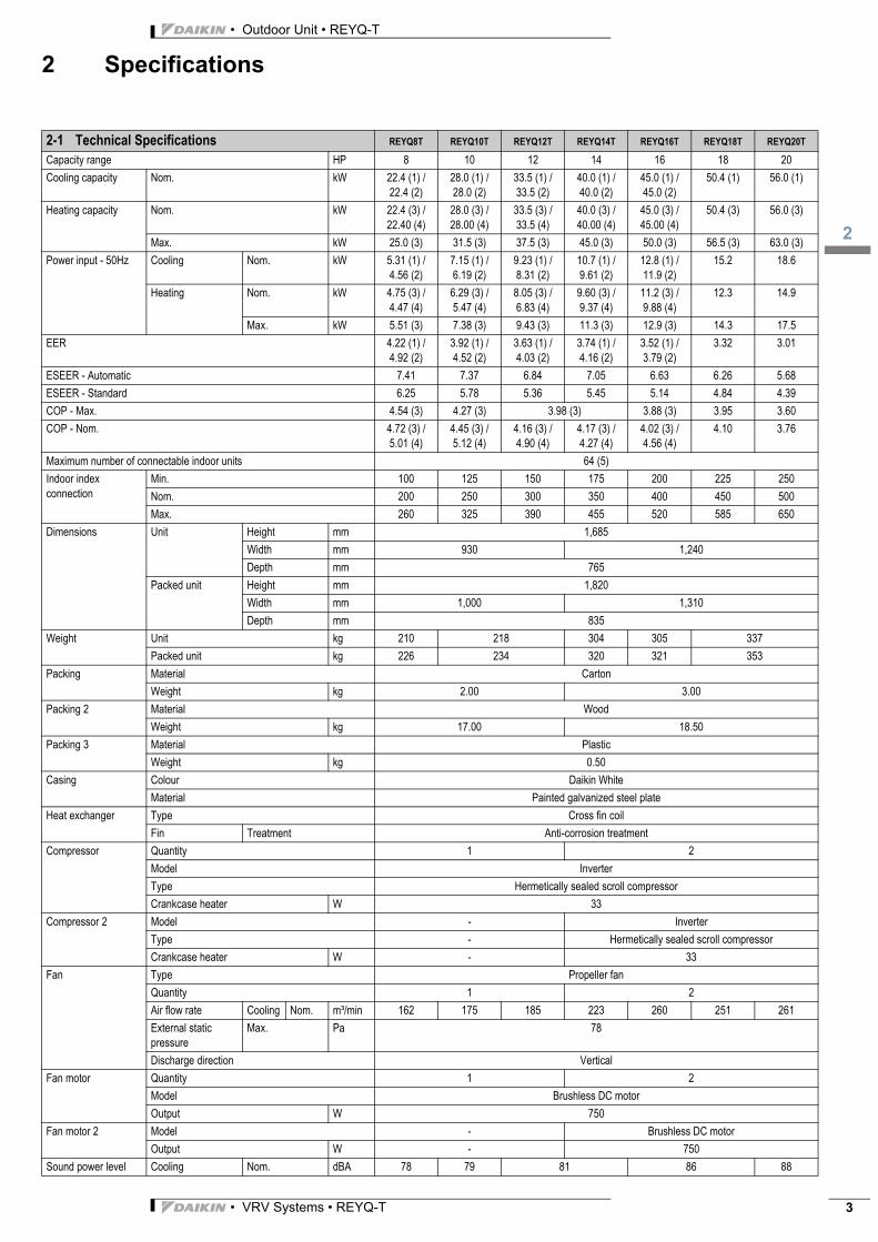
2-1 Technical Specifications REYQ8T REYQ10T REYQ12T REYQ14T REYQ16T REYQ18T REYQ20T
Capacity range HP 8 10 12 14 16 18 20
Cooling capacity Nom. kW 22.4 (1) / 22.4 (2)
28.0 (1) / 28.0 (2)
33.5 (1) / 33.5 (2)
40.0 (1) / 40.0 (2)
45.0 (1) / 45.0 (2)
50.4 (1) 56.0 (1)
Heating capacity Nom. kW 22.4 (3) / 22.40 (4)
28.0 (3) / 28.00 (4)
33.5 (3) / 33.5 (4)
40.0 (3) / 40.00 (4)
45.0 (3) / 45.00 (4)
50.4 (3) 56.0 (3)
Max. kW 25.0 (3) 31.5 (3) 37.5 (3) 45.0 (3) 50.0 (3) 56.5 (3) 63.0 (3)
Power input - 50Hz Cooling Nom. kW 5.31 (1) / 4.56 (2)
7.15 (1) / 6.19 (2)
9.23 (1) / 8.31 (2)
10.7 (1) / 9.61 (2)
12.8 (1) / 11.9 (2)
15.2 18.6
Heating Nom. kW 4.75 (3) / 4.47 (4)
6.29 (3) / 5.47 (4)
8.05 (3) / 6.83 (4)
9.60 (3) / 9.37 (4)
11.2 (3) / 9.88 (4)
12.3 14.9
Max. kW 5.51 (3) 7.38 (3) 9.43 (3) 11.3 (3) 12.9 (3) 14.3 17.5
EER 4.22 (1) / 4.92 (2)
3.92 (1) / 4.52 (2)
3.63 (1) / 4.03 (2)
3.74 (1) / 4.16 (2)
3.52 (1) / 3.79 (2)
3.32 3.01
ESEER - Automatic 7.41 7.37 6.84 7.05 6.63 6.26 5.68
ESEER - Standard 6.25 5.78 5.36 5.45 5.14 4.84 4.39
COP - Max. 4.54 (3) 4.27 (3) 3.98 (3) 3.88 (3) 3.95 3.60
COP - Nom. 4.72 (3) / 5.01 (4)
4.45 (3) / 5.12 (4)
4.16 (3) / 4.90 (4)
4.17 (3) / 4.27 (4)
4.02 (3) / 4.56 (4)
4.10 3.76
Maximum number of connectable indoor units 64 (5)
Indoor index connection
Min. 100 125 150 175 200 225 250
Nom. 200 250 300 350 400 450 500
Max. 260 325 390 455 520 585 650
Dimensions Unit Height mm 1,685
Width mm 930 1,240
Depth mm 765
Packed unit Height mm 1,820
Width mm 1,000 1,310
Depth mm 835
Weight Unit kg 210 218 304 305 337
Packed unit kg 226 234 320 321 353
Packing Material Carton
Weight kg 2.00 3.00
Packing 2 Material Wood
Weight kg 17.00 18.50
Packing 3 Material Plastic
Weight kg 0.50
Casing Colour Daikin White
Material Painted galvanized steel plate
Heat exchanger Type Cross fin coil
Fin Treatment Anti-corrosion treatment
Compressor Quantity 1 2
Model Inverter
Type Hermetically sealed scroll compressor
Crankcase heater W 33
Compressor 2 Model - Inverter
Type - Hermetically sealed scroll compressor
Crankcase heater W - 33
Fan Type Propeller fan
Quantity 1 2
Air flow rate Cooling Nom. m³/min 162 175 185 223 260 251 261
External static pressure
Max. Pa 78
Discharge direction Vertical
Fan motor Quantity 1 2
Model Brushless DC motor
Output W 750
Fan motor 2 Model - Brushless DC motor
Output W - 750
Sound power level Cooling Nom. dBA 78 79 81 86 88

• Outdoor Unit • REYQ-T
2
• VRV Systems • REYQ-T4
2 Specifications
Standard Accessories : Installation and operation manual;
Standard Accessories : Connection pipes;
Sound pressure level Cooling Nom. dBA 58 61 64 65 66
Operation range Cooling Min.~Max. °CDB -5.0~43.0
Heating Min.~Max. °CWB -20~15.5
Water production Space cooling
Min.~Max.
°CDB 10~43
Space heating
Min.~Max.
°CDB -20~20 / 24 (6)
Domestic hot water
Min.~Max.
°CDB -20~43
Refrigerant Type R-410A
Charge kg 9.7 9.8 9.9 11.8
TCO2eq 20.2 20.5 20.7 24.6
GWP 2,087.5
Refrigerant oil Type Synthetic (ether) oil
Piping connections Liquid Type Braze connection
OD mm 9.52 12.7 15.9
Gas Type Braze connection
OD mm 19.1 22.2 28.6
Discharge gas Type Braze connection
OD mm 15.9 19.1 22.2 28.6
Heat insulation Liquid, Suction gas and HP/LP gas
Piping length OU - IU Max. m 165 (7)
After branch
Max. m 90 (7)
Total piping length System Actual m 1,000 (7)
Level difference OU - IU Outdoor unit in highest position
m 90 (7)
Indoor unit in highest position
m 90 (7)
IU - IU Max. m 15
Defrost method Reversed cycle
Safety devices Item 01 High pressure switch
02 Fan driver overload protector
03 Inverter overload protector
04 PC board fuse
PED Category Category II
Most critical part Name Liquid receiver
Ps*V Bar*l 564 672 824
2-2 Electrical Specifications REYQ8T REYQ10T REYQ12T REYQ14T REYQ16T REYQ18T REYQ20T
Power supply Name Y1
Phase 3N~
Frequency Hz 50
Voltage V 380-415
Voltage range Min. % -10
Max. % 10
Current Nominal running current (RLA) - 50Hz
Cooling A 7.7 10.5 13.8 15.6 18.5 22.0 28.5
2-1 Technical Specifications REYQ8T REYQ10T REYQ12T REYQ14T REYQ16T REYQ18T REYQ20T

3
2
• VRV Systems • REYQ-T 5
• Outdoor Unit • REYQ-T
2 Specifications
Current - 50Hz Minimum Ssc value kVa 1,216 564 615 917 924 873 970
Minimum circuit amps (MCA) A 15.0 21.0 28.0 32.0 36.0 40.0
Maximum fuse amps (MFA) A 20 25 32 40 50
Total overcurrent amps (TOCA) A 17.3 21.1 35.4 42.7
Full load amps (FLA)
Total A 1.2 1.3 1.5 1.8 2.6
Wiring connections - 50Hz
For power supply Quantity 5G
For connection with indoor
Quantity 2
Remark F1,F2
Power supply intake Both indoor and outdoor unit
2-2 Electrical Specifications REYQ8T REYQ10T REYQ12T REYQ14T REYQ16T REYQ18T REYQ20T
• Outdoor Unit • REYQ-T
2
• VRV Systems • REYQ-T6
2 Specifications
Notes
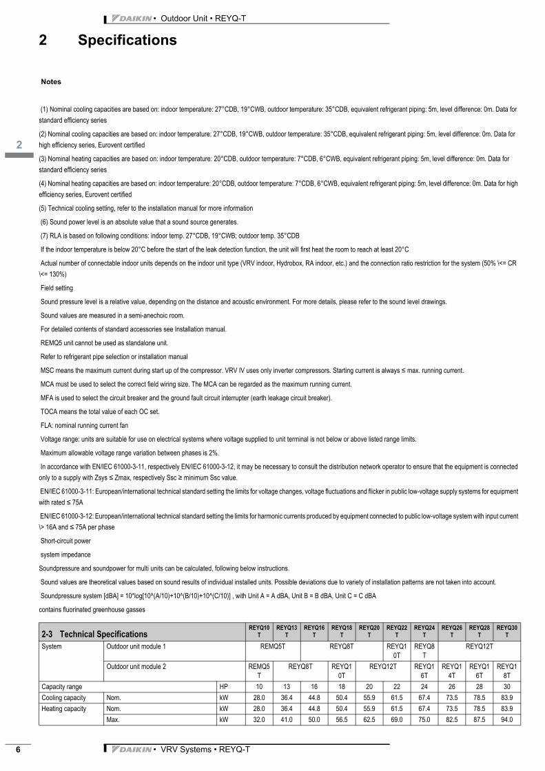
(1) Nominal cooling capacities are based on: indoor temperature: 27°CDB, 19°CWB, outdoor temperature: 35°CDB, equivalent refrigerant piping: 5m, level difference: 0m. Data for
standard efficiency series
(2) Nominal cooling capacities are based on: indoor temperature: 27°CDB, 19°CWB, outdoor temperature: 35°CDB, equivalent refrigerant piping: 5m, level difference: 0m. Data for
high efficiency series, Eurovent certified
(3) Nominal heating capacities are based on: indoor temperature: 20°CDB, outdoor temperature: 7°CDB, 6°CWB, equivalent refrigerant piping: 5m, level difference: 0m. Data for
standard efficiency series
(4) Nominal heating capacities are based on: indoor temperature: 20°CDB, outdoor temperature: 7°CDB, 6°CWB, equivalent refrigerant piping: 5m, level difference: 0m. Data for high
efficiency series, Eurovent certified
(5) Technical cooling setting, refer to the installation manual for more information
(6) Sound power level is an absolute value that a sound source generates.
(7) RLA is based on following conditions: indoor temp. 27°CDB, 19°CWB; outdoor temp. 35°CDB
If the indoor temperature is below 20°C before the start of the leak detection function, the unit will first heat the room to reach at least 20°C
Actual number of connectable indoor units depends on the indoor unit type (VRV indoor, Hydrobox, RA indoor, etc.) and the connection ratio restriction for the system (50% \<= CR
\<= 130%)
Field setting
Sound pressure level is a relative value, depending on the distance and acoustic environment. For more details, please refer to the sound level drawings.
Sound values are measured in a semi-anechoic room.
For detailed contents of standard accessories see Installation manual.
REMQ5 unit cannot be used as standalone unit.
Refer to refrigerant pipe selection or installation manual
MSC means the maximum current during start up of the compressor. VRV IV uses only inverter compressors. Starting current is always ≤ max. running current.
MCA must be used to select the correct field wiring size. The MCA can be regarded as the maximum running current.
MFA is used to select the circuit breaker and the ground fault circuit interrupter (earth leakage circuit breaker).
TOCA means the total value of each OC set.
FLA: nominal running current fan
Voltage range: units are suitable for use on electrical systems where voltage supplied to unit terminal is not below or above listed range limits.
Maximum allowable voltage range variation between phases is 2%.
In accordance with EN/IEC 61000-3-11, respectively EN/IEC 61000-3-12, it may be necessary to consult the distribution network operator to ensure that the equipment is connected
only to a supply with Zsys ≤ Zmax, respectively Ssc ≥ minimum Ssc value.
EN/IEC 61000-3-11: European/international technical standard setting the limits for voltage changes, voltage fluctuations and flicker in public low-voltage supply systems for equipment
with rated ≤ 75A
EN/IEC 61000-3-12: European/international technical standard setting the limits for harmonic currents produced by equipment connected to public low-voltage system with input current
\> 16A and ≤ 75A per phase
Short-circuit power
system impedance
Soundpressure and soundpower for multi units can be calculated, following below instructions.
Sound values are theoretical values based on sound results of individual installed units. Possible deviations due to variety of installation patterns are not taken into account.
Soundpressure system [dBA] = 10*log[10^(A/10)+10^(B/10)+10^(C/10)] , with Unit A = A dBA, Unit B = B dBA, Unit C = C dBA
contains fluorinated greenhouse gasses
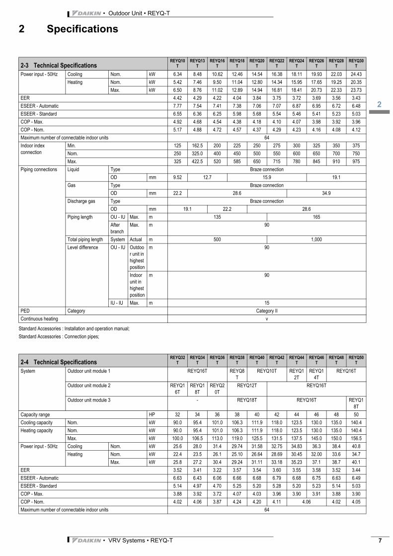
2-3 Technical SpecificationsREYQ10
TREYQ13
TREYQ16
TREYQ18
TREYQ20
TREYQ22
TREYQ24
TREYQ26
TREYQ28
TREYQ30
T
System Outdoor unit module 1 REMQ5T REYQ8T REYQ10T
REYQ8T
REYQ12T
Outdoor unit module 2 REMQ5T
REYQ8T REYQ10T
REYQ12T REYQ16T
REYQ14T
REYQ16T
REYQ18T
Capacity range HP 10 13 16 18 20 22 24 26 28 30
Cooling capacity Nom. kW 28.0 36.4 44.8 50.4 55.9 61.5 67.4 73.5 78.5 83.9
Heating capacity Nom. kW 28.0 36.4 44.8 50.4 55.9 61.5 67.4 73.5 78.5 83.9
Max. kW 32.0 41.0 50.0 56.5 62.5 69.0 75.0 82.5 87.5 94.0
3
2
• VRV Systems • REYQ-T 7
• Outdoor Unit • REYQ-T
2 Specifications
Standard Accessories : Installation and operation manual;
Standard Accessories : Connection pipes;
Power input - 50Hz Cooling Nom. kW 6.34 8.48 10.62 12.46 14.54 16.38 18.11 19.93 22.03 24.43
Heating Nom. kW 5.42 7.46 9.50 11.04 12.80 14.34 15.95 17.65 19.25 20.35
Max. kW 6.50 8.76 11.02 12.89 14.94 16.81 18.41 20.73 22.33 23.73
EER 4.42 4.29 4.22 4.04 3.84 3.75 3.72 3.69 3.56 3.43
ESEER - Automatic 7.77 7.54 7.41 7.38 7.06 7.07 6.87 6.95 6.72 6.48
ESEER - Standard 6.55 6.36 6.25 5.98 5.68 5.54 5.46 5.41 5.23 5.03
COP - Max. 4.92 4.68 4.54 4.38 4.18 4.10 4.07 3.98 3.92 3.96
COP - Nom. 5.17 4.88 4.72 4.57 4.37 4.29 4.23 4.16 4.08 4.12
Maximum number of connectable indoor units 64
Indoor index connection
Min. 125 162.5 200 225 250 275 300 325 350 375
Nom. 250 325.0 400 450 500 550 600 650 700 750
Max. 325 422.5 520 585 650 715 780 845 910 975
Piping connections Liquid Type Braze connection
OD mm 9.52 12.7 15.9 19.1
Gas Type Braze connection
OD mm 22.2 28.6 34.9
Discharge gas Type Braze connection
OD mm 19.1 22.2 28.6
Piping length OU - IU Max. m 135 165
After branch
Max. m 90
Total piping length System Actual m 500 1,000
Level difference OU - IU Outdoor unit in highest position
m 90
Indoor unit in highest position
m 90
IU - IU Max. m 15
PED Category Category II
Continuous heating v
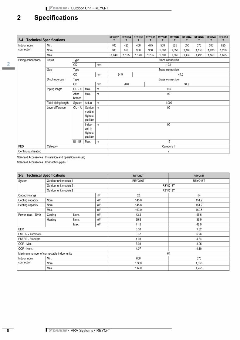
2-4 Technical SpecificationsREYQ32
TREYQ34
TREYQ36
TREYQ38
TREYQ40
TREYQ42
TREYQ44
TREYQ46
TREYQ48
TREYQ50
T
System Outdoor unit module 1 REYQ16T REYQ8T
REYQ10T REYQ12T
REYQ14T
REYQ16T
Outdoor unit module 2 REYQ16T
REYQ18T
REYQ20T
REYQ12T REYQ16T
Outdoor unit module 3 - REYQ18T REYQ16T REYQ18T
Capacity range HP 32 34 36 38 40 42 44 46 48 50
Cooling capacity Nom. kW 90.0 95.4 101.0 106.3 111.9 118.0 123.5 130.0 135.0 140.4
Heating capacity Nom. kW 90.0 95.4 101.0 106.3 111.9 118.0 123.5 130.0 135.0 140.4
Max. kW 100.0 106.5 113.0 119.0 125.5 131.5 137.5 145.0 150.0 156.5
Power input - 50Hz Cooling Nom. kW 25.6 28.0 31.4 29.74 31.58 32.75 34.83 36.3 38.4 40.8
Heating Nom. kW 22.4 23.5 26.1 25.10 26.64 28.69 30.45 32.00 33.6 34.7
Max. kW 25.8 27.2 30.4 29.24 31.11 33.18 35.23 37.1 38.7 40.1
EER 3.52 3.41 3.22 3.57 3.54 3.60 3.55 3.58 3.52 3.44
ESEER - Automatic 6.63 6.43 6.06 6.66 6.68 6.79 6.68 6.75 6.63 6.49
ESEER - Standard 5.14 4.97 4.70 5.25 5.20 5.28 5.20 5.23 5.14 5.03
COP - Max. 3.88 3.92 3.72 4.07 4.03 3.96 3.90 3.91 3.88 3.90
COP - Nom. 4.02 4.06 3.87 4.24 4.20 4.11 4.06 4.02 4.05
Maximum number of connectable indoor units 64
2-3 Technical SpecificationsREYQ10
TREYQ13
TREYQ16
TREYQ18
TREYQ20
TREYQ22
TREYQ24
TREYQ26
TREYQ28
TREYQ30
T
• Outdoor Unit • REYQ-T
2
• VRV Systems • REYQ-T8
2 Specifications
Standard Accessories : Installation and operation manual;
Standard Accessories : Connection pipes;
Indoor index connection
Min. 400 425 450 475 500 525 550 575 600 625
Nom. 800 850 900 950 1,000 1,050 1,100 1,150 1,200 1,250
Max. 1,040 1,105 1,170 1,235 1,300 1,365 1,430 1,495 1,560 1,625
Piping connections Liquid Type Braze connection
OD mm 19.1
Gas Type Braze connection
OD mm 34.9 41.3
Discharge gas Type Braze connection
OD mm 28.6 34.9
Piping length OU - IU Max. m 165
After branch
Max. m 90
Total piping length System Actual m 1,000
Level difference OU - IU Outdoor unit in highest position
m 90
Indoor unit in highest position
m 90
IU - IU Max. m 15
PED Category Category II
Continuous heating v
2-5 Technical Specifications REYQ52T REYQ54T
System Outdoor unit module 1 REYQ16T REYQ18T
Outdoor unit module 2 REYQ18T
Outdoor unit module 3 REYQ18T
Capacity range HP 52 54
Cooling capacity Nom. kW 145.8 151.2
Heating capacity Nom. kW 145.8 151.2
Max. kW 163.0 169.5
Power input - 50Hz Cooling Nom. kW 43.2 45.6
Heating Nom. kW 35.8 36.9
Max. kW 41.5 42.9
EER 3.38 3.32
ESEER - Automatic 6.37 6.26
ESEER - Standard 4.93 4.84
COP - Max. 3.93 3.95
COP - Nom. 4.07 4.10
Maximum number of connectable indoor units 64
Indoor index connection
Min. 650 675
Nom. 1,300 1,350
Max. 1,690 1,755
2-4 Technical SpecificationsREYQ32
TREYQ34
TREYQ36
TREYQ38
TREYQ40
TREYQ42
TREYQ44
TREYQ46
TREYQ48
TREYQ50
T

3
2
• VRV Systems • REYQ-T 9
• Outdoor Unit • REYQ-T
2 Specifications
Standard Accessories : Installation and operation manual;
Standard Accessories : Connection pipes;
Piping connections Liquid Type Braze connection
OD mm 19.1
Gas Type Braze connection
OD mm 41.3
Discharge gas Type Braze connection
OD mm 34.9
Piping length OU - IU Max. m 165
After branch
Max. m 90
Total piping length System Actual m 1,000
Level difference OU - IU Outdoor unit in highest position
m 90
Indoor unit in highest position
m 90
IU - IU Max. m 15
PED Category Category II
Continuous heating v
2-6 Electrical SpecificationsREYQ10
TREYQ13
TREYQ16
TREYQ18
TREYQ20
TREYQ22
TREYQ24
TREYQ26
TREYQ28
TREYQ30
T
Current Nominal running current (RLA) - 50Hz
Cooling A 8.2 11.8 15.4 18.2 21.5 24.3 26.2 29.4 32.3 35.8
Current - 50Hz Minimum Ssc value kVa 2,432 1,780 1,831 1,179 2,140 1,532 1,539 1,488
Minimum circuit amps (MCA) A 30.0 36.0 42.0 47.0 49.0 53.0 57.0
Maximum fuse amps (MFA) A 40 50 63
Wiring connections - 50Hz
For power supply Quantity 5G
For connection with indoor
Quantity 2
Remark F1,F2
Power supply intake Both indoor and outdoor unit
2-7 Electrical SpecificationsREYQ32
TREYQ34
TREYQ36
TREYQ38
TREYQ40
TREYQ42
TREYQ44
TREYQ46
TREYQ48
TREYQ50
T
Current Nominal running current (RLA) - 50Hz
Cooling A 37.0 40.5 47.0 43.5 46.3 47.5 50.8 52.6 55.5 59.0
Current - 50Hz Minimum Ssc value kVa 1,848 1,797 1,894 2,704 2,052 2,412 2,463 2,765 2,772 2,721
Minimum circuit amps (MCA) A 64.0 68.0 72.0 78.0 85.0 92.0 96.0 100.0
Maximum fuse amps (MFA) A 80 100 125
Wiring connections - 50Hz
For power supply Quantity 5G
For connection with indoor
Quantity 2
Remark F1,F2
Power supply intake Both indoor and outdoor unit
2-8 Electrical Specifications REYQ52T REYQ54T
Current Nominal running current (RLA) - 50Hz
Cooling A 62.5 66.0
Current - 50Hz Minimum Ssc value kVa 2,670 2,619
Minimum circuit amps (MCA) A 104.0 108.0
Maximum fuse amps (MFA) A 125
Wiring connections - 50Hz
For power supply Quantity 5G
For connection with indoor
Quantity 2
Remark F1,F2
Power supply intake Both indoor and outdoor unit
2-5 Technical Specifications REYQ52T REYQ54T

• Outdoor Unit • REYQ-T
2
• VRV Systems • REYQ-T10
2 Specifications
Notes
Nominal cooling capacities are based on: indoor temperature: 27°CDB, 19°CWB, outdoor temperature: 35°CDB, equivalent refrigerant piping: 5m, level difference: 0m. Data for
standard efficiency series
Nominal heating capacities are based on: indoor temperature: 20°CDB, outdoor temperature: 7°CDB, 6°CWB, equivalent refrigerant piping: 5m, level difference: 0m. Data for standard
efficiency series
If the indoor temperature is below 20°C before the start of the leak detection function, the unit will first heat the room to reach at least 20°C
Actual number of connectable indoor units depends on the indoor unit type (VRV indoor, Hydrobox, RA indoor, etc.) and the connection ratio restriction for the system (50% \<= CR
\<= 130%)
Technical cooling setting, refer to the installation manual for more information
Field setting
Sound power level is an absolute value that a sound source generates.
Sound pressure level is a relative value, depending on the distance and acoustic environment. For more details, please refer to the sound level drawings.
Sound values are measured in a semi-anechoic room.
For detailed contents of standard accessories see Installation manual.
REMQ5 unit cannot be used as standalone unit.
Refer to refrigerant pipe selection or installation manual
RLA is based on following conditions: indoor temp. 27°CDB, 19°CWB; outdoor temp. 35°CDB
MSC means the maximum current during start up of the compressor. VRV IV uses only inverter compressors. Starting current is always ≤ max. running current.
MCA must be used to select the correct field wiring size. The MCA can be regarded as the maximum running current.
MFA is used to select the circuit breaker and the ground fault circuit interrupter (earth leakage circuit breaker).
TOCA means the total value of each OC set.
FLA: nominal running current fan
Voltage range: units are suitable for use on electrical systems where voltage supplied to unit terminal is not below or above listed range limits.
Maximum allowable voltage range variation between phases is 2%.
In accordance with EN/IEC 61000-3-11, respectively EN/IEC 61000-3-12, it may be necessary to consult the distribution network operator to ensure that the equipment is connected
only to a supply with Zsys ≤ Zmax, respectively Ssc ≥ minimum Ssc value.
EN/IEC 61000-3-11: European/international technical standard setting the limits for voltage changes, voltage fluctuations and flicker in public low-voltage supply systems for equipment
with rated ≤ 75A
EN/IEC 61000-3-12: European/international technical standard setting the limits for harmonic currents produced by equipment connected to public low-voltage system with input current
\> 16A and ≤ 75A per phase
Short-circuit power
system impedance
Contains fluorinated greenhouse gases
Soundpressure and soundpower for multi units can be calculated, following below instructions.
Sound values are theoretical values based on sound results of individual installed units. Possible deviations due to variety of installation patterns are not taken into account.
Soundpressure system [dBA] = 10*log[10^(A/10)+10^(B/10)+10^(C/10)] , with Unit A = A dBA, Unit B = B dBA, Unit C = C dBA
2-9 Technical Specifications REMQ5T
Dimensions Unit Height mm 1,685
Width mm 930
Depth mm 765
Packed unit Height mm 1,820
Width mm 1,000
Depth mm 835
Weight Unit kg 210
Packed unit kg 226
Packing Material Carton
Weight kg 2.00
Packing 2 Material Wood
Weight kg 17.00

3
2
• VRV Systems • REYQ-T 11
• Outdoor Unit • REYQ-T
2 Specifications
Packing 3 Material Plastic
Weight kg 0.50
Casing Colour Daikin White
Material Painted galvanized steel plate
Heat exchanger Type Cross fin coil
Fin Treatment Anti-corrosion treatment
Compressor Quantity 1
Model Inverter
Type Hermetically sealed scroll compressor
Crankcase heater W 33
Fan Type Propeller fan
Quantity 1
Air flow rate Cooling Nom. m³/min 162
External static pressure
Max. Pa 78
Discharge direction Vertical
Fan motor Quantity 1
Model Brushless DC motor
Output W 750
Sound power level Cooling Nom. dBA 77
Sound pressure level Cooling Nom. dBA 56
Operation range Cooling Min.~Max. °CDB -5.0~43.0
Heating Min.~Max. °CWB -20~15.5
Water production Space cooling
Min.~Max.
°CDB 10~43
Space heating
Min.~Max.
°CDB -20~20 / 24 (7
Domestic hot water
Min.~Max.
°CDB -20~43
Refrigerant Type R-410A
Charge kg 9.7
TCO2eq 20.2
GWP 2,087.5
Refrigerant oil Type Synthetic (ether) oil
Piping connections Heat insulation Liquid, Suction gas and HP/LP gas
Safety devices Item 01 High pressure switch
02 Fan driver overload protector
03 Inverter overload protector
04 PC board fuse
2-10 Electrical Specifications REMQ5T
Power supply Name Y1
Phase 3N~
Frequency Hz 50
Voltage V 380-415
Voltage range Min. % -10
Max. % 10
Current Nominal running current (RLA) - 50Hz
Cooling A 4.1
Current - 50Hz Minimum Ssc value kVa 1,216
Minimum circuit amps (MCA) A 15.0
Maximum fuse amps (MFA) A 20
Total overcurrent amps (TOCA) A 17.3
Full load amps (FLA)
Total A 1.2
2-9 Technical Specifications REMQ5T

• Outdoor Unit • REYQ-T
3
• VRV Systems • REYQ-T12
3 Options3 - 1 Options
REMQ5T
REYQ-T
��������� ���� REMQ5* REYQ8* REYQ10* REYQ12* REYQ14* REYQ16* REYQ18* REYQ20* Multi ·2· Multi ·3·
������������� � � � � ������������� � � � �
����������� ���� �� ��!"�#$�%� ��!"�#$&'� � � � ��!"�#$()� � � � � � � � � ��!"�#$��� ��!"�#$�%�% ��!"�#$&'� � � � ��!"�#$()� � � � � � � � � ��*"�#�%�( � � � � � � � � ���*"�#��#)( � � � � � � � � � �+�"�� �+�"�& �+�"�) �+'"�' �+&"�' �+,"�' �+��"�' �+��"�' �+�&"�'
-���. �����/������0���������12��1�����31���2.�. +1�2���21�������4 ��+5"6-�4�����1�2���21�����������4�+5"4��7���31���2.
#. ���0����������8�����9�������.'. $1��������:�����9�������
3D088010
�������#�
$1���4�+4�1��
6;��/���������/������0����
!�<���0��2��
!�<���=��
�12��/1�������������
+��8���4�+5"4�1��

3
4
• VRV Systems • REYQ-T 13
• Outdoor Unit • REYQ-T
4 Combination table4 - 1 Combination Table
������
5 8 10 12 14 16 18 20
�
�
�
��
��
��
��
�
����������� ������� ������ � �������� �������� �������� �������� ������ � ������ � �������� � �������� �������� � ������ � � �������� � �������� � �������� � �������� � ������ � � �������� �������� � �������� � �������� � � ������ � � � �������� � �������� � �������� � �������� ������ � � �������� � �������� �
����� The ·REMQ5*· unit cannot be used as a standalone unit and may only be used in standard combinations.� Standard and free combinations have different piping restrictions.� Never combine more than ·3· units to create a multi-combination.
�� �� ��
���
����
�����
���
!"���#
$�������
��� !"���
#
%�%����&�
�'������
$�������
��� !"���
#
%�%����&�
�'������
�������������������
��� ������ �����
� � � � �
� � ������ ������ ���������
� ��������� ������ ������ ���������
� � ��������� ��������� ������
�������
�����������������������������������������
�����������������������������������������
��� �� �!��"�� �#$�"�%&'����� ��� �(��� �������������� �)!$#�$)����� �����
%&'�����*�����������+,��������-�����
������������� ./�&���,�0���� &/�&���,�0����
�������������
�������������� � �
�%&'��1����������+�������,������2������������������������
/����� �2����������������������%&'�3
���� ������ �����
./�&���,�0����
&/�&���,�0����
%&'�����
�&���,�0���������������+�������,������2�����������������������
���������

• Outdoor Unit • REYQ-T
5
• VRV Systems • REYQ-T14
5 Capacity tables5 - 1 Capacity Table Legend

3
5
• VRV Systems • REYQ-T 15
• Outdoor Unit • REYQ-T
5 Capacity tables5 - 2 Integrated Heating Capacity Correction Factor
������
��� ��� (�)�*���$�� ����������������������������� ������������������������������ ���������������������� ������ ��� �������� ��������!�����"��#
��������������� ������������������+,$�*-,$.*/ �0-�01� ��-��1� ��-��10 -� 10 �-�1� �-�1� 0-������������������������������������ � ������������ $%& $%� $'' $'( $'& $%$ �$$� $%& $%� $') $)% $'$ $'' �$$�� $%& $%� $') $)& $)* $'& �$$�� $%& $%� $'* $)� $)� $'( �$$�� $%& $%� $'* $)� $)� $'� �$$�� $%& $%� $'' $'( $'& $%$ �$$� $%& $%� $'' $'( $'& $%$ �$$� $%& $%� $'' $'( $'& $%$ �$$�� $%& $%� $'' $'( $'& $%$ �$$�� $%& $%� $'' $'( $'& $%$ �$$�� $%& $%� $'' $'� $'� $'% �$$� $%& $%� $'' $'$ $'� $'' �$$�� $%& $%� $') $)) $)' $'* �$$�� $%& $%� $') $)& $)* $'& �$$�� $%& $%� $'* $)� $)( $'( �$$�� $%& $%� $'* $)� $)( $'( �$$� $%& $%� $') $'$ $'� $'' �$$�� $%& $%� $'* $)� $)� $'� �$$�� $%& $%� $') $)' $)% $') �$$�� $%& $%� $') $)' $)% $') �$$�� $%& $%� $'' $'� $'( $'% �$$� $%& $%� $') $'$ $'� $'' �$$�� $%& $%� $'* $)� $)( $'( �$$�� $%& $%� $'* $)� $)� $'( �$$�� $%& $%� $'* $)� $)� $'� �$$�� $%& $%� $'* $)� $)� $'� �$$� $%& $%� $') $)* $)) $'* �$$�� $%& $%� $') $'$ $'� $'' �$$�� $%& $%� $'' $'( $'& $%$ �$$
����
� +��� ��������,��������������������������������� �����������������! �� ������� �����������������������-�#�
� +��� ����.�� "�������������/010(/�����������,���������������� ����.�� "��������� ����,����/�2$''$��/
3D088034
For
sin
gle
unit
inst
alla
tion
For
mul
ti-un
it in
stal
latio
n
+����������������������"������������3����������������������������������������������� � �������� ������������� �������������
+�������������������������3������� ������������������4�������������,���4��������������������������������������4�����"��������������� ����,5
6������������������� ��������� ���,�������������������������������-�������4�������,������,���"������ �������������������������������������������������������� ���������!7��2�#4������������ ������!18#���������� ������ � �������,����������

• Outdoor Unit • REYQ-T
5
• VRV Systems • REYQ-T16
5 Capacity tables5 - 3 Capacity Correction Factor
���������� � �������������������� ������-����� ���������������������������-����� .�����
���
��
������� /������������ ������������-�������������������������������-�-���� ����������������������������������+����+�0�++� �����2�����������+�������������+�0�++�4������������������������
$���5�4�����-���� � ��������������4����������� ����+������5����������������-�������������������4�������2����������,�5��������
�� $����������� � ������������-������������������������/���+�0�++���-������������������+�2� �,���������������� ���-������������������������������+�0�++���-���������������������������+���������,� �24�2�����5����� ����
�����������������������������6 !
������������������������ ����6 !
�� $���� �7���-�-����8���������
)������� �2��������+����-���������� ������2�������������������+���� �7���-�-�������+���4����������������� ������+��� �
9� :5�� ��7�5� ���� �����
6 ! "
����������������������������+������� �2������, ��
;� �0�+- ���<&=�
:5�� ��7�5� ���� �����> ��� ����+��� �6�<?�+�0�?4;�"�9?�+�6�<?�+> &�������+��� �6�<?�+�0�?4��"�9?�+�6�;@�+
��-��������������������������������������6�?�> ��� ����+��� �6�?4<@> &�������+��� �6��4?
�����
$�0�++� �5� ������������+��,��2�������������������������2���������������������-������������������������������������
�!� $�0�++� �5� ������������+��,��2�������������������������2���������������������-���������� �2����������������������
�7�5� ����-�-���� ������A+B
$�0�++���-������������������� ��-����������������������+���-��������, ������??C����������������� �����������������-�-�����������������������
$�0�++���-������������������� ��-����������������������+���-��������, ���������� ������������������� �����������������-�-�����������������������
"���# $��������#�%&���'����( ������'���#�%&���'����(<&= D�; ���E��&= �;�D �D��
:5�� ��7�5� ���� ����� �7�5� ���� �������������+����-�-� �������������� �7�5� ���� �������������,�����-�-��
"���# )����������������*������#��+��������, )����������������*���-�����+��������,F���������8� F�8��������� F���������8� F�8���������
<&= � ?�; � ?����&= � ?�; � ?�9
Main liquid pipe
80 m 40 m
Equivalent length of the branch pipe of the furthest indoor unit
.$
.$
.$
�������������������������� ������-����� ���������������������������-����� .�����
���
��
������� /������������ ������������-�������������������������������-�-���� ����������������������������������+����+�0�++� �����2�����������+�������������+�0�++�4������������������������
$���5�4�����-���� � ��������������4����������� ����+������5����������������-�������������������4�������2����������,�5��������
�� $����������� � ������������-������������������������/���+�0�++���-������������������+�2� �,���������������� ���-������������������������������+�0�++���-���������������������������+���������,� �24�2�����5����� ����
�����������������������������6 !
������������������������ ����6 !
�� $���� �7���-�-����8���������
)������� �2��������+����-���������� ������2�������������������+���� �7���-�-�������+���4����������������� ������+��� �
9� :5�� ��7�5� ���� �����
6 ! "
����������������������������+������� �2������, ��
;� �0�+- ����?&=�
:5�� ��7�5� ���� �����> ��� ����+��� �6�<?�+�0�?4;�"�9?�+�6�<?�+> &�������+��� �6�<?�+�0�?4��"�9?�+�6�;@�+
��-��������������������������������������6�?�> ��� ����+��� �6�?4<<> &�������+��� �6��4?
�����
$�0�++� �5� ������������+��,��2�������������������������2���������������������-������������������������������������
�!� $�0�++� �5� ������������+��,��2�������������������������2���������������������-���������� �2����������������������
�7�5� ����-�-���� ������A+B
$�0�++���-������������������� ��-����������������������+���-��������, ������??C����������������� �����������������-�-�����������������������
$�0�++���-������������������� ��-����������������������+���-��������, ���������� ������������������� �����������������-�-�����������������������
"���# $��������#�%&���'����( ������'���#�%&���'����(�?&= D�; ���E
:5�� ��7�5� ���� ����� �7�5� ���� �������������+����-�-� �7�5� ���� �������������,�����-�-��
"���# )����������������*������#��+��������, )����������������*���-�����+��������,F���������8� F�8��������� F���������8� F�8���������
��������������
�?&= � ?�; � ?��
Main liquid pipe
80 m 40 m
Equivalent length of the branch pipe of the furthest indoor unit
.$
.$
.$

3
5
• VRV Systems • REYQ-T 17
• Outdoor Unit • REYQ-T
5 Capacity tables5 - 3 Capacity Correction Factor
����� �������� �������������������� ������-����� ���������������������������-����� .��������� /����� �������� ��������������0�����0 �����00�
��
������� /������������ ������������-�������������������������������-�-���� ����������������������������������+����+�0�++� �����2�����������+�������������+�0�++�4������������������������
$���5�4�����-���� � ��������������4����������� ����+������5����������������-�������������������4�������2����������,�5��������
�� $����������� � ������������-������������������������/���+�0�++���-������������������+�2� �,���������������� ���-������������������������������+�0�++���-���������������������������+���������,� �24�2�����5����� ����
�����������������������������6 !
������������������������ ����6 !
�� $���� �7���-�-����8���������
)������� �2��������+����-���������� ������2�������������������+���� �7���-�-�������+���4����������������� ������+��� �
9� :5�� ��7�5� ���� �����
6 ! "
����������������������������+������� �2������, ��
;� �0�+- ����<&=�
:5�� ��7�5� ���� �����> ��� ����+��� �6�<?�+�0�?4;�"�9?�+�6�<?�+> &�������+��� �6�<?�+�0�?49�"�9?�+�6�E��+
��-��������������������������������������6�?�> ��� ����+��� �6�?4<<
> &�������+��� �6��4? �����
$�0�++� �5� ������������+��,��2�������������������������2���������������������-������������������������������������
�!� $�0�++� �5� ������������+��,��2�������������������������2���������������������-���������� �2����������������������
�7�5� ����-�-���� ������A+B
$�0�++���-������������������� ��-����������������������+���-��������, ������??C����������������� �����������������-�-�����������������������
$�0�++���-������������������� ��-����������������������+���-��������, ���������� ������������������� �����������������-�-�����������������������
"���# $��������#�%&���'����( ������'���#�%&���'����(��&= ���E �;�D�<&= �;�D �D��
�@"�<"�?"�<"9?"9�"99&= �D�� ����
:5�� ��7�5� ���� ����� �7�5� ���� �������������+����-�-� �7�5� ���� �������������,�����-�-��
"���# )����������������*������#��+��������, )����������������*���-�����+��������,F���������8� F�8��������� F���������8� F�8���������
��������������
�<"�@"�<"�?"�<"9?"9�"99&= � ?�; � ?�9��&= � ?�; � ?��
Main liquid pipe
80 m 40 m
Equivalent length of the branch pipe of the furthest indoor unit
.$
.$
.$
������������0� �������������������� ������-����� ���������������������������-����� .�����
���
��
������� /������������ ������������-�������������������������������-�-���� ����������������������������������+����+�0�++� �����2�����������+�������������+�0�++�4������������������������
$���5�4�����-���� � ��������������4����������� ����+������5����������������-�������������������4�������2����������,�5��������
�� $����������� � ������������-������������������������/���+�0�++���-������������������+�2� �,���������������� ���-������������������������������+�0�++���-���������������������������+���������,� �24�2�����5����� ����
�����������������������������6 !
������������������������ ����6 !
�� $���� �7���-�-����8���������
)������� �2��������+����-���������� ������2�������������������+���� �7���-�-�������+���4����������������� ������+��� �
9� :5�� ��7�5� ���� �����
6 ! "
����������������������������+������� �2������, ��
;� �0�+- ����9&=�
:5�� ��7�5� ���� �����> ��� ����+��� �6�<?�+�0�?4;�"�9?�+�6�<?�+> &�������+��� �6�<?�+�0�?4��"�9?�+�6�@9�+
��-��������������������������������������6�?�> ��� ����+��� �6�?4D@> &�������+��� �6��4?
�����
$�0�++� �5� ������������+��,��2�������������������������2���������������������-������������������������������������
�!� $�0�++� �5� ������������+��,��2�������������������������2���������������������-���������� �2����������������������
�7�5� ����-�-���� ������A+B
$�0�++���-������������������� ��-����������������������+���-��������, ������??C����������������� �����������������-�-�����������������������
$�0�++���-������������������� ��-����������������������+���-��������, ���������� ������������������� �����������������-�-�����������������������
"���# $��������#�%&���'����( ������'���#�%&���'����(��"�9&= ���E �;�D
:5�� ��7�5� ���� ����� �7�5� ���� �������������+����-�-� �7�5� ���� �������������,�����-�-��
"���# )����������������*������#��+��������, )����������������*���-�����+��������,F���������8� F�8��������� F���������8� F�8���������
��������������
��"�9&= � ?�; � ?��
Main liquid pipe
80 m 40 m
Equivalent length of the branch pipe of the furthest indoor unit
.$
.$
.$

• Outdoor Unit • REYQ-T
5
• VRV Systems • REYQ-T18
5 Capacity tables5 - 3 Capacity Correction Factor
�����/��������������������� ������-����� ���������������������������-����� .�����
���
��
������� /������������ ������������-�������������������������������-�-���� ����������������������������������+����+�0�++� �����2�����������+�������������+�0�++�4������������������������
$���5�4�����-���� � ��������������4����������� ����+������5����������������-�������������������4�������2����������,�5��������
�� $����������� � ������������-������������������������/���+�0�++���-������������������+�2� �,���������������� ���-������������������������������+�0�++���-���������������������������+���������,� �24�2�����5����� ����
�����������������������������6 !
������������������������ ����6 !
�� $���� �7���-�-����8���������
)������� �2��������+����-���������� ������2�������������������+���� �7���-�-�������+���4����������������� ������+��� �
9� :5�� ��7�5� ���� �����
6 ! "
����������������������������+������� �2������, ��
;� �0�+- ����@&=�
:5�� ��7�5� ���� �����> ��� ����+��� �6�<?�+�0�?4;�"�9?�+�6�<?�+> &�������+��� �6�<?�+�0�?4��"�9?�+�6�@9�+
��-��������������������������������������6�?�> ��� ����+��� �6�?4D�> &�������+��� �6��4?
�����
$�0�++� �5� ������������+��,��2�������������������������2���������������������-������������������������������������
�!� $�0�++� �5� ������������+��,��2�������������������������2���������������������-���������� �2����������������������
�7�5� ����-�-���� ������A+B
$�0�++���-������������������� ��-����������������������+���-��������, ������??C����������������� �����������������-�-�����������������������
$�0�++���-������������������� ��-����������������������+���-��������, ���������� ������������������� �����������������-�-�����������������������
"���# $��������#�%&���'����( ������'���#�%&���'����(�@&= ���E �;�D
:5�� ��7�5� ���� ����� �7�5� ���� �������������+����-�-� �7�5� ���� �������������,�����-�-��
"���# )����������������*������#��+��������, )����������������*���-�����+��������,F���������8� F�8��������� F���������8� F�8���������
��������������
�@&= � ?�; � ?��
Main liquid pipe
80 m 40 m
Equivalent length of the branch pipe of the furthest indoor unit
.$
.$
.$
���� ������ � �������������������� ������-����� ���������������������������-����� .����������0�
���
��
������� /������������ ������������-�������������������������������-�-���� ����������������������������������+����+�0�++� �����2�����������+�������������+�0�++�4������������������������
$���5�4�����-���� � ��������������4����������� ����+������5����������������-�������������������4�������2����������,�5��������
�� $����������� � ������������-������������������������/���+�0�++���-������������������+�2� �,���������������� ���-������������������������������+�0�++���-���������������������������+���������,� �24�2�����5����� ����
�����������������������������6 !
������������������������ ����6 !
�� $���� �7���-�-����8���������
)������� �2��������+����-���������� ������2�������������������+���� �7���-�-�������+���4����������������� ������+��� �
9� :5�� ��7�5� ���� �����
6 ! "
����������������������������+������� �2������, ��
;� �0�+- ����?&=�
:5�� ��7�5� ���� �����> ��� ����+��� �6�<?�+�0�?4;�"�9?�+�6�<?�+> &�������+��� �6�<?�+�0�?49�"�9?�+�6�E��+
��-��������������������������������������6�?�> ��� ����+��� �6�?4<<> &�������+��� �6��4?
�����
$�0�++� �5� ������������+��,��2�������������������������2���������������������-������������������������������������
�!� $�0�++� �5� ������������+��,��2�������������������������2���������������������-���������� �2����������������������
�7�5� ����-�-���� ������A+B
$�0�++���-������������������� ��-����������������������+���-��������, ������??C����������������� �����������������-�-�����������������������
$�0�++���-������������������� ��-����������������������+���-��������, ���������� ������������������� �����������������-�-�����������������������
"���# $��������#�%&���'����( ������'���#�%&���'����(�?&= �;�D �D��
��"�9&= �D�� ����
:5�� ��7�5� ���� ����� �7�5� ���� �������������+����-�-� �������������� �7�5� ���� �������������,�����-�-��
"���# )����������������*������#��+��������, )����������������*���-�����+��������,F���������8� F�8��������� F���������8� F�8���������
�?"��"�9&= � ?�; � ?�9
Main liquid pipe
80 m 40 m
Equivalent length of the branch pipe of the furthest indoor unit
.$
.$
.$

3
5
• VRV Systems • REYQ-T 19
• Outdoor Unit • REYQ-T
5 Capacity tables5 - 3 Capacity Correction Factor
���� 0��������������������� ������-����� ���������������������������-����� .�����
���
��
������� /������������ ������������-�������������������������������-�-���� ����������������������������������+����+�0�++� �����2�����������+�������������+�0�++�4������������������������
$���5�4�����-���� � ��������������4����������� ����+������5����������������-�������������������4�������2����������,�5��������
�� $����������� � ������������-������������������������/���+�0�++���-������������������+�2� �,���������������� ���-������������������������������+�0�++���-���������������������������+���������,� �24�2�����5����� ����
�����������������������������6 !
������������������������ ����6 !
�� $���� �7���-�-����8���������
)������� �2��������+����-���������� ������2�������������������+���� �7���-�-�������+���4����������������� ������+��� �
9� :5�� ��7�5� ���� �����
6 ! "
����������������������������+������� �2������, ��
;� �0�+- ����9&=�
:5�� ��7�5� ���� �����> ��� ����+��� �6�<?�+�0�?4;�"�9?�+�6�<?�+> &�������+��� �6�<?�+�0�?49�"�9?�+�6�E��+
��-��������������������������������������6�?�> ��� ����+��� �6�?4D�> &�������+��� �6��4?
�����
$�0�++� �5� ������������+��,��2�������������������������2���������������������-������������������������������������
�!� $�0�++� �5� ������������+��,��2�������������������������2���������������������-���������� �2����������������������
�7�5� ����-�-���� ������A+B
$�0�++���-������������������� ��-����������������������+���-��������, ������??C����������������� �����������������-�-�����������������������
$�0�++���-������������������� ��-����������������������+���-��������, ���������� ������������������� �����������������-�-�����������������������
"���# $��������#�%&���'����( ������'���#�%&���'����(�9&= �;�D �D��
:5�� ��7�5� ���� ����� �7�5� ���� �������������+����-�-� �7�5� ���� �������������,�����-�-��
"���# )����������������*������#��+��������, )����������������*���-�����+��������,F���������8� F�8��������� F���������8� F�8���������
��������������
�9&= � ?�; � ?�9
Main liquid pipe
80 m 40 m
Equivalent length of the branch pipe of the furthest indoor unit
.$
.$
.$
�����/��������������������� ������-����� ���������������������������-����� .�����
���
��
������� /������������ ������������-�������������������������������-�-���� ����������������������������������+����+�0�++� �����2�����������+�������������+�0�++�4������������������������
$���5�4�����-���� � ��������������4����������� ����+������5����������������-�������������������4�������2����������,�5��������
�� $����������� � ������������-������������������������/���+�0�++���-������������������+�2� �,���������������� ���-������������������������������+�0�++���-���������������������������+���������,� �24�2�����5����� ����
�����������������������������6 !
������������������������ ����6 !
�� $���� �7���-�-����8���������
)������� �2��������+����-���������� ������2�������������������+���� �7���-�-�������+���4����������������� ������+��� �
9� :5�� ��7�5� ���� �����
6 ! "
����������������������������+������� �2������, ��
;� �0�+- ����@&=�
:5�� ��7�5� ���� �����> ��� ����+��� �6�<?�+�0�?4;�"�9?�+�6�<?�+> &�������+��� �6�<?�+�0�?49�"�9?�+�6�E��+
��-��������������������������������������6�?�> ��� ����+��� �6�?4D�> &�������+��� �6��4?
�����
$�0�++� �5� ������������+��,��2�������������������������2���������������������-������������������������������������
�!� $�0�++� �5� ������������+��,��2�������������������������2���������������������-���������� �2����������������������
�7�5� ����-�-���� ������A+B
$�0�++���-������������������� ��-����������������������+���-��������, ������??C����������������� �����������������-�-�����������������������
$�0�++���-������������������� ��-����������������������+���-��������, ���������� ������������������� �����������������-�-�����������������������
"���# $��������#�%&���'����( ������'���#�%&���'����(�@&= �D�� ����
:5�� ��7�5� ���� ����� �7�5� ���� �������������+����-�-� �7�5� ���� �������������,�����-�-��
"���# )����������������*������#��+��������, )����������������*���-�����+��������,F���������8� F�8��������� F���������8� F�8���������
��������������
�@&= � ?�; � ?�9
Main liquid pipe
80 m 40 m
Equivalent length of the branch pipe of the furthest indoor unit
.$
.$
.$

• Outdoor Unit • REYQ-T
5
• VRV Systems • REYQ-T20
5 Capacity tables5 - 3 Capacity Correction Factor
����0/��������������������� ������-����� ���������������������������-����� .�����
���
��
������� /������������ ������������-�������������������������������-�-���� ����������������������������������+����+�0�++� �����2�����������+�������������+�0�++�4������������������������
$���5�4�����-���� � ��������������4����������� ����+������5����������������-�������������������4�������2����������,�5��������
�� $����������� � ������������-������������������������/���+�0�++���-������������������+�2� �,���������������� ���-������������������������������+�0�++���-���������������������������+���������,� �24�2�����5����� ����
�����������������������������6 !
������������������������ ����6 !
�� $���� �7���-�-����8���������
)������� �2��������+����-���������� ������2�������������������+���� �7���-�-�������+���4����������������� ������+��� �
9� :5�� ��7�5� ���� �����
6 ! "
����������������������������+������� �2������, ��
;� �0�+- ���9@&=�
:5�� ��7�5� ���� �����> ��� ����+��� �6�<?�+�0�?4;�"�9?�+�6�<?�+> &�������+��� �6�<?�+�0�?49�"�9?�+�6�E��+
��-��������������������������������������6�?�> ��� ����+��� �6�?4<<> &�������+��� �6��4?
�����
$�0�++� �5� ������������+��,��2�������������������������2���������������������-������������������������������������
�!� $�0�++� �5� ������������+��,��2�������������������������2���������������������-���������� �2����������������������
�7�5� ����-�-���� ������A+B
$�0�++���-������������������� ��-����������������������+���-��������, ������??C����������������� �����������������-�-�����������������������
$�0�++���-������������������� ��-����������������������+���-��������, ���������� ������������������� �����������������-�-�����������������������
"���# $��������#�%&���'����( ������'���#�%&���'����(9@&= �D�� ����
:5�� ��7�5� ���� ����� �7�5� ���� �������������+����-�-� �7�5� ���� �������������,�����-�-��
"���# )����������������*������#��+��������, )����������������*���-�����+��������,F���������8� F�8��������� F���������8� F�8���������
��������������
9@&= � ?�; � ?�9
Main liquid pipe
80 m 40 m
Equivalent length of the branch pipe of the furthest indoor unit
.$
.$
.$
����0������1� �������������������� ������-����� ���������������������������-����� .���������1 �����10�
���
��
������� /������������ ������������-�������������������������������-�-���� ����������������������������������+����+�0�++� �����2�����������+�������������+�0�++�4������������������������
$���5�4�����-���� � ��������������4����������� ����+������5����������������-�������������������4�������2����������,�5��������
�� $����������� � ������������-������������������������/���+�0�++���-������������������+�2� �,���������������� ���-������������������������������+�0�++���-���������������������������+���������,� �24�2�����5����� ����
�����������������������������6 !
������������������������ ����6 !
�� $���� �7���-�-����8���������
)������� �2��������+����-���������� ������2�������������������+���� �7���-�-�������+���4����������������� ������+��� �
9� :5�� ��7�5� ���� �����
6 ! "
����������������������������+������� �2������, ��
;� �0�+- ���9<&=�
:5�� ��7�5� ���� �����> ��� ����+��� �6�<?�+�0�?4;�"�9?�+�6�<?�+> &�������+��� �6�<?�+�0�?49�"�9?�+�6�E��+
��-��������������������������������������6�?�> ��� ����+��� �6�?4<<> &�������+��� �6��4?
�����
$�0�++� �5� ������������+��,��2�������������������������2���������������������-������������������������������������
�!� $�0�++� �5� ������������+��,��2�������������������������2���������������������-���������� �2����������������������
�7�5� ����-�-���� ������A+B
$�0�++���-������������������� ��-����������������������+���-��������, ������??C����������������� �����������������-�-�����������������������
$�0�++���-������������������� ��-����������������������+���-��������, ���������� ������������������� �����������������-�-�����������������������
"���# $��������#�%&���'����( ������'���#�%&���'����(9<G;9&= �D�� ����
:5�� ��7�5� ���� ����� �7�5� ���� �������������+����-�-� �7�5� ���� �������������,�����-�-��
"���# )����������������*������#��+��������, )����������������*���-�����+��������,F���������8� F�8��������� F���������8� F�8���������
��������������
9<G;9&= � ?�; � ?�9
Main liquid pipe
80 m 40 m
Equivalent length of the branch pipe of the furthest indoor unit
.$
.$
.$
3
6
• VRV Systems • REYQ-T 21
• Outdoor Unit • REYQ-T
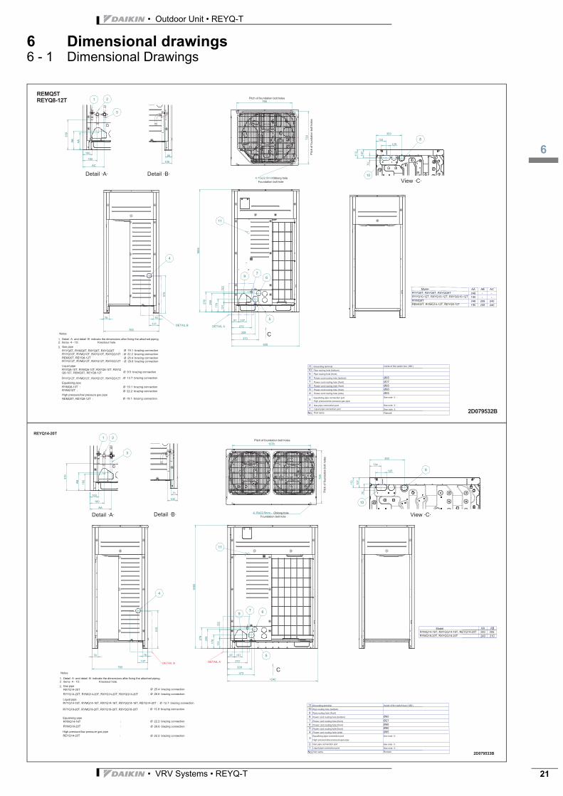
6 Dimensional drawings6 - 1 Dimensional Drawings
4
515
76
765
76
67
5
9
272
328
373
930
97 107
13117
9259
276
122
766
729
4-15x22.5mm
134
353
107
112
125
70
10
8
100
160
AA
339
AB
66
106
C
AC
240208
AB
195
248AA
REMQ5T, RYMQ10-12T, REYQ8-12TRYMQ8TRYYQ10-12T, RXYQ10-12T, RXYQQ10-12TRYYQ8T, RXYQ8T, RXYQQ8T
--195248 240208
--
137
21
3
11
1685
678910
12
3
45
Ø65Ø27Ø65Ø80Ø65
No.
11
AC
RYYQ8T, RYMQ8T, RXYQ8T, RXYQQ8T :
RYYQ12T, RYMQ12T, RXYQ12T, RXYQQ12T :
RYYQ8-10T, RYMQ8-10T, RXYQ8-10T, RXYQQ8-10T, REMQ5T, REYQ8-12T:
RYYQ10T, RYMQ10T, RXYQ10T, RXYQQ10T :
RYYQ12T, RYMQ12T, RXYQ12T, RXYQQ12T :
RYMQ8-10T :RYMQ12T :
REMQ5T, REYQ8-12T :
REMQ5T, REYQ8-12T :
1.2.
3.
DETAIL ADETAIL B
REMQ5TREYQ8-12T
2D079532B
4
67
5
9
4-15x22.5mm -
10
8
21
11
97
272
328
373
1240
107
C
13117
9259
276
122
1685
76
137
765
76
515
729
1076
134
393
107
112
125
70
106
71
192
AB
310
100
160
AA
3
ABAA
RYMQ18-20T, RXYQQ18-20TRYMQ14-16T, RXYQQ14-16T, REYQ14-20T 205240
240 210
RYYQ14-20T, RYMQ14-20T, RXYQ14-20T, RXYQQ14-20T :
RYYQ14-16T, RYMQ14-16T, RXYQ14-16T, RXYQQ14-16T, REYQ14-20T :
RYMQ14-16T :
RYMQ18-20T :
REYQ14-20T :
REYQ14-20T :
1.2.
3.
678910
12
3
45
Ø65Ø27Ø65Ø80Ø65
No.
11RYYQ18-20T, RYMQ18-20T, RXYQ18-20T, RXYQQ18-20T :
DETAIL B DETAIL A
REYQ14-20T
2D079533B
• Outdoor Unit • REYQ-T
7
• VRV Systems • REYQ-T22
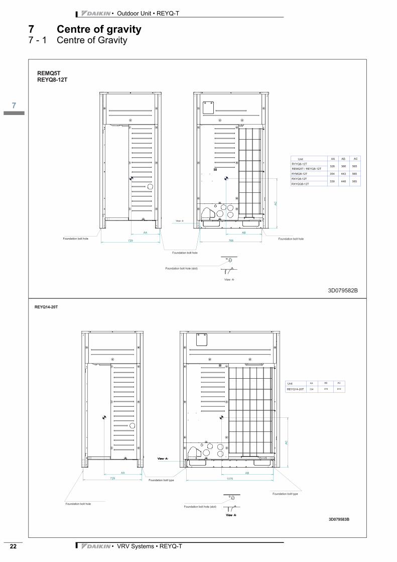
7 Centre of gravity7 - 1 Centre of Gravity
729 766
AC
AA AB AC
RYYQ8-12T
RYMQ8-12T
328
354
366
443
565
565
RXYQ8-12T339 448 565
RXYQQ8-12T
REMQ5T / REYQ8-12T
ABAA
REMQ5TREYQ8-12T
3D079582B
729 1076
AC
AA AB
REYQ14-20T
3D079583B

3
8
• VRV Systems • REYQ-T 23
• Outdoor Unit • REYQ-T
8 Piping diagrams8 - 1 Piping Diagrams
HPS
sv
Msv
M
HPS
sv
HP/LP
R7T
Y2E
R1T
R6T
R14T
R4T
R5T
R11T
R13
T
R21T
R15T
R10T R12T
S1N
PL
S1PH
S1NPH
Y3S
Y4S
Y5S
R8T
R9T
Y11S
Y5E
Y3E
Y1E
Y6EM1F
Y4E
Y2SR3T
REYQ8-12T
3D088100A
HPS
sv
M
sv
HPS
sv
Msv
M
HPSHP/LP
R7T
Y2S
Y2E
R1T
R3T
R6T
R14T
R4T
R5T
R11T
R13
T
R22T
R15T
R10T R12T
S1N
PL
S2PH
S1NPH
Y3S
Y4S
Y5S
R8T
R9T
Y11
S
Y5E
Y3E
Y1E
Y6EM1F
Y4E
Y12
S
S1PH
R21T
M2F
REYQ14-20T
3D088099A

• Outdoor Unit • REYQ-T
9
• VRV Systems • REYQ-T24
9 Wiring diagrams9 - 1 Wiring Diagrams - Single Phase
2D087541A
REMQ5T7Y1B
REYQ8T7Y1B
NOTES
1. This wiring diagram applies only to the outdoor unit.2. : Protective Earth (Screw).3. 4. 5. 6.
Power supply
A1P Printed Circuit Board (main) K13R Magnetic Relay (Y5S) (A1P) 7-Segment Display (A1P)A2P L1R Reactor Power Module (A3P) (A4P)A3P Printed Circuit Board (inv) M1C Motor (Compressor) Connector (M1F)A4P M1F Motor (Fan) X3A Connector (check the residual charge)A5P Printed Circuit Board (sub) PS Switching Power Supply (A1P) (A3P) (A5P) X1M Terminal Block (Power Supply)
Push Button Switch (A1P) Field Earth Leakage Breaker X1M Terminal Block (Control) (A1P)Phase Reversal Detect Circuit (A1P) Y1E
Capacitor (A3P) R1T Thermistor (Air) (A1P) Y2ER21T Thermistor (M1C Discharge) (A1P) Y3ER3T Thermistor (Liq. Main) (A1P) Y4ER4T Y5E
F1U R5T Y6EF101U Fuse (A4P) R6T Y11SF3U Field Fuse R7T Y2S
Fuse (A2P) R8T Y3SF400U Fuse (A2P) R9T Y4S
Pilotlamp (A1P) (A5P)(Service monitor-green)
R10T Thermistor (Suction) (A1P) Y5SR11T
K1M Magnetic Contactor (A3P) R12T Thermistor (Suction Compressor) (A5P) Z1F (With Surge Absorber)K1R Magnetic Relay (A3P) R13T
K3R Magnetic Relay (A2P) R14T Thermistor (Auto Charge) (A5P)K3R Magnetic Relay (Y11S) (A1P) R78 Resistor (Current Limiting) (A3P)K6R Magnetic Relay R24 Resistor (Current Sensor) (A4P) X10A
R77 Resistor (Current Sensor) (A3P)K7R Resistor (A3P)K9R Magnetic Relay (Y3S) (A1P)K11R Magnetic Relay (Y2S) (A1P) Pressure Sensor (Low)K12R Magnetic Relay (Y4S) (A1P)
To indoor unit To outdoor unit To multi unit
El. Compo. Box
· M1C· terminal
EL. Compo. Box
Front side Rear side

3
9
• VRV Systems • REYQ-T 25
• Outdoor Unit • REYQ-T
9 Wiring diagrams9 - 1 Wiring Diagrams - Single Phase
2D087155A
REYQ10,12T7Y1B
NOTES
1. This wiring diagram applies only to the outdoor unit.2. : Protective Earth (Screw).3. 4. 5. 6.
Power supply
A1P Printed Circuit Board (main) K13R Magnetic Relay (Y5S) (A1P)A2P Reactor 7-Segment Display (A1P)A3P Printed Circuit Board (inv) M1C Motor (Compressor) Power Module (A3P) (A4P)A4P M1F Motor (Fan) Power Module (A3P)A5P Printed Circuit Board (sub) PS Switching Power Supply (A1P) (A3P) (A5P) Connector (M1F)
Push Button Switch (A1P) Field Earth Leakage Breaker X3A Connector (check the residual charge)Phase Reversal Detect Circuit (A1P) X1M Terminal Block (Power Supply)
Capacitor (A3P) R1T Thermistor (Air) (A1P) X1M Terminal Block (Control) (A1P)R21T Thermistor (M1C Discharge) (A1P) Y1ER3T Thermistor (Liq. Main) (A1P) Y2ER4T Y3E
F1U R5T Y4EF101U Fuse (A4P) R6T Y5EF3U Field Fuse R7T Y6E
Fuse (A2P) R8T Y11SF601U Fuse (A3P) R9T Y2S
Pilotlamp (A1P) (A5P)(Service monitor-green)
R10T Thermistor (Suction) (A1P) Y3SR11T Y4S
K1M Magnetic Contactor (A3P) R12T Thermistor (Suction Compressor) (A5P) Y5SK1R Magnetic Relay (A3P) R13TK3R Magnetic Relay (A3P) R14T Thermistor (Auto Charge) (A5P) Z1F
(With Surge Absorber)K3R Magnetic Relay (Y11S) (A1P) R15T Thermistor (Compressor Body) (A1P)K6R Magnetic Relay R1 Resistor (Current Limiting) (A3P)
R24 Resistor (Current Sensor) (A4P)K7R R313 Resistor (Current Sensor) (A3P)K9R Magnetic Relay (Y3S) (A1P) Resistor (A3P) X10AK11R Magnetic Relay (Y2S) (A1P)K12R Magnetic Relay (Y4S) (A1P) Pressure Sensor (Low)
To indoor unit To outdoor unit To multi unit
El. Compo. Box
· M1C· terminal
EL. Compo. Box
Front side Rear side
• Outdoor Unit • REYQ-T
9
• VRV Systems • REYQ-T26
9 Wiring diagrams9 - 1 Wiring Diagrams - Single Phase
2D087542A
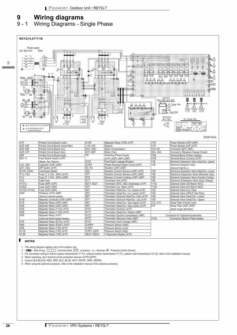
REYQ14,8T7Y1B
NOTES
1. This wiring diagram applies only to the outdoor unit.2. : Protective Earth (Screw).3. 4. 5. 6.
Power supply
A1P Printed Circuit Board (main) K13R Magnetic Relay (Y5S) (A1P) Power Module (A3P) (A6P)Reactor Power Module (A4P (A7P)
Printed Circuit Board (inv) Motor (Compressor)Motor (Fan) Connector (Residual Charge Check)
A8P Printed Circuit Board (sub) PS Switching Power Supply (A1P) (A3P) (A6P) (A8P)
X1M Terminal Block (Power Supply)Push Button Switch (A1P) X1M Terminal Block (Control) (A1P)
Field Earth Leakage Breaker Y1ECapacitor (A3P) (A6P) Phase Reversal Detect Circuit (A1P) Y2E
Resistor (A3P) (A6P)R24 Resistor (Current Sensor) (A4P) (A7P) Y3ER77 Resistor (Current Sensor) (A3P) (A6P) Y4E
F1U R78 Resistor (Current Limiting) (A3P) (A6P) Y5EF3U Field Fuse R1T Thermistor (Air) (A1P) Y6EF101U Fuse (A4P) (A7P) Y11SF400U Fuse (A2P) (A5P) R3T Thermistor (Liq. Main) (A1P) Y12S
Fuse (A2P) (A5P) R4T Y2SPilotlamp (A1P) (A8P) (Service monitor-green)
R5T Y3SR6T Y4S
K1M Magnetic Contactor (A3P) (A6P) R7T Y5SK1R Magnetic Relay (A3P) (A6P) R8TK3R Magnetic Relay (A2P) (A5P) R9T Z1F
(witch surge absorber)K3R Magnetic Relay (Y11S) (A1P) R10T Thermistor (Suction) (A1P)K4R Magnetic Relay (Y12S) (A1P) R11TK6R Magnetic Relay (A1P) R12T Thermistor (Suction compressor) (A8P)
R13T X10AK7R R14T Thermistor (Auto Charge) (A8P)K8RK9R Magnetic Relay (Y3S) (A1P) Pressure Sensor (Low)K11R Magnetic Relay (Y2S) (A1P)K12R Magnetic Relay (Y4S) (A1P) 7-Segnment Display (A1P)
To indoor unit To outdoor unit To multi unit
El. Compo. Box
EL. Compo. Box
component lead wire

3
9
• VRV Systems • REYQ-T 27
• Outdoor Unit • REYQ-T
9 Wiring diagrams9 - 1 Wiring Diagrams - Single Phase
2D087543A
REYQ18,20T7Y1B
NOTES
1. This wiring diagram applies only to the outdoor unit.2. : Protective Earth (Screw).3. 4. 5. 6.
Power supply
A1P Printed Circuit Board (main) PS Switching Power Supply (A1P) (A3P) (A6P) (A8P)
X1M Terminal Block (Power Supply)X1M Terminal Block (Control) (A1P)
Printed Circuit Board (inv) Field Earth Leakage Breaker Y1EPhase Reversal Detect Circuit (A1P) Y2E
A8P Printed Circuit Board (sub) R1 Resistor (Current Limiting) (A6P)Push Button Switch (A1P) Resistor (A3P) Y3E
R24 Resistor (Current Sensor) (A4P) (A7P) Y4ECapacitor (A3P) R77 Resistor (Current Sensor) (A3P)Capacitor (A6P) R78 Resistor (Current Limiting) (A3P) Y5E
R313 Resistor (Current Sensor) (A6P) Y6EResistor (A6P) Y11S
R1T Thermistor (Air) (A1P) Y12SF3U Field Fuse Y2SF101U Fuse (A4P) (A7P) R3T Y3SF400U Fuse (A2P) R4T Y4S
Fuse (A2P) (A5P) R5T Y5SF601U Fuse (A6P) R6T
Pilotlamp (A1P) (A8P) (Service monitor-green)
R7T Z1F (witch surge absorb)R8T
K1M Magnetic Contactor (A3P) (A6P) R9TK1R Magnetic Relay (A3P) (A6P) R10T Thermistor (Suction) (A1P)K3R Magnetic Relay (A2P) (A6P) R11T X10AK3R Magnetic Relay (Y11S) (A1P) R12T Thermistor (Suction Compressor) (A8P)K4R Magnetic Relay (Y12S) (A1P) R13TK6R Magnetic Relay (A1P) R14T Thermistor (Auto Charge) (A8P)
R15T Thermistor (Compressor Body) (A1P)K7RK8R Pressure Sensor (Low)K9R Magnetic Relay (Y3S) (A1P)K11R Magnetic Relay (Y2S) (A1P) 7-Segnment Display (A1P)K12R Magnetic Relay (Y4S) (A1P) Power Module (A3P) (A6P)K13R Magnetic Relay (Y5S) (A1P) Power Module (A4P (A7P)
Reactor Power Module (A6P)Motor (Compressor)Motor (Fan) Connector (Residual Charge Check)
To indoor unit To outdoor unit To multi unit
El. Compo. Box
EL. Compo. Box
component lead wire
• Outdoor Unit • REYQ-T
10
• VRV Systems • REYQ-T28
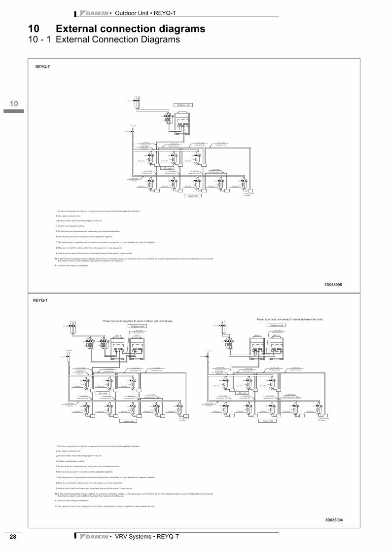
10 External connection diagrams10 - 1 External Connection Diagrams
N
L3L2
L
L1 N
NL2 L3L1
L N NLL N
L N L N L N L N L N
1.
2.
3.
4.
5.
6.
7.
8.
9.
10.
11.
REYQ-T
3D088095
L3 N
N
L2L3L2 L1
L
L1 N
L2L1 L3 N NL2 L3L1
L N NLL N
L N L N L N L N L N
NL
L N NLL N
L N L N L N L N L N
L1 NL3L2
1.
2.
3.
4.
5.
6.
7.
8.
9.
10.
11.
12.
REYQ-T
3D088094
3
10
• VRV Systems • REYQ-T 29
• Outdoor Unit • REYQ-T
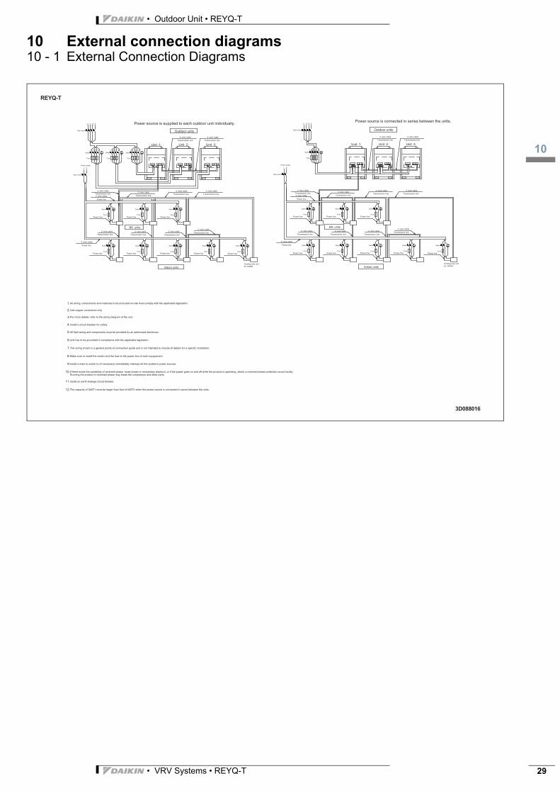
10 External connection diagrams10 - 1 External Connection Diagrams
L3 N
N
L2L3L2 L1
L
L1 N
L3 NL1 L2 L2L1 L3 N NL2 L3L1
L N NLL N
L N L N L N L N L N
NL
L N NLL N
L N L N L N L N L N
L1 NL3L2
1.
2.
3.
4.
5.
6.
7.
8.
9.
10.
11.
12.
REYQ-T
3D088016

• Outdoor Unit • REYQ-T
11
• VRV Systems • REYQ-T30
11 Sound data11 - 1 Sound Power Spectrum
REMQ5TREYQ8T
���� 5� �������.,���������������,���������!���������������������9�#� 1� ������������������������$�����/�$9.*:6; </� =���������������������>?��)(( �� 02��0*
3��"4!�5"�&��!��'!�6'!7�!��8�+9/
NR0
NR5 NR10 NR15 NR20
NR25
NR30
NR35
NR40
NR45
NR50
NR55
NR60
NR65
NR70
NR75
NR80
NR85
NR90
10
20
30
40
50
60
70
80
90
1015202530354045505560657075808590
63 125 250 500 1000 2000 4000 8000 dBA
:���&�;�<!'�=!4!=�+&*
/
REYQ10T
���� 5� �������.,���������������,���������!���������������������9�#� 1� ������������������������$�����/�$9.*:6; </� =���������������������>?��)((
�� 022 �*
3��"4!�5"�&��!��'!�6'!7�!��8�+9/
NR0
NR5 NR10 NR15 NR20
NR25
NR30
NR35
NR40
NR45
NR50
NR55
NR60
NR65
NR70
NR75
NR80
NR85
NR90
10
20
30
40
50
60
70
80
90
1015
20253035404550
55606570758085
90
63 125 250 500 1000 2000 4000 8000 dBA
:���&�;�<!'�=!4!=�+&*
/

3
11
• VRV Systems • REYQ-T 31
• Outdoor Unit • REYQ-T
11 Sound data11 - 1 Sound Power Spectrum
REYQ12T
���� 5� �������.,���������������,���������!���������������������9�#� 1� ������������������������$�����/�$9.*:6; </� =���������������������>?��)((
�� 022 2*
3��"4!�5"�&��!��'!�6'!7�!��8�+9/
NR0
NR5 NR10 NR15 NR20
NR25
NR30
NR35
NR40
NR45
NR50
NR55
NR60
NR65
NR70
NR75
NR80
NR85
NR90
10
20
30
40
50
60
70
80
90
10
15
2025
3035
40
4550
55
6065
70
7580
85
90
63 125 250 500 1000 2000 4000 8000 dBA
:���&�;�<!'�=!4!=�+&*
/
REYQ14T
���� 5� �������.,���������������,���������!���������������������9�#� 1� ������������������������$�����/�$9.*:6; </
� =���������������������>?��)(( �� 022� *
3��"4!�5"�&��!��'!�6'!7�!��8�+9/
NR0
NR5 NR10 NR15 NR20
NR25
NR30
NR35
NR40
NR45
NR50
NR55
NR60
NR65
NR70
NR75
NR80
NR85
NR90
10
20
30
40
50
60
70
80
90
10
15
20
25
30
35
40
45
50
55
60
65
70
75
80
85
90
63 125 250 500 1000 2000 4000 8000 dBA
:���&�;�<!'�=!4!=�+&*
/

• Outdoor Unit • REYQ-T
11
• VRV Systems • REYQ-T32
11 Sound data11 - 1 Sound Power Spectrum
REYQ16T
���� 5� �������.,���������������,���������!���������������������9�#� 1� ������������������������$�����/�$9.*:6; </
� =���������������������>?��)(( �� 022��*
3��"4!�5"�&��!��'!�6'!7�!��8�+9/
NR0
NR5 NR10 NR15 NR20
NR25
NR30
NR35
NR40
NR45
NR50
NR55
NR60
NR65
NR70
NR75
NR80
NR85
NR90
10
20
30
40
50
60
70
80
90
10
15
2025
30
35
4045
50
5560
65
7075
80
85
90
63 125 250 500 1000 2000 4000 8000 dBA
:���&�;�<!'�=!4!=�+&*
/
REYQ18T
���� 5� �������.,���������������,���������!���������������������9�#� 1� ������������������������$�����/�$9.*:6; </
� =���������������������>?��)(( �� 022��*
3��"4!�5"�&��!��'!�6'!7�!��8�+9/
NR0
NR5 NR10 NR15 NR20
NR25
NR30
NR35
NR40
NR45
NR50
NR55
NR60
NR65
NR70
NR75
NR80
NR85
NR90
10
20
30
40
50
60
70
80
90
10
15
20
2530
35
40
45
50
55
6065
70
75
80
85
90
63 125 250 500 1000 2000 4000 8000 dBA
:���
&�;�
<!'�=!4!=�+&*
/

3
11
• VRV Systems • REYQ-T 33
• Outdoor Unit • REYQ-T
11 Sound data11 - 1 Sound Power Spectrum
REYQ20T
���� 5� �������.,���������������,���������!���������������������9�#� 1� ������������������������$�����/�$9.*:6; </
� =���������������������>?��)(( �� 022��*
3��"4!�5"�&��!��'!�6'!7�!��8�+9/
NR0
NR5 NR10 NR15 NR20
NR25
NR30
NR35
NR40
NR45
NR50
NR55
NR60
NR65
NR70
NR75
NR80
NR85
NR90
10
20
30
40
50
60
70
80
90
10
15
20
25
30
35
40
45
50
55
60
65
70
75
80
85
90
63 125 250 500 1000 2000 4000 8000 dBA
:���&�;�<!'�=!4!=�+&*
/

• Outdoor Unit • REYQ-T
11
• VRV Systems • REYQ-T34
11 Sound data11 - 2 Sound Pressure Spectrum
REMQ5TREYQ8T
=���������������
���� 5� 2��������������� ���� ��������������� 2����������������� ������������������������� �������.,��������������������������!���������������������9�#( 1� ����������������������$�������$�:@� �� 02���*�
3��"4!�5"�&��!��'!�6'!7�!��8�+9/
NR0 NR5 NR10 NR15NR20
NR25
NR30
NR35
NR40
NR45
NR50
NR55
NR60
NR65
NR70
NR75
10
20
30
40
50
60
70
10
15
20
25
30
35
40
45
50
55
60
65
70
63 125 250 500 1000 2000 4000 8000 dBA
:���&�;'!���'!�=!4!=�+&*
/
REYQ10T
=���������������
���� 5� 2��������������� ���� ��������������� 2����������������� ������������������������� �������.,��������������������������!���������������������9�#
( 1� ����������������������$�������$�:@� 3D079902B�
3��"4!�5"�&��!��'!�6'!7�!��8�+9/
NR0 NR5 NR10 NR15NR20
NR25
NR30
NR35
NR40
NR45
NR50
NR55
NR60
NR65
NR70
NR75
10
20
30
40
50
60
70
10
15
20
25
30
35
40
45
50
55
60
65
70
62.5 125 250 500 1000 2000 4000 8000 dBA
:���
&�;'!���'!�=!4!=�+&*
/

3
11
• VRV Systems • REYQ-T 35
• Outdoor Unit • REYQ-T
11 Sound data11 - 2 Sound Pressure Spectrum
REYQ12T
=���������������
���� 5� 2��������������� ���� ��������������� 2����������������� ������������������������� �������.,��������������������������!���������������������9�#
( 1� ����������������������$�������$�:@� �� 022 �*�
:���&�;'!���'!�=!4!=�+&*
/
3��"4!�5"�&��!��'!�6'!7�!��8�+9/
NR0 NR5 NR10 NR15NR20
NR25
NR30
NR35
NR40
NR45
NR50
NR55
NR60
NR65
NR70
NR75
10
20
30
40
50
60
70
10
15
20
25
30
35
40
45
50
55
60
65
70
63 125 250 500 1000 2000 4000 8000 dBA
REYQ14T
=���������������
���� 5� 2��������������� ���� ��������������� 2����������������� ������������������������� �������.,��������������������������!���������������������9�#
( 1� ����������������������$�������$�:@� �� 022 �*�
3��"4!�5"�&��!��'!�6'!7�!��8�+9/
NR0 NR5 NR10 NR15NR20
NR25
NR30
NR35
NR40
NR45
NR50
NR55
NR60
NR65
NR70
NR75
10
20
30
40
50
60
70
10
15
20
25
30
35
40
45
50
55
60
65
70
63 125 250 500 1000 2000 4000 8000 dBA
:���&�;'!���'!�=!4!=�+&*
/

• Outdoor Unit • REYQ-T
11
• VRV Systems • REYQ-T36
11 Sound data11 - 2 Sound Pressure Spectrum
REYQ16T
=���������������
���� 5� 2��������������� ���� ��������������� 2����������������� ������������������������� �������.,��������������������������!���������������������9�#
( 1� ����������������������$�������$�:@� �� 022 �*� � �
3��"4!�5"�&��!��'!�6'!7�!��8�+9/
NR0 NR5 NR10 NR15NR20
NR25
NR30
NR35
NR40
NR45
NR50
NR55
NR60
NR65
NR70
NR75
10
20
30
40
50
60
70
10
15
20
25
30
35
40
45
50
55
60
65
70
63 125 250 500 1000 2000 4000 8000 dBA
:���
&�;'!���'!�=!4!=�+&*
/
REYQ18T
=���������������
���� 5� 2��������������� ���� ��������������� 2����������������� ������������������������� �������.,��������������������������!���������������������9�#
( 1� ����������������������$�������$�:@� �� 022 �*
3��"4!�5"�&��!��'!�6'!7�!��8�+9/
NR0 NR5 NR10 NR15NR20
NR25
NR30
NR35
NR40
NR45
NR50
NR55
NR60
NR65
NR70
NR75
10
20
30
40
50
60
70
10
15
20
25
30
35
40
45
50
55
60
65
70
63 125 250 500 1000 2000 4000 8000 dBA
:���&�;'!���'!�=!4!=�+&*
/

3
11
• VRV Systems • REYQ-T 37
• Outdoor Unit • REYQ-T
11 Sound data11 - 2 Sound Pressure Spectrum
REYQ20T
=���������������
���� 5� 2��������������� ���� ��������������� 2����������������� ������������������������� �������.,��������������������������!���������������������9�#
( 1� ����������������������$�������$�:@� �� 022 0*� � �
3��"4!�5"�&��!��'!�6'!7�!��8�+9/
NR0 NR5 NR10 NR15NR20
NR25
NR30
NR35
NR40
NR45
NR50
NR55
NR60
NR65
NR70
NR75
10
20
30
40
50
60
70
10
15
20
25
30
35
40
45
50
55
60
65
70
63 125 250 500 1000 2000 4000 8000 dBA
:���
&�;'!���'!�=!4!=�+&*
/

• Outdoor Unit • REYQ-T
12
• VRV Systems • REYQ-T38
12 Installation12 - 1 Installation Method
3D079542
REYQ-T
For single unit installation<Pattern1>
<Pattern2>
<Pattern3>
<Pattern1>
<Pattern2>
<Pattern3>
<Pattern1>
<Unit: mm>
Wall height unrestricted
Wall height unrestricted
10 or more
300 or more
500 or more<Front>
<Front>
<Front> <Front>
<Fro
nt>
<Suc
tion s
ide>
500 or more50 or more
300 or more
300 or more300 or more
10 or more 20 or more 20 or more
200 or more200 or more
100 or more
400 or more
100 or more
100 or more
For installation in rows For centralized group layout
NOTES
1. Heights of walls in case of Patterns 1 and 2:Front: 1500mmSuction side: 500mmSide: Height unrestrictedInstallation space as shown on this drawing is based on the cooling operation at 35 degrees outdoor air temperature.When the design outdoor air temperature exceeds 35 degrees or the load exceeds maximum ability because of much generation load of heat in all outdoor units, take the suction side space more broadly than the space as shown in this drawing.
2. 3.
enough space for a person to pass between units and wall and for the air to circulate freely. (If more units are to be installed than are catered for in the above patterns your layout should take account of the possibility of short circuits.)
4.
10 or more <Front>500 or more
10 or more
50 or more 50 or more 50 or more <Front>500 or more
100 or more
10 or more
400 or more
300 or more
300 or more
10 or more
10 or more 10 or more
<Front>600 or more
20 or more
20 or more<Front>500 or more
<Pattern2>
100 or more
50 or more
50 or more
<Front>500 or more
500 or more<Front>
100 or more
100 or more
50 or more
50 or more
10 or more
10 or more 20 or more
20 or more<Front>500 or more
300 or more
10 or more
10 or more
<Front>500 or more
100 or more
50 or more
100 or more
50 or more 100 or more 50 or more
100 or more 50 or more
<Front>
<Front>
10 or more
10 or more 10 or more
10 or more
500 or more
900 or more20 or more
500 or more
50 or more
50 or more 50 or more
50 or more
20 or more<Front> 500 or more
100 or more 600 or more
<Front>500 or more
100 or more

3
12
• VRV Systems • REYQ-T 39
• Outdoor Unit • REYQ-T
12 Installation12 - 2 Fixation and Foundation of Units
80
766
50100
AB
°
80
1076
929
Ø100
AD
992
729
AD
80
100
AA
AC
Floor
RYYQ8-12T
50
1302
50
RYMQ8-12TRXYQ8-12T
RYYQ14-20TRYMQ14-20TRXYQ14-20T
AA AA
AA
AB
497 697RXYCQ8
792 992RXYCQ10-14
1102 1302RXYCQ16-20
AC AD
113 185
100 160
RXYQQ8-12T
RXYQQ14-20T
REMQ5T / REYQ8-12T
REYQ14-20T
1.
2.
3.
4.
5.
REMQ5TREYQ-T
3D079547D
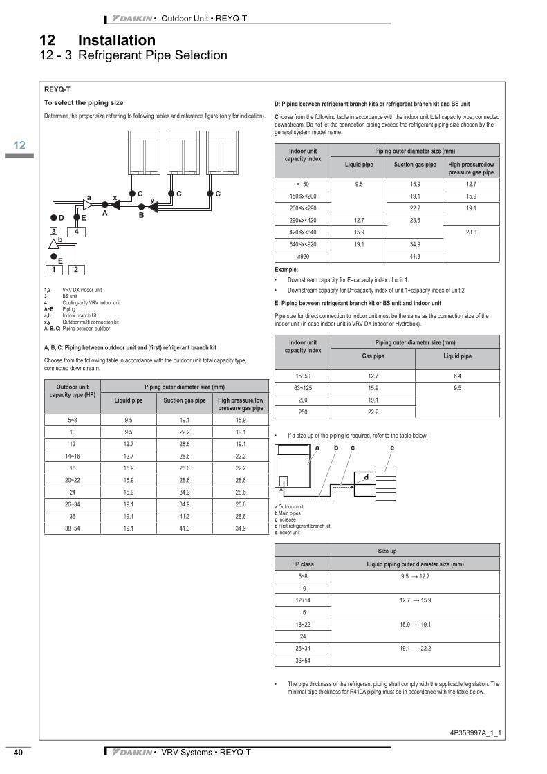
• Outdoor Unit • REYQ-T
12
• VRV Systems • REYQ-T40
12 Installation12 - 3 Refrigerant Pipe Selection
4P35399
To select the piping size
1,234 A~E Pipinga,b Indoor branch kitx,y A, B, C:
Outdoor unit
Liquid pipe
5~8
10
12
18
20~22
24
38~54
C
Indoor unit
Liquid pipe
<150
Indoor unit
Liquid pipe
15~50
200
250
ab Main pipes
Increased First refrigerant branch kite
5~8
10
18~22
24
REYQ-T

3
12
• VRV Systems • REYQ-T 41
• Outdoor Unit • REYQ-T
12 Installation12 - 3 Refrigerant Pipe Selection
4P35399 -1 _2
Pipe Ø (mm) Minimal thickness t (mm)
6.4/9.5/12.7 0.80
15.9 0.99
19.1/22.2 0.80
28.6 0.99
34.9 1.21
41.3 1.43
To select refrigerant branch kits
Refrigerant refnets
Outdoor unit capacity type (HP)
3 pipes
8~10 KHRQ23M29T9
12~22 KHRQ23M64T
24~54 KHRQ23M75T
Indoor unit capacity index 3 pipes
<200 KHRQ23M20T
KHRQ23M29T9
KHRQ23M64T
KHRQ23M75T
Indoor unit capacity index 3 pipes
<200 KHRQ23M29H
KHRQ23M75H
INFORMATION
Number of outdoor units Branch kit name
2 BHFQ23P907
3 BHFQ23P1357
About the piping length
Term
Equivalent length of the piping accessories
Accessory Equivalent length (m)
0.5
1
4
6
4
Allowable height difference
Term Height difference (m)
H1
H2 15
H3 5
H4 5
If Then
i
REYQ-T

• Outdoor Unit • REYQ-T
12
• VRV Systems • REYQ-T42
12 Installation12 - 3 Refrigerant Pipe Selection
4P35399 -1 _3
Single outdoor units and standard multi-outdoor-unit
combinations >20 HP
Connection with only VRV DX indoor units
a Outdoor unitb VRV DX indoor unitc Multi BS unitd BS unite VRV DX indoor unit
Pipe Maximum length (actual/equivalent)
Longest pipe from the outdoor unit or the last multi-outdoor piping branch (1+2, 1+3, 1+5)
165 m/190 m(a)
40 m/—(*)
In case of a multi-outdoor setup: longest pipe from the outdoor unit to the last multi-outdoor piping branch (4)
10 m/13 m
Total pipe length 1000 m/—
(a) If the equivalent piping length is more than 90 m, size up the main liquid piping according to “5.3.2 To select the piping size” on page 13.
(*)
An extension to up to 90 m is possible if all of the following conditions are met:1. In case of BS1Q units, the piping length between all indoor units and the nearest branch
2. In case of multi BS units, the piping length between all indoor units and the multi BS unit
3. that in contrast to multi BS units, BS1Q units are NOT considered branch kits. If the increased pipe size is larger than the pipe size of the main pipe, also increase the size of the main pipe.
4. After sizing up the liquid piping (previous condition), double its length in the calculation of the total piping length. Make sure the total piping length is within limitations.
5. The piping length difference between the nearest indoor unit to the outdoor unit and the
Connection with VRV DX indoor units and Hydrobox units
a Outdoor unitb VRV DX indoor unitc Multi BS unitd LT Hydrobox unite HT Hydrobox unit
Pipe Maximum length (actual/equivalent)
Longest pipe from the outdoor unit or the last multioutdoor piping branch (1+2, 1+3, 1+5)
135 m/160 m(a)
40 m
In case of a multioutdoor setup: longest pipe from the outdoor unit to the last multioutdoor piping branch (4)
10 m/13 m
Total pipe length 300 m/600 m(b)
(a) If the equivalent piping length is more than 90 m, size up the main liquid piping according to “5.3.2 To select the piping size” on page 13.
REYQ-T

3
12
• VRV Systems • REYQ-T 43
• Outdoor Unit • REYQ-T
12 Installation12 - 3 Refrigerant Pipe Selection
4P35399 -1 _4
Connection with VRV DX indoor units and air handling units
a Outdoor unitb VRV DX indoor unitc Multi BS unitd BS unite EKEXV kitf AHU
Pipe Maximum length (actual/equivalent)
Longest pipe from the outdoor unit or the last multi-outdoor piping branch (1+2, 1+3, 1+5)
165 m/190 m(a)
40 m/—
In case of a multioutdoor setup: longest pipe from the outdoor unit to the last multi-outdoor piping branch (4)
10 m/13 m
Total pipe length 1000 m/—
(a) If the equivalent piping length is more than 90 m, size up the main liquid piping according to “5.3.2 To select the piping size” on page 13.
outdoor-unit combinations
Connection with only VRV DX indoor units
a Outdoor unitb VRV DX indoor unitc Multi BS unitd BS unite VRV DX indoor unit
Pipe Maximum length (actual/equivalent)
Longest pipe from the outdoor unit or the last multioutdoor piping branch (1+2, 1+3, 1+5)
135 m/160 m(a)
40 m/—(*)
In case of a multi-outdoor setup: longest pipe from the outdoor unit to the last multi-outdoor piping branch (4)
10 m/13 m
Total pipe length 500 m/—
(a) If the equivalent piping length is more than 90 m, size up the main liquid piping according to “5.3.2 To select the piping size” on page 13.
(*)
An extension to up to 90 m is possible if all of the following conditions are met:1. In case of BS1Q units, the piping length between all indoor units and the nearest branch
2. In case of multi BS units, the piping length between all indoor units and the multi BS unit
3. that in contrast to multi BS units, BS1Q units are NOT considered branch kits. If the increased pipe size is larger than the pipe size of the main pipe, also increase the size of the main pipe.
4. After sizing up the liquid piping (previous condition), double its length in the calculation of the total piping length. Make sure the total piping length is within limitations.
5. The piping length difference between the nearest indoor unit to the outdoor unit and the
H3
1 2
H1
H2
H4
3
4
a
b
b
b
cd
e
d
e
f
f
5
H3
1 5
H1
H2
3 2
4
a
b b
c
d
e
e
REYQ-T

• Outdoor Unit • REYQ-T
12
• VRV Systems • REYQ-T44
12 Installation12 - 3 Refrigerant Pipe Selection
4P35399 -1 _5
Connection with VRV DX indoor units and Hydrobox units
a Outdoor unitb VRV DX indoor unitc Multi BS unitd LT Hydrobox unite HT Hydrobox unit
Pipe Maximum length (actual/equivalent)
Longest pipe from the outdoor unit or the last multioutdoor piping branch (1+2, 1+3, 1+5)
135 m/160 m(a)
40 m/—
In case of a multioutdoor setup: longest pipe from the outdoor unit to the last multioutdoor piping branch (4)
10 m/13 m
Total pipe length 300 m/500 m(b)
(a) If the equivalent piping length is more than 90 m, size up the main liquid piping according to “5.3.2 To select the piping size” on page 13.
Connection with VRV DX indoor units and air handling units
a Outdoor unitb VRV DX indoor unitc Multi BS unitd BS unite EKEXV kitf AHU
Pipe Maximum length (actual/equivalent)
Longest pipe from the outdoor unit or the last multioutdoor piping branch (1+2, 1+3, 1+5)
135 m/160 m(a)
40 m/—
In case of a multioutdoor setup: longest pipe from the outdoor unit to the last multioutdoor piping branch (4)
10 m/13 m
Total pipe length 500 m/—
(a) If the equivalent piping length is more than 90 m, size up the main liquid piping according to “5.3.2 To select the piping size” on page 13.
REYQ-T
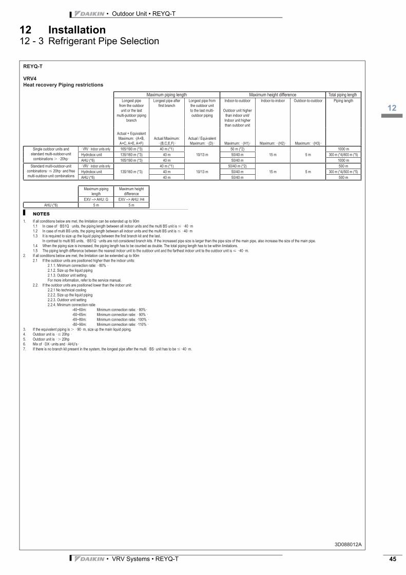
3
12
• VRV Systems • REYQ-T 45
• Outdoor Unit • REYQ-T
12 Installation12 - 3 Refrigerant Pipe Selection
3D088012A
REYQ-T
VRV4
Heat recovery Piping restrictions
Maximum piping length Maximum height difference Total piping lengthLongest pipe
from the outdoor unit or the last
multi-putdoor piping branch
Longest pipe after first branch
Longest pipe from the outdoor unit to the last multi-outdoor piping
Indoor-to-outdoor
Outdoor unit higher than indoor unit/
Indoor unit higher than outdoor unit
Indoor-to-indoor Outdoor-to-outdoor Piping length
Actual + Equivalent Maximum: ·(A+B, A+C, A+E, A+F)
Actual Maximum: · (B,C,E,F)·
Actual / Equivalent Maximum: · (D)· Maximum: · (H1)· Maximum: · (H2)· Maximum: · (H3)·
Single outdoor units and standard multi-outdoor-unit
combinations � · 20hp·
· VRV · indoor units only 165/190 m (*3) 40 m (*1)10/13 m
50 m (*2)15 m 5 m
1000 mHydrobox unit 135/160 m (*3) 40 m 50/40 m 300 m (*4)/600 m (*5)AHU (*6) 165/190 m (*3) 40 m 50/40 m 1000 m
Standard multi-outdoor-unit combinations· � 20hp· and free multi-outdoor-unit combinations
· VRV · indoor units only135/160 m (*3)
40 m (*1)10/13 m
50/40 m (*2)15 m 5 m
500 mHydrobox unit 40 m 50/40 m 300 m (*4)/500 m (*5)AHU (*6) 40 m 50/40 m 500 m
Maximum piping length
Maximum height difference
EXV --> AHU: G EXV --> AHU: H4AHU (*6) 5 m 5 m
NOTES 1. If all conditions below are met, the limitation can be extended up to 90m
1.1 In case of · BS1Q · units, the piping length between all indoor units and the multi BS unit is � · 40· m1.2 In case of multi BS units, the piping length between all indoor units and the multi BS unit is � · 40· m1.3 It is required to size up the liquid piping between the first branch kit and the last.
In contrast to multi BS units, · BS1Q · units are not considered branch kits. If the increased pipe size is larger than the pipe size of the main pipe, also increase the size of the main pipe.1.4 When the piping size is increased, the piping length has to be counted as double. The total piping length has to be within limitations.1.5 The piping length difference between the nearest indoor unit to the outdoor unit and the farthest indoor unit te the outdoor unit is � · 40· m.
2. If all conditions below are met, the limitation can be extended up to 90m2.1 If the outdoor units are positioned higher than the indoor units:
2.1.1. Minimum connection ratie: · 80% · 2.1.2. Size up the liquid piping
2.1.3. Outdoor unit setting. For more information, refer to the service manual.
2.2. If the outdoor units are positioned lower than the indoor unit: 2.2.1 No technical cooling 2.2.2. Size up the liquid piping
2.2.3. Outdoor unit setting 2.2.4. Minimum connection ratie -40~60m: Minimum connection ratie: · 80%·
-60~65m: Minimum connection ratie: · 90% · -65~80m: Minimum connection ratie: ·100% · -80~90m: Minimum connection ratie: ·110% ·
3. If the equivalent piping is � · 90· m, size up the main liquid piping.4. Outdoor unit is · � 20hp ·5. Outdoor unit is · � 20hp6. Mix of · DX· units and · AHU’s·7. If there is no branch kit present in the system, the longest pipe after the multi · BS· unit has to be �· 40· m.

• Outdoor Unit • REYQ-T
12
• VRV Systems • REYQ-T46
12 Installation12 - 3 Refrigerant Pipe Selection
3D088012A
REYQ-T
VRV4
Heat recovery Piping restrictions
Total Allowed capacityCapacity [%] Maximum indoor unit
quantityVRV indoor unit · VRV· indoor unit without
· BS· unitHydrobox unit AHU
(*1)Cooling only
(*4)· VRV· indoor units only 50~130 64 50~130 % 0~50 % Not allowed Not allowed· VRV· indoor unit + Hydrobox 50~200 (*2) 32 50~110 % 0~50 % 0~100 % Not allowed· VRV · indoor unit + · AHU’s · 50~110 64 50~110 % 0~50 % Not allowed 0~110 %
NOTES 1. Excluding · BS · units and including · EXV· kits.2. The total capacity of · DX · indoor units and LT Hydrobox units is · 130· %.3. Other combinations than mentioned in this combination table are prohibited.4. Cooling-only · VRV· indoor units cannot be combined with HT Hydrobox units.
BS1Q10 BS1Q16 BS1Q25 Multi · BS branch Multi · BS· when 2 branches are combined (*5) (*6)
(*6) (*6) (*6) (*6) (*5) (*6)· VRV· indoor units AHU
Maximum· 6· units Maximum · 100 · class
Maximum· 8· units Maximum · 160 · class
Maximum· 8· units Maximum · 250 · class
Maximum· 5· units Maximum · 140 · class
Maximum· 5· units Maximum · 250 · class
LT Hydrobox unit Maximum · 100 · class = 1x HXY080
Maximum · 160 · class = Maximum · 2 x HXY080·Or maximum · 1 x HXY125·
Maximum · 250 · class= Maximum · 3 x HXY080 ·Or maxium · 2 x HXY125 · Or · HXY125 ·
Maximum · 140 · class = Maximum · 1 x HXY080· Or maximum · 1 x HXY125·
Maximum · 250 · class = Maximum · 3 x HXY080·Or maximum · 2 x HXY125· Or · HXY080 + HXY 125 ·
NOTES 5. When combining · 2· branches, the maximum piping length between the· BS· unit and the indoor unit is � 20m. If the length of this piping is � 20m increase the size of the liquid pipe.6. When using Hydrobox units, do not combine them with other types of units.
Amount of units connectiable to a· BS· unit
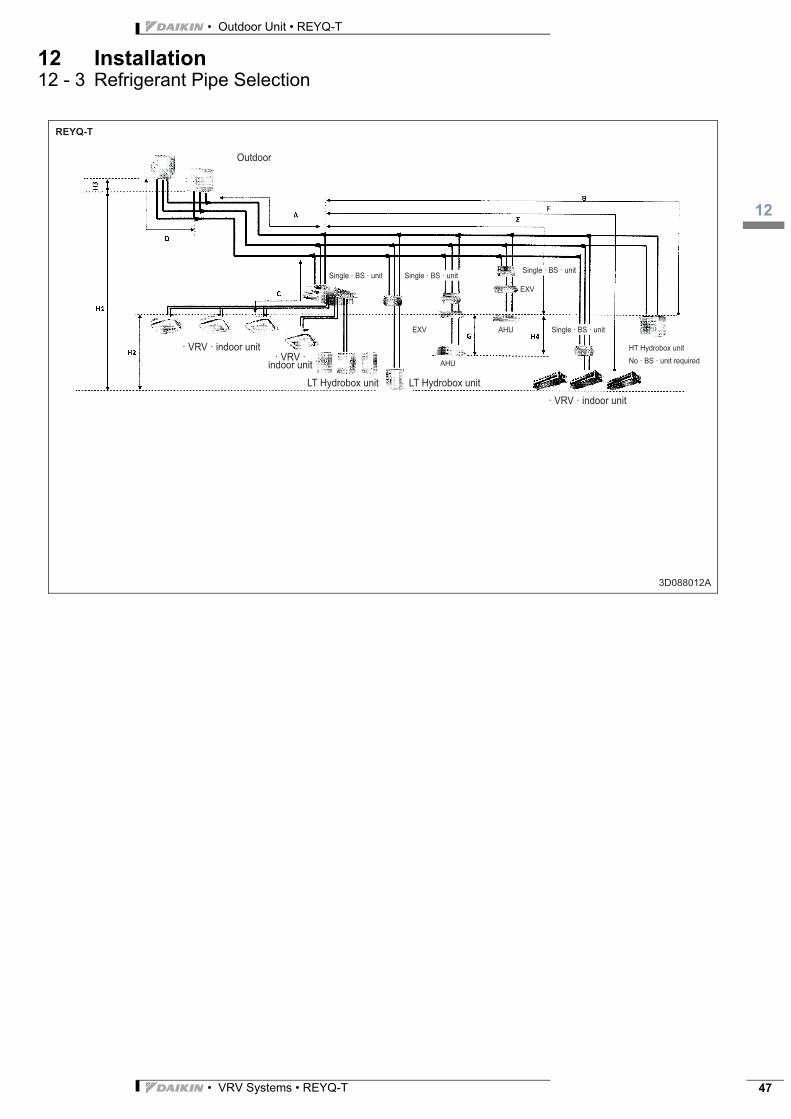
3
12
• VRV Systems • REYQ-T 47
• Outdoor Unit • REYQ-T
12 Installation12 - 3 Refrigerant Pipe Selection
3D088012A
REYQ-T
Outdoor
· VRV · indoor unit· VRV ·
indoor unit
LT Hydrobox unit LT Hydrobox unit
· VRV · indoor unit
Single · BS · unit
Single · BS · unit Single · BS · unitSingle · BS · unit
EXV
EXV AHU
HT Hydrobox unitNo · BS · unit requiredAHU

• Outdoor Unit • REYQ-T
13
• VRV Systems • REYQ-T48
13 Operation range13 - 1 Operation Range
REYQ-T
REMQ-T
3D088014
·DX· cooling
Indoor temperature [°C WB]
War
m-up
oper
ation
Pull-d
own a
rea
Pull-d
own a
rea
Outdo
or te
mper
ature
[°C
WB]
Indoor temperature [°C WB]
LWE (°C)LWT (°C)
LWT (°C)
·DX· heating
·LT hydro· cooling
·HT· space heating
·HT· domestic hot water·LT· space heatingNo domestic hot water
Technical cooling restrictions
Daikin Europe N.V. participates in the Eu-rovent Certification programme for LiquidChilling Packages (LCP), Air handling units(AHU), Fan coil units (FCU) and variable re-frigerant flow systems (VRF) Check ongo-ing validity of certificate online:www.eurovent-certification.com or using:www.certiflash.com
EE
DE
N1
5-2
00_
4
04
/15
Co
pyri
ght
Dai
kin
The
pre
sent
pu
blic
atio
n s
up
erse
des
EE
DE
N1
4-20
0_4
The present leaflet is drawn up by way of information only and does notconstitute an offer binding upon Daikin Europe N.V.. Daikin Europe N.V.has compiled the content of this leaflet to the best of its knowledge. Noexpress or implied warranty is given for the completeness, accuracy, re-liability or fitness for particular purpose of its content and the productsand services presented therein. Specifications are subject to changewithout prior notice. Daikin Europe N.V. explicitly rejects any liability forany direct or indirect damage, in the broadest sense, arising from or re-lated to the use and/or interpretation of this leaflet. All content is copy-righted by Daikin Europe N.V.
BARCODE Daikin products are distributed by:
Naamloze Vennootschap - Zandvoordestraat 300, B-8400 Oostende - Belgium - www.daikin.eu - BE 0412 120 336 - RPR Oostende