Air Conditioning Technical Data - daikintech.co.uk€¦ · 2-1 Technical Specifications UATYQ250CY1...
49
Air Conditioning Technical Data Rooftop EEDEN13-120 UATYQ-CY1
Transcript of Air Conditioning Technical Data - daikintech.co.uk€¦ · 2-1 Technical Specifications UATYQ250CY1...
Air Conditioning
Technical DataRooftop
EEDEN13-120
UATYQ-CY1

• Rooftops • Single Unit 1
• Single Unit • Rooftop • UATYQ-CY1
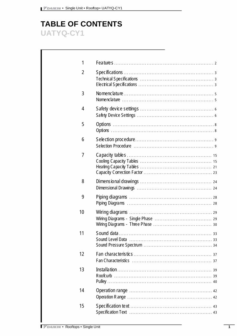
TABLE OF CONTENTSUATYQ-CY1
1 Features . . . . . . . . . . . . . . . . . . . . . . . . . . . . . . . . . . . . . . . . . . . . . . . . . . . . . . . . . . . . . 2
2 Specifications . . . . . . . . . . . . . . . . . . . . . . . . . . . . . . . . . . . . . . . . . . . . . . . . . . . . . . . 3
Technical Specifications . . . . . . . . . . . . . . . . . . . . . . . . . . . . . . . . . . . . . . . . . . . . . 3Electrical Specifications . . . . . . . . . . . . . . . . . . . . . . . . . . . . . . . . . . . . . . . . . . . . . . 3
3 Nomenclature . . . . . . . . . . . . . . . . . . . . . . . . . . . . . . . . . . . . . . . . . . . . . . . . . . . . . . . 5Nomenclature . . . . . . . . . . . . . . . . . . . . . . . . . . . . . . . . . . . . . . . . . . . . . . . . . . . . . . . . 5
4 Safety device settings . . . . . . . . . . . . . . . . . . . . . . . . . . . . . . . . . . . . . . . . . . . . . 6
Safety Device Settings . . . . . . . . . . . . . . . . . . . . . . . . . . . . . . . . . . . . . . . . . . . . . . . 6
5 Options . . . . . . . . . . . . . . . . . . . . . . . . . . . . . . . . . . . . . . . . . . . . . . . . . . . . . . . . . . . . . . 8Options . . . . . . . . . . . . . . . . . . . . . . . . . . . . . . . . . . . . . . . . . . . . . . . . . . . . . . . . . . . . . . . 8
6 Selection procedure. . . . . . . . . . . . . . . . . . . . . . . . . . . . . . . . . . . . . . . . . . . . . . . . 9
Selection Procedure . . . . . . . . . . . . . . . . . . . . . . . . . . . . . . . . . . . . . . . . . . . . . . . . . 9
7 Capacity tables . . . . . . . . . . . . . . . . . . . . . . . . . . . . . . . . . . . . . . . . . . . . . . . . . . . . 15Cooling Capacity Tables . . . . . . . . . . . . . . . . . . . . . . . . . . . . . . . . . . . . . . . . . . . . 15Heating Capacity Tables . . . . . . . . . . . . . . . . . . . . . . . . . . . . . . . . . . . . . . . . . . . . 21Capacity Correction Factor . . . . . . . . . . . . . . . . . . . . . . . . . . . . . . . . . . . . . . . . . . 23
8 Dimensional drawings . . . . . . . . . . . . . . . . . . . . . . . . . . . . . . . . . . . . . . . . . . . . 24
Dimensional Drawings . . . . . . . . . . . . . . . . . . . . . . . . . . . . . . . . . . . . . . . . . . . . . . 24
9 Piping diagrams . . . . . . . . . . . . . . . . . . . . . . . . . . . . . . . . . . . . . . . . . . . . . . . . . . . 28Piping Diagrams . . . . . . . . . . . . . . . . . . . . . . . . . . . . . . . . . . . . . . . . . . . . . . . . . . . . 28
10 Wiring diagrams . . . . . . . . . . . . . . . . . . . . . . . . . . . . . . . . . . . . . . . . . . . . . . . . . . . 29
Wiring Diagrams - Single Phase . . . . . . . . . . . . . . . . . . . . . . . . . . . . . . . . . . . 29Wiring Diagrams - Three Phase . . . . . . . . . . . . . . . . . . . . . . . . . . . . . . . . . . . . 30
11 Sound data . . . . . . . . . . . . . . . . . . . . . . . . . . . . . . . . . . . . . . . . . . . . . . . . . . . . . . . . . 33Sound Level Data . . . . . . . . . . . . . . . . . . . . . . . . . . . . . . . . . . . . . . . . . . . . . . . . . . . 33Sound Pressure Spectrum . . . . . . . . . . . . . . . . . . . . . . . . . . . . . . . . . . . . . . . . . . 34
12 Fan characteristics . . . . . . . . . . . . . . . . . . . . . . . . . . . . . . . . . . . . . . . . . . . . . . . . 37
Fan Characteristics . . . . . . . . . . . . . . . . . . . . . . . . . . . . . . . . . . . . . . . . . . . . . . . . . 37
13 Installation . . . . . . . . . . . . . . . . . . . . . . . . . . . . . . . . . . . . . . . . . . . . . . . . . . . . . . . . . . 39Roofcurb . . . . . . . . . . . . . . . . . . . . . . . . . . . . . . . . . . . . . . . . . . . . . . . . . . . . . . . . . . . . 39Pulley . . . . . . . . . . . . . . . . . . . . . . . . . . . . . . . . . . . . . . . . . . . . . . . . . . . . . . . . . . . . . . . . 40
14 Operation range . . . . . . . . . . . . . . . . . . . . . . . . . . . . . . . . . . . . . . . . . . . . . . . . . . . 42
Operation Range . . . . . . . . . . . . . . . . . . . . . . . . . . . . . . . . . . . . . . . . . . . . . . . . . . . . 42
15 Specification text . . . . . . . . . . . . . . . . . . . . . . . . . . . . . . . . . . . . . . . . . . . . . . . . . . 43Specification Text . . . . . . . . . . . . . . . . . . . . . . . . . . . . . . . . . . . . . . . . . . . . . . . . . . . 43

• Single Unit • Rooftop • UATYQ-CY1
11
2
1 Features
gle Unit ftops YQ-CY1 ftop
Sin Roo UAT Roo • Easy to install ‘plug and play’ concept plus single installat ion conf igurat ion; no additional piping is required since indoor and outdoor sides are pre-connected• High efficiency and reliable scroll compressor
• Wide operat ing range
• Flat top unit design allows maximum use of warehouse and container space
• Free cooling and fresh air intake possible with optional economiser
• Convertible return and supply air: fan can be mounted in two directions
• Factory pre-charged refrigerant ensures clean and efficient operation
• Belt driven fan enables air volume and stat ic pressure to be adjusted as required.
• Adjustable fan pulley as standard to meet a wide range of supply air volumes and external static pressures
• Anti-corrosion treated coil
• Rooftops • Single Unit
3
12
• Single Unit • Rooftop • UATYQ-CY1
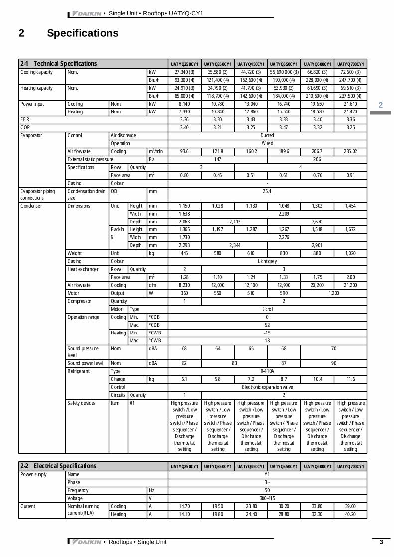
2 Specifications
2-1 Technical Specifications UATYQ25 0CY1 UATYQ35 0CY1 UA TYQ4 50CY1 UA TYQ5 50CY1 U ATYQ6 00CY1 UATYQ700CY1Cooling capacity Nom. kW 27.340 (3) 35.580 (3) 44.720 (3) 55,690.000 (3) 66.820 (3) 72.600 (3)
Btu/h 93,300 (4) 121,400 (4) 152,600 (4) 190,000 (4) 228,000 (4) 247,700 (4)Heating capacity Nom. kW 24.910 (3) 34.790 (3) 41.790 (3) 53.930 (3) 61.690 (3) 69.610 (3)
Btu/h 85,000 (4) 118,700 (4) 142,600 (4) 184,000 (4) 210,500 (4) 237,500 (4)Power input Cooling Nom. kW 8.140 10.780 13.040 16.740 19.650 21.610
Heating Nom. kW 7.330 10.840 12.860 15.540 18.580 21.420EER 3.36 3.30 3.43 3.33 3.40 3.36COP 3.40 3.21 3.25 3.47 3.32 3.25Evaporator Control Air discharge Ducted
Operation WiredAir flow rate Cooling m³/min 93.6 121.8 160.2 189.6 206.7 235.02External static pressure Pa 147 206Specifications Rows Quantity 3 4
Face area m² 0.80 0.46 0.51 0.61 0.76 0.91Casing Colour -
Evaporator piping connections
Condensation drain size
OD mm 25.4
Condenser Dimensions Unit Height mm 1,150 1,028 1,130 1,048 1,302 1,454Width mm 1,638 2,209Depth mm 2,063 2,113 2,670
Packing
Height mm 1,365 1,197 1,287 1,267 1,518 1,672Width mm 1,730 2,276Depth mm 2,293 2,344 2,901
Weight Unit kg 445 580 610 830 880 1,020Casing Colour Light greyHeat exchanger Rows Quantity 2 3
Face area m² 1.28 1.10 1.24 1.33 1.75 2.00Air flow rate Cooling cfm 8,230 12,000 12,100 12,900 20,200 21,200Motor Output W 360 550 510 590 1,200Compressor Quantity 1 2
Motor Type ScrollOperation range Cooling Min. ºCDB 0
Max. ºCDB 52Heating Min. ºCWB -15
Max. ºCWB 18Sound pressure level
Nom. dBA 68 64 65 68 70
Sound power level Nom. dBA 82 83 87 90Refrigerant Type R-410A
Charge kg 6.1 5.8 7.2 8.7 10.4 11.6Control Electronic expansion valveCircuits Quantity 1 2
Safety devices Item 01 High pressure switch / Low
pressure switch / Phase
sequencer / Discharge thermostat
setting
High pressure switch / Low
pressure switch / Phase
sequencer / Discharge thermostat
setting
High pressure switch / Low
pressure switch / Phase
sequencer / Discharge thermostat
setting
High pressure switch / Low
pressure switch / Phase
sequencer / Discharge thermostat
setting
High pressure switch / Low
pressure switch / Phase
sequencer / Discharge thermostat
setting
High pressure switch / Low
pressure switch / Phase
sequencer / Discharge thermostat
setting
2-2 Electrical Specifications UATYQ25 0CY1 UATYQ35 0CY1 UA TYQ4 50CY1 UA TYQ5 50CY1 U ATYQ6 00CY1 UATYQ700CY1Power supply Name Y1
Phase 3~Frequency Hz 50Voltage V 380-415
Cur rent Nominal running current (RLA)
Cooling A 14.70 19.50 23.80 30.20 33.80 39.00Heating A 14.10 19.80 24.40 28.80 32.30 40.20
• Rooftops • Single Unit 3

• Single Unit • Rooftop • UATYQ-CY1
12
4
2 Specifications
Notes
(1) All specifications are subjected to change by the manufacturer without pr ior notice. (2) All units are being tested and comply to ISO5151. (3) Cooling: indoor temp. 27ºCDB, 19ºCWB; outdoor temp. 35ºCDB, 24ºCWB (4) Heating: indoor temp. 20ºCDB; outdoor temp. 7ºCDB, 6ºCWB (5) Sound pressure levels are measured according to J IS B 8616 standard (6) All per formance calculations are strictly according to Eurovent standard
• Rooftops • Single Unit

3
13
• Single Unit • Rooftop • UATYQ-CY1
3 Nomenclature
3 - 1 Nomenclature• Rooftops • Single Unit 5

• Single Unit • Rooftop • UATYQ-CY1
14
6
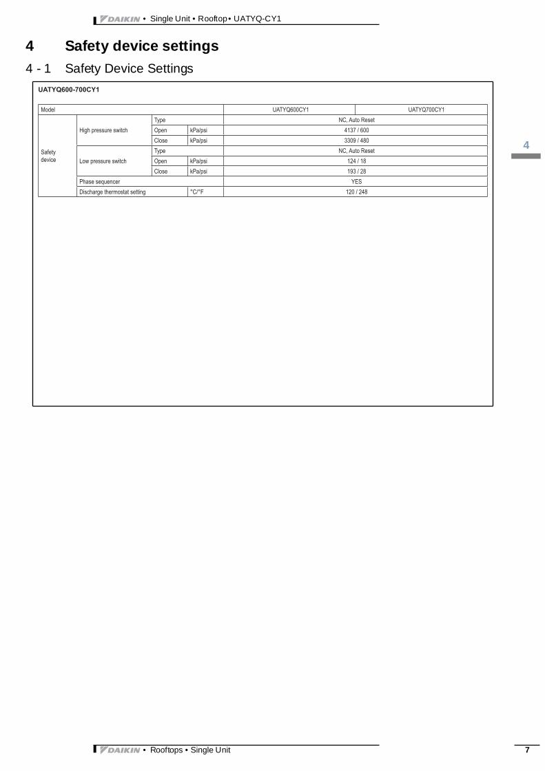
4 Safety device settings
4 - 1 Safety Device Settings• Rooftops • Single Unit
3
14
• Single Unit • Rooftop • UATYQ-CY1
4 Safety device settings
4 - 1 Safety Device Settings• Rooftops • Single Unit 7

• Single Unit • Rooftop • UATYQ-CY1
15
8
5 Options
5 - 1 Options• Rooftops • Single Unit

3
16
• Single Unit • Rooftop • UATYQ-CY1
6 Selection procedure
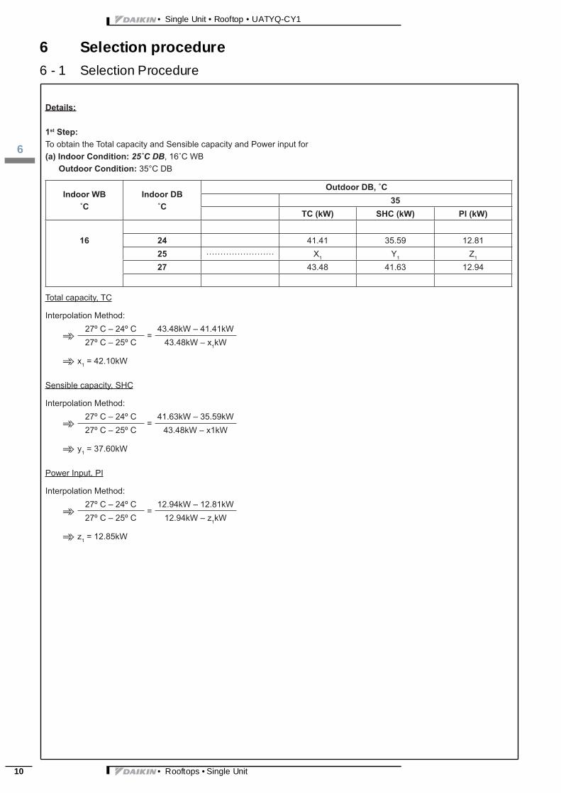
6 - 1 Selection Procedure➪ ➪
• Rooftops • Single Unit 9
• Single Unit • Rooftop • UATYQ-CY1
16
10
6 Selection procedure
6 - 1 Selection Procedure➾
➾
➾
➾
➾
➾
• Rooftops • Single Unit

3
16
• Single Unit • Rooftop • UATYQ-CY1
6 Selection procedure
6 - 1 Selection Procedure➾
➾
➾
➾
➾
➾
➾➾➾
➾➾➾
• Rooftops • Single Unit 11

• Single Unit • Rooftop • UATYQ-CY1
16
12
6 Selection procedure
6 - 1 Selection Procedure➾
➾
➾
➾
➾
➾
• Rooftops • Single Unit

3
16
• Single Unit • Rooftop • UATYQ-CY1
6 Selection procedure
6 - 1 Selection Procedure➾
➾
➾
➾
➾
➾
• Rooftops • Single Unit 13

• Single Unit • Rooftop • UATYQ-CY1
16
14
6 Selection procedure
6 - 1 Selection Procedure➾
➾
➾
➾
➾
➾
• Rooftops • Single Unit

3
17
• Single Unit • Rooftop • UATYQ-CY1
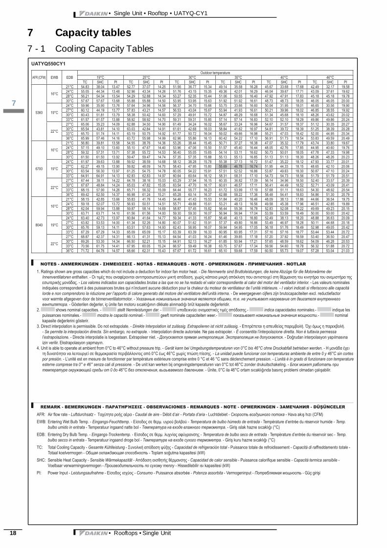
7 Capacity tables
7 - 1 Cooling Capacity Tables• Rooftops • Single Unit 15

• Single Unit • Rooftop • UATYQ-CY1
17
16
7 Capacity tables
7 - 1 Cooling Capacity Tables• Rooftops • Single Unit

3
17
• Single Unit • Rooftop • UATYQ-CY1
7 Capacity tables
7 - 1 Cooling Capacity Tables• Rooftops • Single Unit 17
• Single Unit • Rooftop • UATYQ-CY1
17
18
7 Capacity tables
7 - 1 Cooling Capacity Tables• Rooftops • Single Unit

3
17
• Single Unit • Rooftop • UATYQ-CY1
7 Capacity tables
7 - 1 Cooling Capacity Tables• Rooftops • Single Unit 19

• Single Unit • Rooftop • UATYQ-CY1
17
20
7 Capacity tables
7 - 1 Cooling Capacity Tables• Rooftops • Single Unit

3
17
• Single Unit • Rooftop • UATYQ-CY1
7 Capacity tables
7 - 2 Heating Capacity Tables• Rooftops • Single Unit 21

• Single Unit • Rooftop • UATYQ-CY1
17
22
7 Capacity tables
7 - 2 Heating Capacity Tables• Rooftops • Single Unit
3
17
• Single Unit • Rooftop • UATYQ-CY1
7 Capacity tables
7 - 3 Capacity Correction FactorPerformance Adjustment
Performance Adjustment
Pressure Drop Table
-
-
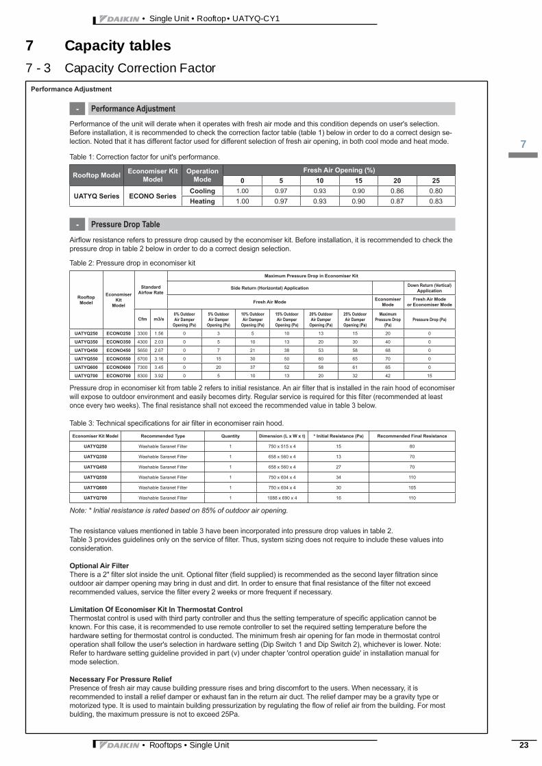
Performance of the unit will derate when it operates with fresh air mode and this condition depends on user's selection.Before installation, it is recommended to check the correction factor table (table 1) below in order to do a correct design se-lection. Noted that it has different factor used for different selection of fresh air opening, in both cool mode and heat mode.
Airflow resistance refers to pressure drop caused by the economiser kit. Before installation, it is recommended to check thepressure drop in table 2 below in order to do a correct design selection.
Pressure drop in economiser kit from table 2 refers to initial resistance. An air filter that is installed in the rain hood of economiser will expose to outdoor environment and easily becomes dirty. Regular service is required for this filter (recommended at least once every two weeks). The final resistance shall not exceed the recommended value in table 3 below.
Note: * Initial resistance is rated based on 85% of outdoor air opening.
The resistance values mentioned in table 3 have been incorporated into pressure drop values in table 2.Table 3 provides guidelines only on the service of filter. Thus, system sizing does not require to include these values intoconsideration.
Optional Air FilterThere is a 2" filter slot inside the unit. Optional fi lter (field supplied) is recommended as the second layer fi ltration sinceoutdoor air damper opening may bring in dust and dirt. In order to ensure that final resistance of the filter not exceedrecommended values, service the filter every 2 weeks or more frequent if necessary.
Limitation Of Economiser Kit In Thermostat ControlThermostat control is used with third party controller and thus the setting temperature of specific application cannot beknown. For this case, it is recommended to use remote controller to set the required setting temperature before thehardware setting for thermostat control is conducted. The minimum fresh air opening for fan mode in thermostat controloperation shall follow the user's selection in hardware setting (Dip Switch 1 and Dip Switch 2), whichever is lower. Note:Refer to hardware setting guideline provided in part (v) under chapter 'control operation guide' in installation manual formode selection.
Necessary For Pressure ReliefPresence of fresh air may cause building pressure rises and bring discomfort to the users. When necessary, it isrecommended to install a relief damper or exhaust fan in the return air duct. The relief damper may be a gravity type ormotorized type. It is used to maintain building pressurization by regulating the flow of relief air from the building. For mostbulding, the maximum pressure is not to exceed 25Pa.
Table 1: Correction factor for unit's performance.
Table 2: Pressure drop in economiser kit
Table 3: Technical specifications for air filter in economiser rain hood.
Rooftop Model Economiser Kit Model
OperationMode
Fresh Air Opening (%)0 5 10 15 20 25
UATYQ Series ECONO SeriesCooling 1.00 0.97 0.93 0.90 0.86 0.80Heating 1.00 0.97 0.93 0.90 0.87 0.83
RooftopModel
EconomiserKit
Model
StandardAirfow Rate
Maximum Pressure Drop in Economiser Kit
Side Return (Horizontal) Application Down Return (Vertical)Application
Fresh Air Mode EconomiserMode
Fresh Air Modeor Economiser Mode
Cfm m3/s0% Outdoor Air Damper
Opening (Pa)
5% Outdoor Air Damper
Opening (Pa)
10% Outdoor Air Damper
Opening (Pa)
15% Outdoor Air Damper
Opening (Pa)
20% Outdoor Air Damper
Opening (Pa)
25% Outdoor Air Damper
Opening (Pa)
MaximumPressure Drop
(Pa)Pressure Drop (Pa)
UATYQ250 ECONO250 3300 1.56 0 3 5 10 13 15 20 0
UATYQ350 ECONO350 4300 2.03 0 5 10 13 20 30 40 0
UATYQ450 ECONO450 5650 2.67 0 7 21 38 53 58 68 0
UATYQ550 ECONO550 6700 3.16 0 15 30 50 60 65 70 0
UATYQ600 ECONO600 7300 3.45 0 20 37 52 58 61 65 0
UATYQ700 ECONO700 8300 3.92 0 5 10 13 20 32 42 15
Economiser Kit Model Recommended Type Quantity Dimension (L x W x t) * Initial Resistance (Pa) Recommended Final Resistance
UATYQ250 Washable Saranet Filter 1 750 x 515 x 4 15 80
UATYQ350 Washable Saranet Filter 1 658 x 560 x 4 13 70
UATYQ450 Washable Saranet Filter 1 658 x 560 x 4 27 70
UATYQ550 Washable Saranet Filter 1 750 x 604 x 4 34 110
UATYQ600 Washable Saranet Filter 1 750 x 604 x 4 30 105
UATYQ700 Washable Saranet Filter 1 1088 x 690 x 4 16 110
• Rooftops • Single Unit 23
• Single Unit • Rooftop • UATYQ-CY1
18
24
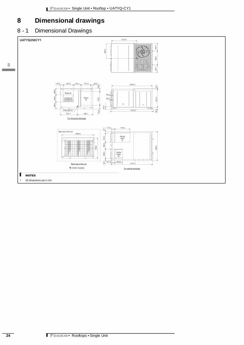
8 Dimensional drawings
8 - 1 Dimensional Drawings• Rooftops • Single Unit
3
18
• Single Unit • Rooftop • UATYQ-CY1
8 Dimensional drawings
8 - 1 Dimensional Drawings1 2
34
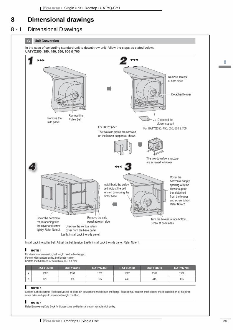
Unit ConversionG
In the case of converting standard unit to downthrow unit, follow the steps as stated below:UATYQ250, 350, 450, 550, 600 & 700
Remove screws at both sides
Detached blower
Detached the blower support
For UATYQ350, 450, 550, 600 & 700
Remove the Pulley BeltRemove the
side panelFor UATYQ250:The two side plates are screwed on the blower support as shown
The two downfl ow structureare screwed to blower
Cover the horizontal supply opening with the blower support that detached from the blower and screw tightly.Refer Note 2.
Turn the blower to face bottom.Screw at both sides.
Install back the pulley belt. Adjust the belt tension by moving the motor base.
Remove the side panel at return side
Unscrew the vertical return cover from the base panel
Install back the pulley belt. Adjust the belt tension. Lastly, install back the side panel. Refer Note 1.
Lastly, install back the side panel.
Cover the horizontal return opening with the cover and screw tightly. Refer Note 2.
NOTE 1
NOTE 1
NOTE 1
For downthrow conversion, belt length need to be changed.For unit with standard pulley, belt length = a mmShaft to shaft distance for downthrow, C-C = b mm
Sealant such like gasket (field supply) shall be placed in between the metal cover and flange. Besides that, weather-proof silicone shall be applied on all the joints, screw holes and gaps to ensure water-tight condition.
Refer Engineering Data Book for blower curve and technical data of variable pitch pulley.
UATYQ250 UATYQ350 UATYQ450 UATYQ550 UATYQ600 UATYQ700
a 1382 1357 1250 1382 1382 1382
b 375 388 375 445 445 435
• Rooftops • Single Unit 25
• Single Unit • Rooftop • UATYQ-CY1
18
26
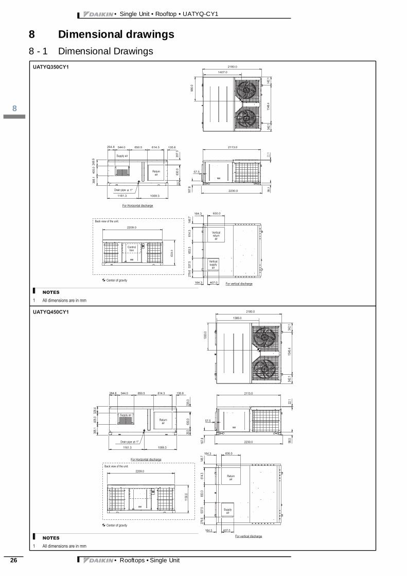
8 Dimensional drawings
8 - 1 Dimensional Drawingsø 1"
1.2431.243
4.64511.22
5.89
2113.0
2230.0
57.5
207.
3212
.763
0.0
264.8 544.0 650.5 614.3 135.6
249.
939
5.1
405.
0
1161.3 1069.3
164.3 630.0
146.
761
4.3
653.
353
7.5
279.
6
407.0164.3
2180.0
167.
898
0.0
1407.0
2209.0
0.8201
342.1
2180.0
1546
.434
2.122
.1
2113.0
98.5
57.5
167.8 2230.0
630.0164.3
407.0164.3
146.7
614.3
653.3
537.5
279.6
2209.0
1130
.0
264.8 544.0 650.5 614.3 135.6
ø 1"
235.0
630.0
263.5
1161.3 1069.3
328.4
405.0
395.1
1385.0
1000
.0
• Rooftops • Single Unit

3
18
• Single Unit • Rooftop • UATYQ-CY1
8 Dimensional drawings
8 - 1 Dimensional Drawings342.
1
2738.5
1546
.634
1.9
22.5
2670.0
98.5
47.8
167.
4
2788.5
770.0171.6
509.0 179.3
201.
461
0.0
559.
558
0.5
281.
32209.0
A
267.6 586.0 558.3 610.0 187.3
BC1161.8 1068.8
509.
040
5.2
1735.0
1000
.0
550 600 700
A 1048.0 1302.0 1454.0B 770.0 770.0 1176.0C 182.2 322.0 182.2
• Rooftops • Single Unit 27
• Single Unit • Rooftop • UATYQ-CY1
19
28
9 Piping diagrams
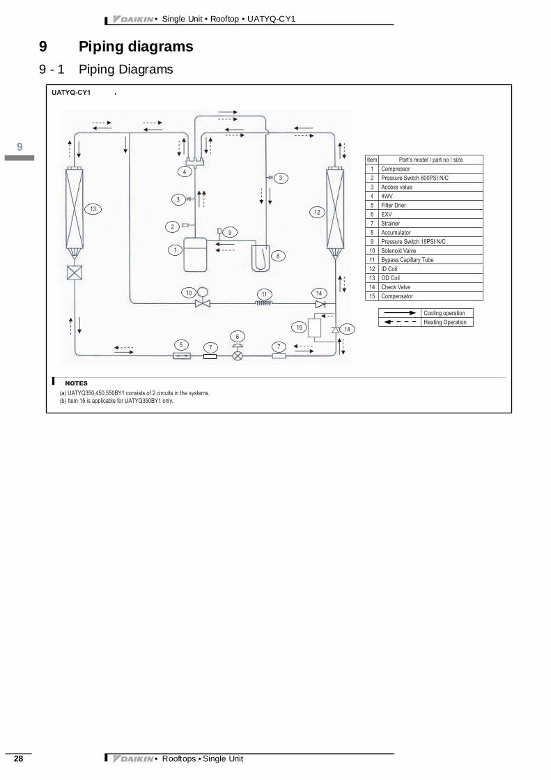
9 - 1 Piping Diagrams• Rooftops • Single Unit

3
110
• Single Unit • Rooftop • UATYQ-CY1
10 Wiring diagrams
10 - 1 Wiring Diagrams - Single Phase11
10
2
19
5
6
8
7
74 3
1110
2
19 56 8
77 44 3
11
195
6
8
7
7
4
4
2
10
Arrangement of terminal blocks and components for controller are shown as below:
Control Module UATYQ250
Control Module UATYQ600/700
Control Module UATYQ350/450/550
(Bottom Layer) (Top Layer)
NOTESItem 11 (Economiser Controller Board) shall be used together with the economiser kit which is provided separately as the accessory.
A
C
B
No. Item Description
1 Controller Main Board
2 EXV Controller Board
3 Capacitor
4 Contactor
5 Phase Protector
6 Relay
7 Terminal Block
8 Fuse
9 Transformer
10 Terminal Block Cover
11 Economiser Controller Board
• Rooftops • Single Unit 29

• Single Unit • Rooftop • UATYQ-CY1
110
30
10 Wiring diagrams
10 - 2 Wiring Diagrams - Three Phase• Rooftops • Single Unit

3
110
• Single Unit • Rooftop • UATYQ-CY1
10 Wiring diagrams
10 - 2 Wiring Diagrams - Three Phase• Rooftops • Single Unit 31
• Single Unit • Rooftop • UATYQ-CY1
110
32
10 Wiring diagrams
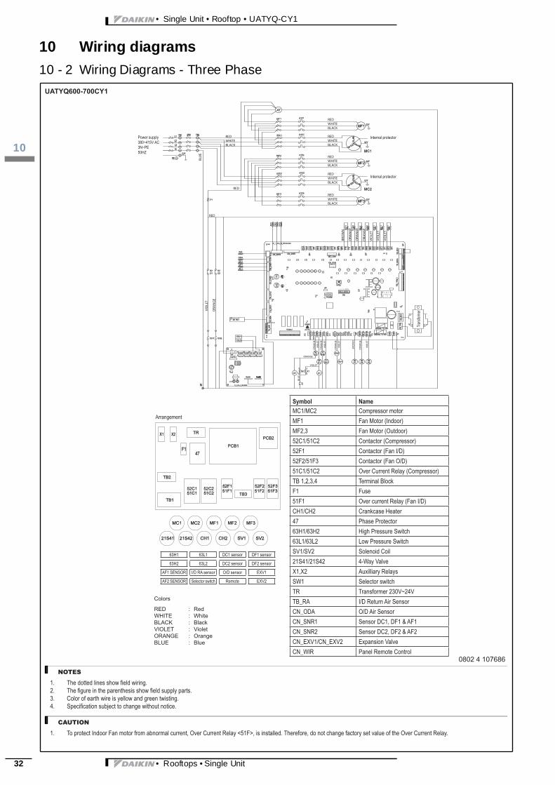
10 - 2 Wiring Diagrams - Three PhaseREDWHITEBLACK
RED
RED
REDWHITEBLACK
REDWHITEBLACK
REDWHITEBLACK
BRO
WN
VIO
LET
ORANGEO
RAN
GE
VIOLET
VIO
LET
ORA
NG
E
VIO
LET
ORA
NG
E
VIO
LET
ORA
NG
E
BLU
E
VIO
LET
ORA
NG
E
BRO
WN
ORA
NG
E
ORA
NG
E
ORA
NG
E
VIO
LET
VIO
LET
VIO
LET
REDWHITEBLACK
REDWHITEBLACK
BLU
E
• Rooftops • Single Unit

3
111
• Single Unit • Rooftop • UATYQ-CY1
11 Sound data
11 - 1 Sound Level Data• Rooftops • Single Unit 33

• Single Unit • Rooftop • UATYQ-CY1
111
34
11 Sound data
11 - 2 Sound Pressure Spectrum• Rooftops • Single Unit

3
111
• Single Unit • Rooftop • UATYQ-CY1
11 Sound data
11 - 2 Sound Pressure Spectrum• Rooftops • Single Unit 35
• Single Unit • Rooftop • UATYQ-CY1
111
36
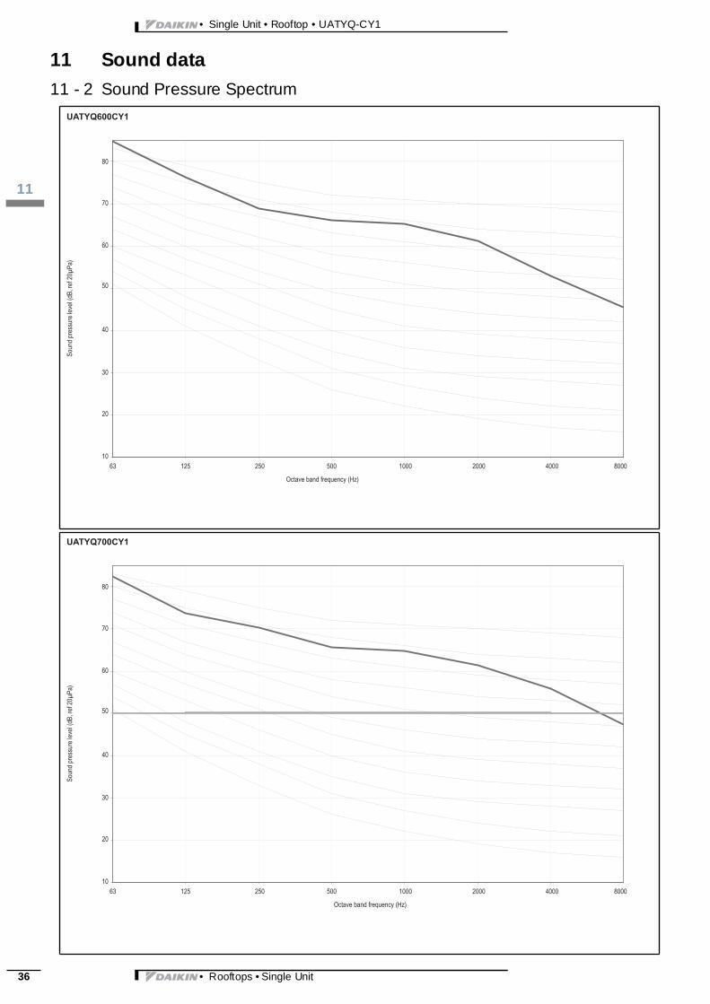
11 Sound data
11 - 2 Sound Pressure Spectrum• Rooftops • Single Unit

3
112
• Single Unit • Rooftop • UATYQ-CY1
12 Fan characteristics
12 - 1 Fan Characteristics0
2.2 kW
1.5 kW
1.1 kW
500
• Rooftops • Single Unit 37
• Single Unit • Rooftop • UATYQ-CY1
112
38
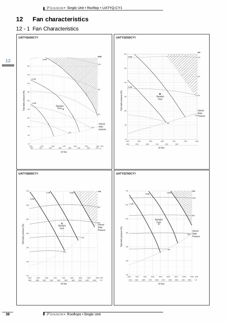
12 Fan characteristics
12 - 1 Fan Characteristics50
150
250
350
450
550
650
5300 5800 6300 6800 7300 7800 8300
700
600
2500 2700 2900 3100 3300 3500
800
900
1000
100
200
300
400
500
600
700
5500 6000 6500 7000 7500 8000 8500 9000 9500 CFM
900
800
700
600
2600 2800 3000 3200 3400 3600 3800 4000 4200 4400 L/S
150
250
350
450
550
650
750
6500 7000 7500 8000 8500 9000 9500 10000 10500 CFM
800
900
700
3100 3300 3500 3700 3900 4100 4300 4500 4700 4900 L/S
1000
• Rooftops • Single Unit

3
113
• Single Unit • Rooftop • UATYQ-CY1
13 Installation
13 - 1 RoofcurbN
300.
0 140.
0
M
B
K
LJ
IA
C
B F
C
A25
.0
E
B D
CO
P
AF
300.
0
25.0
355.
0
G
H
• Rooftops • Single Unit 39

• Single Unit • Rooftop • UATYQ-CY1
113
40
13 Installation
13 - 2 PulleyUATYQ250 - blower curve
StandardPoint
InternalStaticPressure
Tota
l sta
tic p
ress
ure
(Pa)
Air FlowNote: The shaded area indicates the operating range of variable pitch pulley which is used with standard motor (factory fitted). In case if the operation is out of range, change pulley or/and motor size.
RPM
CFML/S
UATYQ250,350,450,550,600,700CY1
Motor Pulley Dimensions:
(Note: All dimensions are in mm)
X
Y
PD 140
104
"Models R410A Rooftop(UATYQ-MCY1)"
Pulley Type PD Total Length Quantity (pcs)
Medium Min - Max250 VPT139A1 121 109 - 133 35 1350 VPT139A1 121 109 - 133 35 1450 VPT139A2 121 109 - 133 70 2550 VPT139A2 121 109 - 133 70 2600 VPT139A2 121 109 - 133 70 2700 VPT139A2 121 109 - 133 70 2
Legend: PD: Pitch Diameter of Motor Pully (mm)
V-Belt Dimensions:
(Note: All dimensions are in mm)Side fl ow Down fl ow
"Models R410A Rooftop(UATYQ-MCY1)" Section Top Width Thickness Angle (º) V-belt length
Pulley center distance(mm) V-belt length
Pulley center distance(mm) Quantity
(pcs)Nominal Nominal
250 A 12,7 10 40 1657 510 1382 375 1350 A 12,7 10 40 1782 590 1357 388 1450 A 12,7 10 40 1657 515 1250 375 2550 A 12,7 10 40 1932 710 1382 445 2600 A 12,7 10 40 1957 710 1382 445 2700 A 12,7 10 40 1907 690 1382 435 2
Example for selection process:
The following data are the rated design points for model R410A rooftop UATYQ250MCY1:Airflow Rate = 3300 cfm External Static Pressure (ESP) = 150Pa Blower RPM = 657
To increase the ESP to 200Pa, but maintain the airflow rate at 3300cfm, please follow the steps below:
Step 1: Selection of new desired point.From the blower curve, select the point that can meet both of the require-ments (ESP = 200Pa and airflow rate = 3300cfm).
Step 2: Read RPM value from the blower curve.Next, refer to the RPM value in the blower curve which is corresponding to this point. For instance, from the blower curve on the right, RPM which is corresponding to this point = 727.
Step 3: Read power consumption value for indoor fan motor.Then, use this RPM value to estimate the power consumption of indoor fan motor by referring to the table of ‘Motor Variable Pitch Pulley Data’. For instance, from the table, indoor fan motor with 727RPM consumes 1000W.
Step 4: Read number of turns for variable pitch pulley.Similarly, use this RPM value to read the no. of turns (N) by referring to the table of ‘Motor Variable Pitch Pulley Data’. The variable pitch pulley for motor shall be adjusted to this ‘N’ in order to achieve the desired point (ESP = 200Pa and airflow rate = 3300cfm). For instance, from the table, no. of turns (N) = 1.5 in order to get 727RPM. First, adjust the motor pulley to 0 turns. Then, makes 1 and half turns on the pulley. Cross check the dimension ‘X’, which stands for regulation space of motor pulley. In this case, X = 3.5mm.
• Rooftops • Single Unit
3
113
• Single Unit • Rooftop • UATYQ-CY1
13 Installation
13 - 2 PulleyUATYQ250,350,450,550,600,700CY1
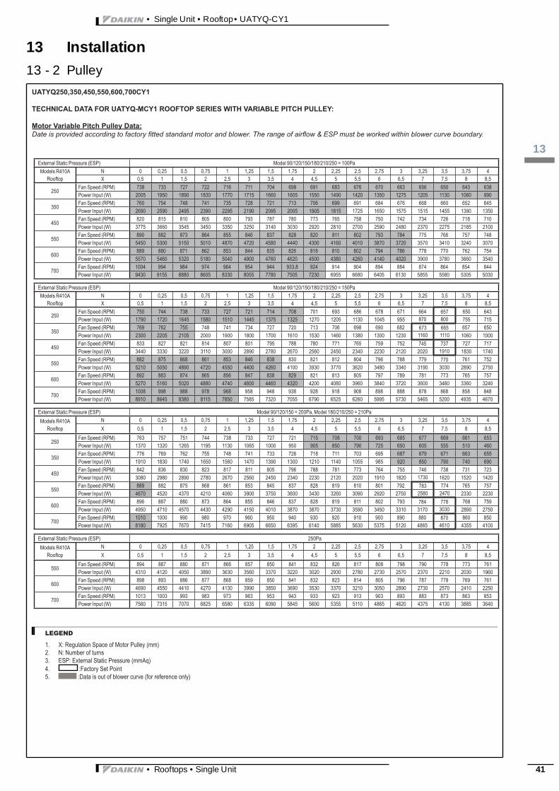
TECHNICAL DATA FOR UATYQ-MCY1 ROOFTOP SERIES WITH VARIABLE PITCH PULLEY:
Motor Variable Pitch Pulley Data:Date is provided according to factory fitted standard motor and blower. The range of airflow & ESP must be worked within blower curve boundary.
LEGEND
External Static Pressure (ESP) Model 90/120/150/180/210/250 = 100PaModels R410A
RooftopN 0 0,25 0,5 0,75 1 1,25 1,5 1,75 2 2,25 2,5 2,75 3 3,25 3,5 3,75 4X 0,5 1 1,5 2 2,5 3 3,5 4 4,5 5 5,5 6 6,5 7 7,5 8 8,5
250Fan Speed (RPM) 738 733 727 722 716 711 704 698 691 683 676 670 663 656 650 643 638Power Input (W) 2005 1950 1890 1830 1770 1715 1660 1605 1550 1490 1420 1350 1275 1205 1130 1060 990
350Fan Speed (RPM) 760 754 748 741 735 728 721 713 706 699 691 684 676 668 660 652 645Power Input (W) 2690 2590 2495 2390 2295 2190 2095 2005 1905 1815 1725 1650 1575 1515 1455 1390 1350
450Fan Speed (RPM) 820 815 810 805 800 793 787 780 773 765 758 750 742 734 726 718 710Power Input (W) 3775 3660 3545 3450 3350 3250 3140 3030 2920 2810 2700 2590 2480 2370 2275 2185 2100
550Fan Speed (RPM) 890 882 873 864 855 846 837 828 820 811 802 793 784 775 766 757 748Power Input (W) 5450 5300 5150 5010 4870 4720 4580 4440 4300 4160 4010 3870 3720 3570 3410 3240 3070
600Fan Speed (RPM) 889 880 871 862 853 844 835 826 818 810 802 794 786 778 770 762 754Power Input (W) 5570 5460 5320 5180 5040 4900 4760 4620 4500 4380 4260 4140 4020 3900 3780 3660 3540
700 Fan Speed (RPM) 1004 994 984 974 964 954 944 933,8 924 914 904 894 884 874 864 854 844Power Input (W) 9430 9155 8880 8605 8330 8055 7780 7505 7230 6955 6680 6405 6130 5855 5580 5305 5030
External Static Pressure (ESP) Model 90/120/150/180/210/250 = 150PaModels R410A
RooftopN 0 0,25 0,5 0,75 1 1,25 1,5 1,75 2 2,25 2,5 2,75 3 3,25 3,5 3,75 4X 0,5 1 1,5 2 2,5 3 3,5 4 4,5 5 5,5 6 6,5 7 7,5 8 8,5
250Fan Speed (RPM) 750 744 738 733 727 721 714 708 701 693 686 678 671 664 657 650 643Power Input (W) 1790 1720 1645 1580 1510 1445 1375 1325 1270 1205 1130 1045 955 870 800 755 715
350Fan Speed (RPM) 769 762 755 748 741 734 727 720 713 706 698 690 682 673 665 657 650Power Input (W) 2300 2205 2105 2000 1900 1800 1700 1610 1530 1460 1380 1300 1230 1160 1110 1060 1000
450Fan Speed (RPM) 833 827 821 814 807 801 795 788 780 771 765 759 752 745 737 727 717Power Input (W) 3440 3330 3220 3110 3000 2890 2780 2670 2560 2450 2340 2230 2120 2020 1910 1830 1740
550Fan Speed (RPM) 882 875 868 861 853 846 838 830 821 812 804 796 788 779 770 761 752Power Input (W) 5210 5050 4890 4720 4550 4400 4260 4100 3930 3770 3620 3480 3340 3190 3030 2890 2750
600Fan Speed (RPM) 892 883 874 865 856 847 838 829 821 813 805 797 789 781 773 765 757Power Input (W) 5270 5160 5020 4880 4740 4600 4460 4320 4200 4080 3960 3840 3720 3600 3480 3360 3240
700 Fan Speed (RPM) 1008 998 988 978 968 958 948 938 928 918 908 898 888 878 868 858 848Power Input (W) 8910 8645 8380 8115 7850 7585 7320 7055 6790 6525 6260 5995 5730 5465 5200 4935 4670
External Static Pressure (ESP) Model 90/120/150 = 200Pa, Model 180/210/250 = 210PaModels R410A
RooftopN 0 0,25 0,5 0,75 1 1,25 1,5 1,75 2 2,25 2,5 2,75 3 3,25 3,5 3,75 4X 0,5 1 1,5 2 2,5 3 3,5 4 4,5 5 5,5 6 6,5 7 7,5 8 8,5
250Fan Speed (RPM) 763 757 751 744 738 733 727 721 715 708 700 693 685 677 669 661 653Power Input (W) 1370 1320 1265 1195 1130 1065 1000 950 905 850 790 725 650 605 555 510 460
350Fan Speed (RPM) 776 769 762 755 748 741 733 726 718 711 703 695 687 679 671 663 655Power Input (W) 1910 1830 1740 1650 1560 1470 1390 1300 1210 1140 1055 985 920 850 790 740 690
450Fan Speed (RPM) 842 836 830 823 817 811 805 796 788 781 773 764 755 746 738 731 723Power Input (W) 3080 2980 2890 2780 2670 2560 2450 2340 2230 2120 2020 1910 1820 1730 1620 1520 1420
550Fan Speed (RPM) 889 882 875 868 861 853 845 837 828 819 810 801 792 783 774 765 757Power Input (W) 4670 4520 4370 4210 4060 3900 3750 3600 3430 3260 3090 2920 2750 2580 2470 2330 2230
600Fan Speed (RPM) 896 887 880 873 864 855 846 837 828 819 811 802 793 784 778 768 759Power Input (W) 4950 4710 4570 4430 4290 4150 4010 3870 3870 3730 3590 3450 3310 3170 3030 2890 2750
700 Fan Speed (RPM) 1010 1000 990 980 970 960 950 940 930 920 910 900 890 880 870 860 850Power Input (W) 8180 7925 7670 7415 7160 6905 6650 6395 6140 5885 5630 5375 5120 4865 4610 4355 4100
External Static Pressure (ESP) 250PaModels R410A
RooftopN 0 0,25 0,5 0,75 1 1,25 1,5 1,75 2 2,25 2,5 2,75 3 3,25 3,5 3,75 4X 0,5 1 1,5 2 2,5 3 3,5 4 4,5 5 5,5 6 6,5 7 7,5 8 8,5
550Fan Speed (RPM) 894 887 880 871 866 857 850 841 832 826 817 808 798 790 778 773 761Power Input (W) 4310 4120 4050 3890 3630 3560 3370 3220 3020 2930 2780 2730 2570 2370 2210 2030 1960
600Fan Speed (RPM) 898 893 886 877 868 859 850 841 832 823 814 805 796 787 778 769 761Power Input (W) 4690 4550 4410 4270 4130 3990 3850 3690 3530 3370 3210 3050 2890 2730 2570 2410 2250
700 Fan Speed (RPM) 1013 1003 993 983 973 963 953 943 933 923 913 903 893 883 873 863 853Power Input (W) 7560 7315 7070 6825 6580 6335 6090 5845 5600 5355 5110 4865 4620 4375 4130 3885 3640
1. X: Regulation Space of Motor Pulley (mm)2. N: Number of turns3. ESP: External Static Pressure (mmAq)4. :Factory Set Point5. :Data is out of blower curve (for reference only)
• Rooftops • Single Unit 41
• Single Unit • Rooftop • UATYQ-CY1
114
42
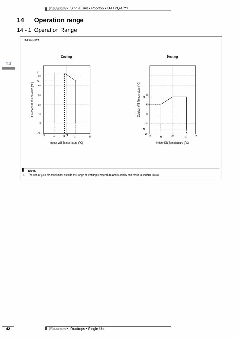
14 Operation range
14 - 1 Operation Range• Rooftops • Single Unit
3
115
• Single Unit • Rooftop • UATYQ-CY1
15 Specification text
15 - 1 Specification Text• Rooftops • Single Unit 43

• Single Unit • Rooftop • UATYQ-CY1
115
44
15 Specification text
15 - 1 Specification Text• Rooftops • Single Unit

3
115
• Single Unit • Rooftop • UATYQ-CY1
15 Specification text
15 - 1 Specification Text• Rooftops • Single Unit 45


Daikin’s unique posit ion as a m anufacturer of aircondit ioning equipment, com pressors and refriger-ants has led to it s close involvement in environmen-tal issues. For several years Daik in has had theintenti on to become a leader i n the provis ion ofproducts that have limited i mpact on the environ-ment. This chall enge demands the eco desi gn anddevelopment of a wide range of products and an en-ergy m anagement system, resulting in energy con-servat ion and a reduct ion of waste.
These products are not within the scope ofthe Eurovent certif ication program
EE
DE
N13
-120
• 1
1/12
• C
opyr
igh
t Da
ikin
T
he p
rese
nt p
ubl
icat
ion
su
pers
ede
s E
ED
EN
12-1
20The present leaflet is drawn up by way of informati on only and does notconst itute an of fer binding upon Daikin Europe N.V .. Daik in Europe N.V .has compiled the content of this l eaf let to the best of it s knowl edge. Noexpress or i mplied warranty is given for the completeness, accuracy, re-liability or fitness for parti cular purpose of its content and the productsand services presented therein. Specifications are subject to changewithout prior not ice. Dai kin Europe N.V. expl icit ly rejects any liabi lity forany direct or indirect damage, in the broadest sense, arising from or re-lated to the use and/or interpretation of thi s leaf let. Al l content i s copy-righted by Daikin Europe N.V.
BARCODE Daikin products are dist ributed by:
Naamloze Ve nnootschap - Zandvoordestraa t 30 0, B-8400 Oostend e - Be lgium - www.d aikin.eu - BE 0412 120 336 - RPR Ooste nde