Air Conditioners Technical Data - daikintech.co.ukMB)/2012/FXMQ-MAVE/... · FXMQ-MA EEDEN11-204 Air...
20
FXMQ-MA EEDEN11-204 Air Conditioners Large concealed ceiling unit Technical Data
-
Upload
hoangthuan -
Category
Documents
-
view
214 -
download
0
Transcript of Air Conditioners Technical Data - daikintech.co.ukMB)/2012/FXMQ-MAVE/... · FXMQ-MA EEDEN11-204 Air...

FXMQ-MA
E E D E N 1 1 - 2 0 4
Air Conditioners
Large concealed ce i l ing uni t
Technical Data

FXMQ-MA
E E D E N 1 1 - 2 0 4
Air Conditioners
Large concealed ce i l ing uni t
Technical Data
• VRV ® Systems • Indoor Unit 1
• Indoor Unit • Large concealed ceiling unit • FXMQ-MA
TABLE OF CONTENTSFXMQ-MA
1 Specifications . . . . . . . . . . . . . . . . . . . . . . . . . . . . . . . . . . . . . . . . . . . . . . . . . . . . . . . 2
Technical Specifications . . . . . . . . . . . . . . . . . . . . . . . . . . . . . . . . . . . . . . . . . . . . . 2
Electrical Specifications . . . . . . . . . . . . . . . . . . . . . . . . . . . . . . . . . . . . . . . . . . . . . . 3
2 Safety device settings . . . . . . . . . . . . . . . . . . . . . . . . . . . . . . . . . . . . . . . . . . . . . 4
Safety Device Settings . . . . . . . . . . . . . . . . . . . . . . . . . . . . . . . . . . . . . . . . . . . . . . . 4
3 Options . . . . . . . . . . . . . . . . . . . . . . . . . . . . . . . . . . . . . . . . . . . . . . . . . . . . . . . . . . . . . . 5
Options . . . . . . . . . . . . . . . . . . . . . . . . . . . . . . . . . . . . . . . . . . . . . . . . . . . . . . . . . . . . . . . 5
4 Control systems . . . . . . . . . . . . . . . . . . . . . . . . . . . . . . . . . . . . . . . . . . . . . . . . . . . . 6
Control Systems . . . . . . . . . . . . . . . . . . . . . . . . . . . . . . . . . . . . . . . . . . . . . . . . . . . . . 6
5 Capacity tables . . . . . . . . . . . . . . . . . . . . . . . . . . . . . . . . . . . . . . . . . . . . . . . . . . . . . 7
Cooling Capacity Tables . . . . . . . . . . . . . . . . . . . . . . . . . . . . . . . . . . . . . . . . . . . . . 7
Heating Capacity Tables . . . . . . . . . . . . . . . . . . . . . . . . . . . . . . . . . . . . . . . . . . . . . 8
6 Dimensional drawings . . . . . . . . . . . . . . . . . . . . . . . . . . . . . . . . . . . . . . . . . . . . . 9
Dimensional Drawings . . . . . . . . . . . . . . . . . . . . . . . . . . . . . . . . . . . . . . . . . . . . . . . 9
7 Centre of gravity . . . . . . . . . . . . . . . . . . . . . . . . . . . . . . . . . . . . . . . . . . . . . . . . . . . 10
Centre of Gravity . . . . . . . . . . . . . . . . . . . . . . . . . . . . . . . . . . . . . . . . . . . . . . . . . . . . 10
8 Piping diagrams . . . . . . . . . . . . . . . . . . . . . . . . . . . . . . . . . . . . . . . . . . . . . . . . . . . 11
Piping Diagrams . . . . . . . . . . . . . . . . . . . . . . . . . . . . . . . . . . . . . . . . . . . . . . . . . . . . 11
9 Wiring diagrams . . . . . . . . . . . . . . . . . . . . . . . . . . . . . . . . . . . . . . . . . . . . . . . . . . . 12
Wiring Diagrams - Single Phase . . . . . . . . . . . . . . . . . . . . . . . . . . . . . . . . . . . 12
10 Sound data . . . . . . . . . . . . . . . . . . . . . . . . . . . . . . . . . . . . . . . . . . . . . . . . . . . . . . . . . 13
Sound Level Data . . . . . . . . . . . . . . . . . . . . . . . . . . . . . . . . . . . . . . . . . . . . . . . . . . . 13
Sound Pressure Spectrum . . . . . . . . . . . . . . . . . . . . . . . . . . . . . . . . . . . . . . . . . . 14
11 Fan characteristics . . . . . . . . . . . . . . . . . . . . . . . . . . . . . . . . . . . . . . . . . . . . . . . . 15
Fan Characteristics . . . . . . . . . . . . . . . . . . . . . . . . . . . . . . . . . . . . . . . . . . . . . . . . . 15
12 Installation . . . . . . . . . . . . . . . . . . . . . . . . . . . . . . . . . . . . . . . . . . . . . . . . . . . . . . . . . . 16
Suspension Bolt Pitch Position . . . . . . . . . . . . . . . . . . . . . . . . . . . . . . . . . . . . . . 16
Service Space . . . . . . . . . . . . . . . . . . . . . . . . . . . . . . . . . . . . . . . . . . . . . . . . . . . . . . . 17
• Indoor Unit • Large concealed ceiling unit • FXMQ-MA
• VRV ® Systems • Indoor Unit2
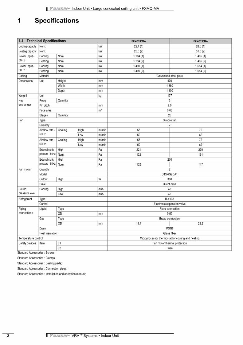
1 Specifications
Indoor Unit VRV ® Systems FXMQ-MA Large conce
Standard Accessories : Screws;
Standard Accessories : Clamps;
Standard Accessories : Sealing pads;
Standard Accessories : Connection pipes;
Standard Accessories : Installation and operation manual;
1-1 Technical Specifications FXMQ200MA FXMQ250MA
Cooling capacity Nom. kW 22.4 (1) 28.0 (1)
Heating capacity Nom. kW 25.0 (2) 31.5 (2)
Power input - 50Hz
Cooling Nom. kW 1.294 (1) 1.465 (1)
Heating Nom. kW 1.294 (2) 1.465 (2)
Power input - 60Hz
Cooling Nom. kW 1.490 (1) 1.684 (1)
Heating Nom. kW 1.490 (2) 1.684 (2)
Casing Material Galvanised steel plate
Dimensions Unit Height mm 470
Width mm 1,380
Depth mm 1,100
Weight Unit kg 137
Heat exchanger
Rows Quantity 3
Fin pitch mm 2.0
Face area m² 0.68
Stages Quantity 26
Fan Type Sirocco fan
Quantity 2
Air flow rate - 50Hz
Cooling High m³/min 58 72
Low m³/min 50 62
Air flow rate - 60Hz
Cooling High m³/min 58 72
Low m³/min 50 62
External static pressure - 50Hz
High Pa 221 270
Nom. Pa 132 191
External static pressure - 60Hz
High Pa 270
Nom. Pa 132 147
Fan motor Quantity 2
Model D13/4G2DA1
Output High W 380
Drive Direct drive
Sound pressure level
Cooling High dBA 48
Low dBA 45
Refrigerant Type R-410A
Control Electronic expansion valve
Piping connections
Liquid Type Flare connection
OD mm 9.52
Gas Type Braze connection
OD mm 19.1 22.2
Drain PS1B
Heat insulation Glass fiber
Temperature control Microprocessor thermostat for cooling and heating
Safety devices Item 01 Fan motor thermal protection
02 Fuse

• VRV ® Systems • Indoor Unit 3
• Indoor Unit • Large concealed ceiling unit • FXMQ-MA
1 Specifications
Notes
(1) Cooling: indoor temp. 27ºCDB, 19ºCWB; outdoor temp. 35ºCDB; equivalent piping length: 7.5m (horizontal)
(2) Heating: indoor temp. 20ºCDB; outdoor temp. 7ºCDB, 6ºCWB; equivalent refrigerant piping: 7.5m (horizontal)
(3) Capacities are net, including a deduction for cooling (an addition for heating) for indoor fan motor heat.
(4) The external static pressure is changeable: change the connectors inside the electrical box, this pressure means: High static pressure - Standard
(5) The air filter is not a standard accessory, but please mount it in the duct system of the suction side. Select its colorimetric method (gravity method) 50% or more.
(6) Sound pressure levels are measured at 220V.
(7) Voltage range: units are suitable for use on electrical systems where voltage supplied to unit terminal is not below or above listed range limits.
(8) Maximum allowable voltage range variation between phases is 2%.
(9) MCA/MFA: MCA = 1.25 x FLA
(10) MFA ≤ 4 x FLA
(11) Next lower standard fuse rating minimum 15A
(12) Select wire size based on the value of MCA
(13) Instead of a fuse, use a circuit breaker
1-2 Electrical Specifications FXMQ200MA FXMQ250MA
Power supply Name VE
Phase 1~
Frequency Hz 50/60
Voltage V 220-240/220
Voltage range Min. % -10
Max. % 10
Current - 50Hz Minimum circuit amps (MCA) A 8.1 9.0
Maximum fuse amps (MFA) A 15
Full load amps (FLA)
Total A 6.5 7.2
Current - 60Hz Minimum circuit amps (MCA) A 9.0 10.1
Maximum fuse amps (MFA) A 15
Full load amps (FLA)
Total A 7.2 8.1
• Indoor Unit • Large concealed ceiling unit • FXMQ-MA
• VRV ® Systems • Indoor Unit4
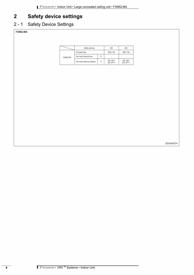
2 Safety device settings
2 - 1 Safety Device Settings

• VRV ® Systems • Indoor Unit 5
• Indoor Unit • Large concealed ceiling unit • FXMQ-MA
3 Options
3 - 1 Options
FXMQ200MA FXMQ250MAEV052L03UDKTIKPMUPNIARD
082L273JFAK%56RETLIFYCNEICIFFEHGIH
082L373JFAK%09RETLIFYCNEICIFFEHGIH
082L5073JDKREBMAHCRETLIF
082L173JFAKRETLIFEFILGNOLTNEMECALPER
3D040334B
Main Unit
High Efficiency Filter
High Efficiency Filter
Filter Chamber
Drain Pump Kit

• Indoor Unit • Large concealed ceiling unit • FXMQ-MA
• VRV ® Systems • Indoor Unit6
4 Control systems
4 - 1 Control Systems

• VRV ® Systems • Indoor Unit 7
• Indoor Unit • Large concealed ceiling unit • FXMQ-MA
5 Capacity tables
5 - 1 Cooling Capacity Tables
FXMQ-MA
TC: Total capacity;kW – SHC: Sensible capacity;kW
Unit sizeNominal capacity
Outdoorair temp.
Indoor air temperature14.0WB 16.0WB 18.0WB 19.0WB 20.0WB 22.0WB 24.0WB20.0DB 23.0DB 26.0DB 27.0DB 28.0DB 30.0DB 32.0DB
°CDB TC SHC TC SHC TC SHC TC SHC TC SHC TC SHC TC SHC200 22.4 10.0 15.1 13.4 18.0 14.9 21.0 16.3 22.4 16.8 23.8 17.0 26.8 17.6 29.4 17.8
12.0 15.1 13.4 18.0 14.9 21.0 16.3 22.4 16.8 23.8 17.0 26.8 17.6 29.0 17.614.0 15.1 13.4 18.0 14.9 21.0 16.3 22.4 16.8 23.8 17.0 26.8 17.6 28.7 17.416.0 15.1 13.4 18.0 14.9 21.0 16.3 22.4 16.8 23.8 17.0 26.8 17.6 28.3 17.218.0 15.1 13.4 18.0 14.9 21.0 16.3 22.4 16.8 23.8 17.0 26.8 17.6 27.9 16.920.0 15.1 13.4 18.0 14.9 21.0 16.3 22.4 16.8 23.8 17.0 26.8 17.6 27.5 16.721.0 15.1 13.4 18.0 14.9 21.0 16.3 22.4 16.8 23.8 17.0 26.8 17.6 27.4 16.623.0 15.1 13.4 18.0 14.9 21.0 16.3 22.4 16.8 23.8 17.0 26.4 17.3 27.0 16.425.0 15.1 13.4 18.0 14.9 21.0 16.3 22.4 16.8 23.8 17.0 26.1 17.1 26.6 16.227.0 15.1 13.4 18.0 14.9 21.0 16.3 22.4 16.8 23.8 17.0 25.7 16.8 26.2 16.129.0 15.1 13.4 18.0 14.9 21.0 16.3 22.4 16.8 23.8 17.0 25.3 16.6 25.8 15.931.0 15.1 13.4 18.0 14.9 21.0 16.3 22.4 16.8 23.8 17.0 24.9 16.4 25.4 15.733.0 15.1 13.4 18.0 14.9 21.0 16.3 22.4 16.8 23.8 17.0 24.5 16.3 25.0 15.635.0 15.1 13.4 18.0 14.9 21.0 16.3 22.4 16.8 23.6 17.0 24.2 16.1 24.6 15.437.0 15.1 13.4 18.0 14.9 21.0 16.3 22.4 16.8 23.2 16.8 23.8 16.0 24.3 15.339.0 15.1 13.4 18.0 14.9 21.0 16.3 22.4 16.8 22.8 16.6 23.4 15.8 23.9 15.1
250 28.0 10.0 18.9 16.9 22.5 18.5 26.2 20.4 28.0 20.9 29.8 21.2 33.5 22.1 36.8 22.112.0 18.9 16.9 22.5 18.5 26.2 20.4 28.0 20.9 29.8 21.2 33.5 22.1 36.3 21.814.0 18.9 16.9 22.5 18.5 26.2 20.4 28.0 20.9 29.8 21.2 33.5 22.1 35.9 21.616.0 18.9 16.9 22.5 18.5 26.2 20.4 28.0 20.9 29.8 21.2 33.5 22.1 35.4 21.318.0 18.9 16.9 22.5 18.5 26.2 20.4 28.0 20.9 29.8 21.2 33.5 22.1 34.9 21.020.0 18.9 16.9 22.5 18.5 26.2 20.4 28.0 20.9 29.8 21.2 33.5 22.1 34.4 20.721.0 18.9 16.9 22.5 18.5 26.2 20.4 28.0 20.9 29.8 21.2 33.5 22.1 34.2 20.623.0 18.9 16.9 22.5 18.5 26.2 20.4 28.0 20.9 29.8 21.2 33.0 21.7 33.7 20.325.0 18.9 16.9 22.5 18.5 26.2 20.4 28.0 20.9 29.8 21.2 32.6 21.5 33.2 20.227.0 18.9 16.9 22.5 18.5 26.2 20.4 28.0 20.9 29.8 21.2 32.1 21.2 32.8 20.029.0 18.9 16.9 22.5 18.5 26.2 20.4 28.0 20.9 29.8 21.2 31.6 20.9 32.3 19.931.0 18.9 16.9 22.5 18.5 26.2 20.4 28.0 20.9 29.8 21.2 31.1 20.6 31.8 19.733.0 18.9 16.9 22.5 18.5 26.2 20.4 28.0 20.9 29.8 21.2 30.6 20.4 31.3 19.535.0 18.9 16.9 22.5 18.5 26.2 20.4 28.0 20.9 29.5 21.1 30.2 20.2 30.8 19.437.0 18.9 16.9 22.5 18.5 26.2 20.4 28.0 20.9 29.0 20.9 29.7 20.0 30.4 19.239.0 18.9 16.9 22.5 18.5 26.2 20.4 28.0 21.0 28.5 20.6 29.2 19.8 29.9 19.0

• Indoor Unit • Large concealed ceiling unit • FXMQ-MA
• VRV ® Systems • Indoor Unit8
5 Capacity tables
5 - 2 Heating Capacity Tables
FXMQ-MA
Unit Size Nominal capacityOutdoor
air temperatureIndoor air temperature °CDB
16.0 18.0 20.0 21.0 22.0 24.0°CDB °CWB kW kW kW kW kW kW
200 25.0 -19.8 -20.0 14.8 14.7 14.7 14.7 14.6 14.6 -18.8 -19.0 15.2 15.2 15.1 15.1 15.1 15.0-16.7 -17.0 16.1 16.0 16.0 16.0 16.0 15.9-14.7 -15.0 17.0 16.9 16.9 16.9 16.8 16.8-12.6 -13.0 17.9 17.8 17.8 17.7 17.7 17.7-10.5 -11.0 18.7 18.7 18.6 18.6 18.6 18.6-9.5 -10.0 19.2 19.1 19.1 19.1 19.0 19.0-8.5 -9.1 19.6 19.5 19.5 19.5 19.4 19.4-7.0 -7.6 20.2 20.2 20.2 20.1 20.1 20.1-5.0 -5.6 21.1 21.1 21.0 21.0 21.0 20.9-3.0 -3.7 22.0 21.9 21.9 21.9 21.8 21.80.0 -0.7 23.3 23.2 23.2 23.2 23.2 21.83.0 2.2 24.6 24.5 24.5 24.2 23.4 21.85.0 4.1 25.4 25.4 25.0 24.2 23.4 21.87.0 6.0 26.2 26.2 25.0 24.2 23.4 21.89.0 7.9 27.1 26.6 25.0 24.2 23.4 21.811.0 9.8 27.9 26.6 25.0 24.2 23.4 21.813.0 11.8 28.2 26.6 25.0 24.2 23.4 21.8 15.0 13.7 28.2 26.6 25.0 24.2 23.4 21.8
250 31.5 -19.8 -20.0 18.6 18.5 18.5 18.5 18.4 18.4 -18.8 -19.0 19.2 19.1 19.0 19.0 19.0 18.9-16.7 -17.0 20.3 20.2 20.2 20.1 20.1 20.0-14.7 -15.0 21.4 21.3 21.3 21.2 21.2 21.2-12.6 -13.0 22.5 22.4 22.4 22.4 22.3 22.3-10.5 -11.0 23.6 23.6 23.5 23.5 23.4 23.4-9.5 -10.0 24.2 24.1 24.1 24.0 24.0 23.9-8.5 -9.1 24.7 24.6 24.6 24.5 24.5 24.4-7.0 -7.6 25.5 25.4 25.4 25.4 25.3 25.3-5.0 -5.6 26.6 26.6 26.5 26.5 26.4 26.4-3.0 -3.7 27.7 27.6 27.6 27.5 27.5 27.50.0 -0.7 29.3 29.3 29.2 29.2 29.2 27.53.0 2.2 31.0 30.9 30.8 30.5 29.5 27.55.0 4.1 32.0 32.0 31.5 30.5 29.5 27.57.0 6.0 33.1 33.0 31.5 30.5 29.5 27.59.0 7.9 34.1 33.5 31.5 30.5 29.5 27.511.0 9.8 35.2 33.5 31.5 30.5 29.5 27.513.0 11.8 35.5 33.5 31.5 30.5 29.5 27.515.0 13.7 35.5 33.5 31.5 30.5 29.5 27.5

• VRV ® Systems • Indoor Unit 9
• Indoor Unit • Large concealed ceiling unit • FXMQ-MA
6 Dimensional drawings
6 - 1 Dimensional Drawings
FXMQ200,250MA
3D038851
32 - ø 4.7 hole(All around)
1,100 or more(Service space)
650 o
r more
(Servic
e spa
ce)
Discharge side
View
Suction side (Note. 2)
Inspection hole 600 or more
Appro
x32 - ø 4.7 hole(All around)
(All around)
View
(All around)16 - ø 8 hole
Piping size (field supply)
Model Gas LiquidFXMQ200MA ø 19.1 attached piping ø 9.5FXMQ250MA ø 22.2 attached piping ø 9.5
NOTES
1 Location of unit’s name plate: switch box surface.
2 Mount the air filter at the suction side. (Select its colorimethod (gravity method) 50% or more).
Nr Part name Description1 Liquid pipe connection Flare connection2 Gas pipe connection Attendant piping connection3 Ground terminal M5 (Inside switch box)4 Switch box5 Power supply wiring connection6 Transmission wiring connection7 Hook M108 Discharge companion flange9 Suction flange10 Attached piping Brazing11 Name plate12 Drain piping connection PS1B Internal thread
VP25 (O.D. ø33.349, I.D. ø30.391)13 Water supply port

• Indoor Unit • Large concealed ceiling unit • FXMQ-MA
• VRV ® Systems • Indoor Unit10
7 Centre of gravity
7 - 1 Centre of Gravity
FXMQ200,250MA
4D035171
Air outlet Air inlet
• VRV ® Systems • Indoor Unit 11
• Indoor Unit • Large concealed ceiling unit • FXMQ-MA
8 Piping diagrams
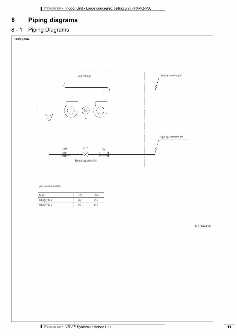
8 - 1 Piping Diagrams
FXMQ-MA
4D034245
Heat exchanger
Fan
Filter Filter
Electronic expansion valve
Liquid pipe connection port
Gas pipe connection port
Piping connection diameters
Model Gas Liquid
FXMQ200MA ø19.1 ø9.5
FXMQ250MA ø22.2 ø9.5
D
• Indoor Unit • Large concealed ceiling unit • FXMQ-MA
• VRV ® Systems • Indoor Unit12
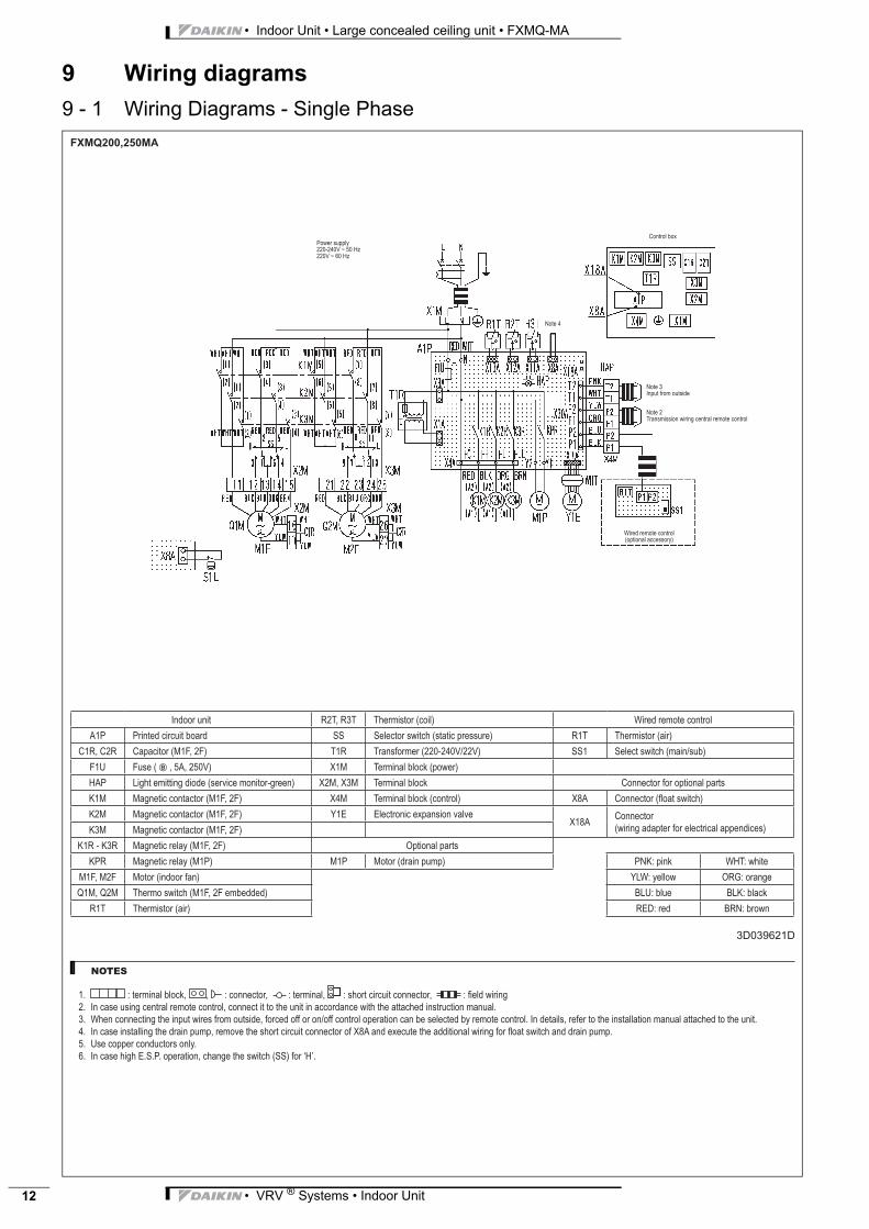
9 Wiring diagrams
9 - 1 Wiring Diagrams - Single Phase
�
• VRV ® Systems • Indoor Unit 13
• Indoor Unit • Large concealed ceiling unit • FXMQ-MA
10 Sound data
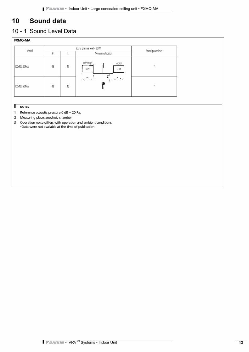
10 - 1 Sound Level Data
FXMQ-MA
NOTES
1 Reference acoustic pressure 0 dB = 20 Pa.
2 Measuring place: anechoic chamber
3 Operation noise differs with operation and ambient conditions.*Data were not available at the time of publication
ModelSound pressure level - 220V
Sound power levelH L Measuring location
FXMQ200MA 48 45 *
FXMQ250MA 48 45 *
Discharge Suction
Duct Duct

• Indoor Unit • Large concealed ceiling unit • FXMQ-MA
• VRV ® Systems • Indoor Unit14
10 Sound data
10 - 2 Sound Pressure Spectrum
FXMQ200MA 4D035168
Approximatethreshold hearingfor continuousnoise
Octave band center frequency (Hz)
Octav
e ban
d sou
nd pr
essure
level
dB (O
dB =
0.00
02 μ
bar)
FXMQ250MA 4D035169
Approximatethreshold hearingfor continuousnoise
Octave band center frequency (Hz)
Octav
e ban
d sou
nd pr
essure
level
dB (O
dB =
0.00
02 μ
bar)
• VRV ® Systems • Indoor Unit 15
• Indoor Unit • Large concealed ceiling unit • FXMQ-MA
11 Fan characteristics
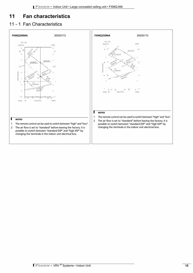
11 - 1 Fan Characteristics
NOTES
1 The remote control can be used to switch between “high” and “low”.
2 The air flow is set to “standard” before leaving the factory. It is possible to switch between “standard ESP” and “high ESP” by changing the terminals in the indoor unit electrical box.
FXMQ200MA 3D035172
50 HZ 220V
(mmH20) (Pa)
Low (high ESP)High (high ESP)
Upper l
imit of
ESP
(high E
SP)
(mmH20)
Upper limit of
ESP
(standard E
SP)
Lower limit of E
SP
(high ESP)
High(standard ESP)
Low(standard ESP)
Lower limit of ESP
(standard ESP)
(mmH20) (Pa) (mmH20)Air flow (m3/min)
Extern
al sta
tic pre
ssure
NOTES
1 The remote control can be used to switch between “high” and “low”.
2 The air flow is set to “standard” before leaving the factory. It is possible to switch between “standard ESP” and “high ESP” by changing the terminals in the indoor unit electrical box.
FXMQ250MA 3D035173
50 HZ 220V
(mmH20) (Pa) (mmH20)
High (high ESP)
Low (high ESP)Upper li
mit of ESP
(high ES
P)
Upper limit of
ESP
(standard E
SP)Lower lim
it of ESP
(high ESP)
High(standard ESP)
Low(standard ESP)
Lower limit of ESP
(standard ESP)
(mmH20) (Pa) Air flow (m3/min) (mmH20)
Extern
al sta
tic pre
ssure

• Indoor Unit • Large concealed ceiling unit • FXMQ-MA
• VRV ® Systems • Indoor Unit16
12 Installation
12 - 1 Suspension Bolt Pitch Position
AM052,002QMXF
3P086156-2-5
Suspension bolt (x4)
Indoor unit
1,148
1,100
1,296
1,380
Inspection hatch 600Ap
prox.
150 m
m
Air outlet
1,100 or more
(service space)
Air inlet
Ceiling slab
Anchor
Long nut or turn-buckle
Suspension bolt
Indoor unit
NOTES
1 Install a canvas duct to the air discharge outlet and air inlet so that vibration from the machine body is not transmitted to the duct or ceiling. You should also apply acoustic (insulation material) to the inside of the duct, and vibration insulation rubber to the suspension bolts.
2 Install suspension bolts .Use bolts of 10 mm diameter.Install the equipment where supporting structures are strong enough to bear the equipment’s weight. Use embedded inserts or anchor bolts with new buildings and hole-in-anchors with old buildings.
NOTE
1 All the above parts are to be procured in the field.
• VRV ® Systems • Indoor Unit 17
• Indoor Unit • Large concealed ceiling unit • FXMQ-MA
12 Installation
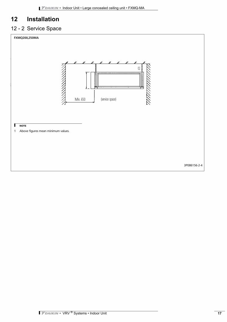
12 - 2 Service Space
AM052,002QMXF
3P086156-2-4
(service space)Min. 650
470
NOTE
1 Above figures mean minimum values.

Naamloze Vennootschap - Zandvoordestraat 300, B-8400 Oostende - Belgium - www.daikin.eu - BE 0412 120 336 - RPR OostendeNaamloze Vennootschap - Zandvoordestraat 300, B-8400 Oostende - Belgium - www.daikin.eu - BE 0412 120 336 - RPR Oostende EED
EN11
-204
• C
D •
06/1
1 • C
opyr
ight
Dai
kin
The
pres
ent p
ublic
atio
n su
pers
edes
EED
EN10
-204
Prin
ted
in B
elgi
um b
y La
nnoo
(ww
w.la
nnoo
prin
t.be)
, a c
ompa
ny w
hose
con
cern
fo
r the
env
ironm
ent i
s se
t in
the
EMAS
and
ISO
140
01 s
yste
ms.
Resp
onsi
ble
Ed
itor
: Dai
kin
Euro
pe
N.V
., Z
and
voor
des
traa
t 30
0, B
-840
0 O
oste
nde
Daikin’s unique position as a manufacturer of air conditioning equipment, compressors and refrigerants has led to its close involvement in environmental issues. For several years Daikin has had the intention to become a leader in the provision of products that have limited impact on the environment. This challenge demands the eco design and development of a wide range of products and an energy management system, resulting in energy conservation and a reduction of waste.
Daikin products are distributed by:
VRV® products are not within the scope of the Eurovent certification programme.
The present publication is drawn up by way of information only and does not constitute an offer binding upon Daikin Europe N.V.. Daikin Europe N.V. has compiled the content of this publication to the best of its knowledge. No express or implied warranty is given for the completeness, accuracy, reliability or fitness for particular purpose of its content and the products and services presented therein. Specifications are subject to change without prior notice. Daikin Europe N.V. explicitly rejects any liability for any direct or indirect damage, in the broadest sense, arising from or related to the use and/or interpretation of this publication. All content is copyrighted by Daikin Europe N.V..