AIR ACCIDENT INVESTIGATION SECTOR - General Civil … · · 2013-10-03Includes pushback/power...
28
AAIS Case Reference: 11-2012 AIR ACCIDENT INVESTIGATION SECTOR FINAL SERIOUS INCIDENT INVESTIGATION REPORT Pushback Collision Airbus A330-243 [A6-EYN] Boeing 777-300 [A6-ETD] Abu Dhabi International Airport [AUH] Terminal 1, Stands 121 and 122 May 06 2012 General Civil Aviation Authority of the United Arab Emirates
Transcript of AIR ACCIDENT INVESTIGATION SECTOR - General Civil … · · 2013-10-03Includes pushback/power...

General Civil Aviation Authority
AAIS Case Reference: 11-2012
AIR ACCIDENT INVESTIGATION SECTOR FINAL
SERIOUS INCIDENT INVESTIGATION REPORT
Pushback Collision
Airbus A330-243 [A6-EYN]
Boeing 777-300 [A6-ETD] Abu Dhabi International Airport [AUH]
Terminal 1, Stands 121 and 122 May 06 2012
General Civil Aviation Authority of the United Arab Emirates

GCAA/AAIS/11-2012/AUH 2
AIR ACCIDENT INVESTIGATION SECTOR STATEMENT
THIS INVESTIGATION HAS BEEN CARRIED OUT IN ACCORDANCE WITH THE GENERAL CIVIL AVIATION AUTHORITY CAR PART VI AND ANNEX 13 TO THE ICAO CONVENTION ON INTERNATIONAL CIVIL AVIATION.
THE SOLE OBJECTIVE OF THE INVESTIGATION OF AN ACCIDENT OR INCIDENT SHALL BE THE PREVENTION OF ACCIDENTS AND INCIDENTS. IT SHALL NOT BE THE PURPOSE OF SUCH AN INVESTIGATION TO APPORTION BLAME OR LIABILITY.

GCAA/AAIS/11-2012/AUH 3
Contents
Synopsis .................................................................................................................................. 4
Abbreviations/Phrases Used in this Report .......................................................................... 4
ADREP Serious Incident Classification .................................................................................... 5
1. Factual Information ............................................................................................................ 6
1.1 History of the flight ....................................................................................................... 6
1.2 Injuries to Person .......................................................................................................... 6
1.3 Damage to aircraft. ....................................................................................................... 7
1.4 Other Damage .............................................................................................................. 8
1.5 Personnel information .................................................................................................. 8
1.6 Aircraft Information ...................................................................................................... 9
1.7 Meteorological Information ....................................................................................... 11
1.8 Aids to Navigation ....................................................................................................... 11
1.9 Communications ......................................................................................................... 11
1.10 Aerodrome Information .......................................................................................... 12
1.11 Flight Recorders ...................................................................................................... 17
1.17 Organisational and Management Information ....................................................... 17
1.18 Additional Information ........................................................................................... 17
2 Analysis .......................................................................................................................... 18
3. Findings, Causes and Contributing Factors ............................................................... 24
4. Safety Recommendations .......................................................................................... 26
• GCAA Safety Recommendation #08/2013 ............................................................... 26
• GCAA Safety Recommendation #09/2013 ............................................................... 26
• GCAA Safety Recommendation #10/2013 ............................................................... 26
• GCAA Safety Recommendation #11/2013 ............................................................... 26
• GCAA Safety Recommendation #12/2013 ............................................................... 26
• GCAA Safety Recommendation #13/2013 ............................................................... 27
• GCAA Safety Recommendation #14/2013 ............................................................... 27
• GCAA Safety Recommendation #15/2013 ............................................................... 27
• GCAA Safety Recommendation #16/2013 ............................................................... 27
• GCAA Safety Recommendation #17/2013 ............................................................... 27
GCAA/AAIS/11-2012/AUH 4
Synopsis
On the May 5th 2012 at 22:22 UTC, during push back from parking position 122 at Abu Dhabi International Airport [AUH], the right winglet of an A330, A6-EYN, contacted the left wing tip of a B777, A6-ETD, which was parked in the adjacent parking position 121. The A330 was operating as EY057, pushing back for a scheduled service to Brussels with 249 passengers and 11 crew onboard. The flight departed, following CDL maintenance intervention1 (removal of the winglet). The B-777 was operating as EY418 scheduled service to Kuala Lumpur and was delayed AOG pending repair to the LH wingtip.
Abbreviations/Phrases Used in this Report
ABBREVIATIONS/PHRASES USED IN THIS REPORT ADAC Abu Dhabi Airports Company AIP Aeronautical Information Publication ACAPM Aircraft Characteristics for Airport Planning Manual AOG Aircraft On Ground AUH Abu Dhabi International Airport CAPT Captain CAR Civil Aviation Regulations CDL Configuration Deviation List CET Civil Evening Twilight CVR Cockpit Voice Recorder D1 Limitation for breakaway power jet blast D2 Distance from NLG to Nacelle Engine Exhaust DFDR Digital Flight Data Recorder EASG Etihad Airport Services Ground EET Engine Exhaust Temperatures EEV Engine Exhaust Velocity F/O First Officer F Scale Fujita–Pearson scale fps Feet Per Second GCAA General Civil Aviation Authority GST Gulf Standard Time [UTC+4 hours] ICAO International Civil Aviation Organization kph Kilometer Per Hour mph Miles Per Hour ms Meters second
1 removal of the right hand winglet

GCAA/AAIS/11-2012/AUH 5
NLG Nose Landing Gear TPM Technical Procedures Manual UTC Coordinated Universal Time
ADREP Serious Incident Class if ication
RAMP: Ground Handing - Occurrences during (or as a result of) ground handling operations.
• Includes collisions that occur while servicing, boarding, loading, and deplaning the aircraft • Includes pushback/power back/towing events. • Includes all parking areas (ramp, gate, tie downs). • Includes operations at aerodromes
Table of figures, diagrams and information:
Figure 1 AUH AIP with insert of Terminal 1 .................................................................................................. 6
Figure 2 Airbus A330 Wingtip Damage ......................................................................................................... 7
Figure 3 B777 LH Wingtip Damage ............................................................................................................... 8
Figure 4 Visibility from A330 Cockpit in a Static Position ............................................................................. 9
Figure 5: Breakaway Power - Engine Exhaust Velocities [RR Trent] ........................................................... 11
Figure 6 Engine Exhaust Velocities/Ground Idle Power - RR Trent 700 series engine ............................... 13
Figure 7 Fujita scale (F-Scale), or Fujita–Pearson scale .............................................................................. 14
Figure 8 Typical Minivan Dimensions ......................................................................................................... 16
Figure 9 Overview Engine Exhaust and the Perimeter Road Boundary ..................................................... 16
Figure 10: AUH T1 Stand 122 ...................................................................................................................... 18
Figure 11 Stand 121/122 CAD Simulation ................................................................................................... 18
Figure 12 PathPlanner optimal push back radial from T1/stand 122 ........................................................ 19
Figure 14 Tug Release Point ........................................................................................................................ 22

GCAA/AAIS/11-2012/AUH 6
1. Factual Information
1.1 History of the f l ight The two aircraft were positioned at Terminal 1, at parking stands 121 and 122
AIRAC 91/AIP Airport Map, Terminal 1 Positioned at stand 121 was a Boeing 777-300 which was undergoing a standard home base turnaround, with passengers boarding and refueling at the L/H refueling point.
At stand 122, an Airbus A330 had completed boarding and was in the process of pushing back.
During the Airbus A330 pushback phase the turning arc of the R/H wingtip of the A330 contacted the static B777-3 L/H wingtip causing structural damage to both the A330 and the Boeing 777
Figure 1 AUH AIP with insert of Terminal 1
On May 5th 2012 at 22:22 UTC, during push back from parking position 122 at Abu Dhabi International Airport [AUH], the right winglet of an Airbus A330 [A6-EYN], contacted the left wing tip of a Boeing 777 [A6-ETD] parked in the adjacent parking position 121 to the righthand of the Airbus
The A330 was operating as flight number EY057, pushing back for a scheduled service to Brussels with 249 passengers and 11 crew onboard.
The flight departed, three hour and nineteen minutes delay. after Component Deviation List [CDL] maintenance intervention. The flight departed at 01:49 UTC, 6 May 2012
The B777 was operating as flight number EY418, a scheduled service to Kuala Lumpur and was delayed Aircraft On Ground [AOG] pending repair to the LH wingtip. The passengers were disembarked and removed to a hanger for inspection
At the point of contact, the active aircraft, the A330, contacted the static aircraft, the B777, on a radial approximately 20° off the nominal pushback radial from stand 122.
1.2 Injuries to Person
None

GCAA/AAIS/11-2012/AUH 7
1.3 Damage to aircraft.
Both aircraft were damaged
Airbus A330:
The right hand wingtip/winglet assembly was damaged beyond acceptable dispatch requirements. The wingtip/winglet was removed as per the CDL. The aircraft was dispatched in accordance with the approved manuals.
Figure 2 Airbus A330 Wingtip Damage
Boeing 777
The left hand wingtip/winglet assembly was damaged beyond acceptable dispatch limits. Significant structural damage to the secondary structure component assembly required the assembly replacement.
The aircraft was declared AOG, the passengers were disembarked and aircraft towed to a repair facility.

GCAA/AAIS/11-2012/AUH 8
Figure 3 B777 LH Wingtip Damage
1.4 Other Damage
No other or additional damage was reported or observed
1.5 Personnel informat ion
All flight crew and ground operating crew [push back tractor driver] were held appropriate licenses and approvals at the time of the event.
Crew Licenses and Medical Certificates
The flight crew of both aircraft were properly licensed, medically certified and adequately rested to operate the flight.
Pushback Tractor Driver
Held a valid airport driver’s license and Aircraft Pushback and Towing Permit for Class S Ground Support Equipment.

GCAA/AAIS/11-2012/AUH 9
1.6 Aircraft Informat ion
Figure 4 Visibility from A330 Cockpit in a Static Position
Pilot’s view from the First Officer position when seated, head up in the F.O. seat, with the seat restraints attached [seat belts] is limited to a cone range of 135° from the aircraft’s longitudinal axis. From 135°-180° from the static position is a wingtip blind spot. The visual field of the human eye spans approximately 120 degrees of arc from the static position, most of the arc range is peripheral vision only.
135°
180°
Wingtip blind spot zone

GCAA/AAIS/11-2012/AUH 10
Photo 1 View from F.O. Position
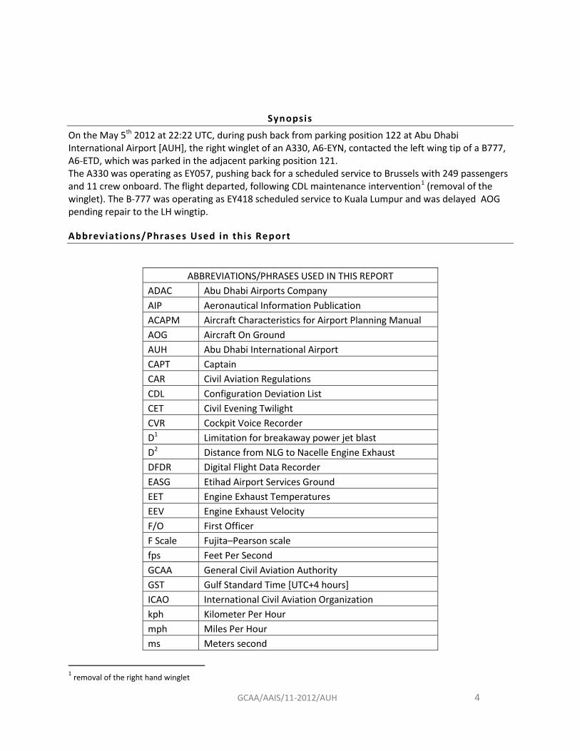
Breakaway Power - Engine Exhaust Velocities
Engine breakaway power tables and charts can be located in the manufacturers Aircraft Characteristics for Airport Planning Manual [ACAPM] for all aircraft types using parking stands 121,122,123.
The examples used here are from the Airbus A330, ACAPM §6/ Operating Conditions.
The three engine types available on the Airbus A330 are available for breakaway power engine exhaust velocity calculation, for example:
• Breakaway Power - GE CF6-80E1 series engine • Breakaway Power - RR Trent 700 series engine • Breakaway Power - PW 4000 series engine
Additional charts are available for Engine Exhaust Temperatures [EET] and Engine Exhaust Velocities for all power ranges, for all three engine types
The specific EEV that relate to the safety case for taxiing in the specific example are the Breakaway Power tables as below. Note: There are two EEV flux streams, one from each engines. The combined span of both engine flux fields should be used in the risk assessment for the safety case.
GCAA/AAIS/11-2012/AUH 11
Figure 5: Breakaway Power - Engine Exhaust Velocities [RR Trent]
1.7 Meteorological Information
At the time of the event, it was dusk with no other meteorological conditions affecting the pushback operation.
1.8 Aids to Navigation
No relevant to this investigation
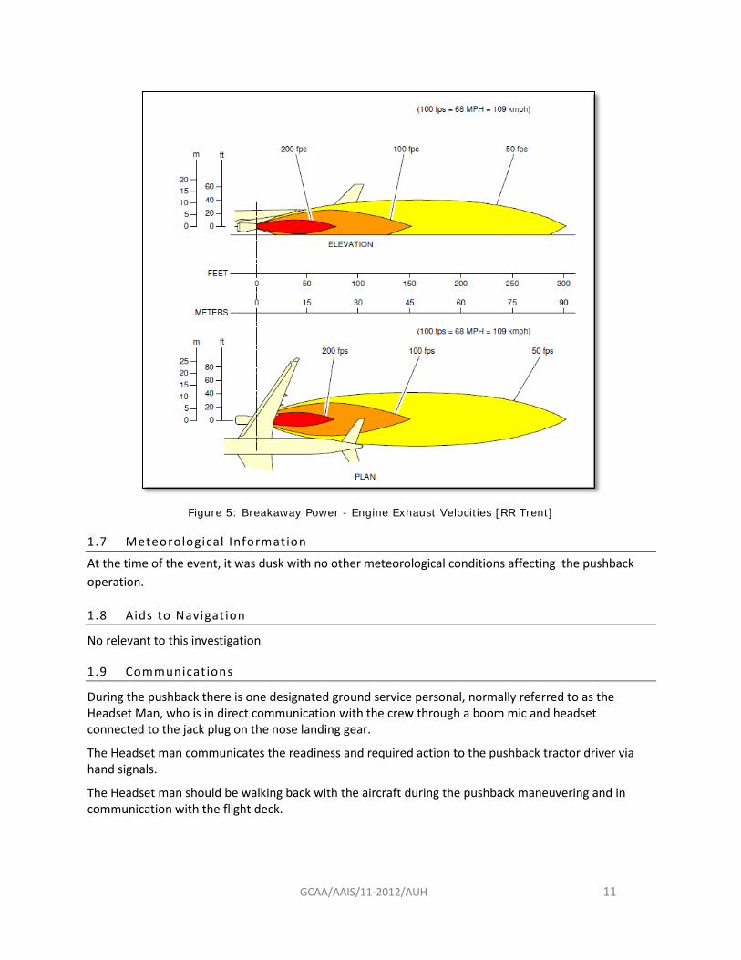
1.9 Communications
During the pushback there is one designated ground service personal, normally referred to as the Headset Man, who is in direct communication with the crew through a boom mic and headset connected to the jack plug on the nose landing gear.
The Headset man communicates the readiness and required action to the pushback tractor driver via hand signals.
The Headset man should be walking back with the aircraft during the pushback maneuvering and in communication with the flight deck.

GCAA/AAIS/11-2012/AUH 12
1.10 Aerodrome Information
The radial parking stands
Historically, the category of aircraft assigned to the parking bays at stand 121/122/123 has altered. There has been a progressive increase in the size category of aircraft parked at the stands as the airport capacity has increased and the volume of passengers and number of flights has increased in relation to the airport volume but not the capacity to handle the increased flight numbers.
The parking stands has several alterations to the push back guide lines/indictors, with several guide lines either removed or the position altered. The stand use has altered over time as the aerodrome has increased movements operationally, while the availability of parking stands remained constant, several alterations to the type, number and category of aircraft using the stands has occurred.
Pushback Procedure
From parking stand 122, it is the ground handlers accepted practice that the pushback tractor driver turns the aircraft off the nominal pushback radial towards parking stand 121 to prevent the rear of the aircraft from obstructing the perimeter road and to prevent jet blast from the aircraft engine start causing an interference with the vehicular traffic using the perimeter road.
ICAO Annex 14 Clearance distances on aircraft stands
3.13.6 Recommendation.— An aircraft stand should provide the following minimum clearances between an aircraft using the stand and any adjacent building, aircraft on another stand and other objects: CAR PART IX, APPENDIX 8 APP 8-29 8.6.5 Clearance Distances on Aircraft Stands 8.6.5.1 An aircraft stand shall provide the following minimum clearances between an aircraft using the stand and aircraft on another stand, any adjacent building, and other objects:
Code Letter Clearance [m] A 3 B 3 C 4.5 D 7.5 E 7.5 F 7.5
8.6.5.2 Where the Code Letter is D, E or F, these clearances may be reduced at a nose-in aircraft stand provided with azimuth guidance by a visual docking guidance system provided that the aircraft stand is a power in push back configuration and; under no circumstances shall the clearance distances be less than: a) 7.5 m between two adjacent aircraft; b) 2 m between any fixed passenger bridge, and the nose of an aircraft; or c) 3.75 m between any object (excluding other aircraft) and the aircraft over any portion of the stand, provided that all obstacles are clear of the engine ingestion danger area.

GCAA/AAIS/11-2012/AUH 13
Jet Blast
A jet blast deflector (JBD) or blast fence is a safety device that redirects the high energy exhaust from a jet engine to prevent damage or vehicle interference
During taxiing the engines of commercial aircraft generate jet blast. If at existing aircraft positions or taxiways new aircraft types are planned for authorization, it is to be examined whether existing safeguard measures are sufficient against the increased jet blast.
Basis of the analyses is the ‘35 mph jet blast isotach’, which is provided for each type of aircraft by the manufacturer. Due to the restrictive space situation in the terminal area it is often difficult to fulfil these requirements.
The 35 mph jet blast isotach is the baseline used for airport planning where jet blast above this value can have a detrimental effect on surrounding structures, airside vehicles and air stairs and ground handling personnel.
Figure 6 Engine Exhaust Velocities/Ground Idle Power - RR Trent 700 series engine
100 fps = 68 mph = 109 kph 50 fps = 34 mph = 55 kph

GCAA/AAIS/11-2012/AUH 14
Fujita Scale[F Scale] or Fujita–Pearson Scale
Figure 7 Fujita scale (F-Scale), or Fujita–Pearson scale
Vehicular movement around aerodromes particularly airside in the movements, maneuvering or apron, ramp or tarmac areas is inherently hazardous due to the proximity of service roads and the jet efflux from aircraft engines.
Aerodrome vehicular traffic transiting areas of risk of jet blast pose several problems for safe and effective safety management due to the risk of vehicle sliding or for large sided service vehicles the rsik is tipping over.
The nominal jet blast value for airside traffic movement is 35mph/50 fps.
The values for vehicular tipping points under extreme high wing velocities can be found in the Fujita–Pearson scale.
GCAA/AAIS/11-2012/AUH 15
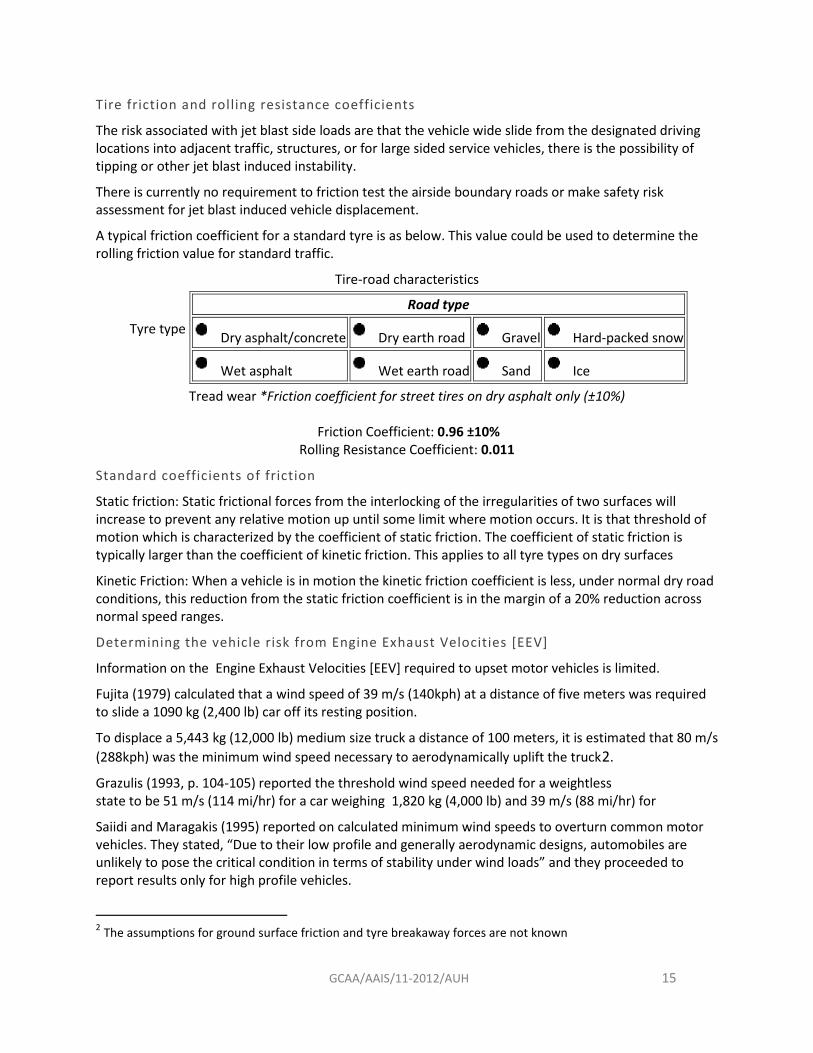
Tire friction and rolling resistance coefficients
The risk associated with jet blast side loads are that the vehicle wide slide from the designated driving locations into adjacent traffic, structures, or for large sided service vehicles, there is the possibility of tipping or other jet blast induced instability.
There is currently no requirement to friction test the airside boundary roads or make safety risk assessment for jet blast induced vehicle displacement.
A typical friction coefficient for a standard tyre is as below. This value could be used to determine the rolling friction value for standard traffic.
Tire-road characteristics
Tyre type
Road type
Dry asphalt/concrete Dry earth road Gravel Hard-packed snow
Wet asphalt Wet earth road Sand Ice
Tread wear *Friction coefficient for street tires on dry asphalt only (±10%)
Friction Coefficient: 0.96 ±10% Rolling Resistance Coefficient: 0.011
Standard coefficients of friction
Static friction: Static frictional forces from the interlocking of the irregularities of two surfaces will increase to prevent any relative motion up until some limit where motion occurs. It is that threshold of motion which is characterized by the coefficient of static friction. The coefficient of static friction is typically larger than the coefficient of kinetic friction. This applies to all tyre types on dry surfaces
Kinetic Friction: When a vehicle is in motion the kinetic friction coefficient is less, under normal dry road conditions, this reduction from the static friction coefficient is in the margin of a 20% reduction across normal speed ranges.
Determining the vehicle risk from Engine Exhaust Velocities [EEV]
Information on the Engine Exhaust Velocities [EEV] required to upset motor vehicles is limited.
Fujita (1979) calculated that a wind speed of 39 m/s (140kph) at a distance of five meters was required to slide a 1090 kg (2,400 lb) car off its resting position.
To displace a 5,443 kg (12,000 lb) medium size truck a distance of 100 meters, it is estimated that 80 m/s (288kph) was the minimum wind speed necessary to aerodynamically uplift the truck2.
Grazulis (1993, p. 104-105) reported the threshold wind speed needed for a weightless state to be 51 m/s (114 mi/hr) for a car weighing 1,820 kg (4,000 lb) and 39 m/s (88 mi/hr) for
Saiidi and Maragakis (1995) reported on calculated minimum wind speeds to overturn common motor vehicles. They stated, “Due to their low profile and generally aerodynamic designs, automobiles are unlikely to pose the critical condition in terms of stability under wind loads” and they proceeded to report results only for high profile vehicles.
2 The assumptions for ground surface friction and tyre breakaway forces are not known

GCAA/AAIS/11-2012/AUH 16
Minimum Overturning Wind Speeds
(perpendicular to the vehicle) Vehicle Type
24 ms/78fps/85kph 5.5 m travel trailer, 29 ms/95fps/104kph 9 m motor home 33 ms/108fps/117kph 13,600 kg 20m semi-trailer 45 ms/147fps/162kph 5 m camper van
Calculated minimum overturning wind speed for a minivan is considered to be the following
53 ms/173fps/119mph/190 kph
s
Figure 8 Typical Minivan Dimensions
Figure 9 Overview Engine Exhaust and the Perimeter Road Boundary
A330 Jet Blast : Scale approximate
Perimeter road
Stand 122
N
GCAA/AAIS/11-2012/AUH 17
1.11 Fl ight Recorders
The Cockpit Voice Recorder [CVR] was removed and downloaded by the GCAA. As the engines of the A330 had not been started, no DFDR information was available to download.
1.17 Organisat ional and Management Information
There was a confused response from the Operator, Abu Dhabi Airports Company [ADAC] and Etihad Airport Services Ground (EASG)] regarding who was responsible to notify the GCAA Air Accident Duty Investigator on the GCAA 24/7 hotline number.
A review of the organizational accident notification process produced a finding regarding responsibility to notify an occurrence.
At the time of the serious incident, the ground handling company was an independent commercial entity known as Abu Dhabi Airport Services [ADAS].
The ground handling services at Abu Dhabi International Airport are now handled by Etihad Airport Services Ground (EASG): Etihad Airport Services LLC (EAS) is the Etihad Airways holding company established to further enhance airport services, ground handling and cargo operations at Abu Dhabi International Airport following the airline’s strategic acquisition of the three airport services companies, Abu Dhabi Airport Services (ADAS), Abu Dhabi In-Flight Catering (ADIFC) and Abu Dhabi Cargo Company (ADCC).
All Safety Recommendations related to ground handling previously managed by ADAS are referred to the existing entity known as Etihad Airport Services Ground (EASG) through the ground handling accountable manager.
1.18 Addit ional Information
No additional factors have been determined

GCAA/AAIS/11-2012/AUH 18
2 Analysis
Terminal one, Stand 122
Figure 10: AUH T1 Stand 122
Overview of the parking stand position and location.
Figure 11 Stand 121/122 CAD Simulation
An airport planner computer model of the aircraft positions and wingtip clearance distances
Stand 122
N24°25’38.86”
E54°38’ 52.23”
Taxiway

GCAA/AAIS/11-2012/AUH 19
The pushback manoeuvre used for this stand
Figure 12 PathPlanner3 optimal push back radial from T1/stand 122
If the A330-200 is pushed back towards the taxi lane center-line in such a way that the main landing gear follows the lead-in line on Stand 122, there is no collision risk and adequate wingtip clearance is achieved.
Consequently, the A330-200 wingtip track (red) is at a distance of ~13m from the 777-300ER wingtip. This wingtip margin is well above the ICAO value of 7.5m.
For this wingtip collision to occur the A330 -200 Main Landing Gear centroid has to have been approximately 13meters off-track displaced to the starboard [right-side].
The pushback practice of displacing the pushback center-line to the tractor drivers left and beginning a progressive aircraft turn to the drivers right-hand side was not an approved or documented practice with no signalling of turn initiation points predefined.
The driver initiates the turn based on judgment with experience of the stand and from previous pushback exercises.
The drivers view of the wingtips is limited when seated and in low ambient light conditions.
3 PathPlanner is a CAD based software for airside planning, design and operations.

GCAA/AAIS/11-2012/AUH 20
Photo 2 - Push back drivers View
A wing walker was not employed, although several ground handling personnel who judged that a collision was probable did attempt to communicate with the driver and headset man. The headset man sitting in the tractor can, facing away from the pushback direction was a contributing cause to this incident.
Jet blast protection
Jet-Blast Deflectors, Blast Screens and Blast Fences are effective and easily installed jet blast mitigation installations that allow unrestricted traffic access to boundary roads airport service roads.
Figure 13 Jet Blast Deflectors

GCAA/AAIS/11-2012/AUH 21
Code E aircraft Engine Exhaust Velocities [EEV]
Based on the published data it is improbable a stationary vehicle will be upset by winds on the vehicle of less than 52 m/s (115 mph). The probability of upset, and therefore the percentage of vehicles upset, will increase as wind speed increases above 52 m/s (187kph). At some wind speed, perhaps greater than 81 m/s (291kph), most vehicles in the wind field will be upset.
Air Velocity Distribution Behind Wing-Mounted Aircraft Engines4 has been modeled for deicing trucks using verified field data to determine tipping values. Although useful , the instability of the de-icing trucks due to the extended booms and a high center of gravity configuration do not accurately reflect the probability of vehicular displacement due to side loads from jet blast.
Based on published data, the Fujita Scale or F Scale EEV limitations are minimum acceptable requirements used to determine the roll over wind velocity required to tip a motor vehicle only.
Minimum Safe Distance
Based on the published engine data for a maximum EEV flux velocity of 50 fps/55 kph, the minimum safe distance an Airbus A330-200 can be released from the pushback tug for a safe engine start and application of breakaway power is 112.18 meters from the boundary road centerline.
EEV Distance Minimum Safe Distance [m]
fps kph D1 meter D2 NLG 50 54.864 90 +22.18 112.18
Unsafe Distance 100 110 45 +22.18 67.18
Table 1 Minimum Safe Distance5
The current release point is 124 meters from the EEV source. The NLG position is 146 meters from the boundary road centreline, this is the current release point.
Predefined Pushback Tug Release Points
Based on the ACAPM, to achieve the 50 fps limitation for breakaway power jet blast, a minimum of 112 meters
4 Prepared for Transportation Development Centre On behalf of Civil Aviation Transport Canada October 1999/Ref TP 13480E 5 D1 – distance from engine to 50 fps limit. D2 – Distance from NLG to engine exhaust datum.

GCAA/AAIS/11-2012/AUH 22
Figure 14 Tug Release Point
The Pushback Tug Release Point for stands 123 and 122 should be the isotach minimum, with an added factor of safety of 20% to allow for non-standard breakaway power application.
112 m
Pushback Tug Release Point
Boundary Road
Factor of safety = 134 m

GCAA/AAIS/11-2012/AUH 23
Cockpit Voice Recorder
Following the request to quarantine the CVR and the download at the GCAA Data Laboratory, the data retrieved was not consistent with the known sequence of events. Several verification tests were performed with the results indicating that the CVR may have been erased for the time frame between the master battery switch was turned on, until just following the pushback collision.
The CVR recording begins after the event.
The CVR cannot be accidently erased as there are several deliberate actions required by the crew or ground engineer which are sequential.
Operator and Aerodrome Notification Procedures
The GCAA Air Accident Investigation Duty Investigator was not notified of this event until approximately ten hours after the incident occurred.
The cause of the delayed notification of the event from the airport ground handler, airport safety department and the aircraft operator was due to no clear definition in the respective safety organizations regarding who was responsible to report the incident.
Clarification of the reporting structures and notification procedures is section 4. Safety Recommendations
The Aircraft operators, ground handlers and airport operator’s procedures and regulatory framework for refueling with passengers embarking, on board or disembarking
Wing walkers are not used for the pushback from this parking stand. The minimum 7 meter wingtip to wingtip clearance distance is achieved if the pushback is performed on the correct radial from the pushback stand. Actual, nominal separation distance is 13.4 meters [dry wing] based on a Path planner analysis
Photo 3 Cockpit View After Wingtip Contact looking forward
Lead-in line PB 122

GCAA/AAIS/11-2012/AUH 24
3. Findings, Causes and Contributing Factors
The following findings, causes and contributing factors were made with respect to this Serious Incident.
To serve the objective of this Investigation, the following sections are included in the “Conclusions” heading:
• Findings. Are statements of all significant conditions, events or circumstances in this Serious Incident. The findings are significant steps in this Serious Incident sequence, but they are not always causal or indicate deficiencies.
• Causes. Are actions, omissions, events, conditions, or a combination thereof, which led to this Serious Incident.
• Contributing factors. Are actions, omissions, events, conditions, or a combination thereof, which, directly contributed to this Serious Incident and if eliminated or avoided, would have reduced the probability of this Serious Incident occurring, or mitigated the severity of its consequences.
Findings
• The accident happened at 22:21 UTC [ 02:21 GST] • The GCAA Air Accident Duty Investigator hot line number was not notified of the occurrence
until ten hours after the event occurred. • The Satellite stands are in compliance with GCAA CAR PART IX, APP 8-29 8.6.5 Clearance
Distances on Aircraft Stands. • The clearance distance between the two adjacent parked aircraft when parked nose in on the
stand lead in lines was between 11.24m and 13m based on the aircraft geometry and computer simulations.
• The pushback team at the time of the accident was comprised of a push back tug driver and a headset man.
• The pushback tug driver and the headset man were properly qualified and licenced to conduct the pushback
• The surface weather reported for AIDA on the morning of the event was clear, with minimum visibility of 8000m
• The A330 wing span can vary marginally based on the fuel load – dry wing/wet wing • No wing walker was required for this stand unless requested by the headset man. • The drivers peripheral view from the DOUGLAS-KALMAR towbarless aircraft tractor TBL-
280Mk4 is limited from the sitting position ahead of the nose landing gear. • All communication between the pushback driver and the headset man, or a wing walker if
required, is through hand signals only. • The ground surface markings at the stands have been altered several times with confusing
pushback markings when operating under low light conditions. • At the time of the incident there was no illuminated or reflective markings for the lead-in lines
to the stand • The low level of illumination under the aircraft forward fuselage, confusing lead in marking
alterations and poor surface definition during twilight operations do not provide sufficient guidance or cues to the pushback driver.
• The headset man was sitting in the pushback tug and not walking back with the aircraft is a non-compliance with the Etihad Airways TPM.

GCAA/AAIS/11-2012/AUH 25
• The pushback tug seat faces in the opposite direction of travel of the pushback tug. • There is a lack of standardisation between the EASG procedures manual and the Etihad Airways
TPM for aircraft pushback Standard Operating Procedures [SOP] • No pushback briefing is required prior to push back in the SOP in effect at the time of the
accident. • Clear lines of responsibility and delineation of duty are not adequately established in the SOP’s. • There is no established leadership in the pushback team between the driver and headset man
who both work in cooperation without a clearly defined hierarchy. • No defined risk assessment has been performed to determine the safe pushback and engine
start distance from the terminal one perimeter road to avoid engine exhaust problems with road vehicle traffic.
• No verifiable aerodrome data is available for safe engine exhaust velocity [EEV]side loads on aerodrome vehicular traffic. The impact of severe EEV on single vehicle traffic should be obtained on as many vehicles as possible within the aerodrome to define a safety case.
• No jet blast protection barriers are installed between the taxiway at parking stands 121/122/123 at Terminal one and the affected boundary road.
• The silent pushback procedure determines the pushback turn method of turning the aircraft early before passing the adjacent aircraft’s wingtip. This procedure was established release the aircraft further up the taxiway to avoid possible problems with jet blast on the boundary road.
Causes
• The pushback procedure required to position the aircraft to avoid jet blast interference with the boundary road
• Nonstandard pushback procedure used to position the Airbus A330 on the taxiway • No wing walker used to manage the wingtip clearance risk. • No lead in lights on the taxi way to assist the tractor driver during pushback
Contributing factors
• Standard working practice on the silent starts to turn the aircraft early to avoid engine exhaust velocity problems with the boundary road vehicular traffic.
• No jet blast protection is provided for the boundary road adjacent to parking stands 121/122/123.
• Poor surface definition and confusing pushback markings • No clear pushback team organization • Headset man sitting in the pushback tractor can facing in the opposite direction of travel • Jet blast risk mitigation not clearly defined

GCAA/AAIS/11-2012/AUH 26
4. Safety Recommendations
The following Safety Recommendations are referred to the current ground handling entity Etihad Airport Services Ground (EASG), the operator, Etihad Airways and the aerodrome management, Abu Dhabi Airports Company (ADAC).
• GCAA Safety Recommendation #08/2013
EASG and Etihad to Standardize SOP’s for pushback operation, to include the following requirements:
i Push back team composition to be agreed as a Standard Operating Unit [SOU] ii Develop an SOP for a pre-pushback briefing with clear delineation of team
responsibilities and communication. This shall include establishing the team leader identification for the pushback.
iii Perform a risk assessment of parking stands where non-standard pushback operations are normal procedure and establish the requirement for a wing walker if required.
iv The wing walker and tractor driver to be in radio communication, or the wing walker is equipped with an aural warning device to alert the tractor driver of a potential conflict.
v Develop Standard and Non-standard pushback procedures for all parking stands. Include in an SOP.
• GCAA Safety Recommendation #09/2013
The ADAC safety department, EASG, Etihad and the ANS provider should jointly develop a prescriptive procedure for Non Standard Pushbacks [NSP], which should also address the training and competence of the ground handling personnel responsible for conducting push back manoeuvring.
This procedure shall be applied using the pushback simulator as part of the driver approvals procedure.
• GCAA Safety Recommendation #10/2013
Lead in lights or reflectors to be installed to clearly illuminate the lead-in lines complaint with ICAO Annex 14/GCAA CAR Ops.
• GCAA Safety Recommendation #11/2013
A short term specific SOP to be defined for a silent pushback, where no turns are permitted until after the wing tip has passed the adjacent parked aircraft if the risk of a conflict cannot be reduced. This SOP can be modified or deleted based on the safety and risk assessment in SR#5.
• GCAA Safety Recommendation #12/2013
ADAC to develop and implement a Tug Release Point (TRP) procedure for all ADAC Airports to ensure safe and effective pushbacks.
This shall include the determination of the minimum acceptable distance for engine start from the perimeter road from parking stands 121,122,123 for all ICAO code aircraft using these parking stands .

GCAA/AAIS/11-2012/AUH 27
If a minimum acceptable distance cannot be determined through a defined risk assessment process, a mitigation procedure is to be established that allows for a straight pushback from parking stands 121,122,123 and turn on to the taxi way and engine start.
Predetermined areas for a full stop tug release shall be established considering all wingtip clearance and jet blast issues.
This mitigation process shall include a safety assessment for jet blast for the operational requirements of the pushback/engine start and the users of the adjacent perimeter/boundary road.
This recommendation shall include quantified aerodrome data for safe engine exhaust velocity [EEV]side loads on aerodrome vehicular traffic. The impact of severe EEV on single vehicle traffic should be obtained on as many vehicles as possible within the aerodrome to define the safety case.
If no acceptable safety case can be determined, ADAC are to install jet blast protection barriers on service and boundary roads affected by engine starting when pushing back from parking stands 121,122,123.
• GCAA Safety Recommendation #13/2013
Etihad to revise the flight crew the SOP to avoid deliberate or accidental erasure of the CVR following an event.
• GCAA Safety Recommendation #14/2013
Aerodrome Operator and relevant airside stakeholders to review GCAA CAR Part IX, CAR Part X and CAAP 50 SMS to ensure the correct Hazard Identification and Risk Assessment process is being applied to all aircraft pushbacks.
• GCAA Safety Recommendation #15/2013
Abu Dhabi Airports Company [ADAC] aerodrome safety management department and Abu Dhabi Airports Services [EASG] ground handler safety organisation is to review their notification of incidents/accidents procedures to include the CAR Ops requirement to notify the GCAA Duty Investigator Hotline number immediately an event occurs. Each organisation is to provide the GCAA with the updated procedure within thirty days of receiving this recommendation.
• GCAA Safety Recommendation #16/2013
Etihad, EASG and ADAC to update and implement their respective Safety Management Systems [SMS] to include pushback risk assessment, ground handling crew coordination and risk mitigation for jet blast at Terminal one.
• GCAA Safety Recommendation #17/2013
ADAC to friction test the boundary road and determine using standard industry data the risk of vehicular displacement from jet blast at or above the 35mph Isotach limit

GCAA/AAIS/11-2012/AUH 28
Contact Information
Air Accident Investigation Sector P.O.BOX: 6558 ABU DHABI - UNITED ARAB EMIRATES TEL: +971 2 444 7666 FAX:+971 2 449 1599 E-mail: [email protected]
Web: http://www.gcaa.gov.ae/en/departments/airaccidentinvestigation/pages/default.aspx