“Aiming for Energy Conservation in Hydrogen Manufacturing ...
16
National Convention of Excellent Examples in Energy Conservation for Fiscal 2008 2008_RDGRB_4_Idemitsu_Kosan_Co.,_Ltd._Chiba_Refinery 1 “Aiming for Energy Conservation in Hydrogen Manufacturing Equipment” Idemitsu Kosan Co., Ltd. Chiba Refinery Refining Section 1 Project B Group ◎ Keywords: Rationalization of fuel combustion ◎ Outline of Theme In petroleum refining facilities, hydrogen is supplied by hydrogen manufacturing equipment which uses a steam reforming method to create hydrogen as the main product, and by catalytic reforming equipment that manufactures hydrogen as a byproduct of aromatic compounds. In recent years, the increasing shift to sulfur-free petroleum products t has progressed and there is a trend to use increasing amounts of hydrogen, so that the operation of the hydrogen manufacturing equipment, which consumes a huge amount of energy, has been increasing. Accordingly, by reviewing the hydrogen manufacturing equipment, recovery equipment, and the overall system consumption equipment, together with reducing the operation of hydrogen generating equipment by restoring the performance of the recovery equipment and making effective use of low purity hydrogen, we realized a large energy conservation. ◎ Implementation Period for the said Example March 2007 – April 2008 (Total of 13 months) Project Planning Period March 2007 – January 2008 (Total of 10 months) Measures Implementation Period January 2008 – February 2008 (Total of 1 month) Measures Effect Confirmation Period February 2008 – April 2008 (Total of 2 months) ◎ Outline of the Business Establishment Items Produced LPG, naphtha, gasoline, kerosene, diesel, fuel oil, and lubrication oil No. of Employees 565 persons (As of April 1, 2007) 2008 Prize of Director General of Regional Bureau of Economy, Trade and Industry
Transcript of “Aiming for Energy Conservation in Hydrogen Manufacturing ...

National Convention of Excellent Examples in Energy Conservation for Fiscal 2008 2008_RDGRB_4_Idemitsu_Kosan_Co.,_Ltd._Chiba_Refinery
1
“Aiming for Energy Conservation in Hydrogen Manufacturing Equipment”
Idemitsu Kosan Co., Ltd. Chiba Refinery
Refining Section 1 Project B Group
◎ Keywords: Rationalization of fuel combustion
◎ Outline of Theme
In petroleum refining facilities, hydrogen is supplied by hydrogen manufacturing equipment
which uses a steam reforming method to create hydrogen as the main product, and by
catalytic reforming equipment that manufactures hydrogen as a byproduct of aromatic
compounds. In recent years, the increasing shift to sulfur-free petroleum products t has
progressed and there is a trend to use increasing amounts of hydrogen, so that the
operation of the hydrogen manufacturing equipment, which consumes a huge amount of
energy, has been increasing.
Accordingly, by reviewing the hydrogen manufacturing equipment, recovery equipment, and
the overall system consumption equipment, together with reducing the operation of
hydrogen generating equipment by restoring the performance of the recovery equipment
and making effective use of low purity hydrogen, we realized a large energy conservation.
◎ Implementation Period for the said Example
March 2007 – April 2008 (Total of 13 months)
Project Planning Period March 2007 – January 2008 (Total of 10 months)
Measures Implementation Period January 2008 – February 2008 (Total of 1 month)
Measures Effect Confirmation Period February 2008 – April 2008 (Total of 2 months)
◎ Outline of the Business Establishment
Items Produced LPG, naphtha, gasoline, kerosene, diesel, fuel oil, and
lubrication oil
No. of Employees 565 persons (As of April 1, 2007)
2008 Prize of Director General of Regional Bureau of Economy, Trade and Industry

National Convention of Excellent Examples in Energy Conservation for Fiscal 2008 2008_RDGRB_4_Idemitsu_Kosan_Co.,_Ltd._Chiba_Refinery
2
Annual Energy Usage Amount (Actual results for fiscal year 2006)
Fuel, etc. (Crude Oil Equivalent) 965,000 kL
Electric Power 593,859 MWh
◎ Overview of Target Facilities
In the refinery and plant, there are three types of hydrogen, which differ according to the
generation equipment, pressure, and purity.
a) 15 kilo Hydrogen: Pressure 1.5MPa, High Purity
General hydrodesulfurizationapplications, polymer applications, etc.
b) 25 kilo Hydrogen: Pressure 2.5MPa, High Purity
Plant hydrodesulfurizationapplications, etc.
c) Reformer Hydrogen: Pressure 2.5MPa, Low Purity
Indirect desulfurization equipment,
Deep desulfurization equipment applications
Each type of hydrogen is linked between the generation equipment and consumption
equipment by pipeline. This time, by eliminating the impurities in the low purity reformer
hydrogen generated by the Naphtha Catalytic Reforming Equipment (known below as the
2P Equipment), and taking the main target improvement equipment as the Hydrogen
Recovery Unit (known below as the HRU Equipment) which recovers hydrogen to high
purity 15 kilo hydrogen together with the Hydrodesulfurization Equipment, it was aimed to
indirectly reduce the operation of the Hydrogen Manufacturing Equipment (known below as
the HY Equipment).
Fig. 1 The Process Chart of the Facility
25 kilo Hydrogen To Plants
15 kilo Hydrogen
Reformer Hydrogen
Fuel Gas
Light Naphtha Reforming Equipment
(LNR Equipment)
Naphtha Catalytic Reforming Equipment
(2P Equipment)
Hydrogen Manufacturing Equipment
(1HY Equipment)
Hydrogen Recovery Unit
(HRU Equipment)
HydrodesulfurizationE
quipment

National Convention of Excellent Examples in Energy Conservation for Fiscal 2008 2008_RDGRB_4_Idemitsu_Kosan_Co.,_Ltd._Chiba_Refinery
3
1. Reasons for Theme Selection
Our section is responsible for comprehensively
managing the on-premises balance between the
hydrogen generation and consumption.
Responding to the hydrogen consumption amount,
this section undertakes the role of maintaining the
hydrogen balance by carrying out HY equipment
operation adjustment and HRU equipment
operation adjustment.
The on-premises hydrogen balance continues to become tighter due to the recent increase
in hydrogen-consuming applications in petroleum refining and the chemical industry.
Regarding the periods where the adjoining plants’ regular maintenance coincides with the
hydrogen generation equipment’s regular maintenance periods, the receiving of hydrogen
becomes extremely restricted, and the influence on operations is becoming larger.
Additionally, this large fuel-consumption equipment taking up 17% of the section’s fuel
consumption is also equipment that emits very large amounts of carbon dioxide, and so it is
desirable to restrict its operation as far as possible.
However, the supply of hydrogen is one of the most important elements for the stable
operation of the refinery and plants, and in view of our mission of providing a stable supply
the positive implementation of energy conservation activities is also a difficult issue.
Accordingly, rather than just considering the HY equipment by itself, we considered the
entire hydrogen supply system, and as one part of the performance-maintaining activities
implemented throughout all the facilities we tackled the reduction in fuel consumption of the
HY equipment by devising various measures to allow reduction of the HY equipment
operation.
2. Understanding and Analysis of Current Situation
(1) Understanding of Current Situation
1) Hydrogen balance in the refinery and plant
As the hydrogen generating sources, there are the following three main types of equipment.
① Hydrogen manufacturing equipment This equipment uses the steam reforming method to manufacture hydrogen as the main
product, using naphtha, methane and butane as fuels. It generates (a) 15 kilo high purity
HY Equipment 17%
Fig. 2 Percentage of Fuel Amounts Used in this Section

National Convention of Excellent Examples in Energy Conservation for Fiscal 2008 2008_RDGRB_4_Idemitsu_Kosan_Co.,_Ltd._Chiba_Refinery
4
hydrogen.
② Light naphtha reforming equipment This equipment reforms light naphtha to manufacture benzene, creating (a) 15 kilo high
purity hydrogen as a byproduct.
③ Naphtha catalytic reforming equipment This reforms heavy naphtha to manufacture BTX, creating (c) 25 kilo low purity hydrogen as
a byproduct. The amount of hydrogen generated as a byproduct from the light naphtha
manufacturing equipment (known below as LNR equipment) is roughly constant throughout
the year.
While most of the (a) 15 kilo hydrogen is supplied to the refinery desulfurization equipment,
a part has its pressure raised using a compressor in order to cover for insufficiencies in the
25 kilo hydrogen.
The (c) 25 kilo low purity hydrogen has limitations in its usage destinations due to purity
restrictions. Accordingly, it is being recovered as 15 kilo hydrogen by increasing the purity
using the HRU equipment. However, the part of the low purity hydrogen that cannot be
processed due to exceeding the processing capacity can only be utilized as fuel gas. In
addition, from the point of view of controlling the hydrogen pressure, there was a situation
where part of the hydrogen could only be used as fuel gas.
Fig. 3 Hydrogen Balance in the Refinery and Plant
2) HY equipment operation
In the HY equipment, water and hydrocarbons are reacted, reforming them to hydrogen and
carbon dioxide. This reaction is an endothermic reaction that uses a large amount of fuel.
The HY equipment fuel intensities gradually decrease with the operation rate increase (Fig.
4), reaching maximum efficiency at the maximum operation rate.
25 kilo Hydrogen To Plants
15 kilo Hydrogen
Reformer Hydrogen (25 kilo low purity hydrogen) Fuel Gas
Light Naphtha Reforming Equipment
(LNR Equipment)
Naphtha Catalytic Reforming Equipment
(2P Equipment)
Hydrogen Manufacturing Equipment
(1HY Equipment)
Hydrogen Recovery Unit
(HRU Equipment)
Hydrodesulfurization
Equipment

National Convention of Excellent Examples in Energy Conservation for Fiscal 2008 2008_RDGRB_4_Idemitsu_Kosan_Co.,_Ltd._Chiba_Refinery
5
On the other hand, the fuel usage amount rises proportionally to the operation rate (Fig. 5).
Because the fuel usage amount becomes 160 COE-L for each 1 kNm3 of hydrogen
generated, the reduction of this equipment’s operation will be linked with a large energy
conservation effect.
Since this equipment is used for absorbing variations in hydrogen supply throughout the
entire refinery, it is desirable also from the point of view of stable supply that a surplus
should be maintained in the operation to cover the range of stable operation. The current
operation rate is reaching an average of 82%, and it was desired from the points of view
both of fuel usage and also of stable operation for the operation rate to be reduced.
(2) Analysis of Current Situation
In order to reduce the HY equipment operation, it will be necessary to increase the
generation using the equipment that creates hydrogen as a secondary product.
① Increase of byproduct hydrogen due to increased LNR equipment operation
② Increase in usage destinations through direct effective use of byproduct reformer
hydrogen or by increasing the purity
The operation of the LNR equipment in ① is roughly constant, and is difficult to increase.
Because the usage destinations that can directly utilize the low purity reformer hydrogen
generated as a byproduct of the 2P equipment in ② are limited, we understood that it
would be essential to increase the capacity of the HRU equipment.
The specific fuel consumptions of the byproduct reformer hydrogen and the hydrogen
generated by the HY equipment are as shown below. (Table 1) There is a large difference in
the specific fuel consumptionsbetween both pieces of equipment, and it was discovered that
even considering a certain amount of investment, increasing the HRU equipment
Current Average Operation Rate
(82%)
Operation Rate (%)
Spec
ific
Fuel
Con
sum
ptio
n In
dex
Operation Rate (%)
Fig. 4 Operation Rate against Specific Fuel Consumption Index
Fig. 5 Operation Rate against Fuel Usage Amount
Fuel
Usa
ge A
mou
nt [U
nits
/day
]
Fuel Reduction

National Convention of Excellent Examples in Energy Conservation for Fiscal 2008 2008_RDGRB_4_Idemitsu_Kosan_Co.,_Ltd._Chiba_Refinery
6
performance would result in large energy conservation.
Since receiving the Minister of Economy, Trade and Industry Award for our case study the
previous year, this section had been striving to made efforts to understand and restore the
decline in equipment performance, and has been steadily achieving results. Regarding the
HRU equipment, too, there had been concern about the decline in performance, but due to
the problem of the restoration cost it had been left pending. However, it was judged that
restoration would be possible using this intensities difference as the capital, and it was
decided to tackle the implementation of the processing performance improvement.
Table 1 Specific Fuel Consumptionfor the Same Hydrogen Generation Amounts
Equipment Name Specific Fuel Consumption
HY Equipment 160 L HRU Equipment 1.2 L
3. Progress of Activities
(1) Implementation Structure
Regarding the investigation this time, the groups inside the section appointed persons to be
in charge, and activities were implemented. In order that progress would not be delayed,
rules were decided for implementing the measures, such as reporting problem points each
time they were discovered and holding regular meetings. (Table 2)
Table 2 Implementation Structure and Activity Schedule
Planned Actual Meeting
Schedule Person in Charge
Current Situation Understanding
Current Situation Analysis Measure
Investigation Measures
Implementation 1 Measures
Implementation 2
Effect Understanding
2007 2008 April June August October December February April
Theme Selection All Members
All Members
All Members
Sakuma Yamada
Nagano Wakabayashi
Mochitzuki Arai
Kazato Yoshihara

National Convention of Excellent Examples in Energy Conservation for Fiscal 2008 2008_RDGRB_4_Idemitsu_Kosan_Co.,_Ltd._Chiba_Refinery
7
(2) Target Settings
By restoring the HRU equipment processing capacity to its initial design performance and
recovering the maximum byproduct hydrogen, it was aimed to reduce the HY equipment
operations to around 75% and cut the HY equipment energy usage amount by 10%. In
consideration of the effect incurred by the energy balance in the refinery, the target was set
as 4,000 COE-kL/year.
(3) Clarification of the Problem Points
1) Adsorption vessel valve problem
① Outline of equipment The HRU equipment is equipment that absorbs and eliminates hydrocarbon impurities in the
hydrogen using pressure swing adsorption (PSA). The adsorption vessel consists of six
vessels. Through repeating the adsorption of impurities during pressure increases and the
desorption of impurities during pressure decreases, the impurities will be absorbed,
discharged and eliminated to increase the hydrogen purity. (Fig. 6)
Fig. 6 HRU Equipment
② HRU equipment designed processing performance Although the HRU equipment’s designed processing performance is 170kNm3/D, the
maximum processing performancein actual operation was 110 kNm3/D, and there was a
situation where it was not possible to increase the processing amount due to the adsorption
capacity of the adsorptive materials. For this reason, there was a limit of 50-60 kNm3/D on
15 kilo Hydrogen
Reformer Hydrogen
Ads
orpt
ion
vess
el
Fuel Gas
National Convention of Excellent Examples in Energy Conservation for Fiscal 2008 2008_RDGRB_4_Idemitsu_Kosan_Co.,_Ltd._Chiba_Refinery
8
the product’s hydrogen amount.
Here, the capacity is said to be shown by the ratio of the maximum product hydrogen
amount used for raising the pressure in the adsorption vessel to the raw material processing
amount. Further, the coefficient that adjusts the increase or decrease in the product
hydrogen amount used for raising the pressure is shown as the capacity factor. (Fig. 7)
Fig. 7 HRU Capacity Formula
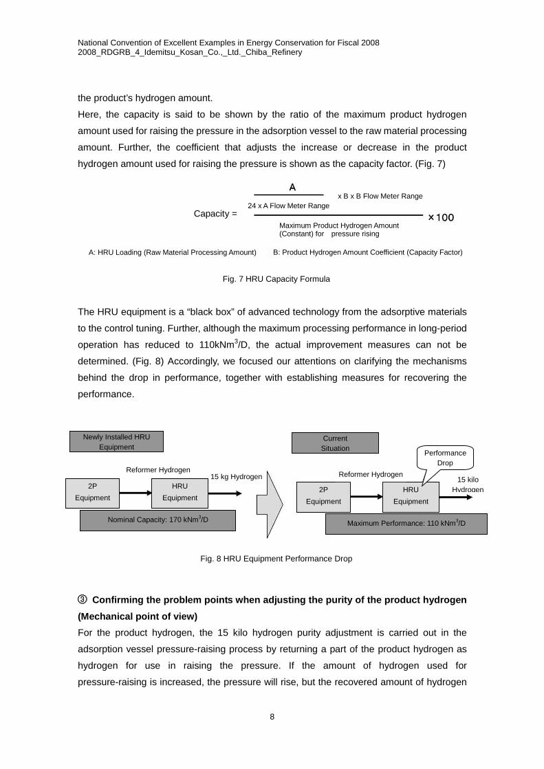
The HRU equipment is a “black box” of advanced technology from the adsorptive materials
to the control tuning. Further, although the maximum processing performance in long-period
operation has reduced to 110kNm3/D, the actual improvement measures can not be
determined. (Fig. 8) Accordingly, we focused our attentions on clarifying the mechanisms
behind the drop in performance, together with establishing measures for recovering the
performance.
Fig. 8 HRU Equipment Performance Drop
③ Confirming the problem points when adjusting the purity of the product hydrogen (Mechanical point of view) For the product hydrogen, the 15 kilo hydrogen purity adjustment is carried out in the
adsorption vessel pressure-raising process by returning a part of the product hydrogen as
hydrogen for use in raising the pressure. If the amount of hydrogen used for
pressure-raising is increased, the pressure will rise, but the recovered amount of hydrogen
Capacity =24 x A Flow Meter Range
x B x B Flow Meter Range
Maximum Product Hydrogen Amount (Constant) for pressure rising
A: HRU Loading (Raw Material Processing Amount) B: Product Hydrogen Amount Coefficient (Capacity Factor)
2P Equipment
HRU Equipment
Newly Installed HRU Equipment
Nominal Capacity: 170 kNm3/D Maximum Performance: 110 kNm3/D
Current Situation
Reformer Hydrogen 15 kg Hydrogen
2P Equipment
HRU Equipment
Reformer Hydrogen 15 kilo
Hydrogen
Performance Drop

National Convention of Excellent Examples in Energy Conservation for Fiscal 2008 2008_RDGRB_4_Idemitsu_Kosan_Co.,_Ltd._Chiba_Refinery
9
will be reduced. Conversely, if there is
less hydrogen, the purity will be
reduced, but the product hydrogen
amount will increase. The pressure in
each of the adsorption vessels repeats
the adsorption and desorption inside
the processes from pressure raising to
pressure lowering, comprising 12
processes. In the situation where the
product hydrogen purity is to be
increased, by operating the adjusting valve shown in the figure at right during the adsorption
vessel pressure-raising process, part of the product hydrogen can be introduced to the
adsorption vessel to increase the amount. (Fig. 9)
If the hydrogen for pressure-raising is increased, the equipment capacity increases and the
HRU equipment processing amount will be reduced. For this reason, the maximum amount
of pressure-raising hydrogen is fixed, and in the situation where the target hydrogen purity
could not be attained, the only thing that could be done was to reduce the overall loading on
the HRU unit (Raw material processing amount).
In particular, the adjusting valve concerned operates 2 million times per year, and in
consideration of the number of operations, this valve requires the adjusting valve to be
regularly replaced. When there were “Adjusting valve problems” or “Pressure setting
problems”, the hydrogen processing amount will be reduced, so investigations were started
and a disassembly inspection of the valve was carried out. As a result of the investigation,
no problems were found either in the valve or the operation condition. The FTA utilized at
that time is shown in Fig. 10.
Purity Adjusting Hydrogen
Introduction Valve
Fig. 9 HRU Equipment Purity Adjustment

National Convention of Excellent Examples in Energy Conservation for Fiscal 2008 2008_RDGRB_4_Idemitsu_Kosan_Co.,_Ltd._Chiba_Refinery
10
Fig. 10 Performance Reduction FTA
Because we had previously understood that the adsorptive materials could be used
semi-permanently, we did not think to consider this so deeply. However, from the above
result we thought that deterioration of the adsorptive materials might be occurring through
repeated long-period use, or there could be deterioration of the adsorptive materials due to
defective storage methods. Accordingly, we investigated the adsorptive materials.
HRU MAX CHG UP Not Possible
HRU CAP 110<
HRU CAP FACTOR UP
PG Octane Value High
2P Reaction Temperature High
Raw Material Hydrogen Purity
Reduction
Product Hydrogen Purity Reduction
Analyzer Problem
Analyzer Breakdown
Pressure Setting Problem
Adsorption Vessel Valve Problem
Adsorption Vessel Valve Leak
Adsorption Vessel Valve SQ Problem
CPU SQ Problem
CPU Problem or Breakdown
Adsorption vessel Adsorptive
materials Problem
(Recovery Rate Reduction)
Adsorptive materials Performance Decline
Impurities Included in Raw Material Gas
Mist Separation Worsening
Inlet Filter Blockage
Raw Material Gas Temperature High
Raw Material Gas Cooler Performance
Reduction
Raw Material Gas Cooler Blockage
Adsorptive materials Deterioration
Adsorptive materials Clogging
Usage Period 20 Years or Longer
Deficiency in the Storage Method
Operation is Irregular
Analyzer Breakdown
Analyzer Problem
Administration is carried out by product testing, and there is no problem.
Regular inspections are being implemented, and there is also no
problem with the accuracy.
CPU poor condition prevents continuation of operation.
Liquid is regularly removed Filter ΔP administration is present.
Regular inspections are being implemented.
A temperature alarm is provided.
Regular inspections are being implemented. There is no problem with the accuracy.
It is possible that there is degradation due to aging.
There is a possibility that tiny amounts of hydrocarbons are
attached.
Leaks and operation problems due to excessive number of operating
times
Evaluation Reason and Current Condition

National Convention of Excellent Examples in Energy Conservation for Fiscal 2008 2008_RDGRB_4_Idemitsu_Kosan_Co.,_Ltd._Chiba_Refinery
11
2) Degradation of the adsorptive materials over time (Chemical point of view)
① Adsorption mechanism of the adsorptive materials The adsorptive materials used in the HRU equipment consist of
a molecular sieve, activated alumina, and activated charcoal.
Depending on the molecular structure, the molecular sieve
effect of the adsorptive materials can selectively adsorb the
hydrocarbons that make up the impurities.
For example, inside the activated charcoal there are small holes
called micropores surrounding the molecules, large holes called
macropores that allow gas to pass in and out, and intermediate
size mesopores. The adsorption capacity will be determined by
the good condition of these pores.
In molecular sieves, by trapping the molecules in a zeolite
framework matching the molecule size, it is possible to select a
molecular sieve that can selectively absorb the required types of
impurities.
Regarding the causes of impediments to the adsorption and
desorption effects of the adsorptive materials, the following
items can be suggested.
② Causes of degradation (a) Pore reductions due to heavy hydrocarbons and gums
(b) Change in properties of the adsorptive materials (Changes in acidity, etc.)
(c) Pore reduction due to adsorptive materials wear
(d) Reduction of fine pores due to adsorptive materials wear, and blockages of fine pores or
rises in pressure due to various kinds of fine particles in the zeolite structure (cage).
Because hydrogen systems are comparatively clean systems, the causes of degradation
are few, although the effects of wear and hydrocarbons can be considered. In the past, there
was a period when the HRU equipment stopped due to the relationship with the hydrogen
balance when there was a hydrogen surplus. At this time, the results of an investigation
found that the reformer hydrogen atmosphere was maintaining a slight pressure.
When storing the absorbing agent, it is undesirable to store it in a condition with the
hydrocarbons still attached. (Currently, the hydrocarbons are displaced using an inert gas
before storage.) The reformer hydrogen includes hydrocarbons in the order of several %,
Micropore
Mesopore
Structure of Activated Charcoal
Zeolite Selective Permeation Image
Various Zeolite Structures (Cage)
Fig. 11 AdsorptionMechanisms

National Convention of Excellent Examples in Energy Conservation for Fiscal 2008 2008_RDGRB_4_Idemitsu_Kosan_Co.,_Ltd._Chiba_Refinery
12
and storing the absorbing agent with these hydrocarbons still attached was believed to be a
cause of the performance reduction.
Accordingly, an actual test run was carried out to confirm the degree of absorbing agent
degradation.
(4) Investigations
1) Adsorptive materials degradation
① Hydrogen recovery rate confirmation test run
The hydrogen recovery rate is shown by the following formula.
Hydrogen Recovery Rate = Product Hydrogen Amount/(Raw Material Hydrogen Amount x
Raw Material Hydrogen Purity/100) x 100
While maintaining the same product hydrogen purity, we changed the raw material hydrogen
purity, raw material processing amount, and product hydrogen amount. When we confirmed
the hydrogen recovery rate, we found the results in the table below.
Although the current hydrogen recovery rate was designed to be around 93%, it was found
that the actual rate was around 87%. Because the hydrogen recovery rate did not change
even when the conditions were changed, we could confirm that degradation of the
adsorptive materials was occurring.
HRU Charge (Raw Material
Processing Amount)
Raw Material Hydrogen Purity
Product Hydrogen Purity
Product Hydrogen Amount
Hydrogen Recovery Rate
101 kNm³/D 60% 98.50% 53 kNm³/D 87.50%
103 kNm³/D 70% 98.50% 62 kNm³/D 86.50%
② Adsorptive materials replacement
Replacement of the entire amount of adsorptive materials in the six adsorption vessels was
carried out. When test operation was implemented, the designed performance processing
amount of 170 kNm3/D was secured, and a surplus was created in the adsorption capacity.
The hydrogen recovery rate was restored to the initial designed amount of 93%, and the
product hydrogen amount increased from 50 kNm3/D before the adsorptive materials was
replaced to 100 kNm3/D after the replacement.
This enabled a 5% reduction in the HY equipment loading. However, only implementing this
measure was not sufficient to achieve the target reduction rate. Accordingly, obtaining
advice from surrounding persons, we focused our attention on the new issue of increasing

National Convention of Excellent Examples in Energy Conservation for Fiscal 2008 2008_RDGRB_4_Idemitsu_Kosan_Co.,_Ltd._Chiba_Refinery
13
the usage destinations of the low purity reformer hydrogen.
2) Effective usage of surplus reformer hydrogen
Because the usage destinations for the low purity reformer hydrogen are limited, the surplus
portion is adjusted by expending it as fuel gas. Even after restoring the performance of the
HRU equipment, there was a condition where approximately 30-40 kNm3/D of reformer
hydrogen was being supplied as fuel gas. The only piece of equipment among our
equipment capable of using this hydrogen was the kerosene and diesel deep
hydrodesulfurization equipment (known below as the 3DH equipment), and the hydrogen
was used mixed with the 15 kilo hydrogen. The 3DH equipment continuously used 50
kNm3/D (Fig. 13), and an investigation was carried out to determine whether it would be
possible to increase this usage amount further.
① Relationship between pressure and hydrogen purity on the desulfurizing reaction The 3DH equipment is hydrogenated desulfurization equipment which adds hydrogen to raw
oil and heats it, using a desulfurizing catalyst to eliminate the sulfur portion. In the
hydrogenation reaction, in general if the hydrogen partial pressure reduces, there will be a
greater chance to have lowering of the desulfurization rate and disposition of carbon
(coking) on the catalyst, causing an adverse affect on the reaction and catalyst lifetimes.
As the causes of the reduction on the hydrogen partial pressure, there is the hydrogen purity
reduction and the reaction pressure reduction. If the low purity hydrogen usage amount is
increased, the hydrogen partial pressure due to the hydrogenation reaction in the 3DH
equipment will be reduced. Accordingly, an investigation was made into the influence of the
catalyst on the hydrogen partial pressure lower limit from the point of view of the reaction
and catalyst performance.
② Alleviation of 3DH equipment operation hydrogen partial pressure In the 3DH equipment hydrogen partial pressure, in the current situation a value 0.5MPa
below the operating value will be the minimum value. Accordingly, we confirmed this with the
specialist division, and had them carry out a simulation of the influence of the hydrogen
partial pressure reduction on the catalyst lifetime. As a result, the effect on the catalyst
lifetime was found to be negligible, and it could be confirmed that there would be no
influence on the catalyst replacement periods. It was found that if the hydrogen partial
pressure could be lowered to the minimum value, the reformer hydrogen would be able to

National Convention of Excellent Examples in Energy Conservation for Fiscal 2008 2008_RDGRB_4_Idemitsu_Kosan_Co.,_Ltd._Chiba_Refinery
14
use an additional 40 kNm3/D, so that all of the fuel gas supply portion could be introduced.
③ Improvement of the pressure control method The adjusting valve for the reformer hydrogen intake has a large capacity large valve and a
small capacity small valve to match the flow amount. Because the expending of the reformer
hydrogen as fuel gas is combined with a pressure adjustment, system changes were made
so that the small valve could be used for pressure adjustmentto allow minute pressure
adjustments to be made. By doing so, all of the hydrogen supplied as fuel gas could be
recovered, and at the same time the hydrogen pressure adjusting sensitivity could also be
improved. (Fig. 13)
Fig. 13 Reformer Hydrogen Balance
4. Details of Measures
(1) HRU Equipment Adsorptive Materials Replacement
The replacement of the entire amount of adsorptive materials filling up the HRU equipment a
desorption vessels (6 vessels) with the latest adsorptive materials was carried out. In
addition, by carrying out day-to-day performance administration of the hydrogen recovery
rate which indicates the degradation of the hydrogen recovery equipment, we could
incorporate this in the system for monitoring the trends in HRU capacity to allow
Reformer Hydrogen Intake Flow Amount Adjusting Valve
Recovery of All the Hydrogen due to the Addition of the Reformer Hydrogen Pressure Adjusting Function
Reformer Hydrogen Intake Flow Amount Adjusting Valve
Pressure Adjustment using the Reformer Hydrogen Pressure Adjusting Valve
Reformer Hydrogen
(Large Capacity Valve)
(Small Capacity Valve)
Reformer Hydrogen 15 kilo Hydrogen15 kilo Hydrogen
(Large Capacity Valve)
(Small Capacity Valve)
30-40 kNm3/D
Fuel Gas
Fuel Gas

National Convention of Excellent Examples in Energy Conservation for Fiscal 2008 2008_RDGRB_4_Idemitsu_Kosan_Co.,_Ltd._Chiba_Refinery
15
visualization of the situation.
(2) Effective Use of Surplus Reformer Hydrogen in the 3DH Equipment, and Pressure Adjustment Improvement
By reviewing the 3DH equipment operation hydrogen partial pressure and making maximum
use of the reformer hydrogen, all of the hydrogen that was previously supplied as fuel gas
could be recovered. In addition, the review of the hydrogen pressure adjusting system
enabled the extraction of hydrogen as fuel gas to be completely halted.
Due to the above improvements, the HY equipment operation could be reduced, and it was
possible to reduce the fuel consumption.
5. Effects Achieved after Implementing Measures
a. Due to the replacement of the HRU equipment adsorptive materials, the product
hydrogen was increased from 50kNm3/D to 100kNm3/D. As a result, the HY equipment
operation rate was reduced from 82% to 77%.
b. In addition, the 3DH equipment reformer hydrogen intake amount was increased from
50kNm3/D to 90kNm3/D. In addition, by improving the pressure adjustment of the fuel gas,
the final HY equipment operation rate became 74%.
Due to the above improvements, the target of reducing the HY equipment energy use by
10% was achieved, and an energy conservation amount of 4,100 COE-kL/year was realized
in the on-premises energy balance.
25 kilo Hydrogen To Plants
15 kiloHydrogen
Reformer Hydrogen Fuel Gas
Light Naphtha Reforming Equipment
(LNR Equipment)
Naphtha Catalytic Reforming Equipment
(2P Equipment)
Hydrogen Manufacturing Equipment
(1HY Equipment)
Hydrogen Recovery Unit
(HRU Equipment)
HydrodesulfurizationEquipment
HY Equipment Operation Rate Reduced from 82% to 74%
HRU Equipment Performance Restoration, Product Hydrogen +50kNm3/D Increase
+40kNm3/D Increase in Intake to Reformer Hydrogen Desulfurization Equipment causing Decrease in Surplus Hydrogen

National Convention of Excellent Examples in Energy Conservation for Fiscal 2008 2008_RDGRB_4_Idemitsu_Kosan_Co.,_Ltd._Chiba_Refinery
16
Item Amount
Energy Conservation Total Amount ¥350 million/year Energy Conservation Amount (Crude Oil
Equivalent) 4,100 COE-kL/year
CO₂ Reduction Amount 10,800t/year Adsorptive Materials Replacement Cost ¥55 million
6. Summary
In order to reduce the huge energy consumption amount of the HY equipment, attention was
focused on the entire hydrogen system including the HRU equipment and 3DH equipment
rather than concentrating only on the HY equipment main unit, and improvements were
implemented. The final result allowed a reduction to be achieved in the HY equipment
operation.
In the activities this time, a variety of approaches were taken, such as returning to the
origins to confirm the design values, and broadening our viewpoint to tackle issue solutions,
that allowed us to realize the foregoing results. In the future we intend to continue tackling
energy conservation activities while constantly keeping in mind the reduction of global
environmental loading based on our experiences this time in returning to the origins.
7. Future Plans
Further proceeding with performance-maintaining activities and visualization activities, we
will swiftly rectify equipment problems, together with implementing similar case studies in
other locations through carrying out horizontal developments.


![Robust Optimal Aiming Strategies in ... - Optimization Online · search for optimized aiming strategies using metaheuristics [8, 9], and the opti-mization of aiming strategies by](https://static.fdocuments.us/doc/165x107/5f616a181df2cb7f0361642f/robust-optimal-aiming-strategies-in-optimization-search-for-optimized-aiming.jpg)