Aileron Design Chapter 12 Design of Control · PDF fileAileron Design Chapter 12 Design of...
25
1 Aileron Design Chapter 12 Design of Control Surfaces From: Aircraft Design: A Systems Engineering Approach Mohammad Sadraey 792 pages September 2012, Hardcover Wiley Publications 12.4.1. Introduction The primary function of an aileron is the lateral (i.e. roll) control of an aircraft; however, it also affects the directional control. Due to this reason, the aileron and the rudder are usually designed concurrently. Lateral control is governed primarily through a roll rate (P). Aileron is structurally part of the wing, and has two pieces; each located on the trailing edge of the outer portion of the wing left and right sections. Both ailerons are often used symmetrically, hence their geometries are identical. Aileron effectiveness is a measure of how good the deflected aileron is producing the desired rolling moment. The generated rolling moment is a function of aileron size, aileron deflection, and its distance from the aircraft fuselage centerline. Unlike rudder and elevator which are displacement control, the aileron is a rate control. Any change in the aileron geometry or deflection will change the roll rate; which subsequently varies constantly the roll angle. The deflection of any control surface including the aileron involves a hinge moment. The hinge moments are the aerodynamic moments that must be overcome to deflect the control surfaces. The hinge moment governs the magnitude of augmented pilot force required to move the corresponding actuator to deflect the control surface. To minimize the size and thus the cost of the actuation system, the ailerons should be designed so that the control forces are as low as possible. In the design process of an aileron, four parameters need to be determined. They are: 1. aileron planform area (S a ); 2. aileron chord/span (C a /b a ); 3. maximum up and down aileron deflection ( Amax ); and 4. location of inner edge of the aileron along the wing span (b ai ). Figure 12.10 shows the aileron geometry. As a general guidance, the typical values for these parameters are as follows: S a /S = 0.05 to 0.1, b a /b = 0.2-0.3, C a /C = 0.15-0.25, ba i /b = 0.6-0.8, and Amax = 30 degrees. Based on this statistics, about 5 to 10 percent of the wing area is devoted to the aileron, the aileron-to-wing-chord ratio is about 15 to 25 percent, aileron-to-wing-span ratio is about 20-30 percent, and the inboard aileron span is about 60 to 80 percent of the wing span. Table 12.17 illustrates the characteristics of aileron of several aircraft.
-
Upload
trinhxuyen -
Category
Documents
-
view
240 -
download
1
Transcript of Aileron Design Chapter 12 Design of Control · PDF fileAileron Design Chapter 12 Design of...

1
Aileron Design
Chapter 12
Design of Control Surfaces
From: Aircraft Design: A Systems Engineering Approach Mohammad Sadraey 792 pages September 2012, Hardcover Wiley Publications
12.4.1. Introduction
The primary function of an aileron is the lateral (i.e. roll) control of an aircraft; however,
it also affects the directional control. Due to this reason, the aileron and the rudder are
usually designed concurrently. Lateral control is governed primarily through a roll rate
(P). Aileron is structurally part of the wing, and has two pieces; each located on the
trailing edge of the outer portion of the wing left and right sections. Both ailerons are
often used symmetrically, hence their geometries are identical. Aileron effectiveness is a
measure of how good the deflected aileron is producing the desired rolling moment. The
generated rolling moment is a function of aileron size, aileron deflection, and its distance
from the aircraft fuselage centerline. Unlike rudder and elevator which are displacement
control, the aileron is a rate control. Any change in the aileron geometry or deflection
will change the roll rate; which subsequently varies constantly the roll angle.
The deflection of any control surface including the aileron involves a hinge
moment. The hinge moments are the aerodynamic moments that must be overcome to
deflect the control surfaces. The hinge moment governs the magnitude of augmented
pilot force required to move the corresponding actuator to deflect the control surface. To
minimize the size and thus the cost of the actuation system, the ailerons should be
designed so that the control forces are as low as possible.
In the design process of an aileron, four parameters need to be determined. They
are: 1. aileron planform area (Sa); 2. aileron chord/span (Ca/ba); 3. maximum up and
down aileron deflection ( Amax); and 4. location of inner edge of the aileron along the
wing span (bai). Figure 12.10 shows the aileron geometry. As a general guidance, the
typical values for these parameters are as follows: Sa/S = 0.05 to 0.1, ba/b = 0.2-0.3, Ca/C
= 0.15-0.25, bai/b = 0.6-0.8, and Amax = 30 degrees. Based on this statistics, about 5 to
10 percent of the wing area is devoted to the aileron, the aileron-to-wing-chord ratio is
about 15 to 25 percent, aileron-to-wing-span ratio is about 20-30 percent, and the inboard
aileron span is about 60 to 80 percent of the wing span. Table 12.17 illustrates the
characteristics of aileron of several aircraft.

2
a. Top-view of the wing and aileron
b. Side-view of the wing and aileron (Section AA)
Figure 12.1. Geometry of aileron
Factors affecting the design of the aileron are: 1. the required hinge moment, 2.
the aileron effectiveness, 3. aerodynamic and mass balancing, 4. flap geometry, 5. the
aircraft structure, and 6. cost. Aileron effectiveness is a measure of how effective the
aileron deflection is in producing the desired rolling moment. Aileron effectiveness is a
function of its size and its distance to aircraft center of gravity. Hinge moments are also
important because they are the aerodynamic moments that must be overcome to rotate the
aileron. The hinge moments governs the magnitude of force required of the pilot to move
the aileron. Therefore, great care must be used in designing the aileron so that the control
forces are within acceptable limits for the pilots. Finally, aerodynamic and mass
balancing deals with techniques to vary the hinge moments so that the stick force stays
within an acceptable range. Handling qualities discussed in the previous section govern
these factors. In this section, principals of aileron design, design procedure, governing
equations, constraints, and design steps as well as a fully solved example are presented.
12.4.2. Principles of Aileron Design
A basic item in the list of aircraft performance requirements is the maneuverability.
Aircraft maneuverability is a function of engine thrust, aircraft mass moment of inertia,
and control power. One of the primary control surfaces which cause the aircraft to be
steered along its three-dimensional flight path (i.e. maneuver) to its specified destination
is aileron. Ailerons are like plain flaps placed at outboard of the trailing edge of the wing.
Right aileron and left aileron are deflected differentially and simultaneously to produce a
A
Adown
Aup
Sa/2
Ca ba/2
b
A
bai/2

3
rolling moment about x-axis. Therefore, the main role of aileron is the roll control;
however it will affect yaw control as well. Roll control is the fundamental basis for the
design of aileron.
No Aircraft Type mTO
(kg)
b
(m)
CA/C Span ratio Amax (deg)
bi/b/2 bo/b/2 up down
1 Cessna 182 Light GA 1,406 11 0.2 0.46 0.95 20 14
2 Cessna Citation
III
Business
jet
9,979 16.31 0.3 0.56 0.89 12.
5
12.5
3 Air Tractor AT-
802
Agriculture 7,257 18 0.36 0.4 0.95 17 13
4 Gulfstream 200 Business
jet
16,080 17.7 0.22 0.6 0.86 15 15
5 Fokker 100A Airliner 44,450 28.08 0.24 0.6 0.94 25 20
6 Boeing 777-200 Airliner 247,200 60.9 0.22 0.321 0.76
2 30 10
7 Airbus 340-600 Airliner 368,000 63.45 0.3 0.64 0.92 25 20
8 Airbus A340-
600
Airliner 368,000 63.45 0.25 0.67 0.92 25 25
Table 12.1. Characteristics of aileron for several aircraft
Table 12.12 (lateral directional handling qualities requirements) provides
significant criteria to design the aileron. This table specifies required time to bank an
aircraft at a specified bank angle. Since the effectiveness of control surfaces are the
lowest in the slower speed, the roll control in a take-off or landing operations is the flight
phase at which the aileron is sized. Thus, in designing the aileron one must consider only
level 1 and most critical phases of flight that is usually phase B.
Based on the Newton’s second law for a rotational motion, the summation of all
applied moments is equal to the time rate of change of angular momentum. If the mass
and the geometry of the objet (i.e. vehicle) are fixed, the law is reduced to a simpler
version: The summation of all moments is equal to the mass moment of inertia time of
the object about the axis or rotation multiplied by the rate of change of angular velocity.
In the case of a rolling motion, the summation of all rolling moments (including the
aircraft aerodynamic moment) is equal to the aircraft mass moment of inertia about x-axis
multiplied by the time rate of change (t) of roll rate (P).
1
Inboard aileron 2
Outboard aileron

4
t
PIL xxcg
(12.7)
or
xx
cg
I
LP
(12.8)
Generally speaking, there are two forces involved in generating the rolling moment: 1.
An incremental change in wing lift due to a change in aileron angle, 2. Aircraft rolling
drag force in the yz plane. Figure 12.11 illustrates the front-view of an aircraft where
incremental change in the lift due to aileron deflection (L) and incremental drag due to
the rolling speed are shown.
The aircraft in Figure 12.11 is planning to have a positive roll, so the right aileron
is deflected up and left aileron down (i.e. +A). The total aerodynamic rolling moment in
a rolling motion is:
DAcgyDyLM
x
2 (12.9)
The factor 2 has been introduced in the moment due to lift to account for both left
and right ailerons. The factor 2 is not considered for the rolling moment due to rolling
drag calculation, since the average rolling drag will be computed later. The parameter yL
is the average distance between each aileron and the x-axis (i.e. aircraft center of gravity).
The parameter yD is the average distance between rolling drag center and the x-axis (i.e.
aircraft center of gravity). A typical location for this distance is about 40% of the wing
semispan from root chord.
Front view
Figure 12.2. Incremental change in lift and drag in generating a rolling motion
dy
+A
Lleft
y
z
+A
Lright
cg Dleft
Dright
yA
yD yi
yo

5
In an aircraft with short wingspan and large aileron (e.g. fighter such as General
Dynamics F-16 Fighting Falcon (Figure 3.12)) the drag does not considerably influence
on the rolling speed. However, in an aircraft with a long wingspan and small aileron;
such as bomber Boeing B-52 (Figures 8.20 and 9.4); the rolling induced drag force has a
significant effect on the rolling speed. For instance, the B-52 takes about 10 seconds to
have a bank angle of 45 degrees at low speeds, while for the case of a fighter such as F-
16; it takes only a fraction of a second for such roll.
Owing to the fact that ailerons are located at some distance from the center of gravity of
the aircraft, incremental lift force generated by ailerons deflected up/down, creates a
rolling moment.
AA yLL 2 (12.10)
However, the aerodynamic rolling moment is generally modeled as a function of wing
area (S), wing span (b), dynamic pressure (q) as:
bSCqL lA (12.11)
where Cl is the rolling moment coefficient and the dynamic pressure is:
2
2
1TVq (12.12)
where is the air density and VT is the aircraft true airspeed. The parameter Cl is a
function of aircraft configuration, sideslip angle, rudder deflection and aileron deflection.
In a symmetric aircraft with no sideslip and no rudder deflection, this coefficient is
linearly modeled as:
AllA
CC
(12.13)
The parameter A
lC
is referred to as the aircraft rolling moment-coefficient-due-to-
aileron-deflection derivative and is also called the aileron roll control power. The aircraft
rolling drag induced by the rolling speed may be modeled as:
RDtotRrightleftR CSVDDD 2
2
1 (12.14)
where aircraft average CDR is the aircraft drag coefficient in rolling motion. This
coefficient is about 0.7 – 1.2 which includes the drag contribution of the fuselage. The
parameter Stot is the summation of wing planform area, horizontal tail planform area, and
vertical tail planform area.
vthtwtot SSSS (12.15)

6
The parameter VR is the rolling linear speed in a rolling motion and is equal to roll rate
(P) multiplied by average distance between rolling drag center (See Figure 12.11) along
y-axis and the aircraft center of gravity:
DR yPV (12.16)
Since all three lifting surfaces (wing, horizontal tail, and vertical tail) are contributing to
the rolling drag, the yD is in fact, the average of three average distances. The non-
dimensional control derivative A
lC
is a measure of the roll control power of the aileron; it
represents the change in rolling moment per unit change of aileron deflection. The larger
the A
lC
, the more effective the aileron is at creating a rolling moment. This control
derivative may be calculated using method introduced in [19]. However, an estimate of
the roll control power for an aileron is presented in this Section based on a simple strip
integration method. The aerodynamic rolling moment due to the lift distribution may be
written in coefficient form as:
Sb
dyyCC
Sbq
dyyCCq
Sbq
LC
AaLAaLAl
AA
(12.17)
The section lift coefficient ALC on the sections containing the aileron may be written as
AaLA
A
LLL Cd
dCCC
A
(12.18)
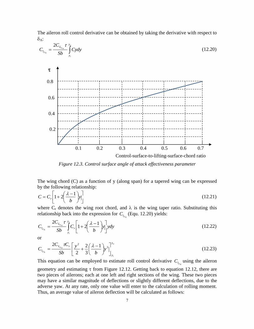
where a is the aileron effectiveness parameter and is obtained from Figure 12.12, given
the ratio between aileron-chord and wing-chord. Figure 12.12 is a general representative
of the control surface effectiveness; it may be applied to aileron (a), elevator (e), and
rudder (r). Thus, in Figure 12.12, the subscript of parameter is dropped to indicate the
generality.
Integrating over the region containing the aileron yields
o
i
w
y
y
AL
l CydySb
CC
2 (12.19)
where w
LC
has been corrected for three-dimensional flow and the factor 2 is added to
account for the two ailerons. For the calculation in this technique, the wing sectional lift
curve slope is assumed to be constant over the wing span. Therefore, the aileron sectional
lift curve slope is equaled to the wing sectional lift curve slope. The parameter yi
represents the inboard position of aileron with respect to the fuselage centerline, and yo
the outboard position of aileron with respect to the fuselage centerline (See Figure 12.11).
7
The aileron roll control derivative can be obtained by taking the derivative with respect to
A:
o
i
w
A
y
y
L
l CydySb
CC
2 (12.20)
Figure 12.3. Control surface angle of attack effectiveness parameter
The wing chord (C) as a function of y (along span) for a tapered wing can be expressed
by the following relationship:
y
bCC r
121
(12.21)
where Cr denotes the wing root chord, and is the wing taper ratio. Substituting this
relationship back into the expression for A
lC
(Equ. 12.20) yields:
o
i
w
A
y
y
r
L
l ydyyb
CSb
CC
121
2
(12.22)
or o
i
w
A
y
y
rL
l yb
y
Sb
CCC
3
2 1
3
2
2
2
(12.23)
This equation can be employed to estimate roll control derivative A
lC
using the aileron
geometry and estimating from Figure 12.12. Getting back to equation 12.12, there are
two pieces of ailerons; each at one left and right sections of the wing. These two pieces
may have a similar magnitude of deflections or slightly different deflections, due to the
adverse yaw. At any rate, only one value will enter to the calculation of rolling moment.
Thus, an average value of aileron deflection will be calculated as follows:
Control-surface-to-lifting-surface-chord ratio
0.1 0.2 0.3 0.4 0.5 0.6 0.7
0.8
0.4
0.6
0.2

8
rightleft AAA
2
1 (12.24)
The sign of this A will later be determined based on the convention introduced earlier; a
positive A will generate a positive rolling moment. Substituting equation 12.9 into
equation 12.7 yields:
PIyDL xxDA (12.25)
As the name implies,
P is the time rate of change of roll rate:
Pdt
dP
(12.26)
On the other hand, the angular velocity about x-axis (P) is defined as the time rate of
change of bank angle:
dt
dP (12.27)
Combining equations 12.26 and 12.27 and removing dt from both sides, results in:
PdPdP
(12.28)
Assuming that the aircraft is initially at a level cruising flight (i.e. Po = 0, o = 0), both
sides may be integrated as:
ssP
PdPdP00
(12.29)
Thus, the bank angle due to a rolling motion is obtained as:
dP
P
P (12.30)
where
P is obtained from equation 12.25. Thus:
ssP
DA
xx dPyDL
PI
0
(12.31)
Both aerodynamic rolling moment and aircraft drag due to rolling motion are functions of
roll rate. Plugging these two moments into equation 12.31 yields:
ss
R
P
DDvthtwDl
xx dP
yCSSSyPbSCq
PI
02
1
2
1
(12.32)
The aircraft rate of roll rate response to the aileron deflection has two distinct states: 1. A
transient state, 2. A steady state (See Figure 12.13). The integral limit for the roll rate (P)
in equation 12.32 is from an initial trim point of no roll rate (i.e. wing level and Po = 0) to
a steady-state value of roll rate (Pss). Since the aileron is featured as a rate control, the
deflection of aileron will eventually result in a steady-state roll rate (Figure 12.13). Thus,
unless the ailerons are returned to the initial zero deflection, the aircraft will not stop at a
specific bank angle. Table 12.12 defines the roll rate requirements in terms of the desired
9
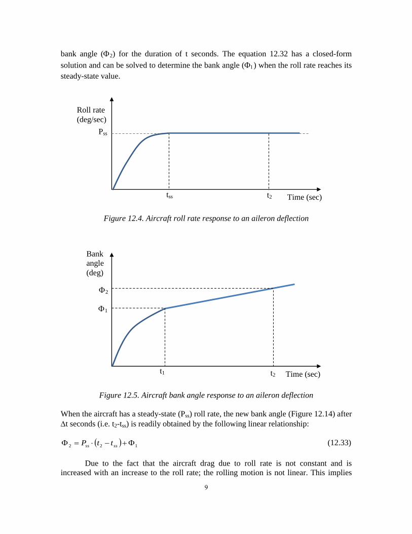
bank angle (2) for the duration of t seconds. The equation 12.32 has a closed-form
solution and can be solved to determine the bank angle () when the roll rate reaches its
steady-state value.
Figure 12.4. Aircraft roll rate response to an aileron deflection
Figure 12.5. Aircraft bank angle response to an aileron deflection
When the aircraft has a steady-state (Pss) roll rate, the new bank angle (Figure 12.14) after
t seconds (i.e. t2-tss) is readily obtained by the following linear relationship:
122 ssss ttP (12.33)
Due to the fact that the aircraft drag due to roll rate is not constant and is
increased with an increase to the roll rate; the rolling motion is not linear. This implies
t2
2
tss t2
t1
Roll rate
(deg/sec)
Time (sec)
Pss
Bank
angle
(deg)
Time (sec)
1

11
that the variation of the roll rate is not linear; and there is an angular rotation about x-
axis. However, until the resisting moment against the rolling motion is equal to the
aileron generated aerodynamic rolling moment; the aircraft will experience an angular
acceleration about x-axis. Soon after the two rolling moments are equal, the aircraft will
continue to roll with a constant roll rate (Pss). The steady-state value for roll rate (Pss) is
obtained by considering that the fact that when the aircraft is rolling with a constant roll
rate, the aileron generated aerodynamic rolling moment is equal to the moment of aircraft
drag in the rolling motion.
DRA yDL (12.34)
Combining equations 12.14, 12.15, and 12.16, the aircraft drag due to the rolling motion
is obtained as:
RDvthtwDR CSSSyPD
2
2
1 (12.35)
Inserting the equation 12.35 into equation 12.34 yields:
DDvthtwDA yCSSSyPLR
2
2
1 (12.36)
Solving for the steady-state roll rate (Pss) results in:
3
2
DDvthtw
Ass
yCSSS
LP
R
(12.37)
On the other hand, the equation 12.32 is simply a definite mathematical integration. This
integration may be modeled as the following general integration problem:
22 ax
xdxky (12.38)
According to [20], there is a closed form solution to such integration as follows:
22ln2
1axky (12.39)
The parameters k and a are obtained by comparing equation 12.38 with equation 12.32.
RDvthtwD
xx
CSSSy
Ik
3
2
(12.40)
3
2
2
DDvthtw
l
yCSSS
bSCVa
R
(12.41)
Hence, the solution to the integration in equation 12.32 is determined as:

11
ss
RR
P
DDvthtw
l
DvthtwD
xx
yCSSS
bSCVP
CSSSy
I
0
3
2
2
31 ln
(12.42)
Applying the limits (from 0 to Pss) to the solution results in:
2
31 ln ss
DvthtwD
xx PCSSSy
I
R
(12.43)
Recall that we are looking to determine aileron roll control power. In another word, it is
desired to obtain how long it takes (t2) to bank to a desired bank angle when ailerons are
deflected. This duration tends to have two parts: 1. The duration (tss) that takes an aircraft
to reach the steady-state roll rate (Pss), 2. The time (tR) to roll linearly from ss to 2
(See Figure 12.14).
Rss ttt 2 (12.44)
where
ss
RP
t 12 (12.45)
Comparing Figures 12.13 and 12.14 indicates that t1 = tss. The time (tss) that takes an
aircraft to achieve a steady-state roll rate due to an aileron deflection is a function of
angular acceleration (
P ). Based on classical dynamics, this accelerated roll can be
expressed as:
2
12
1sso tP
(12.46)
It is assumed that the aircraft is initially at a wing-level flight condition (i.e. o = 0).
Hence:
P
tt ss1
1
2 (12.47)
where 1 is determined from equation 12.43. In addition, in an accelerated rolling
motion, the relationship between final roll rate (P1) and initial roll rate (Po) is a function
of the rate of roll rate (
P ) and the final bank angle (1). Based on classical dynamics, an
accelerated rolling motion can be expressed as:
1
22
1 2
PPP o (12.48)
It is assumed that the aircraft is initially at a wing-level flight condition (i.e. Po = 0) and
the new roll rate is the steady-state roll rate (i.e. P1 = Pss). Thus:
1
2
2
ssP
P (12.49)
where Pss is determined from equation 12.45.

12
Figure 12.6. Bank angle versus time
For a GA and transport aircraft, the time to reach the steady state rolling motion
(t1) is long (more than ten seconds). Thus, the application of equations 12.48 and 12.49 is
often not needed for aileron design, since the roll requirement is within a few seconds.
However, for a fighter aircraft and missile, the rolling motion (See Figure 12.15) is very
fast (the time t1 is within a few seconds), so the application of equations 12.48 and 12.49
is usually needed for aileron design. For this reason, when the bank angle (1)
corresponding to steady state roll rate (Pss) is beyond 90 degrees, the equation 12.46
serves as the relationship between the required time to reach a desired bank angle.
Therefore, the duration required (treq) to achieve a desired bank angle (des) will be
determined as follows:
P
t des22
(12.50)
The equations and relationships introduced and developed in this section provide
the necessary tools to design the aileron to satisfy the roll control requirements. Table
12.12 addresses the military aircraft roll control requirements; for a civil aircraft, it is
suggested to adopt a similar list of requirements. To have the greatest roll control by
aileron to produce a rolling moment, consider the aileron outboard of the wing toward
wing tip. Therefore flap will be considered at the inboard of the wing. This approach will
result in the smallest, lightest and most economical aileron surfaces. The aileron design
technique and the design procedure will be presented in Section 12.4.4.
12.4.3. Aileron Design Constraints
Any design problem in the engineering discipline is usually limited by various constraints
and the aileron design is no exception. In this section, a number of constraints on the
aileron design will be introduced.
treq
Bank angle
(deg)
Time (sec)
req

13
12.4.3.1. Aileron Reversal
A number of aircraft when flying near their maximum speed are subject to an important
aero-elastic phenomenon. No real structure is ideally rigid; and it has static and dynamic
flexibility. Wings are usually produced from aerospace materials such as aluminum and
composite materials and have structures which are flexible. This flexibility causes the
wing not to be able to maintain its geometry and integrity especially in high speed flight
operations. This phenomenon which is referred to as aileron reversal negatively
influences the aileron effectiveness.
Consider the right-section of a flexible wing with a downward deflected aileron to
create a negative rolling moment. At subsonic speeds, the increment aerodynamic load
due to aileron deflection has a centroid somewhere near the middle of the wing chord. At
supersonic speeds, the control load acts mainly on the deflected aileron itself, and hence
has its centroid even farther to the rear. If this load centroid is behind the elastic axis of
the wing structure, then a nose-down twist (twist) of the main wing surface (about y axis)
results. The purpose of this deflection was to raise the right-wing section. However, the
wing twist reduces the wing angle of attack, and consequently a reduction of the lift on
the right-section of the wing (Figure 12.16). In extreme cases, the down-lift due to aero-
elastic twist will exceed the commanded up-lift, so the net effect is reversed. This change
in the lift direction will consequently generate a positive rolling moment.
This undesired rolling moment implies that the aileron has lost its effectiveness
and the roll control derivative; A
lC
has changed its sign. Such phenomenon is referred to
as aileron reversal. This phenomenon poses a significant constraint on aileron design. In
addition, structural design of the wing must examine this aeroelasticity effect of aileron
deflection. The aileron reversal often occurs at high speeds. Most high performance
aircraft have an aileron reversal speed beyond which the ailerons lose their effectiveness.
The F-14 fighter aircraft experiences aileron reversal at high speed.
a. An ideal and desired aileron b. An aileron with aileron reversal
Figure 12.7. Aileron reversal
A
A
twist

14
Clearly, such aileron reversal is not acceptable within the flight envelope, and
must be considered during design process. A number of solutions for such problem are: 1.
Making the wing stiffer, 2. Limit the range of aileron deflections at high speed, 3.
Employing two sets of ailerons; one set at inboard wing section for high speed flight, and
one set at outboard wing section for high speed flight, 4. Reduce the aileron chord, and 5.
Using spoiler for roll control, 6. Moving the ailerons toward wing inboard section. The
transport aircraft Boeing 747 has three different types of roll control device: inboard
ailerons, outboard ailerons, and spoilers. The outboard ailerons are disabled except in
low-speed flights when the flaps are also deflected. Spoilers are essentially flat plates of
about 10-15% chord located just ahead of the flaps. When spoilers are raised, they cause
a flow separation and local loss of lift. Thus, to avoid roll reversal within the operational
flight envelope, the wing structure must be designed with sufficient stiffness.
12.4.3.2. Adverse Yaw
When an airplane is banked to execute a turn, it is desired that aircraft yaws and rolls
simultaneously. Furthermore, it is beneficial to have the yawing and rolling moments in
the same direction (i.e. both either positive or negative). For instance, when an aircraft is
to turn to the right, it should be rolled (about x-axis) clockwise and yawed (about z-axis)
clockwise. In such a turn, the pilot will have a happy and comfortable feeling. Such
yawing moment is referred to as pro-verse yaw, and such turn is a prerequisite for a
coordinated turn. This yaw keeps the aircraft pointing into the relative wind. On the other
hand, if the aircraft yaws in a direction opposite to the desired turn direction (i.e. a
positive roll, but a negative yaw); pilot will not have a desirable feeling and aircraft turn
is not coordinated. This yawing moment is referred to as adverse yaw. When a turn is not
coordinated, the aircraft will either slip or skid.
To see why and how these turns may happen, see Figure 12.17 where the pilot is
planning to turn to the right. For such a goal, the pilot must apply a positive aileron
deflection (i.e. left-aileron down and right-aileron up). The lift distribution over the wing
in a cruising flight is symmetric; i.e. the right-wing-section lift and the left-wing-section
lift are the same. When the left aileron is deflected down and right aileron is deflected up,
the lift distribution varies such that the right-wing-section lift is more than left-wing-
section lift. Such deflections create a clockwise rolling moment (Fig. 12.17a) as desired.
However, the aileron deflection simultaneously alters the induced drag of right
and left wing differently. Recall that wing drag components of two parts: zero-lift drag
(Do) and induced drag (Di). The wing induced drag is a function of wing lift coefficient (2
LD CKCi
). Since the right-wing-section local lift coefficient is higher than the left-
wing-section local lift coefficient, the right-wing-section drag is higher than the left-
wing-section drag. The drag is an aerodynamic force and has an arm relative to the

15
aircraft center of gravity. The drag direction is rearward, so this wing-drag-couple is
generating a negative (See Fig. 12.17b) yawing moment (i.e. adverse yaw). Thus, if the
rudder is not deflected simultaneously with aileron deflection, the direction of the
aileron-generated rolling moment and the wing-drag generated yawing moment would
not be coordinated. Thus, when a pilot deflects a conventional aileron to make a turn, the
aircraft will initially yaw in a direction opposite to that expected.
a. Front view (positive roll)
b. Down-view (negative yaw)
Figure 12.8. Adverse yaw due to wing drag
The phenomenon of adverse yaw imposes a constraint on the aileron design. To
avoid such an undesirable yawing motion (i.e., adverse yaw), there are a number of
solutions; four of which are as follows: 1. Employ a simultaneous aileron-rudder
deflections such that to eliminate the adverse yaw. This requires an interconnection
between aileron and rudder. 2. Differential ailerons; i.e. up-deflection of the aileron in
one side is greater than the down-deflection of the other aileron. This causes equal
induced drag in right and left wing during a turn. 3. Employ Frise aileron in which the
aileron hinge line is higher than the regular location. 4. Employ spoiler. Both Frise
aileron and spoiler are creating a wing drag such the both wing-sections drags are
balanced. Most Cessna aircraft use Frise ailerons, but most Piper aircraft employ
differentially deflected ailerons. The critical condition for an adverse yaw occurs when
the airplane is flying at slow speeds (i.e. high lift coefficient). This phenomenon means
cg
+A
Lleft +A
Lright
Dleft Dright
V∞

16
that designer must consider the application of one or combination of the above-mentioned
techniques to eliminate adverse yaw.
12.4.3.3. Flap
The wing trailing edge in a conventional aircraft is the home for two control surfaces; one
primary (i.e. aileron), and one secondary (i.e. trailing edge high lift device such as flap).
As the aileron and the flap are next to each other along the wing trailing edge, they
impose a span limit on one another (Fig. 12.16). The balance between aileron span (ba)
and flap span (bf) is a function of the priority of roll control over the take-off/landing
performance. To improve the roll control power, the ailerons are to be placed on the
outboard and the flap on the inboard part of the wing sections. The application of high lift
device applies another constraint on the aileron design which must be dealt with in the
aircraft design process.
The spanwise extent of aileron depends on the amount of span required for
trailing edge high lift devices. In general, the outer limit of the flap is at the spanwise
station where the aileron begins. The exact span needed for ailerons primarily depend of
the roll control requirements. A low speed aircraft usually utilizes about 40% of the total
wing semispan for ailerons. This means that flaps can start at the side of the fuselage and
extend to the 60% semispan station. However, with the application of spoilers, the
ailerons are generally reduced in size, and the flaps may extend to about 75% of the wing
semispan. Furthermore, if a small inboard aileron is provided for gentle maneuvers, the
effective span of the flaps is reduced.
If the take-off/landing performance is of higher importance in the priority list, try
to devote a small span to aileron; so that a large span can be occupied by powerful flaps.
This in turn means lower stall speed and more safety. On the other hand, if roll control
has higher priority than the take-off/landing performance, the ailerons should be designed
before the flaps are designed. Due to of the importance of the roll control in a fighter
aircraft, span of the flaps must be selected as short as possible, so that the span of the
aileron is long enough. Therefore, in a fighter aircraft, it is advised to design the aileron
prior to flap design. On the other hand, in the case of civil GA and transport aircraft, it is
recommended to design flap first, while in the case of a fighter aircraft, design aileron
first.
12.4.3.4. Wing Rear Spar
Another aileron design constraint in a conventional aircraft is applied by the wing rear
spar. Aileron needs a hinge line to rotate about and to provide the aileron with a sufficient
freedom to operate. To have lighter and a less complicated wing structure, it is advised to
consider the wing rear spar as the most forward limit for the aileron. This may limit the
aileron chord; but at the same time, improves the wing structural integrity. In addition, it

17
is structurally better to have the same chord for aileron and flaps. This selection results in
a lighter structure and allows the rear spar to hold both flap and aileron. Therefore the
aileron-to-wing attachment through the rear spar (See Fig. 12.18) is considered as both a
constraint, and at the same time, an attachment point.
Section A-A Top-view of the wing
Figure 12.9. Flap, aileron and rear spar
12.4.3.5. Aileron Stall
When ailerons are deflected more than about 20-25 degrees, flow separation tends to
occur. Thus, the ailerons will lose their effectiveness. Furthermore, close to wing stall,
even a small downward aileron deflection can produce flow separation and loss of roll
control effectiveness. To prevent roll control effectiveness, it is recommended to consider
the aileron maximum deflection to be less than 25 degrees (both up and down). Hence,
the maximum aileron deflection is dictated by the aileron stall requirement. Table 12.19
provides a technique to determine the stall angle of a lifting surface (e.g. wing) when its
control surface (e.g. aileron) is deflected.
12.4.3.6. Wingtip
Due to a spanwise component of airflow along the wing span, there is a tendency for the
flow to leak around the wing tips. This flow establishes a circulatory motion that trails
downstream of the wing. Thus, a trailing vortex is created at each wing tip. To consider
effects of vortex flow at the tip of the wing, span of the ailerons must not run toward
wingtip. In another word, some distance must exist between outer edge of the aileron and
tip of the wing (See Fig 12.16).
A
bf/2
Flap Aileron
Wing
Tip
Wing trailing edge
Main Spar
Rear Spar
A
bai/2

18
12.4.4. Steps of Aileron Design
In Sections 12.4.1 through 12.4.3, aileron function, design criteria, parameters, governing
rules and equations, formulation, design requirements have been developed and
presented. In addition, Section 12.3 introduces the roll control and lateral handling
qualities requirements for various aircraft and flight phases. In this section, aileron design
procedures in terms of design steps are introduced. It must be noted that there is no
unique solution to satisfy the customer requirements in designing an aileron. Several
aileron designs may satisfy the roll control requirements, but each will have a unique
advantages and disadvantages. Based on the systems engineering approach, the aileron
detail design begins with identifying and defining design requirements and ends with
optimization. The following is the aileron design steps for a conventional aircraft:
1. Layout design requirements (e.g. cost, control, structure, manufacturability, and
operational)
2. Select roll control surface configuration
3. Specify maneuverability and roll control requirements
4. Identify the aircraft class and critical flight phase for roll control
5. Identify the handling qualities design requirements (Section 12.3) from resources
such as aviation standards (e.g. Table 12.12). The design requirements primarily
include the time (treq) that takes an aircraft to roll from an initial bank angle to a
specified bank angle. The total desired bank angle is denoted as des.
6. Specify/Select the inboard and outboard positions of the aileron as a function of wing
span (i.e. bai/b and bao/b). If the flaps are already designed, identify the outboard
position of the flap; then consider the inboard location of the aileron to be next to the
outboard position of the flap.
7. Specify/Select the ratio between aileron-chord to the wing-chord (i.e. Ca/C). An
initial selection for the aileron leading edge may be considered as the next to the wing
rear spar.
8. Determine aileron effectiveness parameter (a) from Figure 12.12.
9. Calculate aileron rolling moment coefficient derivative (A
lC
). You may use
references such as [19] or estimate the derivative by employing equation 12.23.
10. Select the maximum aileron deflection (Amax). A typical value is about ±25 degrees.
11. Calculate aircraft rolling moment coefficient (Cl) when aileron is deflected with the
maximum deflection (equation 12.13). Both positive and negative deflections will
serve the same.
12. Calculate aircraft rolling moment (LA) when aileron is deflected with the maximum
deflection (equation 12.10)
13. Determine the steady-state roll rate (Pss) employing equation 12.37.
14. Calculate the bank angle (1) at which the aircraft achieves the steady state roll rate
(equation 12.43)

19
15. Calculate the aircraft rate of roll rate (
P ) that is produced by the aileron rolling
moment until the aircraft reaches the steady-state roll rate (Pss) by using equation
12.49.
16. If the bank angle (1) calculated in step 14 is greater than the bank angle (req) of
step 5, determine the time (t) that takes the aircraft to achieve the desired bank angle
using equation 12.50. The desired bank angle is determined in step 5.
17. If the bank angle (1) calculated in step 14 is less than the bank angle (req) of step 5,
determine the time (t2) that takes the aircraft to reach the desired bank angle (2 or
req) using equations 12.44 and 12.45.
18. Compare the roll time obtained in step 16 or 17 with the required roll time (treq)
expressed in step 5. In order for the aileron design to be acceptable, the roll time
obtained in step 16 or 17 must be equal or slightly longer than the roll time specified
in step 5.
19. If the duration obtained in step 16 or 17 is equal longer than the duration (treq) stated
in step 5, the aileron design requirement has been met and move to step 26.
20. If the duration obtained in step 16 or 17 is shorter than the duration (treq) stated in step
5, the aileron design has not met the requirement. The solution is; either to increase
the aileron size (aileron span or chord); or to increase the aileron maximum
deflection.
21. If the aileron geometry is changed, return to step 7. If the aileron maximum deflection
is changed, return to step 10.
22. In case where an increase in the geometry of aileron does not resolve the problem; the
entire wing must be redesigned; or the aircraft configuration must be changed.
23. Check aileron stall when deflected with its maximum deflection angle. If aileron stall
occurs, the deflection must be reduced.
24. Check the features of adverse yaw. Select a solution to prevent it.
25. Check the aileron reversal at high speed. If it occurs; either redesign the aileron, or
reinforce the wing structure.
26. Aerodynamic balance/mass balance if necessary (Section 12.7)
27. Optimize the aileron design
28. Calculate aileron span, chord, area, and draw the final design for the aileron
12.8.1. Aileron Design Example
Example 12.4
Problem statement: Design the roll control surface(s) for a land-based military transport
aircraft to meet roll control MIL-STD requirements. The aircraft has a conventional
configuration and the following geometry and weight characteristics:
mTO = 6,500 kg, S = 21 m2, AR = 8, = 0.7, Sh = 5.3 m
2, Sv = 4.2 m
2, Vs = 80 knot, CLw
= 4.5 1/rad, Ixx = 28,000 kg.m2

21
Furthermore, the control surface must be of low cost and manufacturable. The high lift
device has been already designed and the outboard flap location is determined to be at
60% of the wing semispan. The wing rear spar is located at 75% of the wing chord.
Solution:
Step 1:
The problem statement specified the maneuverability and roll control requirements to
comply with military standards.
Step 2:
Due to the aircraft configuration, simplicity of design, and a desire for a low cost, a
conventional roll control surface configuration (i.e. aileron) is selected.
Step 3:
Hence, Table 12.12 will be the reference for the aileron design which expresses the
requirement as the time to achieve a specified bank angle change.
Step 4:
Based on Table 12.5, a land-based military transport aircraft with a mass of 6,500 kg
belongs to Class II. The critical flight phase for a roll control is at the lowest speed. Thus,
it is required that the aircraft must be roll controllable at approach flight condition.
According to Table 12.6, the approach flight operation is considered as a phase C. To
design the aileron, level of acceptability of 1 is considered. Therefore:
Class Flight phase Level of acceptability
II C 1
Step 5:
The roll control handling qualities design requirement is identified from Table 12.12-b
which states that the aircraft in Class II, flight phase C for a level of acceptability of 1 is
required to be able to achieve a bank angle of 30o in 1.8 seconds.
Step 6:
According to the problem statement, the outboard flap location is at 60% of the wing
span. So the inboard and outboard positions of the aileron as a function of wing span (i.e.
bai/b and bao/b) are tentatively selected to be at 70% and 95% of the wing span
respectively.
Step 7:
The wing rear spar is located at 75% of the wing chord, so the ratio between aileron-
chord to the wing-chord (i.e. Ca/C) is tentatively selected to be 20%.
Step 8:

21
The aileron effectiveness parameter (a) is determined from Figure 12.12. Since the
aileron-to-wing chord ratio is 0.2, so the aileron effectiveness parameter will be 0.41.
Step 9:
The aileron rolling moment coefficient derivative (A
lC
) is calculated employing equation
12.22.
o
i
w
A
y
y
rL
l yb
y
Sb
CCC
3
2 1
3
2
2
2
(12.23)
We first need to determine wing span, wing mean aerodynamic chord, and wing root
chord.
mbARSbS
bAR 49.141021
2
(5.19)
mCAR
bC
C
bAR 449.1
10
49.14 (5.18)
mCCCC rrr 604.18.01
8.08.01
3
2449.1
1
1
3
2 22
(5.26)
The inboard and outboard positions of the aileron as a function of wing span are selected
to be at 70% and 90% of the wing span respectively. Therefore:
mb
yi 072.52
49.147.0
27.0
mb
yo 883.62
49.1495.0
295.0
Plugging the values for the parameters in equation 12.23 is as follows:
3
23
2
072.549.14
18.0
3
2
2
072.5883.6
49.14
18.0
3
2
2
883.6
49.1421
604.141.05.42A
lC
which yields:
radC
Al
1176.0
Step 10:
A maximum aileron deflection (Amax) of ±20 degrees is selected.
Step 11:
The aircraft rolling moment coefficient (Cl) when aileron is deflected with the maximum
deflection is:

22
061.03.57
20176.0 All
A
CC
(12.13)
Step 12:
The aircraft rolling moment (LA) when aileron is deflected with the maximum deflection
is calculated. The typical approach velocity is 1.1 to 1.3 times the stall speed, thus the
aircraft is considered to approach with a speed of 1.3 Vs. In addition, the sea level altitude
is considered for the approach flight operation.
s
mknotVV sapp 5.53104803.13.1
NmbSCVL lappA 6.692,3249.14061.0215.53225.12
1
2
1 22 (12.11)
Step 13:
The steady-state roll rate (Pss) is determined.
3
2
DDvthtw
Ass
yCSSS
LP
R
(12.37)
An average value of 0.9 is selected for wing-horizontal tail-vertical tail rolling drag
coefficient is selected. The drag moment arm is assumed to at 405 of the wing span, so:
s
mbyD 898.2
2
49.144.0
24.0
sec937.8
898.29.02.43.521225.1
6.692,323
radPss
(12.37)
Step 14:
Calculate the bank angle (1) at which the aircraft achieves the steady state roll rate:
2
3
2
31 937.8ln9.02.43.521898.2225.1
000,28ln
ss
DvthtwD
xx PCSSSy
I
R
(12.43)
deg14.858482.1491 rad
Step 15:
Calculate the aircraft rate of roll rate (
P ) that is produced by the aileron rolling moment
until the aircraft reaches the steady-state roll rate (Pss).
2
2
1
2
sec267.0
82.1492
937.8
2
radPP ss
(12.49)
Step 16 and 17:
The bank angle (1) calculated in step 14 is compared with the bank angle (req) of step
5. Since the bank angle calculated in step 14 (i.e. 8,584 degrees) is shorter than the bank

23
angle (req) of step 5 (i.e. 30 degrees), the time that takes the aircraft to achieve the bank
angle of 30 degrees is determined.
sec982.1267.0
30222
P
t des (12.47)
Step 18:
The roll time obtained in step 16 or 17 is compared with the required roll time (treq)
expressed in step 5. The roll time obtained in step 16 or 17 to achieve the bank angle of
30 degrees (i.e. 1.982 sec) is longer than the roll time expressed in step 5 (i.e. 1.8 sec).
Hence the current aileron design does not satisfy the requirements and must be
redesigned.
Step 19 and 20:
The duration obtained in step 16 or 17 is shorter than the duration (treq) stated in step 5, so
the aileron design has not met the requirement. The solution is; either to increase the
aileron size (aileron span or chord); or to increase the aileron maximum deflection. Due
to the aileron stall concern, and the location of rear spar, the maximum aileron deflection
and the aileron-chord-to-wing-chord ratio are not altered. The flap outboard location is
located at 60% of the wing span, thus the safest solution is to increase the aileron span.
Step 21:
By trial and error, it is determined that the aileron inboard span at 61% of the wing span
will satisfy the roll control requirements. The calculation is as follows:
mb
yi 42.42
49.1461.0
261.0
mb
yo 883.62
49.1495.0
295.0
3
23
2
42.449.14
18.0
3
2
2
42.4883.6
49.14
18.0
3
2
2
883.6
49.1421
604.141.05.42A
lC
radC
Al
1228.0
08.03.57
20228.0 All
A
CC
(12.13)
NmbSCVL lappA 6.429,4249.1408.0215.53225.12
1
2
1 22 (12.11)
3
2
DDvthtw
Ass
yCSSS
LP
R
(12.37)

24
sec181.10
898.29.02.43.521225.1
6.429,423
radPss
(12.37)
Figure 12.10. Variations of bank angle versus time for aircraft in Example 12.4
2
3
2
31 181.10ln9.02.43.521898.2225.1
000,28ln
ss
DvthtwD
xx PCSSSy
I
R
deg909574.1581 rad
2
2
1
2
sec327.0
74.1582
181.10
2
radPP ss
(12.49)
sec791.1327.0
30222
P
t des (12.50)
The variations of bank angle versus time are plotted in Figure 12.44.
Steps 26: Aerodynamic balance/mass balance (out of scope of this example)
Steps 27: Optimization (out of scope of this example)
Steps 28: Geometry
The geometry of each aileron is as follows:
myyb iAoAA 464.242.4883.6
cmCC wA 29.0449.12.02.0
0 0.5 1 1.5 2 2.50
5
10
15
20
25
30
35
40
time (sec)
(
deg)
1.791 sec

25
Section A-A
Top-view of the right wing section
Figure 12.11. Wing and aileron of Example 12.4
The overall planform area of both left and right ailerons is:
2428.129.0464.222 mCbA AAA (12.43)
The top and side views of the right wing section including the aileron are shown in Figure
12.45. It must be noted that the aileron chord was assumed to be 20% of the wing chord
throughout the aileron span. However, the wing is tapered, so in fact, the aileron needs to
be tapered too. To make the application and the fabrication of the aileron easier, a
constant chord aileron is selected; hence, a change in the aileron chord must be applied in
the later design stage to correct for the assumption.
20 deg
20 deg
0.29 m
2.464 m
A
0.6 b/2
Flap Aileron
Rear Spar
A