AIAA 2003–3698 - Aerospace Computing Lab -...
18
AIAA 2003–3698 Aircraft Gas Turbine Engine Simulations W. C. Reynolds , J. J. Alonso, and M. Fatica Center for Integrated Turbulence Simulations Stanford University, Stanford, CA 94305 16th AIAA Computational Fluid Dynamics Conference June 23–26, 2003/Orlando, FL For permission to copy or republish, contact the American Institute of Aeronautics and Astronautics 1801 Alexander Bell Drive, Suite 500, Reston, VA 20191–4344
Transcript of AIAA 2003–3698 - Aerospace Computing Lab -...

AIAA 2003–3698Aircraft Gas Turbine EngineSimulationsW. C. Reynolds , J. J. Alonso, and M. Fatica
Center for Integrated Turbulence SimulationsStanford University, Stanford, CA 94305
16th AIAA Computational Fluid Dynamics ConferenceJune 23–26, 2003/Orlando, FL
For permission to copy or republish, contact the American Institute of Aeronautics and Astronautics1801 Alexander Bell Drive, Suite 500, Reston, VA 20191–4344

AIAA 2003–3698
Aircraft Gas Turbine Engine Simulations
W. C. Reynolds∗, J. J. Alonso†, and M. Fatica‡
Center for Integrated Turbulence SimulationsStanford University, Stanford, CA 94305
The Center for Integrated Turbulence Simulations (CITS) was created in October of1997 under the sponsorship of the Department of Energy (DoE) Accelerated StrategicComputing Initiative (ASCI) Alliance program. The over-arching problem to be solvedby this Center is the detailed, high-fidelity simulation of the flowpath through completeaircraft gas turbines including the compressor, combustor, turbine, and secondary flowsystems. In order to support this goal, three groups were created to tackle the maincomponents of the program. The turbomachinery group has developed a multiblock-structured, unsteady Reynolds-Averaged Navier-Stokes (URANS) solver called TFLOwhich is used for the rotating components of the flowpath (compressor and turbine) andfor the secondary flow system. The combustion group is responsible for the flow in thecombustor and compressor diffuser. Given the complexity of the flow in this region ofthe engine, an unstructured Large Eddy Simulation (LES) solver called CDP has beendeveloped and validated together with various approaches for combustion simulation andspray tracking. A significant portion of the work in the Center is the integration betweenthe various physics and components being modeled. For this purpose, an integrationgroup is working towards the development of interface definitions for arbitrary URANSand LES solvers. An important aspect of the problems to be solved is that they are ofsuch magnitude and complexity that they require the largest available supercomputers.For this reason, a major thrust of the Center is on the parallel implementation of thesolver software and its integration on massively parallel computing platforms. This paperpresents some of the major results from each of the three groups in the Center.
Introduction
THE goal of the DoE’s ASCI Alliance program is topush the development of comprehensive numeri-
cal simulation tools for important engineering prob-lems of interest to the DoE Defense Programs. Thework at the five Alliance universities is associatedwith physical modeling and software development fora particular unclassified application chosen by thatuniversity. The Stanford application is the flow andcombustion in aircraft gas turbine engines.
Fig. 1 shows the Pratt & Whitney 6000 engine, anadvanced modern engine that provides the focus forour simulations. The large axial flow fan at the frontof the engine will be familiar to anyone who has flowna modern commercial jet aircraft. It moves most of theair that provides the engine thrust. The fan is drivenby a gas turbine engine, consisting of a two-stage com-pressor that raises the air pressure, a combustor thatheats the air, and a two-stage turbine that extracts me-chanical energy from the air. The first high-pressurehigh-speed turbine drives the compressor, and the sub-sequent low-pressure low-speed turbine drives the fan.The flow exiting the turbine at relatively high velocity
∗Professor Emeritus, AIAA Associate Fellow†Assistant Professor, AIAA Member‡Senior Research EngineerCopyright c© 2003 by the authors. Published by the American
Institute of Aeronautics and Astronautics, Inc. with permission.
provides additional thrust to augment that producedby the fan. In a modern engine like this, a significantfraction of the compressor flow bypasses the combus-tor and flows inside the high-pressure turbine blades tocool them, and then out through the blade surface toprovide a cool protective film that prevents melting ofthe blades by the very hot combustor exhaust. All ofthis presents a very challenging engineering problemfor which accurate simulations of the flow and com-bustion and their interactions with the structure arevery important. The primary goal of the simulationcomponent of the Stanford ASCI program is to makea major advance in this simulation technology.
Turbulence is important in all components of an air-craft engine. The Stanford ASCI program is closelycoupled to fundamental research in turbulence physics,modeling, and simulation being conducted in the Stan-ford/NASA Center for Turbulence Research (CTR).The coupled CTR/CITS efforts on turbulence simula-tion are the most substantial set of such activities inthe USA and are among the very best such activitiesworldwide. The group is pioneering major develop-ments in turbulent combustion physics and simulation,and is also contributing advanced turbulence modelsfor non-reacting turbulent flow analysis. This will beevident in the brief outline of the scope of the enginesimulations that follows and in the details presentedin the subsequent sections.
1 of 17
American Institute of Aeronautics and Astronautics Paper 2003–3698

Fig. 1 The PW6000 aircraft gas turbine engine.
Engine Component Simulation
The engine simulation involves two main efforts nowbeing integrated as we move forward to full enginesimulation. The turbomachinery is modeled using theunsteady Reynolds-Averaged Navier Stokes (RANS)equations that employ advanced turbulence models be-ing developed at Stanford as part of this and othersponsored research. The turbomachinery code TFLOis a derivative of unsteady flow codes previously de-veloped. The combustor is modeled using Large EddySimulation (LES), which has been developed with theconservation properties essential for LES.
TFLO has proven to be comparable in performanceand physical content with the best industrial turbo-machinery codes, and with coming improvements inalgorithms TFLO is expected to become superior tothe industrial codes over the next few years.
RANS combustor codes do not do a good job ofmodeling turbulent mixing in the very complex flowtypical of combustor chambers, and our LES code(here designated as CDP) has already proven to bemuch more accurate in this regard. The LES com-bustor code is rapidly taking combustor simulationtechnology to a very high new level. Others have writ-ten LES codes for combustion, but these codes lackthe conservative, non-dissipative property of our codesthat is essential for accurate turbulent flow prediction.Considerable interest in this code is now evident onthe part of the aircraft engine industry, particularlyPratt & Whitney, which is collaborating closely withour team on applications to their combustor geome-tries.
Engine Code Integration
The RANS turbomachinery and LES combustorcodes are being integrated to enable coupled simula-tion of the turbomachinery and combustor. As theavailable computer power increases, it should becomepossible to do a very detailed integrated simulation ofan entire aircraft engine. This capability would revo-lutionize the design and development processes and
associated cost for aircraft gas turbine engines andmany other systems.
The turbomachinery code TFLO was developedrapidly as a derivative of existing codes. However, thedevelopment of the unstructured mesh LES combus-tor code started from scratch with this program, andit has taken more time to bring it to the point whereit can be integrated with TFLO. In order to get someexperience with code integration, we have integratedTFLO with a RANS combustor code, the NationalCombustor Code (NCC) developed at NASA/GlennResearch Center. In collaboration with researchersfrom NASA/Glenn, we have developed an interfacethat can couple TFLO and the NCC. This frameworkis now used (almost unaltered) to integrate TFLO andCDP and therefore, valuable integration experiencewas gained with the all-RANS integrated simulations.
Turbomachinery SimulationsThe objective of the turbomachinery group is to
simulate complex unsteady flows in the rotating com-ponents of a jet engine both accurately and efficiently.The flows around the rotating blades of compressorsand turbines are characterized by a number of un-steady physical phenomena that require the solution ofthe time-dependent Reynolds-Averaged Navier-Stokesequations with a suitable turbulence model. Turbu-lent boundary layers and secondary flows, transition,flow separation, heat transfer, blade-wake and blade-shock interactions, and other effects, dictate the needfor nonlinear fluid dynamics and turbulence modelsthat can resolve fluctuations with disparate tempo-ral and spatial scales. For these reasons, the accuratecomputation of these unsteady flows requires long timeintegrations on very large meshes with substantial res-olution.
In order to simulate these flows, the turbomachinerygroup has developed a solver, TFLO, (Turbomachin-ery FLO solver), that is capable of achieving bothhigh single-processor performance and scalable par-allel efficiency using a FORTRAN 90/95, MPI-basedimplementation. A number of ingredients contributeto making TFLO a state-of-the-art solver. In order toreach a level of maturity that is now comparable withindustrial solvers, we have developed an efficient base-line algorithm that integrates an explicit, multigrid,Runge-Kutta solver for the mean flow with both ADI(Alternating Direction Implicit) and DDADI (Diago-nally Dominant ADI) solution methodologies for theturbulence model equations. Time integration is car-ried out using an implicit dual-time stepping scheme,and a sliding mesh interface with conservative inter-polation is used to treat the problem of relative blademotion.
Despite great improvements in the performance ofturbulence model implementations, parallel efficiencyand parallel I/O, and the dual-time stepping time-
2 of 17
American Institute of Aeronautics and Astronautics Paper 2003–3698

integration, and despite the fact that the efficiency ofTFLO can be considered to be state-of-the-art, typicalunsteady computations of the flow in complete com-pressors and turbines on current supercomputers stillrequire several months of runtime using large num-bers of processors. In order to be able to use toolssuch as TFLO not only for validation/verification butalso for new scientific discoveries and alternative en-gine component designs, the turnaround time of thesecalculations must be reduced by over an order of mag-nitude through algorithmic improvements alone. Theincreasing processor speeds, together with computerswith larger numbers of processors, will contribute theremaining factor needed to complete these calculationswith overnight turnaround.
For these reasons, a large portion of our work duringthe last year has focused on the study of a number ofalgorithmic alternatives that can improve the steady-state and unsteady performance of TFLO by an orderof magnitude. Our progress with four candidate algo-rithms has been reported previously and can be foundin the Center Technical Report.2 Only a brief descrip-tion of this work is presented here.
In addition, we have continued to improve the qual-ity of the predictions from TFLO by concentrating ona number of basic science issues which will also be dis-cussed in this paper briefly. Finally, the results of theuse of TFLO in some key large-scale simulations offlows in turbines are shown, together with the phys-ical insight gained from the post-processing of thesecalculations.
Large-Scale Turbomachinery Simulations
The process of developing the capability to performintegrated, multi-component simulations of major orwhole sections of a gas-turbine engine includes in-termediate steps. These steps consist of validation,verification, and demonstration of the ability to com-pute the flow through major sections or entire com-ponents of the engine, such as the complete high- orlow-pressure turbine or combustor. This section fo-cuses on one of the many such efforts that have beentackled by the turbomachinery group during the pastyear.
TFLO Validation - Transonic Turbine Rig
Validation of the TFLO code for multi-stage, un-steady flow has continued primarily for turbines. Dur-ing the past year, the validation of TFLO for asingle-stage, transonic, high-pressure turbine, transi-tion duct, and 1st-vane of the low-pressure turbineconfiguration was completed and the results are dis-cussed in this section. Details can be found in the workof Davis.3 Detailed comparisons between the predictedand experimental fundamental and 1st harmonics ofthe unsteady airfoil surface pressure spectrum wereperformed. One quarter of the rig circumference us-
ing 9-HPT-vanes, 14-HPT-blades, 9-LPT-vanes wasmodelled in the investigation. The configuration wasdiscretized with over 32 million grid points and theunsteady-flow solution was obtained with 192 proces-sors of the DoE Blue Pacific IBM SP2 at LawrenceLivermore National Laboratory. This investigationshowed that the TFLO code predicted the unsteadysurface pressure non-dimensionalized by the upstreamtotal pressure to within 0.6 percent. Comparisons be-tween the TFLO results with the predictions from asimilar Pratt & Whitney in-house code showed excel-lent agreement.
Fig. 2 illustrates the various phenomena that lead tothe unsteady interactions between the three compo-nents, especially those between the blade, transitionduct, and low-pressure turbine vane. These figuresshow the instantaneous entropy and pressure contoursat the 10% span, mid-span, and 90% span planes. Thepressure contours shown in Fig. 2 illustrate the pres-sure jump associated with the blade trailing edge shocksystem. As the blade rotates, the blade trailing edgeshock extends to the downstream vane where it strikesand sweeps forward along the vane pressure side. Theblade tip radius is approximately 31.6 cm. The shocksheet generated from the blade trailing edge shock sys-tem propagates downstream at a constant radius sothat only radial positions below 31.6 cm are directlystruck by this shock. The peak unsteady pressure onthe vane pressure side is located near the leading edgeand around 31.6 cm for this reason. Some moder-ate levels of unsteady pressure are also located on thevane near and above mid-span. The source of this un-steady pressure is believed to be from blade trailingedge shock reflections off of the transition duct intothe vane. Another area of high unsteady pressure isat the vane tip leading edge near the 90% span loca-tion. The unsteady pressures at this location can beattributed to the blade tip vortex that migrates in-board somewhat as it convects through the transitionduct.
As shown in Fig. 2, the wakes at mid-span fromthe upstream first vane mix with the blade wakes intobands of high entropy that are clocked to the lead-ing edge of the downstream low-pressure turbine vane.Several recent investigations into blade wake clock-ing in multi-stage turbomachinery suggest that thecurrent vane wake clocking could provide optimal per-formance. The blade wakes strike the downstreamvane at the leading edge and, along with the firstvane wakes, tend to migrate to the suction side of thelow-pressure turbine vane. At the 10% and 90% spanlocations, the secondary and tip vortex flows mix withthe first vane wakes more thoroughly such that the en-tropy going into the second vane is more uniform. Theblade tip vortex strikes the low-pressure turbine vaneleading edge and migrates to the pressure side of thevane. There are typically two blade/tip vortex wakes
3 of 17
American Institute of Aeronautics and Astronautics Paper 2003–3698

Blade Wakes
WakesVane/BladeMixed 1st
Wakes1st Vaneand Mix withSlice Through
}
}
}}
Mixed BladeWakes
Stacked 1stand 2nd VaneWakes
}
Blade WakesSlice Throughand Mix with1st VaneWakes
1st VaneWakes Mergewith 2nd Vane
Bands of 1stVane WakesClocked with2nd Vane
}
Blade and Tip
Pressure Sideto 2nd VaneWakes MigrateBlade and Tip
Vortex Wakes
10% Span Mid-Span 90% SpanEntropy Contours
Reflected Waves
Side Trailing−Edge ReflectedShock
Upstream−Traveling
Blade Suction−Side Trailing−
Blade Pressure−
Edge Shock
Blade Suction−
Traveling
Side Trailing−Edge Shock
Blade Pressure−Side Trailing−Edge ReflectedShock
Upstream−
Reflected Waves
Blade Suction−
Reflected WavesTravelingUpstream−
Edge ShockSide Trailing−
10% Span Mid-Span 90% SpanPressure Contours
Fig. 2 Computed Instantaneous Entropy and Pressure Contours at 10%, 50% and 90% Span for aTransonic HPT, Transition Duct, 1st-Vane LPT Rig Configuration
in the low-pressure turbine vane passage at any instantin time.
The unsteady pressure signals on the blade sur-faces were post-processed using Fast Fourier Trans-forms (FFT) to obtain information in the frequencydomain. Clark4 showed that the fundamental and firstharmonic of the pressure make up over 90% of the pres-sure envelope over most of the surface.
A comparison between the computed and experi-mental unsteady surface spectrum at points on theblade surface where the amplitude of the unsteadypressure was also performed. The computed pressurespectra are in good agreement with the experimentaldata. On the pressure side of the blade, the maximumdifferences between the computed and experimentalamplitudes of the fundamental and first harmonic arearound 0.1% of the inlet total pressure. The amplitudeof the fundamental mode is slightly under-predictedwhereas the amplitude of the first harmonic is slightly
over-predicted.The agreement between the computed and experi-
mental pressure spectrum at the 30% axial chord posi-tion is fairly good with the maximum difference beingaround 0.25% of the inlet total pressure. Once again,the amplitude of the fundamental mode is under-predicted whereas the amplitude of the first harmonicis over-predicted. Larger differences exist between thecomputed and experimental amplitudes at the 75% ax-ial chord position, however. Here, the simulation over-predicts the fundamental mode amplitude by 0.2% ofthe inlet total pressure. The difference in the ampli-tude of the first harmonic is larger (0.6% of the inlettotal pressure).
Transition Simulation and Modeling
Transition from laminar to turbulent flow is an im-portant phenomena that has been approached tradi-tionally by instability theory. When transition pro-
4 of 17
American Institute of Aeronautics and Astronautics Paper 2003–3698

ceeds from inflectional shear flow velocity profiles, thisis a sound conception: the breakdown to turbulence isthe endpoint that evolves from initial instability waves.However, in boundary layers that scenario seems un-common. Tollmien-Schlichting waves are rarely theprecursors of transition, except in carefully controlledwind tunnel experiments. Tollmien-Schlichting waveshave very small growth rates and are usually pre-empted by other mechanisms. Barring inflectional, orother inviscid instability, transition in internal flows of-ten is caused by external disturbances. This scenario iscalled bypass transition. A portion of our effort withinthe ASCI program has been to study bypass transitionby Direct Numerical Simulation (DNS), and to developmodels that can be used in TFLO to predict transitionin turbomachinery. In addition, a number of other in-vestigations into the basic science issues in the solutionof the URANS equations have been discussed in Ref.2
Turbine Passage
We will present some results for three inlet condi-tions. The first is turbulence free. In that case asimulation with incident wakes was restarted with noinlet disturbance; hence, it started with a disturbancein the free-stream, that washed out, leaving behind aflow with no free-stream turbulence, but with a self-sustained transition near the trailing edge.
Fig. 3 Magnitude of velocity for case of incidentwakes.5
The second inflow consists of periodically passingwakes, as shown in Fig. 3. These consist of fully-developed, turbulent wakes obtained from a separatesimulation.
The third inflow condition is a field of grid turbu-lence carried with the flow.
Fig. 4 Magnitude of velocity for case of grid tur-bulence
The influence of the different inlet conditions on thestate of the boundary layer is illustrated by Fig. 5. Inthe first case transition occurs near the trailing edge,in a region of adverse pressure gradient. The chordReynolds number is 1.5 × 10⁵ in all cases — which istypical of the low pressure turbine in a full scale engine.This is sufficiently low that most of the blade wouldbe laminar were it not for the inlet disturbance. Inthis case instability waves are observed near the trail-ing edge, suggesting that an orderly, Kelvin-Helmholtzinstability leads to transition.
With incident wakes a buffeted region is seen nearthe leading edge. The boundary layer relaminarizesfurther along the surface; indeed, it is likely that theturbulence seen in this region is driven by the incidentwake, rather than being boundary layer turbulence.Shortly past midspan boundary layer transition be-gins.
Bypass transition occurs in the lowermost case aswell. The incident grid turbulence seems to producea straighter transition line. At this stage it is unclearwhat causes the qualitative difference between the sec-ond and third cases. Clearly the intermittent wake letsthe turbulent zone convect toward the trailing edge be-fore being reinvigorated by the subsequent wake. Thismight be why the transition region has a different ap-pearance to the blade continuously perturbed by gridturbulence.
TFLO Algorithm Improvements
Since the default time-integration scheme in TFLOis based on an implicit, dual-time stepping algorithmwhich solves a steady-state problem for each physicaltime step, improvements in the unsteady performanceof TFLO can be obtained in one of two ways. Onecan either improve the performance of the inner iter-
5 of 17
American Institute of Aeronautics and Astronautics Paper 2003–3698

Fig. 5 Top: no inlet disturbance; middle, incidentwakes; lower incident grid turbulence.
ation such that converged solutions can be obtainedfaster for each time step, or, alternatively, one cansolve the unsteady portion of the problem in such away that it converges faster. We are attempting tosolve the inner iteration faster in two ways: firstly,we have developed a new algorithm based on an LUnonlinear Symmetric Gauss-Seidel (LU-SGS) iterationthat significantly increases the convergence rate of thecore solver.1 Secondly, we have developed precondi-tioning approaches to improve the convergence ratesof the core solver in areas where the Mach number isextremely low and the flow is nearly incompressible.We are also in the process of taking advantage of thefact that, although very complex, the nature of the un-steadiness in turbomachinery flows is periodic. Usinga nonlinear frequency domain decomposition strategy,we intend to significantly speed up the convergence toa periodic steady-state.7 Finally, we have developeda hybrid-ADI scheme for the time-advancement of thedual-time stepping scheme that speeds up the time in-tegration and, at the same time, formally guaranteessecond- or third-order accuracy in time. These four al-gorithms have been previously described2 and will notbe presented in this paper. We will focus, however, on
the development of the LU-SGS algorithm and the re-sults and improvements that have been obtained withit so far.
LU-SGS Algorithm for the CompressibleNavier-Stokes Equations
During the course of last year, new implicit algo-rithms have been developed for more efficient solu-tion of the Euler equations of compressible flow, as afirst step towards speed-up of Navier-Stokes solutions.The methods are based on a preconditioned, Lower-Upper (LU) implementation of a nonlinear, SymmetricGauss-Seidel (SGS) algorithm for use as a smoothingalgorithm in a multigrid method. The methods havebeen implemented for flows in quasi-one-dimensionalducts and for two dimensional flows past airfoils onboundary-conforming “O”-type grids for a variety ofSymmetric Limited Positive (SLIP) spatial approxi-mations, including the scalar dissipation and Convec-tive Upwind Split Pressure (CUSP) schemes. Themethod appears to be significantly faster than earlierexplicit or implicit methods for this class of problems,allowing solution of these problems to the level of trun-cation error in three to five multigrid cycles. Themethod has been extended to the Navier-Stokes equa-tions, also in two dimensions, and shows significantspeed-up, though not as impressive as for the Eulerequations. The method also might be extended for useas a smoother in temporally sub-iterated schemes forunsteady flow problems such as the one currently usedin TFLO. Further work is needed to achieve significantspeedups for highly stretched Navier-Stokes meshes oncomplex three-dimensional configurations. This workis ongoing and has already been implemented in threedimensions for inviscid flow.
The principal ingredients of the new scheme are asfollows. First, we have adopted the LU -SGS scheme ina fully nonlinear form, in which the fluxes at each cellinterface are recomputed for each cell using the mostrecently updated values of the flow solution variableswhile sweeping forward from left to right, and thenbackward from right to left. Second, the combinedJacobian matrices that would appear on the diagonalof a linearized implicit, flux-split scheme are used asa preconditioner of the nonlinear scheme. Third, weobserved a slower rate of convergence in the super-sonic zones, so we introduced options for additionalsweeps only over cells in which the local Mach numberwas supersonic. Finally, we combine this evolution al-gorithm with a fully nonlinear multigrid algorithm ofthe type formulated by Jameson,6 which uses the full-approximation scheme (FAS) introduced by Brandt.8
A fast rate of convergence results from the effec-tive combination of all these features. In the reminderof the section, results of computations of the tran-sonic flow past several two-dimensional airfoils are
6 of 17
American Institute of Aeronautics and Astronautics Paper 2003–3698

presented.
Results
1e-12
1e-10
1e-08
1e-06
1e-04
0.01
1
0 50 100 150 200 250 300 350 400 450 500
Log(
Res
idua
l)
Multigrid Cycles
Convergence History for LU-SGS Multigrid Scheme
ResidualDelta H_0Lift Coeff.
Drag Coeff.
1e-12
1e-10
1e-08
1e-06
1e-04
0.01
1
0 50 100 150 200 250 300 350 400 450 500
Log(
Res
idua
l)
Multigrid Cycles
Convergence History for LU-SGS Multigrid Scheme
ResidualDelta H_0Lift Coeff.
Drag Coeff.
1e-12
1e-10
1e-08
1e-06
1e-04
0.01
1
0 50 100 150 200 250 300 350 400 450 500
Log(
Res
idua
l)
Multigrid Cycles
Convergence History for LU-SGS Multigrid Scheme
ResidualDelta H_0Lift Coeff.
Drag Coeff.
Fig. 6 Convergence rates for transonic flow pastthe (top) RAE 2822 airfoil at Mach 0.75 and 3.0degrees incidence, (center) NACA 0012 airfoil atMach 0.80 and 1.25 degrees incidence, and (bot-tom) NACA 0012 airfoil at Mach 0.85 and 1.00degrees incidence. Computations proceed on asequence of three grids, with the finest grids con-taining 160× 32 cells.
The results of several sample computations are pre-sented here to illustrate both, the asymptotic rateof convergence of the method, and the speed withwhich global measures of the solutions, such as forceand moment coefficients and surface pressure distribu-tions, converge. The airfoil flow results presented hereare computed on “O”-type grids extending from theairfoil to a far-field boundary located approximately26 chord lengths from the body surface. Results are
presented for computations using only the CUSP dissi-pation model; comparable results for the scalar versionof the SLIP scheme are presented elsewhere.1
All results are computed using a sequence of fourgrids; having 20×4, 40×8, 80×16, and 160×32 meshcells in the wrap-around and body-normal directions,respectively. An uniform free stream is used as the ini-tial condition for the solution on the coarsest grid, andinterpolated coarser grid solutions are used as initialconditions for the subsequent, finer, grids.
Figures 6 (a), (b), and (c) show the convergence his-tories for the solution of three representative transonicflow problems; the flow past the RAE 2822 airfoil atMach 0.75 and 3.00 degrees incidence, and the flowpast the NACA 0012 airfoil at Mach 0.80 and 1.25degrees incidence and at Mach 0.85 and 1.00 degreesincidence. In each case, a sequence of up to 100 multi-grid cycles on each of the four successive grids is shown;the iterations are halted if the residual or the fractionaldeviation in total enthalpy reaches 10−12. The numer-ical scheme is designed to drive the total enthalpy ofiteratively-converged solutions to a constant, and thefractional deviation in total enthalpy is plotted in thefigures along with the residual. These figures demon-strate that the asymptotic rate of convergence of themethod is nearly independent of problem size (i.e.,number of grid cells), and that residuals approaching64-bit round-off levels can usually be reached in fewerthan 100 multigrid cycles.
In addition to having an impressive asymptotic rateof convergence, the method also converges the globalmeasures of error quickly. Errors in lift and drag coef-ficients typically are reduced to the level of truncationerror (on the order of 1 - 2% of their iteratively con-verged values) in 3 to 5 multigrid cycles, although morecycles may be required on the coarsest grid since it isstarting from a poorer initial guess. (Of course, ad-ditional computations on the coarsest grid cost verylittle in CPU time.)
Tabulated values of the lift and drag coefficientsfor these computations are compared with their (it-eratively) converged values in,1 and demonstrate thatthe values are within about 1% of their iteratively-converged values after only 3 multigrid cycles, and towithin a fraction of 1% after only 5 cycles.
Combustor simulationsThe overall goal of this group is the simulation of the
reactive flow in a combustor chamber of a jet engineto study phenomena like pollutant emissions and com-bustion instabilities. The combustor simulations havetwo major components - gas phase and sprays. Thegas phase part of the project has developed a paral-lel, unstructured grid LES solver which has now beencompletely integrated with the spray module. LES waschosen for its demonstrated superiority over RANS forpredicting mixing, which is central to combustion.
7 of 17
American Institute of Aeronautics and Astronautics Paper 2003–3698

-2
-1.5
-1
-0.5
0
0.5
1
1.50 0.2 0.4 0.6 0.8 1
Pre
ssur
e C
oeffi
cien
t, C
_p
Chordwise station, x/c
RAE 2822 Airfoil; Mach 0.75, 3.0 degrees
Pressure Coeff.Delta p_0 (x 10)
-2
-1.5
-1
-0.5
0
0.5
1
1.50 0.2 0.4 0.6 0.8 1
Pre
ssur
e C
oeffi
cien
t, C
_p
Chordwise station, x/c
NACA 0012 Airfoil; Mach 0.80, 1.25 degrees
Pressure Coeff.Delta p_0 (x 10)
-2
-1.5
-1
-0.5
0
0.5
1
1.50 0.2 0.4 0.6 0.8 1
Pre
ssur
e C
oeffi
cien
t, C
_p
Chordwise station, x/c
NACA 0012 Airfoil; Mach 0.85, 1.00 degrees
Pressure Coeff.Delta p_0 (x 10)
Fig. 7 Comparison of fast, preconditioned multi-grid solutions after only 5 multigrid cycles on160 × 32 cell grid with fully converged solutions onidentical grid. (top) RAE 2822 airfoil at Mach 0.75and 3.0 degrees incidence, (center) NACA 0012airfoil at Mach 0.80 and 1.25 degrees incidence,(bottom) NACA 0012 airfoil at Mach 0.85 and 1.00degrees incidence, on 160× 32 cell grids.
The combustor code was christened CDP in mem-ory of the late Dr. Charles David Pierce, who madeseveral lasting contributions to the LES of reactingflows and specifically to this ASCI program. CDP isa code for Large Eddy Simulation of reactive flow incomplex geometries. The code uses a novel approachthat solves the Navier-Stokes equations in a low-Machnumber form on an unstructured mesh, retaining im-portant energy conservation properties (see Mahesh etal.11,12 for details on the algorithm). A dynamic pro-cedure9 is used to compute the subgrid terms.
CDP Development and Validation
The code started from scratch at the beginning ofthe ASCI Alliance program. It has evolved during thelast five years, to accommodate more general grid (itis now able to use hybrid meshes with tets, pyramidsand hexs). The algorithm has also evolved during theyears. It now uses a collocated mesh instead of theoriginal staggered one and more complex combustionand spray model have been added. The time ad-vancement is now fully implicit. The need for implicittime-advancement was felt because numerical stabilityrestrictions imposed by the original Adams-Bashforthmethod were restricting the time-step in the coaxialcombustor simulations to be an order of magnitude lessthan the time-step used by Pierce & Moin13 in theirstructured grid computations that treated the viscousterms implicitly. Also the simulations performed inthe front-end model showed that the narrow passagesin the fuel injector considerably accelerate the flow,and thereby the convective terms impose strict restric-tions on the time-step for an explicit scheme. Thesecond-order Crank-Nicholson scheme is used for bothconvection and viscous terms. The convection termsare linearized prior to solution. The implementationis such that only the viscous terms can be implicitlyadvanced if so desired.
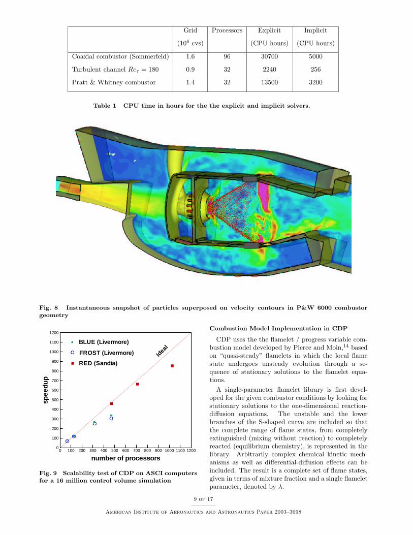
Results for some typical calculations are summa-rized in Table 1. The savings are seen to be significant.
For example, explicit calculation of the cold flow ina coaxial geometry required 320 hours × 96 processors= 30,700 CPU hours on an IBM SP3 machine. Theimplicit code uses around 5,000 CPU hours, which isapproximately a factor of 4 times the time taken by thehighly optimized structured grid solver of Pierce andMoin13 that uses the same time-step. The structuredsolver is of course incapable of handling geometries ascomplex as the Pratt & Whitney combustor (see Fig.8).
One of the main goals in development of the presentLES code was to ensure that the solver scales well upto a high number of processors (in the range of severalhundreds to thousand). Figure 9 shows the results ofa scalability test on several ASCI platforms.
8 of 17
American Institute of Aeronautics and Astronautics Paper 2003–3698
Grid Processors Explicit Implicit
(106 cvs) (CPU hours) (CPU hours)
Coaxial combustor (Sommerfeld) 1.6 96 30700 5000
Turbulent channel Reτ = 180 0.9 32 2240 256
Pratt & Whitney combustor 1.4 32 13500 3200
Table 1 CPU time in hours for the the explicit and implicit solvers.
Fig. 8 Instantaneous snapshot of particles superposed on velocity contours in P&W 6000 combustorgeometry
number of processors
spee
dup
0 100 200 300 400 500 600 700 800 900 1000 1100 12000
100
200
300
400
500
600
700
800
900
1000
1100
1200
Idea
lFROST (Livermore)
RED (Sandia)
BLUE (Livermore)
Fig. 9 Scalability test of CDP on ASCI computersfor a 16 million control volume simulation
Combustion Model Implementation in CDP
CDP uses the the flamelet / progress variable com-bustion model developed by Pierce and Moin,14 basedon “quasi-steady” flamelets in which the local flamestate undergoes unsteady evolution through a se-quence of stationary solutions to the flamelet equa-tions.
A single-parameter flamelet library is first devel-oped for the given combustor conditions by looking forstationary solutions to the one-dimensional reaction-diffusion equations. The unstable and the lowerbranches of the S-shaped curve are included so thatthe complete range of flame states, from completelyextinguished (mixing without reaction) to completelyreacted (equilibrium chemistry), is represented in thelibrary. Arbitrarily complex chemical kinetic mech-anisms as well as differential-diffusion effects can beincluded. The result is a complete set of flame states,given in terms of mixture fraction and a single flameletparameter, denoted by λ.
9 of 17
American Institute of Aeronautics and Astronautics Paper 2003–3698

In this model, in addition to the variable density,momentum, and continuity equations, scalar transportequations are solved for the mixture fraction Z, whichis a conserved scalar, and for the progress variable C,which is a non-conserved scalar. The continuity equa-tion acts as a constraint on the velocity field, withthe time-derivative of density as a source term. Thisconstraint is enforced by the pressure, in a manneranalogous to the enforcement of the incompressibilityconstraint for constant density flows.
Under the model assumptions, all the other fluidflow variables (density, temperature, molecular viscos-ity, molecular diffusivity), chemical species and thereaction source terms in the scalar transport equationsare related to the mixture fraction and the progressvariable through a flamelet library that is precalcu-lated given a specific fuel reaction mechanism and theflow conditions in the combustor. The only require-ment for the quantity chosen to serve as the progressvariable is that it should be a quantity that is repre-sentative of the overall gross flame behavior and thatvaries monotonically with the flame state so that itsvalue uniquely determines it. For instance, in the re-acting flow simulation of methane-air combustion in acoaxial jet combustor, the progress variable is chosenas the product mass fraction C = yCO2 + yH2O.14
Spray module
The droplets are modeled as point particles whichsatisfy Lagrangian equations. They influence the gasphase through source terms in the gas-phase equations.As the particles move, their position is located andeach particle is assigned to a control volume of thegas-phase grid. The gas-phase properties are interpo-lated to the particle location and the particle equationsare advanced. The particles are then relocated, par-ticles that cross interprocessor boundaries are dulytransferred, source terms in the gas-phase equation arecomputed, and the computation is further advanced.
Stochastic Model for Secondary Breakup
Liquid spray atomization plays a crucial role in thecombustion dynamics in gas-turbine combustors. Instandard Lagrangian particle tracking codes, empha-sis is placed on obtaining the correct spray evolutioncharacteristics away from the injector. Only the globalbehavior of the primary atomization, occurring closeto the injector, is considered and the details are notcaptured. The essential features of spray evolution,viz. droplet size distribution, spray angle, and pen-etration depth, are predicted away from the injectorsurface by secondary breakup models. Usually, stan-dard deterministic breakup models based on TaylorAnalogy Breakup (TAB) or wave models are employedin RANS-type computations. Liquid ‘blobs’ with thesize of the injector diameter are introduced into thecombustion chamber and undergo atomization accord-
ing to the balance between aerodynamic and surfacetension forces acting on the liquid phase. Both mod-els are deterministic with ‘single-scale’ production ofnew droplets. In many combustion applications, how-ever, injection of liquid jet takes place at high relativevelocity between the two phases (high initial Webernumber). Under these conditions, intriguing processessuch as turbulence-induced breakup, multiple dropletcollision in the dense spray region, fluctuations dueto cavitating flow inside the injector, etc., contributeto the process of atomization. This results in dropletformation over a large spectrum of droplet-sizes andis not captured by the above models. Predicting thedistribution of droplet sizes at each spray location isimportant for sheet-breakup modeling.
In order to predict the essential global features ofthese complex phenomena, a stochastic approach fordroplet breakup which accounts for a range of product-droplet sizes has been developed by Gorokhovski &Apte.10 Specifically, for a given control volume, thecharacteristic radius of droplets is assumed to be atime-dependent stochastic variable with a given initialdistribution function. The breakup of parent blobsinto secondary droplets is viewed as the temporal andspatial evolution of this distribution function aroundthe parent-droplet size. This distribution functionfollows a certain long-time behavior, which is charac-terized by the dominant mechanism of breakup. Thesize of new droplets is then sampled from the distribu-tion function evaluated at a typical breakup time scaleof the parent drop.
Hybrid Particle-Parcel Technique forSpray Simulations
Performing spray breakup computations using La-grangian tracking of each individual droplet gives riseto a large number of droplets (> 50-100 million) veryclose to the injector. Computing such a large num-ber of droplet trajectories is a formidable task evenwith the largest of supercomputers. In parallel com-putation of complex flows utilizing standard domain-decomposition techniques, the load balancing per pro-cessor is achieved by equally distributing the numberof grid cells among all processors. Lagrangian particle-tracking, however, causes load-imbalance owing to thevarying number of droplets per processor.
In order to overcome the above load balancing prob-lem, the usual approach is to represent a group ofdroplets with similar characteristics (diameter, veloc-ity, temperature, etc.) by a computational particleor ‘parcel’. In addition, one carries the number ofdroplets per parcel as a parameter to be tracked. Sincea parcel represents a group of droplets (of the or-der of 100-1000), the total number of computationalparticles or trajectories to be simulated is reduced sig-nificantly. With breakup, the diameter of the parcel issampled according to the procedure given above and
10 of 17
American Institute of Aeronautics and Astronautics Paper 2003–3698

the number of droplets associated with the particlesis changed in order to conserve mass. This reducesthe total number of computational particles per pro-cessor and increases the computational overhead withsprays by around 20% depending on the number ofparcels used. Each parcel has all the droplet charac-teristics associated with it. The parcels methodologyworks well for RANS-type simulations where one isinterested in time- or ensemble-averaged quantities.For LES, however, we should ideally simulate as manydroplet trajectories as possible in order to obtain time-accurate results.
A hybrid scheme involving the computation of bothindividual droplets and parcels is proposed. The dif-ference between droplets and parcels is simply thenumber of particles associated with them, Npar, whichis unity for droplets. During injection, new particlesadded to the computational domain are pure drops(Npar = 1). These drops move downstream and un-dergo breakup according to the above breakup modeland produce new droplets. This increases the num-ber of computational particles in the domain. In thedense-spray regime, one may obtain a large number ofdroplets in a control volume and its immediate neigh-bors. The basic idea behind the hybrid-approach,is to collect all droplets in a particular control vol-ume and to group them into bins corresponding totheir size and other properties such as velocity, tem-perature, etc. The droplets in bins are then used toform a parcel by conserving mass, momentum and en-ergy. The properties of the parcel are obtained bymass-weighted averaging from individual droplets inthe bin. For this procedure, only those control vol-umes are considered for which the number of dropletsincreases above a certain threshold value. The num-ber of parcels created would depend on the numberof bins and the threshold value used to sample them.The parcel thus created then undergoes breakup ac-cording to the above stochastic sub-grid model. It,however, does not create new parcels. On the otherhand, Npar is increased and the diameter is decreasedby mass-conservation.
The effectiveness of this hybrid approach is demon-strated in the following computations. The implemen-tation of this method in an unstructured LES codegives us the capability of testing and validating thesemodels in realistic industrial geometries for variouscombustors with multiphase flows.
PW Frontend validation Geometry
The stochastic model along with the hybrid particle-parcel approach were used to simulate the spray evo-lution in the Pratt and Whitney injector. The ex-perimental data set was obtained by mounting theinjector in a cylindrical plenum through which gaswith prescribed mass-flow rate was injected. The gasgoes through the main and guide swirler to create a
swirling jet into the atmosphere. Liquid film is injectedthrough the filmer surface which forms an annular ring.The liquid mass-flow rate corresponds to certain oper-ating conditions of the gas-turbine engine. Measure-ments of the droplet distribution and liquid mass fluxin the radial direction at two different axial locationsaway from the injector were performed. Gas-phasestatistics for mean and rms velocities are also avail-able at these locations. The outside air-entrainmentrates were measured and prescribed as inflow condi-tions. A snapshot of the spray evolution in the z = 0plane along with the gas-phase axial velocity contoursis shown in Fig. 10. The hybrid-approach used hereingives a dynamical picture with correct spray angle.Preliminary results show that the liquid mass fluxes attwo downstream locations are in reasonable agreementwith the experimental data. However, a longer-timesample is necessary to match the computational pre-dictions with the experiments.
Integrated SimulationsThe goal of the Multi-Component Integrated Sim-
ulation Project is to couple several components of agas-turbine engine into a single simulation that willeventually include the entire compressor, combustor,and turbine flow paths when the computing power be-comes available. The prediction of multi-componentphenomena, such as compressor/combustor insta-bility, combustor/turbine hot-streak migration, andmain/secondary flow ingestion/interaction, can be im-proved by directly coupling the simulations of all com-ponents. Since each of the components to be coupledhas to be simulated using a solver which requires par-allel computing resources, it is of fundamental impor-tance that the resulting coupled simulation be bothefficient and scalable. In order to achieve this goal, weare paying close attention to the individual scalabil-ity of the component codes (TFLO and CDP) as wellas to the details of the coupling and the load balanc-ing of the resulting calculation. Current efforts havefocused on coupling the gas-turbine combustor andturbine main flow path as well as the turbine mainand secondary-air system flow paths.
In the turbine main and secondary-air system inter-action problem, the ingestion of combustor hot-gasesinto the rim-cavity/secondary-flow path between thehigh-pressure turbine vane and blade can often leadto degradation in durability. Often the combustorhot-streak is designed to be hub-biased (higher tem-peratures near hub) by changing the dilution hole flowsin the burner in order to avoid blade tip/BOAS (BladeOuter Air-Seal) burning. However, as a result, thehot gases from the combustor near the hub can be in-gested into the gap between the high-pressure turbinevane and blade and accumulate in this rim-cavity re-gion. This high- temperature flow can burn the vanehub trailing edge platform and even burn the high-
11 of 17
American Institute of Aeronautics and Astronautics Paper 2003–3698

Fig. 10 Evolution of spray from a PW injector: contours of axial velocity superimposed with particlescatter plot.
pressure turbine blade disk. Disk burning can be amajor concern since it can lead to premature fatigue.Accurate prediction of the flow in this region, includ-ing the amount of flow ingested or purged from thesecondary-flow rim-cavity, and the temperature dis-tributions on the vane/blade hub and blade disk, arecritically important in good design.
Due to the different physics and scales in the variousparts of a turbomachinery engine, it will be neces-sary to increase the fidelity of the physical model inareas such as the combustor. Studies have shownthat capturing of the relevant physical phenomena dur-ing combustion processes can be better accomplishedusing Large Eddy Simulation (LES) rather than themore conventional Reynolds-Averaged Navier-Stokes(RANS) model. This increase in fidelity, however,comes at a high computational cost. From the point ofview of computational simplicity it would be desirableto simulate the complete flowpath using LES. Unfor-tunately, this capability is beyond the computationalpower of the largest supercomputers in the foreseeablefuture. For this reason, a zooming approach is be-ing followed where large portions of the flowpath thatcan be accurately resolved with unsteady RANS sim-ulations (such as the compressor and the turbine) aresolved with TFLO, and those portions that requireLES are solved using CDP. A number of interestingresearch issues arise when interfacing simulations thatuse different physical models. Before actually couplingTFLO and CDP, we have been conducting a number
of exploratory studies using TFLO and a simplified-geometry LES code to solve the fundamental issues inthis coupling. Our efforts in this area are presented inthis section.
Turbine Main/Secondary-Air System IntegratedSimulations
The TFLO code is being used to investigate theinteraction between the main flow-path and the sec-ondary air system flow for a production HPT transonicstage, transition duct, and 1st-vane of the low-pressureturbine (LPT) which were designed based upon therig described earlier in this paper. These simulationscan be carried out using either two separate instancesof the TFLO solver or a single TFLO calculation.The availability of these two options has been usedto validate the multi-code interface we have developed.Thus far, both steady and unsteady integrated simula-tions of the main and secondary air-system flow pathshave been performed. Fig. 11 shows the multi-blockstructured-grid used in the secondary air-system flowpath. The secondary air-system computational gridis point-matched to a grid block constructed to ex-tend across the main flow path between the end ofthe HPT stator hub and the beginning of the rotatingHPT blade hub. Communication between the mainand secondary air-system flows in TFLO does not haveto be performed directly using point-matched grids. Aspecial interface that allows point mismatched gridsto be used across any block boundary15 may be used
12 of 17
American Institute of Aeronautics and Astronautics Paper 2003–3698

as an alternative to point-matched grids in order toeliminate grid stretching or skew problems that mightoccur. This special interface allows different compu-tational grid systems or non-point-matched grids tocommunicate with each other through use of a three-dimensional interpolation process.
Figure 12 shows the temperature contours of thecoupled main/secondary-air system simulation. In thissimulation, the combustor hot-streak is modeled withan inlet temperature profile boundary condition to theturbine main flow-path. Since the peak temperatureis near mid-span in this simulation, the temperature ishigh (shown in red) on the high-pressure turbine vanepressure and suction surfaces and lower on the vanehub and casing endwalls. The high-temperature flownear midspan migrates into the high-pressure turbineblade but is mixed out circumferentially due to thesteady-flow inter-blade-row boundary condition treat-ment. The radial profile of the hot-streak is main-tained, however. As a result, the temperature field inthe blade passage is highest near midspan. The flowfrom the secondary system is at a much lower temper-ature than the turbine main flow path. It enters themain flow path at the hub between the high-pressureturbine vane and blade. As a result, the flow along thehub of the blade and downstream transition duct andlow-pressure turbine vane is cooled. Remnants of thecombustor hot-stream can be seen in Fig. 12 near thelow-pressure turbine first-vane midspan position.
Flow enters the secondary air-system near the cen-terline and mid-way radially in the lower secondaryair-system cavity. This air comes from the high-pressure compressor bleed air. In addition, air en-ters the tangential on-board injection (TOBI) nozzlefrom the combustor burner bypass. Flow exists thehigh-pressure secondary air-system near the centerlinewhere it passes to the low-pressure turbine secondaryair-system. In addition, flow exists between the TOBIpump and the blade disk near the top of the TOBIpump where it would proceed into the high-pressureturbine blade as film-cooling air. Finally, much of theair from the secondary air-system exits into the mainflow-path at the top of the rim-cavity. This air is crit-ical to maintain a positive purge from the secondaryair-system into the main flow-path in order to keepcombustor hot gases from being ingested into the rim-cavity and burning the blade disk.
RANS-LES Integrated Simulations
The integration of two flow solvers based on such dif-ferent modeling approaches as the Reynolds-AveragedNavier Stokes (RANS) approach used in our turboma-chinery analysis and Large Eddy Simulations (LES)used for the combustor presents a very challengingproblem. In order to represent flow physics accu-rately, boundary conditions between zones with dif-ferent models have to be carefully formulated.
Two different LES flow solvers are mainly in useat CITS. One is the unstructured CDP flow solver,which has been already described before. The other isa structured single-block flow solver written by CharlesPierce.16 The LES formulation in this latter code isbased on a low-Mach number formulation, and thusis very similar to the formulation of the CDP solver.Although a single-block structured LES flow solver isdifficult to apply to the complex geometries usuallyfound in industrial devices, the low computational costassociated with a structured LES flow solver has al-lowed us to explore the generation of LES boundaryconditions from RANS computations in depth. Hence,it is an ideal testbed for optimizing the coupling pro-cess.
The LES routines handling the interface were writ-ten in a very generic fashion in order for them tobe portable to the CDP flow solver. All communi-cation routines follow the algorithms defined by themulti-code interface15 which will enable compatibilitybetween TFLO, NCC, the structured LES code andCDP.
LES Outflow Conditions from a RANS Zone
The problem of imposing RANS velocity profiles atthe outflow of an LES computation has been describedin.17 The Reynolds-Averaged flow solution from theRANS computation is imposed on the developing LESsolution by using virtual body forces at the outflowboundary of the LES domain:
Fi(x) =1τF
(ui,RANS(x)− ui,LES(x)) , (1)
with ui,RANS being the solution of the RANS flow solvercomputed in an overlap region between the LES andRANS domains, and ui,LES is the time-average of theLES solution over a trailing time-window. This bodyforce ensures that the velocity profiles at the outlet ofthe LES domain fulfill the same statistical propertiesas the velocity profiles in an overlap region computedby a RANS simulation downstream. This makes itpossible to take upstream effects of downstream flowalterations into account.
Numerical Experiment: Swirl Flow
In order to assess the accuracy and the applicabil-ity of integrated flow computations to complex flows,a swirl flow has been computed with a combination ofthe two flow solvers. A swirl flow was chosen, becausethis is typical of gas turbine combustion chambers and,due to its sensitivity to boundary conditions, it pro-vides an excellent test-case for the accuracy of thedeveloped boundary conditions and to validate the im-portance of integrated flow simulations.
In order to assess the accuracy of the LES bound-ary conditions, a numerical experiment was performedwhich is similar to the simulations performed by
13 of 17
American Institute of Aeronautics and Astronautics Paper 2003–3698

Fig. 11 Multi-Block Computational Grid Used in Integrated Main/Secondary-Air System Simulation
Schluter et al.17 to study LES outflow boundary con-ditions. A swirl flow at an expansion with a subsequentcontraction three diameters D downstream of the ex-pansion is considered (Fig. 13a). Inlet velocity profilesare taken from an actual experiment in a similar ge-ometry.18 The swirl number of the flow is S = 0.3,which is just supercritical, meaning that vortex break-down takes place and a recirculation zone develops.The extension and strength of this recirculation zone isstrongly influenced by the presence of the downstreamcontraction. The simplicity of this test-case makes itpossible to perform an LES computation of the com-plete geometry so that an ’exact’ solution of the flowfield is known.
In a validation simulation, only the expansion partof the domain (Figure 13b) will be computed withthe LES solver. Experience shows that the solutiondiffers substantially if the downstream contraction isneglected.
To account for the effect of the downstream contrac-tion, the LES flow solver is coupled with the TFLORANS flow solver which takes care of the computa-tion in the remaining part of the domain (Fig. 13c). Ifthe coupling of the two codes is accurately performed,then this coupled simulation should recover the solu-tion performed for the entire domain using the LEScode alone.
Integrated LES/RANS Computations
Fig. 14 shows the velocity profiles obtained by anintegrated LES-RANS computation. The swirl flowat the expansion is computed by the LES flow solverwhile the contraction is computed with the RANS flowsolver TFLO. The velocity profiles provided by theintegrated LES/RANS-computation (solid lines) areessentially identical to the velocity profiles computedby the LES of the entire domain (circles).
This computation is to the authors’ knowledge thefirst successful integration of two separate flow solvers,one based on the RANS approach and the other on theLES approach.
AcknowledgmentsThis work has been supported by the Department of
Energy ASCI ASAP program under contract B341491from the Lawrence Livermore Laboratory. The au-thors would like to acknowledge the contributions of allthe PIs at the Center for Integrated Turbulence Simu-lations: Profs Moin, Pitsch, Eaton, Jameson, Durbin,Davis, Mahesh, Dally and Hanrahan. Major portionsof this paper represent their contributions to our 2002Annual Report. This work has also been the productof the collaboration of many research associates, andpostdoctoral and graduate students without whom theresults presented in this paper would not have been
14 of 17
American Institute of Aeronautics and Astronautics Paper 2003–3698
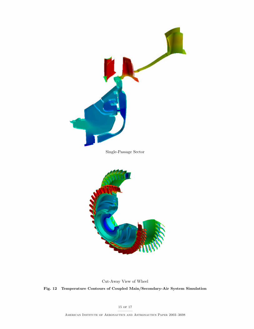
Single-Passage Sector
Cut-Away View of Wheel
Fig. 12 Temperature Contours of Coupled Main/Secondary-Air System Simulation
15 of 17
American Institute of Aeronautics and Astronautics Paper 2003–3698

������������������������������������������������������������������������������������������������������������������������������������
��������������������������������������������������������������������������������������������������������������������������������������������
����������������������������������������������������������������������������
����������������������������������������������������������������������������������������������������������������������������������������������������
����������������������������������������������������������������������������
�����������������������������������������������������������������������������������������������������������������������������������������������������������������������������������������
contraction
.
a)
b)��������������������������������������������������������������������������������������������������������������������
��������������������������������������������������������������������������������������������������������������������
������������������������������������������������������������������������������������������
������������������������������������������������������������������������������������������������������������������������������������
��������������������������������������������������������������������������������������������������������������������������������������������
LES+bodyforceLES
����������������������������������������������������������������������������
����������������������������������������������������������������������������������������������������������������������������������������������������
����������������������������������������������������������������������������
�����������������������������������������������������������������������������������������������������������������������������������������������������������������������������������������
contraction
LES LES or RANS
contraction
LES or RANS
u (t)i
u (x,t)i
c)
Fig. 13 Geometry for integrated LES/RANS computations: a) full geometry, b) reduced LES domain,c) schematic splitting of domain to two computational domains
possible. We recognize their efforts as fundamental tothe continued success of our Center.
References1Jameson, A. & Caughey, D. A., 2001, How Many Steps are
Required to Solve the Euler Equations of Steady, CompressibleFlow: In Search of a Fast Algorithm. AIAA Paper 2001-2673,AIAA 15th Computational Fluid Dynamics Conference, Ana-heim, California, June 11-14, 2002.
2“Annual Technical Report ”, 2002, Center for IntegratedTurbulence Simulations, edited by W. C. Reynolds, M. Faticaand J. J. Alonso.
3Davis, R. L, Yao, J., Clark, J. P., Stetson, G., Alonso, J.J., Jameson, A., Haldeman, C. W., and Dunn, M. G., 2002,“Unsteady Interaction between a Transonic Turbine Stage andDownstream Components”, ASME Paper GT-2002-30364.
4Clark, J. P., Stetson, G. M., Magge, S. S., Ni, R. H., Halde-man, C. W., and Dunn, M. G., 2000, “The Effect of AirfoilScaling on the Predicted Unsteady Loading on the Blade of a 1and 1/2 Stage Transonic Turbine and a Comparison with Ex-perimental Results,” ASME Paper 2000-GT-0446, ASME TurboExpo 2000, Munich, Germany.
5Wu X. & Durbin P.A., 2001, Numerical simulation of heattransfer in a transitional boundary layer with passing wakes, J.Fluid Mech. 446:199–228.
6Jameson, A., 1983, Solution of the Euler Equations forTwo-dimensional, Transonic Flow by a Multigrid Method. Appl.Math. Comp. Vol. 13, pp. 327–356.
7McMullen, M. S., 2003 The Application of Non-Linear Fre-quency Domain Methods to the Euler and Navier-Stokes Equa-tions. Stanford University Ph.D. Thesis, March 2003.
8Brandt, A., 1977, Multi-Level Adaptive Solution to Bound-ary Value Problems, Math. Comp., Vol. 31, No. 138, pp. 333-390.
9Germano M., Piomelli U., Moin P., and Cabot W., 1991, Adynamic subgrid-scale eddy viscosity model. Phys. Fluids, A(3(7)):1760–1765.
10Gorokhovski, M. & Apte, S.V., 2001, Stochastic sub-gridmodeling of drop breakup for LES of atomizing spray. CTRAnnual Research Briefs, 169-176.
11Mahesh, K., Constantinescu G. & Moin, P., 2000, LargeEddy Simulation of gas turbine combustors. CTR Annual Re-search Briefs, 219-228.
12Mahesh, K., Constantinescu G., Apte, S., Iaccarino G.&
Moin, P., 2001, Large Eddy Simulation of gas turbine combus-tors. CTR Annual Research Briefs, 3-17.
13Pierce C. D. & Moin P., 1998, Large eddy simulation of aconfined jet with swirl and heat release. AIAA Paper, 98-2892.
14Pierce, C. D. & Moin, P., 2001, Progress variable approachfor large eddy simulation of turbulent combustion. Report TF -80, Flow Physics and Computation Division, Mechanical Engi-neering Dept., Stanford University, Stanford, California.
15Shankaran, S., Alonso, J. J., Liou M. F., Liu, N. S.,Davis, R., 2001, A Multi-Code Coupling Interface for Com-bustor/Turbomachinery Simulations, 39th AIAA Aerospace Sci-ences Meeting and Exhibit, AIAA Paper 2001-0974, Reno. NV.
16Pierce C. D. and Moin P., 1998, Large eddy simulation ofa confined coaxial jet with swirl and heat release. AIAA Paper,(1998-2892)
17Schluter J. U., Pitsch H., and Moin P., 2002, Consistentboundary conditions for integrated LES/RANS simulations:LES outflow conditions. AIAA paper, (2002-3121), 32nd AIAAFluid Dynamics Conference, June 24-27 2002, St, Louis, MO.
18Dellenback P. A., Metzger D. E. and Neitzel G. P., 1998,Measurements in turbulent swirling flow through an abrupt ax-isymmetric expansion. AIAA Journal, 26(6):669–681.
16 of 17
American Institute of Aeronautics and Astronautics Paper 2003–3698

0.00
0.50
1.00x/D= −0.5 0.5 1.51.0 2.52.0 3.0
Ux inte
rfac
e
0.00
0.50
1.00x/D= −0.5 0.5 1.51.0 2.52.0 3.0
Uφ inte
rfac
e
Fig. 14 Integrated LES/RANS computations. Velocity components for different downstream positions.circles: LES of full geometry (Fig. 13a), dashed line: LES of expansion (Fig. 13b), solid line: integratedLES-RANS computation (Fig. 13c)
17 of 17
American Institute of Aeronautics and Astronautics Paper 2003–3698