−i−€¦ · Commentary: Challenges of solving the problem of soil and groundwater contamination...
60
Transcript of −i−€¦ · Commentary: Challenges of solving the problem of soil and groundwater contamination...


− i −
Highlights of the Papers in Synthesiology
Synthesiology is a journal that describes the objectives, specific scenarios, and procedures of research activities that attempt to utilize the results in society, in particular, the process of synthesis and integration of elemental technologies for practical application. To allow the readers to see the value of the papers in a glance, the highlights of the papers that characterize Synthesiology have been extracted.
Synthesiology Editorial Board
Research paper: Towards an ideal world with superconductivity—Current status and prospects for rare-earth barium copper oxide superconducting tapes—Teruo IZUMI
This paper describes the current situation of the development of tape material using high-temperature superconductors that is highly expected as a dream technology, and the hurdles toward its realization. The description of the scenario in which integration of diverse elemental technologies is conducted to present is interesting, but how to gain the “users’commitment” that is given as the important point toward future realization is perhaps a common point in realizing other new materials.
Research paper: Development and popularization of QR code—Code development pursuing reading performance and market forming by open strategy—Masahiro HARA
This paper discusses not only the scenario for the development of the QR code that is widely used as a two-dimensional barcode, but also the strategy for its diffusion. One often thinks that excellent technology should be monopolized by patents, but this is an interesting case in which disclosing patent rights led to wider diffusion. This paper gives a strong impression that no matter how excellent a technology, without a strategy for diffusion and branding, there will be no market formation.
Research paper: Development of a compact all-solid-state lithium secondary battery using single-crystal electrolyte—Towards realizing oxide-type all-solid-state lithium secondary batteries—Kunimitsu KATAOKA et al.The use of lithium secondary batteries is increasing in smart phones and automobiles, and next-generation all-solid-state lithium secondary batteries are gathering attention since they will enable high capacity, high voltage, and long lifespan. This paper proposes a scenario of problem solving to realize an all-solid-state lithium secondary battery that uses oxide as its electrolyte. It is expected for use in IoT, wearables, and for medical purposes.
Commentary: Challenges of solving the problem of soil and groundwater contamination—An interdisciplinary approach—Ming ZHANG
As seen in the soil contamination problem of the Toyosu Market, the soil and groundwater contamination is becoming diverse and complex. It is a problem that can no longer be solved simply by advancing decontamination and countermeasure technologies. This article states that it is necessary to make advances in investigation and assessment technologies along with risk assessment and management technologies, and to comprehensively consider the environmental, economic, and social aspects to solve the problem.
Electronic journalURL J-Stagehttp://www.aist.go.jp/aist_e/research_results/publications/synthesiology_e/ https://www.jstage.jst.go.jp/browse/syntheng
− ii −
Synthesiology – English edition Vol.12 No.1 (Aug. 2019)Contents
Highlights of the Papers in SynthesiologyContribution Future of Synthesiology 1 – 5 - - - H. YOSHIKAWA
Research papers Towards an ideal world with superconductivity 6 – 18 —Current status and prospects for rare-earth barium copper oxide superconducting tapes— - - - T. IZUMI
Development and popularization of QR code 19 – 28 —Code development pursuing reading performance and market forming by open strategy— - - - M. HARA
Development of a compact all-solid-state lithium secondary battery using single-crystal electrolyte 29 – 40 —Towards realizing oxide-type all-solid-state lithium secondary batteries—
- - - K. KATAOKA, T. AKAO, H. NAGATA, H. NAGAI, J. AKIMOTO and J. AKEDO
Commentary Challenges of solving the problem of soil and groundwater contamination 41 – 50 —An interdisciplinary approach—
- - - M. ZHANG
Editorial policy 51 – 52Instructions for authors 53 – 54Letter from the editor 55Aim of Synthesiology

Contribution
−1−Synthesiology - English edition Vol.12 No.1 pp.1 –5 (Aug. 2019)
knowledge, because research has been conducted based on officially recognized methods. However, there is perhaps no officially recognized method for the usage of knowledge, and therefore, the results obtained by using the knowledge is not recognized as official knowledge like the results of scientific research, and therefore, documentation of the use of knowledge cannot be accepted as a paper.
Put in simple terms, scientific research is a process of coming across a phenomenon that one does not understand, and finding a principle that drives this phenomenon and provides a comprehensive explanation. If the discovered principle is new, it can be registered as something that may become a scientific law. Scientific knowledge is a set of laws, and the objective of science as a whole is to systematize the set of laws. Humankind discovered this method over a long period of history. A phenomenon that cannot be understood is carefully observed as much as possible, and assuming that there is a general principle that generates the observation result, an attempt is made to explain the phenomenon using assumptions. If an explanation is provided, the principle is called a hypothesis and is set as a candidate of law. The hypothesis remains a hypothesis unless it is overturned by some other phenomenon, and it will be officially called a law if it becomes incorporated without contradiction into the system of laws. Speculation using this law is recognized as being correct.
2 Foresight of Synthesiology
On the other hand, human activities including making a new machine or device, adopting a new mode of behavior, or establishing a set of regulations, collectively called “artifact making,” is an act of creating phenomena that are meaningful to people. This meaningfulness is the function of artifacts. In general, this meaningful phenomenon is synthesis of diverse elemental phenomena. The selected elemental phenomena not only depend on scientific laws, but also are gathered through empirical knowledge, conception, insight, intuition, or social motivation, and anything that may be unexplainable by science can be incorporated freely. This is clear from the example that a steam engine was created before the laws of thermodynamics were established, and even currently, one
We have reached the tenth anniversary since the launch of the journal Synthesiology. During these 10 years, the journal published many papers on the results of synthetic research. Papers were also published on the proposals and research that analyzes the essence of synthetic research[1][2]: What is synthesiology? What is the structure of synthetic research? What are the conditions under which a research paper may become useful knowledge to society? Such papers provide important guidance to those who are attempting to write papers on synthetic research. Synthesis is not only an important intellectual activity for people who produce useful things and contribute to society. It is also becoming clear that the results may bring forth major effect on society as well as the natural environment and earth, and there is increased consciousness that synthetic actions may have adverse effects on society and nature. Against this background, I would like to reflect on the significance of the journal that was launched 10 years ago with the hopes that the scientific community and society will recognize synthetic research, a unique type of research, similar to scientific research that is backed by a long history.
1 Scientific papers
When I first became an editor at an engineering society, the following was said: “You cannot write a paper on just making something.” In fact, such papers were rejected for that very reason. There was much discussion on this subject, and I think the consensus that emerged through the discussions was that the thought process that goes into making something is “not scientific.” This mode of thought originates from the idea that the research that is published as papers should follow scientific methodologies. In practice, many artifacts that are human inventions and had great impact on the world, including machines, electronic devices, and materials, were perhaps made by using the knowledge of science, but were not necessarily created in accordance with the officially recognized scientific methods. In fact, the making processes have never been presented to the world in a paper form, and only the results have been manifested as artifacts or in the form of patents in part. For example, no one wrote a paper about the steam engine, but it appeared as a machine, and was put to work thereafter. In science, a paper is accepted as a scientific result, which in turn is recognized as official
Future of Synthesiology
[Translation from Synthesiology, Vol.12, No.1, p.1–5 (2019)]
Hiroyuki YOSHIKAWA
Center for Research and Development Strategy Japan Science and Technology Agency Senior Fellow Science Plaza(10F), 5-3 Yonbancho, Chiyoda-ku 102-8666, Japan
Contribution : Future of Synthesiology (H. YOSHIKAWA)
−2−
Synthesiology - English edition Vol.12 No.1 (2019)
does not know all the scientific laws of various phenomena that support the artificial system in which efficiency is achieved in economic activities through the introduction of information systems.
As it can be seen, functions that one wishes to have are created by selecting and synthesizing necessary phenomena, and one may select the phenomena as long as he/she knows about them, without knowing the laws that govern the particular phenomena or without having a systemized methodology for combining the phenomena. The inability to express what drives the process of artifact making as a general methodology is the reason that one cannot write a paper just about making a machine.
The author believes the reason for “not being able to make an artifact well” is because humankind does not know exactly how an artifact is made, or one cannot provide a lucid explanation for the making process like for science. There is a reason for it being considered not done well, despite the fact that we are producing large amounts of artifacts. That is because several different things are made for the same intention, and it is impossible to evaluate the validity of the things that had been made. As a result, the evaluation is left to society, but looking at examples in which a flood of artifacts causes environmental destruction, it cannot be said that we are doing it well.
Moreover, we have already passed the stage in which we can simply say that we are doing it poorly. Creation of artifacts has given humankind benefits as intended, and that is the basis of prosperity of humankind. On the other hand, many problems are generated and shared by people, a representative one being global warming, but there are other issues for which urgent measures must be taken. These are side effects in which unintended functions were created, and many present the limit of earth’s tolerance (planetary boundary, J. Rockstrom[3]) from the viewpoint of resilience. They include global problems such as resource depletion or increased natural disasters, as well as regional problems such as poverty, wealth difference, famine, disease, short life expectancy, and conflicts. Looking at their causes, they are all based on human activities. Modern competitive industry that applied scientific knowledge to industry created an uneven distribution of technological levels and generated wealth gaps. Poverty is born in such a setting. The competition of unlimited expansion due to increasing population affected the air, sea, and ecosystem, and as a result, it is causing the deterioration of the earth environment. Currently, humankind has become aware of the problem, and although it took decades to acknowledge global warming, we have reached a global agreement to take countermeasures. While the newly proposed Sustainable Development Goals (SDGs) of the United Nations is not for the world to take action after agreeing on the driving principle as in global warming, but
points out the immediate problematic phenomena and urges the region to solve the problem.
In the case of global warming, the policy is to restrict the amount of carbon dioxide emission to remove the inconvenient phenomena that have been generated. On the other hand, SDGs is a policy of working to solve the problem utilizing the experiences of the regions that succeeded in solving similar problems. Basically, the solution is sought by suppressing activities or by transferring existing knowledge. Are suppression of existing methods and regional transfer of knowledge the only methods for solving the current earth problems that are generated by artifact making?
3 Philosophy of Synthesiology
Recently, design orientation is becoming a topic in university education. This is based on the thought that one must increase the ability to design in order to meet the social demands, and the author thinks there is an important meaning in this. Design is a concept that covers the act of “artifact making” in a wide sense of the meaning as explained above, transcending the realm of development and design conceived conventionally by engineers. It includes planning for various activities in society, for example, proposal of laws and policies, business planning, conceptualization of artistic production, university policies, disease treatment, and personal life plans. These are synthetic activities that are contraposed to analytical activities in science. It also means that “becoming adept” at these activities is now recognized as a social goal.
Hence, design orientation requires synthetic action to be not just implicitly recognized but to be explicitly recognized as something that is important to people, and then be objectified and be thought about. If that is the case, Synthesiology is already ahead by 10 years concerning the current rising interest in design, and it can be said that many valuable findings pertaining to design have been accumulated.
What are the papers published in Synthesiology like? The author surveyed the papers a few years after the launch of the journal, and they will be described as follows.
A scientific paper takes the following form: a subject is selected, a phenomenon caused by the subject is observed, observation results are analyzed, the phenomenon is explained by existing laws or some new law is proposed as a hypothesis, and application of research results is referred. For example, in life sciences, the role of a component within an organic phenomenon is clarified, and treatment for a disease is proposed based on this knowledge, in the course of clarifying how components work in an organism.
Though, in a scientific paper, the “application of knowledge”

Contribution : Future of Synthesiology (H. YOSHIKAWA)
−3−Synthesiology - English edition Vol.12 No.1 (2019)
is discussed in the final chapter, in Synthesiology, “application of knowledge” is written first as what is demanded by society. First, why society demands such technology is stated. Scientific and technological knowledge needed to solve an issue is searched, and the knowledge that lacks is pursued by new research projects. Or, hidden knowledge is excavated by freely roaming in society. Based on such a background, a scenario is written as a hypothesis, but the description must be logical and consistency of meaning is required.
A scenario is a hypothesis that presents social issues and offers solutions. A paper is written when results are obtained as realization of the hypothesis. The hypothesis induces unique R&D, and the usefulness of the results obtained from research is confirmed, and the written paper includes the originality of the hypothesis and the originality of the solution.
The structures of the submitted papers are unique and the contents are diverse, but the viewpoints of research have something in common. The viewpoints can be categorized as follows: new function(s), risks associated with the new function(s), design of an artifact (in a wide sense) to realize the function(s), manufacturing based on the design, unique measurement, and social technology to implement them in society. Each viewpoint has original points or items. While the contents vary according to paper, the characteristics of the paper’s intent can be understood by writing out the viewpoints of research along with the items using categories obtained as a result of a survey as a template, and by specifying the corresponding items. For example, the paper on antifreeze protein in Reference [4] that was published in Volume 1 Issue 1 can be written out as Fig. 1.
The viewpoints of Fig. 1 should be realized in research, and the viewpoints necessary for achievement are shown on the template. In this research, the goal of developing an excellent freezing method necessary for storage and transportation without damaging the quality of foodstuff is realized by using scientific knowledge discovered in basic research,. When shown like this, the relationship with other research with different goals can be visualized. In other words, synthetic research that was thought to have no mutual relationship with anything else can be understood as something that does have a common, original structure and necessary information. It is hoped that such examples will rectify the situation in which scientific research that follows scientific methods is trusted and papers can be published as scientific papers as a social rule, whereas synthetic research not following scientific methods does not have a journal in which to publish. This is discussed in detail in papers of References [1] and [2] by Ono, Akamatsu, Kobayashi, et al.
The viewpoints being the items that must be realized means that they are the required functions in design in a
wide sense as mentioned in this chapter. If items can be formalized as a template, this allows expectation of adept synthetic activity as mentioned above by creating “rules of requirement that covers all viewpoints” and allows avoidance of aforementioned side effects as well as realization of goal functions. This can be considered the philosophy of synthesiology.
If this becomes possible, the removal of side effects shifts to regulation of post facto actions and transfer of knowledge, and these can be embedded within the design of action. This must be considered particularly in SDGs planning. There, diverse knowledge and technology will be applied to new regions, but if they are applied without considering the uniqueness of the region, dangerous side effects may be forecasted. The removal of risks of side effects at the design stage is essential.
Fig. 1 Viewpoints of synthetic research
Medical sciences
Energy &
environment
Life sciences
Nanotech m
aterials
Information &
com
munication
4. Manufacturing
StandardManufacturing machineSpatial arrangement
Processing method (Removal, addition, deformation, joining, separation)
Mass production
6. Social technology
Industry-academia collaborationResearch institution/organization R&D investment
Science and technology policy
Intellectual property rights Development cost
5. Measurement New method
Total observation
VisualizationPredictionSimulationEnvironment/lifespan test
Structural analysisMicroscope
New function Strengthening function1. Function
Resource savingEnergy saving
3RLow environmental load
High reliabilityLong lifespanDownsizing
Safety Digital divideEnvironmental pollutionNano-risk2. Risk
3. Design
Computational science
Research strategy SystemTheoryDiscipline design
Knowledge baseDiscipline-transcending design
Contribution : Future of Synthesiology (H. YOSHIKAWA)
−4−
Synthesiology - English edition Vol.12 No.1 (2019)
4 General design theory
Here, we again look at the thought on papers that rely on scientific logic that conveys that “one cannot write a paper just about making something.” In science, research methods are openly shared among scientists, and the research that follows these methods is written as scientific papers, and this is the basis that guarantees the validity of the papers. In contrast, synthesis uses methods that include experience, intuit ion, insight, and feelings that are elements not recognized as being logical, and therefore one is told that the results cannot be considered valid.
This requires some explanation. In scientific research, a conclusion is reached for a certain phenomenon through experiments that eliminate noise, observation with as much precision as possible, and discussion that follows deductive reasoning. Since the precision of observation is always subject to error, inductive reasoning is also used. Up to this point a paper can be written, but the paper may expand the application range of the results to phenomena for which experiments have not been done. If the paper states that the finding is a law, then a hypothesis is proposed, but it is said that the thought process involved can only be from intuition or insight. Here, deduction and induction are not useful as reasoning, and hypothesis formation (abduction) is used. Abduction is fallible, or subject to mistakes. A proposal of a hypothesis, which is the most important part of scientific research, is a fallible abduction in terms of reasoning, and in this case, the thinking process of the scientist is mainly intuition and insight.
How synthetic research is different from science should be questioned. The answer is “it is the same.” However, the argument that synthesis cannot be written as a paper is not necessarily wrong. In fact, in scientific research, which part is abduction in the thought process is explicitly shown in the law proposed by abduction. Moreover a hypothesis is not negated unless there is objection raised by other researchers or the researcher him/herself. It is gradually recognized as law after several verifications, and it is shown that the relationship to other related laws is consistent. Of course, the law may be rewritten through new viewpoints, and that is the progress of science.
Considering that science holds such a background, why does the same synthetic research not become papers? That is because the same hypothesis is not confirmed by careful experiments and observation as in science. In the case of science, if confirmation is made within the range of limited experiments, it is temporarily set as a correct hypothesis, and it will continue to be a valid hypothesis unless it is disproved by other experiments. However, in the case of synthetic activity of artifact making, strict experiments and observation with ever-increasing precision are impossible.
We have a custom of setting as the primary condition for a created artifact the fulfillment of the desired functions. However, one cannot definitively speak of its validity due to the instability of the place that it is used, uncertainty of observation, as well as the vagueness of interpretation of the functions set as its objective. Moreover, it is extremely difficult to confirm the appearance of “unexpected functions” that corresponds to application to new phenomena in science.
In practice, the evaluation of validity of an artifact is left to society in which the user resides. If the artifact continues to be used without rejection, it is concluded that the artifact is valid. Of course, when times change and the standard of evaluation changes, it may be rejected, but that is the same as the rejection of old theories in place of new ones in science.
From this, a strategy is brought about for having synthetic research accepted as papers. This is a strategy in which the realization process of the goal is clearly stated including the expression of functions set as the goal, the process of finding the elements to realize those functions, the group of phenomena used to realize the elemental functions, and the synthesis of these phenomena. In which place abduction is used is also clarified. It is in a form that guarantees the possibility of criticism at all steps of this process. When the expression that can take criticism is able to face all objections thrown by society as well as the researchers of the same discipline, the synthesis result will be given the status of hypothesis as in science. However, in scientific research, there are many cases in which the phenomenon that cannot be explained is made clear by using existing laws, and in those cases, deductive logic is mainly used. Abduction is the issue when proposing a new law, but in synthetic research, more intellectual work is required than in scientific papers because abductive reasoning must be used in all.
When acceptance or rejection of an artifact is determined at the place of use, it is hoped that social judgment will be made easier if the logical structure of the process of artifact making is explicitly expressed for judgement. In the use of scientific knowledge, for example, in energy issues, quickly providing information to the researchers studying climate change could have been possible by clearly indicating the scientific knowledge known for a long time that burning fossil fuel generates carbon dioxide, even if it was not related to energy extraction that was the function set as the goal. In recent research for the replacement of human action by information technology, the efficiency can be confirmed by experiment at the place of production, but the idea that the living environment will be improved by introducing information technology to homes is made by intuition. In this case, it should be explicitly presented that the effect of connection with external information on humans cannot be explained scientifically, and it is necessary to show society that the evaluation of its effect is unconfirmed. In Synthesiology

Contribution : Future of Synthesiology (H. YOSHIKAWA)
−5−Synthesiology - English edition Vol.12 No.1 (2019)
Author
Hiroyuki YOSHIKAWAEngages in the research of design, manufacturing, and conservation. In design science, pioneered the “general design theory” that expresses the design process using topology and built the foundat ion of intel lectual CAD. In manufacturing science, suggested the presence of common basic discipline a mong ma nu fac t u r i ng i ndu s t r ie s , proposed the intelligent manufacturing system (IMS), and lead the program for 10 years. In conservation science, defi ned the general structure of conservation and created the prototype for conservation robot MOOTY. Joined AIST in 2001. As the President of AIST, established the outline of a research center that engages in Full Research to shift emphasis to sustainable industry, based on the 10 rules of research management. President, Open University of Japan; Chairman, Science Council of Japan; Chairman, Japan Society for the Promotion of Science; Chairman, International Academy for Production Engineering [College International pour la Recherche en Productique (CIRP)]; and Chairman, International Council for Science (ICSU). Currently, Supreme Advisor, AIST and Project Fellow, Center for Research and Development Strategy, Japan Science and Technology Agency.
References
[1] N. Kobayashi, M. Akamatsu, M. Okaji, S. Togashi, K. Harada and N. Yumoto: Analysis of synthetic approaches descr ibed in papers of the journal Synthesiology— Towards establishing synthesiological methodology for bridging the gap between scientific research results and society, Synthesiology, 5 (1), 36–52 (2012) (in Japanese) [Synthesiology English edition, 5 (1), 37–55 (2012)].
[2] A. Ono, M. Akamatsu and N. Kobayashi: Scenario in synthetic-type research: Its role and description—An investigation from Synthesiology papers, Synthesiology, 9 (1), 26–38 (2016) (in Japanese) [Synthesiology English edition, 9 (1), 27–41 (2016)].
[3] J. Rockström, W. Steffen, K. Noone, Å. Persson, F. S. Chapin III, E. F. Lambin, T. M. Lenton, M. Scheffer, C. Folke, H. J. Schellnhuber, B. Nykvist, C. A. de Wit, T. Hughes, S. van der Leeuw, H. Rodhe, S. Sörlin, P. K. Snyder, R. Costanza, U. Svedin, M. Falkenmark, L. Karlberg, R. W. Corell, V. J. Fabry, J. Hansen, B. Walker, D. Liverman,
papers, the explicit statements of such viewpoints are written not only as scenarios but also as risk estimation by prediction of functions, and papers are valuable because discussions unseen anywhere else are conducted on issues based on the aforementioned viewpoints.
The conclusion here is that it is important to set the mind on this point of view when writing for Synthesiology, but this problem is actually an issue handled in the school of general design that discusses the defi nition of synthesis. It is expected that research of general design that is different from science and determination of the format of the paper of synthetic research will be done coordinately.
K. Richardson, P. Crutzen and J. A. Foley: A safe operating space for humanity, Nature, 461, 472–475 (2009).
[4] Y. Nishimiya, Y. Mie, Y. Hirano, H. Kondo, A. Miura, and S. Tsuda: Mass preparation and technological development of a nt i f reeze prote i n —Towa rd a p r ac t ica l u se of biomolecules, Synthesiology, 1 (1), 7–14 (2008) (in Japanese) [Synthesiology English edition, 1 (1), 7–14 (2008)].
Research paper
−6−Synthesiology - English edition Vol.12 No.1 pp.6–18 (Aug. 2019)
However, as the energy source shifts from natural gas to shale gas, the price has skyrocketed and has become very expensive, and the supply is becoming unstable. Moreover, since it is ultra-low in temperature, extremely low specific heat is another problem. The heat generated or entered by accidental thermal agitation easily raises the temperature, and the temperature may surpass Tc and cause a phenomenon called quench in which superconductivity is rapidly lost. Both are issues that arise from ultra-low temperature, and the discovery of materials that show superconductivity at high temperature was long awaited.
As the search continued, J. G. Bednorz and K. A. Müller of Germany discovered a superconductor of a new material with high Tc (high-temperature superconductor) in 1986.[2] While the previous superconductors were all metal materials, the material they discovered was an oxide La2-xBaxCuO4. When they found this material, they were not looking for superconductors but were actually in the process of developing a conductor. In this material, the temperature at which zero resistance was reached was about 10 K, and it was not so high compared to the metal materials. Therefore, it did not make news at the time of its discovery. However, Professor Shoji Tanaka of Tokyo University (at the time) focused on the point that the temperature at which the resistance began to fall was over 30 K, and by surveying the materials that had similar composition to this material, he discovered a new superconductor that surpassed the Tc limit as predicted by the Bardeen-Cooper-Schrieffer (BCS) theory.[3] Since then, new superconductors were found, and some of them had Tc that surpassed the boiling point of liquid nitrogen (77 K),[4]–[6] and there was expectation for wider-ranging applications past the
1 Introduction
Superconductivity, discovered in mercury by Heike Kamerlingh Onnes of the Netherlands in 1911, was found in the process of creating liquefied helium.[1] Superconductors have been expected to be dream materials, since superconductivity allows transfer of electric energy at zero resistance.
In superconductivity, there are three critical conditions: critical temperature (Tc: the maximum temperature at which superconductivity is revealed); critical current density (Jc: the limit value of current per unit cross-sectional area at which superconductivity can be maintained); and critical magnetic field (Hc: the limit value of magnetic fields at which superconductivity can be maintained). Among these three conditions, Tc and Hc are physical properties that are essentially determined by the material. There are two types of superconductors, type I and type II. In a type I superconductor, superconductivity immediately fails when Hc is reached at relatively low magnetic field, while a type II superconductor has two Hc values, and is able to maintain superconductivity to relatively high critical field (Hc2) as some of the magnetic f lux infiltrates inside the superconductor when the magnetic field surpasses the lower critical field (Hc1). Therefore, in practice, the materials with high Tc and Hc2 are selected for the type II superconductor, and development has been done to achieve high Jc. As a result, NbTi and Nb3Sn are now being used for magnetic resonance imaging (MRI), MAGLEV, and others. However, since Tc is 20 K or less, these materials must be kept in liquid helium (boiling point 4.2 K). Liquid helium is obtained as a by-product of natural gas, and in Japan, it is mostly imported.
—Current status and prospects for rare-earth barium copper oxide superconducting tapes—
We review the history, current status, and prospects of research on RE Ba2Cu3Oy (RE: rare earth element) coated conductors. Three major issues were addressed to achieve critical current performance for long-coated conductors of several hundred meters. Special functional performances, e.g., in-field critical current, were greatly improved. Applications of coated conductors were also initiated. We expect applications to appear in the near future.
Towards an ideal world with superconductivity
Keywords : Superconductivity, rare-earth barium copper oxide (RE Ba2Cu3Oy) coated conductors, critical current density, artificial pinning centers, AC loss
[Translation from Synthesiology, Vol.12, No.1, p.6–18 (2019)]
Teruo IZUMI
Research Institute for Energy Conservation, AIST Tsukuba East, 1-2-1 Namiki, Tsukuba 305-8564, JapanE-mail: [email protected]
Original manuscript received June 16, 2018, Revisions received August 27, 2018, Accepted August 29, 2018
Research paper : Towards an ideal world with superconductivity (T. IZUMI)
−7−Synthesiology - English edition Vol.12 No.1 (2019)
conventional limitations. Among these new superconductors, RE Ba2Cu3Oy (REBCO; RE or rare-earth elements including yttrium) with Tc up to 95 K and Bi2Sr2Ca2Cu3Ox (BSCCO) with Tc up to 110 K were targeted for development as industrial materials, as they had high Tc and did not contain toxic elements.
To use these superconductors as industrial materials, they must be processed into tape or wire forms that allow them to be made into devices. Here, the issue was that the subject superconductor was an oxide. In conventional metal materials, it is possible to manufacture long and even wire by using drawing techniques, but similar methods cannot be used with oxides because of poor ductility. Therefore, wire-making was developed for BSCCO prior to REBCO. Since BSCCO materials have a relatively good sliding property between the crystal grains, wire can be formed by using the modified drawing method. Long-length wire with advanced properties has been successfully manufactured by a method called a silver sheath method, where a silver pipe is filled with raw material powder, and this is repeatedly rolled out, heat treated, and grouped.[7][8] On the other hand, this material had issues in mechanical properties as well as in in-field Jc properties at relatively high temperature (up to 77 K). To solve these issues, the development was started in earnest for a REBCO material with excellent Jc properties in high temperature and magnetic fields. National projects and development were started almost at the same time in Japan and the USA around 2000.
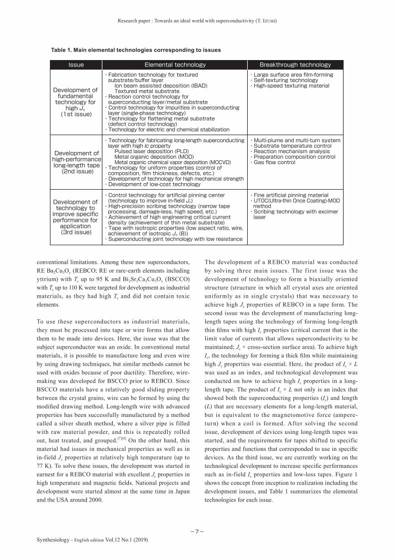
The development of a REBCO material was conducted by solving three main issues. The f irst issue was the development of technology to form a biaxially oriented structure (structure in which all crystal axes are oriented uniformly as in single crystals) that was necessary to achieve high Jc properties of REBCO in a tape form. The second issue was the development of manufacturing long-length tapes using the technology of forming long-length thin films with high Ic properties (critical current that is the limit value of currents that allows superconductivity to be maintained; Jc × cross-section surface area). To achieve high Ic, the technology for forming a thick film while maintaining high Jc properties was essential. Here, the product of Ic × L was used as an index, and technological development was conducted on how to achieve high Ic properties in a long-length tape. The product of Ic × L not only is an index that showed both the superconducting properties (Ic) and length (L) that are necessary elements for a long-length material, but is equivalent to the magnetomotive force (ampere-turn) when a coil is formed. After solving the second issue, development of devices using long-length tapes was started, and the requirements for tapes shifted to specific properties and functions that corresponded to use in specific devices. As the third issue, we are currently working on the technological development to increase specific performances such as in-field Ic properties and low-loss tapes. Figure 1 shows the concept from inception to realization including the development issues, and Table 1 summarizes the elemental technologies for each issue.
Table 1. Main elemental technologies corresponding to issues
・Fine artificial pinning material・UTOC(Ultra-thin Once Coating)-MOD method・Scribing technology with excimer laser
・Control technology for artificial pinning center (technology to improve in-field Jc)・High-precision scribing technology (narrow tape processing, damage-less, high speed, etc.)・Achievement of high engineering critical current density (achievement of thin metal substrate)・Tape with isotropic properties (low aspect ratio, wire, achievement of isotropic Jc (B))・Superconducting joint technology with low resistance
Development of technology to improve specific performance for application (3rd issue)
・Multi-plume and multi-turn system・Substrate temperature control・Reaction mechanism analysis・Preparation composition control・Gas flow control
・Technology for fabricating long-length superconducting layer with high Ic property Pulsed laser deposition (PLD) Metal organic deposition (MOD) Metal organic chemical vapor deposition (MOCVD)・Technology for uniform properties (control of composition, film thickness, defects, etc.)・Development of technology for high mechanical strength・Development of low-cost technology
Development of high-performance long-length tape (2nd issue)
・Large surface area film-forming・Self-texturing technology・High-speed texturing material
・Fabrication technology for textured substrate/buffer layer Ion beam assisted deposition (IBAD) Textured metal substrate・Reaction control technology for superconducting layer/metal substrate・Control technology for impurities in superconducting layer (single-phase technology)・Technology for flattening metal substrate (defect control technology)・Technology for electric and chemical stabilization
Development of fundamental technology for high Jc (1st issue)
Issue Elemental technology Breakthrough technology

Research paper : Towards an ideal world with superconductivity (T. IZUMI)
−8−
Synthesiology - English edition Vol.12 No.1 (2019)
In this paper, we outline the R&D conducted to solve each of the aforementioned issues through the selection of key technologies listed as the elemental technologies in Table 1. Here, the results of development at the International Superconductivity Technology Center (ISTEC) at which the author conducted research and AIST with which the author is currently affi liated will be featured. ISTEC was established in 1988 after the discovery of the aforementioned high-temperature superconductor. It is an incorporated foundation whose purpose was the promotion of R&D for high-temperature superconductors and their dissemination through activities such as organizing academic conferences. ISTEC was a joint industry-academia-government research center consisting of affiliated researchers, researchers dispatched from private companies, and foreign researchers from abroad. It operated for about 30 years until it was dissolved in 2016, and during its operation, it received subcontracts for several national projects from the Ministry of Economy, Trade and Industry (METI) and the New Energy and Industrial Technology Development Organization (NEDO). It formed joint research units with several private companies, universities, and national research institutes, to lead the world in the development of high-temperature superconductor technology. The strategy shown in Fig. 1 was created mainly by ISTEC, and was later shared in the world.
Representative national projects include, in chronological order: “R&D Project for Core Technology of Superconductivity Application” Phase I and Phase II, “Technological Development of Yttrium Superconducting Electric Devices,” “Technological Development of Yttrium Superconducting Electric Device (Joint Core Technology Development),” and others. These projects were subcontracted by METI, NEDO and the Japan Agency for Medical Research and Development (AMED). The early efforts centered on the development of tapes, and the latter shifted toward development of devices. ISTEC
took lead in forming the joint research units with companies, universities, and national research institutes, and then executed the developmental projects. It has become part of AIST and participates in the “Technological Development to Promote Practical Use of High-Temperature Superconductivity,” and continues the technological development to advance tape materials.
2 First issue (Development of high Jc core technology)
REBCO has the potential of having excellent Jc properties, but it is also known to be greatly dependent on the orientation of the crystal grains (the direction in which the crystals are arranged). Therefore, the first major issue was how to achieve biaxial orientation in tape formation, and various approaches were taken to realize this. First, wire-making was done using the silver sheath method that was successful for BSCCO material. Although it was possible to achieve a wire form using this method, it was diffi cult to achieve biaxially orientated crystal grains, and due to cracks and other issues, the best we could do was a low Jc property of 103 A/cm2
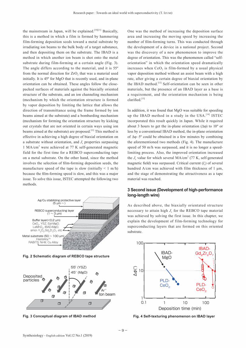
achieved in a self-generated magnetic fi eld (a magnetic fi eld generated by running current through linearly arranged wires) in liquid nitrogen (77 K).[9] In practice, it is thought that a Jc property of at least 105 A/cm2 (77 K, self-generated magnetic field) is necessary, and dramatic improvement was necessary. Later, several methods that enabled biaxial orientation was developed and this led to dramatic improvement of the properties. In a layered structure (Fig. 2) in which a number of intermediate layers were added to the metal substrate, these methods realized biaxial orientation by intermediate layers made by a special fi lm-forming method or special treatment of the metal substrate. In this paper, the ion beam assisted deposition (IBAD) method, which has been used most widely around the world and is becoming
Fig. 1 Concept of REBCO tape material
Development of technology to improve specific performance for application (3rd issue)
Development of high-performance long-length tape (2nd issue)
Development of fundamental technology for high Jc(1st issue)
Practical use
Development for application
Self-orientationCeO2
IBAD-MgO
SMES
Marine motor Accelerator
Transformer
Power cableAircraft
Research paper : Towards an ideal world with superconductivity (T. IZUMI)
−9−Synthesiology - English edition Vol.12 No.1 (2019)
the mainstream in Japan, will be explained.[10][11] Basically, this is a method in which a film is formed by hammering film-forming deposition seeds toward a metal substrate by irradiating ion beams to the bulk body of a target substance, and then depositing them on the substrate. The IBAD is a method in which another ion beam is shot onto the metal substrate during film-forming at a certain angle (Fig. 3). The angle differs according to the material, and it is 55º from the normal direction for ZrO2 that was a material used initially. It is 45º for MgO that is recently used, and in-plane orientation can be obtained. These angles follow the close-packed surfaces of materials against the biaxially oriented structure of the substrate, and an ion channeling mechanism (mechanism by which the orientation structure is formed by vapor deposition by limiting the lattice that allows the direction of transmittance using the frame formed by ion beams aimed at the substrate) and a bombarding mechanism (mechanism for forming the orientation structure by kicking out crystals that are not oriented in certain ways using ion beams aimed at the substrate) are proposed.[11] This method is effective in achieving a high degree of biaxial orientation on a substrate without orientation, and Jc properties surpassing 1 MA/cm2 were achieved at 77 K self-generated magnetic field for the first time for a REBCO superconducting tape on a metal substrate. On the other hand, since the method involves the selection of fi lm-forming deposition seeds, the manufacture speed of the tape is slow (initially < 1 m/h) because the fi lm-forming speed is slow, and this was a major issue. To solve this issue, ISTEC attempted the following two methods.
One was the method of increasing the deposition surface area and increasing the moving speed by increasing the number of fi lm-forming turns. This was conducted through the development of a device in a national project. Second was the discovery of a new phenomenon to improve the degree of orientation. This was the phenomenon called “self-orientation” in which the orientation speed dramatically increases when CeO2 is film-formed by a usual physical vapor deposition method without an assist beam with a high rate, after giving a certain degree of biaxial orientation by the IBAD method.[12] Self-orientation can be seen in other materials, but the presence of an IBAD layer as a base is a requirement, and the orientation mechanism is being clarifi ed.[13]
In addition, it was found that MgO was suitable for speeding up the IBAD method in a study in the USA.[14] ISTEC incorporated this result quickly in Japan. While it required about 3 hours to get the in-plane orientation (Δφ) to 10º or less by a conventional IBAD method, the in-plane orientation of Δφ–5º could be obtained in a few minutes by combining the aforementioned two methods (Fig. 4). The manufacture speed of 50 m/h was surpassed, and it is no longer a speed-limiting process. Also, the improved orientation increased the Jc value for which several MA/cm2 (77 K, self-generated magnetic fi eld) was surpassed. Critical current (Ic) of several hundred A/cm was achieved with film thickness of 1 μm, and the stage of demonstrating the attractiveness as a tape material was reached.
3 Second issue (Development of high-performance long-length wire)
As described above, the biaxially orientated structure necessary to attain high Jc for the REBCO tape material was achieved by solving the first issue. In this chapter, we explain the development of film-forming technology for superconducting layers that are formed on this oriented substrate.
Fig. 2 Schematic diagram of REBCO tape structure
Buffer layers(< 0.2 µm)
Metallic substrate (50~100 µm)HastelloyTR
RABiTS :Ni-W, Cu Alloy
Ag /Cu stabilizing &protection layer (5µm ~)
REBCO superconducting layer(1 ~ 3 µm)
CeO2, YSZ, Epi-MgO, LaMnO3,IBAD-MgO, amor.-Y2O3 ,Gd2Zr2O7 ,etc
REBCO superconducting layer(1~3 µm)
Ag/Cu stabilizing protective layer(5 µm~ )
Metal substrate (50~100 µm)HastelloyTR
RABiTS: Ni-W, Cu Alloy
Buffer layer(<0.2 µm)CeO2, YSZ, Epi-MgO, LaMnO3, IBAD-MgO, amor.-Y2O3,Gd2Zr2O7, etc
55° (YSZ)45° (MgO)
Ar +
Ion beam
Deposited particles
Deposition time (min)0.1 1 10 100
100
10
1
IBAD-MgO
PLD-CeO2
Gd2Zr2O7
PLD-CeO2
IBAD-
Δφ(°)
Fig. 3 Conceptual diagram of IBAD method Fig. 4 Self-texturing phenomenon on IBAD layer
Research paper : Towards an ideal world with superconductivity (T. IZUMI)
−10−
Synthesiology - English edition Vol.12 No.1 (2019)
The technologies to form the superconducting layers are roughly divided into gas phase methods and liquid phase methods. The gas phase methods include pulsed laser deposition (PLD) and metal organic chemical vapor deposition (MOCVD), and a representative chemical liquid phase method is the metal organic deposition (MOD) method. At ISTEC (AIST), development was conducted by PLD and MOD methods using trifluoroacetate (TFA) as the raw material. The following is an account of the characteristics of the two methods and their major results.
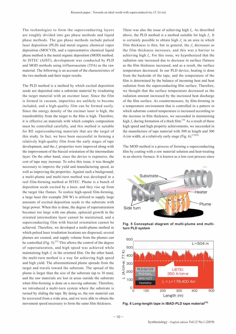
The PLD method is a method by which excited deposition seeds are deposited onto a substrate material by irradiating the target material with an excimer laser. Since the film is formed in vacuum, impurities are unlikely to become included, and a high-quality film can be formed easily. Since the energy density of the excimer laser is high, the transferability from the target to the fi lm is high. Therefore, it is effective on materials with which complex composition must be controlled carefully, and this method is suitable for RE superconducting materials that are the target of this study. In fact, we have been successful in forming a relatively high-quality film from the early stages of tape development, and the Jc properties were improved along with the improvement of the biaxial orientation of the intermediate layer. On the other hand, since the device is expensive, the cost of tape may increase. To solve this issue, it was thought necessary to improve the yield and manufacturing speed, as well as improving the properties. Against such a background, a multi-plume and multi-turn method was developed in a reel film-forming method at ISTEC. Plume is a bunch of deposition seeds excited by a laser, and they rise up from the target like flames. To realize high-speed film-forming, a large laser (for example 200 W) is utilized to supply large amounts of excited deposition seeds to the substrate with large power. When this is done, the degree of supersaturation becomes too large with one plume, epitaxial growth in the oriented intermediate layer cannot be maintained, and a superconducting film with biaxial orientation cannot be achieved. Therefore, we developed a multi-plume method in which pulsed laser irradiation locations are dispersed, several plumes are created, and supply volume from the plumes can be controlled (Fig. 5).[15] This allows the control of the degree of supersaturation, and high speed was achieved while maintaining high Jc in the oriented fi lm. On the other hand, the multi-turn method is a way for achieving high speed and high yield. The aforementioned plume spreads from the target and travels toward the substrate. The spread of the plume is larger than the size of the substrate (up to 10 mm), and the raw materials are lost in areas outside the substrate when fi lm-forming is done on a moving substrate. Therefore, we introduced a multi-turn system where the substrate is turned by sliding the tape. By doing so, the raw material can be recovered from a wide area, and we were able to obtain the movement speed necessary to form the same fi lm thickness.
There was also the issue of achieving high Ic. As described above, the PLD method is a method suitable for high Jc. It is certainly possible to obtain high Jc in an area in which film thickness is thin, but in general, the Jc decreases as the f ilm thickness increases, and this was a barrier to achieving high Ic. For this issue, we hypothesized that the radiation rate increased due to decrease in surface flatness as the fi lm thickness increased, and as a result, the surface temperature decreased. In our PLD device, heating is done from the backside of the tape, and the temperature of the fi lm is determined by the balance of incoming heat and heat radiation from the superconducting fi lm surface. Therefore, we thought that the surface temperature decreased as the radiation amount increased by the increased heat discharge of the fi lm surface. As countermeasure, by fi lm-forming in a temperature environment that is controlled in a pattern in which substrate control temperature is increased according to the increase in fi lm thickness, we succeeded in maintaining high Jc during formation of a thick fi lm.[16] As a result of these high speed and high property achievements, we succeeded in the manufacture of tape material with 500 m length and 300 A/cm width, at a relatively early stage (Fig. 6).[17][18]
The MOD method is a process of forming a superconducting fi lm by coating with a raw material solution and heat-treating in an electric furnace. It is known as a low-cost process since
Fig. 5 Conceptual diagram of multi-plume and multi-turn PLD system
Side turn
Heater
Plume
Substrate
Hastelloy ?
IBAD-GZOPLD-CeO2
PLD-Gd123
600
500
400
300
200
100
05004003002001000
Length (m)
L=504 m
Ic × L=176,400 Am
Ic(ETE):350 A/cm-w
Hastelloy
IBAD-GZO
PLD-CeO2
PLD-Gd123
(A/cm-w, 77 K)
I c
Fig. 6 Long-length tape in IBAD-PLD tape material[18]

Research paper : Towards an ideal world with superconductivity (T. IZUMI)
−11−Synthesiology - English edition Vol.12 No.1 (2019)
it does not require an expensive vacuum chamber or a heat source. However, in a general MOD method, the reaction is determined by pyrolysis, and epitaxial growth is difficult to obtain if there is no temperature difference in the film, and it was unsuitable for a REBCO superconducting film that was our target. However, large progress was made as epitaxial growth was made possible by using BaF2 as an intermediate product while using TFA as a raw material.[19] For the formation of superconducting layer in this system, as shown in Equation (1), it is necessary to supply water to BaF2 and have them react.
Y2Cu2O5 (s) + 2BaF2 (s) + 2CuO(s) + 2H2O(g)2 1
O2(g)2xYBa2Cu3O6.5+x(s) + 4HF (g) +→
… Equation (1)
In this reaction, HF gas is generated as a reaction product (Fig. 7). This conversion reaction enables epitaxial growth. We first analyzed the reaction mechanism, and found that the growth rate is determined by the exhaust speed of HF gas (Vg) and steam partial pressure (PH2O) and total pressure (Pt) and others.[20]
Pt PH2OVg
∝R… Equation (2)
In this method, improvement of Ic was an important issue, and technological development was aggressively pursued. A representative method is to achieve high properties by controlling the starting composition. In the MOD method, it was initially diff icult to achieve complete reaction during epitaxial growth, and the intermediate products (Y2Cu2O5, BaF2, CuO, etc.) were often incorporated into the superconducting layers. In that case, while Y2Cu2O5 and CuO became spherical and seldom became current inhibiting factors, Ba compounds tended to be present in the grain boundary, easily deteriorated, and were thought to cause the deterioration of properties. Therefore, we succeeded in achieving stable high properties by changing the starting composition to Ba deficient.[21] Also, in the MOD method, the
property surface does not change greatly since the reaction progresses from the bottom of the calcinated film that is used as the precursor, there is no temperature change by thickness as seen in the PDL film, and the decrease of Jc is not likely to occur against the film thickness. Therefore, we were able to achieve high Ic by thickening the film.[22]
For achieving long length, development was conducted by two major processes. One was a method called a reel-to-reel (RTR) method in which the tape with precursor film supplied from a reel is fed into an electric furnace to undergo heat treatment. This method allows stable reaction control as soon as a certain steady state is established, and therefore is a method suitable for stabilizing the long-length properties. However, there is an issue of manufacturing speed. The other is the batch method. This is a method where the precursor film is rolled onto a drum and heat-treated inside a large furnace. While it has excellent manufacturing speed, the issue is how to reduce the location dependency of the growth environment (temperature, gas flow, etc.). Both methods were optimized by controlling the temperature pattern and gas flow based on the basic investigations described above, and we succeeded in manufacturing a high-property long-length tape as shown in Fig. 8.[18][23]
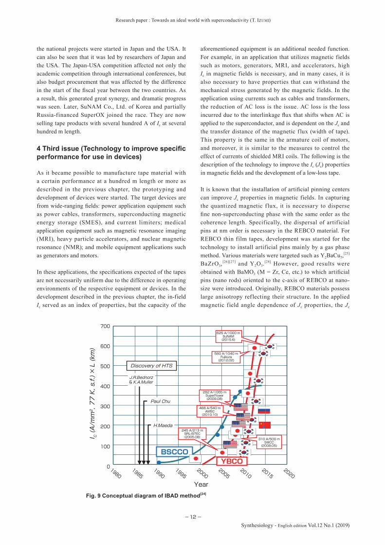
The long-length tape was achieved through joint development by ISTEC and tape manufacturers. The PLD method was a joint research mainly with Fujikura Ltd., and the TFA-MOD method was developed with SWCC Showa Cable Systems Co., Ltd. The results were obtained in the NEDO projects. On the other hand, a large-scale national project was done to develop tapes in the USA, and as a result, Japan and USA became leaders in the development of RE superconducting tapes. Here, development was conducted by setting as index the product of Ic × L that shows both the properties and length at the same time. Figure 9 shows the change in the Ic × L product.[24] Rapid progress was seen at around 2000 when
Substrate
Precursor
GrowthBaF2
HF
HF
Y2Cu2O5 CuO
H2O
H2O
Superconducting layer
Treatment speed: 22 m/h
5004003002001000
500
400
300
200
100
0
77 K, self fields
Length (m)
(A/cm-w)
I c
Fig. 7 Conceptual diagram showing reaction in TFA-MOD method Fig. 8 Long-length tape in IBAD-MOD tape material[18]
Research paper : Towards an ideal world with superconductivity (T. IZUMI)
−12−
Synthesiology - English edition Vol.12 No.1 (2019)
the national projects were started in Japan and the USA. It can also be seen that it was led by researchers of Japan and the USA. The Japan-USA competition affected not only the academic competition through international conferences, but also budget procurement that was affected by the difference in the start of the fi scal year between the two countries. As a result, this generated great synergy, and dramatic progress was seen. Later, SuNAM Co., Ltd. of Korea and partially Russia-financed SuperOX joined the race. They are now selling tape products with several hundred A of Ic at several hundred m length.
4 Third issue (Technology to improve specifi c performance for use in devices)
As it became possible to manufacture tape material with a certain performance at a hundred m length or more as described in the previous chapter, the prototyping and development of devices were started. The target devices are from wide-ranging fi elds: power application equipment such as power cables, transformers, superconducting magnetic energy storage (SMES), and current limiters; medical application equipment such as magnetic resonance imaging (MRI), heavy particle accelerators, and nuclear magnetic resonance (NMR); and mobile equipment applications such as generators and motors.
In these applications, the specifi cations expected of the tapes are not necessarily uniform due to the difference in operating environments of the respective equipment or devices. In the development described in the previous chapter, the in-field Ic served as an index of properties, but the capacity of the
aforementioned equipment is an additional needed function. For example, in an application that utilizes magnetic fields such as motors, generators, MRI, and accelerators, high Ic in magnetic fields is necessary, and in many cases, it is also necessary to have properties that can withstand the mechanical stress generated by the magnetic fields. In the application using currents such as cables and transformers, the reduction of AC loss is the issue. AC loss is the loss incurred due to the interlinkage fl ux that shifts when AC is applied to the superconductor, and is dependent on the Jc and the transfer distance of the magnetic f lux (width of tape). This property is the same in the armature coil of motors, and moreover, it is similar to the measures to control the effect of currents of shielded MRI coils. The following is the description of the technology to improve the Ic (Jc) properties in magnetic fi elds and the development of a low-loss tape.
It is known that the installation of artifi cial pinning centers can improve Jc properties in magnetic fields. In capturing the quantized magnetic f lux, it is necessary to disperse fi ne non-superconducting phase with the same order as the coherence length. Specifically, the dispersal of artificial pins at nm order is necessary in the REBCO material. For REBCO thin film tapes, development was started for the technology to install artificial pins mainly by a gas phase method. Various materials were targeted such as Y2BaCu5,
[25]
BaZrO3,[26][27] and Y2O3.
[28] However, good results were obtained with BaMO3 (M = Zr, Ce, etc.) to which artifi cial pins (nano rods) oriented to the c-axis of REBCO at nano-size were introduced. Originally, REBCO materials possess large anisotropy ref lecting their structure. In the applied magnetic field angle dependence of Jc properties, the Jc
I C (A/mm2, 77 K, s.f.) × L (km)
700
600
500
400
300
200
100
0
Discovery of HTS
J.R.Bednorz& K.A.Muller
H.Maeda
Paul Chu
245 A/213 mSRL-ISTEC(2005.08)
625 A/1000 mSuNAM(2015.6)
580 A/1040 mFujikura(2012.02)
282 A/1065 mSuperPower(2009.08)
466 A/540 mAMSC
(2010.10)
310 A/500 mSWCC
(2008.05)
Year
20202015
20102005
20001995
19901985
1980
YBCOBSCCO
Fig. 9 Conceptual diagram of IBAD method[24]
Research paper : Towards an ideal world with superconductivity (T. IZUMI)
−13−Synthesiology - English edition Vol.12 No.1 (2019)
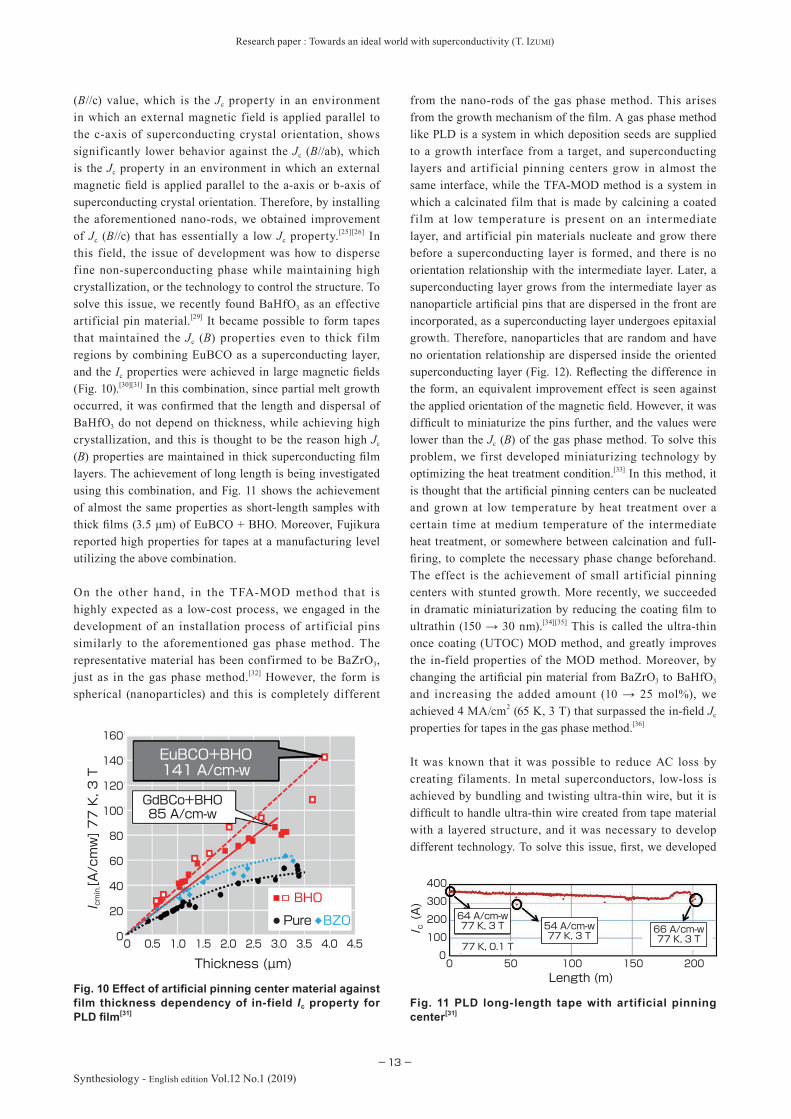
(B//c) value, which is the Jc property in an environment in which an external magnetic field is applied parallel to the c-axis of superconducting crystal orientation, shows significantly lower behavior against the Jc (B//ab), which is the Jc property in an environment in which an external magnetic fi eld is applied parallel to the a-axis or b-axis of superconducting crystal orientation. Therefore, by installing the aforementioned nano-rods, we obtained improvement of Jc (B//c) that has essentially a low Jc property.[25][26] In this field, the issue of development was how to disperse fine non-superconducting phase while maintaining high crystallization, or the technology to control the structure. To solve this issue, we recently found BaHfO3 as an effective artificial pin material.[29] It became possible to form tapes that maintained the Jc (B) properties even to thick film regions by combining EuBCO as a superconducting layer, and the Ic properties were achieved in large magnetic fi elds (Fig. 10).[30][31] In this combination, since partial melt growth occurred, it was confi rmed that the length and dispersal of BaHfO3 do not depend on thickness, while achieving high crystallization, and this is thought to be the reason high Jc
(B) properties are maintained in thick superconducting fi lm layers. The achievement of long length is being investigated using this combination, and Fig. 11 shows the achievement of almost the same properties as short-length samples with thick fi lms (3.5 μm) of EuBCO + BHO. Moreover, Fujikura reported high properties for tapes at a manufacturing level utilizing the above combination.
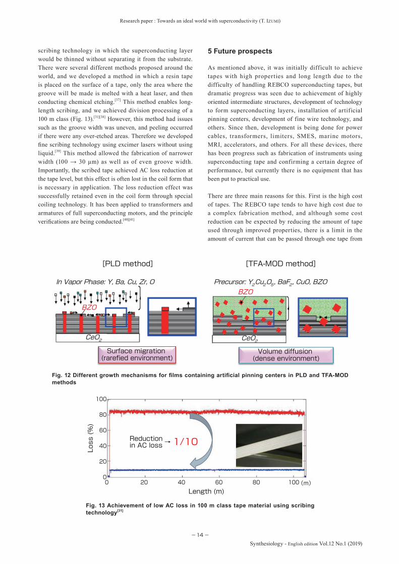
On the other hand, in the TFA-MOD method that is highly expected as a low-cost process, we engaged in the development of an installation process of artificial pins similarly to the aforementioned gas phase method. The representative material has been confirmed to be BaZrO3, just as in the gas phase method.[32] However, the form is spherical (nanoparticles) and this is completely different
from the nano-rods of the gas phase method. This arises from the growth mechanism of the fi lm. A gas phase method like PLD is a system in which deposition seeds are supplied to a growth interface from a target, and superconducting layers and artificial pinning centers grow in almost the same interface, while the TFA-MOD method is a system in which a calcinated film that is made by calcining a coated f ilm at low temperature is present on an intermediate layer, and artificial pin materials nucleate and grow there before a superconducting layer is formed, and there is no orientation relationship with the intermediate layer. Later, a superconducting layer grows from the intermediate layer as nanoparticle artifi cial pins that are dispersed in the front are incorporated, as a superconducting layer undergoes epitaxial growth. Therefore, nanoparticles that are random and have no orientation relationship are dispersed inside the oriented superconducting layer (Fig. 12). Refl ecting the difference in the form, an equivalent improvement effect is seen against the applied orientation of the magnetic fi eld. However, it was diffi cult to miniaturize the pins further, and the values were lower than the Jc (B) of the gas phase method. To solve this problem, we first developed miniaturizing technology by optimizing the heat treatment condition.[33] In this method, it is thought that the artifi cial pinning centers can be nucleated and grown at low temperature by heat treatment over a certain time at medium temperature of the intermediate heat treatment, or somewhere between calcination and full-fi ring, to complete the necessary phase change beforehand. The effect is the achievement of small artificial pinning centers with stunted growth. More recently, we succeeded in dramatic miniaturization by reducing the coating fi lm to ultrathin (150 → 30 nm).[34][35] This is called the ultra-thin once coating (UTOC) MOD method, and greatly improves the in-field properties of the MOD method. Moreover, by changing the artifi cial pin material from BaZrO3 to BaHfO3
and increasing the added amount (10 → 25 mol%), we achieved 4 MA/cm2 (65 K, 3 T) that surpassed the in-fi eld Jc
properties for tapes in the gas phase method.[36]
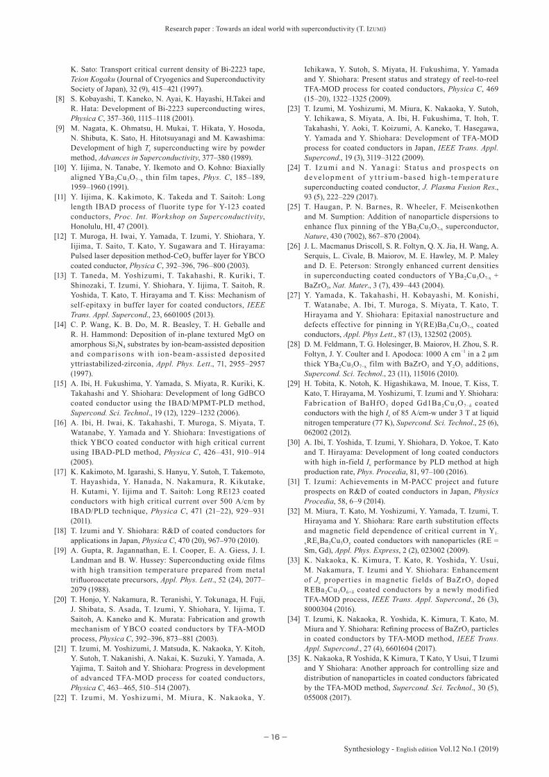
It was known that it was possible to reduce AC loss by creating filaments. In metal superconductors, low-loss is achieved by bundling and twisting ultra-thin wire, but it is diffi cult to handle ultra-thin wire created from tape material with a layered structure, and it was necessary to develop different technology. To solve this issue, fi rst, we developed
Thickness (µm)
BZOPure
BHO
EuBCO+BHO141 A/cm-w
GdBCo+BHO85 A/cm-w
0
20
40
60
80
100
120
140
160
4.54.03.53.02.52.01.51.00.50
I cmin.[A/cmw] 77 K, 3 T
0 100 20050 1500
100
200
300
400
Length (m)
(A)
I c
64 A/cm-w77 K, 3 T 54 A/cm-w
77 K, 3 T66 A/cm-w77 K, 3 T
77 K, 0.1 T
Fig. 10 Effect of artifi cial pinning center material against film thickness dependency of in-field Ic property for PLD fi lm[31]
Fig. 11 PLD long-length tape with artificial pinning center[31]
Research paper : Towards an ideal world with superconductivity (T. IZUMI)
−14−
Synthesiology - English edition Vol.12 No.1 (2019)
1/10
Length (m)
Loss (%)
(m)100806040200
100
80
60
40
20
0
→Reduction in AC loss
Fig. 13 Achievement of low AC loss in 100 m class tape material using scribing technology[31]
scribing technology in which the superconducting layer would be thinned without separating it from the substrate. There were several different methods proposed around the world, and we developed a method in which a resin tape is placed on the surface of a tape, only the area where the groove will be made is melted with a heat laser, and then conducting chemical etching.[37] This method enables long-length scribing, and we achieved division processing of a 100 m class (Fig. 13).[31][38] However, this method had issues such as the groove width was uneven, and peeling occurred if there were any over-etched areas. Therefore we developed fi ne scribing technology using excimer lasers without using liquid.[39] This method allowed the fabrication of narrower width (100 → 30 μm) as well as of even groove width. Importantly, the scribed tape achieved AC loss reduction at the tape level, but this effect is often lost in the coil form that is necessary in application. The loss reduction effect was successfully retained even in the coil form through special coiling technology. It has been applied to transformers and armatures of full superconducting motors, and the principle verifi cations are being conducted.[40][41]
5 Future prospects
As mentioned above, it was initially difficult to achieve tapes with high properties and long length due to the difficulty of handling REBCO superconducting tapes, but dramatic progress was seen due to achievement of highly oriented intermediate structures, development of technology to form superconducting layers, installation of artificial pinning centers, development of fine wire technology, and others. Since then, development is being done for power cables, transformers, limiters, SMES, marine motors, MRI, accelerators, and others. For all these devices, there has been progress such as fabrication of instruments using superconducting tape and confirming a certain degree of performance, but currently there is no equipment that has been put to practical use.
There are three main reasons for this. First is the high cost of tapes. The REBCO tape tends to have high cost due to a complex fabrication method, and although some cost reduction can be expected by reducing the amount of tape used through improved properties, there is a limit in the amount of current that can be passed through one tape from
[TFA-MOD method][PLD method]
BZO
CeO2
Precursor: Y2Cu2O5, BaF2, CuO, BZO
CeO2
BZOIn Vapor Phase: Y, Ba, Cu, Zr, O
Volume diffusion (dense environment)
Surface migration (rarefied environment)
Fig. 12 Different growth mechanisms for fi lms containing artifi cial pinning centers in PLD and TFA-MOD methods
Research paper : Towards an ideal world with superconductivity (T. IZUMI)
−15−Synthesiology - English edition Vol.12 No.1 (2019)
the perspective of energy recovery and protection. In general, 700–800 A/cm range is the limit as the operating current, and considering the load factor, 1300–1500 A/cm range is the maximum critical current. Therefore, if this critical current is not reached in the environment of operating temperature and magnetic field for each equipment, essential cost reduction can be achieved by improving the operating current. Currently, the above properties are already satisfied at 50 K or less with 1–2 T of external magnetic fields, but further development is needed for expected high temperature (e.g. liquid nitrogen temperature 65–77 K) and medium to high magnetic fields (3 T or more).
Another cause of high cost is the low yield. To truly increase the yield, it is necessary to improve the uniformity, but it is not easy to fabricate a narrow tape in km order without any areas of property degradation. Therefore, it is necessary to establish repair technology that enables recovery and increases stability.
The second reason why a superconducting device has not reached practical application is that there is no established overwhelming superiority against the existing technology. Although there is much equipment for which functions have been verified, a user will select the existing technology backed with past good results unless the new technology is absolute. There needs to be something that can only be realized with superconducting devices. For example, although there is no great superiority of a device itself, clear superiority may be seen when by using the superconducting device, a building can be kept very small and there is overwhelming cost merit in doing so. Such superiority is necessary in the initial introduction of this new technology.
The third important factor is the level of commitment of the end user. Of course, this links to the first two reasons, and along with overwhelming superiority, the user must be committed to participating in the development of a technology that will become necessary in the present or near future. The REBCO superconducting tape discussed in this paper has great attractiveness due to many advantages, but also has several disadvantages. A representative disadvantage is low handling due to it being a tape. Compared to wires, it lacks malleability and it is difficult to be arranged in coils or complex shapes. As a measure, the technology to form wire has been attempted, but this is not easy in terms of maintaining uniformity. Therefore, when conducting device development under certain limitations, it is necessary to consider the structure and operation that can be accomplished uniquely with a superconductor tape, rather than simply replacing metal wire.
Development is being conducted by many engineers around the world, but progress is slow at this point. The author thinks that one of the applications that may provide a breakthrough
is the application to electric propulsion aircraft. To respond to the requirement for CO2 reduction, the aviation industry is trying to shift from jet propulsion to electric propulsion. However, if one tries to achieve motorization by normal conductivity (iron and copper), the medium to large aircraft will become extremely heavy, and that is disadvantageous for aircraft. Therefore, an electric propulsion system using superconductor technology is expected. This is an idea of building a lightweight and high-output propulsion system using superconductors with full superconducting generators, motors, cables, and others. Since aircraft itself is expensive, the cost ratio of the tape will be small, and the tape cost may cease to be a problem. Since large aircraft is difficult unless superconductors are used, it is likely to be a major candidate if the user sets his mind on such development.
Overviewing the current situation, the high-temperature superconductivity technology is thought to be in the “valley of death” that is often encountered by new technology. To break out of this situation, it is necessary to achieve the first practical application by solving the aforementioned issues. For the superconductor technology to diffuse widely, it is important to show the effectiveness of this technology to the world through practical application.
Acknowledgement
Parts of the results described in this paper were achieved through the financial support of: the Ministry of Economy, Trade and Industry (METI); the New Energy and Industrial Technology Development Organization (NEDO); and the Japan Agency for Medical Research and Development (AMED).
References
[1] H. K. Onnes: The superconductivity of mercury, Comm. Phys. Lab. Univ. Leiden, 122, 124 (1911).
[2] J. G. Bednorz and K. A. Mul ler : Possible h igh Tc superconductivity in the Ba−La−Cu−O system, Z. Phys. B, 64, 189–193 (1986).
[3] H. Takagi, S. Uchida, H. Obara, K. Kishio, K. Kitazawa, K. Fueki and S. Tanaka: Magnetic susceptibility of high-Tc superconducting oxides (La, A)2CuO4 (A=Ba, Sr), Jpn. J. Appl. Phys., 26 (4), L434–L436 (1987).
[4] M. K. Wu, J. R. Ashburn, C. J. Torng, P. H. Hor, R. L. Meng, L. Gao, Z. J. Huang, Y. Q. Wang and C. W. Chu: Superconductivity at 93 K in a new mixed-phase Y-Ba-Cu-O compound system at ambient pressure, Phys. Rev. Lett., 58 (9), 908–910 (1987).
[5] H. Maeda, Y. Tanaka, M. Fukutomi and T. Asano: A new high-Tc oxide superconductor without a rare earth element, Jpn. J. Appl. Phys., 27, L209–L210 (1988).
[6] L. Gao, Z. J. Huang, R. L. Meng, P. H. Hor, J. Bechtold, Y. Y. Sun, C. W. Chu, Z. Z. Sheng and A. M. Hermann: Bulk superconductivity in Tl2CaBa2Cu2O8+δ up to 120 K, Nature, 332, 623–624 (1988).
[7] S. Kobayashi, T. Kaneko, M. Umeyama, K. Hayashi and
Research paper : Towards an ideal world with superconductivity (T. IZUMI)
−16−
Synthesiology - English edition Vol.12 No.1 (2019)
K. Sato: Transport critical current density of Bi-2223 tape, Teion Kogaku (Journal of Cryogenics and Superconductivity Society of Japan), 32 (9), 415–421 (1997).
[8] S. Kobayashi, T. Kaneko, N. Ayai, K. Hayashi, H.Takei and R. Hata: Development of Bi-2223 superconducting wires, Physica C, 357–360, 1115–1118 (2001).
[9] M. Nagata, K. Ohmatsu, H. Mukai, T. Hikata, Y. Hosoda, N. Shibuta, K. Sato, H. Hitotsuyanagi and M. Kawashima: Development of high Tc superconducting wire by powder method, Advances in Superconductivity, 377–380 (1989).
[10] Y. Iijima, N. Tanabe, Y. Ikemoto and O. Kohno: Biaxially aligned YBa2Cu3O7−x thin film tapes, Phys. C, 185–189, 1959–1960 (1991).
[11] Y. Iijima, K. Kakimoto, K. Takeda and T. Saitoh: Long length IBAD process of f luorite type for Y-123 coated conductors, Proc. Int. Workshop on Superconductivity, Honolulu, HI, 47 (2001).
[12] T. Muroga, H. Iwai, Y. Yamada, T. Izumi, Y. Shiohara, Y. Iijima, T. Saito, T. Kato, Y. Sugawara and T. Hirayama: Pulsed laser deposition method-CeO2 buffer layer for YBCO coated conductor, Physica C, 392–396, 796–800 (2003).
[13] T. Taneda, M. Yoshizumi, T. Takahashi, R. Kuriki, T. Shinozaki, T. Izumi, Y. Shiohara, Y. Iijima, T. Saitoh, R. Yoshida, T. Kato, T. Hirayama and T. Kiss: Mechanism of self-epitaxy in buffer layer for coated conductors, IEEE Trans. Appl. Supercond., 23, 6601005 (2013).
[14] C. P. Wang, K. B. Do, M. R. Beasley, T. H. Geballe and R. H. Hammond: Deposition of in-plane textured MgO on amorphous Si3N4 substrates by ion-beam-assisted deposition and compar isons with ion-beam-assisted deposited yttriastabilized-zirconia, Appl. Phys. Lett., 71, 2955–2957 (1997).
[15] A. Ibi, H. Fukushima, Y. Yamada, S. Miyata, R. Kuriki, K. Takahashi and Y. Shiohara: Development of long GdBCO coated conductor using the IBAD/MPMT-PLD method, Supercond. Sci. Technol., 19 (12), 1229–1232 (2006).
[16] A. Ibi, H. Iwai, K. Takahashi, T. Muroga, S. Miyata, T. Watanabe, Y. Yamada and Y. Shiohara: Investigations of thick YBCO coated conductor with high critical current using IBAD-PLD method, Physica C, 426–431, 910–914 (2005).
[17] K. Kakimoto, M. Igarashi, S. Hanyu, Y. Sutoh, T. Takemoto, T. Hayashida, Y. Hanada, N. Nakamura, R. Kikutake, H. Kutami, Y. Iijima and T. Saitoh: Long RE123 coated conductors with high critical current over 500 A/cm by IBAD/PLD technique, Physica C, 471 (21–22), 929–931 (2011).
[18] T. Izumi and Y. Shiohara: R&D of coated conductors for applications in Japan, Physica C, 470 (20), 967–970 (2010).
[19] A. Gupta, R. Jagannathan, E. I. Cooper, E. A. Giess, J. I. Landman and B. W. Hussey: Superconducting oxide films with high transition temperature prepared from metal trifluoroacetate precursors, Appl. Phys. Lett., 52 (24), 2077–2079 (1988).
[20] T. Honjo, Y. Nakamura, R. Teranishi, Y. Tokunaga, H. Fuji, J. Shibata, S. Asada, T. Izumi, Y. Shiohara, Y. Iijima, T. Saitoh, A. Kaneko and K. Murata: Fabrication and growth mechanism of YBCO coated conductors by TFA-MOD process, Physica C, 392–396, 873–881 (2003).
[21] T. Izumi, M. Yoshizumi, J. Matsuda, K. Nakaoka, Y. Kitoh, Y. Sutoh, T. Nakanishi, A. Nakai, K. Suzuki, Y. Yamada, A. Yajima, T. Saitoh and Y. Shiohara: Progress in development of advanced TFA-MOD process for coated conductors, Physica C, 463–465, 510–514 (2007).
[22] T. Izumi, M. Yoshizumi, M. Miura, K. Nakaoka, Y.
Ichikawa, Y. Sutoh, S. Miyata, H. Fukushima, Y. Yamada and Y. Shiohara: Present status and strategy of reel-to-reel TFA-MOD process for coated conductors, Physica C, 469 (15–20), 1322–1325 (2009).
[23] T. Izumi, M. Yoshizumi, M. Miura, K. Nakaoka, Y. Sutoh, Y. Ichikawa, S. Miyata, A. Ibi, H. Fukushima, T. Itoh, T. Takahashi, Y. Aoki, T. Koizumi, A. Kaneko, T. Hasegawa, Y. Yamada and Y. Shiohara: Development of TFA-MOD process for coated conductors in Japan, IEEE Trans. Appl. Supercond., 19 (3), 3119–3122 (2009).
[24] T. I z u mi and N. Yanag i: St at us and prospect s on developme nt of y t t r iu m-ba sed h ig h - t empe r a t u re superconducting coated conductor, J. Plasma Fusion Res., 93 (5), 222–229 (2017).
[25] T. Haugan, P. N. Barnes, R. Wheeler, F. Meisenkothen and M. Sumption: Addition of nanoparticle dispersions to enhance flux pinning of the YBa2Cu3O7-x superconductor, Nature, 430 (7002), 867–870 (2004).
[26] J. L. Macmanus Driscoll, S. R. Foltyn, Q. X. Jia, H. Wang, A. Serquis, L. Civale, B. Maiorov, M. E. Hawley, M. P. Maley and D. E. Peterson: Strongly enhanced current densities in superconducting coated conductors of YBa2Cu3O7-x + BaZrO3, Nat. Mater., 3 (7), 439–443 (2004).
[27] Y. Yamada, K. Takahashi, H. Kobayashi, M. Konishi, T. Watanabe, A. Ibi, T. Muroga, S. Miyata, T. Kato, T. Hirayama and Y. Shiohara: Epitaxial nanostructure and defects effective for pinning in Y(RE)Ba2Cu3O7-x coated conductors, Appl. Phys Lett., 87 (13), 132502 (2005).
[28] D. M. Feldmann, T. G. Holesinger, B. Maiorov, H. Zhou, S. R. Foltyn, J. Y. Coulter and I. Apodoca: 1000 A cm−1 in a 2 μm thick YBa2Cu3O7−x film with BaZrO3 and Y2O3 additions, Supercond. Sci. Technol., 23 (11), 115016 (2010).
[29] H. Tobita, K. Notoh, K. Higashikawa, M. Inoue, T. Kiss, T. Kato, T. Hirayama, M. Yoshizumi, T. Izumi and Y. Shiohara: Fabrication of BaHfO3 doped Gd1Ba2Cu3O7−δ coated conductors with the high Ic of 85 A/cm-w under 3 T at liquid nitrogen temperature (77 K), Supercond. Sci. Technol., 25 (6), 062002 (2012).
[30] A. Ibi, T. Yoshida, T. Izumi, Y. Shiohara, D. Yokoe, T. Kato and T. Hirayama: Development of long coated conductors with high in-field Ic performance by PLD method at high production rate, Phys. Procedia, 81, 97–100 (2016).
[31] T. Izumi: Achievements in M-PACC project and future prospects on R&D of coated conductors in Japan, Physics Procedia, 58, 6–9 (2014).
[32] M. Miura, T. Kato, M. Yoshizumi, Y. Yamada, T. Izumi, T. Hirayama and Y. Shiohara: Rare earth substitution effects and magnetic field dependence of critical current in Y1-
xRExBa2Cu3Oy coated conductors with nanoparticles (RE = Sm, Gd), Appl. Phys. Express, 2 (2), 023002 (2009).
[33] K. Nakaoka, K. Kimura, T. Kato, R. Yoshida, Y. Usui, M. Nakamura, T. Izumi and Y. Shiohara: Enhancement of Jc proper ties in magnetic f ields of BaZrO3 doped REBa2Cu3O6+δ coated conductors by a newly modified TFA-MOD process, IEEE Trans. Appl. Supercond., 26 (3), 8000304 (2016).
[34] T. Izumi, K. Nakaoka, R. Yoshida, K. Kimura, T. Kato, M. Miura and Y. Shiohara: Refining process of BaZrO3 particles in coated conductors by TFA-MOD method, IEEE Trans. Appl. Supercond., 27 (4), 6601604 (2017).
[35] K. Nakaoka, R Yoshida, K Kimura, T Kato, Y Usui, T Izumi and Y Shiohara: Another approach for controlling size and distribution of nanoparticles in coated conductors fabricated by the TFA-MOD method, Supercond. Sci. Technol., 30 (5), 055008 (2017).
Research paper : Towards an ideal world with superconductivity (T. IZUMI)
−17−Synthesiology - English edition Vol.12 No.1 (2019)
[36] M. Miura, B. Maiorov, M. Sato, M. Kanai, T. Kato, T. Kato, T. Izumi, S. Awaji, P. Mele, M. Kiuchi and T. Matsushita: Tuning nanoparticle size for enhanced functionality in perovskite thin fi lms deposited by metal organic deposition, NPG Asia Materials, 9, e447 (2017).
[37] T. Machi, K. Nakao, T. Kato, T. Hirayama and K. Tanabe: Reliable fabr icat ion process for long-length mult i-filamentary coated conductors by a laser scribing method for reduction of AC loss, Supercond. Sci. Technol., 26 (10), 105016 (2013).
[38] H. Okamoto, H. Hayashi, M. Iwakuma, A. Tomioka, T. Saito, Y. Gosho, K. Tanabe and Y. Shiohara: Over-current characteristics of model coil using Y-based multi-filament wire for superconducting power transformers, Physica C, 471 (21–22), 1379–1380 (2011).
[39] K. Katayama, T. Machi, T. Nakamura, Y. Takagi, K. Nakaoka, M. Yoshizumi, T. Izumi and Y. Shiohara: Development of low AC loss TFA-MOD coated conductors, Physics Procedia, 58, 142–145 (2014).
[40] M. Iwakuma, K. Sakaki, A. Tomioka, T. Miyayama, M. Konno, H. Hayashi, H. Okamoto, Y. Gosho, T. Eguchi, S. Yoshida, Y. Suzuki, H. Hirai, Y. Iijima, T. Saitoh, T. Izumi and Y. Shiohara: Development of a 3φ-66/6.9 kV-2 MVA REBCO superconducting transformer, IEEE Transactions on Applied Superconductivity, 25, 5500206 (2015).
[41] S. Fukuda, K. Yun, M. Iwakuma, S. Miura, S. Sato, K. Yoshida, A. Tomioka, M. Konno and T. Izumi: Design study of 2-MW fully superconducting synchronous motors, IEEE Transactions on Applied Superconductivity, 28 (4), 5207806 (2018).
Author
Teruo IZUMIGraduated from the Graduate School of Engineering, Tohoku University in March 1987. Doctor (Engineer ing). Joined the Sumitomo Metal Industries, Ltd. and was dispatched to International Superconductivity Technology Center (ISTEC) during 1989–1993. Joined ISTEC in 1998, and then joined AIST in 2016 upon dissolution of ISTEC. Consistently engaged in the development of magnet ic mater ials, oxide superconductor materials, and silicon monocrystal materials. Since 1998, engaged in the development of an RE superconductor tape process and its application, and was involved in many national projects. Acted as project leader. In this paper, described the development of RE superconductor tape material based on the experiences in these projects.
Discussions with Reviewers
1 OverallComment (Toshihiko Kanayama, AIST)Eve r s i nc e t he d i s c ove r y of h ig h - t e mp e r a t u r e ox id e superconductors in 1986, the development and pract ical application of wires and tapes using the material has been a technology of dreams that has not been realized, despite great expectations. This paper describes the issues and courses of development centering on the results obtained by the author, selection of materials and synthesis methods, practical fabrication
technology for long-length tapes, and technology to improve properties. It is also mentioned that national project research involving companies was effective in this process. It is necessary to integrate diverse elemental technologies to link a discovery of a new substance to practical products, and this is a signifi cant example that illustrates the necessity of continuous development over many years by a number of researchers.Comment (Kei’ichi Ikegami, AIST)
This paper is about the development of a rare-ear th superconducting tape material that is on the verge of practical realization, and that is expected for use in devices in the future. It explains the origin and the current situation comprehensively in an understandable manner, and it is well worth reading as a technological guidebook with a historical perspective.
2 R&D scenarioComment 1 (Kei’ichi Ikegami)
The “scenario” on which Synthesiology places much value is set by a certain subject, while in this paper, to emphasize objectivity, the presence of a subject or agent, who set the scenario and pushed the development, has become weak. As a Synthesiology paper, the paper should focus as its subject of analysis not on the superconducting material, but on case studies of development. Therefore, I think you should make additions to clarify the core agent of the case studies.
You present Fig. 1 as your scenario, but when I read this paper, I see that the R&D was conducted by three different scenarios for three issues at stake. On the other hand, Synthesiology states: “To describe the elemental technology (technologies) that was (were) selected to realize the research goal. To describe the reasons for selecting the elemental technology (technologies). To describe in the terminology of science and technology how the selected elements are interrelated to each other, and how the elements were integrated and synthesized to realize the research goal.” Therefore, in addition to Fig. 1, I think you should have a “fi gure for a detailed scenario” that shows how you selected the elemental technologies and how they were synthesized and integrated to realize the research goal.Comment 2 (Toshihiko Kanayama)
This paper describes the important points of a general descr ipt ion of the ch ronology of development of oxide superconducting tapes. However, it is not clear how the author or the institution to which the author belongs made selections that led up to the development, that is the main focus of Synthesiology.
To clarify this point, how about adding a table of elemental technologies? I think the signifi cance of this paper will be greatly enhanced if the reader can easily see what kinds of elemental technologies were candidates of the three issues shown in Fig. 1, and which ones the author or the institution selected.Answer (Teruo Izumi)
I summarized the elemental technologies for each issue in Table 1.Comment 3 (Toshihiko Kanayama)
The addition of Table 1 made the outline of the structure clearer. However, many of the elemental technologies remain as mere listings of technological issues that were targeted. For example, how about setting a third column with a title such as “Breakthrough technology” in correspondence to the elemental technologies of the second column? Then, I think the fl ow of the paper can be discerned easily if you describe the solutions that became keys to development of each elemental technology issue that is discussed in this paper.Answer (Teruo Izumi)
As you indicated above, I revised the table.

Research paper : Towards an ideal world with superconductivity (T. IZUMI)
−18−
Synthesiology - English edition Vol.12 No.1 (2019)
3 Core agent of R&DComment 1 (Kei’ichi Ikegami)
Figure 1 is shown as the scenar io, but who set th is scenario? It seems to be shared among the worldwide research community which was involved in the development of rare-earth superconductors, and it also seems to be the strategy employed by the research group at ISTEC (AIST) to which the author belongs. I think you should clarify the main agent of the development that you are analyzing at the beginning of the paper.Answer (Teruo Izumi)
The scenario in Fig. 1 can be called the strategy of ISTEC (AIST), and I added this fact to the text.
The main agent of the development was written clearly at the end of “1 Introduction.”Comment 2 (Toshihiko Kanayama)
Please write up separately the world trend of development and the items promoted by the author and the institution to which the author belongs.Answer (Teruo Izumi)
To clarify the items conducted by ISTEC (AIST), the subject “ISTEC” or “we” were added to the text.
4 R&D organization and national projectComment 1 (Kei’ichi Ikegami)
It can be seen that in the research analyzed in this paper, the organization called ISTEC seems to have played a very important role. Please describe how ISTEC came to be, its mission, positioning in the national strategy, leadership of this organization, how and which researchers were gathered, and how these researchers worked on R&D through their union, collaboration, and division of labor.Comment 2 (Toshihiko Kanayama)
This paper mentions that the national project research was effective, but it does not mention the content or the organizational structure. Please add some simple explanation about ISTEC and
the NEDO projects.Answer (Teruo Izumi)
I added a description of ISTEC at the end of “1 Introduction.”
5 International competitionComment (Kei’ichi Ikegami)
I think there was fierce competition of development against overseas teams, especially the Americans, and I am curious how this affected the scenario setting and execution. Can you add some text about this?Answer (Teruo Izumi)
For the effect of competition between Japan and USA as you mentioned, text was added to the end of “3 Second issue.”
6 R&D issues and required valuesComment 1 (Toshihiko Kanayama)The relationship between the achieved value and the required value for electric current that is described as the issue for practical realization in “Future prospects” is not clear. Please add some text on this matter. Also, I think the positioning of this paper will become clear if you add, if possible, the issues that remain toward practical realization and the candidate solutions.Answer (Teruo Izumi)
I added a text to “Future prospects.”Comment 2 (Kei’ichi Ikegami)
In “2 First issue,” you state, “obtaining a Jc property of about 103 A/cm2 (77 K, self-generated magnetic field) was the best we could do.” I don’t think the readers will understand the meaning of these numbers unless you indicate other numbers for comparison, such as how many Jc properties are needed for practical realization, or what level of Jc properties has been realized in tapes of other materials.Answer (Teruo Izumi)
I added explanations on the points indicated above.
Research paper
−19−Synthesiology - English edition Vol.12 No.1 pp.19–28 (Aug. 2019)
is a tool to realize the just-in-time production method that is the basic philosophy of Toyota. It is a specification sheet that is attached to the components and travels everywhere with them. As production volume increased, more invoices had to be processed, and more mistakes occurred as data input was done manually on the computer. Therefore, barcodes were introduced to the “kanban” along with the reader to read the codes to achieve automatic input to the computers. Denso realized the importance of information, was convinced that the information age would arrive with the diffusion of computers in the future, and developed several information input devices for computers. It started on the development of the QR code in 1992. At the time, barcodes were widely used as an accurate, fast, and low-cost input method in printed form.[1] However, the age in which anything could be sold after being manufactured ended with the burst of the economic bubble, and manufacturing trends shifted from mass production to “multiple product low volume” production.
The manufacturers started to conduct finely-tuned production control, and with the increase of information volume handled, about 10 different barcodes had to be read for management control at manufacturing plants. This slowed down the production efficiency, fatigued the workers, and generated many complaints. Also, after the collapse of the bubble economy, many companies pursued high quality as a differentiation point of their products. Since they wished to maintain control at the component level, there were increased demands for a code that could be printed on micro-sized components such as IC.[2] With the coming of the information age, there was an electronic data interchange (EDI) concept
1 Introduction
The QR codeTerm 1 was developed in 1994 in response to the demands of diversification and increased information volume necessary in the advanced information age, as well as to the demand for high-density printing that satisfied the requirement of individual item management at the component level at manufacturing sites. QR codes are matrix type two-dimensional codes in which information is expressed by arranging white and black cells on a lattice much like a checkerboard. Barcodes that are widely diffused now express information by thickness of the bar width. While barcodes can only express information in one-dimension, QR codes allow 2D expression of information that enables information to be written at high volume and high density. The QR code has diffused as a code that can be used in the next-generation information age, along with the advancement of computers and network. To diffuse the QR code widely, it was declared public domain (a code that can be used freely with no patent claims). As a result, it is now used by societies and citizens around the world, in various services in linkage with smartphones.
24 years has passed since the birth of the QR code, but new ways of using it are devised every day. It continues to spread around the world.
2 Background of development
About 40 years ago, Denso Corporation proposed an integrated production system for products and information by introducing barcodes to Toyota’s kanban method. “Kanban”
—Code development pursuing reading performance and market forming by open strategy—
Due to advances in information technology, we predicted the widespread decline of barcodes as an information tool. Instead, we developed QR codes, to replace barcodes, using image recognition techniques. We have made innovation to QR codes to meet market needs. To popularize QR codes, we made QR codes available to the public and have formed a market in cooperation with many companies. As a result, QR codes have been used to improve work efficiency and convenience. QR codes are currently available as a communication tool for people all over the world.
Development and popularization of QR code
Keywords : Two-dimensional code, barcode, image recognition techniques, error correction code, open and closed strategy
[Translation from Synthesiology, Vol.12, No.1, p.19–27 (2019)]
Masahiro HARA
DENSO WAVE INCORPORATED AUTO-ID Business Unit 1 Yoshiike, Kusaki, Agui-cho, Chita-gun 470-2297, JapanE-mail: [email protected]
Original manuscript received October 9, 2018, Revisions received December 9, 2018, Accepted December 10, 2018
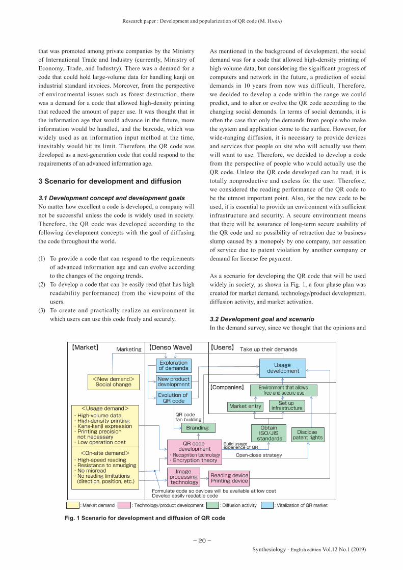
Research paper : Development and popularization of QR code (M. HARA)
−20−
Synthesiology - English edition Vol.12 No.1 (2019)
that was promoted among private companies by the Ministry of International Trade and Industry (currently, Ministry of Economy, Trade, and Industry). There was a demand for a code that could hold large-volume data for handling kanji on industrial standard invoices. Moreover, from the perspective of environmental issues such as forest destruction, there was a demand for a code that allowed high-density printing that reduced the amount of paper use. It was thought that in the information age that would advance in the future, more information would be handled, and the barcode, which was widely used as an information input method at the time, inevitably would hit its limit. Therefore, the QR code was developed as a next-generation code that could respond to the requirements of an advanced information age.
3 Scenario for development and diffusion
3.1 Development concept and development goalsNo matter how excellent a code is developed, a company will not be successful unless the code is widely used in society. Therefore, the QR code was developed according to the following development concepts with the goal of diffusing the code throughout the world.
(1) To provide a code that can respond to the requirements of advanced information age and can evolve according to the changes of the ongoing trends.
(2) To develop a code that can be easily read (that has high readability performance) from the viewpoint of the users.
(3) To create and practically realize an environment in which users can use this code freely and securely.
As mentioned in the background of development, the social demand was for a code that allowed high-density printing of high-volume data, but considering the significant progress of computers and network in the future, a prediction of social demands in 10 years from now was difficult. Therefore, we decided to develop a code within the range we could predict, and to alter or evolve the QR code according to the changing social demands. In terms of social demands, it is often the case that only the demands from people who make the system and application come to the surface. However, for wide-ranging diffusion, it is necessary to provide devices and services that people on site who will actually use them will want to use. Therefore, we decided to develop a code from the perspective of people who would actually use the QR code. Unless the QR code developed can be read, it is totally nonproductive and useless for the user. Therefore, we considered the reading performance of the QR code to be the utmost important point. Also, for the new code to be used, it is essential to provide an environment with sufficient infrastructure and security. A secure environment means that there will be assurance of long-term secure usability of the QR code and no possibility of retraction due to business slump caused by a monopoly by one company, nor cessation of service due to patent violation by another company or demand for license fee payment.
As a scenario for developing the QR code that will be used widely in society, as shown in Fig. 1, a four phase plan was created for market demand, technology/product development, diffusion activity, and market activation.
3.2 Development goal and scenarioIn the demand survey, since we thought that the opinions and
Market entry
【Companies】
【Users】【Denso Wave】【Market】
Open-close strategy
Marketing
<New demand>Social change
Take up their demands
Evolution of QR code
Branding
Build usageexperience of QR
QR code fan building
: Market demand : Diffusion activity: Technology/product development : Vitalization of QR market
Formulate code so devices will be available at low costDevelop easily readable code
New product development
Reading devicePrinting device
Image processing technology
・Recognition technology・Encryption theory
QR code development
Usage development
Explorationof demands
Environment that allows free and secure use
Disclose patent rights
Obtain ISO/JIS standards
Set up infrastructure
・High-speed reading・Resistance to smudging・No misread・No reading limitations (direction, position, etc.)
<On-site demand>
・High-volume data・High-density printing・Kana-kanji expression・Printing precision not necessary・Low operation cost
<Usage demand>
Fig. 1 Scenario for development and diffusion of QR code
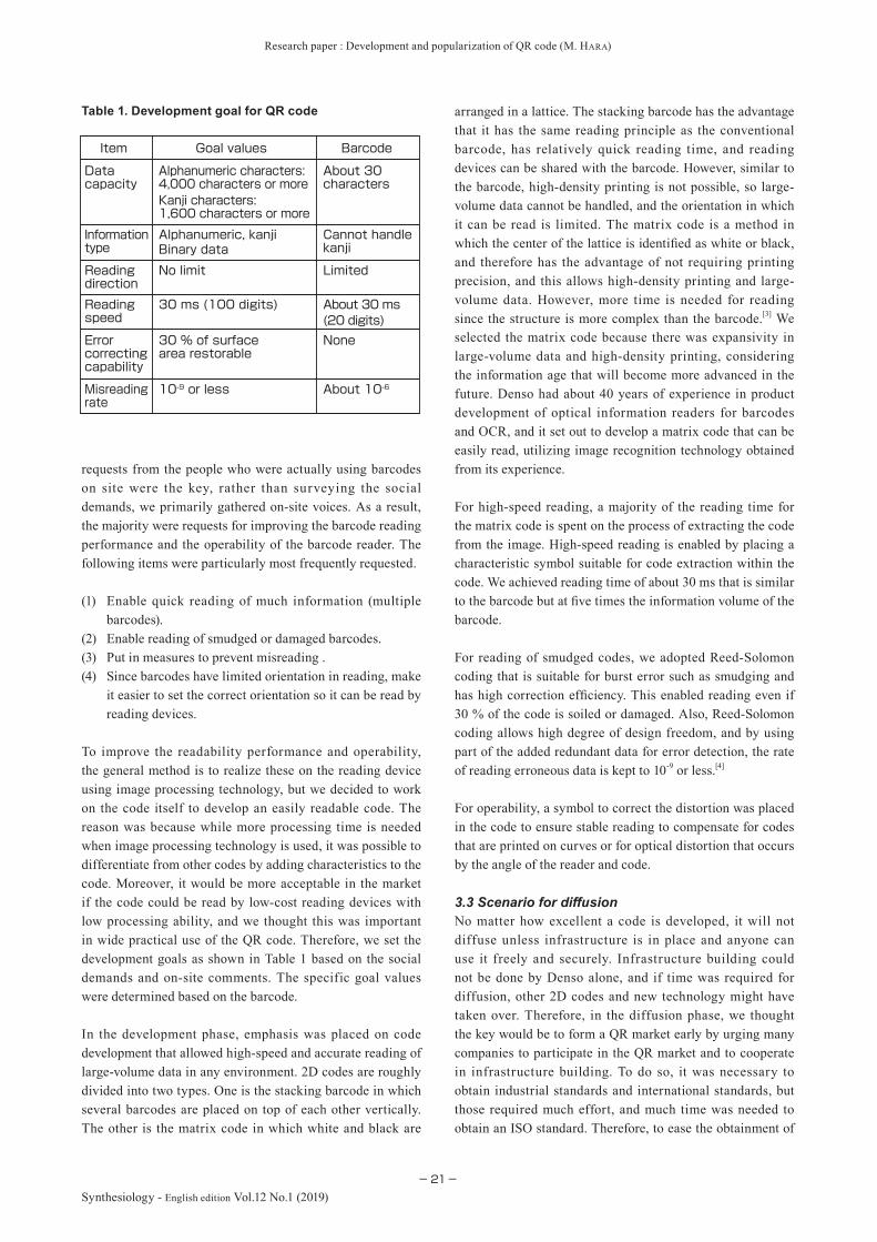
Research paper : Development and popularization of QR code (M. HARA)
−21−Synthesiology - English edition Vol.12 No.1 (2019)
requests from the people who were actually using barcodes on site were the key, rather than surveying the social demands, we primarily gathered on-site voices. As a result, the majority were requests for improving the barcode reading performance and the operability of the barcode reader. The following items were particularly most frequently requested.
(1) Enable quick reading of much information (multiple barcodes).
(2) Enable reading of smudged or damaged barcodes.(3) Put in measures to prevent misreading .(4) Since barcodes have limited orientation in reading, make
it easier to set the correct orientation so it can be read by reading devices.
To improve the readability performance and operability, the general method is to realize these on the reading device using image processing technology, but we decided to work on the code itself to develop an easily readable code. The reason was because while more processing time is needed when image processing technology is used, it was possible to differentiate from other codes by adding characteristics to the code. Moreover, it would be more acceptable in the market if the code could be read by low-cost reading devices with low processing ability, and we thought this was important in wide practical use of the QR code. Therefore, we set the development goals as shown in Table 1 based on the social demands and on-site comments. The specific goal values were determined based on the barcode.
In the development phase, emphasis was placed on code development that allowed high-speed and accurate reading of large-volume data in any environment. 2D codes are roughly divided into two types. One is the stacking barcode in which several barcodes are placed on top of each other vertically. The other is the matrix code in which white and black are
arranged in a lattice. The stacking barcode has the advantage that it has the same reading principle as the conventional barcode, has relatively quick reading time, and reading devices can be shared with the barcode. However, similar to the barcode, high-density printing is not possible, so large-volume data cannot be handled, and the orientation in which it can be read is limited. The matrix code is a method in which the center of the lattice is identified as white or black, and therefore has the advantage of not requiring printing precision, and this allows high-density printing and large-volume data. However, more time is needed for reading since the structure is more complex than the barcode.[3] We selected the matrix code because there was expansivity in large-volume data and high-density printing, considering the information age that will become more advanced in the future. Denso had about 40 years of experience in product development of optical information readers for barcodes and OCR, and it set out to develop a matrix code that can be easily read, utilizing image recognition technology obtained from its experience.
For high-speed reading, a majority of the reading time for the matrix code is spent on the process of extracting the code from the image. High-speed reading is enabled by placing a characteristic symbol suitable for code extraction within the code. We achieved reading time of about 30 ms that is similar to the barcode but at five times the information volume of the barcode.
For reading of smudged codes, we adopted Reed-Solomon coding that is suitable for burst error such as smudging and has high correction efficiency. This enabled reading even if 30 % of the code is soiled or damaged. Also, Reed-Solomon coding allows high degree of design freedom, and by using part of the added redundant data for error detection, the rate of reading erroneous data is kept to 10-9 or less.[4]
For operability, a symbol to correct the distortion was placed in the code to ensure stable reading to compensate for codes that are printed on curves or for optical distortion that occurs by the angle of the reader and code.
3.3 Scenario for diffusionNo matter how excellent a code is developed, it will not diffuse unless infrastructure is in place and anyone can use it freely and securely. Infrastructure building could not be done by Denso alone, and if time was required for diffusion, other 2D codes and new technology might have taken over. Therefore, in the diffusion phase, we thought the key would be to form a QR market early by urging many companies to participate in the QR market and to cooperate in infrastructure building. To do so, it was necessary to obtain industrial standards and international standards, but those required much effort, and much time was needed to obtain an ISO standard. Therefore, to ease the obtainment of
Table 1. Development goal for QR code
About 10-610-9 or lessMisreading rate
None30 % of surface area restorable
Error correcting capability
About 30 ms(20 digits)
30 ms (100 digits)Reading speed
LimitedNo limitReading direction
Cannot handle kanji
Alphanumeric, kanjiInformation type
About 30 characters
Alphanumeric characters: 4,000 characters or more
Data capacity
BarcodeGoal valuesItem
Kanji characters: 1,600 characters or more
Binary data
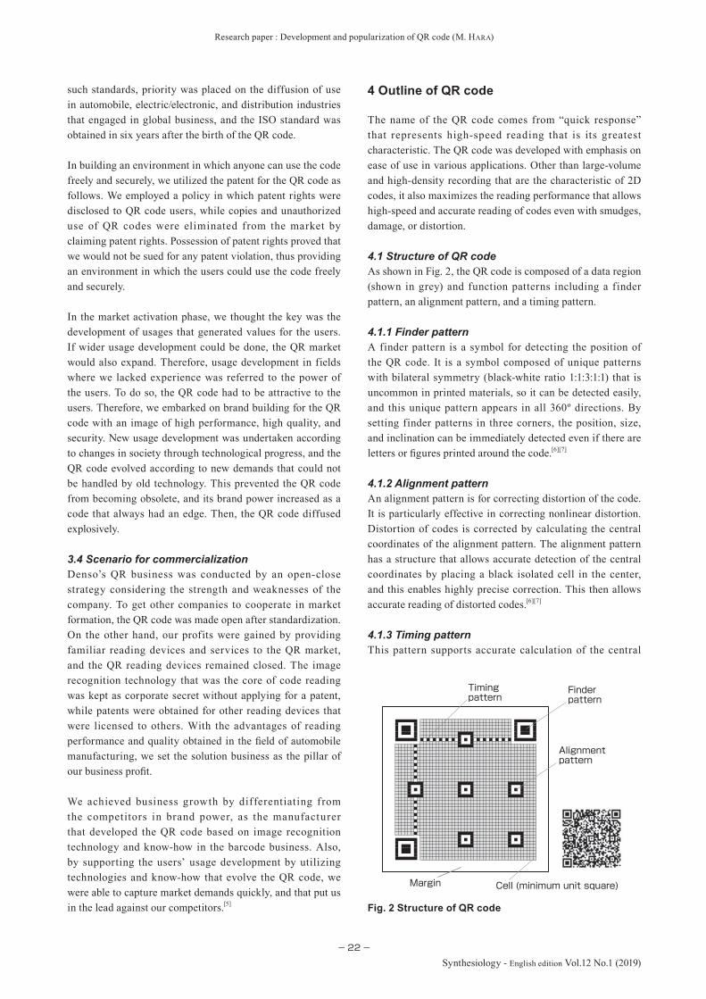
Research paper : Development and popularization of QR code (M. HARA)
−22−
Synthesiology - English edition Vol.12 No.1 (2019)
such standards, priority was placed on the diffusion of use in automobile, electric/electronic, and distribution industries that engaged in global business, and the ISO standard was obtained in six years after the birth of the QR code.
In building an environment in which anyone can use the code freely and securely, we utilized the patent for the QR code as follows. We employed a policy in which patent rights were disclosed to QR code users, while copies and unauthorized use of QR codes were eliminated from the market by claiming patent rights. Possession of patent rights proved that we would not be sued for any patent violation, thus providing an environment in which the users could use the code freely and securely.
In the market activation phase, we thought the key was the development of usages that generated values for the users. If wider usage development could be done, the QR market would also expand. Therefore, usage development in fields where we lacked experience was referred to the power of the users. To do so, the QR code had to be attractive to the users. Therefore, we embarked on brand building for the QR code with an image of high performance, high quality, and security. New usage development was undertaken according to changes in society through technological progress, and the QR code evolved according to new demands that could not be handled by old technology. This prevented the QR code from becoming obsolete, and its brand power increased as a code that always had an edge. Then, the QR code diffused explosively.
3.4 Scenario for commercializationDenso’s QR business was conducted by an open-close strategy considering the strength and weaknesses of the company. To get other companies to cooperate in market formation, the QR code was made open after standardization. On the other hand, our profits were gained by providing familiar reading devices and services to the QR market, and the QR reading devices remained closed. The image recognition technology that was the core of code reading was kept as corporate secret without applying for a patent, while patents were obtained for other reading devices that were licensed to others. With the advantages of reading performance and quality obtained in the field of automobile manufacturing, we set the solution business as the pillar of our business profit.
We achieved business growth by differentiating from the competitors in brand power, as the manufacturer that developed the QR code based on image recognition technology and know-how in the barcode business. Also, by supporting the users’ usage development by utilizing technologies and know-how that evolve the QR code, we were able to capture market demands quickly, and that put us in the lead against our competitors.[5]
4 Outline of QR code
The name of the QR code comes from “quick response” that represents high-speed reading that is its greatest characteristic. The QR code was developed with emphasis on ease of use in various applications. Other than large-volume and high-density recording that are the characteristic of 2D codes, it also maximizes the reading performance that allows high-speed and accurate reading of codes even with smudges, damage, or distortion.
4.1 Structure of QR codeAs shown in Fig. 2, the QR code is composed of a data region (shown in grey) and function patterns including a finder pattern, an alignment pattern, and a timing pattern.
4.1.1 Finder patternA finder pattern is a symbol for detecting the position of the QR code. It is a symbol composed of unique patterns with bilateral symmetry (black-white ratio 1:1:3:1:1) that is uncommon in printed materials, so it can be detected easily, and this unique pattern appears in all 360º directions. By setting finder patterns in three corners, the position, size, and inclination can be immediately detected even if there are letters or figures printed around the code.[6][7]
4.1.2 Alignment patternAn alignment pattern is for correcting distortion of the code. It is particularly effective in correcting nonlinear distortion. Distortion of codes is corrected by calculating the central coordinates of the alignment pattern. The alignment pattern has a structure that allows accurate detection of the central coordinates by placing a black isolated cell in the center, and this enables highly precise correction. This then allows accurate reading of distorted codes.[6][7]
4.1.3 Timing patternThis pattern supports accurate calculation of the central
Fig. 2 Structure of QR code
Timing pattern
Alignment pattern
Cell (minimum unit square)Margin
Finder pattern

Research paper : Development and popularization of QR code (M. HARA)
−23−Synthesiology - English edition Vol.12 No.1 (2019)
coordinates of each data cel l. The white and black patterns are placed alternately in two places vertically and horizontally between the finder patterns. Even if the code is distorted partially or cell pitch gaps occur due to poor printing, this allows accurate reading of central coordinates of the data cell.[6][7]
4.1.4 Data rangeQR code data are arranged in the data region shown in gray. The data are binarized in ‘0’ and ‘1’ according to rules. The ‘0’ is converted to white cells, and ‘1’ into black cells. The data region contains Reed-Solomon codes that realize error correction.[6][7]
4.2 Specifi cation of QR codeQR codes increase in size according to the stored volume of information, and the sizes range from 21 × 21 to a maximum of 177 × 177 cells, in intervals of 4 cells. It is possible to link 16 QR codes, and a maximum of about 46 kilobytes of data can be stored. Table 2 shows the outline of the specifi cations of the QR code.
5 Characteristics of QR code
Here, the characteristics of the QR code will be explained including particularly excellent high-speed reading, and the property that allows accurate reading even with smudging and damage.
5.1 All-direction high-speed readabilityNor mally, reading of 2D codes is done using a 2D image sensor. Image data read with a 2D image sensor is decompressed on the memory, analyzed in detail with software, and only the code is extracted. The position, size, and incline of the code are detected, and decoding is done by calculating the central coordinate of each cell. In general matrix codes, the captured image is searched with a software, and when a black part is detected, peripheral detection is conducted to determine whether it is a code, and if it is not a code, it moves to the next black part. Therefore, a majority of the time required for reading is spent on processing. Particularly, if there are noises such as patterns that look like letters in the background, the information volume that must be processed increases to about 800 times the amount of the barcode. This requires an extremely long time for processing, and reading performance seems inferior to the barcode. With the QR code, the fi nder pattern is placed in three corners to detect code location, and this enables high-speed scanning in all 360º directions. Figure 3 compares processing of a general matrix code and the QR code.
With the finder pattern of the QR code, the black-to-white ratio of the scan line that passes through the center of the fi nder pattern is 1:1:3:1:1 from all 360º directions, as shown in Fig. 4. With this unique ratio, it was found it had an extremely low chance of occurrence after surveying the black-white ratio that comprised the letters and fi gures. This
*In QR code, Level 1 and 2 JIS Kanji characters are compressed to 13 bits
☆Example of six links
Linkage of up to 16 codes is possible (Maximum about 46 Kbyte storage)
Linkagefunction
Restoration is possible even if about 7 %, 15 %, 25 %, or 30 % of code surface area are damaged (can be selected from 4 levels)
Data restoration function
Maximum 1,817 charactersKanji*Maximum 2,953 charactersBinary
Maximum 4,296 charactersAlphanumeric
Maximum 7,089 charactersNumeralType and volume of information
・Numerals 40 digits: 5.25 mm square・Numerals 7,089 digits: 44.25 mm square
☆ In cases cell size is 0.25 mm
Minimum 21 x 21 cellsMaximum 177 x 177 cells (4 cell intervals)
Size of code
SpecificationsItem
LY
X
θ
LY
X
θ
●In a case there are characters in the background of code
QR codeGeneral processing
:Code:Background noise
Code
extraction
Code
detection
Image
scanning
Table 2. Outline of specifi cations for QR code
Fig. 3 Detection processes of position and shape of code

Research paper : Development and popularization of QR code (M. HARA)
−24−
Synthesiology - English edition Vol.12 No.1 (2019)
ratio can be detected when the image is output from the 2D image sensor using raster scanning, and therefore the position of the QR code can be determined from an image including letters and figures, without searching the memory. From the positional relationship of the three finder patterns, the size and inclination of the code can be determined, and the shape of the code can be detected instantly.[8] Therefore, by detecting the finder pattern, to search for boundaries and periphery of the code symbol among scanned images becomes unnecessary, and the reading speed can be increased by about 50 times compared to processing a general matrix code.[7][9] This allows reading information volume five times the barcode at the same speed of 30 ms of the barcode, even using a versatile CPU (32 bit RISC CPU: 18 MIPS). The hardware for detection of finder patterns was easily created, and this allowed the shape of QR codes to be detected at the same time as image scanning. This enables image scanning at real-time for QR codes that are moving at high speed.
5.2 Resilience against smudges and damageFor the QR code, four levels were set in which recovery became possible even if 7 %, 15 %, 25 %, or 30 % of the code surface area are damaged, by employing Reed-Solomon coding that is the error correction code. In a clean environment such as an office, 7 % can be selected whereas 30 % can be selected in poor environments like a plant, and the choice can be made according to the environment or application.[6] It is designed so the error correction rate will be 10-9 or less in all code variations. To increase the scanning performance, measures are taken to arrange the black-white cells in a good balance, without unevenness. This process is called the mask process. As shown in Fig. 5, when placing the stored data in the data region after coding them, the EX-OR operation (WHITE if both cells are black or both are white, BLACK if not) is conducted between the cells for the data region and the cell for a mask pattern that has been prepared beforehand (template), and the pattern in which the black-white cells are most well balanced is used as the QR code.[10] Arranging the black-white cells in a good balance allows reading of QR codes with particularly poor uneven luminance. In a general binary-coded process, a luminance histogram of the image is taken, and using the luminance T1 of the valley part as a threshold value, the luminance T1 or more is set as white cells while luminance of less than T1 is set as black cells. When this is done, the left part of a QR code tends to have more white cells while there will be more
black cells on the right part, and it can be understood that the binary threshold value T1 is bad. To remedy this, valleys T2 and T3 are set in places with lower and higher luminance than threshold T1, and if the regions with more white cells are processed as threshold T3 and regions with more black cells as threshold T2, it is possible to accurately determine the black-white of the cells. This allows scanning of poor quality QR codes.
6 Evolution of QR code
Since the birth of the QR code, new QR codes were developed and advanced in the four categories, “miniaturization,” “increased volume,” “design,” and “security,” considering the creation of user value by capturing the changes in social demand. Figure 6 shows the history of the progress of the QR code.
With the arrival of the QR code, there were increased demands for managing small products and micro-size components such as electronic components, pharmaceuticals, and precious metals that could not be managed with barcodes. Therefore, a micro QR code was developed in 1998, and this allowed data of about 20 alphanumeric characters that included product codes and serial numbers to be printed in a 1 mm square, while maintaining the reading performance of the QR code. Moreover, responding to the demand for management of small, cylindrical products and test tubes with tight curves from the medical field and manufacturing plants, iQR codes that support rectangular shapes with increased data efficiency was developed in 2008. When Japanese companies went to Asia such as China
Fig. 5 Effect of mask processing
(c)
(b)
(a)
31 1 11
(c)
(b)
(a)
31 1 11
31 1 11
● Mask process
● Binarization process
Lots of black cells
Lots of white cells
Bad quality code (uneven brightness)
Threshold
Binarization
T1
T2 T3
T2T3
Shift threshold, binarization
Select one
Mask processing result
Mask pattern
Original
Fig. 4 Characteristics of finder pattern

Research paper : Development and popularization of QR code (M. HARA)
−25−Synthesiology - English edition Vol.12 No.1 (2019)
in 2000, there were demands for efficient handling of non-Japanese kanji and hangul, that are non-alphanumeric, multi-byte characters. Therefore, QR codes that incorporated Asian languages including kanji of China and Taiwan and hangul of Korea were developed in 2001. National standards of Asian countries were obtained.
For security, due to the diffusion of mobile phones with functions that enabled QR code reading since 2004, anyone could read QR codes, and there was the issue that QR codes that were primarily used by companies for invoice control could be easily read by customers. To solve this issue, SQRC was developed in 2007. The greatest characteristic of SQRC was the two-layer structure of an open information region and a closed information region. The open information region can be read by all scanning devices including mobile phones, while the closed region has encrypted information that can be read only by scanning devices that have matching encryption keys and SQRC recognition software for decoding. With this SQRC encryption function, the demand for use in tickets increased as a new usage, as the data could not be altered. However, since it could be easily duplicated with copiers, it could not be used in expensive tickets. Therefore, a copy-guarded QR code in which the printed SQRC was covered with ink that passed special light and could not be duplicated or altered was developed in 2011. The technology in which luminescent ink shines when irradiated with black light (UV) is known, but copy-guarded QR codes are invisible to the naked eye even when irradiated with light of a special wavelength, and one cannot tell where the SQRC is, and that increases the security.
In terms of design, social networks dramatically diffused since 2005, and many people started to create QR codes of companies or personal addresses. Against such a background, there was increased demand for one’s original QR code, and the companies demanded QR codes that were unique looking that caught people’s attention and made them want to access company websites. Therefore, frame QR was developed in 2014. Frame QR is a code with reading performance of the original QR code by setting a special canvas that hold an image or logo in the center of the code.[11] This increases the design property, but also increases convenience since images or illustrations indicate the kind of information sites one can expect to access. The QR market expanded with the evolution of the QR code that responded to social demands.
7 Spread of QR code
Figure 7 shows the spread of the QR code. In the 1990s, since it was used mainly in the fi elds of manufacturing and distribution, QR codes were not visible to the general public.
In 2000, the ISO standard was set, and QR codes were used for betting tickets, vehicle inspection stickers, and airline tickets. In 2002, when QR codes became readable with mobile phones, they were used for accessing websites, and they appeared in newspapers, magazines, and posters, and by this time, everyone knew what the QR codes were.[12] The use in public, administration, and distribution increased around that time, and the QR market suddenly expanded.
Since 2005, social networks spread widely, and the QR code was used as a communication tool to connect personal
Handling of multi-byte characters
Handling of Chinese and Korean characters (‘01)
・Improvement of design property
Frame QR (‘14)
(Printing on micro-size parts and cylindrical parts)
(Authenticity of ticket, brand, products)
・Prevent copying of QR code
(management of small electronic parts)Mi
niaturization
Security
Design
Large
volume
Copy guarded QR code (‘11)SQRC(‘07)
100094 year
・Rectangular・Further high-density
・Two-layer structure of open and closed area (use on tickets)・Prevent unauthorized copying and alteration of QR code
・Micro-sizing・High-speed reading・High capacity・Small printout size・Japanese characters
iQR Code(‘08)Micro QR (‘98)QR code (‘94)
Fig. 6 Evolution of QR code
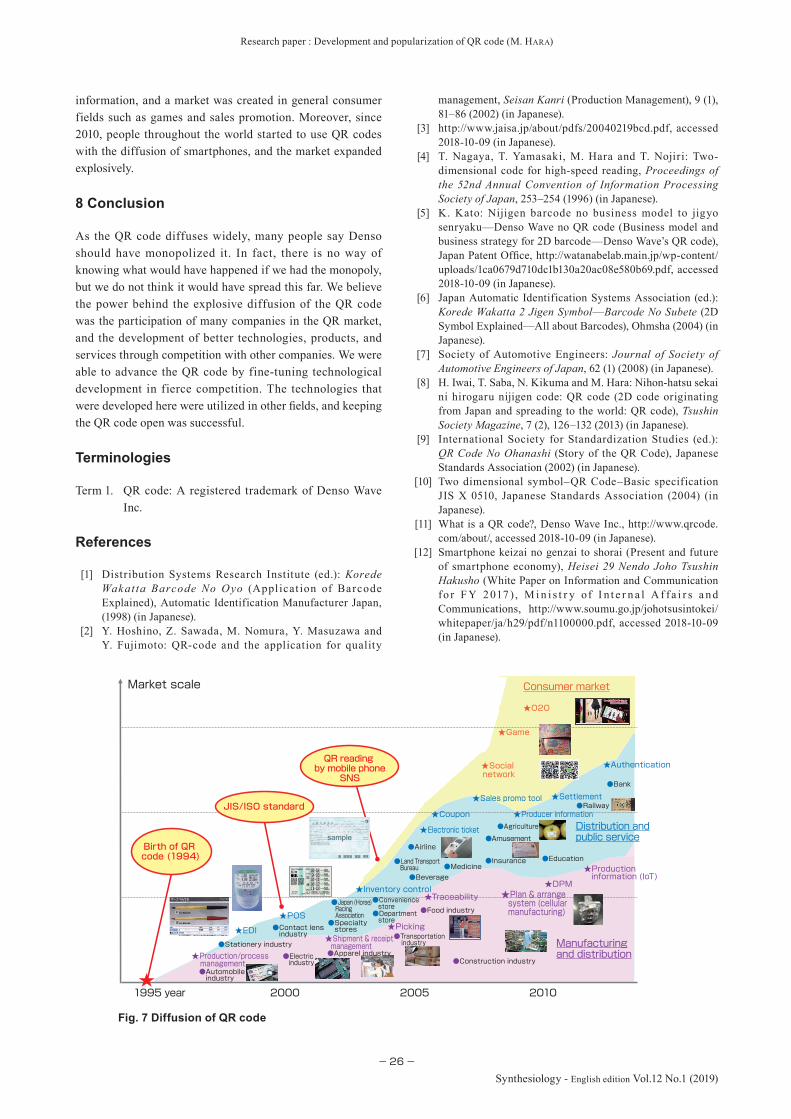
Research paper : Development and popularization of QR code (M. HARA)
−26−
Synthesiology - English edition Vol.12 No.1 (2019)
information, and a market was created in general consumer fields such as games and sales promotion. Moreover, since 2010, people throughout the world started to use QR codes with the diffusion of smartphones, and the market expanded explosively.
8 Conclusion
As the QR code diffuses widely, many people say Denso should have monopolized it. In fact, there is no way of knowing what would have happened if we had the monopoly, but we do not think it would have spread this far. We believe the power behind the explosive diffusion of the QR code was the participation of many companies in the QR market, and the development of better technologies, products, and services through competition with other companies. We were able to advance the QR code by fine-tuning technological development in fierce competition. The technologies that were developed here were utilized in other fields, and keeping the QR code open was successful.
QR reading by mobile phone
SNS
JIS/ISO standard
●Automobile industry
●Construction industry
★Game
★Social network
★DPM
Consumer market
●Japan (Horse) Racing Association
●Agriculture
★Settlement
★Plan & arrange system (cellular manufacturing)
★Producer information
★Sales promo tool
●Education●Insurance●Land Transport Bureau
●Bank
★Authentication
★O2O
★Production information (IoT)
★Picking
★Inventory control
★Coupon
★Shipment & receipt management
★Traceability
★Production/process management
●Transportation industry
Market scale
★EDI
★POS
★Electronic ticket
●Railway
●Amusement●Airline
●Medicine●Beverage
●Specialty stores●Contact lens
industry●Stationery industry
●Department store
●Convenience store
●Apparel industry●Electric industry
●Food industry
Manufacturingand distribution
2010200520001995 year
Distribution andpublic service
Birth of QR code (1994)
Fig. 7 Diffusion of QR code
Terminologies
Term 1. QR code: A registered trademark of Denso Wave Inc.
References
[1] Distribution Systems Research Institute (ed.): Korede Wakat ta Barcode No Oyo (Appl icat ion of Barcode Explained), Automatic Identification Manufacturer Japan, (1998) (in Japanese).
[2] Y. Hoshino, Z. Sawada, M. Nomura, Y. Masuzawa and Y. Fujimoto: QR-code and the application for quality
management, Seisan Kanri (Production Management), 9 (1), 81–86 (2002) (in Japanese).
[3] http://www.jaisa.jp/about/pdfs/20040219bcd.pdf, accessed 2018-10-09 (in Japanese).
[4] T. Nagaya, T. Yamasaki, M. Hara and T. Nojiri: Two-dimensional code for high-speed reading, Proceedings of the 52nd Annual Convention of Information Processing Society of Japan, 253–254 (1996) (in Japanese).
[5] K. Kato: Nijigen barcode no business model to jigyo senryaku—Denso Wave no QR code (Business model and business strategy for 2D barcode—Denso Wave’s QR code), Japan Patent Office, http://watanabelab.main.jp/wp-content/uploads/1ca0679d710dc1b130a20ac08e580b69.pdf, accessed 2018-10-09 (in Japanese).
[6] Japan Automatic Identification Systems Association (ed.): Korede Wakatta 2 Jigen Symbol—Barcode No Subete (2D Symbol Explained—All about Barcodes), Ohmsha (2004) (in Japanese).
[7] Society of Automotive Engineers: Journal of Society of Automotive Engineers of Japan, 62 (1) (2008) (in Japanese).
[8] H. Iwai, T. Saba, N. Kikuma and M. Hara: Nihon-hatsu sekai ni hirogaru nijigen code: QR code (2D code originating from Japan and spreading to the world: QR code), Tsushin Society Magazine, 7 (2), 126–132 (2013) (in Japanese).
[9] International Society for Standardization Studies (ed.): QR Code No Ohanashi (Story of the QR Code), Japanese Standards Association (2002) (in Japanese).
[10] Two dimensional symbol–QR Code–Basic specification JIS X 0510, Japanese Standards Association (2004) (in Japanese).
[11] What is a QR code?, Denso Wave Inc., http://www.qrcode.com/about/, accessed 2018-10-09 (in Japanese).
[12] Smartphone keizai no genzai to shorai (Present and future of smartphone economy), Heisei 29 Nendo Joho Tsushin Hakusho (White Paper on Information and Communication fo r F Y 2017 ) , M i n i s t r y of I n t e r n a l A f f a i r s a nd Communications, http://www.soumu.go.jp/johotsusintokei/whitepaper/ja/h29/pdf/n1100000.pdf, accessed 2018-10-09 (in Japanese).
Research paper : Development and popularization of QR code (M. HARA)
−27−Synthesiology - English edition Vol.12 No.1 (2019)
Authors
Masahiro HARAGraduated f rom the Depar tment of Electrical and Electronic Engineering, Faculty of Science and Engineering, Hosei Univeristy in March 1980. Joined Nippon Denso K.K. (currently Denso Corporation) in April 1980. Transferred to Denso Wave Incorporated in January 2012, and currently Senior Engineer. Also Technological Consultant for Kota Manufacturing Research Center, Aichi Prefecture from January 2018. Has engaged in development of barcode, OCR, QR code, recognition algorithm for QR code, and reading devices. Major awards received include the following: Special Encouragement Award, Chunichi Industrial Technology Award (2002); R&D 100 Awards (2002); Best Project, Mobile Project Award (2004); Excellence Award, Japan Innovator Prize (2007); Best 100, Good Design Award (2012); and European Inventor Award (2014).
We obtained patents for items that were newly developed for the QR code, to prove that we were not violating any other patent in the disclosed QR code. We prioritized the patents for the reading/scanning devices that are the pillar of our business.
If we found any copy products or unauthorized use, we would issue warnings that they were violating our patent rights, and if they did not stop after receiving the warnings, we would proceed to exercise our patent rights. Up to this moment, we have issued only one warning against a copy product.
When we were developing the QR code, we did not assume that the smartphone would become capable of reading QR codes. Denso considered various B to B usages, but we didn’t consider B to C as part of our business due to Denso’s corporate culture.
3 BrandingQuestion (Motoyuki Akamatsu)
You mentioned that branding was one of the strategies. What were your branding measures for “building an image of high-performance, high quality, and security”?Answer (Masahiro Hara)
By disclosing the QR code and getting many companies to participate, many reading and printing products were created by companies other than Denso Wave. If the product performance of products by companies other than Denso Wave was poor, the excellent characteristic of the QR code could not be presented. Therefore, the know-how of reading and printing was disclosed to ensure minimum performance and quality that would not hinder operation. We created a booklet called QR Code Dokuhon (Guide to QR Codes) to get people to understand the excellence of the QR code, and these were distributed to the users as part of our educational campaign.
4 Diffusion of technology through standardizationQuestion (Toshihiro Matsui)
Your discussion of the diffusion scenario is very interesting. How did you gain usage experience in the early stages, when no one was using the code, and what kind of promotion did you do at the time? Also, at the stage when future potential was unclear, how did you convince your superiors that the development should go on? On the standardization to promote diffusion, what was the background for achieving standardization in six years? What specific actions did you take in borrowing user power in usage development?Answer (Masahiro Hara)
First, we obtained opportunities to do presentations for the QR code at various industrial meetings, where we conducted demonstrations for high-speed scanning and accurate reading even when the code was smudged or damaged. We later visited the companies that showed interest, offered detailed explanation of the QR code, and these efforts led to adoption.
At the beginning, since we didn’t know whether we would be successful, we started with two people and started from code development that did not involve any development cost. We convinced our superiors that we would move to reading device development only after the code was completed and if people showed interest when we did demonstrations in front of potential users. Therefore, product realization of reading devices was started two years after the completion of the QR code.
For standardization, we were able to do so quickly, because we aggressively built experience in the automobile, electric/electronic, and distribution industries that were engaging in global business, and the industries themselves requested ISO standardization.
For usage development, we listened to the users who discussed the issues in their daily operation and how they wanted
Discussions with Reviewers
1 OverallComment (Motoyuki Akamatsu, AIST)
This paper discusses the course of development of the QR code, a two-dimensional barcode, and its diffusion strategy. It explains carefully the technological points of optical codes, including information volume, rotation, and anti-smudge measures. It also presents the goals set based on social situations at the commencement of development, diffusion strategies such as branding, and the fact that a bold policy of disclosing the patent led to wide spread use. It is greatly helpful as a scenario for technological development and diffusion to society.Comment (Toshihiro Matsui, Institute of Information Security)
The QR code is a widely used pattern code developed by a Japanese company, and is a highly rated system that allows the code to be used freely. To have the course of its development published in Synthesiology will help the readers in seeking methods for diffusing original technology.
2 Intellectual property in open-close strategyQuestion (Toshihiro Matsui)
You mention that you employed the open-close strategy, but doesn’t registering the QR code as a trademark limit its use? I think to disclose the technology while obtaining a patent is a brilliant strategy, but did you consider what kind of patent should be obtained? You say you use the patent to eliminate copies and unauthorized use, but how specifi cally did you do so? Pertaining to the undisclosed part, at the time of development, did you ever suppose that it will become possible to read the code with a smartphone, without using a special scanning device?Answer (Masahiro Hara)
Concerning a registered trademark, as the number one strategy for the diffusion of the QR code, we attempted to establish a brand image that the QR code is an excellent code. When the QR code was in the process of diffusion, other 2D codes could have called themselves the QR code. Since the reputation of the QR code could be jeopardized if the performances of those 2D codes were bad, we obtained a registered trademark so other poor quality 2D codes could not call themselves the QR code.

Research paper : Development and popularization of QR code (M. HARA)
−28−
Synthesiology - English edition Vol.12 No.1 (2019)
to be, and we proposed methods to realize their demands using the QR code.
5 Characteristic technology of QR codeQuestion (Toshihiro Matsui)
In Chapter 4, you explain the ease of use, volume, reading performance, and reliability of the QR technology. I think one of the definitive characteristics of the QR code is the finder pattern. The finder pattern is unique as a printed matter, can be detected even if rotated, and is readable by one-dimensional linear scanning. However, if you were looking for rotational invariance, why didn’t you use concentric circles?Answer (Masahiro Hara)
The reason why we did not make the f inder pattern in concentric circles is because when the code is printed with a low-resolution printer, the circles must be made bigger. Compared to squares, circles require more dots in printing. Considering that codes may have to be printed in small printing areas, we decided to use squares.
6 Difference from competitor technologyQuestion (Toshihiro Matsui)
How is the situation of the diffusion of the QR code overseas? In the field of pharmaceuticals, Datamatrix and Databar Limited have been standardized, but how are they different from the QR code?
Answer (Masahiro Hara)The QR code is used widely around the world. Databar
Limited is a type of barcode, and it cannot hold a lot of information. Therefore, it is not used much in areas other than pharmaceuticals. Datamatrix is used in American industries for data up to 40 digits, but the reading performance drops if it is packed with information. Therefore, the QR code is widely used for usage that involves storing lots of information.
7 Evolution of QR codeQuestion (Motoyuki Akamatsu)
You mentioned that you intend to “evolve the QR code according to social demands.” You give specific examples of evolution such as iQR, SQRC, and illustration design. What were the points in making it capable of handling a great deal of information?Answer (Masahiro Hara)
To accurately read much information quickly, we worked on data arrangement and readable code composition (arrangement of functional cells) considering code recognition technology. We also worked on reducing the size of code as much as possible by efficient compression. For example, Level 1 and Level 2 JIS kanji characters are compressed to 13 bits, and “https://www.” and other keywords frequently used in industry are set as 1-bit reserved words.
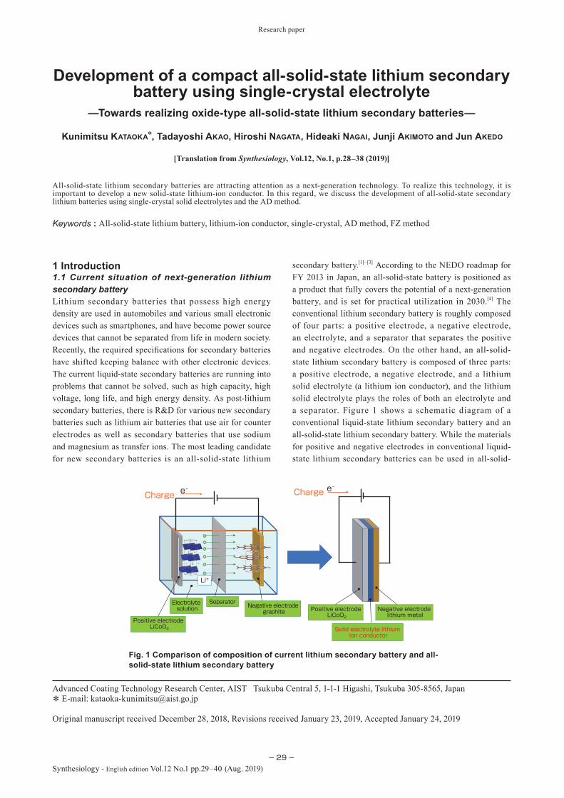
Research paper
−29−Synthesiology - English edition Vol.12 No.1 pp.29–40 (Aug. 2019)
secondary battery.[1]–[3] According to the NEDO roadmap for FY 2013 in Japan, an all-solid-state battery is positioned as a product that fully covers the potential of a next-generation battery, and is set for practical utilization in 2030.[4] The conventional lithium secondary battery is roughly composed of four parts: a positive electrode, a negative electrode, an electrolyte, and a separator that separates the positive and negative electrodes. On the other hand, an all-solid-state lithium secondary battery is composed of three parts: a positive electrode, a negative electrode, and a lithium solid electrolyte (a lithium ion conductor), and the lithium solid electrolyte plays the roles of both an electrolyte and a separator. Figure 1 shows a schematic diagram of a conventional liquid-state lithium secondary battery and an all-solid-state lithium secondary battery. While the materials for positive and negative electrodes in conventional liquid-state lithium secondary batteries can be used in all-solid-
1 Introduction1.1 Current situation of next-generation lithium secondary batteryLithium secondary batteries that possess high energy density are used in automobiles and various small electronic devices such as smartphones, and have become power source devices that cannot be separated from life in modern society. Recently, the required specifi cations for secondary batteries have shifted keeping balance with other electronic devices. The current liquid-state secondary batteries are running into problems that cannot be solved, such as high capacity, high voltage, long life, and high energy density. As post-lithium secondary batteries, there is R&D for various new secondary batteries such as lithium air batteries that use air for counter electrodes as well as secondary batteries that use sodium and magnesium as transfer ions. The most leading candidate for new secondary batteries is an all-solid-state lithium
—Towards realizing oxide-type all-solid-state lithium secondary batteries—
All-solid-state lithium secondary batteries are attracting attention as a next-generation technology. To realize this technology, it is important to develop a new solid-state lithium-ion conductor. In this regard, we discuss the development of all-solid-state secondary lithium batteries using single-crystal solid electrolytes and the AD method.
Development of a compact all-solid-state lithium secondary battery using single-crystal electrolyte
Keywords : All-solid-state lithium battery, lithium-ion conductor, single-crystal, AD method, FZ method
[Translation from Synthesiology, Vol.12, No.1, p.28–38 (2019)]
Kunimitsu KATAOKA*, Tadayoshi AKAO, Hiroshi NAGATA, Hideaki NAGAI, Junji AKIMOTO and Jun AKEDO
Advanced Coating Technology Research Center, AIST Tsukuba Central 5, 1-1-1 Higashi, Tsukuba 305-8565, Japan* E-mail: [email protected]
Original manuscript received December 28, 2018, Revisions received January 23, 2019, Accepted January 24, 2019
Solid electrolyte lithium ion conductor
Electrolyte solution
Separator
Li+
e- e-ChargeCharge
Positive electrode LiCoO2
Positive electrode LiCoO2
Negative electrode lithium metal
Negative electrode graphite
Fig. 1 Comparison of composition of current lithium secondary battery and all-solid-state lithium secondary battery

Research paper : Development of a compact all-solid-state lithium secondary battery using single-crystal electrolyte (K. KATAOKA et al.)
−30−
Synthesiology - English edition Vol.12 No.1 (2019)
state lithium secondary batteries, a lithium solid electrolyte must be newly developed. An all-solid-state lithium secondary battery that uses this lithium solid electrolyte is expected to have several advantages such as reduced internal resistance and operating voltage, and a bipolar all-solid-state lithium secondary battery that enables increased output is expected to have more advantages such as high voltage, high capacity, long life, simplified packaging, and possibility of using lithium metal negative electrodes. Currently, research institutions and companies around the world are engaging in the development of all-solid-state lithium secondary batteries. In this paper, a lithium solid electrolyte is defi ned as a solid-state electrolyte through which lithium ions move.
1.2 Problems of all-solid-state lithium secondary battery and all-solid-state lithium secondary battery that Advanced Coating Technology Research Center has in viewVarious kinds of R&D are being actively conducted for all-solid-state lithium secondary batteries, from component development for lithium solid electrolytes to battery design of all-solid-state lithium secondary batteries.[5] Table 1 summarizes the characteristics of the main lithium solid electrolyte for which development is being currently conducted. Sulfide solid electrolytes have high lithium ion conductivity and plasticity. While these characteristics are advantageous in battery fabrication, they are disadvantageous from a safety perspective as harmful hydrogen sulfi de gas is produced when many of the component materials used react with water. Since lithium secondary batteries are familiar devices used in everyday life, safety must be guaranteed, and the Advanced Coating Technology Research Center (hereinafter, the Center) engages in the development of all-solid-state lithium secondary batteries that use oxide solid electrolytes with high safety, although there are still issues. Figure 2, an overview of the current situation of
lithium secondary batteries and future prospects, shows the positioning of the all-solid-state lithium secondary battery that the Center sets as the goal. Although it is still diffi cult to achieve high capacity and high output with oxide all-solid-state lithium secondary batteries because large surface area is needed, it is thought to excel in higher safety, longer life, and better environmental resistance compared to sulfide all-solid-state lithium secondary batteries. It is thought that the goal should be the creation of small all-solid-state lithium secondary batteries that take advantage of these characteristics and can be used in the Internet of Things (IoT), wearable devices, and medical use.
1.3 Problems and solutions for garnet-type lithium solid electrolyteThe Center has been engaging in the development of oxide materials for positive and negative electrodes used in conventional lithium secondary batteries, before starting
Flammable--------Easy
Easy
Easy
Easy
Easy
Impossible Impossible10-2Standard: Current organic electrolyte solution
Hydrogen sulfide gas produced
1.0 × 10⁻²Li7P3S11
Hydrogen sulfide gas produced
1.2 × 10⁻²Li10GeP2S12
Sulfide
4.0 × 10⁻⁴Li1.5Al0.5Ge1.5(PO4)3
3.3 × 10⁻⁶Li2.9PO3.3N0.46
7.0 × 10⁻⁴Li1.3Al0.3Ti1.7(PO4)3
Impossible
Impossible
Impossible
Impossible
6.8 × 10⁻⁴La0.57Li0.29TiO3
Safe
Safe
Safe
Safe
Safe
Difficult
Difficult
Difficult
Difficult
Possible
Possible
PossiblePossible
Possible
Possible
Possible
Possible
Possible
PossiblePossible
Possible
Possible
Possible
Possible
Possible3.0 × 10-4Li7La3Zr2O12
Oxide
SafetyDenseness as component material
Formation of interface
with electrode
Use of high-potential positive electrode
Use of lithium metal negative electrode
Lithium ion conductivity(S cm-1)
Chemical composition
Table 1. Reported representative examples of reported lithium solid electrolytes
Fig. 2 Overview of current situation of lithium secondary battery and future prospects
LI
2010 2015 2020 20302025Year
Conventional liquid lithium ion secondary battery
Improved liquid lithium ion secondary battery
Lithium air battery
Lithium sulfur batter
Sulfide all-solid-state lithium secondary battery
Next-generation secondary battery
Oxide all-solid-state lithium secondary battery
All-solid-state battery set as the Center’s goalOxide all-solid-state battery using solid electrolyte single crystal and AD methodUse: IoT, wearables, medical useUse: cell phone, laptop PC
Use: Electric vehicle
High capacity
High safetyLong lifespanEnvironment resistance
High capacityHigh output
Energy density
Use: HEV, PHEV, smart phone

Research paper : Development of a compact all-solid-state lithium secondary battery using single-crystal electrolyte (K. KATAOKA et al.)
−31−Synthesiology - English edition Vol.12 No.1 (2019)
the research for all-solid-state lithium secondary batteries. Recently, we have become more involved in R&D for all-solid-state lithium secondary batteries, and we have concentrated our R&D on a garnet-type among the oxide lithium solid electrolytes. Research of garnet-type lithium solid electrolytes is being conducted at research institutes and companies around the world. In general, the bulk body is fabricated by a sintering method, but garnet-type lithium solid electrolytes are broken down by high temperature, and there are disadvantages that lithium evaporates, and sintered density of the sintered body cannot be increased. The sintered density has been increasing every year though low-temperature sintering achieved by densification of garnet-type lithium solid electrolytes and the spark plasma sintering (SPS) method. However, grain boundaries are always present in the sintered body, and grain boundary resistance when lithium ions pass between the grains is large, so it is difficult to bring out the original performance of the bulk body. Therefore, it may be possible to bring out the original lithium ion conductivity performance of the bulk body if one large grain without any granular boundaries is used, that is, by growing a large single crystal solid electrolyte. In an oxide all-solid-state lithium secondary battery that uses a sintered body of the garnet-type lithium solid electrolyte, there is the problem that lithium metal needles grow like dendrites in the solid electrolyte during precipitation of lithium metal. In papers, it is reported that lithium metal dendrites may cause short-circuits in all-solid-state lithium secondary batteries.[6] To solve this issue, we thought it was necessary to create a single crystal of a lithium solid electrolyte that is a bulk body without any grain boundaries.
To overcome the issues of garnet-type lithium solid electrolytes, the Center started development of large garnet-type lithium solid electrolytes without grain boundaries by utilizing a single crystal growing technology that it has been developed over the years. If the disadvantage of a garnet-type lithium solid electrolyte could be overcome by obtaining a single crystal, it was expected to be a breakthrough technology as a component for oxide all-solid-state lithium secondary batteries. There had been no successful growth of single crystals for large lithium solid electrolytes, including garnet-type lithium solid electrolytes.
Therefore, the growth of single crystals for lithium solid electrolytes was a meaningful research topic as an academic elemental technology for solid-state ionics that investigates the movement of lithium ions in solids, as well as for the field of all-solid-state lithium secondary batteries. Also, an ideal interface could be created by using single crystals of lithium solid electrolytes, and it was thought possible to clarify the interface structure that could not be shown in a sintered body.
1.4 Problems and solutions for formation of solid-solid interfaceIn fabricating an oxide all-solid-state lithium secondary battery, we worked on the issue of how to bond single crystals of garnet-type lithium solid electrolytes and the electrode layer. For the fabrication of an electrode for all-solid-state lithium secondary batteries, an integral sintering method, fabrication of thin film batteries by a sol-gel method, and pulse laser deposition (PLD) methods have been reported. Table 2 summarizes the methods and characteristics of major fabrication methods of oxide all-solid-state lithium secondary batteries. In all methods, it is necessary to form a strong boundary surface between the lithium solid electrolyte and the electrode layer. In the garnet-type lithium solid electrolyte, integral sintering at high temperature is difficult because of formation of different phases, which is a reactive product at solid interfaces between electrodes and solid electrolytes due to the mutual diffusion of electrodes and solid electrolytes at high temperature. Therefore, we focused on the development of an electrode layer fabrication technology by the aerosol deposition (AD) method that uses a room-temperature impact consolidation (RTIC) that was researched and developed over the years as a thick film ceramics coating technology at the Center. We thought the problem could be solved by applying a room-temperature bonding technology using the AD method that is a film forming process at room temperature. While various cases of usage are considered for all-solid-state lithium secondary batteries, we are aiming for the fabrication of a bulk-type all-solid-state lithium secondary battery that has high battery capacity. Therefore, to fabricate a bulk-type all-solid-state lithium secondary battery, we thought an all-
Fabrication method of all-solid-state battery
Film thickness of electrode layer
Degree of freedom of material selection
Fabricationtemperature
Integral sintering method Bulk-type battery Low Approx. 1000 ºC
Sol-gel method Thin film battery Low Approx. 800 ºC
PLD method Thin film battery High Approx. 400 ºC
AD method Bulk-type battery High Approx. 25 ºC
Table 2. Fabrication methods of major oxide all-solid-state lithium secondary battery and their characteristics
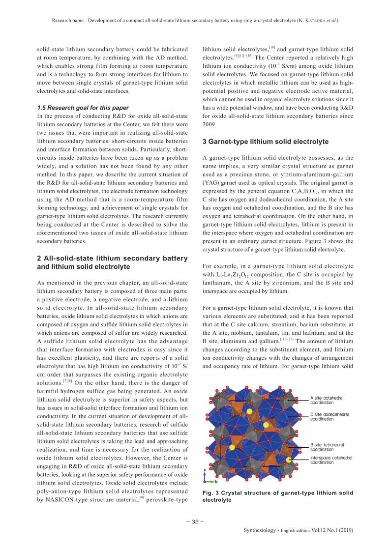
Research paper : Development of a compact all-solid-state lithium secondary battery using single-crystal electrolyte (K. KATAOKA et al.)
−32−
Synthesiology - English edition Vol.12 No.1 (2019)
solid-state lithium secondary battery could be fabricated at room temperature, by combining with the AD method, which enables strong film forming at room temperature and is a technology to form strong interfaces for lithium to move between single crystals of garnet-type lithium solid electrolytes and solid-state interfaces.
1.5 Research goal for this paperIn the process of conducting R&D for oxide all-solid-state lithium secondary batteries at the Center, we felt there were two issues that were important in realizing all-solid-state lithium secondary batteries: short-circuits inside batteries and interface formation between solids. Particularly, short-circuits inside batteries have been taken up as a problem widely, and a solution has not been found by any other method. In this paper, we describe the current situation of the R&D for all-solid-state lithium secondary batteries and lithium solid electrolytes, the electrode formation technology using the AD method that is a room-temperature f ilm forming technology, and achievement of single crystals for garnet-type lithium solid electrolytes. The research currently being conducted at the Center is described to solve the aforementioned two issues of oxide all-solid-state lithium secondary batteries.
2 All-solid-state lithium secondary battery and lithium solid electrolyte
As mentioned in the previous chapter, an all-solid-state lithium secondary battery is composed of three main parts: a positive electrode, a negative electrode, and a lithium solid electrolyte. In all-solid-state lithium secondary batteries, oxide lithium solid electrolytes in which anions are composed of oxygen and sulfide lithium solid electrolytes in which anions are composed of sulfur are widely researched. A sulf ide lithium solid electrolyte has the advantage that interface formation with electrodes is easy since it has excellent plasticity, and there are reports of a solid electrolyte that has high lithium ion conductivity of 10-2 S/cm order that surpasses the existing organic electrolyte solutions.[7][8] On the other hand, there is the danger of harmful hydrogen sulfide gas being generated. An oxide lithium solid electrolyte is superior in safety aspects, but has issues in solid-solid interface formation and lithium ion conductivity. In the current situation of development of all-solid-state lithium secondary batteries, research of sulfide all-solid-state lithium secondary batteries that use sulfide lithium solid electrolytes is taking the lead and approaching realization, and time is necessary for the realization of oxide lithium solid electrolytes. However, the Center is engaging in R&D of oxide all-solid-state lithium secondary batteries, looking at the superior safety performance of oxide lithium solid electrolytes. Oxide solid electrolytes include poly-anion-type lithium solid electrolytes represented by NASICON-type structure material,[9] perovskite-type
lithium solid electrolytes,[10] and garnet-type lithium solid electrolytes.[4][11]–[19] The Center reported a relatively high lithium ion conductivity (10-4 S/cm) among oxide lithium solid electrolytes. We focused on garnet-type lithium solid electrolytes in which metallic lithium can be used as high-potential positive and negative electrode active material, which cannot be used in organic electrolyte solutions since it has a wide potential window, and have been conducting R&D for oxide all-solid-state lithium secondary batteries since 2009.
3 Garnet-type lithium solid electrolyte
A garnet-type lithium solid electrolyte possesses, as the name implies, a very similar crystal structure as garnet used as a precious stone, or yttrium-aluminum-gallium (YAG) garnet used as optical crystals. The original garnet is expressed by the general equation C3A2B3O12, in which the C site has oxygen and dodecahedral coordination, the A site has oxygen and octahedral coordination, and the B site has oxygen and tetrahedral coordination. On the other hand, in garnet-type lithium solid electrolytes, lithium is present in the interspace where oxygen and octahedral coordination are present in an ordinary garnet structure. Figure 3 shows the crystal structure of a garnet-type lithium solid electrolyte.
For example, in a garnet-type lithium solid electrolyte with Li7La3Zr2O12 composition, the C site is occupied by lanthanum, the A site by zirconium, and the B site and interspace are occupied by lithium.
For a garnet-type lithium solid electrolyte, it is known that various elements are substituted, and it has been reported that at the C site calcium, strontium, barium substitute; at the A site, niobium, tantalum, tin, and hafnium; and at the B site, aluminum and gallium.[11]–[15] The amount of lithium changes according to the substituent element, and lithium ion conductivity changes with the changes of arrangement and occupancy rate of lithium. For garnet-type lithium solid
Fig. 3 Crystal structure of garnet-type lithium solid electrolyte
A site: octahedral coordination
C site: dodecahedral coordination
B site: tetrahedral coordination
Interspace: octahedral coordination
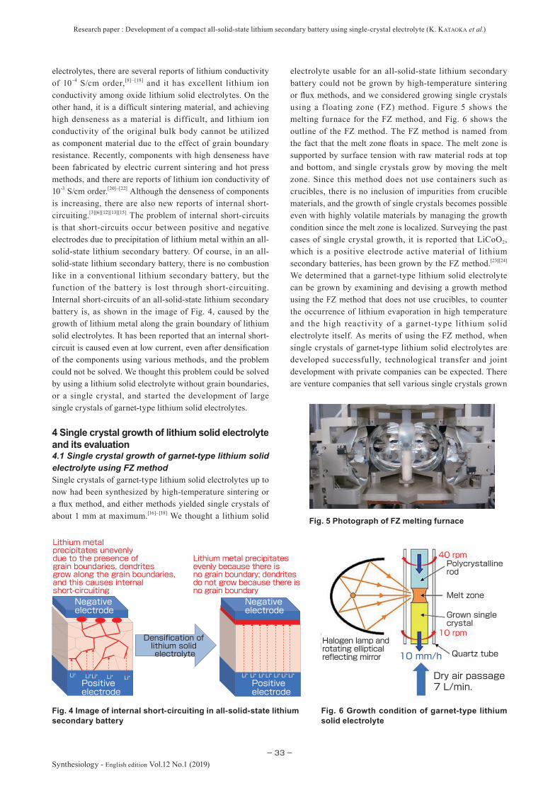
Research paper : Development of a compact all-solid-state lithium secondary battery using single-crystal electrolyte (K. KATAOKA et al.)
−33−Synthesiology - English edition Vol.12 No.1 (2019)
electrolytes, there are several reports of lithium conductivity of 10-4 S/cm order,[8]–[18] and it has excellent lithium ion conductivity among oxide lithium solid electrolytes. On the other hand, it is a difficult sintering material, and achieving high denseness as a material is difficult, and lithium ion conductivity of the original bulk body cannot be utilized as component material due to the effect of grain boundary resistance. Recently, components with high denseness have been fabricated by electric current sintering and hot press methods, and there are reports of lithium ion conductivity of 10-3 S/cm order.[20]–[22] Although the denseness of components is increasing, there are also new reports of internal short-circuiting.[3][6][12][13][15] The problem of internal short-circuits is that short-circuits occur between positive and negative electrodes due to precipitation of lithium metal within an all-solid-state lithium secondary battery. Of course, in an all-solid-state lithium secondary battery, there is no combustion like in a conventional lithium secondary battery, but the function of the battery is lost through short-circuiting. Internal short-circuits of an all-solid-state lithium secondary battery is, as shown in the image of Fig. 4, caused by the growth of lithium metal along the grain boundary of lithium solid electrolytes. It has been reported that an internal short-circuit is caused even at low current, even after densification of the components using various methods, and the problem could not be solved. We thought this problem could be solved by using a lithium solid electrolyte without grain boundaries, or a single crystal, and started the development of large single crystals of garnet-type lithium solid electrolytes.
4 Single crystal growth of lithium solid electrolyte and its evaluation4.1 Single crystal growth of garnet-type lithium solid electrolyte using FZ methodSingle crystals of garnet-type lithium solid electrolytes up to now had been synthesized by high-temperature sintering or a flux method, and either methods yielded single crystals of about 1 mm at maximum.[16]–[18] We thought a lithium solid
electrolyte usable for an all-solid-state lithium secondary battery could not be grown by high-temperature sintering or flux methods, and we considered growing single crystals using a f loating zone (FZ) method. Figure 5 shows the melting furnace for the FZ method, and Fig. 6 shows the outline of the FZ method. The FZ method is named from the fact that the melt zone floats in space. The melt zone is supported by surface tension with raw material rods at top and bottom, and single crystals grow by moving the melt zone. Since this method does not use containers such as crucibles, there is no inclusion of impurities from crucible materials, and the growth of single crystals becomes possible even with highly volatile materials by managing the growth condition since the melt zone is localized. Surveying the past cases of single crystal growth, it is reported that LiCoO2, which is a positive electrode active material of lithium secondary batteries, has been grown by the FZ method.[23][24] We determined that a garnet-type lithium solid electrolyte can be grown by examining and devising a growth method using the FZ method that does not use crucibles, to counter the occurrence of lithium evaporation in high temperature and the high reactivity of a garnet-type lithium solid electrolyte itself. As merits of using the FZ method, when single crystals of garnet-type lithium solid electrolytes are developed successfully, technological transfer and joint development with private companies can be expected. There are venture companies that sell various single crystals grown
Fig. 5 Photograph of FZ melting furnace
Fig. 6 Growth condition of garnet-type lithium solid electrolyte
Halogen lamp and rotating elliptical reflecting mirror
Polycrystalline rod
Melt zone
Grown single crystal
Quartz tube
Dry air passage7 L/min.
40 rpm
10 rpm
10 mm/h
Lithium metal precipitates evenly because there is no grain boundary; dendrites do not grow because there is no grain boundary
Lithium metal precipitates unevenly due to the presence of grain boundaries, dendrites grow along the grain boundaries, and this causes internal short-circuiting
Densification of lithium solid electrolyte
Negative electrode
Positive electrode
Negative electrode
Positive electrode
Li Li Li Li Li+ + + + + Li Li Li + Li Li LiLi+ + + + + +
Fig. 4 Image of internal short-circuiting in all-solid-state lithium secondary battery

Research paper : Development of a compact all-solid-state lithium secondary battery using single-crystal electrolyte (K. KATAOKA et al.)
−34−
Synthesiology - English edition Vol.12 No.1 (2019)
by the FZ method, and, as the FZ method is a so-called melting method, if single crystals can be grown, there are possibilities of improving and adapting large single crystal growth methods to industrial purpose for use in production by companies. There is a path for joint development with companies that already own facilities for growing and manufacturing single crystals. In fact, there is an example of pulling single crystals by the Czockralski (CZ) method using an iridium crucible in our published patent.[25]
In fact, we faced hardship when we started the actual investigation of single crystal growth of garnet-type lithium solid electrolytes. We did not know whether single crystals of garnet-type lithium solid electrolytes could be grown by a melting method. In addition, generally in single crystal growth by a melting method, one often considered issues while looking at phase diagrams, but in garnet-type lithium solid electrolytes, composition was complicated and there was no phase diagram. Therefore, in our R&D, various single crystal growth parameters were changed, analysis of the coagulated material was done after actual growth to achieve single crystal growth, and this was conducted by trial-and-error. Four years after starting the investigation of single crystal growth of garnet-type lithium solid electrolytes, we found the conditions for single crystal growth. Some of the characteristics of growth conditions are as follows: to excessively add about 1.2 times of lithium carbonate that will be the lithium source when preparing the raw material; to remove gas derived from evaporating lithium by passing about 7 L/min of dried air during single crystal growth; to remove air bubbles by rotating the supplied multi-crystal sample at about 40 rpm; and to keep the growth rate of single crystal growth to about 10 mm/h. Figure 6 shows the conditions of the growth in this study. Particularly, the part about the growth rate is interesting. Regarding single crystal growth using a general FZ method, the growth rate is kept at about 1–2 mm/h, but concerning garnet-type lithium solid electrolytes, single crystals could not be obtained at a generally-used growth rate, and were obtained at a fast rate of about 5–10 times. Using this method, we grew single crystals of garnet-type lithium solid electrolytes with various chemical compositions using the melting method for the first time in the world, and after organizing the patent application and the know-how, we published an academic paper.[26][27] In this paper, we describe the evaluation result of Li7-xLa3Zr2-xNbxO12 in which part of zirconium was substituted by niobium in a garnet-type lithium solid electrolyte as described in Reference [26]. Please refer to this reference for the experimental method and details of the result.
Figure 7 shows a single crystal rod of a garnet-type lithium solid electrolyte Li6.5La3Zr1.5Nb0.5O12 that was grown in this study, and a single crystal plate that was cut and surface polished. As shown in Fig. 7, we were able to grow a large single crystal with length of 8 cm and diameter of 8 mm for the fi rst time in the world.
4.2 Crystallographic and electrochemical evaluation of garnet-type lithium solid electrolyteThe fi rst evaluation conducted was on the correlation of lithium ion conductivity by substitution amount of Nb. Since higher lithium ion conductivity will be advantageous for battery action, this is the most important property. Looking at the correlation between the amount of Nb substitution and lithium ion conductivity using an AC impedance method, the lithium ion conductivity was maximum when Nb substitution was 0.5, and the value, as shown in Fig. 8, was 1.39 × 10⁻³ S/cm at 298 K. This value was higher than the conventionally reported value for a sintered body sample, and it is thought to be because there is no grain boundary effect. As a result of X-ray diffraction
Fig. 7 (a) Grown single crystal of garnet-type lithium solid electrolyte Li6.5La3Zr1.5Nb0.5O12; (b) cut and polished single crystal plate
(a)
(b)
Lithium ion conductivity1.39×10-3 S/cm @298 K
2000150010005000
-2000
-1500
-1000
-500
0
Z" (Ω)
Z' (Ω)
Fig. 8 Lithium ion conductivity and Nyquist plot at 298 K of garnet-type lithium solid electrolyte obtained by AC impedance measurement
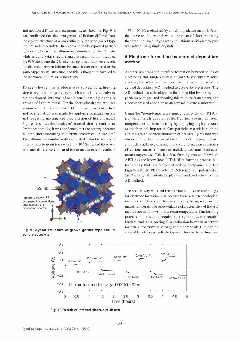
Research paper : Development of a compact all-solid-state lithium secondary battery using single-crystal electrolyte (K. KATAOKA et al.)
−35−Synthesiology - English edition Vol.12 No.1 (2019)
and neutron diffraction measurements, as shown in Fig. 9, it was confirmed that the arrangement of lithium differed from the crystal structure of a conventionally reported garnet-type lithium solid electrolyte. In a conventionally reported garnet-type crystal structure, lithium was dominant at the 24d site, while in our crystal structure analysis result, lithium occupied the 96h site where the 24d site was split into four. As a result, the distance between lithium became shorter compared to the garnet-type crystal structure, and this is thought to have led to the increased lithium ion conductivity.
To see whether the problem was solved by achieving single crystals for garnet-type lithium solid electrolytes, we conducted internal shor t-circuit tests by dendrite growth of lithium metal. For the short-circuit test, we used symmetric batteries to which lithium metal was attached, and confirmation was made by applying constant current and repeating melting and precipitation of lithium metal. Figure 10 shows the results of internal short-circuit tests. From these results, it was confirmed that the battery operated without short-circuiting at current density of 0.5 mA/cm2. The lithium ion conductivity calculated from the results of internal short-circuit tests was 1.0 × 10⁻³ S/cm, and there was no major difference compared to the measurement results of
1.39 × 10⁻³ S/cm obtained by an AC impedance method. From the above results, we believe the problem of short-circuiting that was the issue of garnet-type lithium solid electrolytes was solved using single crystals.
5 Electrode formation by aerosol deposition method
Another issue was the interface formation between solids of electrodes and single crystals of garnet-type lithium solid electrolytes. We attempted to solve this issue by using the aerosol deposition (AD) method to create the electrodes. The AD method is a technology for forming a film by mixing fine particles with gas, and shooting this mixture from a nozzle in a decompressed condition as an aerosol jet onto a substrate.
Using the “room-temperature impact consolidation (RTIC)” (in which high-density solidif ication occurs at room temperature without heating by applying high pressure or mechanical impact to fine particle materials such as ceramics with particle diameter of around 1 μm) that was discovered by Akedo, one of the authors of this paper, dense and highly adhesive ceramic films were formed on substrates of various materials such as metal, glass, and plastic, at room temperature. This is a film forming process for which AIST has the know-how.[28] This film forming process is a technology that is already utilized by companies and has high versatility. Please refer to Reference [28] published in Synthesiology for detailed explanation and past efforts on the AD method.
The reason why we used the AD method as the technology for electrode formation was because there was a technological merit as a technology that was already being used in the industrial world. The representative characteristics of the AD method are as follows: it is a room-temperature film forming process that does not require heating; it does not require binders such as a coating film; adhesion between substrate materials and films is strong; and a composite film can be created by utilizing multiple types of fine particles together. Fig. 9 Crystal structure of grown garnet-type lithium
solid electrolyte
Fig. 10 Result of internal short-circuit test
O
Zr, Nb
Li
La
Lithium is divided compared to conventional arrangement, and distance is shorter
Time (hours)
Voltage (V)
Lithium ion conductivity: 1.0×10⁻³ S/cm-0.3
-0.2
-0.1
0
0.1
0.2
0.3
54.543.532.521.510.50
0.1 mA/cm2
0.4 mA/cm20.3 mA/cm20.2 mA/cm20.5 mA/cm2
-0.1 mA/cm2
-0.4 mA/cm2-0.3 mA/cm2 -0.5 mA/cm2-0.2 mA/cm2
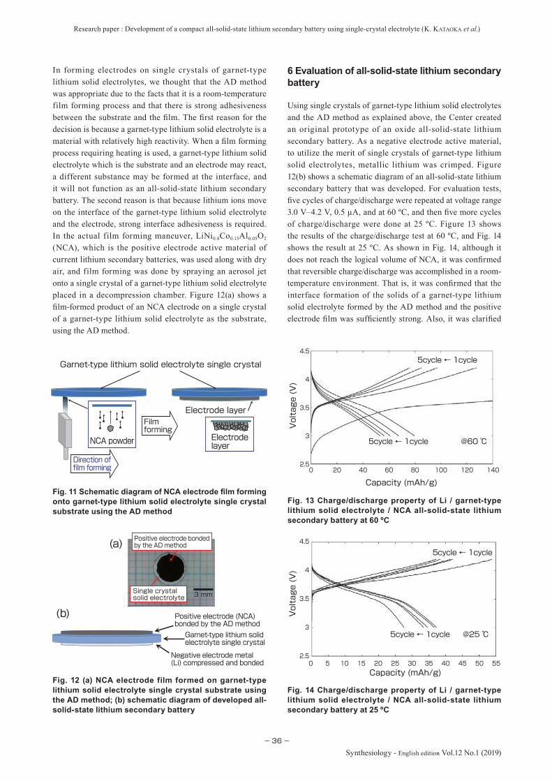
Research paper : Development of a compact all-solid-state lithium secondary battery using single-crystal electrolyte (K. KATAOKA et al.)
−36−
Synthesiology - English edition Vol.12 No.1 (2019)
In forming electrodes on single crystals of garnet-type lithium solid electrolytes, we thought that the AD method was appropriate due to the facts that it is a room-temperature film forming process and that there is strong adhesiveness between the substrate and the fi lm. The fi rst reason for the decision is because a garnet-type lithium solid electrolyte is a material with relatively high reactivity. When a fi lm forming process requiring heating is used, a garnet-type lithium solid electrolyte which is the substrate and an electrode may react, a different substance may be formed at the interface, and it will not function as an all-solid-state lithium secondary battery. The second reason is that because lithium ions move on the interface of the garnet-type lithium solid electrolyte and the electrode, strong interface adhesiveness is required. In the actual film forming maneuver, LiNi0.8Co0.15Al0.05O2
(NCA), which is the positive electrode active material of current lithium secondary batteries, was used along with dry air, and film forming was done by spraying an aerosol jet onto a single crystal of a garnet-type lithium solid electrolyte placed in a decompression chamber. Figure 12(a) shows a fi lm-formed product of an NCA electrode on a single crystal of a garnet-type lithium solid electrolyte as the substrate, using the AD method.
6 Evaluation of all-solid-state lithium secondary battery
Using single crystals of garnet-type lithium solid electrolytes and the AD method as explained above, the Center created an original prototype of an oxide all-solid-state lithium secondary battery. As a negative electrode active material, to utilize the merit of single crystals of garnet-type lithium solid electrolytes, metallic lithium was crimped. Figure 12(b) shows a schematic diagram of an all-solid-state lithium secondary battery that was developed. For evaluation tests, fi ve cycles of charge/discharge were repeated at voltage range 3.0 V–4.2 V, 0.5 μA, and at 60 ºC, and then fi ve more cycles of charge/discharge were done at 25 ºC. Figure 13 shows the results of the charge/discharge test at 60 ºC, and Fig. 14 shows the result at 25 ºC. As shown in Fig. 14, although it does not reach the logical volume of NCA, it was confi rmed that reversible charge/discharge was accomplished in a room-temperature environment. That is, it was confi rmed that the interface formation of the solids of a garnet-type lithium solid electrolyte formed by the AD method and the positive electrode fi lm was suffi ciently strong. Also, it was clarifi ed
Fig. 11 Schematic diagram of NCA electrode fi lm forming onto garnet-type lithium solid electrolyte single crystal substrate using the AD method
Fig. 12 (a) NCA electrode film formed on garnet-type lithium solid electrolyte single crystal substrate using the AD method; (b) schematic diagram of developed all-solid-state lithium secondary battery
3 mm
Positive electrode bonded by the AD method
Single crystal solid electrolyte
Negative electrode metal (Li) compressed and bonded
Garnet-type lithium solid electrolyte single crystal
Positive electrode (NCA) bonded by the AD method
(a)
(b)
Voltage (V)
Capacity (mAh/g)140120100806040200
2.5
3
3.5
4
4.5
5cycle ← 1cycle
5cycle ← 1cycle
@60 ℃
容量 (mAh/g)
電圧
(V)
Voltage (V)
Capacity (mAh/g)40200
2.5
3
3.5
4
4.5
5cycle ← 1cycle
5cycle ← 1cycle
@25 ℃
55504535302515105
Film forming
Electrode layer
Electrode layer
NCA powder
Direction of film forming
Garnet-type lithium solid electrolyte single crystal
Fig. 13 Charge/discharge property of Li / garnet-type lithium solid electrolyte / NCA all-solid-state lithium secondary battery at 60 ºC
Fig. 14 Charge/discharge property of Li / garnet-type lithium solid electrolyte / NCA all-solid-state lithium secondary battery at 25 ºC
Research paper : Development of a compact all-solid-state lithium secondary battery using single-crystal electrolyte (K. KATAOKA et al.)
−37−Synthesiology - English edition Vol.12 No.1 (2019)
that a single crystal of a garnet-type lithium solid electrolyte possessed the functions of an electrolyte solution and a separator as in conventional lithium secondary batteries.
7 Future prospects
There are still several issues for an oxide all-solid-state lithium secondary battery that is a prospective candidate for a next-generation secondary battery. In this research, it was found that the issues could be solved by combining single crystals of garnet-type lithium solid electrolytes and the AD method.
Single crystals of garnet-type lithium solid electrolytes, which we succeeded in growing for the first time in the world, has drawn interest of many research institutions and companies academically as well as indust r ially. Academically, there was hardly any research on garnet-type lithium solid electrolytes because a large bulk body of single crystals of lithium solid electrolytes did not exist. Currently, we are engaging in research on solid dispersal of lithium ions in a single crystal with solid ionics researchers, as well as conducting joint research with various institutions on the measurement of basic properties. Moreover, we are conducting research on the interface structure between solid electrolytes and electrodes to enable fabrication of an ideal electrode interface using single crystals. Industrially, we are conducting joint development with companies for single crystal growth toward achieving high quality, mass production, and large size, for single crystals of garnet-type lithium solid electrolytes.
The Center currently engages in research to clarify the mechanism with which single crystals of garnet-type lithium solid electrolytes are grown in a melting method, search for new garnet-type lithium solid electrolytes by element substitution to increase lithium ion conductivity, fabrication of a composite electrode film consisting of an electrode active substance and a lithium solid electrolyte, and achievement of a thick electrode film. While there are many issues to be overcome, we have succeeded in growing single crystals of high quality solid electrolytes, and we aim for practical realization of an all-solid-state lithium secondary battery by around 2030.
References
[1] J. B. Goodenough and Y. Kim: Challenges for rechargeable Li batteries, Chemistry of Materials, 22, 587–603 (2010).
[2] M. Armand and J. -M. Tarascon: Building better batteries, Nature, 451, 652–657 (2008).
[3] J. Jürgen and W. G. Zeier: A solid future for battery development, Nature Energy, 1, 16141 (2016).
[4] New Energy and Industrial Technology Development Organization (NEDO): Niji Denchi Gijutsu Kaihatsu Roadmap (Roadmap for Technological Development
of Secondary Battery) (2013), https://www.nedo.go.jp/content/100535728.pdf, accessed 2019-02-06 (in Japanese).
[5] Japan Patent Office, Ministry of Economy, Trade and Industry: Heisei 25 Nendo Tokkyo Shutsugan Gijutsu Doko Chosa, Ichiji-sedai Niji Denchi (First-Generation Secondary Batteries, FY 2013 Survey of Trend for Patent Filed Technologies) (2014), https://www.jpo.go.jp/shiryou/pdf/gidou-houkoku/25_ jisedai_battery.pdf, accessed 2019-02-06 (in Japanese).
[6] F. Aguesse, W. Manalastas, L. Buannic, J. M. Lopez Del Amo, G. Singh, A. Llordés and J. Kilner: Investigating the dendritic growth during full cell cycling of garnet electrolyte in direct contact with Li metal, Appl. Mater. Interfaces, 9 (4), 3808–3816 (2017).
[7] N. Kamaya, K. Homma, Y. Yamakawa, M. Hirayama, R. Kanno, M. Yonemura, T. Kamiyama, Y. Kato, S. Hama, K. Kawamoto and A. Mitsui: A lithium superionic conductor, Nature Materials, 10 (9), 682–686 (2011).
[8] Y. Kato, S. Hori, T. Saito, K. Suzuki, M. Hirayama, A. Mitsui, M. Yonemura, H. Iba and R. Kanno: High-power all-solid-state batteries using sulfide superionic conductors, Nature Energy, 1, 16030 (2016).
[9] C. J. Leo, G. V. Subba Rao and B. V. R. Chowdari: Fast ion conduction in the Li-analogues of Nasicon, Li1+X [(Ta1–xGex) A1] (PO4)3, J. Mater. Chem., 12, 1848–1853 (2002).
[10] Y. Inaguma, C. Liquan, M. Itoh, T. Nakamura, T. Uchida, H. Ikuta and M. Wakihara: High ionic conducivity in lithium lanthanum titanate, Solid State Communications, 86 (10), 689–693 (1993).
[11] S. Ohta, T. Kobayashi and T. Asaoka: High lithium ionic conductivity in the garnet-type oxide Li7-xLa3 (Zr2-x, Nbx) O12 (X=0-2), J. Power Sources, 196 (6), 3342–3345 (2011).
[12] K. Ishiguro, Y. Nakata, M. Matsui, I. Uechi, Y. Takeda, O. Yamamoto and N. Imanishi: Stability of Nb-doped cubic Li7La3Zr2O12 with lithium metal, J. Electrochem. Soc., 160 (10), A1690–A1693 (2013).
[13] H. Yamada, T. Ito and R. H. Basappa: Sintering mechanisms of high-performance garnet-type solid electrolyte densified by spark plasma sintering, Electrochimica Acta, 220, 648–656 (2016).
[14] K. Hayamizu, Y. Matsuda, M. Matsui and N. Imanishi: Lithium diffusion measurements on a garnet-type solid conductor Li6.6La3Zr1.6Ta0.4O12 by using a pulsed-gradient spin-echo NMR method, Solid State Nuclear Magnetic Resonance, 70, 21–27 (2015).
[15] C-L. Tsai, V. Roddat is, C. V. Chandran, Q. Ma, S. Uhlenbr uck, M. Bram, P. Heit jans and O. Guil lon: Li7La3Zr2O12 interface modif icat ion for Li dendr ite prevention, Appl. Mater. Interfaces, 8 (16), 10617–10626 (2016).
[16] R. Murugan, V. Thangadurai and W. Weppner: Fast lithium ion conduction in garnet-type Li7La3Zr2O12, Angew. Chem., Int. Ed., 46 (41), 7778–7781 (2007).
[17] J. Awaka, A. Takashima, K. Kataoka, N. Kijima, Y. Idemoto and J. Akimoto: Crystal structure of fast lithium-ionconducting cubic Li7La3Zr2O12, Chem. Lett., 40 (1), 60–62 (2011).
[18] C. A. Geiger, E. Alekseev, B. Lazic, M. Fisch, T. Armbruster, R. Langner, M. Fechtelkord, N. Kim, T. Pettke and W. Weppner: Crystal chemistry and stability of “Li7La3Zr2O12” garnet: a fast lithium-ion conductor, Inorg. Chem., 50 (3), 1089–1097 (2011).
[19] H. Hyooma and K. Hayashi: Crystal st r uctures of La3Li5M2O12 (M = Nb, Ta), Mat. Res. Bull., 23 (10), 1399–1407 (1988).

Research paper : Development of a compact all-solid-state lithium secondary battery using single-crystal electrolyte (K. KATAOKA et al.)
−38−
Synthesiology - English edition Vol.12 No.1 (2019)
completed the courses at the Department of Applied Fine Chemistry, Graduate School of Eng i ne e r i ng , Ok aya ma U n i v e r s i t y i n 19 9 6 ; e n g a g e d i n development of Ni-Cd and polymer bat ter ies at bat ter y manufactu r ing companies from 1996 to 2005; engaged in the development of high-output battery, improvement of battery manufacturing process, and launching of battery manufacturing process for a venture company from 2005 to 2014; became independent as a technical consultant from 2014; and currently, Visiting Researcher, AIST from 2017 to present. In this paper, was in charge of electrode fi lm formation by the AD method.
Hiroshi NAGATACompleted the master’s course at the Department of Applied Fine Chemistry, Graduate School of Engineering, Gifu University in 2004; received doctorate (Engineering) from the Gifu University hrough submission of dissertation in 2015; engaged in development of materials at chemical and automotive parts companies from 2004 to 2017; Research Fellow, AIST in 2017; and Senior Researcher, Energy Conversion and Storage Materials Team, Advanced Coating Technology Research Center, AIST to present. Specialty is secondary battery. In this paper, was in charge of fabrication of symmetric cell.
Hideaki NAGAIJoined Hokkaido National Industrial Research Institute (currently AIST), Agency of I ndus t r ia l Science and Technology, Ministry of International Trade and Industry in 1993; received doc tora t e ( Eng i nee r i ng) f rom t he Graduate School of Engineering, Kyushu University in 1993; and Senior Researcher, Energy Conversion and Storage Materials Team, Advanced Coating Technology Research Center, AIST from 2015 to present. Specialties are materials chemistry (ceramics and semiconductors) and thermophysical property measurement. In this paper, provided advice on fabrication of sintered rods for precursor test.
Junji AKIMOTOCompleted the doctor’s course at the Department of Mineralogy, Graduate School of Science, University of Tokyo in 1990; joined the National Chemical Laboratory for Industry, Agency for Indust r ial Science and Technology in 1990; and Team Leader, Energy Conversion and Storage Materials Team, Advanced Coating Technology Research Center, AIST from 2015 to present. Specialty is battery material oxides. In this paper, overviewed and supervised single crystal growth and electrochemical measurements.
Jun AKEDOGraduated from the Department of Applied Physics, Faculty of Science and Engineering, Waseda University in 1984; Assistant, Faculty of Science and Engineering, Waseda
[20] C. Bernuy-Lopez, W. Manalastas Jr., J. M. Lopez del Amo, A. Aguadero, F. Aguesse and J. A. Kilner: Atmosphere controlled processing of Ga-substituted garnets for high Li-ion conductivity ceramics, Chemistry of Materials, 26 (12), 3610–3617 (2014).
[21] D. Rettenwander, G. Redhammer, F. Preishuber-Pf lügl, L. Cheng, L. Miara, R. Wagner, A. Welzl, E. Suard, M. M. Doeff, M. Wilkening, J. Fleig and G. Amthauer: Structural and electrochemical consequences of Al and Ga cosubstitution in Li7La3Zr2O12 solid electrolytes, Chemistry of Materials, 28 (7), 2384-2392 (2016).
[22] L. Buannic, B. Orayech, J-M. López Del Amo J. Carrasco, N. A. Katcho, F. Aguesse, W. Manalastas, W. Zhang, J. Kilner and A. Llordés: Dual substitution strategy to enhance Li+ ionic conductivity in Li7La3Zr2O12 solid electrolyte, Chemistry of Materials, 29 (4), 1769–1778 (2017).
[23] L. Pinsard-Gaudart, V.-C. Ciomaga, O. Dragos, R. Guillot and N. Dragoe: Growth and characterization of LixCoO2
single crystals, Journal of Crystal Growth, 334 (1), 165–169 (2011).
[24] S. Uthayakumar, M. S. Pandiyan, D. G. Porter, M. J. Gutmann, R. Fan and J. P. Goff: Crystal growth and neutron diffraction studies of LixCoO2 bulk single crystals, Journal of Crystal Growth, 401, 169–172 (2014).
[25] K. Kataoka and J. Akimoto: Lithium-containing garnet crystal body, method for producing same, and all-solid-state lithium ion secondary battery, WO2016017769A1 (2015).
[26] K. Kataoka, H. Nagata and J. Akimoto: Lithium-ion conducting oxide single crystal as solid electrolyte for advanced lithium battery application, Scientifi c Reports, 8, Article No. 9965 (2018).
[27] K. Kataoka and J. Akimoto: High ionic conductor member of garnet-type oxide Li6.5La3Ta0.5O12, ChemElectroChem, 5, 2551–2557 (2018).
[28] J. Akedo, A. Nakano, J. Park, S. Baba and K. Ashida: The aerosol deposition method, Synthesiology English edition, 1 (2), 121–130 (2008).
Authors
Kunimitsu KATAOKAGraduated f rom the Depar tment of Applied Chemistry, Faculty of Science and Technology, Tokyo University of Science in 2004; completed the doctor’s course at the Department of Materials Sciences, Graduate School of Pure and Applied Sciences, University of Tsukuba in 2010; technical intern at AIST from 2004 to 2010; Research Fellow, Japan Society for the Promotion of Science from 2009 to 2010; Research Fellow, AIST in 2011; Limited-term Researcher, AIST from 2012; and currently, Senior Researcher, Energy Conversion and Storage Materials Team, Advanced Coating Technology Research Center, AIST to present. Specialty is crystallography. In this paper, was in charge of fabrication of sintered rod for precursor tests, growing single crystals, crystal structure analysis, electrochemical measurements, and writing up the paper.
Tadayoshi AKAOGraduated from the Department of Applied Fine Chemistry, Faculty of Engineering, Okayama University in 1994;
Research paper : Development of a compact all-solid-state lithium secondary battery using single-crystal electrolyte (K. KATAOKA et al.)
−39−Synthesiology - English edition Vol.12 No.1 (2019)
University during 1988~1991; joined the Mechanical Engineering Laboratory, Agency of I ndus t r ia l Science and Technology, Ministry of International Trade and Industry in 1991; and Group Leader, AIST in 2001. Director, Advanced Coating Technology Research Center, AIST since 2015. Doctor of Engineering. Was involved widely in development of materials and devices as well as research of optical magnetic recorder and optical sensor during university period, and worked on product development in a venture company that manufactured barcode readers. After joining Mechanical Engineering Laboratory, obtained idea for current research (AD method) from about 1994. Project Leader, NEDO Nanotechnology Program for five years since 2002. In this paper, overviewed and supervised the electrode fi lm formation by the AD method.
In general, the FZ method is used in crystal growth in places where a crucible cannot be used, and therefore, I feel there is a large gap in using it for large single crystal growth. If you have any clues on large multiple crystal growth, I think you should explain them to a degree that you are allowed to disclose, to make your claims more convincing.Answer (Kunimitsu Kataoka)
For achieving large crystals, we submitted evidence for large single crystal growth for garnet-type solid electrolytes by the Czoklalski (CZ) method using an iridium crucible in the published patent No. WO2016017769A1 for which we submitted a patent application. Based on this fact, I added the following text.
“In fact, there is an example of pulling single crystals by the Czockralski (CZ) method using an iridium crucible in our published patent.”Comment (Haruhiko Obara)
You write, “There is a difference in lithium arrangement between the crystal structure and the garnet-type lithium solid electrolyte that have been reported.” I think you should add some discussion about why you obtained such a crystal structure and how it affects the physical properties (such as conductivity).Answer (Kunimitsu Kataoka)
It is still unknown why the lithium arrangement changed. There is a possibility that we were able to confirm the original crystal structure through neutron diffraction that uses a single crystal with abundant diffraction data. Although this may be a problem of interpretation, the crystal structure obtained in this study has shorter distance between lithium compared to the conventional garnet-type crystal structure, and we think the ion conductivity increased as a result.
Therefore, I added the following text:“In a conventionally reported garnet-type crystal structure,
lithium was dominant at the 24d site, while in our crystal structure analysis result, lithium dominated the 96h site where the 24d site was split into four. As a result, the distance between lithium became shorter compared to the garnet-type crystal structure, and this is thought to have increased lithium ion conductivity.”Comment (Haruhiko Obara)
You write, “The problem of internal short-circuiting that was the issue of a garnet-type lithium solid electrolyte was solved by using a single crystal.” I think it is apparent that dendrites do not form because there is no grain boundary. Or, is there a basic mechanism that prevents dendrite growth when a single crystal is used?Answer (Kunimitsu Kataoka)
While it may seem obvious, this is not so clear and is a theme that is discussed to this day. There is a report that dendrite growth is a phenomenon that occurs regardless of the presence or absence of grain boundaries. However, in our research, we were able to prevent dendrites in the single crystal solid electrolyte. One factor is thought to be, as shown in Fig. 4, that the lithium metal precipitates homogenously since the surface of a single crystal is fl at. In fact, we confi rmed the phenomenon in which dendrites grew in single crystal solid electrolytes with rough surfaces and caused cracks.
3 Expectation for room-temperature bonding technology using AD methodComment (Haruhiko Obara)
You mention that the difficult issue of sintering integrally could be solved by room-temperature bonding technology using the AD method, but I cannot judge objectively whether the problems such as interface resistance and prevention of dispersal were actually solved. Do you have any evidence of the problems being solved?
Discussions with Reviewers
1 OverallComment (Haruhiko Obara, AIST)
This paper describes a highly original research on electrolytes using oxide single crystals and on electrode formation using the AD method for realization of all-solid-state lithium secondary batteries, and I think it is valuable as a paper for Synthesiology.Comment (Masahiko Makino, AIST)
I think the social demand for lithium secondary batteries will continue to increase in the future. It is expected that the technology developed in this paper will be the core as its usage expands to “IoT, wearables, and medical use” as aspired by the authors. This paper provides a detailed explanation on the hardships met in growing single crystals of garnet-type lithium solid electrolytes. I think it is appropriate as a paper of Synthesiology as it contains valuable information.
2 Expectation for oxide all-solid-state lithium secondary battery and issues for its R&DComment (Haruhiko Obara)
There is a possibility that the readers may become excessively concerned about the danger of sulfide all-solid-state lithium secondary batteries, on which many companies and research institutes are working, as you indicate the safety issues of sulfi de solid electrolytes that are your competing technology. I think you should reconsider the expression in the paper in making comparison with oxide batteries.Answer (Kunimitsu Kataoka)
I am not criticizing sulfide all-solid-state batteries. The issue of production of hydrogen sulfide gas when sulfide solid electrolytes react with water has been discussed for a long time in academic societies and papers, and is common knowledge among researchers and developers of all-solid-state lithium secondary batteries. However, with sulfide material large surface area and excellent interface formation can be achieved, and many institutes and companies are moving to realize sulfi de all-solid-state lithium secondary batteries fi rst. Since the generation of hydrogen sulfi de gas by water reaction cannot be avoided due to the nature of the material, institutes and companies are currently doing R&D by devising packaging. On the other hand, it has also become common knowledge among researchers and developers that there is no safety issue for oxide all-solid-state lithium secondary batteries.Comment (Haruhiko Obara)

Research paper : Development of a compact all-solid-state lithium secondary battery using single-crystal electrolyte (K. KATAOKA et al.)
−40−
Synthesiology - English edition Vol.12 No.1 (2019)
Answer (Kunimitsu Kataoka)Since the AD method is a film forming technology at room
temperature, it does not require a heating process. In the integral sintering method, heating is necessary to assure sintering. If heating is required, thermal dispersion occurs mutually at the interface of different solids, and there is high possibility of formation of different phases. On the other hand, the fact that the AD method is a technology of film forming at room temperature is evidence of being a solution above all else.
4 Expansion of use to “IoT, wearables, and medical use”Comment (Masahiko Makino)
For the “link between research goal and society,” you tend to concentrate on technical descriptions. How about addressing “high safety,” “long lifespan,” “environmental resistance,” or “Usage: IoT, wearables, medical use” that are listed in “Figure 2.
Overview of the current situation of lithium secondary battery and its future prospect” in this paper? I think there is particularly great expectations from society for secondary batteries of medical use.Answer (Kunimitsu Kataoka)
I added the following text.“Although it is still difficult to achieve high capacity and
high output with oxide all-solid-state lithium secondary batteries because a large surface area is needed, it is thought to excel in higher safety, longer lifespan, and better environmental resistance compared to sulfide all-solid-state lithium secondary batteries. It is thought that the goal should be the creation of small all-solid-state lithium secondary batteries that take advantage of such characteristics and can be used in the Internet of Things (IoT), wearable devices, and medical use.”
Commentary
−41−Synthesiology - English edition Vol.12 No.1 pp.41–50 (Aug. 2019)
land, the measures have still not reached 100 %. There were only three contaminants designated in the “Act to Prevent Soil Contamination on Agricultural Land,” and cadmium is regulated because of health effect to humans, while copper and arsenic are regulated because they cause growth disruption in plants. In December 2014, the standard value for cadmium in Japanese rice was revised from 1.0 mg/kg to 0.4 mg/kg that is the WHO standard. As the standard was raised, there is concern that issues would become apparent in certain regions in the future.
After WWII, pollution by volatile organic compounds (VOC) and heavy metals such as lead and hexavalent chromium became apparent accompanying the development of chemical and manufacturing industries. In the report published by the Geo-environmental Protection Center in 2000, there are about 930 thousand industrial businesses that have the possibility of causing pollution, the investigation cost will be about 2 trillion yen, and the decontamination cost is estimated to be about 11 trillion yen.[2] In Japan, the laws pertaining to soil contamination in the urban area is lagging 20 years behind the American Comprehensive Environmental Response, Compensation, and Liability Act (also known as Super Fund Law, established in 1980), but the “Soil Contamination Countermeasures Act” (hereinafter, Countermeasures Act) was established in 2003. In this law, the contaminants are categorized into category 1, 2, and 3 designated hazardous substances, and these refer to VOCs, heavy metals,Term 1 and agrichemicals and PCB, respectively. After undergoing several amendments, as of now, there are 12, 9, and 5 substances that are designated as category 1, type 2, and type 3 designated hazardous substances (total
1 Introduction
Soil and groundwater contamination is an “old and new environmental problem.” In the past, there was the “Ashio Copper Mine Pollution” incidence, and recently, there are the radioactive contamination induced by the Fukushima Daiichi Nuclear Power Plant accident and the soil contamination at the Toyosu Market site. Soil and groundwater contamination can be called a “negative legacy” of various industrial activities, and it changes according to periods and industrial structures. Moreover, regulations also change according to policies and cultural evolution.
In Japan, mining and refining industries developed rapidly with the growth of heavy industries in the latter half of the 19th century, and pollution of agricultural land by mine drainage became serious social issues. The incident in which agricultural land along the Watarase River was polluted in the late 1880s (known as Ashio Copper Mine Pollution) became the origin of pollution issues in Japan. Beginning with the itai-itai disease (cadmium poisoning) that occurred in the Jintsu River basin of Toyama prefecture in 1968, the “Act to Prevent Soil Contamination on Agricultural Land” went into effect in 1970. According to the report[1] published by the Environmental Management Bureau, Ministry of the Environment in December 2016, the surface area of land, from which hazardous material surpassing the environmental standard set by the law was detected, was 7,592 ha as of the end of FY 2015, and the countermeasures were completed for about 92.7 % of the contaminated land. As it can be seen, even after conducting countermeasures for over 50 years after the discovery of soil contamination in agricultural
—An interdisciplinary approach—
Feasible countermeasures are needed to address soil and groundwater contamination problems, because of its impact on human health and socioeconomic activities. Soil and groundwater contamination is a complex issue that requires an interdisciplinary effort involving research into contaminants, their practical removal, and social implementation. This paper discusses several areas of research that the author has been involved in this regard.
Challenges of solving the problem of soil and groundwater contamination
Keywords : Soil and groundwater contamination, remediation technologies, environmental regulation, sustainable development
[Translation from Synthesiology, Vol.12, No.1, p.39–47 (2019)]
Ming ZHANG
Research Institute for Geo-Resources and Environment, GSJ, AIST Tsukuba Central 7, 1-1-1 Higashi, Tsukuba 305-8567, JapanE-mail: [email protected]
Original manuscript received January 6, 2019, Revisions received January 22, 2019, Accepted January 24, 2019

Commentary : Challenges of solving the problem of soil and groundwater contamination (M. ZHANG)
−42−
Synthesiology - English edition Vol.12 No.1 (2019)
26 substances) under the Countermeasures Act. Note that the designated hazardous substances consist of only a very small portion of about 65,000 chemical substances that are used in Japan. Also note that the current environmental regulations of Japan are not based on risks but are uniform environmental standard values.
With the enforcement of the Countermeasures Act, cases of investigation and countermeasures for soil contamination have increased every year in Japan. According to the latest report published by the Environmental Management Bureau, Ministry of the Environment, there are about 1200 cases of investigation and countermeasures based on the regulations, and there may be several thousand more cases if the voluntary measures by private companies are included.[3] However, there are potentially hundreds of thousands of contaminated sites, and several thousand cases is only 1 %. It is quite clear that a long road lies in front of us in solving the problems of soil and groundwater contamination.
In this paper, we present the diversity and complexity of soil and groundwater contamination problems, describe the elemental technologies needed to rationally solve the problems of soil and groundwater contamination, construct and discuss the scenario for implementation in society, and introduce some research cases in which the author was involved.
2 Diversity and complexity of soil and groundwater contamination
There are three categories and 26 substances that are designated as hazardous substances (contaminants) in the Countermeasures Act, but there are numerous other toxic and/or harzarous substances that may actually affect human health. In Europe, the contaminants are categorized into heavy metals, aromatic hydrocarbons (BTEX = benzene, toluene, ethylbenzene, trimethylbenzenes and the three xylene isomers), organochlor ine compounds (CHC = chlorinated hydrocarbons), polycyclic aromatic hydrocarbon (PAH), and mineral oils.[4] In Japan, although the “Oil Contamination Countermeasure Guideline” was published, there is no regulation by law.[5] There are several isomers of BTEX, CHC, and PAH, but the VOCs designated in the Countermeasures Act includes only some of BTEX and CHC.
The Fukushima Daiichi Nuclear Power Plant accident was induced by the Great East Japan Earthquake and Tsunami of March 11, 2011, and contamination by radioactive substances occurred over a wide area. To take measures against this urgent issue, the “Act on Special Measures Concerning the Handling of Environment Pollution by Radioactive Materials Discharged by the Nuclear Power Station Accident Associated with the Tohoku District-Off the Pacific Ocean Earthquake That Occurred on March 11, 2011” was adopted
in August 30, 2011 and went into effect on January 1, 2012. That is, the contamination by radioactive materials is out of the range of the Countermeasures Act.
The revised “Indust r ial Safety and Health Act” was implemented on June 1, 2016, and the risk assessment of chemical substances became an obligation. In this revision, the businesses, which manufacture or handle 640 target chemical substances for which certain levels of danger and hazards have been confi rmed, are obligated to conduct risk assessment, regardless of the business type or size. Also, for the water standard based on the Waterworks Law, other than the 51 regulated items, 26 items for which water management goals are set and 47 items that should be investigated (total 124 items) are designated. As it can be seen, there are only a few chemical substances regulated by the Countermeasures Act. This is because the soil contamination problem is extremely complex, the investigation and countermeasures are not easy, and realistically it is diff icult to enforce strict regulations.[6] At this point, there are possibilities that the substances that are not currently regulated by the Countermeasures Act may become regulated in the future, and in some cases, they may become social issues. In fact, chloroethylene (vinyl chloride) was added to the list of regulated substances under the Countermeasures Act in April 2017, and land that was not contaminated turned into contaminated land according to the laws, and there were cases in which land became unsellable or non-developable.
In addition to the diversity of the contaminants, the diversity, heterogeneity, and anisotropy of soils, as well as strong adsorption between organic substances and clay minerals make the soil contamination problem extremely complex. Also, for some contaminants, pollution may occur in chain reaction due to material circulation in nature (Fig. 1). In the Basic Environment Law, soil contamination is positioned as one of the “seven major types of pollution” including air pollution, water pollution, noise, vibration, ground
Fig. 1 Interactions among air, water and soil pollutions due to material circulation
Material circulation
DecompositionDischarge
IntakeEnrichment
AdsorptionDeposition
LeachingDiffusion
DepositionPrecipitation
VolatilizationDiffusion
DepositionPrecipitation
VolatilizationDiffusion
Living organism
WaterSoilSediments
Air
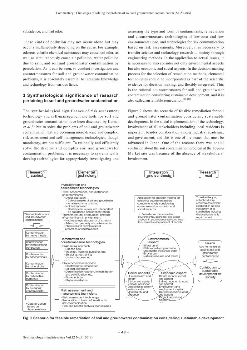
Commentary : Challenges of solving the problem of soil and groundwater contamination (M. ZHANG)
−43−Synthesiology - English edition Vol.12 No.1 (2019)
subsidence, and bad odor.
These kinds of pollution may not occur alone but may occur simultaneously depending on the cause. For example, odorous volatile chemical substances may cause bad odor, as well as simultaneously cause air pollution, water pollution due to rain, and soil and groundwater contamination by percolation. As it can be seen, to conduct investigation and countermeasures for soil and groundwater contamination problems, it is absolutely essential to integrate knowledge and technology from various fi elds.
3 Synthesiological significance of research pertaining to soil and groundwater contamination
The synthesiological signif icance of r isk assessment technology and self-management methods for soil and groundwater contamination have been discussed by Komai et al.,[7] but to solve the problems of soil and groundwater contamination that are becoming more diverse and complex, risk assessment and self-management technologies, though mandatory, are not sufficient. To rationally and efficiently solve the diverse and complex soil and groundwater contamination problems, it is necessary to systematically develop technologies for appropriately investigating and
assessing the type and form of contaminants, remediation and countermeasure technologies of low cost and low environmental load, and technologies for risk communication based on risk assessments. Moreover, it is necessary to transfer science and technology research to society through engineering methods. In the application to actual issues, it is necessary to also consider not only environmental aspects but also economic and social aspects. In the decision-making process for the selection of remediation methods, elemental technologies should be incorporated as part of the scientifi c evidence for decision making, and fl exibly integrated. This is the rational countermeasures for soil and groundwater contamination considering sustainable development, and it is also called sustainable remediation.[8]–[10]
Figure 2 shows the scenario of feasible remediation for soil and groundwater contamination considering sustainable development. In the social implementation of the technology, involvement of all stakeholders including local residents is important, besides collaboration among industry, academia, and government, and this is one of the issues that must be advanced in Japan. One of the reasons there was social confusion about the soil contamination problem at the Toyosu Market site was because of the absence of stakeholders’ involvement.
Fig. 2 Scenario for feasible remediation of soil and groundwater contamination considering sustainable development
☆
*Categorization based on Japanese laws
・Direct economic cost and benefit・Indirect economic cost and benefit・Employment and employment capital・Derived economic cost and benefit・Project period and flexibility・・・
Economic aspect・Human health and safety・Ethics and equity・Vicinage and region・Contribution to society and community・Uncertainty and evidence・・・
Social aspects
・Effect on air・Status of soil and groundwater・Groundwater and surface water・Ecosystem・Natural resource and waste・・・
Environmental aspect
Integration and synthesis
Research goal
Elemental technology
Research subject
・・・
Contamination by emerging contaminants
Contamination by mineral oils
Contamination by radioactive materials
Contamination by agrichemicals
Contamination by volatile organic compounds
Contamination by heavy metals
・Risk assessment technology・Preparation of basic information for risk communication・Risk and benefit analysis technologies・・・
Risk assessment and management technology
・Engineering approach ・Dig and haul ・Washing, flushing, pumping, etc. ・Shielding, restraining contact/access, etc. ・・・・Physicochemical approach ・Electrokinetic remediation ・Solvent extraction ・Detoxification reaction, immobilization and solidification, etc. ・Bioremediation ・Phytoremediation ・・・
Remediation and countermeasure technologies
・Type, concentration, and distribution of contaminants ・Direct approach ・Collect samples of soil and groundwater ・Analyze on site or at lab ・Indirect approach ・Geophysical survey etc. (dependent on substance and concentration)・Transfer, natural attenuation, and fate of contaminant in environment ・Hydrogeological property of stratum ・Adsorption property of contaminants ・Chemical and microbiological properties of contaminants・・・
Investigation and assessment technologies
*Various kinds of soil and groundwater contamination
Application to decision making on selecting countermeasures comprehensively considering environmental, economic, and social aspects
☆: Remediation that considers environmental, economic, and social aspects in good balance will contribute to sustainable development of society
To realize the goal, not only industry-academia-government collaboration but also involvement of all stakeholders including the local residents is very important.
Feasible countermeasures against soil and groundwater contamination
Contribution to sustainable development of
society
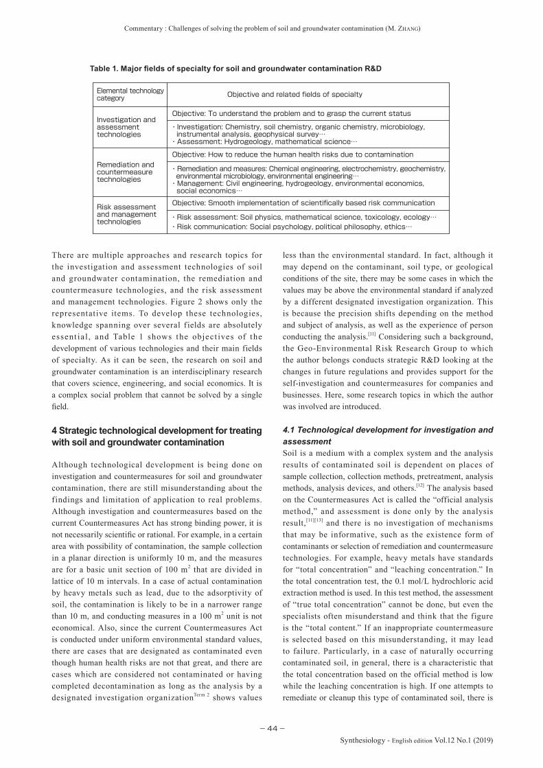
Commentary : Challenges of solving the problem of soil and groundwater contamination (M. ZHANG)
−44−
Synthesiology - English edition Vol.12 No.1 (2019)
There are multiple approaches and research topics for the investigation and assessment technologies of soil and groundwater contamination, the remediation and countermeasure technologies, and the risk assessment and management technologies. Figure 2 shows only the representative items. To develop these technologies, knowledge spanning over several f ields are absolutely essent ia l , and Table 1 shows the object ives of the development of various technologies and their main fields of specialty. As it can be seen, the research on soil and groundwater contamination is an interdisciplinary research that covers science, engineering, and social economics. It is a complex social problem that cannot be solved by a single field.
4 Strategic technological development for treating with soil and groundwater contamination
Although technological development is being done on investigation and countermeasures for soil and groundwater contamination, there are still misunderstanding about the findings and limitation of application to real problems. Although investigation and countermeasures based on the current Countermeasures Act has strong binding power, it is not necessarily scientific or rational. For example, in a certain area with possibility of contamination, the sample collection in a planar direction is uniformly 10 m, and the measures are for a basic unit section of 100 m2 that are divided in lattice of 10 m intervals. In a case of actual contamination by heavy metals such as lead, due to the adsorptivity of soil, the contamination is likely to be in a narrower range than 10 m, and conducting measures in a 100 m2 unit is not economical. Also, since the current Countermeasures Act is conducted under uniform environmental standard values, there are cases that are designated as contaminated even though human health risks are not that great, and there are cases which are considered not contaminated or having completed decontamination as long as the analysis by a designated investigation organizationTerm 2 shows values
less than the environmental standard. In fact, although it may depend on the contaminant, soil type, or geological conditions of the site, there may be some cases in which the values may be above the environmental standard if analyzed by a different designated investigation organization. This is because the precision shifts depending on the method and subject of analysis, as well as the experience of person conducting the analysis.[11] Considering such a background, the Geo-Environmental Risk Research Group to which the author belongs conducts strategic R&D looking at the changes in future regulations and provides support for the self-investigation and countermeasures for companies and businesses. Here, some research topics in which the author was involved are introduced.
4.1 Technological development for investigation and assessmentSoil is a medium with a complex system and the analysis results of contaminated soil is dependent on places of sample collection, collection methods, pretreatment, analysis methods, analysis devices, and others.[12] The analysis based on the Countermeasures Act is called the “official analysis method,” and assessment is done only by the analysis result,[11][13] and there is no investigation of mechanisms that may be informative, such as the existence form of contaminants or selection of remediation and countermeasure technologies. For example, heavy metals have standards for “total concentration” and “leaching concentration.” In the total concentration test, the 0.1 mol/L hydrochloric acid extraction method is used. In this test method, the assessment of “true total concentration” cannot be done, but even the specialists often misunderstand and think that the figure is the “total content.” If an inappropriate countermeasure is selected based on this misunderstanding, it may lead to failure. Particularly, in a case of naturally occurring contaminated soil, in general, there is a characteristic that the total concentration based on the official method is low while the leaching concentration is high. If one attempts to remediate or cleanup this type of contaminated soil, there is
・Risk assessment: Soil physics, mathematical science, toxicology, ecology…・Risk communication: Social psychology, political philosophy, ethics…
Objective: Smooth implementation of scientifically based risk communicationRisk assessment and management technologies
・Remediation and measures: Chemical engineering, electrochemistry, geochemistry, environmental microbiology, environmental engineering…・Management: Civil engineering, hydrogeology, environmental economics, social economics…
Objective: How to reduce the human health risks due to contaminationRemediation and countermeasure technologies
・Investigation: Chemistry, soil chemistry, organic chemistry, microbiology, instrumental analysis, geophysical survey…・Assessment: Hydrogeology, mathematical science…
Objective: To understand the problem and to grasp the current statusInvestigation and assessment technologies
Objective and related fields of specialtyElemental technology category
Table 1. Major fields of specialty for soil and groundwater contamination R&D

Commentary : Challenges of solving the problem of soil and groundwater contamination (M. ZHANG)
−45−Synthesiology - English edition Vol.12 No.1 (2019)
a possibility that the value will not become lower than the environmental standard even after repeated washing. This is because the true total concentration is much higher than the analysis value obtained by the official analysis method.
To solve such a problem, the author and research collaborators are developing an assessment method looking at the existence form of contaminants. For example for a lead-contaminated soil that exists frequently due to natural causes, we clarified the existence form of lead-containing minerals using sedimentation classification and X-ray diffraction analysis, and established a simple quantitative analysis method.[14] Samples that were classified by particle diameter were subject to whole rock chemical analysis using a portable X-ray fluorescence (XRF) analyzer (Niton XL 3t-900S-M, Thermo Fisher Scientific Inc.). Mixed samples in which the weight ratios of each sample and the standard sample (metal silicon) were 1:1 were made, each mineral phase was identified, and simple quantitative analysis of the phases was conducted using an X-ray powder diffractometer (Smart Lab, Rigaku Corporation). For the quantitative analysis of the mineral phase in the sample, the integral strength of the diffraction peak of the standard sample was set at 50, and the relative amount of an unknown sample was calculated. When this was used to assess two samples collected at a certain site, one sample showed a positive correlation between lead concentration and particle size, and a good correlation with galena content. In the other sample, there was a negative correlation between lead concentration and particle size, and a positive correlation with alunite content (Fig. 3).[14] In the field of soil contamination, there is a method called particle size classified washing, and it is one of the frequently used cleanup methods. This method is used under the assumption that a contaminant is adsorbed by fine particles which contains many clay substances and have a large specific surface area. However, this assumption is not necessarily valid in the actual contaminated soil. As can be seen, the correlation between particle size of the contaminant and mineral content can be used for deciding which cleanup or countermeasure can be used, as well as the concentration of
the contaminants.
4.2 Technological development for remediation and countermeasureAs technologies for remediation and countermeasure, there are an engineering approach and a physico-chemical approach, and there are several methods in each approach (Fig. 2). However, due to reliability, remediation methods with high cost such as dig and haul were conducted for almost all case studies that were reported.[3] Although 86 bil l ion yen was spent for the remediat ion of the Toyosu Market site, it has been reported that complete decontamination was not ultimately possible. Therefore, the development of remediation technology of low cost and low environmental load is a research topic with high priority. The Geo-Environmental Risk Research Group is actively working on the remediation technology utilizing mineral materials[15]–[17] and environmental microorganisms.[18]–[20] The former can be used for adsorption and immobilization of heavy metals such as arsenic, and the latter can be used for the decomposition of VOCs. As a point to be added, adsorption is not merely the change in contaminant concentration, but also involves detailed assessment of the environmental stability of spent adsorption material[15] and the soil type and effect of silicic acid in the soil.[16][17] In this research, we conducted systematic evaluation of the main soil types as follows: acidic andosol that is rich in organic components; weak acidic yellow-brown forest soil; neutral Kanuma soil that contains high quantity of allophane (clay made of hydrophilic aluminosilicate with low crystallization and is widely distributed in the volcanic ash zone); alkaline river sand with high silica content; and mountain sand with high iron content. For the decomposition of VOCs using microorganisms, we conducted decomposition tests under conditions replicating combined pollution that occurs at actual contamination sites rather than on a single contaminant.[18][19] Moreover, in decomposition of combined pollution, we identified which microorganism contributed to the decomposition of which contaminant using stable isotope
0
10000
20000
30000
40000
0 500 1000 1500 2000
粒子サイズ(μm)
0
1
2
3
4
5
0 10000 20000 30000 40000
鉛の濃度(ppm)
△Sample A: Galena× Sample B: Alunite
Lead concentration (ppm)
Mineral content (%)
Particle size (µm) Lead concentration (ppm)
◇ Sample A○ Sample B
Fig. 3 Relationships among lead concentration, particle size, and mineral content in naturally occurring contaminated soil samples
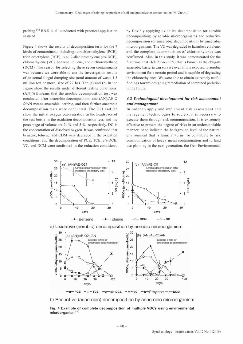
Commentary : Challenges of solving the problem of soil and groundwater contamination (M. ZHANG)
−46−
Synthesiology - English edition Vol.12 No.1 (2019)
probing.[20] R&D is all conducted with practical application in mind.
Figure 4 shows the results of decomposition tests for the 7 kinds of contaminants including tetrachloroethylene (PCE), trichloroethylene (TCE), cis-1,2-dichloroethylene (cis-DCE), chloroethylene (VC), benzene, toluene, and dichloromethane (DCM). The reason for selecting these seven contaminants was because we were able to use the investigation results of an actual illegal dumping site (total amount of waste 1.5 million ton or more, size of 27 ha). The (a) and (b) in the figure show the results under different testing conditions. (AN)/AE means that the aerobic decomposition test was conducted after anaerobic decomposition, and (AN)/AE-
/AN means anaerobic, aerobic, and then further anaerobic decomposition tests were conducted. The O21 and O5 show the initial oxygen concentration in the headspace of the test bottle in the oxidation decomposition test, and the percentage of volume are 21 % and 5 %, respectively. DO is the concentration of dissolved oxygen. It was confi rmed that benzene, toluene, and CDM were degraded in the oxidation conditions, and the decomposition of PCE, TCE, cis-DCE, VC, and DCM were confi rmed in the reduction conditions,
by f lexibly applying oxidative decomposition (or aerobic decomposition) by aerobic microorganisms and reductive decomposition (or anaerobic decomposition) by anaerobic microorganisms. The VC was degraded to harmless ethylene, and the complete decomposition of chloroethylenes was confirmed. Also, in this study, it was demonstrated for the fi rst time, that Dehalococcoides that is known as the obligate anaerobic bacteria can survive even if it is exposed to aerobic environment for a certain period and is capable of degrading the chloroethylenes. We were able to obtain extremely useful fi ndings toward designing remediation of combined pollution in the future.
4.3 Technological development for risk assessment and managementIn order to apply and implement r isk assessment and management technologies to society, it is necessary to execute them through risk communication. It is extremely effective to present the degree of risks in an understandable manner, or to indicate the background level of the natural environment that is familiar to us. To contribute to risk communication of heavy metal contamination and to land use planning in the next generation, the Geo-Environmental
Fig. 4 Example of complete decomposition of multiple VOCs using environmental microorganism[19]
a) Oxidative (aerobic) decomposition by aerobic microorganism
b) Reductive (anaerobic) decomposition by anaerobic microorganism
Ethylene
TolueneBenzene
Second circle of anaerobic decomposition
Second circle of anaerobic decomposition
Aerobic decomposition after anaerobic preliminary test
Aerobic decomposition after anaerobic preliminary test

Commentary : Challenges of solving the problem of soil and groundwater contamination (M. ZHANG)
−47−Synthesiology - English edition Vol.12 No.1 (2019)
Risk Research Group compiled the “Geochemical and Risk Assessment Map of Subsurface Soils” which considers the total concentration, leaching concentration of various elements including heavy metals in the subsurface soil, as well as the local industrial structure and the lifestyle of residents. The compilation of these maps was completed for the prefectures of Miyagi, Toyama, Tottori, Ibaraki, and Kochi, and the maps are available on the web (https://unit.aist.go.jp/georesenv/georisk/japanese/home/home_map.html). As an example, Fig. 5 shows the risk assessment map of Kochi Prefecture for total concentration of chromium, leaching concentration with hydrochloric acid, leaching concentration with water, and human health risks on the GoogleEarth map. It is apparent that even if the total concentration is high, the leaching concentration is not necessarily high, and even in points where leaching concentration surpassed the environmental standard, human health risks considering the local industrial structure and residents’ lifestyle is extremely low. Currently, we are working on investigation and analysis for the compilation and publication of the Shikoku region, and we hope to cover the whole country in the future.
4.4 Development of decision-making assistant tool for sustainable remediationSustainable remediation is not a remediation technology itself, but is a decision making process for selecting the optimal remediation method considering comprehensively social and economic aspects as well as the environmental aspect in the countermeasures for soil and groundwater contamination.[8] Sustainable remediation is not a remediation technology based on uniform environmental standards, but is an improved version of green remediation proposed by the Environmental Protection Agency (EPA) of USA and the American Society for Testing and Materials (ASTM).[21] Recently, the framework
for standards for sustainable remediation has been published by the International Organization for Standardization (ISO),[10] and the author was involved in the standardization as one of the reviewers in the process. At this point, although the framework of sustainable remediation was proposed, there is no established tool for social implementation. Therefore, the author collaborated with researchers of and outside AIST to develop a tool based on a hierarchical decision-making method (Fig. 6).[22]
This is one of the decision-making processes through problem solving in which the subjective judgement and systems approach are integrated to analyze a problem. It is called the hierarchical decision process.[23] By using this system, it becomes possible to provide an objective and neutral result, by entering and tallying relative points for subjective opinions of parties concerned in different positions, in the process of decision making by stakeholders. This enables consensus building, and decision making can be done smoothly. We are developing this tool aiming at opening it to the public.
5 Future issues and perspective
While the seriousness of soil contamination problem is growing in the developing countries, it is still a social issue that must be faced in developed countries such as Japan. However, in addition to the diversity of contaminants, the soil contamination problem is extremely complex due to the heterogeneity and isotropy of the geological formations as well as diversity of the soil. Therefore, in order to efficiently and effectively solve the soil contamination problem, development of knowledge and elemental technologies of a single field is insufficient. Other than development of
Fig. 5 Assessment of chromium in “Geochemical and Risk Assessment Map of Subsurface Soils” for Kochi Prefecture
Distribution map of total concentration for Cr
Distribution map of leaching concentration of Cr with hydrochloric acid
Distribution map of leaching concentration of Cr with water
Risk assessment map on human health by Cr

Commentary : Challenges of solving the problem of soil and groundwater contamination (M. ZHANG)
−48−
Synthesiology - English edition Vol.12 No.1 (2019)
realizable technology by integration of several fields, it is necessary to integrate and synthesize f lexibly. Also, it is absolutely essential to pursue more effective regulations and management.
Since large amount of expenditure is often necessary for soil contamination measures, the construction of a countermeasure and management system that considers the economic and social aspects together with environmental aspects is extremely important. Also, it is thought that the establishment of a countermeasure and management system for soil contamination that enables sustainable development and progress, as well as application of countermeasure technology based on risk assessment and selection of countermeasure technology considering the use of land are important. It is possible to integrate various elemental technologies in constructing such a system.
Although there may be par ts that are insuff icient or misleading due to the limitation of time and print space as well as the author’s lack of knowledge or wisdom, the author hopes to contribute as much as possible not only to the soil contamination problem in Japan but also to international cooperation and collaboration for environmental problems, through deepening discussions in the future.
EN1 EN2 EN3 EN4 EN5 EC1 EC2 EC3 EC4 EC5 SO1 SO2 SO3 SO4 SO5
Society (SO)
Countermeasure 3Countermeasure 1 Countermeasure 2
Economy (EC)
Comprehensive assessment / Decision
Environment (EN)
Fig. 6 Example of hierarchy in decision making process for sustainable remediation[22]
Terminologies
Term 1. Heavy metals: Heavy metals include metals with relatively large specific gravity, generally of over 4–5. In the laws and soil contamination field, cyanides, f luorine and its compounds, and boron and its compounds that cause health damage to humans just like the conventional heavy metals such as lead and mercury are included.
Term 2. Designated investigation organization: Organization that is set by law to conduct appropriate investigations
in carrying out specific investigations based on the governing laws. In Articles 3 and 4 of the Countermeasures Act (2002), the investigation must be carried out by an entity designated by the Minister of the Environment. In this case, the entity designated by the Minister of the Environment is the designated investigation organization.
References
[1] Environmental Management Bureau, Ministry of the Environment: Heisei 27 nendo noyochi dojo osen boushi-ho no shiko jokyo (Enforcement status of the Soil Contamination Countermeasures Act in agricultural land for FY 2015) (2016) (in Japanese).
[2] Geo-environmental Protection Center: Waga kuni ni okeru dojo osen taisaku hiyo no suitei (Estimate of the soil contamination countermeasure cost in Japan) (2000) (in Japanese).
[3] Environmental Management Bureau, Ministry of the Environment: Heisei 28 nendo dojo osen taisaku-ho no shiko jokyo oyobi dojo osen chosa taisaku jirei to ni kansuru chosa kekka (Enforcement status of the Soil Contamination Countermeasures Act and survey results pertaining to investigations of soil contamination and countermeasure case studies for FY 2016) (2018) (in Japanese).
[4] European Environment Agency (EEA): Main contaminants at industrial and commercial sites affecting soil in Europe as % of total, http://www.eea.europa.eu/data-and-maps/figures/main-contaminants-at-industrial-and-commercial-sitesaffecting-soil-in-europe-as-of-total/csi15_fig02.eps/image_large, accessed 2019-01-03.
[5] Technical Committee for Soil Contamination Technology and Standards, Soil and Agrichemical Group, Central Environmental Council: Abura osen taisaku guideline— Koyurui o fukumu dojo ni kiin suru yushu yumaku mondai eno tochi shoyusha to niyoru taio no kangae-kata (Oil pollution countermeasure guideline—Views on measures by land owners etc. against oil smell and oil film originating from soil containing mineral oils, etc.) (2006) (in Japanese).
[6] M. Z ha ng: Dojo ose n t a i s a k u t o se ido no kongo (Countermeasures for soil contamination and future
Commentary : Challenges of solving the problem of soil and groundwater contamination (M. ZHANG)
−49−Synthesiology - English edition Vol.12 No.1 (2019)
perspective), Kankyo Kanri Taisaku To Seido No Kongo Koen Yoshishu (Proceedings of Special Seminar on Environmental Management and Future of the Problem), Organizat ion for Research and Communicat ion of Environmental Risk of Chemicals, 65–74 (2017) (in Japanese).
[7] T. Komai, Y. Kawabe, J. Hara, Y. Sakamoto and H. Sugita: Development of a risk assessment system for soil contamination and the application to the social system— Processes in Synthesiology for practicing an advanced environmental risk management, Synthesiology, 1 (4), 276–286 (2008) (in Japanese) [Synthesiology English edition, 1 (4), 251–262 (2009)].
[8] M. Zhang: Sustainable remediation, Journal of Japanese Geotechnical Society, 65 (1), 55–56 (2017) (in Japanese).
[9] US Sustainable Remediation Forum: Integrating sustainable principle, practice, and metrics into remediation projects, Remediation, 19 (3), 5–114 (2009).
[10] International Standard Organization: Soil quality— Sustainable remediation, ISO 18504 (2017).
[11] M. Zhang: Soil Contamination Countermeasures Act (Analysis–Organics), Bunseki, 519, 100–101 (2018) (in Japanese).
[12] M. Okazaki: Introduction to the Soil Contamination Countermeasures Act, Bunseki, 517 (1), 19–20 (2018) (in Japanese).
[13] M. Kato: Soil Contaminat ion Countermeasures Act (Analysis–Heavy Metals, etc.), Bunseki, 518, 58–59 (2018) (in Japanese).
[14] M. Hoshino, M. Zhang, M. Suzuki, K. Tsukimura, M. Ohta and T. Akita: Existence forms of lead within naturally polluted soils, Proceedings of the 19th Symposium on Soil and groundwater contamination and Remediation (2013) (in Japanese).
[15] H. Sugita, T. Oguma, M. Zhang, J. Hara and S. Takahashi: Environmental stability of spent magnesium-based and calcium-based arsenic adsorbents—Effects of soils, Journal of Japan Society of Civil Engineers G (Environment), 72 (7), III_437–III_448 (2016) (in Japanese).
[16] H. Sugita, T. Oguma, M. Zhang, J. Hara and Y. Kawabe: Effects of silicic acid on environmental stability of spent magnesium-based arsenic adsorbents, Journal of Japan Society of Civil Engineers G (Environment), 73 (7), III_407–III_418 (2017) (in Japanese).
[17] H. Sugita, T. Oguma, M. Zhang, J. Hara and Y. Kawabe: Effects of silicic acid on environmental stability of spent calcium-based arsenic adsorbents, Journal of Japan Society of Civil Engineers G (Environment), 74 (7), III_493–III_502(2018) (in Japanese).
[18] M. Yoshikawa, M. Zhang and K. Toyota: Enhancement and biological characteristics related to aerobic biodegradation of toluene with co-existence of benzene, Water Air Soil Pollut., 227 (9), 340 (2016).
[19] M. Yoshikawa, M. Zhang and K. Toyota: Integrated anaerobic-aerobic biodegradation of multiple contaminants including chlorinated ethylenes, benzene, toluene, and dichloromethane, Water Air Soil Pollut., 228 (1), 25 (2017).
[20] M. Yoshikawa, M. Zhang, F. Kurisu and K. Toyota: Bacterial degraders of coexisting dichloromethane, benzene, and toluene, identifi ed by stable-isotope probing, Water Air Soil Pollut., 228 (11), 418 (2017).
[21] ASTM: Standard Guide for Greener Cleanups, E2893-13, 1–30 (2013).
[22] M. Zhang, T. Yasutaka, Y. Furukawa and M. Nakajima: Feasibility of using hierarchical decision modeling approach
Author
Ming ZHANGObtained doctorate (Engineering) at the Graduate School of Engineering, Kyushu University in March 1996. Postdoctoral Fellow, Japan Science and Technology Corporation in October 1996. Joined the Geological Survey of Japan, Agency of Industrial Science and Technology as Chief Research Officer in July 1999. Senior Researcher, Research Center for Deep Geological Environments, AIST in April 2001. Group Leader, Geo-Environmental Risk Research Group, Geo-Resources and Environment, AIST from April 2011. Also Professor, Collaborative Division of Graduate School of Environmental Studies, Tohoku University from April 2016. Engages in R&D for geological disposal of radioactive wastes and environmental remediation technology for groundwater and soil.
Discussions with Reviewers
1 OverallComment (Masahiko Makino, AIST)
The problems of soil and groundwater contamination can have serious and major effect on human health and society, and research to seek solutions to this problem is important. In this commentary, the author provides a detailed and understandable account of the research goal, the relationship of such goal with society, the scenario, the elemental technology, and the integration of elemental technologies. Also, the author is working on the “decision making process for sustainable remediation” as a support tool for countermeasures, and future development is expected. This commentary sufficiently fulfills the review standard of Synthesiology and I recommend its publication.Comment (Shigeki Naito, AIST)
This commentary describes the scenario for the solution of the soil and groundwater contamination problem for which long-term technology and R&D are necessary. It explains that the decision making for contamination remediation is important to tackle the challenging topic that contributes to achieve the 17 “sustainable development goals (SDGs)” through the integration of wide-ranging research subjects, elemental technology development, and environmental, economic and social aspects. I think it is suitable for publication in Synthesiology.
2 IntroductionQuestion & Comment (Shigeki Naito)
You mention “since the Industrial Revolution in the latter 18th century in Japan,” but mining was being done since the Sengoku (Warring States) period, and the development of heavy industry occurred in the Meiji period. Therefore, shouldn’t you say, “since the establishment of government-managed Yawata Steel Works in
as a tool for decision making associated with sustainable remediation, Proceedings of the 23rd Symposium on Soil and groundwater contamination and Remediation, 811–814 (2017) (in Japanese).
[23] V. Rajput and A. C. Shukla: Decision-making using the analytic hierarchy process (AHP), International Journal of Scientifi c Research, 3 (6), 135–136 (2014).

Commentary : Challenges of solving the problem of soil and groundwater contamination (M. ZHANG)
−50−
Synthesiology - English edition Vol.12 No.1 (2019)
the late 19th century to beginning of the 20th century”?Answer (Ming Zhang)
As you indicated, the history of mining in Japan is old, and the development of heavy industry starts in the latter 19th century. “Ashio Copper Mine Pollution” was the first recognized pollution in Japan, and is considered the origin of pollution problems in Japan. To avoid misunderstanding, I revised the text to “accompanying the development of heavy industry from latter half of the 19th century.” Although mining had been done before that, I don’t think it was a major activity. I also added that the “Ashio Copper Mine Pollution” was the “origin of pollution problems in Japan.”
3 Synthesiological significance of the soil and groundwater contaminationQuestion & Comment (Shigeki Naito)
What are the technologies of the “technologies for risk communication, etc. based on risk assessment”?Answer (Ming Zhang)
While there are uncertainties in risk assessment, basically it can be calculated and assessed scientif ically using the exposure amount and degree of toxicity of the contaminant, and risk communication is a socio-psychological approach. In this commentary, we use the phrase “technology of risk communication, etc. based on risk assessment” to express the communication technique of how to deliver scientific and objective findings so the audience can understand, to obtain acceptance or understanding about the risks to develop consensus.
4 Technological development for investigation and assessmentQuestion & Comment (Shigeki Naito)
I think you should briefly describe the analysis method for the “clarification of present form of lead-containing minerals using sedimentation classification and X-ray diffraction analysis, and the quantitative analysis.” You explain that in “the two samples collected at a certain site, one sample showed a positive correlation between lead concentration and particle size, and a good correlation with galena content. In the other sample, there was a negative correlation between lead concentration and particle size, and a positive correlation with alunite content.” The reader may suspect that this is a method that is meaningful as a quantitative analysis. I think you should add some more explanation to the conclusion, not just the results, or else it will be confusing.Answer (Ming Zhang)
As you indicated, I added an outline of the analysis method. I
also added some text about the significance of the results.
5 Technological development on remediation and countermeasureQuestion & Comment 1 (Masahiko Makino)
For the graph for “Fig. 4(b) Reduction decomposition by anaerobic microorganism,” I find it disturbing that ethylene is increasing as the days go by. You write in the commentary that decomposition was confirmed, so can you provide understandable explanation for this graph? Also, you have (a) and (b) in the figure, but provide no explanation.Answer 1 (Ming Zhang)
T he r educ t ive de composi t ion of PCE by a ne robic microorganism is also called the successive dechlorination reaction, and the breakdown occurs by route PCE→TCE→DCE →VC→ETH (ethylene). Since ETH is harmless unlike the PCE, TCE, DCE, and VC that are toxic, the breakdown all the way to ETH is called the complete decomposition. To make this point more understandable, I made some revisions to the commentary. Also, there is a possibility that other than cis-DCE, TCE may be decomposed to trans-DCE or 1,1-DCE depending on the type of microorganism, but in the experiment result by the author et al. as well as most reports from Japan and around the world, the decomposition occurs via cis-DCE route.
The (a) and (b) in the figure correspond to different testing conditions (headspace oxygen concentration set at the initial stage of the oxidative decomposition test), and I added this point in the commentary. Headspace is the space in test bottle that is not filled by liquid or solid soil particles. Since this is a rather complex and specialized test, I avoided detailed description in this commentary, and I hope the readers who are interested will refer to the original open access paper.Question & Comment 2 (Shigeki Naito)
You have a summary of papers in Reference [15]–[20] as the author’s research. How about providing some explanation about what kind of efforts you made toward realization as well as conditions at which you replicated the combined pollution seen at an actual contaminated site? Also, Fig. 4 is too small. I think you should make it bigger if you wish to show something.Answer 2 (Ming Zhang)
As you indicated, for immobilization, I added a text about the types of soils investigated. For the combined pollution by VOCs, I added the reason on why we set the particular conditions.
The figures were enlarged so the words can be read. Based also on comments from the other reviewer, I also added a text about testing conditions.
Editorial Policy
−51−Synthesiology - English edition Vol.12 No.1 (2019)
Editorial Policy
Synthesiology Editorial Board
Objective of the journal
The objective of Synthesiology is to publish papers that address the integration of scientific knowledge or how to combine individual elemental technologies and scientific findings to enable the utilization in society of research and development efforts. The authors of the papers are researchers and engineers, and the papers are documents that describe, using “scientific words,” the process and the product of research which tries to introduce the results of research to society. In conventional academic journals, papers describe scientific findings and technological results as facts (i.e. factual knowledge), but in Synthesiology, papers are the description of “the knowledge of what ought to be done” to make use of the findings and results for society. Our aim is to establish methodology for utilizing scientific research result and to seek general principles for this activity by accumulating this knowledge in a journal form. Also, we hope that the readers of Synthesiology will obtain ways and directions to transfer their research results to society.
Content of paper
The content of the research paper should be the description of the result and the process of research and development aimed to be delivered to society. The paper should state the goal of research, and what values the goal will create for society (Items 1 and 2, described in the Table). Then, the process (the scenario) of how to select the elemental technologies, necessary to achieve the goal, how to integrate them, should be described. There should also be a description of what new elemental technologies are required to solve a certain social issue, and how these technologies are selected and integrated (Item 3). We expect that the contents will reveal specific knowledge only available to researchers actually involved in the research. That is, rather than describing the combination of elemental technologies as consequences, the description should include the reasons why the elemental technologies are selected, and the reasons why new methods are introduced (Item 4). For example, the reasons may be: because the manufacturing method in the laboratory was insufficient for industrial application; applicability was not broad enough to stimulate sufficient user demand rather than improved accuracy; or because there are limits due to current regulations. The academic details of the individual elemental technology should be provided by citing published papers, and only the important points can be described. There should be description of how these elemental technologies
are related to each other, what are the problems that must be resolved in the integration process, and how they are solved (Item 5). Finally, there should be descriptions of how closely the goals are achieved by the products and the results obtained in research and development, and what subjects are left to be accomplished in the future (Item 6).
Subject of research and development
Since the journal aims to seek methodology for utilizing the products of research and development, there are no limitations on the field of research and development. Rather, the aim is to discover general principles regardless of field, by gathering papers on wide-ranging fields of science and technology. Therefore, it is necessary for authors to offer description that can be understood by researchers who are not specialists, but the content should be of sufficient quality that is acceptable to fellow researchers.
Research and development are not limited to those areas for which the products have already been introduced into society, but research and development conducted for the purpose of future delivery to society should also be included.
For innovations that have been introduced to society, commercial success is not a requirement. Notwithstanding there should be descriptions of the process of how the technologies are integrated taking into account the introduction to society, rather than describing merely the practical realization process.
Peer review
There shall be a peer review process for Synthesiology, as in other conventional academic journals. However, peer review process of Synthesiology is different from other journals. While conventional academic journals emphasize evidential matters such as correctness of proof or the reproducibility of results, this journal emphasizes the rationality of integration of elemental technologies, the clarity of criteria for selecting elemental technologies, and overall efficacy and adequacy (peer review criteria is described in the Table).
In general, the quality of papers published in academic journals is determined by a peer review process. The peer review of this journal evaluates whether the process and rationale necessary for introducing the product of research and development to society are described sufficiently well.
Editorial Policy
−52−
Synthesiology - English edition Vol.12 No.1 (2019)
Required items and peer review criteria (January 2008)
Item Requirement Peer Review Criteria
Research goal Describe research goal (“product” or researcher’s vision). Research goal is described clearly.
Relationship of research goal and the society
Describe relationship of research goal and the society, or its value for the society.
Relationship of research goal and the society is rationally described.
Selection of elemental technology(ies)
Describe the elemental technology(ies) selected to achieve the research goal. Also describe why the particular elemental technology(ies) was/were selected.
Scenario or hypothesis is rationally described.Scenario Describe the scenario or hypothesis to achieve research goal with “scientific words”.
Elemental technology(ies) is/are clearly described. Reason for selecting the elemental technology(ies) is rationally described.
Evaluation of result and future development
Provide self-evaluation on the degree of achievement of research goal. Indicate future research development based on the presented research.
Degree of achievement of research goal and future research direction are objectively and rationally described.
Relationship and integration of elemental technologies
Describe how the selected elemental technologies are related to each other, and how the research goal was achieved by composing and integrating the elements, with “scientific words”.
Mutual relationship and integration of elemental technologies are rationally described with “scientific words”.
Originality Do not describe the same content published previously in other research papers.
There is no description of the same content published in other research papers.7
1
2
3
4
5
6
In other words, the role of the peer reviewers is to see whether the facts necessary to be known to understand the process of introducing the research finding to society are written out; peer reviewers will judge the adequacy of the description of what readers want to know as reader representatives.
In ordinary academic journals, peer reviewers are anonymous for reasons of fairness and the process is kept secret. That is because fairness is considered important in maintaining the quality in established academic journals that describe factual knowledge. On the other hand, the format, content, manner of text, and criteria have not been established for papers that describe the knowledge of “what ought to be done.” Therefore, the peer review process for this journal will not be kept secret but will be open. Important discussions pertaining to the content of a paper, may arise in the process of exchanges with the peer reviewers and they will also be published. Moreover, the vision or desires of the author that cannot be included in the main text will be presented in the exchanges. The quality of the journal will be guaranteed by making the peer review process transparent and by disclosing the review process that leads to publication.
Disclosure of the peer review process is expected to indicate what points authors should focus upon when they contribute to this journal. The names of peer reviewers will be published since the papers are completed by the joint effort of the authors and reviewers in the establishment of the new paper format for Synthesiology.
References
As mentioned before, the description of individual elemental technology should be presented as citation of papers published in other academic journals. Also, for elemental technologies that are comprehensively combined, papers that describe advantages and disadvantages of each elemental technology can be used as references. After many papers are accumulated through this journal, authors are recommended to cite papers published in this journal that present similar procedure about the selection of elemental technologies and the introduction to society. This will contribute in establishing a general principle of methodology.
Types of articles published
Synthesiology should be composed of general overviews such as opening statements, research papers, and editorials. The Editorial Board, in principle, should commission overviews. Research papers are description of content and the process of research and development conducted by the researchers themselves, and will be published after the peer review process is complete. Editorials are expository articles for science and technology that aim to increase utilization by society, and can be any content that will be useful to readers of Synthesiology. Overviews and editorials will be examined by the Editorial Board as to whether their content is suitable for the journal. Entries of research papers and editorials are accepted from Japan and overseas. Manuscripts may be written in Japanese or English.
Instructions for Authors
−53−Synthesiology - English edition Vol.12 No.1 (2019)
Instructions for Authors“Synthesiology” Editorial Board
Established December 26, 2007 Revised April 1, 2017
1 Types of articles submitted and their explanations
The articles of Synthesiology include the following types: Research papers, reports, commentaries, roundtable talks, and readers’ forumsOf these, the submitted manuscripts of research papers, reports, and commentaries undergo review processes before publication. The roundtable talks are organized, prepared, and published by the Editorial Board. The readers’ forums carry writings submit-ted by the readers, and the articles are published after the Edito-rial Board reviews and approves. All articles must be written so they can be readily understood by the readers from diverse research fields and technological backgrounds. The explanations of the article types are as follows.
Research papersA research paper rationally describes the concept and the design of R&D (this is called the scenario), whose objective is to utilize the research results in society, as well as the processes and the research results, based on the author’s experiences and analyses of the R&D that was actually conducted. Although the paper requires the author’s originality for its scenario and the selection and integration of elemental technologies, whether the research result has been (or is being) already implemented in society at that time is not a requirement for the submission. The submitted manuscript is reviewed by several reviewers, and the reviewers will recommend whether the manuscript should be accepted, revised, or declined. The author completes the final draft based on the discussions with the reviewers. Views may be exchanged between the reviewers and authors through direct contact (includ-ing telephone conversations, e-mails, and others), if the Editorial Board considers such exchange necessary.
ReportsA report describes a development example of technology which has practical value as well as an example of new technology which has been put to practical use. It contains 1) the aim, 2) the process of development (the course to the goal), and 3) the outcomes. The submitted manuscript is checked by the Editorial Board. The authors will be contacted if corrections or revisions are necessary, and the authors complete the final draft based on the Board members’ comments.
CommentariesCommentaries describe the thoughts, statements, or trends and analyses on how to utilize or spread the results of R&D to soci-ety. Although the originality of the statements is not required, the commentaries should not be the same or similar to any articles published in the past. The submitted manuscripts will be checked by the Editorial Board. The authors will be contacted if correc-tions or revisions are necessary, and the authors complete the final draft based on the Board members’ comments.
Roundtable talksRoundtable talks are articles of the discussions or interviews that are organized by the Editorial Board. The manuscripts are written from the transcripts of statements and discussions of the roundtable participants. Supplementary comments may be added after the roundtable talks, if necessary.
Readers’ forumsThe readers’ forums include the readers’ comments or thoughts on the articles published in Synthesiology, or articles containing information useful to the readers in line with the intent of the journal. The forum articles may be in free format, with 1,200 Japanese characters or less. The Editorial Board will decide whether the articles will be published.
2 Qualification of contributors
There are no limitations regarding author affiliation or discipline as long as the content of the submitted article meets the editorial policy of Synthesiology, except authorship should be clearly stated. (It should be clearly stated that all authors have made essential contributions to the paper.)
3 Manuscripts
3.1 General3.1.1 Articles may be submitted in Japanese or English.Accepted articles will be published in Synthesiology (ISSN 1882-6229) in the language they were submitted. All articles will also be published in Synthesiology - English edition (ISSN 1883-0978). The English edition will be distributed throughout the world approximately four months after the original Synthesiology issue is published. Articles written in English will be published in English in both the original Synthesiology as well as the English edition. Authors who write articles for Synthesiology in Japanese will be asked to provide English translations for the English edition of the journal within 2 months after the original edition is published.3.1.2 Research papers should comply with the structure and format stated below, and reports and commentaries should also comply with the same structure and format except subtitles and abstracts are unnecessary. 3.1.3 Research papers should only be original papers (new literary work).3.1.4 Research papers should comply with various guidelines of research ethics
3.2 Structure3.2.1 The manuscript should include a title (including subtitle), abstract, the name(s) of author(s), institution/contact, main text, and keywords (about 5 words).3.2.2 Title, abstract, name of author(s), keywords, and institution/
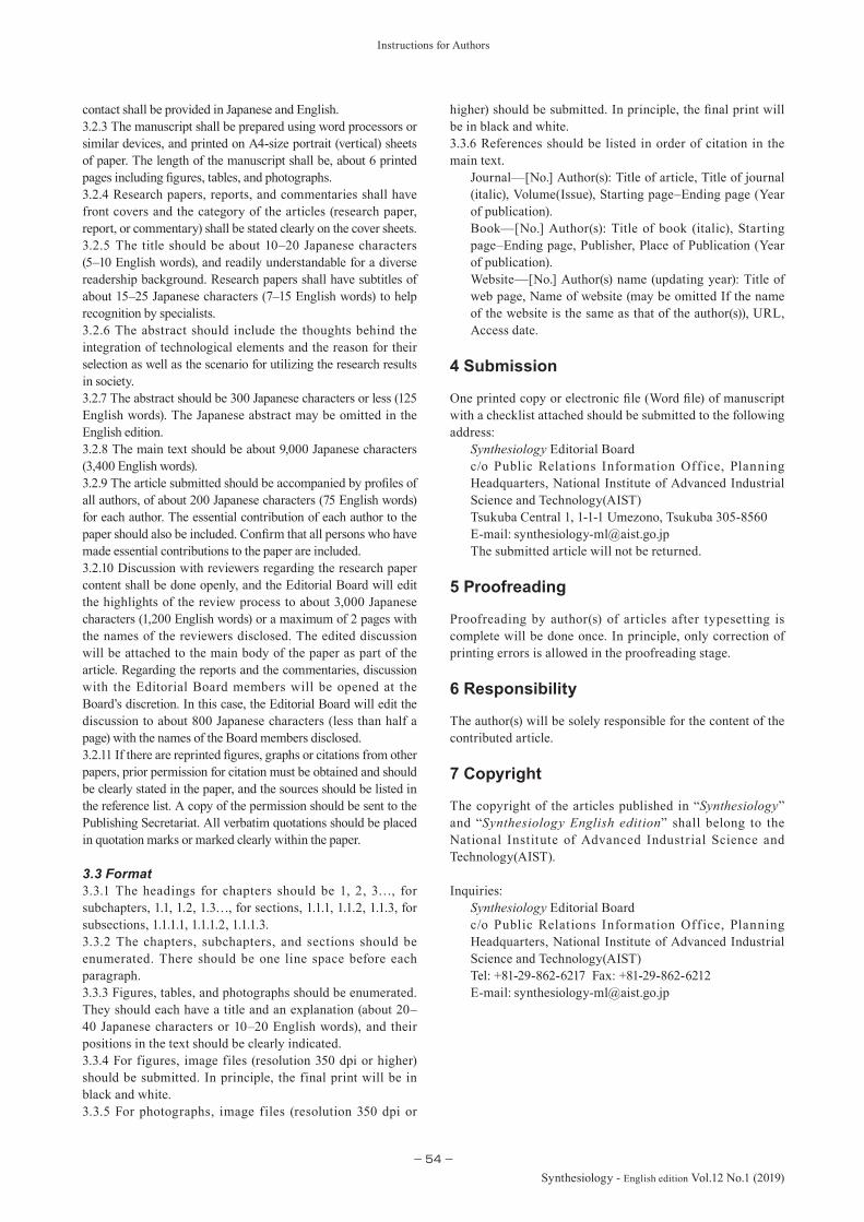
Instructions for Authors
−54−
Synthesiology - English edition Vol.12 No.1 (2019)
contact shall be provided in Japanese and English.3.2.3 The manuscript shall be prepared using word processors or similar devices, and printed on A4-size portrait (vertical) sheets of paper. The length of the manuscript shall be, about 6 printed pages including figures, tables, and photographs.3.2.4 Research papers, reports, and commentaries shall have front covers and the category of the articles (research paper, report, or commentary) shall be stated clearly on the cover sheets.3.2.5 The title should be about 10–20 Japanese characters (5–10 English words), and readily understandable for a diverse readership background. Research papers shall have subtitles of about 15–25 Japanese characters (7–15 English words) to help recognition by specialists. 3.2.6 The abstract should include the thoughts behind the integration of technological elements and the reason for their selection as well as the scenario for utilizing the research results in society.3.2.7 The abstract should be 300 Japanese characters or less (125 English words). The Japanese abstract may be omitted in the English edition.3.2.8 The main text should be about 9,000 Japanese characters (3,400 English words).3.2.9 The article submitted should be accompanied by profiles of all authors, of about 200 Japanese characters (75 English words) for each author. The essential contribution of each author to the paper should also be included. Confirm that all persons who have made essential contributions to the paper are included.3.2.10 Discussion with reviewers regarding the research paper content shall be done openly, and the Editorial Board will edit the highlights of the review process to about 3,000 Japanese characters (1,200 English words) or a maximum of 2 pages with the names of the reviewers disclosed. The edited discussion will be attached to the main body of the paper as part of the article. Regarding the reports and the commentaries, discussion with the Editorial Board members will be opened at the Board’s discretion. In this case, the Editorial Board will edit the discussion to about 800 Japanese characters (less than half a page) with the names of the Board members disclosed.3.2.11 If there are reprinted figures, graphs or citations from other papers, prior permission for citation must be obtained and should be clearly stated in the paper, and the sources should be listed in the reference list. A copy of the permission should be sent to the Publishing Secretariat. All verbatim quotations should be placed in quotation marks or marked clearly within the paper.
3.3 Format3.3.1 The headings for chapters should be 1, 2, 3…, for subchapters, 1.1, 1.2, 1.3…, for sections, 1.1.1, 1.1.2, 1.1.3, for subsections, 1.1.1.1, 1.1.1.2, 1.1.1.3.3.3.2 The chapters, subchapters, and sections should be enumerated. There should be one line space before each paragraph.3.3.3 Figures, tables, and photographs should be enumerated. They should each have a title and an explanation (about 20–40 Japanese characters or 10–20 English words), and their positions in the text should be clearly indicated.3.3.4 For figures, image files (resolution 350 dpi or higher) should be submitted. In principle, the final print will be in black and white.3.3.5 For photographs, image files (resolution 350 dpi or
higher) should be submitted. In principle, the final print will be in black and white.3.3.6 References should be listed in order of citation in the main text.
Journal—[No.] Author(s): Title of article, Title of journal (italic), Volume(Issue), Starting page–Ending page (Year of publication).Book—[No.] Author(s): Title of book (italic), Starting page–Ending page, Publisher, Place of Publication (Year of publication).Website—[No.] Author(s) name (updating year): Title of web page, Name of website (may be omitted If the name of the website is the same as that of the author(s)), URL, Access date.
4 Submission
One printed copy or electronic file (Word file) of manuscript with a checklist attached should be submitted to the following address:
Synthesiology Editorial Boardc/o Public Relations Information Off ice, Planning Headquarters, National Institute of Advanced Industrial Science and Technology(AIST)Tsukuba Central 1, 1-1-1 Umezono, Tsukuba 305-8560E-mail: The submitted article will not be returned.
5 Proofreading
Proofreading by author(s) of articles after typesetting is complete will be done once. In principle, only correction of printing errors is allowed in the proofreading stage. 6 Responsibility
The author(s) will be solely responsible for the content of the contributed article. 7 Copyright
The copyright of the articles published in “Synthesiology” and “Synthesiology English edition” shall belong to the National Institute of Advanced Industrial Science and Technology(AIST). Inquiries:
Synthesiology Editorial Boardc/o Public Relations Information Off ice, Planning Headquarters, National Institute of Advanced Industrial Science and Technology(AIST)Tel: +81-29-862-6217 Fax: +81-29-862-6212E-mail:
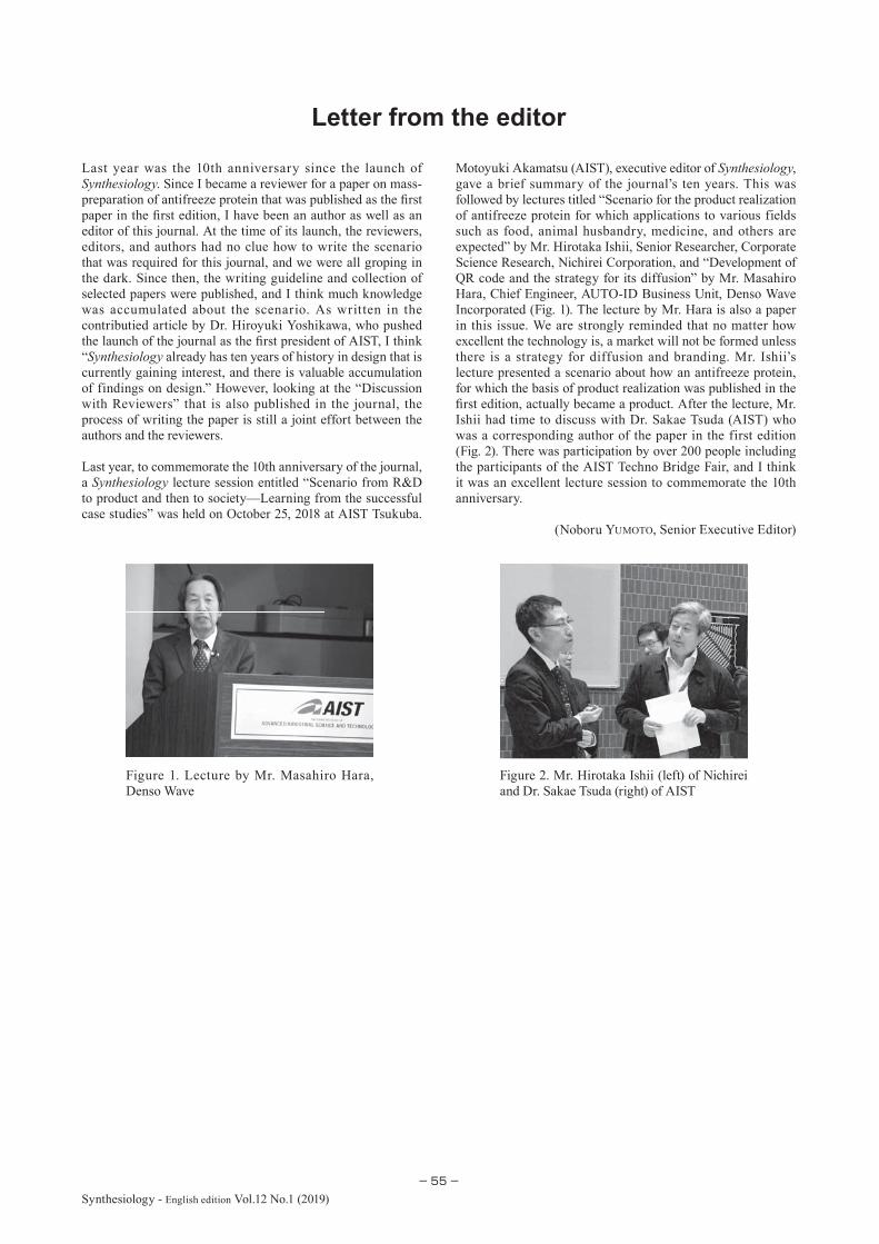
-55-Synthesiology - English edition Vol.12 No.1 (2019)
Letter from the editor
Last year was the 10th anniversary since the launch of Synthesiology. Since I became a reviewer for a paper on mass-preparation of antifreeze protein that was published as the fi rst paper in the fi rst edition, I have been an author as well as an editor of this journal. At the time of its launch, the reviewers, editors, and authors had no clue how to write the scenario that was required for this journal, and we were all groping in the dark. Since then, the writing guideline and collection of selected papers were published, and I think much knowledge was accumulated about the scenario. As written in the contributied article by Dr. Hiroyuki Yoshikawa, who pushed the launch of the journal as the fi rst president of AIST, I think “Synthesiology already has ten years of history in design that is currently gaining interest, and there is valuable accumulation of findings on design.” However, looking at the “Discussion with Reviewers” that is also published in the journal, the process of writing the paper is still a joint effort between the authors and the reviewers.
Last year, to commemorate the 10th anniversary of the journal, a Synthesiology lecture session entitled “Scenario from R&D to product and then to society—Learning from the successful case studies” was held on October 25, 2018 at AIST Tsukuba.
Motoyuki Akamatsu (AIST), executive editor of Synthesiology, gave a brief summary of the journal’s ten years. This was followed by lectures titled “Scenario for the product realization of antifreeze protein for which applications to various fields such as food, animal husbandry, medicine, and others are expected” by Mr. Hirotaka Ishii, Senior Researcher, Corporate Science Research, Nichirei Corporation, and “Development of QR code and the strategy for its diffusion” by Mr. Masahiro Hara, Chief Engineer, AUTO-ID Business Unit, Denso Wave Incorporated (Fig. 1). The lecture by Mr. Hara is also a paper in this issue. We are strongly reminded that no matter how excellent the technology is, a market will not be formed unless there is a strategy for diffusion and branding. Mr. Ishii’s lecture presented a scenario about how an antifreeze protein, for which the basis of product realization was published in the fi rst edition, actually became a product. After the lecture, Mr. Ishii had time to discuss with Dr. Sakae Tsuda (AIST) who was a corresponding author of the paper in the first edition (Fig. 2). There was participation by over 200 people including the participants of the AIST Techno Bridge Fair, and I think it was an excellent lecture session to commemorate the 10th anniversary.
(Noboru YUMOTO, Senior Executive Editor)
Figure 1. Lecture by Mr. Masahiro Hara, Denso Wave
Figure 2. Mr. Hirotaka Ishii (left) of Nichirei and Dr. Sakae Tsuda (right) of AIST

Synthesiology - English edition Vol. 12 No. 1, Aug. 2019Edited by Synthesiology Editorial Board
Published by National Institute of Advanced Industrial Science and Technology (AIST)
Aim of Synthesiology― Utilizing the fruits of research for social prosperity ―
There is a wide gap between scientific achievement and its utilization by society. The history of modern science is replete with results that have taken life-times to reach fruition. This disparity has been called the valley of death, or the nightmare stage. Bridging this difference requires scientists and engineers who understand the potential value to society of their achievements. Despite many previous attempts, a systematic dissemination of the links between scientific achievement and social wealth has not yet been realized.
The unique aim of the journal Synthesiology is its focus on the utilization of knowledge for the creation of social wealth, as distinct from the accumulated facts on which that wealth is engendered. Each published paper identifies and integrates component technologies that create value to society. The methods employed and the steps taken toward implementation are also presented.
Editor in Chief: Y. MIKI
Senior Executive Editor: N. YUMOTO (National Cerebral and Cardiovascular Center), H. OBARA
Executive Editors: T. KANAYAMA, T. SHIMIZU, M. MAKINO, M. AKAMATSU, N. KOBAYASHI (Waseda University)Editors: N. AYA, Y. ARIMOTO (RIKEN), K. IKEGAMI, S. ICHIMURA (Waseda University), Y. OGASAKA (Japan Science and
Technology Agency), A. ONO, M. GOTOH, S. NAITOU, K. FUJI, T. MATSUI (Institute of Information Security), H. YOSHIKAWA (Japan Science and Technology Agency), Y. WATANABE
Publishing Secretariat: Public Relations Information Office, Planning Headquarters, AIST
c/o Public Relations Information Office, Planning Headquarters, AIST Tsukuba Central 1, 1-1-1 Umezono, Tsukuba 305-8560, Japan Tel: +81-29-862-6217 Fax: +81-29-862-6212 s URL: http://www.aist.go.jp/aist_e/research_results/publications/synthesiology_e
● Reproduction in whole or in part without written permission is prohibited.
Synthesiology Editorial Board